

Makita M363 Instruction Manual
1
ENGLISH
INSTRUCTION MANUAL
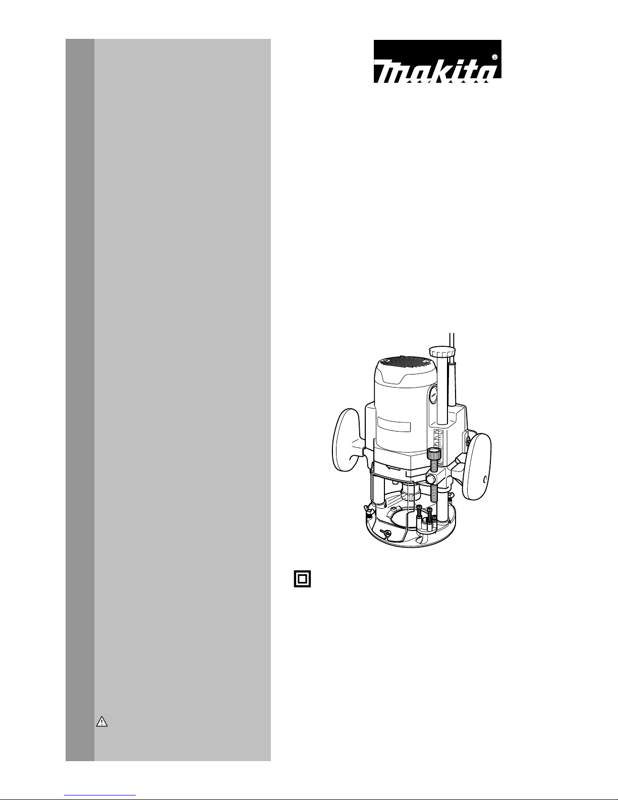
DOUBLE INSULATION
WARNING:
For your personal safety, READ and UNDERSTAND before using.
SAVE THESE INSTRUCTIONS FOR FUTURE REFERENCE.
Router
M363
004924

2
ENGLISH
SPECIFICATIONS
Model M363
Collet chuck capacity 12 mm or 1/2"
Plunge capacity 0 - 60 mm
No load speed (min-1) 22,000
Overall height 300 mm
Net weight 5.5 Kg
Safety class /II
• Due to our continuing programme of research and development, the specifications herein are subject to change without notice.
• Note: Specifications may differ from country to country.
ENA100-1
GENERAL SAFETY RULES
WARNING! Read all instructions. Failure to follow all
instructions listed below may result in electric shock, fire
and/or serious injury. The term "power tool" in all of the
warnings listed below refers to your mains-operated
(corded) power tool or battery-operated (cordless) power
tool.
SAVE THESE INSTRUCTIONS.
Work Area
1. Keep work area clean and well lit. Cluttered and
dark areas invite accidents.
2. Do not operate power tools in explosive
atmospheres, such as in the presence of
flammable liquids, gases or dust. Power tools
create sparks which may ignite the dust or fumes.
3. Keep children and bystanders away while
operating a power tool. Distractions can cause
you to lose control.
Electrical Safety
4. Power tool plugs must match the outlet. Never
modify the plug in any way. Do not use any
adapter plugs with earthed (grounded) power
tools. Unmodified plugs and matching outlets will
reduce risk of electric shock.
5. Avoid bod y contact with earthed or grounded
surfaces such as pipes, radiators, ranges and
refrigerators. There is an increased risk of
electric shock if your body is earthed or grounded.
6. Do not expose power tools to rain or wet
conditions. Water entering a power tool will
increase the risk of electric shock.
7. Do not abuse the cord. Never use the cord for
carrying, pulling or unplugging the power tool.
Keep cord away from heat, oil, sharp edges or
moving parts. Damaged or entangled cords
increase the risk of electric shock.
8. When operating a power tool outdoors, use an
extension cord suitable for outdoor use. Use of
a cord suitable for outdoor use reduces the risk of
electric shock.
Personal Safety
9. Stay alert, watch what you are doing and use
common sense when operating a power tool.
Do not use a power tool while you are tired or
under the influence of drugs, alcohol or
medication. A moment of inattention while
operating power tools may result in serious
personal injury.
10. Use safety equipment. Always wear eye
protection. Safety equipment such as dust mask,
non-skid safety shoes, hard hat, or hearing
protection used for appropriate conditions will
reduce personal injuries.
11. Avoid accidental starting. Ensure the switch is
in the off-position before plugging in. Carrying
power tools with your finger on the switch or
plugging in power tools that have the switch on
invites accidents.
12. Remove any adjusting key or wrench before
turning the power tool on. A wrench or a key left
attached to a rotating part of the power tool may
result in personal injury.
13. Do not overreach. Keep proper footing and
balance at all times. This enables better control
of the power tool in unexpected situations.
14. Dress properly. Do not wear loose clothing or
jewellery. Keep your hair, clothing, and gloves
away from moving parts. Loose clothes,
jewellery or long hair can be caught in moving
parts.
15. If devices are provided for the connection of
dust extraction and collection facilities,
ensure these are connected and properly used.
Use of these devices can reduce dust-related
hazards.
Power tool use and care
16. Do not force the power tool. Use the correct
power tool for your application. The correct
power tool will do the job better and safer at the
3
rate for which it was designed.
17. Do not use the power tool if the switch does
not turn it on and off. Any power too l that cannot
be controlled with the switch is dangerous and
must be repaired.
18. Disconnect the plug from the power source
and/or the battery pack from the power tool
before making any adjustments, changing
accessories, or storing power tools. Such
preventive safety measures reduce the risk of
starting the power tool accidentally.
19. Store idle power tools out of the reach of
children and do not allow persons unfamiliar
with the power tool or these instructions to
operate the power tool. Power tools are
dangerous in the hands of untrained users.
20. Maintain power tools. Check for misalignment
or binding of moving parts, breakage of parts
and any other condition that may affect the
power tools operation. If damaged, have the
power tool repaired before use. Many accidents
are caused by poorly maintained power tools.
21. Keep cutting tools sharp and clean. Properly
maintained cutting tools with sharp cutting edges
are less likely to bind and are easier to control.
22. Use the power tool, accessories and tool bits
etc. in accordance with these instructions and
in the manner intended for the particular type
of power tool, taking into account the working
conditions and the work to be performed. Use
of the power tool for operations different from
those intended could result in a hazardous
situation taking into account the working
conditions and the work to be performed.Use of
the power tool for operations different from those
intended could result in a hazardous situation.
SERVICE
23. Have your power tool serviced by a qualified
repair person using only identical replacement
parts. This will ensure that the safety of the power
tool is maintained.
ENB033-3
ADDITIONAL SAFETY RULES
1. Hold tool by insulated gripping surfaces when
performing an operation where the cutting tool
may contact hidden wiring or its own cord.
Contact with a "live" wire will make exposed metal
parts of the tool "live" and shock the operator.
2. Wear hearing protection during extended
period of operation.
3. Handle the bits very carefully.
4. Check the bit carefully for cracks or damage
before operation. Replace cracked or
damaged bit immediately.
5. Avoid cutting nails. Inspect for and remove all
nails from the workpiece before operation.
6. Hold the tool firmly with both hands.
7. Keep hands away from rotating parts.
8. Make sure the bit is not contacting the
workpiece before the switch is turned on.
9. Before using the tool on an actual workpiece,
let it run for a while. Watch for vibration or
wobbling that could indicate improperly
installed bit.
10. Be careful of the bit rotating direction and the
feed direction.
11. Do not leave the tool running. Operate the tool
only when hand-held.
12. Always switch off and wait for the bit to come
to a complete stop before removing the tool
from workpiece.
13. Do not touch the bit immediately after
operation; it may be extremely hot and could
burn your skin.
14. Always lead the power supply cord away from
the tool towards the rear.
15. Do not smear the tool base carelessly with
thinner, gasoline, oil or the like. They may
cause cracks in the tool base.
16. Draw attention to the need to use cutters of the
correct shank diameter and which are suitable
for the speed of the tool.
17. Always use the correct dust mask/respirator
for the material and application you are
working with.
SAVE THESE INSTRUCTIONS.
FUNCTIONAL DESCRIPTION
CAUTION:
• Always be sure that the tool is switched off and
unplugged before adjusting or checking function on
the tool.
Adjusting the depth of cut
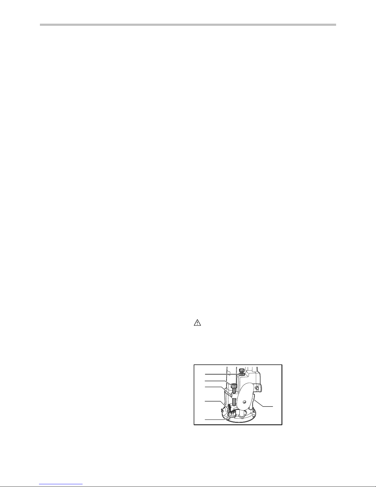
1
2
3
4
5
6
004925
1. Nylon nut
2. Stopper pole
3. Fast-feed button
4. Adjusting hex
bolt
5. Stopper
6. Lock lever
4
Place the tool on a flat surface. Loosen the lock lever
and lower the tool body until the bit just touches the flat
surface. Press the lock lever down to lock the tool body.
While pressing the fast-feed button, move the stopper
pole up or down until the desired depth of cut is obtained.
Minute depth adjustments can be obtained by turning
the stopper pole (1.5 mm per turn).
CAUTION:
• The depth of cut should not be more than 20 mm at
a pass when cutting grooves. For extra-deep
grooving operations, make two or three passes
with progressively deeper bit settings.
Nylon nut
For tool without the knob
The upper limit of the tool body can be adjusted by
turning the nylon nut. Do not lower the nylon nut too low.
The bit will protrude dangerously.
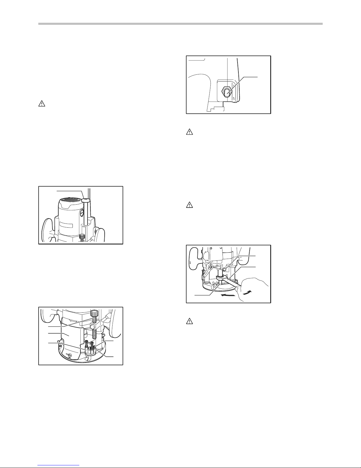
For tool with the knob
1
005111
By turning the knob, the upper limit of the tool body can
be adjusted. When the tip of the bit is retracted more
than required in relation to the base plate surface, turn
the knob to lower the upper limit. Do not lower the knob
too low. The bit will protrude dangerously.
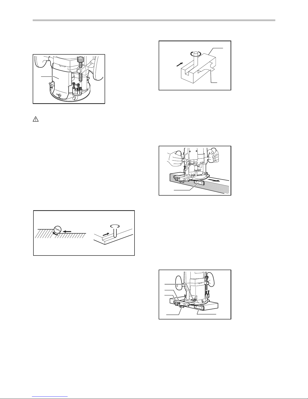
Stopper block
1
2
3
4
5
004926
As the rotary stopper has three adjusting hex bolts, you
can easily obtain three different depths of cut without
readjusting the stopper pole. To adjust the hex bolts,
loosen the hex nuts on them and turn the hex bolts. After
obtaining the desired position, tighten the hex nuts to
secure the hex bolts.
Switch action
1
004927
CAUTION:
• Before plugging in the tool, always check to see
that the tool is switched off.
• Make sure that the shaft lock is released before the
switch is turned on.
To sta r t the t oo l , m o ve t he s witch le v er t o t he I pos i tion.
To s t op the tool, mo ve th e s w itch lever t o the O position.
ASSEMBLY
CAUTION:
• Always be sure that the tool is switched off and
unplugged before carrying out any work on the
tool.
Installing or removing the bit
1
2
3
004928
CAUTION:
• Install the bit securely. Always use only the wrench
provided with the tool. A loose or overtightened bit
can be dangerous.
• Do not tighten the collet nut without inserting a bit
or install small shank bits without using a collet
sleeve. Either can lead to breakage of the collet
cone.
Insert the bit all the way into the collet cone. Press the
shaft lock to keep the shaft stationary and use the
wrench to tighten the collet nut securely. When using
router bits with smaller shank diameter, first insert the
appropriate collet sleeve into the collet cone, then install
the bit as described above.
To remove the bit, follow the installation procedure in
reverse.
1. Shaft lock
2. Wrench
3. Bit
1. Switch lever
1. Stopper pole
2. Chip deflector
3. Stopper
4. Adjusting hex
bolt
5. Hex nut
1. Knob
5
OPERATION
1
005112
CAUTION:
• Before operation, always make sure that the tool
body automatically rises to the upper limit and the
bit does not protrude from the tool base when the
lock lever is loosened.
• Before operation, always make sure that the chip
deflector is installed properly.
Set the tool base on the workpiece to be cut without the
bit making any contact. Then turn the tool on and wait
until the bit attains full speed. Lower the tool body and
move the tool forward over the workpiece surface,
keeping the tool base flush and advancing smoothly until
the cutting is complete.
When doing edge cutting, the workpiece surface should
be on the left side of the bit in the feed direction.
1
2
3
4
4
2
001984
NOTE:
• Moving the tool forward too fast may cause a poor
quality of cut, or damage to the bit or motor.
Moving the tool forward too slowly may burn and
mar the cut. The proper feed rate will depend on
the bit size, the kind of workpiece and depth of cut.
Before beginning the cut on the actual workpiece, it
is advisable to make a sample cut on a piece of
scrap lumber. This will show exactly how the cut
will look as well as enable you to check
dimensions.
1
2
3
4
001985
NOTE:
• When using the straight guide or the trimmer guide,
be sure to install it on the right side in the feed
direction. This will help to keep it flush with the side
of the workpiece.
Straight guide
1
004929
The straight guide is effectively used for straight cuts
when chamfering or grooving.
Install the straight guide on the guide holder with the
thumb screw (B). Insert the guide holder into the holes in
the tool base and tighten the thumb screw (A). To adjust
the distance between the bit and the straight guide,
loosen the thumb screw (B) and turn the fine adjusting
screw (1.5 mm per turn). At the desired distance, tighten
the thumb screw (B) to secure the straight guide in
place.
1
2
3
4
5
004930
Wider straight guide of desired dimensions may be
made by using the convenient holes in the guide to bolt
on extra pieces of wood.
1. Workpiece
2. Bit revolving direction
3. View from the top of the tool
4. Feed direction
1. Wing bolt (A)
2. Guide holder
3. Fine adjusting
screw
4. Wing bolt (B)
5. Straight guide
1. Straight guide
1. Feed direction
2. Bit revolving
direction
3. Workpiece
4. Straight guide
1. Chip deflector
 Loading...