

Page 1
EN
Router INSTRUCTION MANUAL 6
FR
DE
IT
NL
ES
PT
DA
EL
TR
Défonceuse MANUEL D’INSTRUCTIONS 11
Oberfräse BETRIEBSANLEITUNG 17
Fresatrice verticale ISTRUZIONI PER L’USO 23
Bovenfrees GEBRUIKSAANWIJZING 29
Rebajadora
Tupia MANUAL DE INSTRUÇÕES 41
Overfræser BRUGSANVISNING 47
Ρούτερ ΕΓΧΕΙΡΙΔΙΟ ΟΔΗΓΙΩΝ 52
Freze KULLANMA KILAVUZU 58
M3601
MANUAL DE
INSTRUCCIONES
35
Page 2
1
Fig.1
Fig.2
Fig.3
2
1
Fig.5
2
1
1
2
Fig.6
1
2
3
4
5
Fig.7
Fig.4
1
1
4
2
3
2
2
3
4
4
5
Fig.8
2
Page 3
1
23
12
Fig.9
Fig.10
Fig.11
4
1
3
Fig.13
Fig.14
2
Fig.15
A
Fig.12
R
Fig.16
3
Page 4

Fig.17
Fig.21
Fig.18
Fig.19
Fig.20
Fig.22
Fig.23
Fig.24
4
Page 5
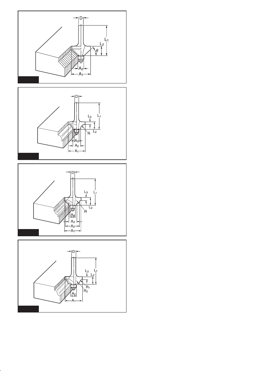
Fig.25
Fig.26
Fig.27
Fig.28
5
Page 6

ENGLISH (Original instructions)
SPECIFICATIONS
Model: M3601
Collet chuck capacity 6 mm, 1/4″ and/or 8 mm
Plunge capacity 0 - 35 mm
No load speed 27,000 min
Overall height 218 mm
Net weight 2.7 kg
Safety class
• Due to our continuing program of research and development, the specications herein are subject to change
without notice.
• Specications may differ from country to country.
• Weight according to EPTA-Procedure 01/2003
Intended use
The tool is intended for ush trimming and proling of
wood, plastic and similar materials.
Power supply
The tool should be connected only to a power supply of
the same voltage as indicated on the nameplate, and
can only be operated on single-phase AC supply. They
are double-insulated and can, therefore, also be used
from sockets without earth wire.
Noise
The typical A-weighted noise level determined according to EN60745:
Sound pressure level (LpA) : 91 dB(A)
Sound power level (LWA) : 102 dB (A)
Uncertainty (K) : 3 dB(A)
WARNING: Wear ear protection.
Vibration
The vibration total value (tri-axial vector sum) determined according to EN60745:
Work mode: cutting grooves in MDF
Vibration emission (a
Uncertainty (K) : 1.5 m/s
NOTE: The declared vibration emission value has
been measured in accordance with the standard test
method and may be used for comparing one tool with
another.
NOTE: The declared vibration emission value
may also be used in a preliminary assessment of
exposure.
) : 7.5 m/s
h
2
2
WARNING: The vibration emission during actual
use of the power tool can differ from the declared
emission value depending on the ways in which the
tool is used.
WARNING: Be sure to identify safety measures
to protect the operator that are based on an estimation of exposure in the actual conditions of use (taking
account of all parts of the operating cycle such as
the times when the tool is switched off and when it is
running idle in addition to the trigger time).
EC Declaration of Conformity
For European countries only
Makita declares that the following Machine(s):
Designation of Machine: Router
Model No./ Type: M3601
Conforms to the following European Directives:
2006/42/EC
They are manufactured in accordance with the following
standard or standardized documents: EN60745
The technical le in accordance with 2006/42/EC is
available from:
Makita, Jan-Baptist Vinkstraat 2, 3070, Belgium
31.8.2015
Yasushi Fukaya
Director
Makita, Jan-Baptist Vinkstraat 2, 3070, Belgium
General power tool safety warnings
WARNING: Read all safety warnings and
all instructions. Failure to follow the warnings and
instructions may result in electric shock, re and/or
serious injury.
-1
/II
6 ENGLISH
Page 7

Save all warnings and instructions for future reference.
The term "power tool" in the warnings refers to your
mains-operated (corded) power tool or battery-operated
(cordless) power tool.
Router safety warnings
1. Hold power tool by insulated gripping surfaces, because the cutter may contact its own
cord. Cutting a “live” wire may make exposed
metal parts of the power tool “live” and shock the
operator.
2. Use clamps or another practical way to secure
and support the workpiece to a stable platform. Holding the work by your hand or against
the body leaves it unstable and may lead to loss of
control.
3. Wear hearing protection during extended
period of operation.
4. Handle the router bits very carefully.
5. Check the router bit carefully for cracks or
damage before operation. Replace cracked or
damaged bit immediately.
6. Avoid cutting nails. Inspect for and remove all
nails from the workpiece before operation.
7. Hold the tool rmly with both hands.
8. Keep hands away from rotating parts.
9. Make sure the router bit is not contacting the
workpiece before the switch is turned on.
10. Before using the tool on an actual workpiece,
let it run for a while. Watch for vibration or
wobbling that could indicate improperly
installed bit.
11. Be careful of the router bit rotating direction
and the feed direction.
12. Do not leave the tool running. Operate the tool
only when hand-held.
13. Always switch off and wait for the router bit to
come to a complete stop before removing the
tool from workpiece.
14. Do not touch the router bit immediately after
operation; it may be extremely hot and could
burn your skin.
15. Do not smear the tool base carelessly with
thinner, gasoline, oil or the like. They may
cause cracks in the tool base.
16. Use router bits of the correct shank diameter
suitable for the speed of the tool.
17. Some material contains chemicals which may
be toxic. Take caution to prevent dust inhalation and skin contact. Follow material supplier
safety data.
18. Always use the correct dust mask/respirator
for the material and application you are working with.
SAVE THESE INSTRUCTIONS.
WARNING: DO NOT let comfort or familiarity
with product (gained from repeated use) replace
strict adherence to safety rules for the subject
product. MISUSE or failure to follow the safety
rules stated in this instruction manual may cause
serious personal injury.
FUNCTIONAL
DESCRIPTION
CAUTION: Always be sure that the tool is
switched off and unplugged before adjusting or
checking function on the tool.
Adjusting the depth of cut
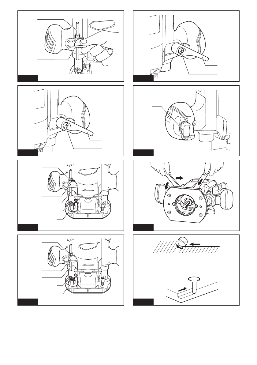
1. Place the tool on a at surface. Loosen the screw
securing the stopper pole.
► Fig.1: 1. Stopper pole 2. Screw
2. Loosen the lock lever and lower the tool body until
the router bit just touches the at surface. Tighten the
lock lever to lock the tool body.
► Fig.2: 1. Lock lever 2. Screw
3. Lower the stopper pole until it makes contact with
the adjusting hex bolt. Align the depth pointer with the
"0" graduation.
► Fig.3: 1. Depth pointer 2. Screw 3. Stopper pole
4. Adjusting hex bolt 5. Stopper block
4. Raise the stopper pole until the desired depth
of cut is obtained. The depth of cut is indicated on the
scale (1 mm per graduation) by the depth pointer. Then
tighten the screw to secure the stopper pole.
5. Your predetermined depth of cut can be obtained
by loosening the lock lever and then lowering the tool
body until the stopper pole makes contact with the
adjusting hex bolt.
CAUTION: Since excessive cutting may cause
overload of the motor or difculty in controlling
the tool, the depth of cut should not be more than
15 mm (9/16″) at a pass when cutting grooves
with an 8 mm (5/16″) diameter bit.
CAUTION: When cutting grooves with a 20
mm (13/16″) diameter bit, the depth of cut should
not be more than 5 mm (3/16″) at a pass.
CAUTION: When you wish to cut grooves
more than 15 mm (9/16″) deep with an 8 mm
(5/16″) diameter bit or more than 5 mm (3/16″)
deep with a 20 mm (13/16″) diameter bit, make
several passes with progressively deeper bit
settings.
7 ENGLISH
Page 8

Stopper block
The stopper block has three adjusting hex bolts which
raise or lower 0.8 mm (approx. 1/32″) per turn. You can
easily obtain three different depths of cut using these
adjusting hex bolts without readjusting the stopper pole.
► Fig.4: 1. Depth pointer 2. Screw 3. Stopper pole
4. Adjusting hex bolt 5. Stopper block
1. Adjust the lowest hex bolt to obtain the deepest
depth of cut, following the method of "Adjusting the
depth of cut".
2. Adjust the two remaining hex bolts to obtain shal-
lower depths of cut. The differences in height of these
hex bolts are equal to the differences in depths of cut.
3. Turn the hex bolts to adjust the depth. The stopper
block is also convenient for making three passes with
progressively deeper bit settings when cutting deep
grooves.
NOTE: When using a bit having total length of 60 mm
(2-3/8″) or more, or edge length of 35 mm (1-3/8″) or
more, the depth of cut cannot be adjusted as previously mentioned. To adjust, proceed as follows:
1. Loosen the lock lever and carefully adjust bit
protrusion below the tool base to the desired
depth of cut by moving the tool body up or
down.
2. Retighten the lock lever to lock the tool body at
that depth of cut. Keep the tool body locked at
this position during use.
Since the bit always protrudes from the tool base, be
careful when handling the tool.
Adjusting the lock lever
The locked position of the lock lever is adjustable. To
adjust it, remove the screw securing the lock lever. The
lock lever will come off. Set the lock lever at the desired
angle. After adjustment, tighten the lock lever clockwise.
► Fig.5: 1. Lock lever 2. Screw
Switch action
CAUTION: Before plugging in the tool, always
check to see that the switch trigger actuates
properly and returns to the "OFF" position when
released.
To start the tool, simply pull the switch trigger. Release
the switch trigger to stop.
► Fig.6: 1. Switch trigger
Installing or removing the router bit
Insert the bit all the way into the collet cone and tighten
the collet nut securely with the two wrenches. An 8 mm
collet cone may be also provided as a standard equipment (depending on the country) besides the 6 mm or
1/4″ collet cone that is factory installed on the tool. Use
the correct size collet cone for the bit which you intend
to use.
► Fig.7
To remove the bit, follow the installation procedure in
reverse.
CAUTION: Install the router bit securely.
Always use only the wrench provided with the
tool. A loose or overtightened router bit can be
dangerous.
CAUTION: Do not tighten the collet nut with-
out inserting a bit. It can lead to breakage of the
collet cone.
OPERATION
Set the tool base on the workpiece to be cut without
the router bit making any contact. Then turn the tool on
and wait until the router bit attains full speed. Lower the
tool body and move the tool forward over the workpiece
surface, keeping the tool base ush and advancing
smoothly until the cutting is complete.
When doing edge cutting, the workpiece surface should
be on the left side of the router bit in the feed direction.
► Fig.8: 1. Workpiece 2. Bit revolving direction
3. View from the top of the tool 4. Feed
direction
NOTE: Moving the tool forward too fast may cause
a poor quality of cut, or damage to the router bit or
motor. Moving the tool forward too slowly may burn
and mar the cut. The proper feed rate will depend on
the router bit size, the kind of workpiece and depth
of cut.
Before beginning the cut on the actual workpiece, it
is advisable to make a sample cut on a piece of scrap
lumber. This will show exactly how the cut will look as
well as enable you to check dimensions.
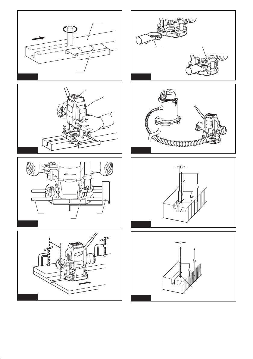
NOTE: When using the straight guide or the trimmer
guide, be sure to install it on the right side in the feed
direction. This will help to keep it ush with the side of
the workpiece.
► Fig.9: 1. Feed direction 2. Bit revolving direction
3. Workpiece 4. Straight guide
ASSEMBLY
CAUTION: Always be sure that the tool is
switched off and unplugged before carrying out
any work on the tool.
8 ENGLISH
Page 9

Straight guide
The straight guide is effectively used for straight cuts
when chamfering or grooving.
► Fig.10
To install the straight guide, insert the guide bars into
the holes in the tool base. Adjust the distance between
the bit and the straight guide. At the desired distance,
tighten the wing bolts to secure the straight guide in
place. When cutting, move the tool with the straight
guide ush with the side of the workpiece.
► Fig.11: 1. Guide bar 2. Clamp screw 3. Straight
guide
If the distance (A) between the side of the workpiece
and the cutting position is too wide for the straight
guide, or if the side of the workpiece is not straight, the
straight guide cannot be used. In this case, rmly clamp
a straight board to the workpiece and use it as a guide
against the trimmer base. Feed the tool in the direction
of the arrow.
► Fig.12
Dust nozzle set (For European
countries only)
Use the dust nozzle for dust extraction. Install the dust
nozzle on the tool base using the thumb screw so that
protrusion on the dust nozzle t to the notch in the
tool base. Then connect a vacuum cleaner to the dust
nozzle.
► Fig.13: 1. Dust nozzle 2. Thumb screw
► Fig.14
MAINTENANCE
CAUTION: Always be sure that the tool is
switched off and unplugged before attempting to
perform inspection or maintenance.
NOTICE: Never use gasoline, benzine, thinner,
alcohol or the like. Discoloration, deformation or
cracks may result.
To maintain product SAFETY and RELIABILITY,
repairs, any other maintenance or adjustment should
be performed by Makita Authorized or Factory Service
Centers, always using Makita replacement parts.
OPTIONAL
ACCESSORIES
If you need any assistance for more details regarding these accessories, ask your local Makita Service
Center.
• Straight & groove forming bits
• Edge forming bits
• Laminate trimming bits
NOTE: Some items in the list may be included in the
tool package as standard accessories. They may
differ from country to country.
Router bits
Straight bit
► Fig.15
Unit:mm
D A L1 L2
6 20 50 15
1/4″
8 8 60 25
6 8 50 18
1/4″
6 6 50 18
1/4″
“U”Grooving bit
► Fig.16
Unit:mm
D A L1 L2 R
6 6 50 18 3
“V”Grooving bit
► Fig.17
Unit:mm
D A L1 L2 θ
1/4″ 20 50 15 90°
Drill point ush trimming bit
► Fig.18
Unit:mm
D A L1 L2 L3
8 8 60 20 35
6 6 60 18 28
CAUTION: These accessories or attachments
are recommended for use with your Makita tool
specied in this manual. The use of any other
accessories or attachments might present a risk of
injury to persons. Only use accessory or attachment
for its stated purpose.
9 ENGLISH
Page 10

Drill point double ush trimming bit
► Fig.19
Unit:mm
D A L1 L2 L3 L4
8 8 80 55 20 25
6 6 70 40 12 14
Corner rounding bit
► Fig.20
Unit:mm
D A1 A2 L1 L2 L3 R
6 25 9 48 13 5 8
6 20 8 45 10 4 4
Chamfering bit
► Fig.21
Unit:mm
D A L1 L2 L3 θ
6 23 46 11 6 30°
6 20 50 13 5 45°
6 20 49 14 2 60°
Ball bearing chamfering bit
► Fig.25
Unit:mm
D A1 A2 L1 L2 θ
6 26 8 42 12 45°
1/4″
6 20 8 41 11 60°
Ball bearing beading bit
► Fig.26
Unit:mm
D A1 A2 A3 L1 L2 L3 R
6 20 12 8 40 10 5.5 4
6 26 12 8 42 12 4.5 7
Ball bearing cove beading bit
► Fig.27
Unit:mm
D A1 A2 A3 A4 L1 L2 L3 R
6 20 18 12 8 40 10 5.5 3
6 26 22 12 8 42 12 5 5
Cove beading bit
► Fig.22
D A L1 L2 R
6 20 43 8 4
6 25 48 13 8
Ball bearing ush trimming bit
► Fig.23
D A L1 L2
6 10 50 20
1/4″
Ball bearing corner rounding bit
► Fig.24
D A1 A2 L1 L2 L3 R
6 15 8 37 7 3.5 3
6 21 8 40 10 3.5 6
1/4″ 21 8 40 10 3.5 6
Unit:mm
Unit:mm
Unit:mm
Ball bearing roman ogee bit
► Fig.28
Unit:mm
D A1 A2 L1 L2 L3 R1 R2
6 20 8 40 10 4.5 2.5 4.5
6 26 8 42 12 4.5 3 6
10 ENGLISH
Page 11

FRANÇAIS (Instructions originales)
SPÉCIFICATIONS
Modèle : M3601
Capacité du mandrin à bague 6 mm, 1/4″ et/ou 8 mm
Capacité de plongée 0 à 35 mm
Vitesse à vide 27 000 min
Hauteur hors tout 218 mm
Poids net 2,7 kg
Catégorie de sécurité
• Étant donné l’évolution constante de notre programme de recherche et de développement, les spécications
contenues dans ce manuel sont sujettes à modication sans préavis.
• Les spécications peuvent varier suivant les pays.
• Poids selon la procédure EPTA 01/2003
Utilisations
L’outil est conçu pour l’afeurage au ras et le prolage
du bois, du plastique et de matériaux semblables.
Alimentation
L’outil ne devra être raccordé qu’à une alimentation
de la même tension que celle qui gure sur la plaque
signalétique, et il ne pourra fonctionner que sur un
courant secteur monophasé. Réalisé avec une double
isolation, il peut de ce fait être alimenté par une prise
sans mise à la terre.
Bruit
Niveau de bruit pondéré A typique, déterminé selon
EN60745 :
Niveau de pression sonore (LpA) : 91 dB (A)
Niveau de puissance sonore (L
Incertitude (K) : 3 dB (A)
) : 102 dB (A)
WA
AVERTISSEMENT : Portez un serre-tête
antibruit.
Vibrations
Valeur totale de vibrations (somme de vecteur triaxial)
déterminée selon EN60745 :
Mode de travail : coupe de rainures sur un panneau de
bres à densité moyenne
Émission de vibrations (ah) : 7,5 m/s
Incertitude (K) : 1,5 m/s
NOTE : La valeur d’émission de vibrations déclarée
a été mesurée conformément à la méthode de test
standard et peut être utilisée pour comparer les outils
entre eux.
NOTE : La valeur d’émission de vibrations déclarée
peut aussi être utilisée pour l’évaluation préliminaire
de l’exposition.
2
2
AVERTISSEMENT : L’émission de vibrations
lors de l’usage réel de l’outil électrique peut être
différente de la valeur d’émission déclarée, suivant la
façon dont l’outil est utilisé.
AVERTISSEMENT : Les mesures de sécurité à
prendre pour protéger l’utilisateur doivent être basées
sur une estimation de l’exposition dans des conditions réelles d’utilisation (en tenant compte de toutes
les composantes du cycle d’utilisation, comme par
exemple le moment de sa mise hors tension, lorsqu’il
tourne à vide et le moment de son déclenchement).
Déclaration de conformité CE
Pour les pays européens uniquement
Makita déclare que la ou les machines suivantes :
Désignation de la machine : Défonceuse
N° de modèle/Type : M3601
sont conformes aux Directives européennes suivantes :
2006/42/CE
et sont fabriquées conformément aux normes ou aux
documents normalisés suivants : EN60745
La documentation technique conforme à la norme
2006/42/CE est disponible auprès de :
Makita, Jan-Baptist Vinkstraat 2, 3070, Belgique
31.8.2015
Yasushi Fukaya
Directeur
Makita, Jan-Baptist Vinkstraat 2, 3070, Belgique
Consignes de sécurité générales
pour outils électriques
AVERTISSEMENT : Lisez toutes les
consignes de sécurité et toutes les instructions. Il
y a risque d’électrocution, d’incendie et/ou de graves
blessures si les mises en garde et les instructions ne
sont pas respectées.
-1
/II
11 FRANÇAIS
Page 12

Conservez toutes les mises en
garde et instructions pour référence ultérieure.
Le terme « outil électrique » dans les avertissements
fait référence à l’outil électrique alimenté par le secteur
(avec cordon d’alimentation) ou à l’outil électrique fonctionnant sur batterie (sans cordon d’alimentation).
Consignes de sécurité pour
défonceuse
1. Tenez l’outil électrique par une surface de
prise isolée, étant donné que l’outil de coupe
peut entrer en contact avec son cordon.
Couper un câble sous tension risque de mettre à
découvert les pièces métalliques de l’outil électrique sous tension et d’électrocuter l’utilisateur.
2. Utilisez des dispositifs de serrage ou un autre
moyen pratique pour xer et soutenir la pièce
sur une plateforme stable. La pièce sera instable et vous risquez d’en perdre la maîtrise si
vous la tenez dans vos mains ou l’appuyez contre
le corps.
3. Portez des protège-tympans si vous utilisez
l’outil pendant une période prolongée.
4. Manipulez les fraises de défonceuse avec
beaucoup de précaution.
5. Vériez soigneusement l’absence de ssures
ou de dommages sur les fraises de défonceuse avant l’utilisation. Remplacez immédia-
tement les fraises ssurées ou abîmées.
6. Prenez garde aux clous pendant la coupe.
Avant de travailler votre pièce, inspectez-la et
retirez-en tous les clous.
7. Tenez l’outil fermement à deux mains.
8. Gardez vos mains à l’écart des pièces en
rotation.
9. Assurez-vous que la fraise de défonceuse
n’est pas en contact avec la pièce avant de
mettre l’outil en marche.
10. Avant d’utiliser l’outil sur une pièce, faites-le
tourner un instant à vide. Soyez attentif aux
vibrations ou sautillements pouvant indiquer
que la fraise n’est pas bien installée ou est mal
équilibrée.
11. Faites attention au sens de rotation de la fraise
de défonceuse et au sens d’avance.
12. N’abandonnez pas l’outil alors qu’il tourne. Ne
faites fonctionner l’outil qu’une fois que vous
l’avez bien en main.
13. Avant de retirer l’outil de la pièce, mettez
toujours l’outil hors tension et attendez que
la fraise de défonceuse soit complètement
immobilisée.
14. Ne touchez pas la fraise de défonceuse immédiatement après avoir terminé le travail ; elle
peut être très chaude et vous brûler la peau.
15. Prenez garde de ne pas tacher le socle de
l’outil avec du diluant, de l’essence, de l’huile
ou toute substance similaire. Elles peuvent
entraîner des ssures sur le socle de l’outil.
16. Utilisez des fraises de défonceuse dont le diamètre de la tige convient à la vitesse de l’outil.
17. Certains matériaux contiennent des produits
chimiques qui peuvent être toxiques. Prenez
les précautions nécessaires pour ne pas
inhaler les poussières et pour éviter tout
contact avec la peau. Suivez les données de
sécurité du fournisseur du matériau.
18. Portez toujours un masque anti-poussières/un
masque ltrant adapté au matériau travaillé et
à l’application utilisée.
CONSERVEZ CES
INSTRUCTIONS.
AVERTISSEMENT : NE vous laissez PAS
tromper (au l d’une utilisation répétée) par un
sentiment d’aisance et de familiarité avec le
produit, en négligeant le respect rigoureux des
consignes de sécurité qui accompagnent le produit en question. La MAUVAISE UTILISATION de
l’outil ou l’ignorance des consignes de sécurité
indiquées dans ce mode d’emploi peut entraîner
de graves blessures.
DESCRIPTION DU
FONCTIONNEMENT
ATTENTION : Assurez-vous toujours que
l’outil est hors tension et débranché avant de
l’ajuster ou de vérier son fonctionnement.
Réglage de la profondeur de la
coupe
1. Placez l’outil sur une surface plane. Desserrez la
vis qui retient la tige d’arrêt.
► Fig.1: 1. Tige d’arrêt 2. Vis
2. Desserrez le levier de verrouillage et abaissez le
corps de l’outil jusqu’à ce que la fraise de défonceuse
entre légèrement en contact avec la surface plane.
Serrez le levier de verrouillage pour verrouiller le corps
de l’outil.
► Fig.2: 1. Levier de verrouillage 2. Vis
3. Abaissez la tige d’arrêt jusqu’à ce qu’elle entre en
contact avec le boulon hexagonal de réglage. Alignez
l’index de profondeur sur la graduation « 0 ».
► Fig.3: 1. Index de profondeur 2. Vis 3. Tige d’arrêt
4. Boulon hexagonal de réglage 5. Bloc
butoir
4. Soulevez la tige d’arrêt jusqu’à ce que vous obte-
niez la profondeur de coupe souhaitée. La profondeur
de coupe est indiquée sur l’échelle (1 mm par graduation) par l’index de profondeur. Puis serrez la vis pour
xer la tige d’arrêt.
5. La profondeur de coupe que vous avez prédé-
terminée peut être obtenue en desserrant le levier de
verrouillage, puis en abaissant le corps de l’outil jusqu’à
ce que la tige d’arrêt entre en contact avec le boulon
hexagonal de réglage.
12 FRANÇAIS
Page 13

ATTENTION : Comme une coupe trop pro-
fonde risquerait de surcharger le moteur et de
rendre difcile la maîtrise de l’outil, la profondeur
de coupe ne doit pas être supérieure à 15 mm
(9/16″) par passe lors du rainurage avec une
fraise de 8 mm (5/16″) de diamètre.
ATTENTION : Lors du rainurage avec une
fraise de 20 mm (13/16″) de diamètre, la profondeur de coupe ne doit pas être supérieure à 5 mm
(3/16″) par passe.
ATTENTION : Si vous souhaitez effectuer un
rainurage de plus de 15 mm (9/16″) de profondeur
avec une fraise de 8 mm (5/16″) de diamètre ou
de plus de 5 mm (3/16″) de profondeur avec une
fraise de 20 mm (13/16″) de diamètre, effectuez
plusieurs passes en augmentant progressivement
la profondeur de la fraise.
Bloc butoir
Le bloc butoir est pourvu de trois boulons hexagonaux
de réglage se soulevant ou s’abaissant de 0,8 mm
(environ 1/32″) par tour. Vous pouvez facilement obtenir
trois profondeurs de coupe différentes à l’aide de ces
boulons hexagonaux de réglage sans avoir à régler à
nouveau la tige d’arrêt.
► Fig.4: 1. Index de profondeur 2. Vis 3. Tige d’arrêt
4. Boulon hexagonal de réglage 5. Bloc
butoir
1. Réglez le boulon hexagonal le plus bas pour obtenir la profondeur de coupe la plus profonde en suivant
la méthode indiquée dans « Réglage de la profondeur
de la coupe ».
2. Réglez les deux boulons hexagonaux restants
pour obtenir des profondeurs de coupe moins profondes. Les différences de hauteur entre ces boulons
hexagonaux sont égales aux différences entre les
profondeurs de coupe.
3. Tournez les boulons hexagonaux pour régler la
profondeur. Le bloc butoir est également pratique pour
effectuer trois passes en augmentant progressivement
la profondeur de la fraise pour obtenir des rainures
profondes.
NOTE : Lorsque vous utilisez une fraise d’une
longueur totale de 60 mm (2-3/8″) ou plus, ou une
longueur d’arête de 35 mm (1-3/8″) ou plus, la profondeur de coupe ne peut pas être réglée comme
indiqué précédemment. Procédez comme suit pour
la régler :
1. Desserrez le levier de verrouillage et réglez
soigneusement la partie saillante de la fraise
sous le socle de l’outil à la profondeur de coupe
souhaitée en déplaçant le corps de l’outil en
haut ou en bas.
2. Resserrez le levier de verrouillage pour verrouiller le corps de l’outil à la profondeur de coupe.
Maintenez le corps de l’outil verrouillé sur cette
position pendant l’utilisation.
Étant donné que la fraise dépasse toujours du socle
de l’outil, soyez prudent lorsque vous manipulez
l’outil.
Réglage du levier de verrouillage
La position verrouillée du levier de verrouillage est
réglable. Pour la régler, retirez la vis qui retient le levier
de verrouillage. Le levier de verrouillage se libérera.
Réglez le levier de verrouillage à l’angle souhaité.
Après le réglage, serrez le levier de verrouillage dans le
sens des aiguilles d’une montre.
► Fig.5: 1. Levier de verrouillage 2. Vis
Fonctionnement de l’interrupteur
ATTENTION : Avant de brancher l’outil,
assurez-vous toujours que la gâchette fonctionne
correctement et revient en position d’arrêt une
fois relâchée.
Il suft d’enclencher la gâchette pour démarrer l’outil.
Pour arrêter l’outil, relâchez la gâchette.
► Fig.6: 1. Gâchette
ASSEMBLAGE
ATTENTION : Avant d’effectuer toute inter-
vention sur l’outil, assurez-vous toujours qu’il est
hors tension et débranché.
Pose ou dépose de la fraise de
défonceuse
Insérez la fraise à fond dans le cône de serrage et serrez solidement l’écrou de serrage avec les deux clés.
Un cône de serrage de 8 mm peut également être fourni
comme accessoire standard (selon le pays) en plus
du cône de serrage de 6 mm ou 1/4″ xé sur l’outil en
usine. Utilisez un cône de serrage dont la taille correspond à celle de la fraise que vous prévoyez d’utiliser.
► Fig.7
Pour retirer la fraise, effectuez la procédure de pose
dans l’ordre inverse.
ATTENTION : Installez solidement la fraise de
défonceuse. Veillez toujours à utiliser uniquement
la clé fournie avec l’outil. Une fraise de défonceuse
pas assez ou trop serrée représente un danger.
ATTENTION : Ne serrez pas l’écrou de ser-
rage sans insérer de fraise. Vous risqueriez de
casser le cône de serrage.
UTILISATION
Placez le socle de l’outil sur la pièce à couper sans que la
fraise de défonceuse touche quoi que ce soit. Mettez ensuite
l’outil sous tension et attendez que la fraise de défonceuse
ait atteint sa pleine vitesse. Abaissez le corps de l’outil et
faites avancer l’outil sur la surface de la pièce, en maintenant le socle de l’outil au ras de la pièce et en progressant
régulièrement jusqu’à ce que la coupe soit terminée.
13 FRANÇAIS
Page 14

Lorsque vous faites des coupes sur des bords, la surface de la pièce doit être du côté gauche de la fraise de
défonceuse dans le sens d’avance.
► Fig.8: 1. Pièce 2. Sens de rotation de la fraise
3. Vue du haut de l’outil 4. Sens d’avance
NOTE : Si vous déplacez votre outil trop vite vers
l’avant, vous risquez d’obtenir une coupe de qualité
médiocre et d’endommager la fraise de défonceuse
ou le moteur. Si vous déplacez l’outil trop lentement
vers l’avant, vous risquez de brûler la pièce et de
gâcher la coupe. La vitesse d’avance adéquate
dépend du calibre de la fraise de défonceuse, de la
nature de la pièce et de la profondeur de coupe.
Avant de commencer votre coupe sur la pièce, nous
vous conseillons de faire un essai sur un morceau de
chute de bois. Cela vous montrera exactement l’allure
qu’aura votre coupe et vous permettra de vérier les
dimensions.
NOTE : Lorsque vous utilisez le guide de coupe rectiligne ou le guide d’afeurage, veillez à l’installer sur le
côté droit dans le sens d’avance. Cela vous aidera à
le garder bien en contact avec le côté de la pièce.
► Fig.9: 1. Sens d’avance 2. Sens de rotation de la
fraise 3. Pièce 4. Guide de coupe rectiligne
Guide de coupe rectiligne
Le guide de coupe rectiligne est efcace pour obtenir des coupes droites lors du chanfreinage ou du
rainurage.
► Fig.10
Pour xer le guide de coupe rectiligne, insérez les
barres de guidage dans les orices sur le socle de l’outil.
Réglez la distance entre la fraise et le guide de coupe
rectiligne. À la distance souhaitée, serrez les boulons à
oreille pour xer le guide de coupe rectiligne en position.
Lors de la coupe, déplacez l’outil avec le guide de coupe
rectiligne bien en contact avec le côté de la pièce.
► Fig.11: 1. Barre de guidage 2. Vis de serrage
3. Guide de coupe rectiligne
Si la distance (A) entre le côté de la pièce et la position
de coupe est trop importante pour le guide de coupe
rectiligne ou si le côté de la pièce n’est pas droit, le
guide de coupe rectiligne ne peut pas être utilisé. Le
cas échéant, xez fermement une planche droite sur
la pièce et utilisez-la comme guide contre le socle de
l’afeureuse. Faites avancer l’outil dans le sens de la
èche.
► Fig.12
Ensemble du raccord à poussière
(Pour les pays européens
uniquement)
Utilisez le raccord à poussière pour aspirer la poussière. Installez le raccord à poussière sur le socle de
l’outil au moyen de la vis à oreilles de sorte que la partie
saillante sur le raccord à poussière s’insère dans l’entaille du socle de l’outil. Puis, raccordez un aspirateur
au raccord à poussière.
► Fig.13: 1. Raccord à poussière 2. Vis à oreilles
► Fig.14
ENTRETIEN
ATTENTION : Assurez-vous toujours que
l’outil est hors tension et débranché avant d’y
effectuer tout travail d’inspection ou d’entretien.
REMARQUE : N’utilisez jamais d’essence, ben-
zine, diluant, alcool ou autre produit similaire.
Cela risquerait de provoquer la décoloration, la
déformation ou la ssuration de l’outil.
Pour assurer la SÉCURITÉ et la FIABILITÉ du produit,
toute réparation, tout travail d’entretien ou de réglage
doivent être effectués par un centre d’entretien Makita
agréé, avec des pièces de rechange Makita.
ACCESSOIRES EN
OPTION
ATTENTION : Ces accessoires ou pièces
complémentaires sont recommandés pour l’utili-
sation avec l’outil Makita spécié dans ce mode
d’emploi. L’utilisation de tout autre accessoire ou
pièce complémentaire peut comporter un risque de
blessure. N’utilisez les accessoires ou pièces complémentaires qu’aux ns auxquelles ils ont été conçus.
Pour obtenir plus de détails sur ces accessoires,
contactez votre centre d’entretien local Makita.
• Fraises droites et fraises pour rainure
• Fraises pour usiner les bords
• Fraises pour découpe de stratié
NOTE : Il se peut que certains éléments de la liste
soient compris dans l’emballage de l’outil en tant
qu’accessoires standard. Ils peuvent varier d’un pays
à l’autre.
Fraises de défonceuse
Fraise droite
► Fig.15
Unité : mm
D A L1 L2
6 20 50 15
1/4″
8 8 60 25
6 8 50 18
1/4″
6 6 50 18
1/4″
14 FRANÇAIS
Page 15

Fraise à rainurer en « U »
► Fig.16
Unité : mm
D A L1 L2 R
6 6 50 18 3
Fraise à rainurer en « V »
► Fig.17
Unité : mm
D A L1 L2 θ
1/4″ 20 50 15 90°
Fraise à afeurer à pointe de foret
► Fig.18
Unité : mm
D A L1 L2 L3
8 8 60 20 35
6 6 60 18 28
Fraise à afeurer à pointe de foret
combinaison double
► Fig.19
Unité : mm
D A L1 L2 L3 L4
8 8 80 55 20 25
6 6 70 40 12 14
Fraise quart de rond
► Fig.20
Unité : mm
D A1 A2 L1 L2 L3 R
6 25 9 48 13 5 8
6 20 8 45 10 4 4
Fraise à chanfreiner
► Fig.21
Unité : mm
D A L1 L2 L3 θ
6 23 46 11 6 30°
6 20 50 13 5 45°
6 20 49 14 2 60°
Fraise pour panneau mouluré en
cavet
► Fig.22
Unité : mm
D A L1 L2 R
6 20 43 8 4
6 25 48 13 8
Fraise à afeurer à roulement
► Fig.23
Unité : mm
D A L1 L2
6 10 50 20
1/4″
Fraise quart de rond à roulement
► Fig.24
Unité : mm
D A1 A2 L1 L2 L3 R
6 15 8 37 7 3,5 3
6 21 8 40 10 3,5 6
1/4″ 21 8 40 10 3,5 6
Fraise à chanfreiner à roulement
► Fig.25
Unité : mm
D A1 A2 L1 L2 θ
6 26 8 42 12 45°
1/4″
6 20 8 41 11 60°
Fraise à moulurer à roulement
► Fig.26
Unité : mm
D A1 A2 A3 L1 L2 L3 R
6 20 12 8 40 10 5,5 4
6 26 12 8 42 12 4,5 7
Fraise pour panneau mouluré en
cavet à roulement
► Fig.27
Unité : mm
D A1 A2 A3 A4 L1 L2 L3 R
6 20 18 12 8 40 10 5,5 3
6 26 22 12 8 42 12 5 5
15 FRANÇAIS
Page 16

Fraise à doucine à roulement
► Fig.28
D A1 A2 L1 L2 L3 R1 R2
6 20 8 40 10 4,5 2,5 4,5
6 26 8 42 12 4,5 3 6
Unité : mm
16 FRANÇAIS
Page 17

DEUTSCH (Original-Anleitung)
TECHNISCHE DATEN
Modell: M3601
Spannzangenfutterkapazität 6 mm, 1/4″ und/oder 8 mm
Hubhöhe 0 - 35 mm
Leerlaufdrehzahl 27.000 min
Gesamthöhe 218 mm
Nettogewicht 2,7 kg
Sicherheitsklasse
• Wir behalten uns vor, Änderungen der technischen Daten im Zuge der Entwicklung und des technischen
Fortschritts ohne vorherige Ankündigung vorzunehmen.
• Die technischen Daten können von Land zu Land unterschiedlich sein.
• Gewicht nach EPTA-Verfahren 01/2003
Vorgesehene Verwendung
Das Werkzeug ist zum Bündigfräsen und Proldrehen
von Holz, Kunststoff und ähnlichen Materialien
vorgesehen.
Stromversorgung
Das Werkzeug sollte nur an eine Stromquelle angeschlossen werden, deren Spannung mit der Angabe
auf dem Typenschild übereinstimmt, und kann nur mit
Einphasen-Wechselstrom betrieben werden. Diese
sind doppelt schutzisoliert und können daher auch an
Steckdosen ohne Erdleiter verwendet werden.
Geräusch
Typischer A-bewerteter Geräuschpegel ermittelt gemäß
EN60745:
Schalldruckpegel (LpA): 91 dB (A)
Schallleistungspegel (LWA): 102 dB (A)
Messunsicherheit (K): 3 dB (A)
WARNUNG: Einen Gehörschutz tragen.
Schwingungen
Schwingungsgesamtwert (Drei-Achsen-Vektorsumme)
ermittelt gemäß EN60745:
Arbeitsmodus: Nutenfräsen in MDF
Schwingungsemission (ah): 7,5 m/s
Messunsicherheit (K): 1,5 m/s
HINWEIS: Der angegebene
Schwingungsemissionswert wurde im Einklang mit
der Standardprüfmethode gemessen und kann für
den Vergleich zwischen Werkzeugen herangezogen
werden.
HINWEIS: Der angegebene
Schwingungsemissionswert kann auch für eine
Vorbewertung des Gefährdungsgrads verwendet
werden.
2
2
WARNUNG: Die Schwingungsemission während
der tatsächlichen Benutzung des Elektrowerkzeugs
kann je nach der Benutzungsweise des Werkzeugs
vom angegebenen Emissionswert abweichen.
WARNUNG: Identizieren Sie
Sicherheitsmaßnahmen zum Schutz des Benutzers
anhand einer Schätzung des Gefährdungsgrads unter
den tatsächlichen Benutzungsbedingungen (unter
Berücksichtigung aller Phasen des Arbeitszyklus, wie
z. B. Ausschalt- und Leerlaufzeiten des Werkzeugs
zusätzlich zur Betriebszeit).
EG-Konformitätserklärung
Nur für europäische Länder
Makita erklärt, dass die folgende(n) Maschine(n):
Bezeichnung der Maschine: Oberfräse
Modell-Nr./Typ: M3601
Entspricht den folgenden europäischen Richtlinien:
2006/42/EG
Sie werden gemäß den folgenden Standards oder standardisierten Dokumenten hergestellt: EN60745
Die technische Akte in Übereinstimmung mit 2006/42/
EG ist erhältlich von:
Makita, Jan-Baptist Vinkstraat 2, 3070, Belgien
31.8.2015
Yasushi Fukaya
Direktor
Makita, Jan-Baptist Vinkstraat 2, 3070, Belgien
Allgemeine Sicherheitswarnungen
für Elektrowerkzeuge
WARNUNG: Lesen Sie alle
Sicherheitswarnungen und Anweisungen durch.
Eine Missachtung der unten aufgeführten Warnungen
und Anweisungen kann zu einem elektrischen
Schlag, Brand und/oder schweren Verletzungen
führen.
-1
/II
17 DEUTSCH
Page 18

Bewahren Sie alle Warnungen
und Anweisungen für spätere
Bezugnahme auf.
Der Ausdruck „Elektrowerkzeug“ in den Warnhinweisen
bezieht sich auf Ihr mit Netzstrom (mit Kabel) oder Akku
(ohne Kabel) betriebenes Elektrowerkzeug.
Sicherheitswarnungen für Oberfräse
1.
Halten Sie das Elektrowerkzeug an den isolierten
Griffächen, weil der Fräser das eigene Kabel
berühren kann. Bei Kontakt mit einem Strom führenden Kabel werden die freiliegenden Metallteile des
Elektrowerkzeugs ebenfalls Strom führend, so dass
der Benutzer einen elektrischen Schlag erleiden kann.
2.
Verwenden Sie Klemmen oder eine andere praktische Methode, um das Werkstück auf einer stabilen Unterlage zu sichern und abzustützen. Wenn
Sie das Werkstück nur mit der Hand oder gegen Ihren
Körper halten, bendet es sich in einer instabilen
Lage, die zum Verlust der Kontrolle führen kann.
3. Tragen Sie bei längeren Betriebszeitspannen
einen Gehörschutz.
4. Behandeln Sie die Oberfräseneinsätze mit
größter Sorgfalt.
5. Überprüfen Sie den Oberfräseneinsatz
vor dem Betrieb sorgfältig auf Risse oder
Beschädigung. Wechseln Sie einen gerissenen
oder beschädigten Einsatz unverzüglich aus.
6. Vermeiden Sie das Schneiden von Nägeln.
Untersuchen Sie das Werkstück sorgfältig
auf Nägel, und entfernen Sie diese vor der
Bearbeitung.
7. Halten Sie das Werkzeug mit beiden Händen
fest.
8. Halten Sie Ihre Hände von rotierenden Teilen
fern.
9. Vergewissern Sie sich vor dem Einschalten
des Werkzeugs, dass der Oberfräseneinsatz
nicht das Werkstück berührt.
10. Lassen Sie das Werkzeug vor der eigentlichen Bearbeitung eines Werkstücks eine
Weile laufen. Achten Sie auf Vibrationen oder
Taumelbewegungen, die auf einen falsch montierten Einsatz hindeuten können.
11. Achten Sie sorgfältig auf die Drehrichtung
und die Vorschubrichtung des
Oberfräseneinsatzes.
12. Lassen Sie das Werkzeug nicht unbeaufsichtigt laufen. Benutzen Sie das Werkzeug nur im
handgeführten Einsatz.
13. Schalten Sie das Werkzeug stets aus, und
warten Sie, bis der Oberfräseneinsatz zum
vollständigen Stillstand kommt, bevor Sie ihn
aus dem Werkstück herausnehmen.
14. Vermeiden Sie eine Berührung des
Oberfräseneinsatzes unmittelbar nach der
Bearbeitung, weil er dann noch sehr heiß ist
und Hautverbrennungen verursachen kann.
15. Beschmieren Sie die Grundplatte nicht achtlos
mit Verdünner, Benzin, Öl oder dergleichen.
Diese Stoffe können Risse in der Grundplatte
verursachen.
16. Verwenden Sie Oberfräseneinsätze mit korrektem Schaftdurchmesser, die für die Drehzahl
des Werkzeugs geeignet sind.
17. Manche Materialien können giftige
Chemikalien enthalten. Treffen Sie
Vorsichtsmaßnahmen, um das Einatmen
von Arbeitsstaub und Hautkontakt zu verhüten. Befolgen Sie die Sicherheitsdaten des
Materiallieferanten.
18. Verwenden Sie stets die korrekte
Staubschutz-/Atemmaske für das jeweilige
Material und die Anwendung.
DIESE ANWEISUNGEN
AUFBEWAHREN.
WARNUNG: Lassen Sie sich NICHT durch
Bequemlichkeit oder Vertrautheit mit dem Produkt
(durch wiederholten Gebrauch erworben) von der
strikten Einhaltung der Sicherheitsregeln für das
vorliegende Produkt abhalten. MISSBRAUCH oder
Missachtung der Sicherheitsvorschriften in dieser
Anleitung können schwere Personenschäden
verursachen.
FUNKTIONSBESCHREIBUNG
VORSICHT: Vergewissern Sie sich vor
jeder Einstellung oder Funktionsprüfung des
Werkzeugs stets, dass es ausgeschaltet und vom
Stromnetz getrennt ist.
Einstellen der Frästiefe
1. Stellen Sie das Werkzeug auf eine ebene Fläche.
Lösen Sie die Schraube, mit der die Anschlagstange
befestigt ist.
► Abb.1: 1. Anschlagstange 2. Schraube
2. Lösen Sie den Verriegelungshebel, und sen-
ken Sie den Fräskorb ab, bis der Oberfräseneinsatz
die ebene Fläche leicht berührt. Ziehen Sie den
Verriegelungshebel an, um den Fräskorb zu verriegeln.
► Abb.2: 1. Verriegelungshebel 2. Schraube
3. Senken Sie die Anschlagstange ab, bis sie die
Sechskant-Einstellschraube berührt. Richten Sie den
Tiefenzeiger auf den Teilstrich „0“ aus.
► Abb.3: 1. Tiefenzeiger 2. Schraube
3. Anschlagstange 4. Sechskant-
Einstellschraube 5. Anschlagblock
4. Heben Sie die Anschlagstange an, bis die
gewünschte Frästiefe erreicht ist. Die Frästiefe wird
durch den Tiefenzeiger auf der Skala (1 mm pro
Teilstrich) angezeigt. Ziehen Sie dann die Schraube
fest, um die Anschlagstange zu sichern.
5. Sie können die vorbestimmte Frästiefe erhalten,
indem Sie den Verriegelungshebel lösen und dann
den Fräskorb absenken, bis die Anschlagstange die
Sechskant-Einstellschraube berührt.
18 DEUTSCH
Page 19

VORSICHT: Da übermäßiges Fräsen eine
Überlastung des Motors oder schwierige
Kontrolle des Werkzeugs verursachen kann,
sollte die Frästiefe nicht mehr als 15 mm (9/16″)
pro Durchgang betragen, wenn Nuten mit einem
Einsatz von 8 mm (5/16″) Durchmesser gefräst
werden.
VORSICHT: Beim Fräsen von Nuten mit
einem Einsatz von 20 mm (13/16″) Durchmesser
sollte die Frästiefe nicht mehr als 5 mm (3/16″)
pro Durchgang betragen.
VORSICHT: Wenn Sie Nuten von mehr als
15 mm (9/16″) Tiefe mit einem Einsatz von 8
mm (5/16″) Durchmesser oder mehr als 5 mm
(3/16″) Tiefe mit einem Einsatz von 20 mm
(13/16″) Durchmesser fräsen wollen, führen Sie
mehrere Durchgänge mit fortschreitend tieferen
Fräsereinstellungen durch.
Anschlagblock
Der Anschlagblock weist drei SechskantEinstellschrauben auf, die sich um 0,8 mm (ca. 1/32″)
pro Umdrehung heben oder senken. Mithilfe dieser
Sechskant-Einstellschrauben können Sie bequem
drei unterschiedliche Schnitttiefen erhalten, ohne die
Anschlagstange neu einstellen zu müssen.
► Abb.4: 1. Tiefenzeiger 2. Schraube
3. Anschlagstange 4. Sechskant-
Einstellschraube 5. Anschlagblock
1. Stellen Sie die unterste Sechskantschraube nach
der Methode „Einstellen der Frästiefe“ ein, um die
größte Frästiefe zu erhalten.
2. Stellen Sie die beiden übrigen
Sechskantschrauben ein, um achere Frästiefen
zu erhalten. Die Höhenunterschiede dieser Sechskantschrauben entsprechen den
Frästiefenunterschieden.
3. Drehen Sie die Sechskantschrauben zum
Einstellen der Tiefe. Der Anschlagblock ist auch praktisch, um drei Durchgänge mit fortschreitend tieferen
Fräsereinstellungen durchzuführen, wenn tiefe Nuten
gefräst werden.
HINWEIS: Wenn Sie einen Einsatz verwenden, der
eine Gesamtlänge von 60 mm (2-3/8″) oder mehr,
oder eine Kantenlänge von 35 mm (1-3/8″) oder mehr
besitzt, kann die Frästiefe nicht so eingestellt werden,
wie vorher beschrieben. Gehen Sie zum Einstellen
folgendermaßen vor:
1. Lösen Sie den Verriegelungshebel, und stellen
Sie den Fräserüberstand unter der Grundplatte
auf die gewünschte Frästiefe ein, indem Sie den
Fräskorb anheben oder absenken.
2. Ziehen Sie den Verriegelungshebel wieder an,
um den Fräskorb auf dieser Frästiefe zu verriegeln. Halten Sie den Fräskorb während der
Benutzung auf dieser Position verriegelt.
Da der Einsatz immer von der Grundplatte übersteht,
lassen Sie bei der Handhabung des Werkzeugs
Vorsicht walten.
Einstellen des Verriegelungshebels
Die verriegelte Position des Verriegelungshebels ist
einstellbar. Um sie einzustellen, entfernen Sie die
Befestigungsschraube des Verriegelungshebels.
Der Verriegelungshebel löst sich. Stellen Sie den
Verriegelungshebel auf den gewünschten Winkel
ein. Ziehen Sie den Verriegelungshebel nach der
Einstellung im Uhrzeigersinn fest.
► Abb.5: 1. Verriegelungshebel 2. Schraube
Schalterfunktion
VORSICHT: Vergewissern Sie sich vor dem
Anschließen des Werkzeugs an das Stromnetz
stets, dass der Ein-Aus-Schalter ordnungsgemäß
funktioniert und beim Loslassen in die AUSStellung zurückkehrt.
Zum Einschalten des Werkzeugs betätigen Sie einfach
den Ein-Aus-Schalter. Zum Ausschalten lassen Sie den
Ein-Aus-Schalter los.
► Abb.6: 1. Ein-Aus-Schalter
MONTAGE
VORSICHT: Vergewissern Sie sich vor der
Ausführung von Arbeiten am Werkzeug stets,
dass es ausgeschaltet und vom Stromnetz
getrennt ist.
Montage und Demontage des
Oberfräseneinsatzes
Führen Sie den Einsatz bis zum Anschlag in
den Spannzangenkonus ein, und ziehen Sie die
Spannzangenmutter mit den zwei Schraubenschlüsseln
fest. Ein Spannzangenkonus von 8 mm kann
neben dem werkseitig am Werkzeug montierten
Spannzangenkonus von 6 mm bzw. 1/4″ ebenfalls in
der Standardausstattung enthalten sein (abhängig vom
Land). Verwenden Sie einen Spannzangenkonus der
korrekten Größe für den zu benutzenden Einsatz.
► Abb.7
Zum Abnehmen des Einsatzes wenden Sie das
Montageverfahren umgekehrt an.
VORSICHT: Installieren Sie den
Oberfräseneinsatz sicher. Verwenden Sie
stets nur den mit dem Werkzeug gelieferten
Schraubenschlüssel. Ein loser oder zu fest angezo-
gener Oberfräseneinsatz kann gefährlich sein.
VORSICHT: Ziehen Sie die
Spannzangenmutter nicht ohne eingefügten
Einsatz an. Dies kann dazu führen, dass der
Spannzangenkonus bricht.
19 DEUTSCH
Page 20

BETRIEB
Setzen Sie die Grundplatte auf das zu bearbeitende
Werkstück auf, ohne dass der Oberfräseneinsatz
mit dem Werkstück in Berührung kommt. Schalten
Sie dann das Werkzeug ein, und warten Sie, bis der
Oberfräseneinsatz die volle Drehzahl erreicht hat.
Senken Sie den Fräskorb ab, und schieben Sie das
Werkzeug bei ach auiegender Grundplatte gleichmäßig über die Werkstückoberäche vor, bis der Schnitt
ausgeführt ist.
Beim Kantenfräsen sollte die Werkstückoberäche
auf der linken Seite des Oberfräseneinsatzes in
Vorschubrichtung liegen.
► Abb.8: 1. Werkstück 2. Einsatz-Drehrichtung
3. Ansicht von der Oberseite des Werkzeugs
4. Vorschubrichtung
HINWEIS: Zu schnelles Vorschieben des
Werkzeugs kann schlechte Schnittqualität oder
Beschädigung des Oberfräseneinsatzes oder Motors
zur Folge haben. Zu langsames Vorschieben des
Werkzeugs kann Verbrennung oder Beschädigung
des Schnitts zur Folge haben. Die korrekte
Vorschubgeschwindigkeit hängt von der Größe des
Oberfräseneinsatzes, der Art des Werkstücks und der
Frästiefe ab.
Bevor Sie den Schnitt am tatsächlichen Werkstück
ausführen, ist es ratsam, einen Probeschnitt in
einem Stück Abfallholz zu machen. Dies gibt Ihnen
die Möglichkeit, das genaue Aussehen des Schnitts
festzustellen und die Abmessungen zu überprüfen.
HINWEIS: Wenn Sie die Geradführung oder die
Fräsenführung verwenden, halten Sie die Vorrichtung
auf der rechten Seite in Vorschubrichtung. Dies trägt
dazu bei, sie bündig mit der Seite des Werkstücks zu
halten.
► Abb.9: 1. Vorschubrichtung 2. Einsatz-Drehrichtung
3. Werkstück 4. Geradführung
Geradführung
Die Geradführung ist effektiv, um gerade Schnitte beim
Anfasen oder Rillenfräsen auszuführen.
► Abb.10
Zum Montieren der Geradführung führen Sie die
Führungsstangen in die Löcher der Grundplatte
ein. Stellen Sie den Abstand zwischen Einsatz und
Geradführung ein. Ziehen Sie die Flügelschrauben
am gewünschten Abstand fest, um die Geradführung
zu sichern. Schieben Sie das Werkzeug beim Fräsen
so vor, dass die Geradführung an der Seite des
Werkstücks anliegt.
► Abb.11: 1. Führungsstange 2. Klemmschraube
3. Geradführung
Falls der Abstand (A) zwischen der Seite des
Werkstücks und der Fräsposition zu breit für die
Geradführung ist, oder die Seite des Werkstücks nicht
gerade ist, kann die Geradführung nicht benutzt werden. Klemmen Sie in diesem Fall ein gerades Brett am
Werkstück fest, und benutzen Sie dieses als Führung
gegen den Frästisch. Schieben Sie das Werkzeug in
Pfeilrichtung vor.
► Abb.12
Absaugstutzensatz (nur für
europäische Länder)
Benutzen Sie den Absaugstutzen für Staubabsaugung.
Befestigen Sie den Absaugstutzen mit der
Rändelschraube so an der Grundplatte, dass der
Vorsprung des Absaugstutzens in der Aussparung der
Grundplatte sitzt. Schließen Sie dann ein Sauggerät an
den Absaugstutzen an.
► Abb.13: 1. Absaugstutzen 2. Flügelschraube
► Abb.14
WARTUNG
VORSICHT: Vergewissern Sie sich vor
der Durchführung von Überprüfungen oder
Wartungsarbeiten des Werkzeugs stets, dass es
ausgeschaltet und vom Stromnetz getrennt ist.
ANMERKUNG: Verwenden Sie auf keinen Fall
Benzin, Waschbenzin, Verdünner, Alkohol oder
dergleichen. Solche Mittel können Verfärbung,
Verformung oder Rissbildung verursachen.
Um die SICHERHEIT und ZUVERLÄSSIGKEIT dieses
Produkts zu gewährleisten, sollten Reparaturen und
andere Wartungs- oder Einstellarbeiten nur von MakitaVertragswerkstätten oder Makita-Kundendienstzentren
unter ausschließlicher Verwendung von MakitaOriginalersatzteilen ausgeführt werden.
SONDERZUBEHÖR
VORSICHT: Die folgenden Zubehörteile oder
Vorrichtungen werden für den Einsatz mit dem in
dieser Anleitung beschriebenen Makita-Werkzeug
empfohlen. Die Verwendung anderer Zubehörteile
oder Vorrichtungen kann eine Verletzungsgefahr
darstellen. Verwenden Sie Zubehörteile oder
Vorrichtungen nur für ihren vorgesehenen Zweck.
Wenn Sie weitere Einzelheiten bezüglich dieser
Zubehörteile benötigen, wenden Sie sich bitte an Ihre
Makita-Kundendienststelle.
• Gerad- und Nutenfräser
• Kantenfräser
• Laminatfräser
HINWEIS: Manche Teile in der Liste können als
Standardzubehör im Werkzeugsatz enthalten sein.
Sie können von Land zu Land unterschiedlich sein.
20 DEUTSCH
Page 21

Oberfräseneinsätze
Geradfräser
► Abb.15
Einheit: mm
D A L1 L2
6 20 50 15
1/4″
8 8 60 25
6 8 50 18
1/4″
6 6 50 18
1/4″
„U“-Nutenfräser
► Abb.16
Einheit: mm
D A L1 L2 R
6 6 50 18 3
„V“-Nutenfräser
► Abb.17
Einheit: mm
D A L1 L2 θ
1/4″ 20 50 15 90°
Bohrspitzen-Bündigfräser
► Abb.18
Einheit: mm
D A L1 L2 L3
8 8 60 20 35
6 6 60 18 28
Bohrspitzen-Doppelbündigfräser
► Abb.19
Einheit: mm
D A L1 L2 L3 L4
8 8 80 55 20 25
6 6 70 40 12 14
Eckenrundungsfräser
► Abb.20
Einheit: mm
D A1 A2 L1 L2 L3 R
6 25 9 48 13 5 8
6 20 8 45 10 4 4
Fasenfräser
► Abb.21
Einheit: mm
D A L1 L2 L3 θ
6 23 46 11 6 30°
6 20 50 13 5 45°
6 20 49 14 2 60°
Hohlkehlen-Abrundfräser
► Abb.22
Einheit: mm
D A L1 L2 R
6 20 43 8 4
6 25 48 13 8
Kugellager-Bündigfräser
► Abb.23
Einheit: mm
D A L1 L2
6 10 50 20
1/4″
Kugellager-Eckenrundungsfräser
► Abb.24
Einheit: mm
D A1 A2 L1 L2 L3 R
6 15 8 37 7 3,5 3
6 21 8 40 10 3,5 6
1/4″ 21 8 40 10 3,5 6
Kugellager-Fasenfräser
► Abb.25
Einheit: mm
D A1 A2 L1 L2 θ
6 26 8 42 12 45°
1/4″
6 20 8 41 11 60°
21 DEUTSCH
Page 22

Kugellager-Abrundfräser
► Abb.26
Einheit: mm
D A1 A2 A3 L1 L2 L3 R
6 20 12 8 40 10 5,5 4
6 26 12 8 42 12 4,5 7
Kugellager-Hohlkehlen-Abrundfräser
► Abb.27
Einheit: mm
D A1 A2 A3 A4 L1 L2 L3 R
6 20 18 12 8 40 10 5,5 3
6 26 22 12 8 42 12 5 5
Kugellager-Kamies-Prolfräser
► Abb.28
Einheit: mm
D A1 A2 L1 L2 L3 R1 R2
6 20 8 40 10 4,5 2,5 4,5
6 26 8 42 12 4,5 3 6
22 DEUTSCH
Page 23

Makita
Jan-Baptist Vinkstraat 2, 3070, Belgium
Makita Corporation Anjo, Aichi, Japan
www.makita.com
885486-994
EN, FR, DE, IT,
NL, ES, PT, DA,
EL, TR
20151111
 Loading...