

Page 1
LS1440
Miter Saw
Instruction Manual
Gehrungssäge
Betriebsanleitung
Piła kątownica
Instrukcja obsługi
Торцовочная пила
Инструкция по эксплуатации
Page 2
1
2
12
3
3
34
6
7
4
5
8
56
10
9
12
13
15
11
14
78
2
Page 3
16
17
910
18
17
11 12
19
20
20
21
13 14
28
29
15 16
22
31
27
25.4mm
32
23
25mm
24
30
25
26
25mm
3
Page 4
33
34
17 18
36
37
19 20
35 36
38
39
40
41
21 22
10 mm
(3/8")
Over 480 mm (18-1/32")
64 mm
(2-1/2")
154 mm
(6")
154 mm
(6")
23
4
11
41
90 mm (3-1/2")
45 mm (1-3/4")
4242
64 mm
(2-1/2")
Page 5
24
41
43
41
45
44
24 25
1
26 27
26
46
35
11
47
28 29
12
48
14
30 31
6
49
50
5
Page 6
51
52
53
32 33
Symbols
The followings show the symbols used for the tool. Be sure that you understand their meaning before use.
Symbole
Die folgenden Symbole werden für die Maschine verwendet. Machen Sie sich vor der Benutzung unbedingt mit ihrer
Bedeutung vertraut.
Symbole
Poniższe symbole używane są do opisu urządzenia. Przed użyciem należy upewnić się, że rozumie się ich znaczenie.
Символы
Следующие объяснения показывают символы, используемые для инструмента. Убедитесь перед
использованием, что Вы понимаете их значение.
❏ Read instruction manual.
❏ Bitte Betriebsanleitung lesen.
❏ Przeczytaj instrukcję obsługi.
❏ Прочитайте инструкцию по эксплуатации.
❏ DOUBLE INSULATION
❏ DOPPELT SCHUTZISOLIERT
❏ PODWÓJNA IZOLACJA
❏ ДВОЙНАЯ ИЗОЛЯЦИЯ
6
Page 7

ENGLISH
1 Handle latch
2Bolt
3 Blade guard
4 Turn base
5 Kerf board
6 Gear housing
7 Hex nut
8 Adjusting bolt
9 Top surface of turn base
10 Periphery of blade
11 Guide fence
12 Pointer
13 Latch spring
14 Miter scale
15 Grip
16 Switch trigger
17 Socket wrench
18 Shaft lock
19 Blade case
Explanation of general view
20 Arrow
21 Saw blade
22 Spindle
23 Inner flange
24 Blade
25 Onter flange
26 Hex bolt
27 25.4 mm marking
28 Pin
29 Guide arm
30 Dust nozzle
31 Dust bug
32 Fastener
33 Projection
34 Vise knob
35 Holder
36 Holder assembly
37 Rod 12
38 Horizontal vise
39 Spacer block
40 Aluminum extrusion
41 Wood facing
42 Hole
43 Workpiece
44 There should be no gap
between the blade, the wood
facing and the workpiece
45 Set plate
46 Screw
47 Triangular rule
48 Screws
49 Hex lock nut
50 Arm
51 Limit mark
52 Screwdriver
53 Brush holder cap
SPECIFICATIONS
Model LS1440
Blade diameter ................................................... 355 mm
Hole diameter ................................... 25 mm and 25.4 mm
Max. Miter angle ..................................Left 45°, Right 45°
Max. cutting capacities (H xW)
Miter angle
0° 45° (left and right)
122 mm x 152 mm 122 mm x 115 mm
–1
No load speed (min
Dimensions (L x W x H) .... 530 mm x 596 mm x 610 mm
Net weight ............................................................... 34 kg
• Due to our continuing program of research and development, the specifications herein are subject to change
without notice.
• Note: Specifications may differ from country to country.
Powe r supply
The tool should be connected only to a power supply of
the same voltage as indicated on the nameplate, and can
only be operated on single-phase AC supply. They are
double-insulated in accordance with European Standard
and can, therefore, also be used from sockets without
earth wire.
) ............................................ 3,200
SAFETY INSTRUCTIONS
Warning! When using electric tools, basic safety
precautions should always be followed to reduce
the risk of fire, electric shock and personal injury,
including the following. Read all these instructions before attempting to operate this product
and save these instructions.
For safe operation:
1. Keep work area clean
Cluttered areas and benches invite injuries.
2. Consider work area environment
Don’t expose power tools to rain. Don’t use
power tools in damp or wet locations. Keep work
area well lit. Don’t use power tools in presence of
flammable liquids or gases.
3. Guard against electric shock
Prevent body contact with grounded surfaces
(e.g. pipes, radiators, ranges, refrigerators).
4. Keep children away
Do not let visitors contact tool or extension cord.
All visitors should be kept away from work area.
5. Store idle tools
When not in use, tools should be stored in dry,
high, or locked-up place, out of the reach of children.
6. Don’t force tool
It will do the job better and safer at the rate for
which it was intended.
7. Use right tool
Don’t force small tools or attachments to do the
job of a heavy duty tool. Don’t use tools for purposes not intended; for example, don’t use circular saw for cutting tree limbs or logs.
7
Page 8

8. Dress properly
Do not wear loose clothing or jewelry. They can
be caught in moving parts. Rubber gloves and
non-skid footwear are recommended when working outdoors. Wear protective hair covering to
contain long hair.
9. Use safety glasses and hearing protection
Also use face or dust mask if cutting operation is
dusty.
10. Connect dust extraction equipment
If devices are provided for the connection of dust
extraction and collection facilities, ensure these
are connected and properly used.
11. Don’t abuse cord
Never carry tool by cord or yank it to disconnect it
from receptacle. Keep cord from heat, oil and
sharp edges.
12. Secure work
Use clamps or a vise to hold work. It’s safer than
using your hand and it frees both hands to operate tool.
13. Don’t overreach
Keep proper footing and balance at all times.
14. Maintain tools with care
Keep tools sharp and clean for better and safer
performance. Follow instructions for lubricating
and changing accessories. Inspect tool cords
periodically and, if damaged, have repaired by
authorized service facility. Inspect extension
cords periodically and replace if damaged. Keep
handles dry, clean and free from oil and grease.
15. Disconnect tools
When not in use, before servicing, and when
changing accessories such as blades, bits and
cutters.
16. Remove adjusting keys and wrenches
Form the habit of checking to see that keys and
adjusting wrenches are removed from tool before
turning it on.
17. Avoid unintentional starting
Don’t carry plugged-in tool with finger on switch.
Be sure switch is off when plugging in.
18. Outdoor use extension cords
When tool is used outdoors, use only extension
cords intended for use outdoors and so marked.
19. Stay alert
Watch what you are doing. Use common sense.
Do not operate tool when you are tired.
20. Check damaged parts
Before further use of the tool, a guard or other
part that is damaged should be carefully checked
to determine that it will operate properly and perform its intended function. Check for alignment of
moving parts, binding of moving parts, breakage
of parts, mounting, and any other conditions that
may affect its operation. A guard or other part
that is damaged should be properly repaired or
replaced by an authorized service center unless
otherwise indicated elsewhere in this instruction
manual. Have defective switches replaced by
and authorized service center. Do not use tool if
switch does not turn it on and off.
21. Warning
The use of any other accessory or attachment
other than recommended in this operating
instruction or the catalog may present a risk of
personal injury.
22. Have your tool repaired by an expert
This electric appliance is in accordance with the relevant safety rules. Repairing of electric appliances
may be carried out only by experts otherwise it may
cause considerable danger for the user.
ADDITIONAL SAFETY RULES FOR TOOL
1. Wear eye protection.
2. Keep hands out of path of saw blade. Avoid con-
tact with any coasting blade. It can still cause severe
injury.
3. Do not operate saw without guards in place.
Check blade guard for proper closing before
each use. Do not operate saw if blade guard
does not move freely and close instantly. Never
clamp or tie the blade guard into the open position.
4. Do not perform any operation freehand.
5. Never reach around saw blade.
6. Turn off tool and wait for saw blade to stop
before moving workpiece or changing settings.
7. Unplug tool before changing blade or servicing.
8. Don’t use the tool in the presence of flammable liq-
uids or gases.
9. Check the blade carefully for cracks or damage
before operation.
Replace cracked or damaged blade immediately.
10. Use only flanges specified for this tool.
11. Be careful not to damage the arbor, flanges (espe-
cially the installing surface) or bolt. Damage to these
parts could result in blade breakage.
12. Make sure that the turn base is properly secured so
it will not move during operation.
13. For your safety, remove the chips, small pieces, etc.
from the table top before operation.
14. Avoid cutting nails. Inspect for and remove all nails
from the workpiece before operation.
15. Make sure the shaft lock is released before the
switch is turned on.
16. Be sure that the blade does not contact the turn
base in the lowest position.
17. Hold the handle firmly. Be aware that the saw moves
up or down slightly during start-up and stopping.
18. Make sure the blade is not contacting the workpiece
before the switch is turned on.
19. Before using the tool on an actual workpiece, let it
run for a while. Watch for vibration or wobbling that
could indicate poor installation or a poorly balanced
blade.
20. Wait until the blade attains full speed before cutting.
21. Stop operation immediately if you notice anything
abnormal.
22. Do not attempt to lock the trigger in the on position.
23. Be alert at all times, especially during repetitive,
monotonous operations. Don’t be lulled into a false
sense of security. Blades are extremely unforgiving.
24. Always use accessories recommended in this
manual. Use of improper accessories such as
abrasive wheels may cause an injury.
25. Do not use the saw to cut other than aluminum,
wood or similar materials.
ENB063-1
8
Page 9

26. Connect miter saws to a dust collecting device
when sawing.
27. Select saw blades in relation to the material to
be cut.
28. Take care when slotting.
29. Replace the kerf board when worn.
SAVE THESE INSTRUCTIONS
INSTALLATION
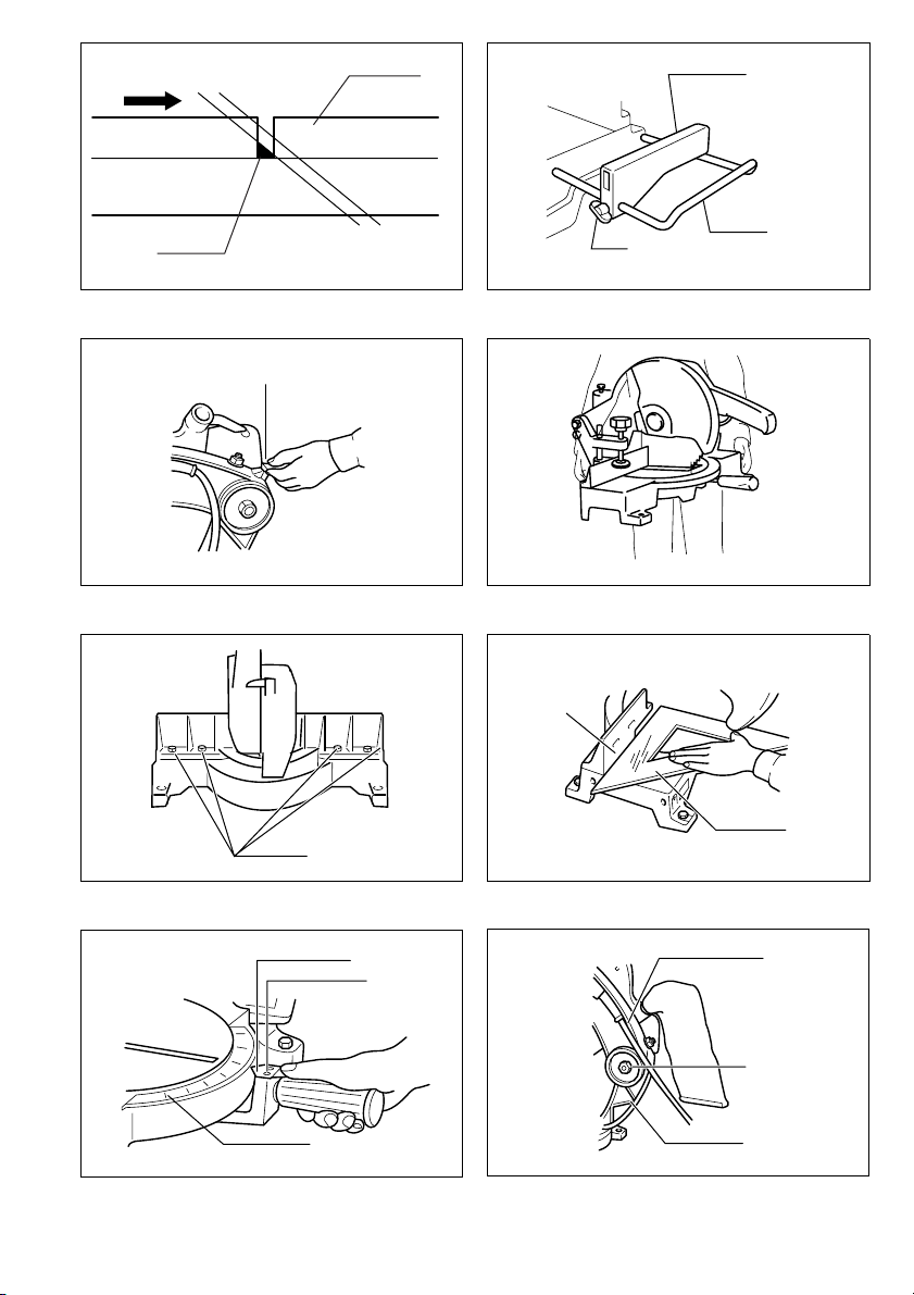
Bench mounting
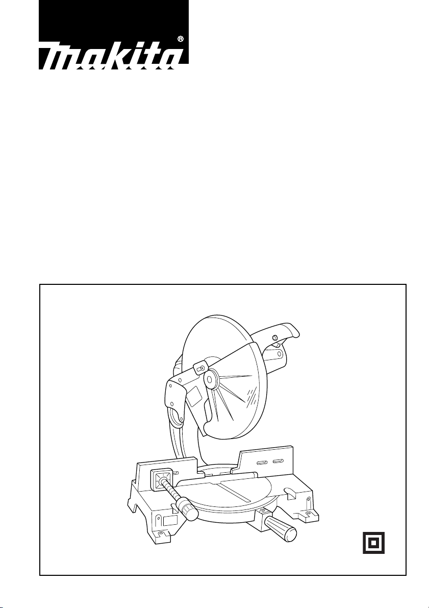
When the tool is shipped, the handle is locked in the lowered position by the handle latch. Release the handle
latch by lowering the handle slightly and turn the handle
latch to the released position. (Fig. 1)
This tool should be bolted with four bolts to a level and
stable surface using the bolt holes provided in the tool’s
base. This will help prevent tipping and possible injury.
(Fig. 2)
FUNCTIONAL DESCRIPTION
CAUTION:
• Always be sure that the tool is switched off and
unplugged before adjusting or checking function on the
tool.
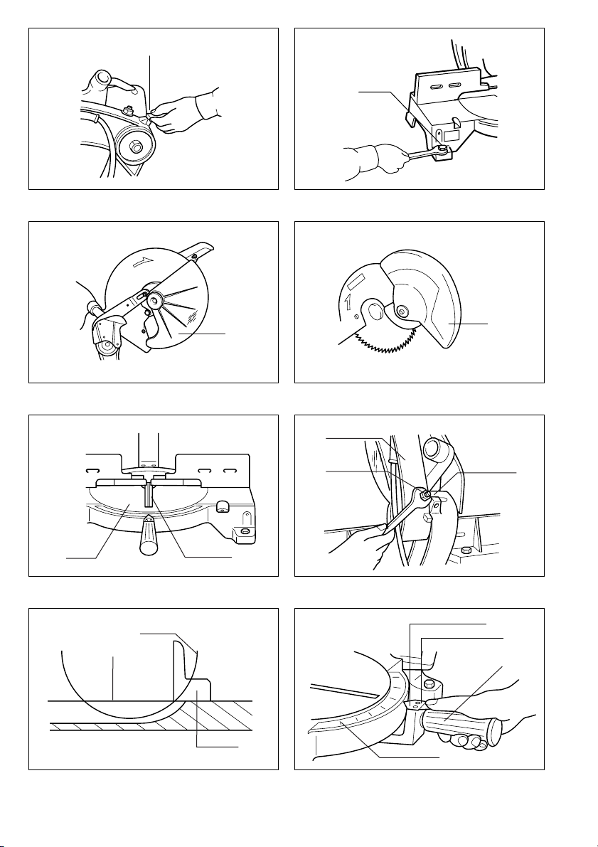
Blade guard
When lowering the handle, the blade guard rises automatically. The guard is spring loaded so it returns to its
original position when the cut is completed and the handle is raised. NEVER DEFEAT OR REMOVE THE
BLADE GUARD OR THE SPRING WHICH ATTACHES
TO THE GUARD.
In the interest of your personal safety, always maintain
the blade guard in good condition. Any irregular operation of the blade guard should be corrected immediately.
Check to assure spring loaded return action of guard.
NEVER USE THE TOOL IF THE BLADE GUARD OR
SPRING ARE DAMAGED, FAULTY OR REMOVED.
DOING SO IS HIGHLY DANGEROUS AND CAN CAUSE
SERIOUS PERSONAL INJURY.
If the see-through blade guard becomes dirty, or sawdust
adheres to it in such a way that the blade is no longer
easily visible, unplug the saw and clean the guard carefully with a damp cloth. Do not use solvents or any petroleum-based cleaners on the plastic guard.
If the blade guard is especially dirty and vision through
the guard is impaired, use the supplied socket wrench to
loosen the hex bolt holding the center cover.
Loosen the hex bolt by turning it counterclockwise and
raise the blade guard and center cover. With the blade
guard so positioned, cleaning can be more completely
and efficiently accomplished. When cleaning is complete,
reverse procedure above and secure bolt. Do not remove
spring holding blade guard. If guard becomes discolored
through age or UV light exposure, contact a Makita service center for a new guard. DO NOT DEFEAT OR
REMOVE GUARD.
(Fig. 3 & 4)
Kerf board
This tool is provided with the kerf board in the turn base
to minimize tearing on the exit side of a cut. If the kerf
groove has not yet been cut in the kerf board by the factory, you should cut the groove before actually using the
tool to cut a workpiece. Switch on the tool and lower the
blade gently to cut a groove in the kerf board.
Maintaining maximum cutting capacity
This tool is factory adjusted to provide the maximum cutting capacity for a 355 mm saw blade.
When installing a new blade, always check the lower limit
position of the blade and if necessary, adjust it as follows:
First, unplug the tool. Lower the handle completely.
Loosen the hex nut at the rear of the gear housing. Use a
screwdriver to turn the adjusting bolt until the periphery
of the blade extends slightly below the top surface of the
turn base at the point where the front face of the guide
fence meets the top surface of the turn base.
With the tool unplugged, rotate the blade by hand while
holding the handle all the way down to be sure that the
blade does not contact any part of the lower base. Readjust slightly, if necessary.
After adjusting, tighten the hex nut with the wrench while
carefully holding the adjusting bolt in position with the
screwdriver.
CAUTION:
• After installing a new blade, always be sure that the
blade does not contact any part of the lower base when
the handle is lowered completely. Always do this with
the tool unplugged.
Adjusting the miter angle
Loosen the grip by turning counterclockwise. Turn the
turn base while pressing down the lock lever. When you
have moved the grip to the position where the pointer
points to the desired angle on the miter scale, securely
tighten the grip clockwise.
CAUTION:
• When turning the turn base, be sure to raise the handle
fully.
• After changing the miter angle, always secure the turn
base by tightening the grip firmly.
Fence plate
The fence plate is designed to prevent smaller cutting
scraps from jamming inside the blade case. The fence
plate moves right or left automatically as the turn base is
rotated.
(Fig. 5)
(Fig. 6 & 7)
(Fig. 8)
Switch action (Fig. 9)
CAUTION:
• Before plugging in the tool, always check to see that
the switch trigger actuates properly and returns to the
“OFF” position when released.
To start the tool, simply pull the switch trigger. Release
the switch trigger to stop.
9
Page 10

Electric brake
This tool is equipped with an electric blade brake. If the
tool consistently fails to quickly stop blade after switch
trigger release, have tool serviced at a Makita service
center.
The blade brake system is not a substitute for blade
guard. NEVER USE TOOL WITHOUT A FUNCTIONING
BLADE GUARD. SERIOUS PERSONAL INJURY CAN
RESULT.
ASSEMBLY
CAUTION:
• Always be sure that the tool is switched off and
unplugged before carrying out any work on the tool.
Installing or removing saw blade
CAUTION:
• Always be sure that the tool is switched off and
unplugged before installing or removing the blade.
• Use only the Makita socket wrench provided to install
or remove the blade. Failure to do so may result in
overtightening or insufficient tightening of the hex bolt.
This could cause a personal injury.
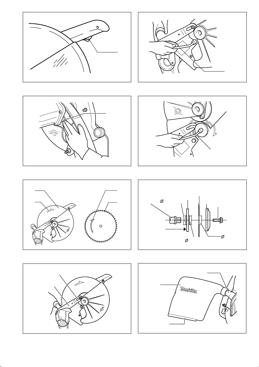
To remove the blade, use the socket wrench to loosen
the hex bolt holding the center cover by turning it counterclockwise. Raise the blade guard and center cover.
(Fig. 10)
Press the shaft lock to lock the spindle and use the
socket wrench to loosen the hex bolt clockwise. Then
remove the hex bolt, outer flange and blade. (Fig. 11 &
12)
To install the blade, mount it carefully onto the spindle,
making sure that the direction of the arrow on the surface
of the blade matches the direction of the arrow on the
blade case. Install the outer flange and hex bolt, and then
use the socket wrench to tighten the hex bolt (lefthanded) securely counterclockwise while pressing the
shaft lock. (Fig. 13 & 14)
CAUTION:
• The inner flange has a 25 mm diameter on one side
and a 25.4 mm diameter on the other. The side with
25.4 mm diameter is marked by “25.4”. Use the correct
side for the hole diameter of the blade you intend to
use. Mounting the blade on the wrong side can result in
dangerous vibration.
Slip the pin on the blade guard into the slot in the guide
arm while returning the blade guard to its original fully
closed position. Then tighten the hex bolt clockwise to
secure the center cover. Lower the handle to make sure
that the blade guard moves properly. Make sure shaft
lock has released spindle before making cut. (Fig. 15)
Dust bag
The use of the dust bag makes cutting operations clean
and dust collection easy. To attach the dust bag, fit it onto
the dust nozzle.
When the dust bag is about half full, remove the dust bag
from the tool and pull the fastener out. Empty the dust
bag of its contents, tapping it lightly so as to remove particles adhering to the insides which might hamper further
collection.
(Fig. 16)
NOTE:
• If you connect a Makita vacuum cleaner to your saw,
more efficient and cleaner operations can be performed.
Securing workpiece
Whenever possible, secure the workpiece with the
optional vise. If you must use your hand to hold the workpiece, then it must be done firmly and securely so as not
to lose control of the workpiece. Your hand and arm must
be kept well away from the blade area (100 mm minimum). Squeeze the workpiece firmly against the guide
fence with your fingers held over the top of the guide
fence. The workpiece must also rest steadily on the turn
base.
WARNING:
• Never use your hand to hold the workpiece that
requires your hand to be any closer than 100 mm from
the blade area. In this case, always use the optional
vise to secure the workpiece. After any cutting operation, raise the blade gently. Never raise the blade until it
has come to a complete stop. Serious injury may result.
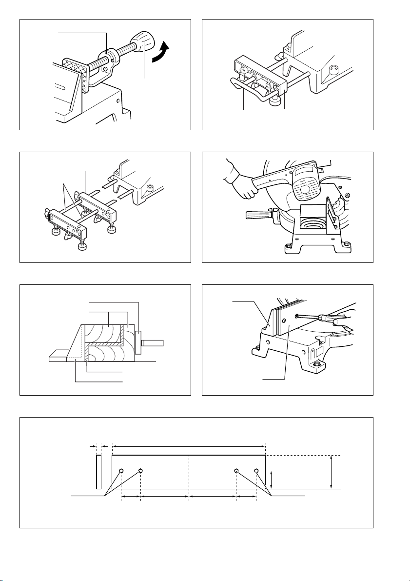
Horizontal vise (optional accessory) (Fig. 17)
The horizontal vise can be installed on either the left or
right side of the base. When performing 30° or greater
miter cuts, install the horizontal vise on the side opposite
the direction in which the turn table is to be turned. By
turning the vise knob counterclockwise, the screw is
released and the vise shaft can be moved rapidly in and
out. By turning the vise knob clockwise, the screw
remains secured. To grip the workpiece, turn the vise
knob gently clockwise until the projection reaches its topmost position, then fasten securely. If the vise knob is
forced in or pulled out while being turned clockwise, the
projection may stop at an angle. In this case, turn the
vise knob back counterclockwise until the screw is
released, before turning again gently clockwise.
CAUTION:
• Grip the workpiece only when the projection is at the
topmost position. Failure to do so may result in insufficient securing of the workpiece. This could cause the
workpiece to be thrown, cause damage to the blade or
cause the loss of control, which can result in PERSONAL INJURY.
Holders and holder assembly (optional accessories)
(Fig. 18)
The holders and the holder assembly can be installed on
either side as a convenient means of supporting workpieces horizontally. Install them as shown in Fig. 18.
Then tighten the screws firmly to secure the holders and
the holder assembly.
When cutting long workpieces, use the holder-rod
assembly (optional accessory). It consists of two holder
assemblies and two rods 12. (Fig. 19)
CAUTION:
• Always support long workpieces level with the top surface of the turn base for accurate cuts and to prevent
dangerous loss of control of the tool.
10
Page 11

OPERATION
CAUTION:
• Before use, be sure to release the handle from the lowered position by turning the handle latch to the
released position.
• Make sure the blade is not contacting the workpiece,
etc. before the switch is turned on.
• Do not apply excessive pressure on the handle when
cutting. Too much force may result in overload of the
motor and/or decreased cutting efficiency. Push down
handle with only as much force as is necessary for
smooth cutting and without significant decrease in
blade speed.
• Gently press down the handle to perform the cut. If the
handle is pressed down with force or if lateral force is
applied, the blade will vibrate and leave a mark (saw
mark) in the workpiece and the precision of the cut will
be impaired.
1. Press cutting (Fig. 20)
Secure the workpiece. Switch on the tool without the
blade making any contact and wait until the blade attains
full speed before lowering. Then gently lower the handle
to the fully lowered position to cut the workpiece. When
the cut is completed, switch off the tool and WAIT UNTIL
THE BLADE HAS COME TO A COMPLETE STOP
before returning the blade to its fully elevated position.
2. Miter cutting
Refer to the previously covered “Adjusting the miter
angle”.
3. Cutting aluminum extrusion (Fig. 21)
When securing aluminum extrusions, use spacer blocks
or pieces of scrap as shown in Fig. 21 to prevent deformation of the aluminum. Use a cutting lubricant when
cutting the aluminum extrusion to prevent buildup of the
aluminum material on the blade.
CAUTION:
• Never attempt to cut thick or round aluminum extrusions. Thick aluminum extrusions may come loose during operation and round aluminum extrusions cannot
be secured firmly with this tool.
4. Wood facing (Fig. 22, 23 & 24)
Use of wood facing helps to assure splinter-free cuts in
workpieces. Attach a wood facing to the guide fence
using the holes in the guide fence.
See Fig. 23 concerning the dimensions for a suggested
wood facing.
After changing the miter angle, cut the wood facing at
that selected angle. If there is a gap between the blade,
the wood facing and the workpiece, move the wood facing slightly in the direction of the arrow and cut it again.
CAUTION:
• Use straight wood of even thickness as the wood facing.
• Use screws to attach the wood facing to the guide
fence. The screws should be installed so that the screw
heads are below the surface of the wood facing.
• When the wood facing is attached, do not turn the turn
base with the handle lowered. The blade and/or the
wood facing will be damaged.
NOTE:
• When the wood facing is attached, the maximum cutting capacities in width will be reduced by thickness of
the wood facing.
5. Cutting repetitive lengths (Fig. 25)
When cutting several pieces of stock to the same length,
ranging from 300 mm to 400 mm, use of the set plate
(optional accessory) will facilitate more efficient operation. Install the set plate on the holder (optional accessory) as shown in Fig. 25.
Align the cutting line on your workpiece with either the
left or right side of the groove in the kerf board, and while
holding the workpiece from moving, move the set plate
flush against the end of the workpiece. Then secure the
set plate with the screw. When the set plate is not used,
loosen the screw and turn the set plate out of the way.
NOTE:
• Use of the holder-rod assembly (optional accessory)
allows cutting repetitive lengths up to 2,200 mm (7.2 ft.)
approximately.
Carrying tool
Make sure that the tool is unplugged. Secure the turn
base at right miter angle fully by means of the grip. Lower
the handle fully and lock it in the lowered position by turning the handle latch to the locked position. (Fig. 26)
Carry the tool by holding both sides of the tool base as
shown in the figure. If you remove the holders, dust bag,
etc., you can carry the tool more easily. (Fig. 27)
CAUTION:
• Always secure all moving portions before carrying the
tool.
• Handle latch is for carrying and storage purposes only
and not for any cutting operations.
MAINTENANCE
CAUTION:
• Always be sure that the tool is switched off and
unplugged before attempting to perform inspection or
maintenance.
WARNING:
• Always be sure that the blade is sharp and clean for the
best and safest performance.
Adjusting the cutting angle
This tool is carefully adjusted and aligned at the factory,
but rough handling may have affected the alignment. If
your tool is not aligned properly, perform the following:
Loosen the grip which secures the turn base. Turn the
turn base so that the pointer points to 0° on the miter
scale. Then turn the turn base slightly clockwise and
counterclockwise to seat the turn base in the 0° miter
notch. (Leave as it is if the pointer does not point to 0°.)
Loosen the hex bolts securing the guide fence using the
socket wrench. (Fig. 28)
Lower the handle fully and lock it in the lowered position
by turning the handle latch to the locked position. Square
the side of the blade with the face of the guide fence
using a triangular rule, try-square, etc. Then securely
tighten the hex bolts on the guide fence in the order from
the right side. (Fig. 29)
Make sure that the pointer on the indication plate points
to 0° on the miter scale. If the pointer does not point to
0°, loosen the screws which secure the indication plate
and adjust it so that the pointer will point to 0°. (Fig. 30)
11
Page 12

Adjusting for smooth handle action
The hex lock nut which holds the gear housing and the
arm has been factory adjusted to assure smooth handle
action up and down and to guarantee precise cutting. Do
not tamper with it. Should looseness develop at the gear
housing and arm connection, perform the following
adjustment. Work the handle up and down while tightening the hex lock nut; the best position to tighten the hex
lock nut is just before the motor body weight is obvious.
After adjusting the hex lock nut, be sure that the handle
returns automatically to the initial, raised position from
any position. If the hex lock nut is too loose, the cutting
accuracy will be affected; if it is too tight, it will be hard to
work the handle up and down. Note that this is a self
locking nut. It is a special type that does not loosen in
normal use. It should not be overtightened or replaced
with other types of nuts. (Fig. 31)
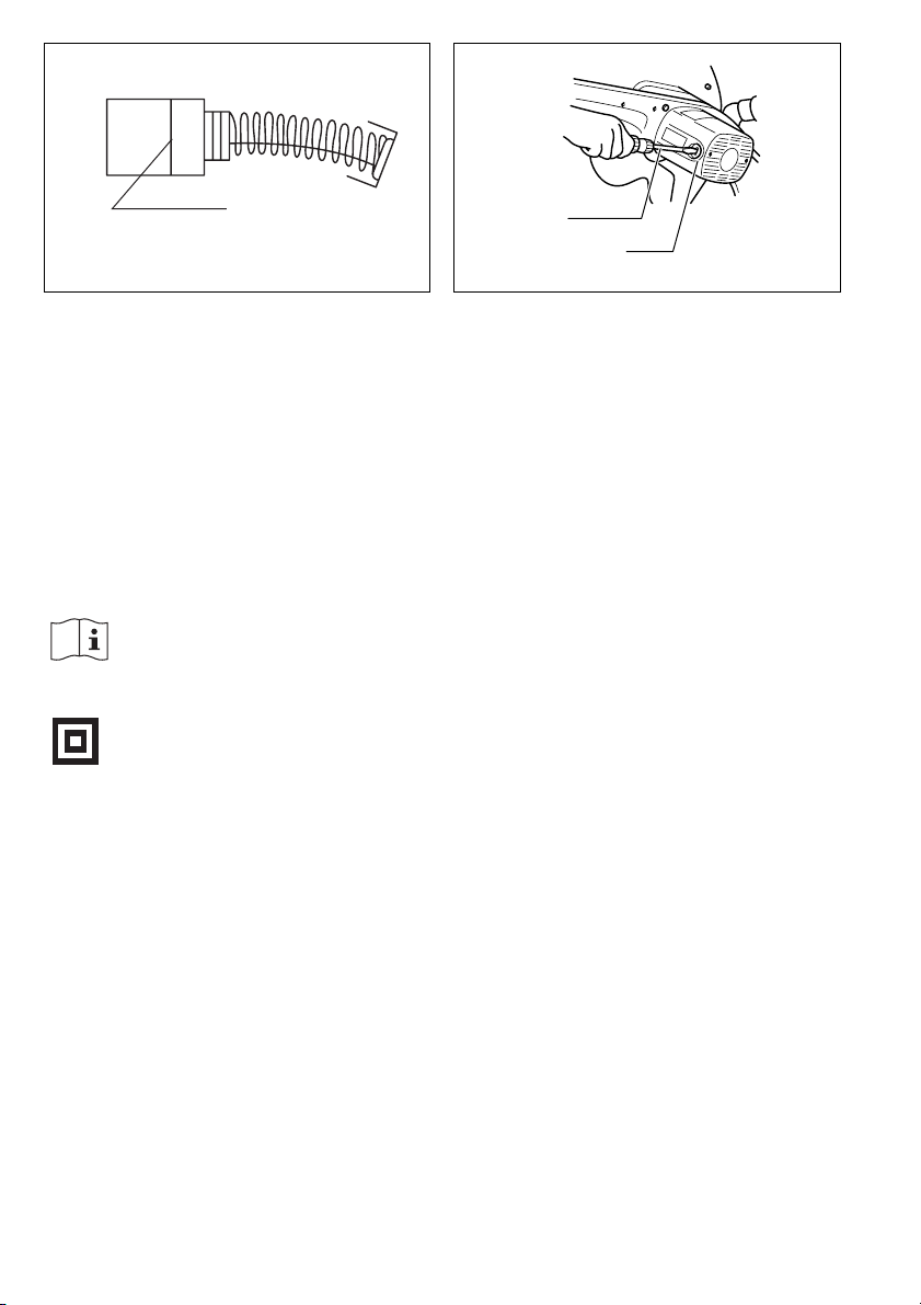
Replacing carbon brushes
Remove and check the carbon brushes regularly.
Replace when they wear down to the limit mark. Keep
the carbon brushes clean and free to slip in the holders.
Both carbon brushes should be replaced at the same
time. Use only identical carbon brushes. (Fig. 32)
Use a screwdriver to remove the brush holder caps. Take
out the worn carbon brushes, insert the new ones and
secure the brush holder caps. (Fig. 33)
After replacing brushes, plug in the tool and break in
brushes by running tool with no load for about 10 minutes. Then check the tool while running and electric
brake operation when releasing the switch trigger. If electric brake is not working well, ask your local Makita service center for repair.
After use
• After use, wipe off chips and dust adhering to the tool
with a cloth or the like. Keep the blade guard clean
according to the directions in the previously covered
section titled “Blade guard”. Lubricate the sliding portions with machine oil to prevent rust.
To maintain product SAFETY and RELIABILITY, repairs,
any other maintenance or adjustment should be performed by Makita Authorized Service Centers, always
using Makita replacement parts.
Noise and Vibration
ENG005-1
The typical A-weighted noise levels are
sound pressure level: 94 dB (A)
sound power level: 107 dB (A)
The typical weighted root mean square acceleration
value is not more than 2.5 m/s
– Wear ear protection. –
2
.
EC-DECLARATION OF CONFORMITY
We declare under our sole responsibility that this product
ENH003-1
is in compliance with the following standards of standardized documents,
EN61029, EN55014, EN61000
in accordance with Council Directives, 73/23/EEC,
89/336/EEC and 98/37/EC.
Yasuhiko Kanzaki
CE 2003
Director
MAKITA INTERNATIONAL EUROPE LTD.
Michigan Drive, Tongwell, Milton Keynes,
Bucks MK15 8JD, ENGLAND
12
Page 13

DEUTSCH
1Griffraste
2 Schraube
3 Schutzhaube
4 Drehteller
5 Schlitzplatte
6 Getriebegehäuse
7 Sechskantmutter
8 Einstellschraube
9 Drehteller-Oberfläche
10 Sägeblattumfang
11 Gehrungsanschlag
12 Zeiger
13 Rastenfeder
14 Gehrungswinkelskala
15 Griff
16 Ein-Aus-Schalter
17 Steckschlüssel
18 Spindelarretierung
19 Schutzhaube
Übersicht
20 Pfeil
21 Sägeblatt
22 Spindel
23 Innenflansch
24 Sägeblatt
25 Außenflansch
26 Sechskantschraube
27 25,4-mm-Markierung
28 Stift
29 Führungsarm
30 Absaugstutzen
31 Staubsack
32 Verschluss
33 Vorsprung
34 Schraubzwingenknopf
35 Halter
36 Auflageplatte
37 Stange 12
38 Horizontal-Schraubzwinge
39 Distanzblock
40 Aluminium-Werkstoff
41 Zwischenbrett
42 Loch
43 Werkstück
44 Es darf kein Spiel zwischen
Sägeblatt, Zwischenbrett und
Werkstück vorhanden sein.
45 Halteplatte
46 Schraube
47 Einstelldreieck
48 Schrauben
49 Sechskant-Sicherungsmutter
50 Arm
51 Verschleißgrenze
52 Schraubendreher
53 Bürstenhalterkappe
TECHNISCHE DATEN
Modell LS1440
Sägeblattdurchmesser......................................... 355 mm
Sägeblattbohrung ............................ 25 mm und 25,4 mm
Max. Gehrungswinkel .................... Links 45°, Rechts 45°
Max. Schnitttiefe (H × B)
Gehrungswinkel
0° 45° (links und rechts)
122 mm x 152 mm 122 mm x 115 mm
–1
Leerlaufdrehzahl (min
Abmessungen
(L × B × H) .........................530 mm × 596 mm × 610 mm
Nettogewicht............................................................ 34 kg
• Im Zuge unseres laufenden Forschungs- und Entwicklungsprogramms behalten wir uns das Recht vor,
Änderungen an den vorliegenden technischen Daten
ohne Vorankündigung vorzunehmen.
• Hinweis: Die technischen Daten können von Land zu
Land unterschiedlich sein.
Stromversorgung
Die Maschine darf nur an eine Einphasen-Wechselstromquelle angeschlossen werden, deren Spannung mit der
Angabe auf dem Typenschild übereinstimmt. Sie ist
gemäß der Europa-Norm doppelt schutzisoliert, und
kann daher auch mit Steckdosen ohne Erdleiter verwendet werden.
) ......................................... 3 200
SICHERHEITSHINWEISE
Achtung! Beim Gebrauch von Elektrowerkzeugen
sind zum Schutz gegen elektrischen Schlag. Verletzungsund Brandgefahr folgende grundsätzlichen Sicherheitsmaßnahmen zu geachten.
Lesen und beachten Sie diese Hinweise, bevor
Sie das Gerät benutzen.
1. Halten Sie Ihren Arbeitsbereich in Ordnung
Unordnung im Arbeitsbereich ergibt Unfallgefahr.
2. Berücksichtigen Sie Umgebungseinflüsse
Setzen sie Elektrowerkzeuge nicht dem Regen
aus. Benützen Sie Elektrowerkzeuge nicht in
feuchter oder nasser Umgebung. Sorgen Sie für
gute Beleuchtung. Benützen Sie Elektrowerkzeuge nicht in Nähe von brennbaren Flüssigkei-
ten oder Gasen.
3. Schützen Sie sich vor elektrischem Schlag
Vermeiden Sie Körperberührung mit geerdeten
Teilen, zum Beispiel Rohren, Heizkörpern, Her-
den, kühlschränken.
4. Halten Sie Kinder fern!
Lassen Sie andere Personen nicht das Werkzeug oder Kabel berühren, halten Sie sie von
Ihrem Arbeitsbereich fern.
5. Bewahren Sie Ihre Werkzeuge sicher auf
Unbenutzte Werkzeuge sollten in trockenem,
verschlossenem Raum und für Kinder nicht
erreichbar aufbewahrt werden.
6. Überlasten Sie Ihr Werkzeug nicht
Sie arbeiten besser und sicherer im angegebenen Leistungsbereich.
7. Benützen Sie das richtige Werkzeug
Verwenden Sie keine zu schwachen Werkzeuge
oder Vorsatzgeräte für schwere Arbeiten.
Benützen Sie Werkzeuge nicht für Zwecke und
Arbeiten, Wofür sie nicht bestimmt sind; zum
Beispiel benützen Sie keine Handkreissäge, um
Bäume zu flällen oder Äste zu schneiden.
13
Page 14

8. Tragen Sie geeignete Arbeitskleidung
Tragen Sie keine weite Kleidung oder Schmuck.
Sie können von beweglichen Teilen erfaßt werden. Bei Arbeiten im Freien sind Gummihandschuhe und rutschfestes Schuhwerk
empfehlenswert. Tragen Sie bei langen Haaren
ein Haarnetz.
9. Schutzbrille und Gehörschutz tragen
Verwenden Sie eine Atemmaske bei stauberzeugenden Arbeiten.
10. Schlleßen Sie eine Staubabsaugvorrichtung
an
Wenn Geräte für den Anschluß von Staubabsaug-und-sammelvorrichtungen ausgelegt sind,
sorgen Sie dafür, daß Jiese angeschlossen und
korrekt benutzi werden.
11. Zweckentfremden Sie nicht das Kabel
Tragen Sie das Werkzeug nicht am Kabel, und
benützen Sie es nicht, um den Stecker aus der
Steckdose zu ziehen. Schützen Sie das Kabel
vor Hitze, Öl und scharfen Kanten.
12. Sichern Sie das Werkstück
Benützen Sie Spannvorrichtungen oder einen
Schraubstock, um das Werkstück festzuhalten.
Es ist damit sicherer gehalten als mit Ihrer Hand
und ermöglicht die Bedienung der Maschine mit
beiden Händen.
13. Überdehnen Sie nicht Ihren Standbereich
Vermeiden Sie abnormale Körperhaltung. Sorgen Sie für sicheren Stand, und halten Sie jederzeit das Gleichgewicht.
14. Pflegen Sie Ihre Werkzeuge mit Sorgtalt
Halten Sie Ihre Werkzeuge scharf und sauber,
um gut und sicher zu arbeiten. Befolgen Sie die
Wartungsvorschriften und die Hinweise für
Werkzeugwechsel. Kontrollieren Sie regelmäßig
den Stecker und das Kabel, und lassen Sie
diese bei Beschädigung von einem anerkannten
Fachmann erneuern.
Kontrollieren Sie Verlängerungskabel regelmä-
ßig und ersetzen Sie beschädigte. Halten Sie
Handgriffe trocken und frei von Öl und Fett.
15. Ziehen Sie den Netzstecker
Bei Nichtgebrauch, vor der Wartung und beim
Werkzeugwechsel, wie zum Beispiel Sägeblatt,
Bohrer und Maschinenwerkzeugen aller Art.
16. Lassen Sie keine Werkzeugschlüssel stecken
Überprüfen Sie vor dem Einschalten, daß die
Schlüssel und Einstellwerkzeuge entfernt sind.
17. Vermeiden Sie unbeabsichtigten Anlauf
Tragen Sie keine an das Stromnetz angeschlossene Werkzeuge mit dem Finger am Schalter.
Vergewissern Sie sich, daß der Schalter beim
Anschluß an das Stromnetz ausgeschaltet ist.
18. Verlängerungskabel im Freien
Verwenden Sie im Freien nur dafür zugelassene
und entsprechend gekennzeichnete Varlänge-
rungskabel.
19. Seien Sie stets aufmerksam
Beobachten Sie Ihre Arbeit. Gehen Sie vernünf-
tig vor. Verwenden Sie das Werkzeug nicht,
wenn Sie unkonzentriert sind.
20. Kontrollieren Sie Ihr Gerät auf Beschädigungen
Vor weiterem Gebrauch des Werkzeugs die
Schutzeinrichtungen oder leicht beschädigte
Teile sorgfältig auf ihre einwandfreie und bestimmungsgemäße Funktion überprüfen. Überprü-
fen Sie, ob die Funktion beweglicher Teile in
Ordnung ist, ob sie nicht klemmen onder ob Teile
beschädigt sind. Sämtliche Teile müssen richtig
montiert sein und alle Bedingungen erfüllen, um
den einwandfreien Betrieb des Gerätes zu
gewährleisten.
Beschädigte Schutzvorrichtungen und Teile sollen sachgemäß durch eine Kundendienstwerkstatt repariert oder ausgewechselt werden,
soweit nichts anderes in den Betriebsanleitungen angegeben ist. Beschädigte Schalter müs-
sen bei einer Kundendienstwerkstatt ersetzt
werden. Benutzen Sie keine Werkzeuge, bei
denen sich der Schalter nicht ein und ausschalten läßt.
21. Achtung!
Zu Ihrer eigenen Sicherheit, benützen Sie nur
Zubehör und Zusatzgeräte, die in der Bedienungsanleitung angegeben oder vom WerkzeugHersteller empfohlen oder angegeben werden.
Der Gebrauch anderer als der in der Bedienungsanleitung oder im Katalog empfohlenen
Einsatzwerkzeuge oder Zubehöre kann eine persönliche Verletzungsgefahr für Sie bedeuten.
22. Reparaturen nur vom Elektrofachmann.
Dieses Elektrowerkzeug entspricht den einschlä-
gigen Sicherheitsbestimmungen. Reparaturen
dürfen nur von einer Elektrofachkraft ausgeführt
werden, andernfalls können Unfälle für den
Betreiber entstehen.
ZUSÄTZLICHE SICHERHEITSREGELN FÜR
DIE MASCHINE
1. Tragen Sie stets eine Schutzbrille.
2. Halten Sie Ihre Hände von der Schnittlinie des
Sägeblatts fern. Vermeiden Sie die Berührung
eines auslaufenden Sägeblatts. Es kann auch in diesem Zustand noch schwere Verletzungen verursachen.
3. Betreiben Sie die Säge nicht ohne Schutzvorrichtungen. Überprüfen Sie die Schutzhaube vor
jeder Benutzung auf einwandfreies Schließen.
Betreiben Sie die Säge nicht, wenn sich die
Schutzhaube nicht ungehindert bewegt und sich
nicht sofort schließt. Die Schutzhaube darf auf
keinen Fall in der geöffneten Stellung festgeklemmt oder festgebunden werden.
4. Führen Sie keine freihändigen Arbeiten aus.
5. Fassen Sie niemals um das Sägeblatt.
6. Schalten Sie die Maschine aus und lassen Sie
das Sägeblatt zum Stillstand kommen, bevor Sie
das Werkstück bewegen oder Einstellungen
ändern.
7. Trennen Sie die Maschine vom Stromnetz, bevor
Sie das Sägeblatt wechseln oder die Maschine
warten.
14
Page 15

8. Betreiben Sie die Maschine nicht in Gegenwart von
brennbaren Flüssigkeiten oder Gasen.
9. Überprüfen Sie das Sägeblatt vor dem Betrieb sorg-
fältig auf Risse oder Beschädigung.
Wechseln Sie ein gerissenes oder beschädigtes
Sägeblatt unverzüglich aus.
10. Verwenden Sie nur die für diese Maschine vorge-
schriebenen Flansche.
11. Achten Sie sorgfältig darauf, dass Achse, Flansche
(insbesondere die Ansatzfläche) und Schraube nicht
beschädigt werden. Eine Beschädigung dieser Teile
kann zu einem Sägeblattbruch führen.
12. Vergewissern Sie sich, dass der Drehteller einwand-
frei gesichert ist, damit er sich während des Betriebs
nicht bewegt.
13. Zur Sicherheit sollte die Tischplatte vor dem Betrieb
von Spänen, Kleinteilen usw. gesäubert werden.
14. Schneiden Sie keine Nägel durch. Untersuchen Sie
das Werkstück sorgfältig auf Nägel, und entfernen
Sie diese vor der Bearbeitung.
15. Vergewissern Sie sich vor dem Einschalten der
Maschine, dass die Spindelarretierung freigegeben
ist.
16. Vergewissern Sie sich, dass das Sägeblatt in der
Tiefstellung nicht mit dem Drehteller in Berührung
kommt.
17. Halten Sie den Handgriff sicher fest. Beachten Sie,
dass sich die Säge beim Anlaufen und Abstellen
geringfügig nach oben oder unten bewegt.
18. Vergewissern Sie sich vor dem Einschalten der
Maschine, dass das Sägeblatt nicht das Werkstück
berührt.
19. Lassen Sie die Maschine vor dem eigentlichen
Schneiden eines Werkstücks eine Weile laufen.
Achten Sie auf Vibrationen oder Taumelbewegungen, die Anzeichen für schlechte Montage oder ein
schlecht ausgewuchtetes Sägeblatt sein können.
20. Warten Sie, bis das Sägeblatt die volle Drehzahl
erreicht hat, bevor Sie mit dem Schneiden beginnen.
21. Brechen Sie sofort den Betrieb ab, wenn Sie irgend-
etwas Ungewöhnliches bemerken.
22. Versuchen Sie nicht, den Schalter in der Einschalt-
stellung zu arretieren.
23. Seien Sie stets wachsam, besonders bei sich dau-
ernd wiederholenden, eintönigen Arbeiten. Lassen
Sie sich nicht in trügerische Sicherheit wiegen.
Sägeblätter kennen kein Erbarmen.
24. Verwenden Sie stets das in dieser Anleitung
empfohlene Zubehör. Der Gebrauch ungeeigneten Zubehörs, wie z.B. Schleifscheiben, kann
Verletzungen zur Folge haben.
25. Benutzen Sie die Säge nur zum Schneiden von
Aluminium, Holz oder ähnlichem Material.
26. Schließen Sie Gehrungs- und Kappsägen beim
Betrieb an eine Staubsammelvorrichtung an.
27. Wählen Sie die Sägeblätter unter Berücksichtigung des zu schneidenden Materials aus.
28. Lassen Sie beim Nutenschneiden Vorsicht walten.
29. Wechseln Sie die Schlitzplatte bei Verschleiß
aus.
BEWAHREN SIE DIESE HINWEISE
SORGFÄLTIG AUF.
MONTAGE
Befestigung der Säge auf einer Werkbank
Der Handgriff wurde werksseitig vor dem Versand mit der
Griffraste in der Tiefstellung verriegelt. Lösen Sie die
Griffraste, indem Sie den Handgriff leicht nach unten
drücken und die Griffraste auf die Freigabestellung drehen. (Abb. 1)
Diese Maschine sollte unter Verwendung der Schraubenbohrungen in der Grundplatte mit vier Schrauben auf
einer ebenen und stabilen Oberfläche befestigt werden.
Dadurch werden Umkippen und mögliche Verletzungen
vermieden. (Abb. 2)
FUNKTIONSBESCHREIBUNG
VORSICHT:
• Vergewissern Sie sich vor jeder Einstellung oder Funktionsprüfung der Maschine stets, dass sie ausgeschaltet und vom Stromnetz getrennt ist.
Schutzhaube (Abb. 3 u. 4)
Wird der Handgriff abgesenkt, hebt sich die Schutzhaube
automatisch. Die Schutzhaube ist gefedert, so dass sie
in ihre Ausgangsstellung zurückkehrt, wenn der Schnitt
vollendet ist und der Handgriff angehoben wird. NIEMALS DIE SCHUTZHAUBE ODER DIE DARAN ANGEBRACHTE FEDER FUNKTIONSUNFÄHIG MACHEN
ODER ENTFERNEN.
Im Interesse Ihrer eigenen Sicherheit sollten Sie die
Schutzhaube stets in ordnungsgemäßem Zustand halten. Funktionsstörungen der Schutzhaube müssen sofort
behoben werden. Überprüfen Sie die gefederte Rückkehrbewegung der Schutzhaube. BENUTZEN SIE DIE
MASCHINE NIEMALS MIT BESCHÄDIGTER, DEFEKTER ODER FEHLENDER SCHUTZHAUBE ODER
FEDER, WEIL DIES SEHR GEFÄHRLICH IST UND ZU
SCHWEREN VERLETZUNGEN FÜHREN KANN.
Wenn die transparente Schutzhaube schmutzig wird
oder soviel Sägemehl an ihr haftet, dass das Sägeblatt
nicht mehr ohne weiteres sichtbar ist, sollten Sie die
Maschine vom Stromnetz trennen und die Schutzhaube
mit einem feuchten Tuch sorgfältig reinigen. Verwenden
Sie keine Lösungsmittel oder Reinigungsmittel auf Petroleumbasis zum Reinigen der Kunststoff-Schutzhaube.
Wenn bei besonders starker Verschmutzung der Schutzhaube die Sicht durch die Schutzhaube behindert ist,
lösen Sie die Sechskantschraube, mit der die Mittenabdeckung befestigt ist, mit dem mitgelieferten Steckschlüssel.
Lösen Sie die Sechskantschraube durch Drehen entgegen dem Uhrzeigersinn, und heben Sie die Schutzhaube
und die Mittenabdeckung an. In dieser Stellung der
Schutzhaube kann die Reinigung gründlicher und effizienter durchgeführt werden. Wenden Sie nach der Reinigung das obige Demontageverfahren umgekehrt an, und
ziehen Sie die Schraube an. Entfernen Sie nicht die
Feder, welche die Schutzhaube hält. Falls sich die
Schutzhaube durch Alterung oder UV-Strahlung verfärbt,
bestellen Sie eine neue Schutzhaube bei einer MakitaKundendienststelle. DIE SCHUTZHAUBE DARF NICHT
FUNKTIONSUNFÄHIG GEMACHT ODER ENTFERNT
WERDEN.
15
Page 16

Schlitzplatte (Abb.5)
Diese Maschine ist mit einer Schlitzplatte im Drehteller
versehen, um Reißen am Austrittsende eines Schnitts
auf ein Minimum zu reduzieren. Falls der Einschnitt nicht
bereits werkseitig ausgeführt wurde, müssen Sie den
Schlitz schneiden, bevor Sie die Maschine zum tatsächli-
chen Sägen eines Werkstücks verwenden. Schalten Sie
die Maschine ein, und senken Sie das Sägeblatt vorsichtig ab, um einen Schlitz in die Schlitzplatte zu schneiden.
Aufrechterhaltung der maximalen Schnittleistung
(Abb. 6 u. 7)
Diese Maschine wurde werkseitig so eingestellt, dass die
maximale Schnittleistung mit einem Sägeblatt von
355 mm Durchmesser erreicht wird.
Wenn Sie ein neues Sägeblatt montieren, überprüfen Sie
immer die untere Grenzposition des Sägeblatts, und nehmen Sie nötigenfalls eine Einstellung vor, wie folgt:
Ziehen Sie zuerst den Netzstecker ab. Senken Sie den
Handgriff völlig ab. Lösen Sie die Sechskantmutter auf
der Rückseite des Getriebegehäuses. Drehen Sie die
Einstellschraube mit einem Schraubenzieher, bis der
Sägeblattumfang am Berührungspunkt von Gehrungsanschlag-Vorderseite und Drehteller-Oberfläche geringfü-
gig unterhalb der Drehteller-Oberfläche liegt.
Drehen Sie das Sägeblatt bei vom Stromnetz getrennter
Maschine von Hand, während Sie den Handgriff in der
Tiefstellung halten, um sicherzugehen, dass das Säge-
blatt keinen Teil des Auflagetisches berührt. Nötigenfalls
ist eine Nachjustierung vorzunehmen.
Ziehen Sie die Sechskantmutter nach der Einstellung mit
dem Steckschlüssel an, während Sie die Einstellschraube mit dem Schraubenzieher einwandfrei festhalten.
VORSICHT:
• Vergewissern Sie sich nach der Montage eines neuen
Sägeblatts stets, dass das Sägeblatt in der Tiefstellung
des Handgriffs keinen Teil des Auflagetisches berührt.
Führen Sie diese Überprüfung immer bei abgezogenem Netzstecker durch.
Einstellung des Gehrungswinkels (Abb. 8)
Lösen Sie den Griff durch Linksdrehung. Drehen Sie den
Drehteller, während Sie den Arretierhebel niederdrücken.
Bewegen Sie den Griff, bis der Zeiger auf den gewünsch-
ten Winkel der Gehrungswinkelskala zeigt, und ziehen
Sie dann den Griff durch Rechtsdrehung fest.
VORSICHT:
• Bringen Sie den Handgriff in die Hochstellung, bevor
Sie den Drehteller drehen.
• Sichern Sie den Drehteller nach jeder Änderung des
Gehrungswinkels stets durch Anziehen des Griffs
gegen Verdrehen.
Anschlagplatte
Die Anschlagplatte soll verhindern, dass sich kleine
Späne in der Schutzhaube ansammeln. Die Anschlagplatte bewegt sich automatisch nach rechts oder links,
wenn der Drehteller gedreht wird.
Schalterfunktion (Abb. 9)
VORSICHT:
• Vergewissern Sie sich vor dem Anschließen der
Maschine an das Stromnetz stets, dass der Ein-AusSchalter ordnungsgemäß funktioniert und beim Loslassen in die AUS-Stellung zurückkehrt.
Zum Einschalten der Maschine einfach den Ein-AusSchalter drücken. Zum Ausschalten den Ein-Aus-Schalter loslassen.
Elektrische Bremse
Diese Maschine ist mit einer elektrischen Sägeblatt-
bremse ausgestattet. Falls die Maschine nach dem Loslassen des Ein-Aus-Schalters nicht sofort anhält, lassen
Sie sie von einer Makita-Kundendienststelle warten.
Das Sägeblatt-Bremssystem ist kein Ersatz für die
Schutzhaube. BENUTZEN SIE DIE MASCHINE NIEMALS OHNE EINE FUNKTIONSFÄHIGE SCHUTZHAUBE, WEIL ES SONST ZU SCHWEREN
VERLETZUNGEN KOMMEN KANN.
MONTAGE
VORSICHT:
• Vergewissern Sie sich vor der Ausführung von Arbeiten
an der Maschine stets, dass sie ausgeschaltet und vom
Stromnetz getrennt ist.
Montage und Demontage des Sägeblatts
VORSICHT:
• Vergewissern Sie sich vor der Montage bzw. Demontage des Sägeblatts stets, dass die Maschine ausgeschaltet und vom Stromnetz getrennt ist.
• Verwenden Sie nur den mitgelieferten Makita-Steckschlüssel zum Demontieren oder Montieren des Sägeblatts. Anderenfalls besteht die Gefahr, dass die
Sechskantschraube zu stark oder zu schwach angezogen wird. Dies könnte zu einer Verletzung führen.
Zum Demontieren des Sägeblatts lösen Sie zunächst die
Sechskantschraube, mit der die Mittenabdeckung befestigt ist, durch Linksdrehung mit dem Steckschlüssel.
Heben Sie die Schutzhaube und die Mittenabdeckung
an. (Abb.10)
Blockieren Sie die Spindel durch Drücken der Spindelarretierung, und lösen Sie die Sechskantschraube (linksgängig) durch Rechtsdrehung des Steckschlüssels.
Nehmen Sie dann Sechskantschraube, Außenflansch
und Sägeblatt ab. (Abb.11 u. 12)
Zum Montieren schieben Sie das Sägeblatt vorsichtig auf
die Spindel, wobei Sie darauf achten, dass der Pfeil auf
dem Sägeblatt in dieselbe Richtung zeigt wie der Pfeil
auf dem Sägeblattgehäuse. Bringen Sie Außenflansch
und Sechskantschraube an, und ziehen Sie dann die
Sechskantschraube (linksgängig) bei gedrückter Spindelarretierung durch Linksdrehung des Steckschlüssels
fest. (Abb.13 u. 14)
VORSICHT:
• Der Innenflansch hat einen Durchmesser von 25 mm
auf der einen, und von 25,4 mm auf der anderen Seite.
Die Seite mit 25,4 mm Durchmesser ist mit “25.4” markiert. Verwenden Sie die für die Bohrung des zu benutzenden Sägeblatts passende Seite. Die Montage des
Sägeblatts auf der falschen Seite kann zu gefährlichen
Vibrationen führen.
16
Page 17

Schieben Sie den Stift an der Schutzhaube in den Schlitz
am Führungsarm, während Sie die Schutzhaube auf die
völlig geschlossene Stellung zurückführen. Ziehen Sie
dann die Sechskantschraube zur Sicherung der Mittenabdeckung im Uhrzeigersinn an. Senken Sie den Handgriff ab, um zu prüfen, ob sich die Schutzhaube
einwandfrei bewegt. Vergewissern Sie sich vor der
Benutzung der Maschine, dass die Spindelarretierung
gelöst ist. (Abb. 15)
Staubsack (Abb.16)
Der Staubsack ermöglicht sauberes Arbeiten und einfaches Staubsammeln. Zum Anbringen wird der Staubsack
auf den Absaugstutzen geschoben.
Wenn der Staubsack etwa halb voll ist, nehmen Sie ihn
von der Maschine ab und ziehen den Verschluss heraus.
Entleeren Sie den Staubsack, indem Sie ihn leicht
abklopfen, um die an den Innenflächen haftenden Staubpartikel, die den Durchlass behindern können, zu lösen.
HINWEIS:
• Wenn Sie einen Makita-Staubsauger an Ihre Säge
anschließen, können Sie noch effizienter und sauberer
arbeiten.
Sicherung von Werkstücken
Spannen Sie das Werkstück nach Möglichkeit in die
optionale Schraubzwinge ein. Wenn Sie das Werkstück
mit der Hand halten müssen, halten Sie es mit festem
Griff, damit Sie nicht die Kontrolle über das Werkstück
verlieren. Halten Sie Hand und Arm vom Sägeblattbe-
reich fern (mindestens 100 mm). Drücken Sie das Werkstück fest gegen den Gehrungsanschlag, indem Sie mit
Ihren Fingern über den Gehrungsanschlag greifen. Das
Werkstück muss auch fest auf dem Drehteller aufliegen.
WARNUNG:
• Halten Sie ein Werkstück, bei dem Ihre Hand näher als
100 mm an den Sägeblattbereich herankommt, niemals mit der Hand. Sichern Sie das Werkstück in diesem Fall immer mit der optionalen Schraubzwinge.
Heben Sie das Sägeblatt nach jedem Schneidvorgang
sachte an. Heben Sie das Sägeblatt erst an, nachdem
es zum völligen Stillstand gekommen ist. Anderenfalls
kann es zu schweren Verletzungen kommen.
Horizontal-Schraubzwinge (Sonderzubehör)
(Abb. 17)
Die Horizontal-Schraubzwinge kann entweder auf der linken oder rechten Seite des Auflagetisches montiert werden. Wenn Gehrungsschnitte in einem Winkel von 30°
oder mehr ausgeführt werden, ist die HorizontalSchraubzwinge auf der entgegengesetzten Seite der
Drehteller-Drehrichtung zu montieren. Durch Linksdrehung des Schraubzwingenknopfes wird die Schraube
gelöst, so dass der Schraubzwingenschaft schnell vorund zurückgeschoben werden kann. Durch Rechtsdrehen des Schraubzwingenknopfes bleibt die Schraube
gesichert. Drehen Sie den Schraubzwingenknopf zum
Einspannen von Werkstücken sachte im Uhrzeigersinn,
bis der Vorsprung seine Höchstposition erreicht, und ziehen Sie ihn dann fest. Wird der Schraubzwingenknopf
während der Rechtsdrehung hineingedrückt oder herausgezogen, bleibt der Vorsprung eventuell schräg stehen. Drehen Sie den Schraubzwingenknopf in diesem
Fall entgegen dem Uhrzeigersinn zurück, bis sich die
Schraube löst, bevor Sie ihn wieder sachte im Uhrzeigersinn drehen.
VORSICHT:
• Spannen Sie das Werkstück nur ein, wenn sich der
Vorsprung an der obersten Position befindet. Anderenfalls wird das Werkstück möglicherweise nicht ausreichend gesichert, so dass die Gefahr besteht, dass es
herausgeschleudert, das Sägeblatt beschädigt oder
Verlust der Kontrolle verursacht wird, was zu VERLETZUNGEN führen kann.
Auflagebügel und Auflageplatte (Sonderzubehör)
(Abb.18)
Die Auflagebügel und Auflageplatten können zur zusätz-
lichen Abstützung von Werkstücken auf beiden Seiten
montiert werden. Montieren Sie die Teile, wie in Abb. 18
gezeigt. Ziehen Sie dann die Schrauben fest, um Auflagebügel und Auflageplatte zu sichern.
Wenn Sie lange Werkstücke sägen, verwenden Sie den
Auflageverlängerungssatz (Sonderzubehör). Dieser best
eht aus zwei Auflageplatten und zwei Stangen 12.
(Abb. 19)
VORSICHT:
• Lange Werkstücke müssen stets auf gleicher Höhe mit
der Drehteller-Oberfläche abgestützt werden, um
genaue Schnitte auszuführen und gefährlichen Verlust
der Kontrolle über die Maschine zu vermeiden.
BETRIEB
VORSICHT:
• Lösen Sie den Handgriff vor der Benutzung aus der
Tiefstellung, indem Sie die Griffraste auf die Freigabestellung drehen.
• Vergewissern Sie sich vor dem Einschalten der
Maschine, dass das Sägeblatt nicht das Werkstück
usw. berührt.
•Üben Sie beim Schneiden keinen übermäßigen Druck
auf den Handgriff aus. Zu starker Druck kann zu Über-
lastung des Motors und/oder verminderter Schnittleistung führen. Drücken Sie den Handgriff nur mit soviel
Kraft nieder, wie für reibungslosen Sägebetrieb notwendig ist, ohne einen beträchtlichen Abfall der Säge-
blattdrehzahl zu verursachen.
• Drücken Sie den Handgriff zur Ausführung des Schnitts
sachte nieder. Bei zu großer oder seitlicher Kraftausübung kann das Sägeblatt in Schwingung versetzt werden, wodurch zusätzliche Sägespuren im Werkstück
erzeugt werden und die Schnittgenauigkeit beeinträch-
tigt wird.
1. Kappschnitt (Abb.20)
Sichern Sie das Werkstück. Schalten Sie die Maschine
ein, ohne dass das Sägeblatt Kontakt hat, und warten
Sie, bis es seine volle Drehzahl erreicht, bevor Sie es
absenken. Senken Sie dann den Handgriff zum Schneiden des Werkstücks sachte bis auf die Tiefstellung ab.
Sobald der Schnitt beendet ist, schalten Sie die
Maschine aus und WARTEN, BIS DAS SÄGEBLATT
ZUM VÖLLIGEN STILLSTAND GEKOMMEN IST, bevor
Sie den Sägekopf wieder ganz anheben.
2. Gehrungsschnitt
Siehe den vorhergehenden Abschnitt “Einstellung des
Gehrungswinkels”.
17
Page 18

3. Schneiden von Aluminium-Strangpressprofilen
(Abb.21)
Verwenden Sie zum Einspannen von Aluminium-Strangpressprofilen Distanzblöcke oder Abfallholzstücke, wie in
Abb. 21 gezeigt, um eine Verformung des Aluminiums zu
vermeiden. Verwenden Sie Schneidflüssigkeit zum
Schneiden von Aluminium-Strangpressprofilen, um die
Ablagerung von Aluminium-Rückständen am Sägeblatt
zu verhüten.
VORSICHT:
• Versuchen Sie niemals, dicke oder runde Aluminium-
Strangpressprofile zu schneiden. Dicke AluminiumStrangpressprofile können sich während der Arbeit
lösen, und runde Aluminium-Strangpressprofile lassen
sich mit dieser Maschine nicht einwandfrei einspannen.
4. Zwischenbrett (Abb. 22, 23 u. 24)
Durch die Verwendung eines Zwischenbretts lassen sich
Werkstücke splitterfrei sägen. Die Bohrungen im Gehrungsanschlag dienen als Befestigungshilfe für ein Zwischenbrett.
Die Maße für ein vorgeschlagenes Zwischenbrett sind
aus Abb. 23 ersichtlich.
Schneiden Sie das Holz nach einer Änderung des Gehrungswinkels so, dass es auf den gewählten Winkel ausgerichtet ist. Falls eine Lücke zwischen Sägeblatt,
Zwischenbrett und Werkstück vorhanden ist, verschieben
Sie das Zwischenbrett geringfügig in Pfeilrichtung, bevor
Sie einen erneuten Schnitt ausführen.
VORSICHT:
• Verwenden Sie glatt gehobeltes Holz von gleichmäßi-
ger Dicke als Zwischenbrett.
• Befestigen Sie das Zwischenbrett mit Schrauben am
Gehrungsanschlag. Die Schrauben sind so zu installieren, dass die Schraubenköpfe im Zwischenbrett versenkt sind.
• Drehen Sie den Drehteller bei montiertem Zwischen-
brett nicht mit abgesenktem Handgriff. Anderenfalls
kommt es zu einer Beschädigung des Sägeblatts und/
oder des Zwischenbretts.
HINWEIS:
• Wenn ein Zwischenbrett eingespannt wird, verringert
sich die maximale Schnittkapazität um die Dicke des
Zwischenbretts.
5. Wiederholtes Schneiden auf gleiche Länge
(Abb.25)
Wenn Sie mehrere Werkstücke innerhalb des Bereichs
von 300 bis 400 mm auf die gleiche Länge schneiden, ist
die Verwendung der Anschlagplatte (Sonderzubehör) zu
empfehlen, um rationeller zu arbeiten. Montieren Sie die
Anschlagplatte am Auflagebügel (Sonderzubehör), wie in
Abb. 25 gezeigt.
Richten Sie die Schnittlinie des Werkstücks entweder auf
die linke oder rechte Kante der Nut in der Schlitzplatte
aus, und schieben Sie die Anschlagplatte bündig gegen
das Ende des Werkstücks, während Sie das Werkstück
am Verrutschen hindern. Sichern Sie dann die Anschlagplatte mit der Flügelschraube. Wenn Sie die Anschlagplatte nicht benutzen, lösen Sie die Flügelschraube, um
die Anschlagplatte zur Seite zu schieben.
HINWEIS:
• Der Auflageverlängerungssatz (Sonderzubehör) ermög-
licht das wiederholte Schneiden auf gleiche Längen von
bis zu etwa 2 200 mm.
Tragen der Maschine
Vergewissern Sie sich, dass der Netzstecker abgezogen
ist. Sichern Sie den Drehteller mit dem Griff im rechten
Gehrungswinkel. Senken Sie den Handgriff völlig ab, und
sichern Sie ihn in der Tiefstellung, indem Sie die
Griffraste auf die Verriegelungsstellung drehen. (Abb.
26)
Tragen Sie die Maschine, indem Sie die Grundplatte auf
beiden Seiten halten, wie in der Abbildung gezeigt. Die
Maschine lässt sich bequemer tragen, wenn Auflagebü-
gel, Staubsack usw. entfernt werden. (Abb. 27)
VORSICHT:
• Sichern Sie stets alle beweglichen Teile, bevor Sie die
Maschine tragen.
• Die Griffraste ist nur zum Tragen und zur Lagerung,
nicht für irgendwelche Schneidarbeiten, vorgesehen.
WARTUNG
VORSICHT:
• Denken Sie vor der Durchführung von Überprüfungen
oder Wartungsarbeiten stets daran, die Maschine auszuschalten und vom Stromnetz zu trennen.
WARNUNG:
• Achten Sie stets darauf, dass das Sägeblatt scharf und
sauber ist, um die bestmögliche und sicherste Leistung
zu erzielen.
Einstellen des Schnittwinkels
Diese Maschine wurde werkseitig sorgfältig eingestellt
und justiert, doch grobe Behandlung kann die Justierung
beeinträchtigen. Sollte Ihre Maschine einer Nachjustierung bedürfen, gehen Sie folgendermaßen vor: Lösen
Sie den Spanngriff, mit dem der Drehteller gesicher t
wird. Drehen Sie dann den Drehteller, so dass der Zeiger
auf 0° auf der Gehrungswinkelskala zeigt. Bewegen Sie
dann den Drehteller geringfügig nach links und rechts,
bis er einwandfrei in der 0°-Gehrungswinkelraste sitzt.
(Lassen Sie den Drehteller unverändert, falls der Zeiger
nicht auf 0° zeigt.) Lösen Sie die Sechskantschrauben,
die den Gehrungsanschlag halten, mit dem Steckschlüs-
sel. (Abb. 28)
Senken Sie den Handgriff völlig ab, und sichern Sie ihn in
der Tiefstellung, indem Sie die Griffraste auf die Verriegelungsstellung drehen. Bringen Sie die Seitenfläche
des Sägeblatts mit Hilfe eines Einstelldreiecks, Anschlagwinkels usw. in den rechten Winkel mit der Fläche des
Gehrungsanschlags. Ziehen Sie dann die Sechskantschrauben des Gehrungsanschlags von rechts der Reihe
nach fest. (Abb. 29)
Vergewissern Sie sich, dass der Zeiger an der Anzeigeplatte auf 0° der Gehrungswinkelskala zeigt. Falls der
Zeiger nicht auf 0° zeigt, lösen Sie die Halteschrauben
der Anzeigeplatte, und stellen Sie diese so ein, dass der
Zeiger auf 0° zeigt. (Abb. 30)
18
Page 19

Einstellung für reibungslose Griffbewegung
Die Sechskant-Sicherungsmutter, die das Getriebegehäuse und den Arm hält, wurde werksseitig so eingestellt, dass eine reibungslose Bewegung des Griffs nach
oben und unten gewährleistet ist, um präzises Schneiden
zu garantieren. Lassen Sie diese Mutter unverändert.
Sollte sich die Verbindung von Getriebegehäuse und
Arm lockern, führen Sie die folgende Einstellung durch.
Bewegen Sie den Handgriff nach oben und unten, wäh-
rend Sie die Sechskant-Sicherungsmutter anziehen. Am
besten zieht man die Sechskant-Sicherungsmutter an
dem Punkt an, an dem sich das Gewicht des Motors
bemerkbar macht. Vergewissern Sie sich vor dem Anziehen der Sechskant-Sicherungsmutter, dass der Handgriff
aus jeder Stellung wieder automatisch auf die anfängli-
che Hochstellung zurückkehrt. Falls die SechskantSicherungsmutter zu locker ist, wird die Schnittgenauigkeit beeinträchtigt, und falls sie zu fest ist, lässt sich der
Handgriff nur schwer anheben und absenken. Beachten
Sie, dass es sich um eine selbstsichernde Mutter handelt. Dies ist ein spezieller Typ, der sich bei normalem
Gebrauch nicht lockert. Diese Mutter darf nicht überdreht
oder durch andere Muttertypen ersetzt werden.
(Abb. 31)
Auswechseln der Kohlebürsten
Die Kohlebürsten müssen regelmäßig entfernt und über-
prüft werden. Wenn sie bis zur Verschleißgrenze abgenutzt sind, müssen sie erneuert werden. Halten Sie die
Kohlebürsten stets sauber, damit sie ungehindert in den
Haltern gleiten können. Beide Kohlebürsten sollten
gleichzeitig erneuert werden. Verwenden Sie nur identische Kohlebürsten. (Fig. 32)
Drehen Sie die Bürstenhalterkappen mit einem Schraubendreher heraus. Nehmen Sie die abgenutzten Kohlebürsten heraus, setzen Sie die neuen ein, und drehen
Sie dann die Bürstenhalterkappen wieder ein. (Abb. 33)
Schalten Sie die Maschine nach dem Auswechseln der
Bürsten ein, um die Bürsten bei im Leerlauf laufender
Maschine etwa 10 Minuten lang einzuschleifen. Überprü-
fen Sie dann die Maschine im Betrieb und die Funktion
der elektrischen Bremse, wenn Sie den Ein-Aus-Schalter
loslassen. Falls die elektrische Bremse nicht einwandfrei
funktioniert, lassen Sie sie von Ihrer Makita-Kundendienststelle reparieren.
Nach dem Gebrauch
• Wischen Sie nach dem Gebrauch an der Maschine haftende Späne und Staub mit einem Tuch oder dergleichen ab. Halten Sie die Schutzhaube gemäß den
Anweisungen im vorhergehenden Abschnitt “Schutz-
haube” sauber. Schmieren Sie die Gleitteile der
Maschine mit Öl, um Rostbildung zu verhüten.
Um die SICHERHEIT und ZUVERLÄSSIGKEIT dieses
Produkts zu gewährleisten, sollten Reparaturen und
andere Wartungs- oder Einstellarbeiten nur von MakitaVer tr ag swe rk stätten oder Makita-Kundendienstzentren
unter ausschließlicher Verwendung von Makita-Originalersatzteilen ausgeführ t werden.
Geräusch- und Vibrationsentwicklung
ENG005-1
Die typischen A-bewerteten Geräuschpegel betragen:
Der gewichtete Effektivwert der Beschleunigung beträgt
nicht mehr als 2,5 m/s
Schalldruckpegel: 94 dB (A)
Schalleistungspegel: 107 dB (A)
– Gehörschutz tragen. –
2
.
CE-KONFORMITÄTSERKLÄRUNG
Hiermit erklärt wir unter unserer alleinigen Verantwortung, daß dieses Produkt gemäß den Ratsdirektiven 73/
23/EWG, 89/336/EWG und 98/37/EG mit den folgenden
Normen von Normendokumenten übereinstimmen:
EN61029, EN55014, EN61000.
Yasuhiko Kanzaki
CE 2003
Direktor
ENH003-1
MAKITA INTERNATIONAL EUROPE LTD.
Michigan Drive, Tongwell, Milton Keynes,
Bucks MK15 8JD, ENGLAND
19
Page 20

POLSKI
Wyjaśnienia dotyczące urządzenia i jego użycia
1 Zatrzask uchwytu
2Śruba
3 Osłona brzeszczotu
4Podstawa obrotowa
5 Podstawa z nacięciem
6 Obudowa przekładni
7 Nakrętka sześciokątna
8 Śruba regulacyjna
9 Powierzchnia górna podstawy
obrotowej
10 Obwód brzeszczotu
11 Osłona prowadnicy
12 Wskaźnik
13 Sprężyna zatrzasku
14 Podziałka kąta poziomego
15 Uchwyt
16 Spust włacznika
17 Klucz nasadkowy
18 Blokada wałka
19 Obudowa brzeszczotu
20 Strzałka
21 Brzeszczot
22 Wrzeciono
23 Kołnierz wewnętrzny
24 Brzeszczot
25 Kołnierz zewnętrzny
26 Śruba sześciokątna
27 Oznaczenie 25,4 mm
28 Przetyczka
29 Ramię prowadzące
30 Dysza pyłu
31 Torba na pył
32 Zamocowanie
33 Występ
34 Pokrętło imadła
35 Uchwyt
36 Zespół uchwytu
37 Pręt o srednicy 12 mm
38 Imadło poziome
39 Klocek dystansowy
DANE TECHNICZNE
Model LS1440
Średnica tarczy ................................................... 355 mm
Średnica otworu ................................... 25 mm i 25,4 mm
Maks. kąt cięcia w poziomie ...........................................
Maks. wydajność cięcia (wys. x szer.)
0˚ 45˚ (w lewo i w prawo)
122 mmx 152 mm 122 mm x115 mm
Prędkość bez obciążenia (min
Wymiary
(dług. x szer. x wys.) ......... 530 mm x 596 mm x 610 mm
Ciężar netto ............................................................. 34 kg
• Ze względu na ciągle prowadzone prace badawczo-
rozwojowe podane tu dane techniczne mogą ulec
zmianie bez powiadomienia.
• Uwaga: W różnych krajach parametry techniczne
urządzenia mogą różnić się między sobą.
Zasilanie
Urządzenie należy podłączać tylko do źródeł zasilania o
napięciu zgodnym z napięciem podanym na tabliczce
znamionowej. Można je zasilać wyłącznie jednofazowym
prądem zmiennym. Posiada ono podwójną izolację
zgodną z Normą Europejską i dlatego może być również
podłączane do gniazdek bez uziemienia.
W lewo
Kąt cięcia w poziomie
45˚, w prawo — 45˚
—
–
1
) ............................. 3200
40 Aluminiowy kształtownik
41 Drewniana osłona
42 Otwór
43 Obrabiany przedmiot
44 Pomiedzy brzeszczotem,
drewniana osłoną i obrabianym
przedmiotem nie powinno być
przerwy
45 Płytka sprężynująca
46 Śruba
47 Ekierka
48 Śruby
49 Sześciokątna nakrętka
blokująca
50 Ramią
51 Znak limitu
52 Śrubokręt
53 Pokrywa pojemnika na
szczoteczkę
INSTRUKCJE BEZPIECZEŃSTWA
Ostrzeżenie! Używając urządzeń elektrycznych
podstawowe środki ostrożności muszą być zawsze
zachowane, aby zmniejszyć ryzyko ognia, porażenia
prądem i uszkodzenia ciała, włączając poniższe.
Przeczytaj wszystkie podane instrukcje przed próbą
użycia tego produktu i zachowaj je do wglądu.
Dla bezpiecznego użycia:
1. Utrzymuj miejsce pracy w czystości
Zabałaganione miejsca i stoły warsztatowe
sprzyjają wypadkom.
2. Zastanów się nad warunkami pracy
Nie wystawiaj urządzeń elektrycznych na deszcz.
Nie używaj urządzeń elektrycznych w wilgotnych
lub mokrych miejscach. Utrzymuj miejsce pracy
dobrze oświetlone. Nie używaj urządzeń
elektrycznych w obecności łatwopalnych płynów
lub gazów.
3. Chroń się przed porażeniem prądem
Zapobiegaj kontaktom ciała z uziemionymi
powierzchniami (np. rurami, grzejnikami,
kuchenkami, lodówkami).
4. Nie pozwalaj zbliżać się dzieciom
Nie pozwalaj wizytującym osobom dotykać
urządzenia lub przedłużacza. Wszystkie wizytujące
osoby nie powinny zbliżać się do miejsca pracy.
5. Zachowaj nieczynne urządzenia
Nieużywane urządzenia powinny być
przechowywane w suchych, wysokich lub
zamykanych miejscach tak, aby były niedostępne
dla dzieci.
6. Nie przeciążaj urządzenia
Wykona ono pracę lepiej i bezpieczniej, pracując w
sposób, dla którego zostało ono zaprojektowane.
7. Używaj poprawnego urządzenia
Nie nadużywaj małych lub dodatkowych urządzeń
do wykonania pracy urządzeń do dużej pracy. Nie
używaj urządzeń do celów, do których nie zostały
przeznaczone; na przykład, nie używaj piły
tarczowej do przecinania gałęzi lub kłód drzew.
20
Page 21

8. Ubierz się odpowiednio
Nie noś luźnych ubrań lub biżuterii. Mogą one
zostać zahaczone o ruchome części. Gumowe
rękawiczki i przeciwpoślizgowe buty są wskazane
przy pracy na dworze. Zaleca się noszenie ochrony
na głowę przytrzymującej długie włosy.
9. Użyj okularów ochronnych i ochraniaczy uszu
Użyj masek na twarz lub masek przeciwpyłowych
jeżeli czynność cięcia wytwarza pyły.
10. Podłącz urządzenie usuwające pył
Jeżeli urządzenia posiadają podłączenia do
urządzeń do usuwania i składowania pyłu, upewnij
się, że są one poprawnie podłączone i użyte.
11. Uważaj na przewód sieciowy
Nigdy nie noś urządzenia trzymając za przewód i
nie odłączaj go od gniazda przez pociągnięcie
przewodu. Chroń przewód przed ciepłem, olejem i
ostrymi krawędziami.
12. Pewnie mocuj obrabiane elementy
Użyj ścisków lub imadła do zamocowania
obrabianych elementów. Jest to bezpieczniejsze niż
używanie rąk, a dodatkowo zwalnia obie ręce do
obsługiwania urządzenia.
13. Używając urządzenie, nie oddalaj go zbytnio od
siebie
Cały czas trzymaj dobrze ustawione nogi i
równowagę.
14. Pamiętaj o dobrej konserwacji urządzenia
Utrzymuj urządzenie ostre i czyste dla jego lepszego
i bezpieczniejszego działania. Wykonaj podane
instrukcje w celu smarowania lub wymiany
elementów wyposażenia. Regularnie sprawdzaj
przewody urządzenia, i jeżeli są uszkodzone, oddaj
je do naprawy do autoryzowanego serwisu.
Regularnie sprawdzaj przewody przedłużające i
wymień je, jeżeli są uszkodzone. Utrzymuj uchwyty
suche, czyste i nie zabrudzone olejem lub smarem.
15. Odłącz urządzenia
Przed konserwacją urządzenia lub zmianą
wyposażenia takiego jak tarcze, końcówki robocze i
noże, gdy nie jest ono używane.
16. Wyjmij klucze regulacyjne
Nabierz zwyczaju sprawdzania czy klucze
regulacyjne są usunięte z urządzenia przed jego
użyciem.
17. Unikaj przypadkowych uruchomień
Nie noś podłączonego urządzenia z palcem na
włączniku. Upewnij się, że urządzenie jest
wyłączone, gdy je podłączasz do zasilania.
18. Zastosuj przedłużacz używając urządzenia na
dworze
Gdy urządzenie używane jest na dworze, stosuj
tylko przedłużacze przeznaczone i oznaczone do
pracy na dworze.
19. Bądź uważny
Patrz co robisz. Bądź rozsądny. Nie używaj
urządzenia, gdy jesteś zmęczony.
20. Sprawdzaj uszkodzone części
Przed dalszym użyciem urządzenia, osłona lub inne
części, które są uszkodzone, muszą być uważnie
sprawdzone, aby upewnić się, że będą poprawnie
działać i wykonywać przeznaczone im funkcje.
Sprawdzaj ustawienia ruchomych części, oprawy
ruchomych części, pęknięcia części, zamocowania,
i jakiekolwiek inne warunki, które mogą wpływać na
działanie. Osłona lub inne części, które są
uszkodzone, powinny być naprawione lub
wymienione przez autoryzowany serwis, jeżeli w
instrukcji nie podano inaczej. Uszkodzone
przełączniki powinny być wymienione przez
autoryzowany serwis. Nie używaj urządzenia, jeżeli
włącznik nie może go włączyć lub wyłączyć.
21. Ostrzeżenie
Użycie jakiegokolwiek innego wyposażenia lub
części dodatkowych innych niż zalecane w tej
instrukcji obsługi lub katalogu, może stworzyć
ryzyko uszkodzenia ciała.
22. Naprawy urządzenia powinny być wykonywane
tylko przez specjalistę
To urządzenie jest wykonane zgodnie z
odpowiednimi zasadami bezpieczeństwa. Naprawa
urządzeń elektrycznych może być wykonana
wyłącznie przez specjalistę, gdyż w przeciwnym
wypadku może ono stanowić zagrożenie dla
użytkownika.
DODATKOWE ZASADY BEZPIECZEŃSTWA
DOTYCZĄCE NARZĘDZIA
1. Zakładaj okulary ochronne.
2. Nie zbliżaj rąk do obracającej się tarczy. Staraj
się nie dotykać ostrzy na krawędzi tarczy. Można się
bowiem poważnie skaleczyć.
3. Nie uruchamiaj piły bez zamocowanych osłon.
Każdorazowo przed użyciem sprawdź, czy
osłona prawidłowo się zamyka. Nie uruchamiaj
pilarki, jeżeli osłona nie przesuwa się swobodnie
i zamyka się z opóźnieniem. Nie wolno w
żadnym wypadku przywiązywać osłony lub w
inny sposób unieruchamiać jej w pozycji
otwartej.
4. Nie wykonuj żadnych operacji, trzymając
obrabiany element w ręce.
5. Nie zbliżaj rąk do tarczy.
6. Przed usunięciem przeciętego elementu lub
zmianą ustawień wyłącz narzędzie i odczekaj, aż
tarcza zatrzyma się.
7. Przed przystąpieniem do wymiany tarczy lub
czynności serwisowych wyciągnij wtyczkę z
gniazdka
8. Nie używaj narzędzia w obecności palnych cieczy
lub gazów.
9. Przed przystąpieniem do pracy sprawdź dokładnie,
czy tarcza nie jest popękana lub uszkodzona.
Natychmiast wymień popękaną lub uszkodzoną
tarczę.
10. Używaj wyłącznie kołnierzy przeznaczonych do
tego urządzenia.
11. Uważaj, aby nie uszkodzić wałka, kołnierzy
(szczególnie powierzchni mocujących) ani śruby.
Uszkodzenie tych części może być przyczyną
pękania tarczy.
12. Upewnij się, czy podstawa obrotowa jest dobrze
zabezpieczona i nie będzie przesuwać podczas
pracy.
21
Page 22

13. Dla swojego bezpieczeństwa, przed przystąpieniem
do pracy usuń wióry, drobne kawałki materiału itp. z
powierzchni stołu.
14. Nie przecinaj gwoździ. Przed przystąpieniem do
pracy sprawdź obrabiany element i usuń z niego
wszystkie gwoździe.
15. Przed włączeniem urządzenia sprawdź, czy blokada
wałka została zwolniona.
16. Upewnij się, czy tarcza w swoim najniższym
położeniu nie dotyka podstawy obrotowej.
17. Trzymaj pewnie uchwyt pilarki. Pamiętaj, że piła
przesuwa się nieznacznie w górę lub w dół na
początku i na końcu cięcia.
18. Upewnij się, czy tarcza nie dotyka obrabianego
elementu przed włączeniem urządzenia.
19. Przed rozpoczęciem cięcia pozwól, aby urządzenie
popracowało przez chwilę bez obciążenia. Zwracaj
uwagę na ewentualne drgania lub bicie osiowe,
które mogą wskazywać na nieprawidłowe
zamocowanie lub niedokładne wyważenie tarczy.
20. Rozpocznij cięcie, gdy tarcza osiągnie swoją
maksymalną prędkość.
21. Natychmiast przerwij pracę, jeżeli zauważysz
jakąkolwiek nieprawidłowość.
22. Nie próbuj blokować języka spustowego wyłącznika
w pozycji ON.
23. Zawsze zachowuj czujność, szczególnie podczas
powtarzających się, monotonnych czynności. Nie
daj się zwieść pozornemu poczuciu
bezpieczeństwa. Tarcze tnące mogą okazać się
niezwykle niebezpieczne.
24. Zawsze używaj wyposażenia zalecanego w
niniejszej instrukcji obsługi. Używanie
niewłaściwego osprzętu, np. tarczy ściernych,
może być przyczyną wypadku.
25. Nie używaj pilarki do cięcia materiałów innych
niż aluminium, drewno lub do nich podobnych.
26. Przed rozpoczęciem cięcia podłącz ukośnicę do
urządzenia odsysającego pył.
27. Dobierz odpowiednią tarczę do obrabianego
materiału.
28. Podczas wycinania rowków zachowaj
ostrożność.
29. Wymień płytę z nacięciem, gdy zauważysz na
niej ślady zużycia.
NIE WYRZUCAJ INSTRUKCJI OBSŁUGI
MONTAŻ
Mocowanie do stołu roboczego
Podczas transportowania urządzenia uchwyt jest
zablokowany w położeniu obniżonym przez zatrzask
uchwytu. Zwolnij zatrzask uchwytu, obniżając nieco
uchwyt, i obróć zatrzask do połozenia zwolnionego.
(Rys. 1)
Urządzenie powinno być przykręcone czterema
śrubami, przełożonymi przez otwory w podstawie, do
równej i stabilnej powierzchni. Pomoże to uniknać
przewrócenia się urządzenia i możliwych obrażeń.
(Rys. 2)
OPIS DZIAŁANIA
OSTRZEŻENIE:
• Przed przystąpieniem do regulacji lub sprawdzenia
działania urządzenia zawsze upewnij się, czy jest
wyłączone i odłączone od zasilania.
Osłona tarczy (Rys. 3 i 4)
Podczas opuszczania uchwytu pilarki osłona tarczy
podnosi się automatycznie. Po zakończeniu cięcia i
podniesieniu uchwytu sprężyna powoduje powrót
osłony do jej pierwotnego położenia. NIE WOLNO
BLOKOWAĆ LUB DEMONTOWAĆ OSŁONY TARCZY
ANI SPRĘŻYNY PRZYMOCOWANEJ DO OSŁONY.
Ze względów bezpieczeństwa osłona zabezpieczająca
musi być zawsze sprawna. Jakiekolwiek
nieprawidłowości w jej działaniu należy natychmiast
usunąć. Upewnij się, czy sprężynowy mechanizm
powrotny osłony działa prawidłowo. NIE WOLNO
UŻYWAĆ NARZĘDZIA, JEŻELI OSŁONA TARCZY LUB
JEJ SPRĘŻYNA SĄ USZKODZONE, NIESPRAWNE
ALBO ZOSTAŁY ZDEMONTOWANE. UŻYWANIE
NARZĘDZIA W TAKIM STANIE JEST BARDZO
NIEBEZPIECZNE I MOŻE BYĆ PRZYCZYNĄ
POWAŻNYCH OBRAŻEŃ CIAŁA.
Jeżeli przezroczysta osłona tarczy zabrudzi się albo
pokryje pyłem w takim stopniu, że tarcza i przecinany
przedmiot nie są dobrze widoczne, wyciągnij wtyczkę
kabla zasilającego pilarki z gniazdka i starannie wyczyść
pokrywę wilgotną ściereczką. Do czyszczenia osłony
wykonanej z tworzywa sztucznego nie wolno używać
rozpuszczalników ani środków czyszczących na bazie
ropy naftowej.
Jeżeli osłona tarczy jest wyjątkowo brudna i widoczność
przez osłonę pogorszy się, skorzystaj z klucza
nasadowego znajdującego się w zestawie, aby
poluzować śrubę sześciokątną mocującą pokrywę
środkową.
Śrubę sześciokątną należy odkręcać w kierunku
przeciwnym do ruchu wskazówek zegara. Po
poluzowaniu śruby podnieś osłonę tarczy i pokrywę
środkową. W takim położeniu osłonę można dokładniej
wyczyścić. Po zakończeniu czyszczenia wykonaj
podane powyżej czynności w odwrotnej kolejności i
dokręć śrubę. Nie wyciągaj sprężyny przytrzymującej
osłonę tarczy. Jeżeli osłona z czasem przebarwi się pod
wpływem promieniowania ultrafioletowego, skontaktuj
się z punktem serwisowym narzędzi Makita, aby
zamówić nową osłonę. OSŁONY NIE WOLNO
BLOKOWAĆ ANI DEMONTOWAĆ.
Płyta z nacięciem (Rys. 5)
Urządzenie jest wyposażone w płytę z nacięciem
mocowaną w podstawie obrotowej, która minimalizuje
tarcie po stronie wyjściowej podczas cięcia. Jeżeli
bruzda w płycie nie została fabrycznie nacięta, należy ją
wykonać przed przystąpieniem do używania urządzenia.
Włącz urządzenie i opuść delikatnie tarczę, aby naciąć
bruzdę w płycie.
22
Page 23

Zachowanie maksymalnej wydajności cięcia
(Rys. 6 i 7)
Urządzenie jest fabrycznie ustawione w taki sposób, aby
zapewnić maksymalną wydajność cięcia dla tarcz o
średnicy 355 mm.
Zakładając nową tarczę, zawsze sprawdź jej dolne
położenie graniczne i w razie potrzeby skoryguj je w
następujący sposób:
Najpierw odłącz urządzenie od zasilania. Obniż
całkowicie uchwyt. Odkręć nakrętkę sześciokątną z tyłu
obudowy przekładni. Obróć śrubę regulacyjną
śrubokrętem, aż obwód brzeszczotu znajdzie się nieco
poniżej górnej powierzchni podstawy obrotowej, w
miejscu, gdzie przednia powierzchnia osłony
prowadnicy styka się z górną powierzchnią podstawy
obrotowej.
Przy wyłączonym urządzeniu obróć ręką tarczę,
przytrzymując uchwyt pilarki w skrajnym dolnym
położeniu, aby upewnić się, że tarcza nie dotyka żadnej
części dolnej podstawy. W razie potrzeby skoryguj
nieznacznie ustawienie tarczy.
Po wyregulowaniu zakreć kluczem nakrętkę
sześciokątna, utrzymując śrubę regulacyjną dokładnie w
żądanym położeniu przy pomocy śrubokręta.
OSTRZEŻENIE:
• Po założeniu nowej tarczy, zawsze upewnij się, czy
przypadkiem nie dotyka ona jakiejś części dolnej
podstawy, gdy uchwyt pilarki jest opuszczony do
oporu. Czynność tę należy wykonywać zawsze przy
odłączonym zasilaniu.
Regulacja kąta cięcia w poziomie (Rys. 8)
Odkręć uchwyt, obracając go przeciwnie do ruchu
wskazówek zegara. Obróć podstawę obrotową,
naciskając jednocześnie w dół dźwignię blokady. Po
przesunięciu uchwytu do położenia, w którym wskaźnik
pokazuje na podziałce kąta cięcia w poziomie żądany
kąt, mocno dokręć uchwyt zgodnie z ruchem
wskazówek zegara.
OSTRZEŻENIE:
• Chcąc zmienić położenie podstawy obrotowej
koniecznie podnieś do oporu uchwyt pilarki.
• Po zmianie kąta cięcia w poziomie, zawsze zablokuj
podstawę obrotową dokręcając mocno uchwyt.
Płyta osłony
Płyta osłony jest zaprojektowana tak, aby mniejsze
odcinane fragmenty nie blokowały się wewnątrz
obudowy brzeszczotu. Płyta osłony przesuwa się
automatycznie w prawo lub w lewo, kiedy obraca się
podstawa obrotowa.
Wyłącznik (Rys. 9)
OSTRZEŻENIE:
• Przed podłączeniem urządzenia do zasilania zawsze
sprawdź, czy przycisk wyłącznika działa prawidłowo i
po zwolnieniu powraca do położenia „OFF” .
Aby włączyć urządzenie, pociągnij za spust włącznika.
Aby je zatrzymać, zwolnij spust włącznika.
Hamulec elektryczny
Urządzenie jest wyposażone w elektryczny hamulec
brzeszczotu. Jeżeli urządzenie nigdy nie zatrzymuje
szybko brzeszczotu po zwolnieniu spustu włącznika,
oddaj je do naprawy w punkcie napraw Makita.
Układ hamulcowy brzeszczotu nie służy do zastąpienia
osłony brzeszczotu. NIGDY NIE UŻYWAJ URZĄDZENIA
Z NIEDZIAŁAJĄCĄ OSŁONĄ BRZESZCZOTU. MOŻE
TO DOPROWADZIĆ DO POWAŻNYCH OBRAŻEŃ.
MONTAŻ
OSTRZEŻENIE:
• Przed przystąpieniem do jakichkolwiek prac przy
urządzeniu zawsze upewnij się, czy urządzenie jest
wyłączone i odłączone od zasilania.
Zakładanie lub zdejmowanie tarczy
OSTRZEŻENIE:
• Przed przystąpieniem do wymiany tarczy zawsze
upewnij się, czy urządzenie jest wyłączone i odłączone
od zasilania.
• Do zakładania i zdejmowania tarczy używaj wyłącznie
dołączonego klucza nasadowego firmy Makita.
Niestosowanie się do tego zalecenia może
spowodować nadmierne lub niedostateczne
dokręcenie śruby sześciokątnej. To z kolei może stać
się przyczyną wypadku.
Aby odkręcić tarczę, poluzuj kluczem nasadowym śrubę
sześciokątną mocującą pokrywę środkową. Śrubę
należy odkręcać przeciwnie do ruchu wskazówek
zegara. Podnieś osłonę tarczy i pokrywę środkową.
(Rys. 10)
Naciśnij blokadę wałka, aby tarcza nie mogła się
obracać, i odkręcaj śrubę sześciokątną za pomocą
klucza nasadowego zgodnie z ruchem wskazówek
zegara. Następnie ściągnij śrubę sześciokątną, kołnierz
zewnętrzny i tarczę. (Rys. 11 i 12)
Aby zamontować tarczę, nałóż ją na trzpień obrotowy,
upewniając się, czy kierunek strzałki na powierzchni
tarczy jest zgodny z kierunkiem strzałki na jej obudowie.
Załóż kołnierz i śrubę sześciokątną, a następnie dokręć
ją do oporu, przeciwnie do ruchu wskazówek zegara, za
pomocą klucza nasadowego, naciskając równocześnie
blokadę wałka. (Rys. 13 i 14)
OSTRZEŻENIE:
• Kołnierz wewnętrzny ma średnicę 25 mm po jednej
stronie i 25,4mm po drugiej. Strona o średnicy
25,4 mm jest oznaczona „25,4”. Używaj strony
właściwej dla średnicy otworu zakładanego
brzeszczotu. Założenie brzeszczotu po złej stronie
może doprowadzić do niebezpiecznych drgań.
Wsuń przetyczkę na osłonie ostrza do szczeliny w
ramieniu prowadzącym, przesuwając jednocześnie
osłonę ostrza do pierwotnego, w pełni zamkniętego
położenia. Następnie zakręć śrubę sześciokątną
zgodnie z ruchem wskazówek zegara, aby zamocować
osłonę środkową. Obniż uchwyt, aby sprawdzić, czy
osłona brzeszczotu porusza się prawidłowo. Upewnij
się, czy blokada wałka zwolniła wrzeciono przed
przestąpieniem do cięcia. (Rys. 15)
23
Page 24

Worek na pył (Rys. 16)
Stosowanie worka na pył zapewnia czyste cięcie i
ułatwia zbieranie pyłu. Worek mocuje się na dyszy
odpylania.
Kiedy worek zapełni się w przybliżeniu w połowie,
zdejmij go z urządzenia i wyciągnij łącznik. Opróżnij
worek, i lekko go wytrzep, aby usunąć cząstki pyłu
przylegające do powierzchni wewnętrznych. Mogą one
bowiem pogarszać skuteczność odbierania pyłu.
UWAGA:
• Jeżeli podłączysz do piły odkurzacz Makita, będziesz
mógł pracować wydajniej i czyściej.
Mocowanie obrabianych elementów
Jeżeli tylko jest to możliwe, zamocuj obrabiany
przedmiot w dodatkowym imadle. Jeżeli musisz użyć
ręki do przytrzymania obrabianego przedmiotu, rób to
pewnie i bezpiecznie, aby nie utracić kontroli nad
obrabianym przedmiotem. Dłoń i ramię muszą
znajdować się daleko od brzeszczotu (minimum
100 mm). Dociśnij pewnie obrabiany przedmiot do
osłony prowadnicy, trzymając palce na górze osłony
prowadnicy. Obrabiany przedmiot musi także leżeć
nieruchomo na podstawie obrotowej.
OSTRZEŻENIE:
• Nigdy nie używaj rąk do przytrzymywania
przedmiotów podczas cięcia, jeżeli wymaga to, aby
ręka znalazła się bliżej niż 100 mm od brzeszczotu. W
takim przypadku zawsze używaj dodatkowego imadła,
aby zamocować obrabiany przedmiot. Po każdym
cięciu podnoś brzeszczot powoli. Nigdy nie podnoś
brzeszczotu, zanim nie zatrzyma się on całkowicie.
Może to doprowadzić do poważnych obrażeń.
Zacisk poziomy (wyposażenie opcjonalne)
(Rys. 17)
Zacisk poziomy może być zamocowany z lewej lub
prawej strony podstawy. Podczas cięcia pod kątem 30˚
lub większym w poziomie mocuj zacisk poziomy po
stronie przeciwnej do tej, w którą ma być obrócona
podstawa obrotowa. Obracanie pokrętłem zacisku
przeciwnie do ruchu wskazówek zegara powoduje
zwolnienie śruby i daje możliwość szybkiego
przesuwania wałka zacisku do środka i na zewnątrz.
Obracanie pokrętła zgodnie z ruchem wskazówek
zegara powoduje dokręcenie i zablokowanie śruby. Aby
zamocować obrabiany element, obracaj delikatnie
pokrętło zgodnie z ruchem wskazówek zegara, aż
występ znajdzie się w najwyższym położeniu, a
następnie dokręć je do oporu. Jeżeli pokrętło, podczas
obracania, będzie zbyt mocno dociskane do środka lub
odciągane na zewnątrz, występ może zablokować się
pod kątem. W takim przypadku obróć pokrętło
przeciwnie do ruchu wskazówek zegara, aż śruba
zostanie zwolniona, a następnie ponownie dokręć je
delikatnie zgodnie z ruchem wskazówek zegara.
OSTRZEŻENIE:
• Obrabiany element należy mocować, gdy występ
znajduje się w swoim skrajnym górnym położeniu.
Niezastosowanie się do tego zalecenia może
spowodować, że element nie zostanie zamocowany z
dostateczną siłą. A to z kolei może doprowadzić do
wyrwania elementu z zacisku, uszkodzenia tarczy lub
utraty kontroli nad narzędziem, a w konsekwencji do
wypadku i obrażeń ciała.
Uchwyty i zestaw do mocowania
(wyposażenie dodatkowe) (Rys. 18)
mogą być instalowane po obu stronach i służyć do
wygodnego podparcia w poziomie przecinanych
elementów. Zamocuj je zgodnie z Rys. 18. Następnie
dokręć mocno śruby, aby zablokować uchwyty i zestaw
do mocowania.
W przypadku przecinania długich elementów skorzystaj
z zestawu do mocowania z uchwytami na prętach
(wyposażenie dodatkowe). Składa się on z dwóch
uchwytów i dwóch prętów 12. (Rys. 19)
OSTRZEŻENIE:
• Aby zapewnić dokładne cięcie i zapobiec utracie
kontroli nad urządzeniem, zawsze podpieraj długie
elementy w taki sposób, aby znajdowały się na równi z
górną powierzchnią podstawy obrotowej.
SKŁADANIE
OSTRZEŻENIE:
• Przed użyciem koniecznie zwolnij uchwyt z położenia
obniżonego, obracając zatrzask uchwytu do położenia
zwolnionego.
• Przed włączeniem urządzenia upewnij się, czy tarcza
nie dotyka obrabianego elementu.
• Podczas cięcia nie wywieraj nadmiernego nacisku na
uchwyt. Zbyt duża siła może spowodować
przeciążenie silnika i zmniejszenie wydajności cięcia.
Dociskaj uchwyt tylko z taką siłą, jaka jest potrzebna
do równego cięcia bez znaczącego obniżenia
prędkości obrotowej tarczy.
• Aby wykonać cięcie, delikatnie dociśnij do dołu
uchwyt pilarki. Jeżeli uchwyt zostanie zbyt mocno
dociśnięty do dołu lub wywarta zostanie siła
poprzeczna, tarcza zacznie drgać, pozostawiając znak
(nacięcie) na obrabianym elemencie i pogorszy się
dokładność cięcia.
1. Cięcie proste (Rys. 20)
Zamocuj obrabiany przedmiot. Zamocuj obrabiany
element w zacisku. Włącz pilarkę i, zanim opuścisz ją,
odczekaj aż tarcza osiągnie swoją maksymalną
prędkość obrotową. Następnie powoli opuszczaj uchwyt
pilarki do skrajnego dolnego położenia, aby rozpocząć
cięcie elementu. Po zakończeniu cięcia, wyłącz
urządzenie i ZACZEKAJ, AŻ TARCZA CAŁKOWICIE SIĘ
ZATRZYMA. Dopiero Wówczas podnieś pilarkę w górę.
2. Cięcie pod kątem w poziomie
Zapoznaj się z wcześniejszymi objaśnieniami w punkcie
zatytułowanym „Regulacja kąta cięcia w poziomie” .
3. Cięcie profili aluminiowych (Rys. 21)
Do zamocowania profili aluminiowych użyj klocków
rozporowych lub kawałków odpadów, tak jak pokazano
na Rys. 21, aby zapobiec deformacji aluminium.
Podczas cięcia aluminium stosuj smar do cięcia, aby
zapobiec gromadzeniu się opiłków aluminium na
powierzchni tarczy.
OSTRZEŻENIE:
• Nigdy nie próbuj ciąć grubych lub zaokrąglonych
profili aluminiowych. Grube profile mogą poluzować
się w trakcie cięcia, a zaokrąglonych nie można w
sposób pewny zamocować w zacisku.
24
Page 25

4. Osłony drewniane zapobiegające powstawaniu
drzazg podczas cięcia (Rys. 22, 23 i 24)
Użycie drewnianych osłon pozwala ciąć obrabiane
przedmioty bez drzazg i odprysków wzdłuż linii cięcia.
Przymocuj osłonę drewnianą do prowadnicy
wykorzystując w tym celu otwory w prowadnicy.
Na Rys. 23 podano wymiary zalecanych osłon
drewnianych.
Po zmianie kąta cięcia przetnij powierzchnię drewnianej
osłony pod wybranym kątem. Jeżeli pomiędzy
brzeszczotem, drewnianą osłoną, a obrabianym
przedmiotem będzie przerwa, przesuń drewnianą osłonę
nieznacznie w kierunku pokazanym strzałką i przetnij
ponownie.
OSTRZEŻENIE:
• Jako osłony drewnianej użyj zwykłego kawałka drewna
o równej grubości.
• Za pomocą wkrętów przymocuj osłonę z drewna do
prowadnicy. Łby wkrętów powinny znajdować się
poniżej powierzchni osłony.
• Przy zamocowanej osłonie z drewna i opuszczonym
uchwycie pilarki nie obracaj podstawy obrotowej. W
przeciwnym razie możesz uszkodzić tarczę i/lub
osłonę z drewna.
UWAGA:
• Jeżeli założona jest drewniana osłona, maksymalna
szerokość cięcia jest mniejsza o szerokość osłony.
5. Cięcie na tę samą długość (Rys. 25)
Podczas przycinania wielu elementów na tę samą
długość od 300 mm do 400 mm, wydajność pracy
można zwiększyć stosując ogranicznik nastawny
(wyposażenie dodatkowe).
Zamocuj ogranicznik nastawny w uchwycie
(wyposażenie dodatkowe), tak jak na Rys. 25.
Wyrównaj linię cięcia na obrabianym elemencie z lewą
lub prawą krawędzią rowka w płycie z nacięciem i,
przytrzymując element, aby się nie poruszył, ustaw
ogranicznik równo z krawędzią elementu. Następnie
zablokuj ogranicznik w tym położeniu, dokręcając śrubę.
Kiedy ogranicznik nie jest używany, poluzuj śrubę i
obróć ogranicznik tak, aby nie przeszkadzał.
UWAGA:
• Zastosowanie zestawu do mocowania z uchwytami na
drążkach (wyposażenie dodatkowe) pozwala na
powtarzalne cięcie na długość mniej więcej do
2200 mm.
Przenoszenie narzędzia
Upewnij się, czy urządzenie jest odłączone od zasilania.
Zamocuj całkowicie podstawę obrotową pod kątem
poziomym prostym przy użyciu uchwytu. Obniż
całkowicie uchwyt i zamocuj go w tym położeniu,
obracając zatrzask uchwytu do położenia
zablokowanego. (Rys. 26)
Przenoś urządzenie trzymając za obie strony podstawy,
jak pokazano na rysunku. Jeżeli zdejmiesz uchwyty,
torbę na pył itd., będziesz mógł przenosić urządzenie
łatwiej. (Rys. 27)
OSTRZEŻENIE:
• Przed przenoszeniem narzędzia należy zablokować
wszystkie ruchome elementy.
• Zatrzask uchwytu pomaga przy przenoszeniu i
przechowywaniu, a nie przy cieciu.
KONSERWACJA
OSTRZEŻENIE:
• Przed przystąpieniem do przeglądu narzędzia lub jego
konserwacji należy upewnić się, że zostało wyłączone i
odłączone od zasilania.
OSTRZEŻENIE:
• Tylko ostra i czysta tarcza zapewnia najlepszą
wydajność i gwarantuje bezpieczną pracę.
Regulacja kąta cięcia
Urządzenie zostało starannie wyregulowane i ustawione
w fabryce, ale nieostrożne obchodzenie się może mieć
wpływ na ustawienie. Jeżeli urządzenie nie będzie
właściwie ustawione, wykonaj, co następuje: Odkręć
uchwyt mocujący podstawę obrotową. Obróć podstawę
obrotową tak, aby wskaźnik pokazywał 0˚ na skali kąta
poziomego. Następnie obróć lekko podstawę obrotową
zgodnie i przeciwnie do ruchu wskazówek zegara, aby
ustawić ją w szczelinie odpowiadającej kątowi
poziomemu 0˚. (Zostaw ją w tym położeniu, nawet jeżeli
wskaźnik nie będzie pokazywał 0˚). Odkręć kluczem
nasadkowym śruby sześciokątne mocujące osłonę
prowadnicy. (Rys. 28)
Obniż całkowicie uchwyt i zamocuj go w położeniu
obniżonym, obracając zatrzask uchwytu do położenia
zablokowanego. Ustaw powierzchnię boczną
brzeszczotu prostopadle do powierzchni osłony
prowadnicy przy pomocy ekierki, kątownika itp.
Następnie zakręć mocno śruby sześciokątne na osłonie
prowadnicy, poczynając od prawej strony. (Rys. 29)
Sprawdź, czy wskaźnik na płytce wskaźnikowej
pokazuje na 0˚ na podziałce kąta poziomego. Jeżeli
wskaźnik nie pokazuje na 0˚, odkręć śruby mocujące
płytkę wskaźnikową i ustaw ją tak, aby wskaźnik
pokazywał na 0˚. (Rys. 30)
Regulacja w celu uzyskania płynnej pracy
uchwytu
Nakrętka sześciokątna mocująca obudowę przekładni i
ramię została fabrycznie ustawiona tak, aby zapewnić
płynne przesuwanie uchwytu w górę i w dół oraz
zagwarantować dokładne cięcie. Nie manipuluj nią.
Jeżeli połączenie obudowy przekładni i ramienia
obluzuje się, wykonaj następującą regulację. Przesuń
uchwyt w górę i w dół, dokręcając sześciokątną
nakrętkę mocującą; najlepsze położeniem do
dokręcania nakrętki jest kiedy zaczyna być czuć ciężar
silnika. Po wyregulowaniu sześciokątnej nakrętki
mocującej upewnij się, czy uchwyt wraca automatycznie
z dowolnego położenia do pierwotnego, podniesionego
położenia. Jeżeli sześciokątna nakrętka mocująca
będzie zbyt luźna, będzie to miało wpływ na dokładność
cięcia; jeżeli będzie zbyt silnie dokręcona, będzie trudno
przesuwać uchwyt w górę i w dół. Zwróć uwagę, że jest
to samodokręcająca się nakrętka. Jest to specjalny
rodzaj nakrętki, który nie odkręca się podczas
normalnego użytku. Nie należy dokręcać jej zbyt mocno
ani zastępować innym typem nakrętki. (Rys. 31)
25
Page 26

Wymiana szczotek węglowych
Szczotki węglowe należy regularnie kontrolować i w
razie potrzeby wymieniać.
Potrzebę wymiany szczotek sygnalizuje znacznik
stopnia zużycia. Szczotki węglowe powinny być czyste,
aby można je było swobodnie wsunąć do uchwytów.
(Rys. 32)
Obie szczotki węglowe powinny być wymieniane
równocześnie. Używaj wyłącznie identycznych szczotek
węglowych. Za pomocą śrubokręta ściągnij nasadki z
uchwytów szczotek. Wyjmij zużyte szczotki węglowe,
wsadź nowe i załóż ponownie nasadki na uchwyty
szczotek. (Rys. 33)
Po wymianie szczoteczek podłącz urządzenie do
zasilania i przepracuj szczoteczki, uruchamiając
urządzenie na 10 minut bez obciążenia. Następnie
sprawdź urządzenie podczas pracy i działanie hamulca
elektrycznego po zwolnieniu spustu włącznika. Jeżeli
hamulec elektryczny nie działa prawidłowo, zwróć się po
naprawę do lokalnego punktu usługowego Makita.
Po zakończeniu pracy
• Po zakończeniu pracy wytrzyj ściereczką narzędzie z
przylegających do niego wiórów i pyłu. Osłonę tarczy
należy utrzymywać w czystości zgodnie ze
wskazówkami zawartymi w części zatytułowanej
„Osłona tarczy”. Elementy ruchome narzędzia należy
zabezpieczyć przed korozją smarem.
W celu zachowania poziomu BEZPIECZEŃSTWA i
NIEZAWODNOŚCI wyrobu, wszelkiego rodzaju naprawy,
prace konserwacyjne lub regulacje powinny być
przeprowadzane przez autoryzowany punkt serwisowy
narzędzi Makita. Należy stosować wyłącznie oryginalne
części zamienne Makita.
Szumy i drgania
ENG005-1
Typowe A-ważone poziomy szumów
poziom ciśnienia dźwięku: 94 dB (A).
poziom dźwięku w trakcie pracy: 107 dB (A).
Typowa wartość ważonej średniej kwadratowej
przyspieszenia nie jest większa niż 2,5 m/s
– Noś ochraniacze uszu. –
2
.
UE-DEKLARACJA ZGODNOŚCI
Oświadczamy, biorąc za to wyłączną odpowiedzialność,
że niniejszy wyrób jest zgodny z następującymi
standardami standardowych dokumentów:
zgodnie z Zaleceniami Rady: 73/23/EEC i 89/336/EEC i
98/37/EC.
EN61029, EN55014, EN61000,
Yasuhiko Kanzaki
CE 2003
Dyrektor
ENH003-1
MAKITA INTERNATIONAL EUROPE LTD.
Michigan Drive, Tongwell, Milton Keynes,
Bucks MK15 8JD, ENGLAND
26
Page 27

РУССКИЙ ЯЗЫК
Объяснения общего плана
1 Защелка рукоятки
2Болт
3 Щиток лезвия
4 Поворотная основа
5 Доска с пропилом
6 Корпус механизма
7 Шестигранная гайка
8 Регулировочный болт
9 Верхняя поверхность
поворотной основы
10 Периферийная часть лезвия
11 Направляющая планка
12 Указатель
13 Пружинная защелка
14 Шкала отрезки
15 Захват
16 Пусковой механизм
17 Торцевой гаечный ключ
18 Фиксатор вала
19 Корпус лезвия
20 Стрелка
21 Лезвие пилы
22 Шпиндель
23 Внутренний фланец
24 Лезвие
25 Внешний фланец
26 Шестигранный болт
27 Маркировка 25,4 мм
28 Стержень
29 Направляющий кронштейн
30 Форсунка для пыли
31 Мешок для пыли
32 Застежка
33 Выступ
34 Регулятор тисков
35 Держатель
36 Сборка держателя
37 Анкер 12
38 Горизонтальные тиски
ТЕХНИЧЕСКИЕ ХАРАКТЕРИСТИКИ
Модель LS1440
Диаметр лезвия .................................................. 355 мм
Диаметр отверстия.............................. 25 мм и 25,4 мм
Макс. угол отрезки ................... левый 45
Макс. режущая способность (Г х Ш)
Угол отрезки
0° 45° (левый и правый)
122 мм x152 мм 122 ммx115 мм
Скорость в незагруженном состоянии (мин
Размеры (Д х Ш х Г)............. 530 мм х 596 мм х 610 мм
Вес нетто.................................................................34 кг
s
• Вследстие нашей продолжающейся программы
поиска и разработок технические характеристики
могут быть изменены без уведомления.
• Примечание: Технические характеристики могут
различаться в зависимости от страны.
Источник питания
Инструмент должен быть подсоединен к источнику
питания с напряжением, аналогичным указанному в
табличке номиналов, и может функционировать
только от однофазного источника питания
переменного тока. Он снабжен двойной изоляцией в
соответствии с Европейским Стандартом и может,
следовательно, использоваться с гнездами без
провода заземления.
°
, правый 45
–1
)... 3200
ИНСТРУКЦИИ ПО МЕРАМ
БЕЗОПАСНОСТИ
Предостережение! При использовании
электрических инструментов следует всегда
соблюдать основные меры безопасности для
уменьшения опасности пожара, поражения
электрическим током и персональных травм,
включая следующие.
39 Разделительный блок
40 Алюминиевый профиль
41 Деревянное покрытие
42 Отверстие
43 Рабочее изделие
44 Не должно быть зазора
между лезвием, деревянным
покрытием и рабочим
изделием
45 Плита установки
46 Винт
47 Треугольная линейка
48 Винты
49 Шестигранная
фиксирующая гайка
50 Кронштейн
51 Ограничительная метка
52 Отвертка
53 Крышка держателя щеток
Прочитайте эти инструкции перед тем, как
пытаться управлять этим изделием, и
сохраните эти инструкции.
Для безопасного функционирования:
°
1. Поддерживайте чистоту на рабочем месте
Захламленные места и подставки могут
привести к травмам.
2. Учитывайте рабочую окружающую среду
Не подвергайте инструменты с
электроприводом воздействию дождя. Не
используйте инструменты с электроприводом в
сырых или влажных местах. Поддерживайте
хорошее освещение на рабочем месте. Не
используйте инструменты с электроприводом в
присутствии возгораемых жидкостей или газов.
3. Предохраняйтесь от поражения
электрическим током
Предотвращайте контакт тела с
заземленными поверхностями (например,
трубами, радиатор-ами, батареями,
холодильниками).
4. Держитесь подальше от детей
Не позволяйте посетителям прикасаться к
инструменту или шнуру-удлинителю. Все
посетители должны находиться подальше от
рабочей области.
5. Правильно храните неработающие
инструменты
Если инструменты не используются, они должны
храниться в сухом, высоком или закрытом
месте, вне достижения детей.
6. Не прилагайте усилие к инструменту
Он будет выполнять работу лучше и безопаснее
при скорости, для которой он предназначен.
272727
Page 28

7. Используйте правильный инструмент
Не пытайтесь прилагать усилие к маленьким
инструментам или присоединениям для
выполнения работы инструмента тяжелого
назначения. Не используйте инструменты для
непредназначенных целей; например, не
используйте дисковую пилу для резки веток или
корней деревьев.
8. Одевайтесь правильно
Не одевайте свисающую одежду или украшения.
Они могут попасть в движущиеся части. При
работе на улице рекомендуется одевать
резиновые перчатки и нескользящую обувь.
Одевайте предохранительный головной убор
для убирания длинных волос.
9. Используйте защитные очки и
предохранительные приборы для слуха.
Если работа по резке является пыльной,
используйте также маску для лица или
пылезащитную маску
10. Подсоедините пылевсасывающее
оборудование
Если имеются подсоединения устройств для
всасывания и сбора пыли, убедитесь в том, что
они подсоединены и используются правильно.
11. Не прилагайте усилие к шнуру
Никогда не носите инструмент за шнур и не
дергайте за него для отсоединения его из
розетки. Держите шнур подальше от жарких
мест, масла и острых краев.
12. Закрепите рабочее изделие
Используйте зажимы или тиски для крепления
рабочего изделия. Это является более
безопасным, чем использование Вашей руки, и
при этом освобождаются две руки для
управления инструментом.
13. Не заходите слишком далеко
Сохраняйте правильную стойку и баланс все
время.
14. Осторожно обращайтесь с инструментами
Держите инструменты острыми и чистыми для
более лучшей и безопасной работы. Следуйте
инструкциям для смазки и смены
принадлежностей. Периодически проверяйте
шнуры инструмента, и, если они повреждены,
обращайтесь относительно ремонта в
уполномоченный центр по техобслуживанию.
Периодически проверяйте шнуры-удлинители и
заменяйте, если они повреждены. Держите
ручки сухими чистыми и свободными от масла
или смазки.
15. Отсоединяйте инструменты
Если не используются, перед
техобслуживанием, и при смене
принадлежностей, таких, как лезвия, резцы и
резаки.
16. Убирайте регулировочные ключи и гаечные
ключи
Сформируйте привычку проверять, что
регулировочные ключи и гаечные ключи убраны
с инструмента перед его включением.
17. Избегайте случайных запусков
Не носите подсоединенный к сети инструмент с
пальцем, находящемся на переключателе.
Перед подсоединением инструмента к сети
убедитесь, что переключатель находится в
положении “выкл”.
18. Шнуры-удлинители для использования на
улице
Когда инструмент используется на улице,
используйте только шнуры-удлинители,
предназначенные для использования на улице с
указанием этого.
19. Будьте бдительны
Наблюдайте за тем, что Вы делаете.
Используйте разумный подход. Не управляйте
инструментом, если Вы устали.
20. Проверяйте поврежденные части
Перед дальнейшим использованием
инструмента, предохранитель или другая часть
должны быть тщательно проверены для
определения того, что они будут
функционировать правильно и выполнять
предназначенную функцию. Проверьте на
предмет совмещения движущихся частей,
соединения движущихся частей, поломки
частей, монтажа и других условий, которые
могут повлиять не их функционирование.
Предохранитель или другая часть должны быть
правильно отремонтированы или заменены в
уполномоченном центре по техобслуживанию,
если только не указано другое в этой
инструкции по эксплуатации. Дефектные
переключатели должны быть заменены в
уполномоченном центре по техобслуживанию.
Не используйте инструмент, если невозможно
его включение и выключение с помощью
переключателя.
21. Предостережение
Использование любой другой принадлежности
или присоединения, отличного от
рекомендуемого в этой инструкции по
эксплуатации или каталоге, может привести к
опасности персональной травмы.
22. Используйте для ремонта услуги
специалиста
Это электрическое оборудование соответствует
относящимся к нему правилам безопасности.
Ремонт электрического оборудования может
проводиться только специалистами, в
противном случае, он может вызвать
существенную опасность для пользователя.
ДОПОЛНИТЕЛЬНЫЕ ПРАВИЛА
БЕЗОПАСНОСТИ ДЛЯ ИНСТРУМЕНТА
1. Одевайте защитные приборы для глаз.
2. Держите руки подальше от лезвия пилы.
Избегайте контакта с любым двигающимся по
инерции лезвием. Это может вызвать тяжелую
травму.
282828
Page 29

3. Не эксплуатируйте пилу без щитков,
находящихся на места. Проверяйте щиток
лезвия на предмет правильного закрытия
перед каждым использованием. Не
эксплуатируйте пилу, если щиток лезвия не
передвигается свободно и не закрывается
сразу же. Никогда не зажимайте и не
привязывайте щиток лезвия в открытом
положении.
4. Не выполняйте никакие операции
свободными руками.
5. Никогда не прикасайтесь к лезвию пилы.
6. Выключите инструмент и подождите, пока
лезвие пилы остановится перед заменой
лезвия или техобслуживанием.
7. Перед заменой лезвия или
техобслуживанием отсоедините инструмент
от сети.
8. Не используйте инструмент в присутствии
возгораемых жидкостей или газов.
9. Перед эксплуатацией внимательно проверьте
лезвие на предмет трещин или повреждений.
Немедленно замените треснувшее или
поврежденное лезвие.
10. Используйте только фланцы, предназначенные
для этого инструмента.
11. Будьте осторожны, чтобы не повредить
шпиндель, фланцы (в особенности поверхность
установки) или болт. Повреждение этих частей
может привести к поломке лезвия.
12. Убедитесь в том, что поворотная основа
зафиксирована правильно так, что она не
передвигается во время эксплуатации.
13. Для Вашей безопасности удалите стружки,
маленькие куски и т.д. перед эксплуатацией.
14. Избегайте обрезать гвозди. Перед
эксплуатацией проверьте и удалите все гвозди
из рабочего изделия.
15. Убедитесь в том, что фиксатор шпинделя
высвобожден перед включением
переключателя.
16. Будьте уверены, что лезвие не контактирует с
поворотной основой в самом низком положении.
17. Держите ручку крепко. Помните, что пила
немного сдвигается вверх или вниз во время
запуска или остановки.
18. Будьте уверены, что лезвие не контактирует с
рабочим изделием перед включением
переключателя.
19. Перед использованием инструмента на
действительном рабочем изделии дайте ему
немного поработать. Наблюдайте за вибрацией
или колебаниями, которые могут указывать на
плохую установку или плохо сбалансированное
лезвие.
20. Перед выполнением резки подождите, пока
лезвие не наберет полную скорость.
21. Если Вы заметите что-нибудь ненормальное,
немедленно остановите эксплуатацию.
22. Не пытайтесь заблокировать пусковой механизм
в положении ON (вкл.).
23. Будьте внимательны все время, особенно во
время повторных монотонных операций. Не
полагайтесь на обманчивое чувство
безопасности. Лезвия являются очень
непростительными.
24. Всегда используйте принадлежности,
рекомендуемые в этой инструкции.
Использование неправильных
принадлежностей, таких, как абразивныые
диски может привести к травме.
25. Не используйте пилу для резки материалов,
отличных от алюминия, дерева или
подобных материалов.
26. При распиливании присоедините пилу для
составной резки к пылесобирающему
устройству.
27. Выбирайте лезвия пилы в зависимости от
материала, подлежащего резке.
28. Будьте осторожны во время прорезания.
29. Замените доску с пропилом, когда она
износится.
СОХРАНИТЕ ЭТИ ИНСТРУКЦИИ
УСТАНОВКА
Прикрепление к верстаку
Когда инструмент поставляется с завода, рукоятка
блокирована с помощью защелки рукоятки в самом
нижнем положении. Высвободите защелку рукоятки,
слегка опустив рукоятку, и поверните защелку
рукоятки в свободную позицию. (Рис. 1)
Этот инструмент должен быть прикреплен с
помощью четырех болтов к горизонтальной и
устойчивой поверхности, используя отверстия для
болтов, которые имеются в основании инструмента.
Это поможет предотвратить опрокидывание и
возможную травму. (Рис. 2)
ФУНКЦИОНАЛЬНОЕ ОПИСАНИЕ
ПРЕДУПРЕЖДЕНИЕ:
• Перед регулировкой или проверкой функций на
инструменте cледует убедиться, что инструмент
выключен и отсоединен от сети.
Щиток лезвия (Рис. 3 и 4)
При опускании ручки щиток лезвия поднимается
автоматически. Щиток снабжен пружиной, поэтому
он возвращается в его первоначальное состояние по
окончанию резки и поднятии ручки. НИКОГДА НЕ
ПОВРЕЖДАЙТЕ И НЕ УДАЛЯЙТЕ ЩИТОК ЛЕЗВИЯ
ИЛИ ПРУЖИНУ, КОТОРАЯ ПРИСОЕДИНЕНА К
ЛЕЗВИЮ.
В интересах Вашей личной безопасности всегда
сохраняйте щиток лезвия в хорошем состоянии.
Любое неправильное функционирование щитка
лезвия следует немедленно скорректировать.
Проверьте, чтобы убедиться, что снабженная
пружина возвращает щиток в действие. НИКОГДА
НЕ ИСПОЛЬЗУЙТЕ ИНСТРУМЕНТ, ЕСЛИ ЩИТОК
ЛЕЗВИЯ ИЛИ ПРУЖИНА ПОВРЕЖДЕНЫ,
НЕИСПРАВНЫ ИЛИ УДАЛЕНЫ. ЭТО ОЧЕНЬ
ОПАСНО И МОЖЕТ ВЫЗВАТЬ СЕРЬЕЗНУЮ
ПЕРСОНАЛЬНУЮ ТРАВМУ.
Если прозрачный щиток лезвия загрязнится или на
него налипнут древесные опилки так, что лезвие
больше не видно, отсоедините пилу от сети и
аккуратно прочистите щиток с помощью мокрой
ткани. Не используйте растворители или любые
другие очистители на основе бензина для
пластмассового щитка.
292929
Page 30

Если щиток лезвия сильно загрязнился и через него
ничего не видно, используйте поставляемыый
торцевой гаечный ключ для отвинчивания болта с
шестигранной головкой, удерживающего
центральную крышку.
Отвинтите болт с шестигранной головкой, повернув
его против часовой стрелки, и поднимите щиток
лезвия и центральную крышку. Со щитком лезвия в
этом положении возможно выполнение более полной
и эффективной чистки. По окончании чистки
выполните процедуру, обратную вышеописанной, и
зафиксируйте болт. Не удаляйте пружину,
удерживающую щиток лезвия. Если щиток
обесцветится со временем или под действием
ультрафиолетовых лучей, обратитесь в центр по
техобслуживанию Makita за новым щитком. НЕ
ПОВРЕЖДАЙТЕ И НЕ УДАЛЯЙТЕ ЩИТОК.
Доска с пропилом (Рис. 5)
Этот инструмент снабжен доской с пропилом на
поворотной основе для уменьшения износа на
выходной стороне разреза. Если канавка пропила
еще не была вырезана в доске с пропилом на
заводе, Вы должны вырезать канавку перед
действительным использованием инструмента для
резки рабочего изделия. Включите инструмент и
аккуратно опустите лезвие для прорезания канавки
в доске с пропилом.
Поддержание максимальной режущей
способности (Рис. 6 и 7)
Этот инструмент подрегулирован на заводе для
обеспечения максимальной режущей способности
для лезвия пилы 355 мм.
При установке нового лезвия всегда проверяйте
позицию нижнего предела лезвия и, если
необходимо, подрегулируйте следующим образом:
Сначала отсоедините инструмент от сети.
Полностью опустите рукоятку. Отвинтите
шестигранную гайку на задней части корпуса
механизма. Используйте отвертку, чтобы повернуть
регулировочный болт до тех пор, пока
периферийная часть лезвия не будет слегка
выступать ниже верхней поверхности поворотной
основы в точке, где лицевая сторона направляющей
планки соединяется с верхней поверхностью
поворотной основы.
С отсоединенным инструментом поверните лезвие
рукой во время удерживания ручки внизу до упора,
чтобы убедиться, что лезвие не контактирует с
любой частью нижней основы. Если необходимо,
немного подрегулируйте.
После регулировки завинтите шестигранную гайку с
помощью гаечного ключа, одновременно тщательно
удерживая положение регулировочного болта с
помощью отвертки.
ПРЕДУПРЕЖДЕНИЕ:
• После установки нового лезвия обязательно
убедитесь, что лезвие не контактирует с любой
частью нижней основы при полностью опущенной
ручке. Всегда проделывайте это с отсоединенным
от сети инструментом.
Регулировка угла отрезки
Отвинтите захват, повернув его против часовой
стрелки. Поверните поворотную основу во время
нажатия вниз фиксирующего рычага. Когда Вы
передвинули захват в положение, в котором
указатель указывает желаемый угол на шкале
отрезки, надежно завинтите захват по часовой
стрелке.
ПРЕДУПРЕЖДЕНИЕ:
• При повороте поворотной основы следует
полностью поднять ручку.
• После изменения угла отрезки всегда фиксируйте
поворотную основу, плотно завинтив захват.
(Рис. 8)
Направляющая пластина
Направляющая пластина предназначена для
предотвращения защемления маленьких обрезков
внутри корпуса лезвия. Направляющая пластина
автоматически движется налево и направо при
повороте поворотной основы.
Действия при переключении (Рис. 9)
ПРЕДУПРЕЖДЕНИЕ:
• Перед подсоединением инструмента всегда
проверяйте, чтоб видеть, что пусковой механизм
действует правильно и возвращается в положение
“OFF” (выкл.) при высвобождении.
Для запуска инструмента просто нажмите пусковой
механизм. Для остановки высвободите пусковой
механизм.
Электрический тормоз
Этот инструмент снабжен электрическим тормозом.
Если инструмент постоянно не останавливается
сразу после того, как высвобождается пусковой
механизм, проверьте инструмент в центре по
техобслуживанию Makita.
Система электрического тормоза не подходит для
щитка лезвия. НИКОГДА НЕ ИСПОЛЬЗУЙТЕ
ИНСТРУМЕНТ БЕЗ ФУНКЦИОНИРУЮЩЕГО ЩИТКА
ЛЕЗВИЯ. ЭТО МОЖЕТ ПРИВЕСТИ К СЕРЬЕЗНОЙ
ТРАВМЕ.
СБОРКА
ПРЕДУПРЕЖДЕНИЕ:
• При выполнении любой работы на инструменте
следует убедиться, что инструмент выключен и
отсоединен от сети.
Установка или удаление лезвия пилы
ПРЕДУПРЕЖДЕНИЕ:
• Следует всегда быть уверенным, что инструмент
выключен и отсоединен от сети перед установкой
или удалением лезвия.
• Для установки и удаления лезвия используйте
только поставляемый торцевой гаечный ключ
Makita. Невыполнение этого условия может
привести к чрезмерному завинчиванию или
недостаточному завинчиванию болта с
шестигранной головкой. Это может привести к
персональной травме.
303030
Page 31

Для удаления лезвия используйте торцевой гаечный
ключ для отвинчивания болта с шестигранной
головкой, удерживающего центральную крышку,
повернув его против часовой стрелки. Поднимите
щиток лезвия и центральную крышку. (Рис. 10)
Нажмите на фиксатор шпинделя и используйте
торцевой гаечный ключ для отвинчивания болта с
шестигранной головкой по часовой стрелке. Затем
удалите болт с шестигранной головкой, внешний
фланец и лезвие. (Рис. 11 и 12)
Для установки лезвия аккуратно смонтируйте его на
шпиндель, убедившись в том, что направление
стрелки на поверхности лезвия совпадает с
направлением стрелки на корпусе лезвия.
Установите фланец и болт с шестигранной головкой,
и затем используйте торцевой гаечный ключ для
надежного завинчивания болта с шестигранной
головкой (с левым ходом) при нажатии на фиксатор
шпинделя. (Рис. 13 и 14)
ПРЕДУПРЕЖДЕНИЕ:
• Внутренний фланец имеет диаметр 25 мм на одной
стороне и 25,4 мм на другой. Сторона с диаметром
25,4 мм имеет маркировку “25.4”. Используйте
правильную сторону для диаметра отверстия
лезвия, которое Вы собираетесь использовать.
Установка лезвия на неправильной стороне может
привести к опасной вибрации.
Сдвиньте стержень на щитке лезвия в прорезь в
направляющем кронштейне в то время, как щиток
лезвия возвращен в его первоначальное полностью
закрытое положение. Затем завинтите
шестигранный болт по часовой стрелке, чтобы
закрепить центральную крышку. Опустите рукоятку,
чтобы убедиться, что щиток лезвия движется
правильно. Перед выполнением резки убедитесь в
том, что фиксатор вала высвободил шпиндель.
(Рис. 15)
Мешок для пыли
Использование мешка для пыли делает операции по
резке более чистыми и облегчает собирание пыли.
Для присоединения мешка для пыли вставьте его в
форсунку для пыли.
Когда мешок для пыли заполнен наполовину, удалите
мешок для пыли и вытащите застежку. Выбросьте
содержимое мешка для пыли, слегка похлопывая его
так, чтобы удалить частицы, прилипшие к
внутренним сторонам, что может препятствовать
дальнейшему собиранию пыли.
ПРИМЕЧАНИЕ:
• Если Вы подсоедините пылесос Makita к Вашей
пиле, то могут быть выполнены более
эффективные и чистые операции.
(Рис. 16)
Фиксация рабочего изделия
Всегда, когда это возможно, закрепите рабочее
изделие с помощью дополнительных тисков. Если
Вы должны использовать Ваши руки, чтобы
удерживать рабочее изделие, то это должно
выполняться крепко и надежно так, чтобы не
потерять контроль над рабочим изделием. Ваши
руки и кисти должны быть обязательно вне области
лезвия (минимум 100 мм). Сильно прижмите рабочее
изделие к направляющей планке с помощью Ваших
пальцев, находящихся сверху направляющей планки.
Рабочее изделие также должно неподвижно
располагаться на поворотной основе.
ПРЕДУПРЕЖДЕНИЕ:
• Никогда не используйте Ваши руки для
удерживания рабочего изделия, если при этом
требуется, чтобы Ваши руки были ближе, чем
100 мм до области лезвия. В этом случае всегда
используйте дополнительные тиски, чтобы
закрепить рабочее изделие. После любой
операции резки аккуратно поднимите лезвие.
Никогда не поднимайте лезвие до того, как оно
полностью остановится. Это может привести к
серьезной травме.
Горизонтальные тиски
(дополнительная принадлежность) (Рис. 17)
Установка горизонтальных тисков возможна на
левой или на правой стороне основы. При
выполнении резки под углом 30
установите горизонтальные тиски на стороне,
противоположной направлению, в котором нужно
повернуть повротный столик. При повороте
регулятора тисков против часовой стрелки винт
высвобождается, и возможно быстрое
передвижение вала тисков внутрь и наружу. При
повороте регулятора тисков по часовой стрелке
винт остается зафиксированным. Для захвата
рабочих изделий аккуратно поверните регулятор
тисков по часовой стрелке до тех пор, пока выступ
не достигнет своего наивысшего положения, затем
надежно закрепите. Если регулятор тисков
поворачивается с силой или останавливается при
его повороте по часовой стрелке, выступ может
остановиться под углом. В этом случае поверните
регулятор тисков против часовой стрелки до тех
пор, пока винт не высвободится, перед его
повторным аккуратным поворотом по часовой
стрелке.
ПРЕДУПРЕЖДЕНИЕ:
• Захватывайте рабочее изделие только тогда, когда
выступ находится в наивысшем положении.
Невыполнение этого условия может привести к
недостаточной фиксации рабочего изделия. Это
может вызвать выброс рабочего изделия, привести
к повреждению лезвия или потере управления, в
результате чего может случиться ПЕРСОНАЛЬНАЯ
ТРАВМА.
°
или более
313131
Page 32

Держатели и сборка держателей
(дополнительная принадлежность) (Рис. 18)
Установка держателей и сборки держателей
возможна на любой стороне для удобства
горизонтальной опоры рабочих изделий. Установите
их, как показано на Pис. 18. Затем крепко завинтите
винты для фиксации держателей и сборки
держателей.
При резке длинных рабочих изделий используйте
сборку анкеров-держателей (дополнительная
принадлежность). Она состоит из двух сборок
держателей и двух анкеров 12. (Рис. 19)
ПРЕДУПРЕЖДЕНИЕ:
• Всегда поддерживайте длинные рабочие изделия
вровень с верхней поверхностью поворотной
основы для аккуратных разрезов и для
предотвращения опасной потери управления
инструментом.
ЭКСПЛУАТАЦИЯ
ПРЕДУПРЕЖДЕНИЕ:
• Перед использованием обязательно высвободите
рукоятку из самого нижнего положения, повернув
защелку рукоятки в свободную позицию.
• При выполнении резки не прикладывайте
излишнее давление к ручке.
• Слишком большое давление может привести к
перегрузке двигателя и уменьшению
эффективности резки. Нажимайте на ручку вниз
только с такой силой, какая необходима, для
ровной резки и без значительного уменьшения
скорости лезвия.
• Для выполнения резки осторожно нажимайте на
ручку. Если ручка нажимается вниз с силой, или
если прикладывается горизонтальная сила, лезвие
будет вибрировать и оставлять значок (значок
лезвия) в рабочем изделии, и это будет влиять на
точность резки.
1. Резка с нажимом (Рис. 20)
Закрепите рабочее изделие. Включите инструмент
без какого-либо контакта лезвия и подождите, пока
лезвие не наберет полную скорость перед его
опусканием. Затем аккуратно опустите ручку в
полностью опущенное положение для резки
рабочего издлелия. Когда резка завершена,
выключите инструмент и ПОДОЖДИТЕ ДО ТЕХ ПОР,
ПОКА ЛЕЗВИЕ ПОЛНОСТЬЮ НЕ ОСТАНОВИТСЯ
перед возвратом лезвия в полностью поднятое
положение.
2. Отрезка
Обращайтесь к ранее приведенным объяснением
“Регулировка угла отрезки”.
3. Резка алюминиевого профиля (Рис. 21)
При фиксации алюминиевых профилей используйте
разделительные блоки или обрезанные куски, как
показано на Pис. 21 для предотвращения
деформации алюминия. Используйте смазку для
металлорежущих инструментов при резке
алюминиевого профиля для предотвращения
наслоения алюминиевого материала на лезвии.
ПРЕДУПРЕЖДЕНИЕ:
• Никогда не пытайтесь резать толстые или круглые
алюминиевые профили. Толстые алюминиевые
профили могут выпасть во время эксплуатации, а
круглые алюминиевые профили невозможно
надежно зафиксировать с помощью этого
инструмента.
4. Деревянное покрытие (Рис. 22, 23 и 24)
Использование деревянного покрытия помогает
обеспечить свободную от расколов резку рабочих
изделий. Присоедините деревянное покрытие к
направляющему щитку, используя отверстия в
направляющем щитке.
Смотрите Pис. 23 относительно размеров для
предполагаемого деревянного покрытия.
После изменения угла отрезки, выполните резку
деревянного покрытия под выбранным углом. Если
есть зазор между лезвием, деревянным покрытием
и рабочим изделием, слегка передвиньте
деревянное покрытие в направлении стрелки и
снова выполните резку.
ПРЕДУПРЕЖДЕНИЕ:
• В качестве деревянного покрытия используйте
ровное дерево одинаковой толщины.
• Используйте винты для присоединения
деревянного покрытия к направляющему щитку.
Винты следует установить так, чтобы головки
винтов находились ниже поверхности деревянного
покрытия.
• Когда присоединено деревянное покрытие, не
вращайте поворотную основу с опущенной ручкой.
Возможно повреждение лезвия и/или деревянного
покрытия.
ПРИМЕЧАНИЕ:
• Когда прикреплено деревянное покрытие,
максимальная режущая способность в ширину
будет уменьшена на толщину деревянного
покрытия.
5. Резка одинаковой длины (Рис. 25)
При резке нескольких кусков заготовок одинаковой
длины в диапазоне от 300 мм до 400 мм
использование плиты установки (дополнительная
принадлежность) будет обеспечивать более
эффективную эксплуатацию. Установите плиту
установки на держатель, как показано на Pис. 25.
Совместите линию резки на Вашем рабочем изделии
с правой или с левой стороны канавки в доске с
пропилом, и удерживая рабочее изделие от
перемещения, переместите плиту установки вровень
с концом рабочего изделия. Затем зафиксируйте
плиту установки с помощью винта. Если плита
установки не используется, отвинтите винт и
поверните плиту установки с пути.
ПРИМЕЧАНИЕ:
• Использование сборки анкеров-держателей
(дополнительная принадлежность) позволяет
выполнять резку одинаковой длины
приблизительно до 2200 мм.
323232
Page 33

Переноска инструмента
Убедитесь в том, что инструмент отсоединен от
сети. Закрепите поворотную основу в положении
самого крайнего правого угла отрезки с помощью
захвата. Полностью опустите рукоятку и
зафиксируйте ее в самом нижнем положении,
повернув защелку рукоятки в заблокированную
позицию. (Рис. 26)
Переносите инструмент, удерживая обе стороны
основания инструмента, как показано на рисунке.
Если Вы удалите держатели, мешок для пыли и т.д.,
Вы можете легче переносить инструмент. (Рис. 27)
ПРЕДУПРЕЖДЕНИЕ:
• Перед переноской инструмента всегда фиксируйте
все движущиеся части.
• Защелка рукоятки предназначена только для
переноски и хранения, а не для каких-либо
операций резки.
ОБСЛУЖИВАНИЕ
ПРЕДУПРЕЖДЕНИЕ:
• Перед проверкой или уходом cледует убедиться,
что инструмент выключен и отсоединен от сети.
ПРЕДОСТЕРЕЖЕНИЕ:
• С целью наилучшей и безопасной эксплуатации
следует убедиться, что лезвие является острым и
чистым.
Регулировка угла отрезки
Инструмент тщательно подрегулирован и
отцентрирован на заводе, но грубое обращение
может повлиять на центровку. Если Ваш инструмент
отцентрирован не правильно, выполните
следующее: Отвинтите захват, который закрепляет
поворотную основу. Поверните поворотную основу
так, чтобы указатель указывал на 0° на шкале
отрезки. Затем слегка поверните поворотную основу
по часовой стрелке и против часовой стрелки, чтобы
поворотная основа зафиксировалась в вырезе
положения отрезки 0°. (Оставьте, как есть, если
указатель не указывает на 0°.) Отвинтите
шестигранные болты, которые закрепляют
направляющую планку, используя гаечный ключ.
(Рис. 28)
Полностью опустите рукоятку и зафиксируйте ее в
самом нижнем положении, повернув защелку
рукоятки в заблокированную позицию. Придайте
прямой угол стороне лезвия и лицевой поверхности
направляющей планки, используя треугольную
линейку, плотничный угольник и т.д. Затем надежно
завинтите шестигранные болты на направляющей
планке по порядку с правой стороны. (Рис. 29)
Убедитесь в том, что указатель на индикаторной
планке указывает на 0° на шкале отрезки. Если
указатель не указывает на 0°, отвинтите винты,
которые закрепляют индикаторную планку, и
подрегулируйте ее так, чтобы указатель указывал
на 0°. (Рис. 30)
Регулировка для плавной работы
рукоятки
Шестигранная фиксирующая гайка, которая
поддерживает корпус механизма и кронштейн, была
подрегулирована на заводе, чтобы обеспечить
плавную работу рукоятки вниз и вверх, и чтобы
гарантировать точную резку. Не нарушайте ее
работу. Если произошло ослабление в соединении
корпуса механизма и кронштейна, выполните
следующую регулировку. Поднимайте и опускайте
рукоятку, завинчивая шестигранную фиксирующую
гайку; лучшей позицией для затягивания
шестигранной фиксирующей гайки является
положение, в котором только начинает
чувствоваться вес корпуса мотора. После
регулировки шестигранной фиксирующей гайки
убедитесь в том, что рукоятка автоматически
возвращается из любого положение в исходное,
поднятое положение. Если шестигранная
фиксирующая гайка слишком ослаблена, то это
окажет влияние на точность резки; если она
слишком затянута, то будет трудно поднимать и
опускать рукоятку. Отметьте, что это
самоконтрящаяся гайка. Это специальный тип,
который не ослабляется при нормальном
использовании. Она не должна быть завинчена
слишком сильно или заменена гайкой другого типа.
(Рис. 31)
Замена угольных щеток
Удаляйтe и проверяйте угольные щетки регулярно.
Замените, если они износятся до ограничительной
метки. Сохраняйте угольные щетки в чистоте и
свободными от сдвига в держателях. Следует
заменять обе угольные щетки одновременно.
Используйте только идентичные угольные щетки.
(Рис. 32)
Используйте отвертку для удаления крышек
держателей щеток. Вытащите изношенные угольные
щетки, вставьте новые и зафиксируйте крышки
держателей щеток. (Рис. 33)
После замены угольных щеток подсоедините
инструмент к сети и приработайте щетки, поработав
инструментом без нагрузки в течение
приблизительно 10 минут. Затем проверьте
инструмент при работе и электрический тормоз при
высвобождении пускового механизма. Если
электрический тормоз работает плохо, обратитесь в
Ваш местный центр по техобслуживанию Makita для
ремонта.
После использования
• После использования сотрите все стружки и пыль,
прилипшие к инструменту, с помощью мокрой
ткани или подобного предмета. Сохраняйте щиток
лезвия в чистоте в соответствии с указаниями,
приведенными ранее в параграфе “Щиток лезвия”.
Смажьте движущиеся части машинным маслом
для предотвращения образования ржавчины.
Для поддержания БЕЗОПАСНОСТИ и
ДОЛГОВЕЧНОСТИ изделия починка, любое другое
обслуживание или регулировка должны быть
выполнены в уполномоченных центрах по
техобслуживанию Makita, всегда используя сменные
части Мakita.
333333
Page 34

Шум и вибрация
ENG005-1
Типичные А-взвешенные уровни шума составляют
уровень звукового давления 94 дБ (А).
уровень звуковой мощности 107 дБ (А).
Типичное взвешенное значение квадратного корня
ускорения составляет не более чем 2,5 м/с
– Надевайте защиту для слуха. –
2
.
ЕС ДЕКЛАРАЦИЯ СООТВЕТСТВИЯ
Мы заявляем под свою собственную
ответственность, что этот продукт находится в
соответствии со следующими стандартами
документов по стандартизации:
согласно сборникам директив 73/23EEC, 89/336/EEC
и 98/37/EC.
EN61029, EN55014, EN61000,
Ясухико Канзаки
Директор
CE 2003
ENH003-1
MAKITA INTERNATIONAL EUROPE LTD.
Michigan Drive, Tongwell, Milton Keynes,
Bucks MK15 8JD, ENGLAND
343434
Page 35

353535
Page 36

Makita Corporation
883619-200
 Loading...