

Makita JS8000 Owner's Manual
INSTRUCTION MANUAL
MANUEL D'INSTRUCTION
MANUAL DE INSTRUCCIONES
Cement Shear
Coupe du Ciment
Corte de Cemento con Cizalla
JS8000
007430
DOUBLE INSULATION
DOUBLE ISOLATION
DOBLE AISLAMIENTO
WARNING:
For your personal safety, READ and UNDERSTAND before using.
SAVE THESE INSTRUCTIONS FOR FUTURE REFERENCE.
AVERTISSEMENT:
Pour votre propre sécurité, prière de lire attentivement avant l’utilisation.
GARDER CES INSTRUCTIONS POUR RÉFÉRENCE ULTÉRIEURE.
ADVERTENCIA:
Para su seguridad personal, LEA DETENIDAMENTE este manual antes de usar la herramienta.
GUARDE ESTAS INSTRUCCIONES PARA FUTURA REFERENCIA.

ENGLISH
SPECIFICATIONS
Model JS8000
Max. cutting capacities Fiber cement material 8 mm (5/16”)
Strokes per minute 0 - 2,500/min.
Overall length 346 mm (13-5/8”)
Net weight 2.1 kg (4.6 lbs)
• Due to our continuing programme of research and development, the specifications herein are subject to change
without notice.
• Note: Specifications may differ from country to country.
GENERAL SAFETY RULES
USA002-2
(For All Tools)
WARNING:
Read and understand all instructions.
Failure to follow all instructions listed below,
may result in electric shock, fire and/or serious personal injury.
SAVE THESE INSTRUCTIONS
Work Area
1. Keep your work area clean and well lit. Cluttered
benches and dark areas invite accidents.
2. Do not operate power tools in explosive atmo-
spheres, such as in the presence of flammable
liquids, gases, or dust. Power tools create sparks
which may ignite the dust or fumes.
3. Keep bystanders, children, and visitors away
while operating a power tool. Distractions can
cause you to lose control.
Electrical Safety
4. Double insulated tools are equipped with a
polarized plug (one blade is wider than the
other.) This plug will fit in a polarized outlet only
one way. If the plug does not fit fully in the outlet,
reverse the plug. If it still does not fit, contact a
qualified electrician to install a polarized outlet.
Do not change the plug in any way. Double insula-
tion eliminates the need for the three wire
grounded power cord and grounded power supply
system.
5. Avoid body contact with grounded surfaces
such as pipes, radiators, ranges and refrigerators. There is an increased risk of electric shock if
your body is grounded.
6. Do not expose power tools to rain or wet conditions. Water entering a power tool will increase the
risk of electric shock.
7. Do not abuse the cord. Never use the cord to
carry the tools or pull the plug from an outlet.
Keep cord away from heat, oil, sharp edges or
moving parts. Replace damaged cords immediately. Damaged cords increase the risk of electric
shock.
8. When operating a power tool outside, use an
outdoor extension cord marked “W-A” or “W”.
These cords are rated for outdoor use and reduce
the risk of electric shock.
Personal Safety
9. Stay alert, watch what you are doing and use
common sense when operating a power tool. Do
not use tool while tired or under the influence of
drugs, alcohol, or medication. A moment of inat-
tention while operating power tools may result in
serious personal injury.
10. Dress properly. Do not wear loose clothing or
jewelry. Contain long hair. Keep your hair, clothing, and gloves away from moving parts. Loose
clothes, jewelry, or long hair can be caught in moving parts.
11. Avoid accidental starting. Be sure switch is off
before plugging in. Carrying tools with your finger
on the switch or plugging in tools that have the
switch on invites accidents.
12. Remove adjusting keys or wrenches before turning the tool on. A wrench or a key that is left
attached to a rotating part of the tool may result in
personal injury.
13. Do not overreach. Keep proper footing and balance at all times. Proper footing and balance
enables better control of the tool in unexpected situations.
14. Use safety equipment. Always wear eye protection. Dust mask, non-skid safety shoes, hard hat, or
hearing protection must be used for appropriate conditions. Ordinary eye or sun glasses are NOT eye
protection.
2

Tool Use and Care
15. Use clamps or other practical way to secure and
support the workpiece to a stable platform. Hold-
ing the work by hand or against your body is unstable and may lead to loss of control.
16. Do not force tool. Use the correct tool for your
application. The correct tool will do the job better
and safer at the rate for which it is designed.
17. Do not use tool if switch does not turn it on or
off. Any tool that cannot be controlled with the
switch is dangerous and must be repaired.
18. Disconnect the plug from the power source
before making any adjustments, changing
accessories, or storing the tool. Such preventive
safety measures reduce the risk of starting the tool
accidentally.
19. Store idle tools out of reach of children and
other untrained persons. Tools are dangerous in
the hands of untrained users.
20. Maintain tools with care. Keep cutting tools
sharp and clean. Properly maintained tools with
sharp cutting edges are less likely to bind and are
easier to control.
21. Check for misalignment or binding of moving
parts, breakage of parts, and any other condition
that may affect the tools operation. If damaged,
have the tool serviced before using. Many acci-
dents are caused by poorly maintained tools.
22. Use only accessories that are recommended by
the manufacturer for your model. Accessories
that may be suitable for one tool, may become hazardous when used on another tool.
SERVICE
23. Tool service must be performed only by qualified
repair personnel. Service or maintenance per-
formed by unqualified personnel could result in a risk
of injury.
24. When servicing a tool, use only identical
replacement parts. Follow instructions in the
Maintenance section of this manual. Use of unau-
thorized parts or failure to follow Maintenance
instructions may create a risk of electric shock or
injury.
USE PROPER EXTENSION CORD: Make sure your
extension cord is in good condition. When using an
extension cord, be sure to use one heavy enough to
carry the current your product will draw. An undersized
cord will cause a drop in line voltage resulting in loss of
power and overheating. Table 1 shows the correct size to
use depending on cord length and nameplate ampere
rating. If in doubt, use the next heavier gage. The smaller
the gage number, the heavier the cord.
Table 1: Minimum gage for cord
Ampere Rating
Volts Total length of cord in feet
120 V 25 ft. 50 ft. 100 ft. 150 ft.
More Than Not More Than AWG
0 6 18 16 16 14
18 16 14 12610
10 12 16 16 14 12
12 16 14 12
Not Recommended
SPECIFIC SAFETY RULES
USB011-3
DO NOT let comfort or familiarity with
product (gained from repeated use)
replace strict adherence to shears safety
rules. If you use this tool unsafely or
incorrectly, you can suffer serious personal injury.
1. Hold the tool firmly.
2. Secure the workpiece firmly.
3. Keep hands away from moving parts.
4. Edges and chips of the workpiece are sharp.
Wear gloves. It is also recommended that you
put on thickly bottomed shoes to prevent injury.
5. Do not put the tool on the chips of the workpiece. Otherwise it can cause damage and trouble on the tool.
6. Do not leave the tool running. Operate the tool
only when hand-held.
7. Always be sure you have a firm footing.
Be sure no one is below when using the tool in
high locations.
8. Do not touch the blade or the workpiece immediately after operation; they may be extremely hot
and could burn your skin.
9. Avoid cutting electrical wires. It can cause serious accident by electric shock.
3
SAVE THESE INSTRUCTIONS.
WARNING:
MISUSE or failure to follow the safety
rules stated in this instruction manual
may cause serious personal injury.
SYMBOLS
USD201-2
The followings show the symbols used for tool.
V............................volts
A ...........................amperes
Hz..........................hertz
....................alternating current
.......................no load speed
For continuous operation, pull the switch trigger and then
push in the lock button.
To stop the tool from the locked position, pull the switch
trigger fully, then release it.
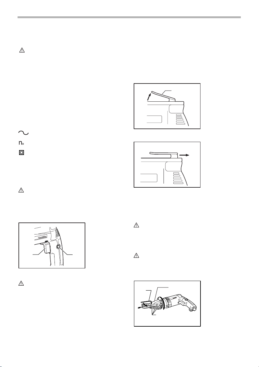
Hook
The hook is convenient for temporary hanging the tool.
When using the hook, pull it out in “A” direction and then
push it in “B” direction to secure in place.
A
004676
1
1. Hook
004677
.......................Class II Construction
.../min....................revolutions or reciprocation per
minute
FUNCTIONAL DESCRIPTION
CAUTION:
• Always be sure that the tool is switched off and
unplugged before adjusting or checking function on
the tool.
Switch action
12
CAUTION:
• Before plugging in the tool, always check to see
that the switch trigger actuates properly and returns
to the “OFF” position when released.
• Switch can be locked in “ON” position for ease of
operator comfort during extended use. Apply caution when locking tool in “ON” position and maintain
firm grasp on tool.
To start the tool, simply pull the switch trigger. Tool speed
is increased by increasing pressure on the switch trigger.
Release the switch trigger to stop.
004668
1. Switch trigger
2. Lock button
B
When not using the hook, return it back to its initial position by following the above procedures in reverse.
ASSEMBLY
CAUTION:
• Always be sure that the tool is switched off and
unplugged before carrying out any work on the tool.
Replacement of blades
CAUTION:
• Never remove the blades with bare hands. Wear
gloves. Otherwise it can cause injury.
Removing cutting head
1
2
3
4
4
007431
1. Hex wrench
2. Loosen
3. Screws
4. Cutting head
Use the hex wrench to loosen the three screws which
secure the cutting head. Pull the cutting head straight out
to remove it with turning it left and right alternately.
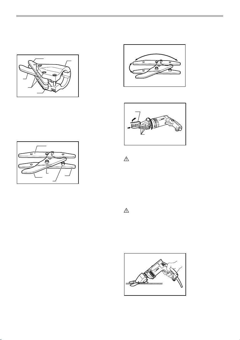
Removing shear blades
1
007432
5
1. Side blade
2. Center blade
3. Screws
4. Side blade
2
5. Cutting head
3
4
Remove the two screws (middle and front) which hold the
cutting head. When removing the middle screw, be careful not to lose the spacer. Then the blades can be
removed easily. When removing the blades, hold the
blades, the spacer and the pivot sleeve so that they do
not fall from the cutting head.
Installing shear blades
1
007433
1. Side blade
2. Center blade
3. Side blade
4. Pivot sleeve
5. Spacer
4
2
3
5
Install the spacer and the pivot sleeve and tighten the
three screws after inserting the center blade, side blades
into the cutting head. In this process, the screw heads
should be protruding 2 - 3 mm (1/16”-1/8”) from the cutting head surface.
If you will tighten the screws excessively, the cutting head
cannot be installed to the tool.
NOTE:
• Side blade edge can be used in four ways by repo-
sitioning them left-to-right and end-to-end as shown
in the figure.
The following describes time and procedure
to change blades.
A) When the two side blades have rounded
about half their width, they can be repositioned left-to-right for new cutting edges.
B) When both edges of each side blade have
rounded about half their width, reposition
them end-to-end for two new cutting
edges.
C) When all edges have worn down, obtain
replacements from Makita authorized or
factory service center.
D) When side blades are worn out, the center
blade should also be replaced.
2
007435
1. Reposition endto-end
2. Reposition leftto-right
1
Installing cutting head
007436
1. Hex wrench
1
2
2. Tighten
3. Screws
3
CAUTION:
• Secure the cutting head firmly. Otherwise it can
rotate during operation and can cause serious
injury.
Insert the cutting head into the tool with turning it left and
right alternately. Then tighten the three screws with the
hex wrench.
OPERATION
CAUTION:
• This tool is intended for cutting fiber cement mate-
rial only, with a thickness of 5/16” or less. Do not
cut other materials or stack-cut. Doing so will damage the tool and void warranty.
• Wear gloves. Otherwise it can cause injury.
Secure the workpiece firmly. Move the tool forward keeping the side blades flush with the workpiece surface.
007434
5
MAINTENANCE
CAUTION:
• Always be sure that the tool is switched off and
unplugged before attempting to perform inspection
or maintenance.
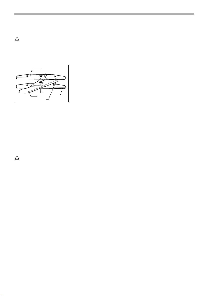
Lubrication
1
4
2
5
Before operation, lubricate the contact point of the center
blade and the side blades. And, also lubricate around the
pivot sleeve and the spacer.
To maintain product SAFETY and RELIABILITY, repairs,
carbon brush inspection and replacement, any other
maintenance or adjustment should be performed by Makita Authorized or Factory Service Centers, always using
Makita replacement parts.
007433
1. Side blade
2. Center blade
3. Side blade
4. Pivot sleeve
5. Spacer
3
ACCESSORIES
CAUTION:
• These accessories or attachments are recom-
mended for use with your Makita tool specified in
this manual. The use of any other accessories or
attachments might present a risk of injury to persons. Only use accessory or attachment for its
stated purpose.
If you need any assistance for more details regarding
these accessories, ask your local Makita Service Center.
• Center blade
• Side blades
• Hex wrench
MAKITA LIMITED ONE YEAR WARRANTY
EN0006-1
Warranty Policy
Every Makita tool is thoroughly inspected and tested
before leaving the factory. It is warranted to be free of
defects from workmanship and materials for the period of
ONE YEAR from the date of original purchase. Should
any trouble develop during this one year period, return
the COMPLETE tool, freight prepaid, to one of Makita’s
Factory or Authorized Service Centers. If inspection
shows the trouble is caused by defective workmanship or
material, Makita will repair (or at our option, replace)
without charge.
This Warranty does not apply where:
• repairs have been made or attempted by others:
• repairs are required because of normal wear and
tear:
• the tool has been abused, misused or improperly
maintained:
• alterations have been made to the tool.
IN NO EVENT SHALL MAKITA BE LIABLE FOR ANY
INDIRECT, INCIDENTAL OR CONSEQUENTIAL DAMAGES FROM THE SALE OR USE OF THE PRODUCT.
THIS DISCLAIMER APPLIES BOTH DURING AND
AFTER THE TERM OF THIS WARRANTY.
MAKITA DISCLAIMS LIABILITY FOR ANY IMPLIED
WARRANTIES, INCLUDING IMPLIED WARRANTIES
OF “MERCHANTABILITY” AND “FITNESS FOR A SPECIFIC PURPOSE,” AFTER THE ONE YEAR TERM OF
THIS WARRANTY.
This Warranty gives you specific legal rights, and you
may also have other rights which vary from state to state.
Some states do not allow the exclusion or limitation of
incidental or consequential damages, so the above limitation or exclusion may not apply to you. Some states do
not allow limitation on how long an implied warranty lasts,
so the above limitation may not apply to you.
6
 Loading...