

Page 1
T
ECHNICAL INFORMATION
Model No.
Description
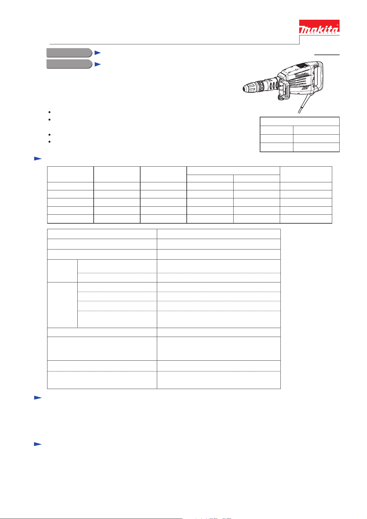
HM1214C
Demolition Hammer
CONCEPT AND MAIN APPLICATIONS
Model HM1214C is a 10kg-class demolition hammer adapted for
SDS-MAX bits.
The main features are as follows:
AVT (Active dynamic vibration absorber)
for reduced vibration during chipping
Suppression of motor speed during no-load
for reduced vibration when idling
In-line tool design optimum for downward vertical applications
High work efficiency
Specification
Dimensions: mm (")
Length (L)
Width (W)
Height (H)
PRODUCT
P 1/ 20
700 (27-1/2)
129 (5-1/8)
265 (10-3/8)
Voltage (V) Cycle (Hz)
110
120
220
230
240
Impacts per min: min-1=ipm
Shank type Adapted for SDS-MAX bits
Shank diameter: mm (")
Vibration
absorption
Electronic
control
Double insulation
Power supply cord: m (ft)
Net weight: kg (lbs)
AVT (Active dynamic
vibration absorber)
Vibration absorbing handle
Variable speed control by dial
Soft start
Constant speed control
Suppression of motor speed
during no-load
Current (A)
15
14
7.8
7.8
7.8
50/60
50/60
50/60
50/60
50/60
Europe, Korea, Cyprus: 4.0 (13.1)
Other countries: 5.0 (16.4)
Continuous Rating (W)
Input Output
1,510
--1,510
1,510
1,510
950 - 1,900
18 (11/16)
Yes
No
Yes
Yes
Yes
Yes
Yes
Brazil: 2.0 (6.6)
11.7 (25.8)
700
700
750
750
750
Max. Output (W)
1,600
1,600
1,800
1,800
1,800
Weight according to
EPTA-Procedure 01/2003: kg (lbs)
12.3 (27.1)
Standard equipment
Side handle (D-shaped) ........... 1
Bit grease .................................. 1
Bull point .................................. 1
Note: The standard equipment for the tool shown above may vary by country.
Plastic carrying ........................ 1
Cleaning cloth .......................... 1
Optional accessories
Bull points
Cold chisels
Scaling chisels
Scaling chisel (for Tile)
Grooving chisel
Clay spade
Bushing tool
Rammer
Grease vessel (containing 30g hammer grease)
Plastic carrying case
Safety goggles
Hammer service kit
Page 2
P 2/ 20
Repair
CAUTION: Remove the hammer bit from the machine and disconnect the Machine from
power source for safety before repair/ maintenance in accordance with the
instruction manual!
[1] NECESSARY REPAIRING TOOLS
[2] LUBRICATIONS
[2] - 1 Tool holder section
Fig. 1A
Code No. Description Use for
1R003 Retaining ring S pliers ST-2N Removing Ring spring 26
Pressing down Slide sleeve for easy removing of Ring spring 43
1R023
1R024
Pipe Ring (for Arbor press)
Press Tool (for Arbor press)
Assembling Helical gear 521R031
Bearing setting pipe 28-20.2
Removing Counter shaft1R045
Gear extractor (large)
Attaching to 1R045, when removing Counter shaft1R346
Center Attachment
Supporting Crank shaft for assembling Helical gear 521R165
Gear extractor (large)
Fitting Fluoride ring 28 on Impact bolt1R214
Taper sleeve
Removing / Assembling Crank shaft1R217
Ring 22
Removing M4 Hex socket head bolts1R228
1/4” Hex Shank bit for M4
Removing M6 Hex socket head bolts1R230
1/4” Hex Shank bit for M6
Removing M8 Hex socket head bolts1R231
1/4” Hex Shank bit for M8
Removing M8 Hex socket head bolts1R246
Round Bar for Arbor 18-100
Removing Retaining ring S-8 from Counter shaft1R291 Retaining ring S & R pliers
Disassembling AVT mechanism1R306
Ring spring removing Jig
Pressing down Flat washer 30 for easy removing Ring spring 261R363 Ring spring removing tool
Removing Ball bearing 6203LLB1R247
Round Bar for Arbor 20-100
Separating Cylinder 40 and Motor housing from Crank housing1R263
Bearing Extractor
Removing Ball bearing 6000DDW from Commutator end of Armature1R269
Bearing Extractor (small)
Removing Ball bearing
1R212 Tip for Retaining Ring Pliers Attaching to 1R003, when removing Ring spring 26
Item No.
Apply Makita grease N.No.2 to the following portions designated with the gray triangle to protect parts
and product from unusual abrasion.
Description Portion to lubricate
Chuck cover
Tool holder section
1
13
14
5
6
8
Release cover
Change ring cover
Tool holder
1 Tool holder cap
Rubber ring 30
Chuck ring
Change ring
Rock ring
Tool retainer
Rip portion
Inside where Tool holder contacts
Inside where 8 Tool retainers contact
Inside which 14 Lock ring accepts
Its inside where Tool holder contacts
The belly portion where Hammer bit contacts
5
6
8
13
14
Page 3
P 3/ 20
Repair
[2] LUBRICATIONS
[2]-2 Hammer section
Apply Makita grease R.No.00 to the following portions designated with the black triangle to protect parts
and product from unusual abrasion.
Apply Makita grease N.No.1 and Makita grease R.No.00 to the following portions designated with the black triangle to
protect parts and product from unusual abrasion.
Fig. 1C
Item No. Description Portion to lubricate
Rubber ring 24
Piston
Connecting
rod
Shoulder sleeve
Impact bolt
Cylinder section
Striker
24
25
35
25 Fluoride ring 28
35 Cylinder 40
24 X ring 21
Out side for smooth moving of Impact bolt in Tool holder
a
b Apply approx. 10g grease for smooth moving of Striker and Piston
a Apply approx. 10g grease for smooth moving of Striker and Impact bolt
b
44
44 Pin 12
Drum portion for smooth moving of Connecting rod
18
Barrel complete
a Inside of Tool holder guide which accepts Tool holder
b Inside of Barrel complete for smooth moving of Weight guide of AVT.
[2]-3 Gear and Crank section
Fig. 1B
Barrel and AVT mechanism
18
a
Tool holder guide
(factory-assembled)
b
Counter weight
Compression spring 58
Cylinder guide
Slide sleeve
Weight guide, covering
Counter weight
35
Gear complete 34-48
Ball bearing 6304LLU
Crank shaft
65 Needle bearing 1613 Needle portion where Counter shaft is accepted
Helical gear 52
55
61
Item No. Description Portion to lubricate
55 Oil seal 20 Lip portion
approx. 50g Makita grease N.No.1
a little of Makita grease R No. 00
a little of Makita grease R No. 00
approx. 60g Makita grease R No. 00
Crank housing complete
61
Counter shaft
65
a
b
a Gear room for smooth engaging of Gears
b Crank room
Gear and Crank section
Fig. 1D
Page 4
P 4/ 20
Repair
[3] DISASSEMBLY/ASSEMBLY
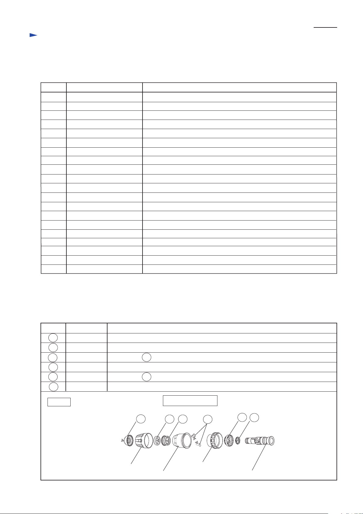
[3]-1. Chuck section
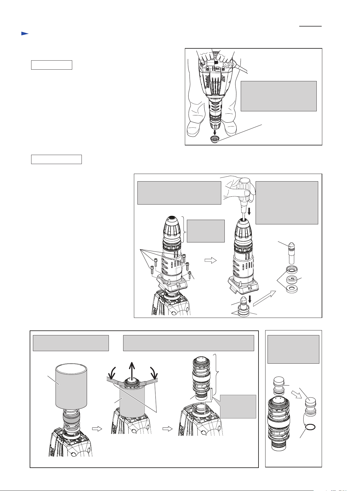
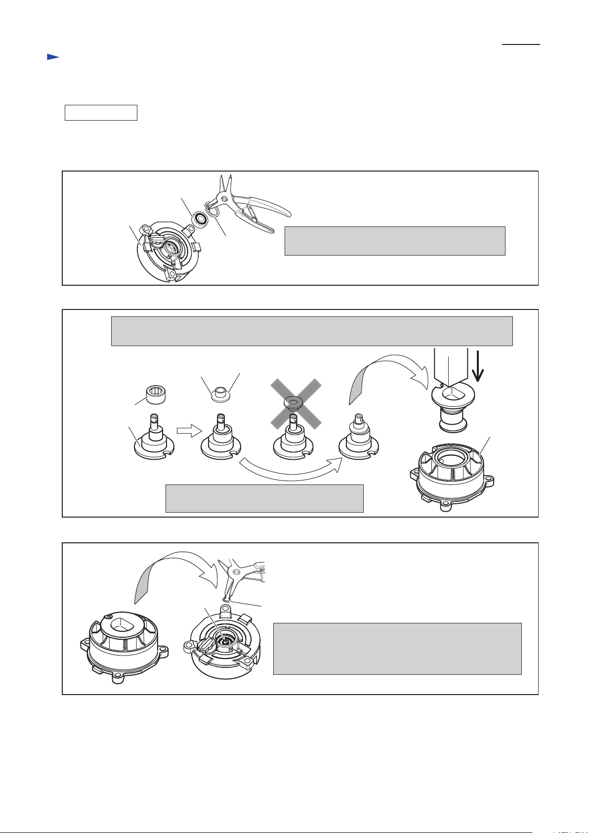
DISASSEMBLING
Controller
cover
Handle section
Tool holder cap
Ring
spring 26
Flat washer 30
Pressing down Flat Washer 30 with
1R363, remove Ring spring 26.
1R363
Socket
Wrench 13
Chuck cover
Release cover
slotted head screwdriver
You can stand the Machine for easy repairing
of these sections.
Remove Tool holder
cap.
Ring spring 26, Flat
washer 30 and Tool
holder come into sight.
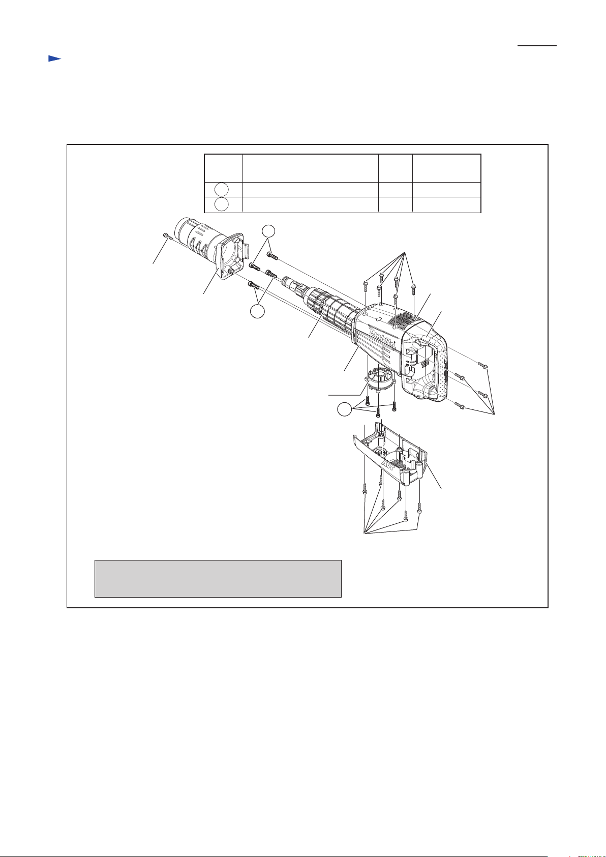
Separating Handle section, remove Controller cover by
disconnecting Controller’s connector from Brush holder
unit. Electrical parts (Switch, Controller, Power supply
cord) can be removed as a unit.
M6x30 Hex
socket head
bolt (4pcs.)
4x18 Tapping
Screw (2pcs.)
Controller
Switch
Remove Handle section and Controller cover so that you can stand the machine for easy repairing of the section except
Motor and Crank section. See Fig. 2.
Chuck section can be disassembled as illustrated in Figs. 3 and 4.
Power supply cord
Fig. 2
Fig. 3
Fig. 4
Flat washer 30
Rubber ring 30
Chuck ring
1R212
The following parts can
be removed.
Tool retainer
Spring guide
Tool retainer
Remove Tool retainer,
pressing down Spring
guide.
Remove Spring guide and
Compression spring 56.
Remove Change
ring cover.
Change ring will
come with it.
Spring guide
Compression
spring 56
Change
ring
Retaining ring
WR-45
Retaining ring
WR-45
Change
ring cover
Change
ring cover
Change
ring
Remove Retaining ring WR-45.
Change ring can be separated
from Change ring cover.
Page 5
P 5/ 20
Repair
[3] DISASSEMBLY/ASSEMBLY
[3]-1. Chuck section
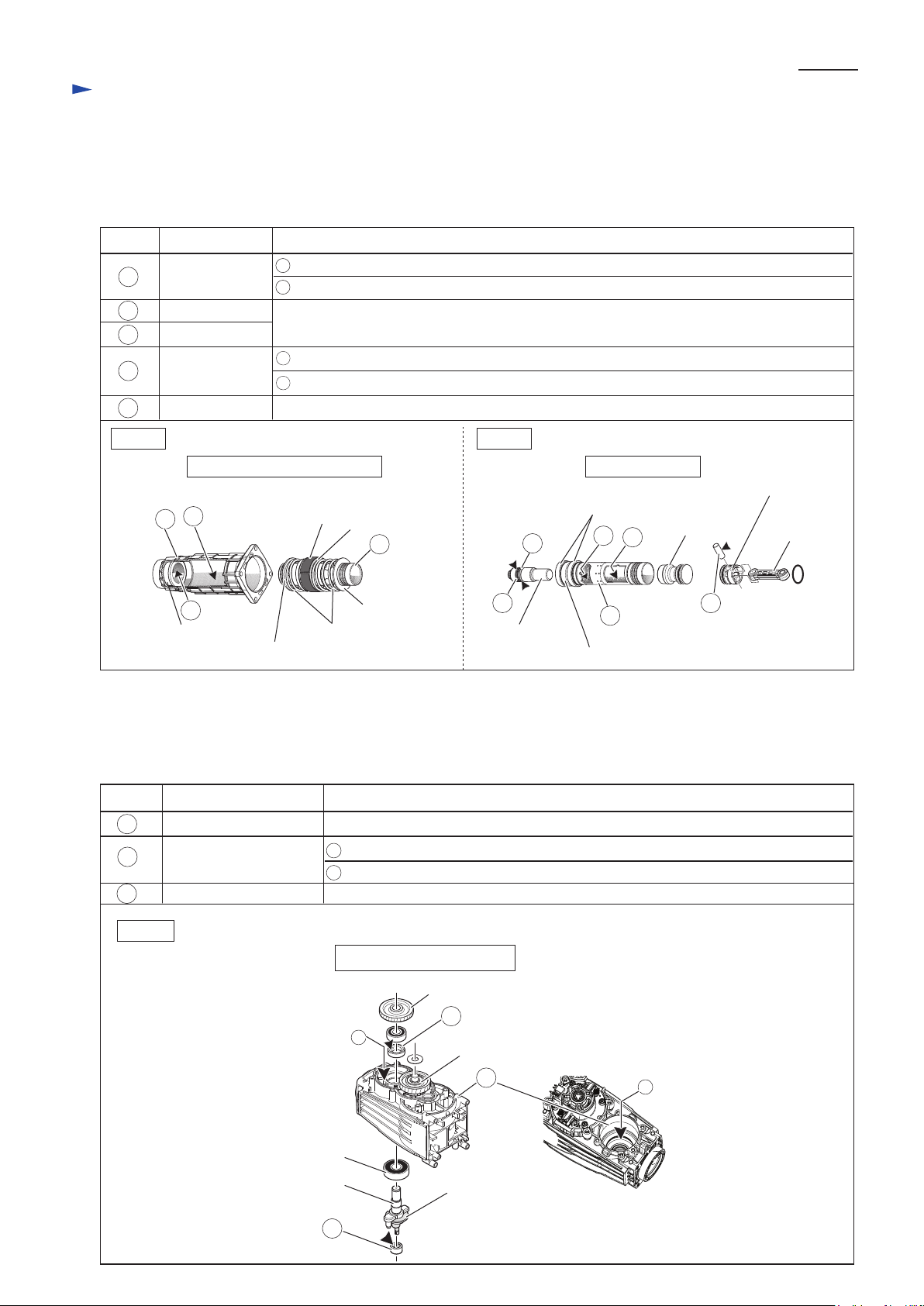
[3]-2. Barrel section
DISASSEMBLING
ASSEMBLING
Fig. 5
Fig. 6
(1) Do the reverse step of Disassembly. Refer to Figs. 4and 3.
However, assemble Handle section before mounting
Tool holder cap.
(2) Assemble Tool holder cap as illustrated in Fig.5.
Put Tool holder cap on ground,
and push Tool holder to
Tool holder cap while making
use of the machine weight.
Tool holder cap
(1) Remove Handle section and Controller
cover to hold the machine upright.
(Fig. 2)
(2) Separate Barrel section from Crank
housing complete, and remove Impact
bolt from Barrel section. (Fig. 6)
(3) Disassemble Cylinder and Striker as
illustrated in Figs. 7 and 8.
M8x30 Hex
socket head
bolt (4pcs.)
No need to
disassemble
Chuck section.
Push the removed Barrel
section with screwdriver
inserted from Tool holder
cap. Impact bolt can be
removed from Barrel
section.
Separate Barrel, Barrel cover and
Chuck section from Crank housing
complete as illustrated below.
M6x30 H.S
head bolt
with GM
Impact bolt
Rubber ring 24
Impact bolt
Shoulder
sleeve
Rubber
ring 24
Shoulder sleeve
1R023
Note: Even after removing Cylinder 40, do not lay Crank housing
complete,
Pin 6 (a component of AVT) can easily fall out of Crank
housing complete.
1R023
Striker
Take out Striker from
Cylinder 40, and
Remove O ring 31.5
from Striker.
O ring 31.5
1R263
Cylinder 40
Pull off Pin 6
after removing
Cylinder.
Put 1R023 onto Crank housing
as illustrated below.
Remove Cylinder 40 and Pin 6, as illustrated below.
The component parts of AVT come with Cylinder 40.
Fig. 7
Fig. 8
Components
of AVT
Page 6
P 6/ 20
Repair
[3] DISASSEMBLY/ASSEMBLY
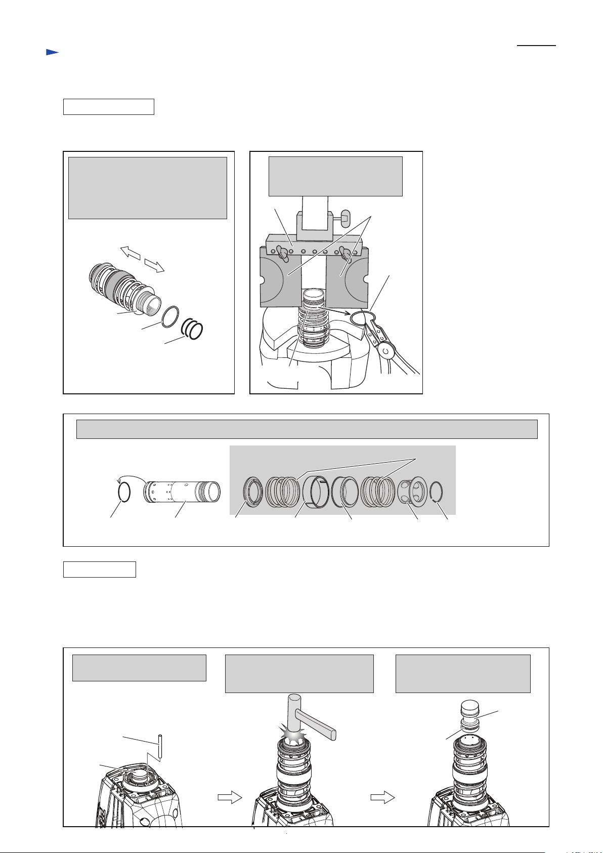
[3]-2. Barrel section (cont.)
DISASSEMBLING
ASSEMBLING
Crank housing side
Ring 45
O ring 36 (3pcs.)
Slide sleeve
Compression spring 58
Tool holder side
Remove O ring 36 and Ring 45 from
Crank housing side of Cylinder 40 as
illustrated below.
Ring spring 43 still remains on the
Cylinder as a stopper for Slide sleeve.
1R024
or
1R356
Fig. 9 Fig. 10
Fig. 11
O Ring 41
After removing Ring spring 43, the component parts of AVT are removed from Cylinder 40 as illustrated below.
Cylinder 40 Cylinder
guide
Weight
guide
Counter
weight
1R306
Pressing down Slide sleeve as
illustrated below, remove Ring
spring 43.
Ring
spring 43
Slide
sleeve
Ring spring 43
Component parts of AVT
Slide sleeve
(4) The components of AVT can be removed from Cylinder 40 (Figs. 9
(1) Assemble O ring 41 to Cylinder 40. And assemble the component parts of AVT. (Fig. 11)
(2) Secure the component parts of AVT with Ring spring 43. (Fig. 10)
(3) Assemble Ring 45 and 3 pcs. of O ring 36 to Cylinder 40. (Fig. 9) The assembling of Cylinder section is finished.
And mount it to Crank housing as illustrated in Fig. 12.
Pin 6
Piston
Do not forget to assemble Pin 6
for AVT mechanism.
Aligning Cylinder hole to Piston,
insert Cylinder into Crank housing
complete by striking.
O ring 31.5
Facing O Ring 31.5 assembled
side to Crank housing complete,
insert Striker into Cylinder 40.
Striker
Fig. 12
Page 7

P 7/ 20
Repair
[3] DISASSEMBLY/ASSEMBLY
[3]-2. Barrel Section (cont.)
ASSEMBLING
X ring 21
O ring 23
Fluoride ring 28
(the worn one)
Impact bolt
In the following cases all the Rings on
Impact bolt have to be replaced.
* When carbon brush is replaced.
* O ring 23 (orange) shows hrough
the worn Fluoride ring 28.
Taper sleeve
(No.1R214)
Correction
Insert Impact bolt from
the HR5001C side of
the Taper sleeve. And
keep it aprox. 60 sec. in
the Taper sleeve.
Impact bolt
Assemble of Rings to Impact bolt
Before Correction:
Rings' edges are protruding from the top edge
of the groove on Impact bolt.
groove on Impact bolt
Fluoride ring 28
X ring 21
O ring 23
After Correction:
Rings' edges are positioned under the top
edge of the groove on Impact bolt.
Corrected
Fig. 13
(4) If the wearing away on Fluoride ring 28 is recognized in the step of Fig. 6, all the Rings on Impact bolt have to be
replaced as illustrated in Fig. 13.
1. Insert Impact bolt into
Tool holder mounted
in Barrel complete
2. Put Shoulder sleeves and
Rubber ring 24 onto the
Cylinder 40.
Shoulder sleeve
Cylinder 40 fits to this Concave.
3. Assemble Barrel complete
to Cylinder 40 while fitting
Tool holder to Shoulder
sleeve’s concave.
Tool holder in Barrel complete,
fits to this Concave.
The tail of Impact bolt is
passed through these holes.
Rubber ring 24
Shoulder sleeve
Cylinder 40
Fig. 14
(4) Assemble Barrel complete to Cylinder 40 as illustrated in Fig. 14.
Impact bolt
Barrel
complete
(5) Secure the Barrel complete with four M8x30 Hex socket head bolts and one M6x30 Hex socket head bolt
together with Barrel cover. Refer to the left illustration in Fig. 6.
Tool holder
Cylinder 40
Page 8

P 8/ 20
Repair
[3] DISASSEMBLY/ASSEMBLY
[3]-3. Tool holder section
DISASSEMBLING
ASSEMBLING
(1) Disassemble Chuck section as illustrated in Figs. 3 and 4.
(2) Disassemble Tool holder as illustrated in Fig. 15.
M8x30 Hex
socket head
bolt
Separate Barrel section from Crank housing complete.
And pull off Barrel section from Barrel cover.
Removing Ring spring 35, disassemble Tool holder
by striking it with plastic hammer.
M8x30 Hex
socket head
bolt
Barrel cover
Ring spring 35
M6x30 H.
s head bolt
with GM
Fig. 15
Tool holder
O ring 35.5
Barrel complete has to be assembled so that the notch is located on the opposite side of M6 bolt hole. (Fig. 16)
Rubber ring 39
Flat washer 39
Fig. 16
Hole for M6 Bolt bored on
Crank housing complete
Crank housing complete
Barrel complete
Notch of Barrel
complete
Page 9
P 9/ 20
Repair
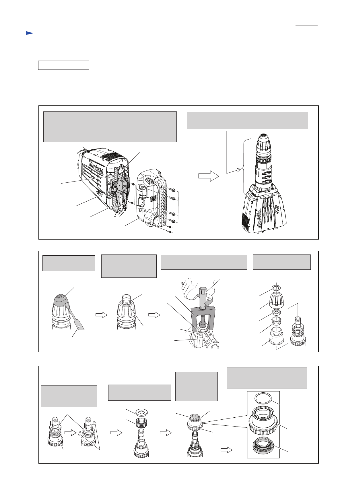
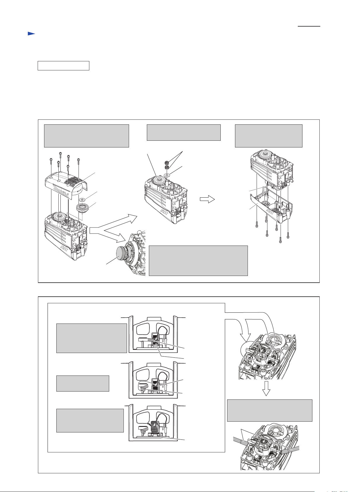
[3] DISASSEMBLY/ASSEMBLY
[3]-4. Bearing box section, Piston, Crank section
DISASSEMBLING
(1) Remove Handle section and Controller cover to hold the machine upright. (Fig. 2)
(2) Separate Barrel section from Crank housing complete (the left illustration in Fig. 6)
(3) Disassemble Cylinder section (Fig. 7)
(4) For repairing Piston & Crank section, Motor section has to be separated from Crank housing complete.
Separate Motor housing from Crank housing complete in order of Figs. 17 and 18.
M6x30 Hex socket
head bolt (6pcs.)
M6x30 Hex socket
head bolt (6pcs.)
Gear cover
Disassemble Gear cover, and then,
remove Flat washer 14 and Gear
complete 34-48.
Disassemble Rear cover.
So, Motor housing comes
into your sight.
And then, remove two Needle
gauges and Flat washer 14.
Rear cover
Helical gear 52
Motor
housing
Flat washer 14
Gear
complete 34-48
Needle gauge
1412 (2pcs.)
Flat washer 14
Turn Helical gear 52 until Piston comes
out from Crank housing complete.
O rings on Piston can be replaced in this
step.
Remove Motor housing by levering
it up with 2 pcs. of 1R263 as
illustrated below.
Carbon brush is pressed with
Spiral spring to maintain its
contact with Armature's
commutator.
Carbon brush
Disconnection of the Contact of Carbon brush with Commutator
Spiral spring
Carbon brush
Carbon brush
Spiral spring
Detach Spiral spring
from Carbon brush.
By pulling Carbon brush,
disconnect the contact with
Armature's commutator.
Fig. 17
Fig. 18
1R263
Piston
Page 10
P 10/ 20
Repair
[3] DISASSEMBLY/ASSEMBLY
[3]-4. Bearing box section, Crank housing section (cont.)
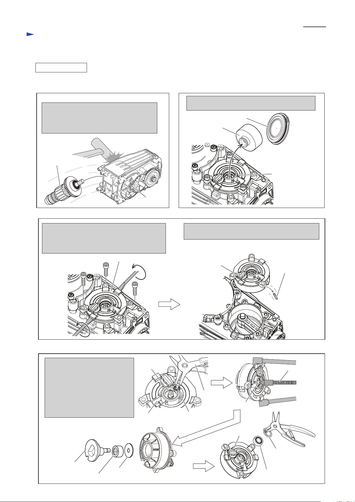
DISASSEMBLING
Fig. 19
Even after removing Motor housing, Armature
still remains in Crank housing complete.
Disassemble Armature by striking the edge of
Crank housing complete as illustrated below.
Fig. 20
Fig. 21
Fig. 22
Armature
(5) Disassemble Bearing box section in order of Figs. 19 to 24.
M6x25 Hex socket
head bolt (3pcs.)
After unscrewing M6x25 Hex Socket head bolts,
remove Bearing box by twisting two slotted head
screwdrivers inserted between Crank housing
complete and Bearing box complete.
Remove Retaining ring S-8, and
push out Counter shaft with 1R045.
Shoulder washer 8 and Needle
bearing 1613 can be removed from
Bearing box complete together
with Counter shaft.
Remove Retaining ring R-25, Ball
bearing 608ZZ and Grease cap.
Bearing box
complete
Filter case
Filter case cover
Pull off Filter case from Bearing box after removing
Filter case cover.
Bearing box complete
Bearing box
complete
Bearing box
complete
Counter
shaft
Counter shaft
Counter shaft
1R291
Retaining ring S-8
Shoulder
washer 8
Remove Pin 8 that functions for AVT in combination
with Pin 6. Pay attention not to lose Pin 8.
Pin 8
Pin 8
Grease cap
1R045
Needle bearing 1613
Ball bearing 608ZZ
Retaining
ring R-25
Page 11

Piston
Connecting rod
P 11/ 20
Repair
[3] DISASSEMBLY/ASSEMBLY
[3]-4. Bearing box section, Crank housing section
DISASSEMBLING
Fig. 23 Fig. 24
Filter case cover and Filter case (Re: Fig. 20)
can be disassembled.
O ring 72 and O ring 14 can be removed from
Bearing box complete and Grease cap
Filter case
Filter
Filter case cover
O ring 18
O ring 45
O ring 71
Grease cap
Bearing box complete
O ring 14
(6) In the step of Fig. 21 (after removing Bearing box complete), Piston can be disassembled from Crank housing
complete as illustrated in Fig. 25.
(7) Crank shaft section can be disassembled as illustrated in Fig. 26.
Align Piston, Connecting rod and Crank shaft
on their center line by turning Crank shaft, .
Piston can be removed from Crank housing
complete together with Connecting rod.
Piston
Connecting rod
To stabilize Crank housing during
disassembly, put it onto 1R217.
And apply 1R246 to Crank shaft
and press down Crank shaft.
Apply 1R247 to Ball bearing
6203LLU from Bearing box
complete side, and press down
Ball bearing 6203LLU.
Helical gear 52 and Crank
shaft section are disassembled
as illustrated below.
Crank shaft
Crank Shaft
1R246
Crank housing
complete
Fig. 25
Fig. 26
1R247
Helical gear 52
Crank Shaft
Ball bearing
6304LLU
Ball bearing
6203LLB
Ball bearing 6203LLB
Oil seal 20
1R217
Crank housing complete
Page 12

P 12/ 20
Repair
[3] DISASSEMBLY/ASSEMBLY
[3]-4. Bearing box section, Crank housing section
ASSEMBLING
Lip portion
of Oil seal 20
Facing the lip portion to the side of box for Ball bearing
6304LLU (large Bearing), assemble Oil seal 20 by
pressing down until they stop.
Side of box for Ball bearing
6304LLU (large bearing)
Assemble Ball bearing 6304LLU
to Crank shaft as illustrated below.
Oil seal 20
(1) Assemble Crank shaft with Ball bearing 6304LLU to Crank housing complete as illustrated in Figs. 27 and 28.
Crank shaft
Crank shaft
Ball bearing
6304LLU
1R217
1R217
Setting Crank housing complete on 1R217,
assemble the Crank shaft with arbor press as
illustrated below. And then turn Crank housing
complete.
Put it onto 1R165 while aligning the assembled
Crank shaft to the 1R165.
Assemble Ball bearing 6203LLB. And then, assemble
Helical gear 52 as illustrated below.
Crank housing
complete
1R165
Crank shaft
Helical gear 52
Helical Gear 52 has to be assembled so that Crank shaft protrudes
approx. by 3 - 4 mm from the Helical gear 52.
The protruding portion of Crank shaft is accepted by the boss of
Gear housing.
Crank shaft
1R031
Helical
gear 52
Ball bearing
6203LLB
Crank shaft
3 - 4 mm
1R031
Note in Assembly
1R031
Gear
housing
Boss
Fig. 27
Fig. 28
Page 13
P 13/ 20
R
epair
[3] DISASSEMBLY/ASSEMBLY
[3]-4. Bearing box section, Crank housing section (cont.)
ASSEMBLING
(2) Assemble Piston together with Connecting rod to Crank shaft. Refer to the right illustration in Fig. 25.
(3) Assemble Bearing box complete as illustrated in Figs. 29 to 31.
Insert Needle bearing 1613 and Shoulder washer 8 over Counter shaft. Assemble Counter shaft
to Bearing box complete by pressing down with arbor press.
Assemble Ball bearing 608ZZ to Bearing box.
And secure the Ball bearing with Retaining ring R-25.
Needle
bearing 1613
Brim portion
Shoulder washer 8
Counter shaft
When assembling Shoulder washer 8,
face the brim portion to Needle bearing side.
Turning Bearing box complete, mount Retaining ring S-8 to
Counter shaft.
The assembled Bearing box complete is ready to be mounted
to Crank housing complete in the next step.
Retaining
ring R-25
Ball bearing 608ZZ
Bearing box
complete
Counter shaft
Retaining
ring S-8
Fig. 29
Fig. 30
Fig. 31
Bearing box
Complete
Page 14

P 14/ 20
Repair
[3] DISASSEMBLY/ASSEMBLY
[3]-4. Bearing box section, Crank housing section (cont.)
ASSEMBLING
Fit the Notch of Counter shaft to the pin portion of Crank shaft by turning Counter shaft with Wrench 7.
(Unless the notch of Counter shaft fits to the pin portion of Crank shaft, approx. 5mm gap arises between
Bearing box complete and Crank housing complete.)
Pin portion of Crank shaft
When assembling Gear complete 34-48 and Needle gauge 112,
do not forget to mount two Flat washers as illustrated below.
The notch of Counter shaft fits to the pin portion
of Crank shaft. Bearing box complete can be exactly
mounted to Crank housing complete without any gap.
The notch of Counter shaft does
not fit to the pin portion of Crank
shaft in this step.
Notch of Counter shaft
Gap between Bearing box
complete and Crank housing
complete
Bearing box
complete
Counter shaft
Condition under Bearing box complete
Wrench 7
Crank housing
complete
Wrench 7
Fig. 32
Fig. 33
Needle gauge 1412
(2pcs.)
Flat washer 14
(6) As for the further steps, do the reverse step of Disassembly.
Flat washer 14
Gear complete 34-48
4) Mount Bearing box complete to Crank housing complete as illustrated in Figs. 32.
5) Mount Gear complete 34-48 to Crank housing complete as illustrated in Figs. 33.
Page 15

1R023
1R024
P 15/ 20
Repair
[3] DISASSEMBLY/ASSEMBLY
[3]-5. Motor section
DISASSEMBLING
ASSEMBLING
(1) Remove Rear cover (with “AVT” mark) from Crank housing complete (Re: the right illustration in Fig. 17)
(2) Disconnecting Carbon brush from Armature’s commutator, separate Motor housing from Crank housing complete. (Fig. 18)
(3) Disassemble Armature, by striking the edge of Crank housing complete. (Fig. 19)
(4) Ball bearings on Armature can be removed as illustrated in Fig. 34.
Ball bearing
6000DDW
Remove Ball bearing 6000DDW,
and Insulation washer from the
Commutator end,
Insulation
washer
Ball bearing 6302LLU
Sealing screw
Sealing screw and Ball bearing 6302LLU
are removed in one process by pressing
down with arbor press.
1R023
Do the reverse step of Disassembly.
1R022
1R024
1R269
Fig. 34
Page 16

P 16/ 20
Repair
[3] DISASSEMBLY/ASSEMBLY
[3]-6. Electrical parts in Handle section
DISASSEMBLING
(1) Remove Handle section from Crank housing and Motor housing. The following electrical Parts can be replaced as
illustrated in Fig. 2.
* Switch
* Controller
* Power supply cord
(2) Separate Handle cover from Handle. The parts for switching mechanism are disassembled as illustrated in Fig. 35.
ASSEMBLING
Disassemble Switch lever from Side lever by unscrewing
4x18 Tapping screw. And Remove Slide lever from Handle.
Pay attention not to lose Leaf spring in this step.
Switch lever
Switch
lever
Slide lever
Unscrew 4x18 Tapping screw,
and remove Handle cover.
Leaf
spring
Handle cover
Handle
4x18 Tapping screw
4x18 Tapping screw
4x18 Tapping screw
Fig. 35
(1) When replacing Switch in the step of Fig. 2, do not forget to assemble Rubber pin 4 to the illustrated position in Fig. 36.
Switch
Tumbler of Switch is controlled by the pronged portion of
Switch lever that is joined to Slide lever with 4x18 Tapping screw.
Fitting the Prong of Switch lever to Tumbler of Switch, assemble
Handle section to Crank housing complete.
Rubber Pin 4
(green color)
Fig. 36
Fig. 37
Tumbler of
Switch
Prong of
Switch Lever
(2) Mount Leaf spring to Slide lever, and assemble Slide lever to Handle. Fasten Switch lever to the Slide lever with
4x18 Tapping screw. And mount Handle cover to Handle. Refer to the illustrations in Fig. 35.
(3) Assemble the Handle section to Crank housing as illustrated in Fig. 37.
Handle section
Slide Lever
Page 17
P 17/ 20
Repair
[3] DISASSEMBLY/ASSEMBLY
[3]-7. Fastening torque
19
M6x30 Hex socket
head bolt (1 pc.)
<Note in Assembling>
Applying ThreeBond 1342 or Loctite 242 to their thread,
tighten Hex socket head bolts illustrated above.
Barrel complete
Barrel cover
Gear cover
Handle
Rear cover
Bearing box complete
Crank housing complete
M6x30 Hex socket
head bolt (6pcs.)
M6x30 Hex socket
head bolt (6pcs.)
M6x30 Hex socket
head bolt (4pcs.)
72
19
Position
No.
Fastening
Torque
Used
Q’ty
Size of Hex Socket
Head Bolt
19 4 30 - 40 N.mM8 x 35
72 3 13 - 16 N.m
M6 x 25
Fasten the Bolts and Screws to the fastening torque listed in Fig. 38.
Fig. 38
Page 18

P 18/ 20
Repair
[4] MAINTENANCE PROGRAM
20
22
Flat washer 39
Flat washer 30
Chuck cover
Ring spring 26
Tool holder
Impact bolt
Cylinder 40
1
24
25
26
29
Shoulder
sleeve
32
Striker
Piston
45
47
When replacing carbon brush, it is recommended to replace the following parts at the same time for longer service life
of the machine. Refer to Fig. 39.
Removing old grease, apply the new grease to the portions in Figs. 1A to 1D of the clause of [2] LUBRICATIONS.
Fig. 39
Item No. Item No.Descriptions Descriptions
1
20
22
24
25
Tool Holder Cap
Rubber Ring 39
O Ring 35.5 on Tool holder
X Ring 21 on Impact bolt
Fluoride Ring 28 on Impact bolt
26
29
32
45
47
O Ring 23 on Impact bolt
Rubber Ring 24
O Ring 31.5 on Striker
O Ring 31.5 on Piston
O Ring 35 on Piston
Page 19

Circuit diagram
P 19/ 20
Color index of lead wires' sheath
Blue
Brown
3 1
T2
T1
Controller
Fig. D-1
This Lead wire is white for
some countries.
This Lead wire is black for
some countries.
This Lead wire is white for
some countries.
This Lead wire is black for
some countries.
Switch
Terminal Block
built in Controller
Page 20
Brim side
Brim of Brush
Holder Unit
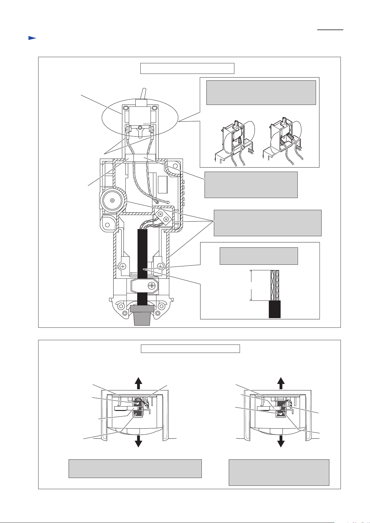
Wiring diagram
wiring on Controller Cover
P 20/ 20
Do not protrude Terminals from the edge
of Controller cover when connecting them
to Switch.
Controller
Cover
Sponge
Pay attention not to pinch the Lead wires
with the edge of Controller or Controller
cover (designated with hatching).
Put Controller’s Lead wires for
connecting to Switch into the slit of
Sponge.
Switch
Terminal
approx. 30mm
Cut the Power supply cord as
illustrated below.
Fig. D-2
Fig. D-3
Correct Wrong
Correct
Wiring of Carbon Brush’s Pig Tail
Wrong
Pig tail’s Root on the brim side of Spiral spring
does not pinch Pig tail by mistake when assembling.
Pig Tail’s Root on the Rear cover side
Spiral spring easily pinches Pig tail by
mistake when assembling.
Brim of Brush
holder unit
Rear Cover Side
Brim side
Rear Cover Side
Spiral Spring, correctly
pressing Carbon Brush
Spiral spring,
pinching Pig tail
Pig Tails
Root
Pig Tail
Pig Tail’s
Root
Carbon
Brush
Carbon
Brush
Pig Tail
 Loading...