

Page 1
T
ECHNICAL INFORMATION
Models No.
HM0871C, HM0870C
PRODUCT
P 1/ 17
Description
Demolition Hammers
CONCEPT AND MAIN APPLICATIONS
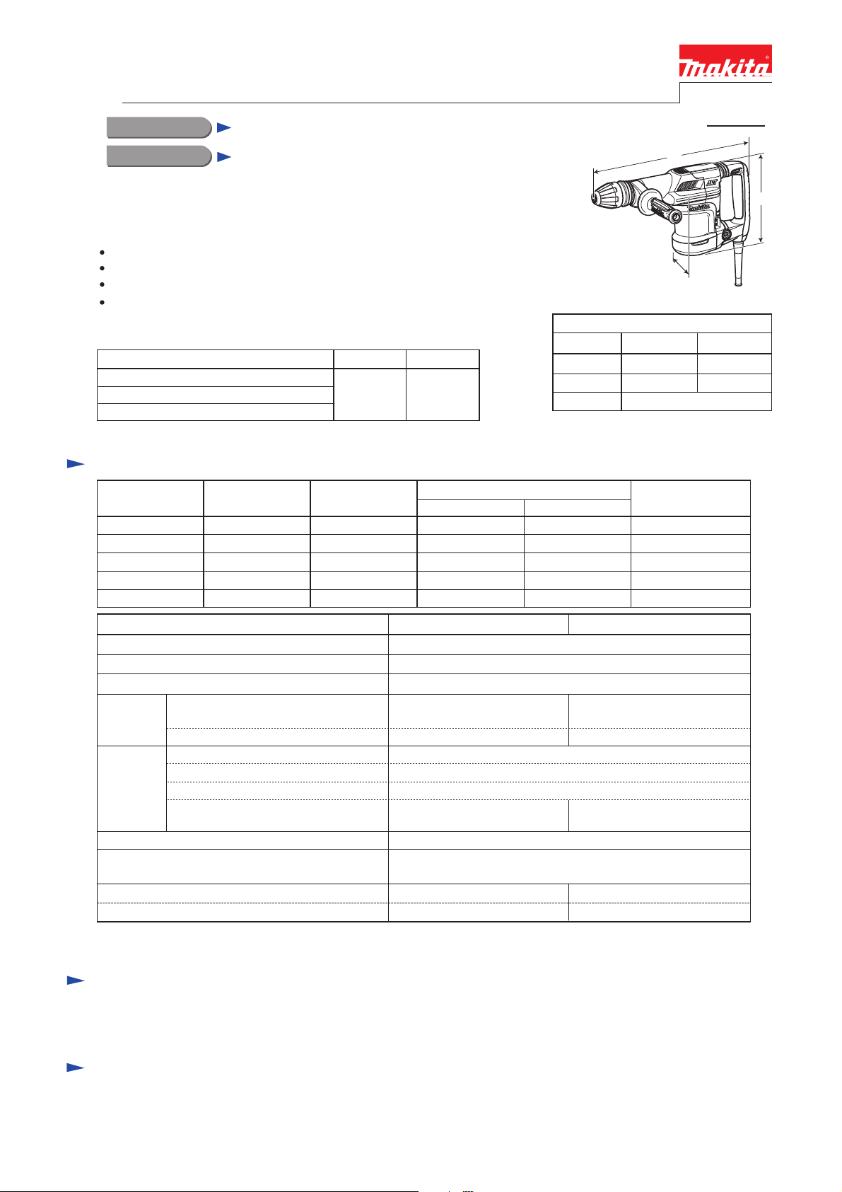
Models HM0871C and HM0870C are 5kg-class demolition hammers
adapted for SDS-MAX bits, and developed from HM0860C, featuring:
Same high work efficiency as HM0860C
Higher durability achieved by using ball bearing for crank section
AVT* for reduced vibration during chipping (HM0871C only)
Suppression of motor speed during no-load for reduced vibration
when idling
Listed below are the specification differences between the two models.
Model No.
AVT*
Vibration absorbing handle
Suppression of motor speed during no-load
*Anti-Vibration Technology using Active dynamic vibration absorber
Yes No
Specification
Voltage (V) Cycle (Hz)
110
120
220
230
240
Current (A)
12
10
5.8
5.8
5.8
50/60
50/60
50/60
50/60
50/60
HM0870CHM0871C
[The image above is HM0871C.]
Model No.
Length (L)
Width (W)
Height (H)
Continuous Rating (W)
Input Output
1,100
---
1,100
1,100
1,100
450
450
500
500
500
L
H
W
Dimensions: mm (")
HM0870CHM0871C
466 (18-3/8) 449 (17-3/4)
116 (4-9/16) 109 (4-1/4)
230 (9)
Max. Output (W)
1,200
1,200
1,200
1,200
1,200
Model No.
Impacts per min: min-1= ipm
Shank type Adapted for SDS-MAX bits
Shank diameter: mm (")
Vibration
absorption
Electronic
control
Double insulation
Power supply cord: m (ft)
Net weight*1: kg (lbs)
Net weight*2: kg (lbs)
*1 Weight according to EPTA-Procedure 01/2003, with bar-shaped Side handle.
*2 Weight according to EPTA-Procedure 01/2003, with D-shaped Side handle.
AVT (Anti-Vibration Technology using
Active dynamic vibration absorber)
Vibration absorbing handle
Variable speed control by dial
Soft start
Constant speed control
Suppression of motor speed
during no-load
Yes No
Yes No
Yes No
Europe, Hong Kong, Korea: 4.0 (13.1);
Brazil: 2.0 (6.6); Other countries: 5.0 (16.4)
5.6 (12.4) 5.1 (11.1)
5.8 (12.8) 5.3 (11.6)
1,100 - 2,650
18 (11/16)
Yes
Yes
Yes
Yes
Standard equipment
Side handle (Bar- or D-shaped) ........... 1
Bit grease .............................................. 1
Note: The standard equipment for the tool shown above may vary by country.
Plastic carrying case ........................ 1
Cleaning cloth .................................. 1
HM0870CHM0871C
Optional accessories
Bull points
Cold chisels
Scaling chisels
Scaling chisel (for Tile)
Grooving chisel
Clay spade
Bushing tool
Rammer
Shank (for Bushing tool and Rammer)
Grease vessel (containing 30g hammer grease)
Side handle (Bar-shaped/ D-shaped)
Safety goggles
Hammer service kit
Page 2
P 2/ 17
Repair
[1] NECESSARY REPAIRING TOOLS
[2] LUBRICATIONS
Fig. 1
Code No.
1R003 Retaining ring S pliers ST-2N
1R212 Tip for Retaining ring pliers
1R005 Retaining ring R pliers RT-2N
1R089 Bearing extractor
1R023 When it is difficult to remove Armature from Crank housing complete.
When it is difficult to remove Ball bearing 6203LLU.
Pipe ring ( for Arbor press)
1R132 Nose 15-20 Attachment for 1R089 to remove Ball bearing 6203LLU
1R139 Drill chuck extractor
M8x40 Hex socket head bolt
Flat washer 8
Removing Crank shaft
Attachment for 1R003 to remove Ring springs
1R214 Taper sleeve Fitting Fluoride ring on Impact bolt
1R229 1/4” Hex shank bit for M5
Unscrewing/ screwing M5 size Hex socket head bolt
1R230 1/4” Hex shank bit for M6
Unscrewing/ screwing M6 size Hex socket head bolt
1R239 Round bar for Arbor 10-100 When it is difficult to remove Armature from Crank housing complete.
1R269 Bearing extractor Removing Ball bearing 608DDW from Armature’s commutator end
1R288 Screwdriver magnetizer
Magnetizing screwdriver when removing Steel balls
1R291 Retaining ring S and R pliers
Removing Ring spring 34 when disassembling Barrel section
1R306 Ring spring removing jig When it is difficult to remove Armature from Crank housing complete.
1R363 Ring spring removing tool
Removing Ring spring 25
Removing Ring springs
Removing Retaining ring (INT) round R-42
Description Use for
Item No.
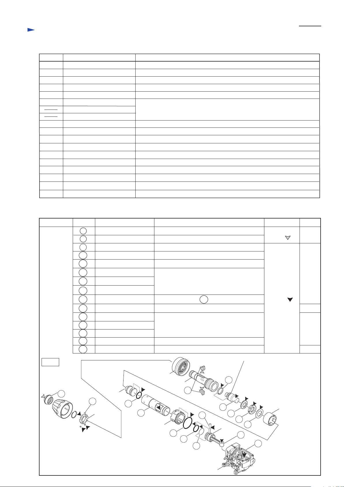
Apply the following lubricants to the portions to protect the parts and product from unusual abrasion.
Description Portion to lubricate Lubricant Amount
a little
a little
a little
1 Tool holder cap
7
7
Tool retainer
Steel ball 4.8 (4pcs.)
Lip portion
Belly portion where Hammer bit contacts
Whole portion
1
Lock ring
Striker
Change ring
Tool holder
16
16
Makita grease
N.No.2
Makita grease
R.No.00
19
21
22
23
27
31
Cylinder guide
Guide ring
O ring 23 between Fluoride ring
28 and Impact bolt
Note: Do not apply any grease
to O ring 23 attached to
Fluoride ring 28.
32
38
50
Piston
Pin of Crank shaft
51
53
58
19
21
22
23
27
31
32
38
49
51
53
58
Fluoride ring 28
Impact bolt
Ring 20
Rubber ring 20
Flat washer 23
O ring 24
Cylinder 32
O ring 46
Pin 8
O ring 26
Connecting rod
Crank housing complete
The surface where Tool holder contacts
Cylindrical portion of Striker side
Whole portion
The surface where 32 Cylinder contacts.
Inside between Striker and Piston.
Whole portion
The hole in which Crank shaft’s pin is inserted
Crank room
49
7g
20g
CAUTION: Repair the machine in accordance with “Instruction manual” or “Safety instructions”.
Page 3
DISASSEMBLING
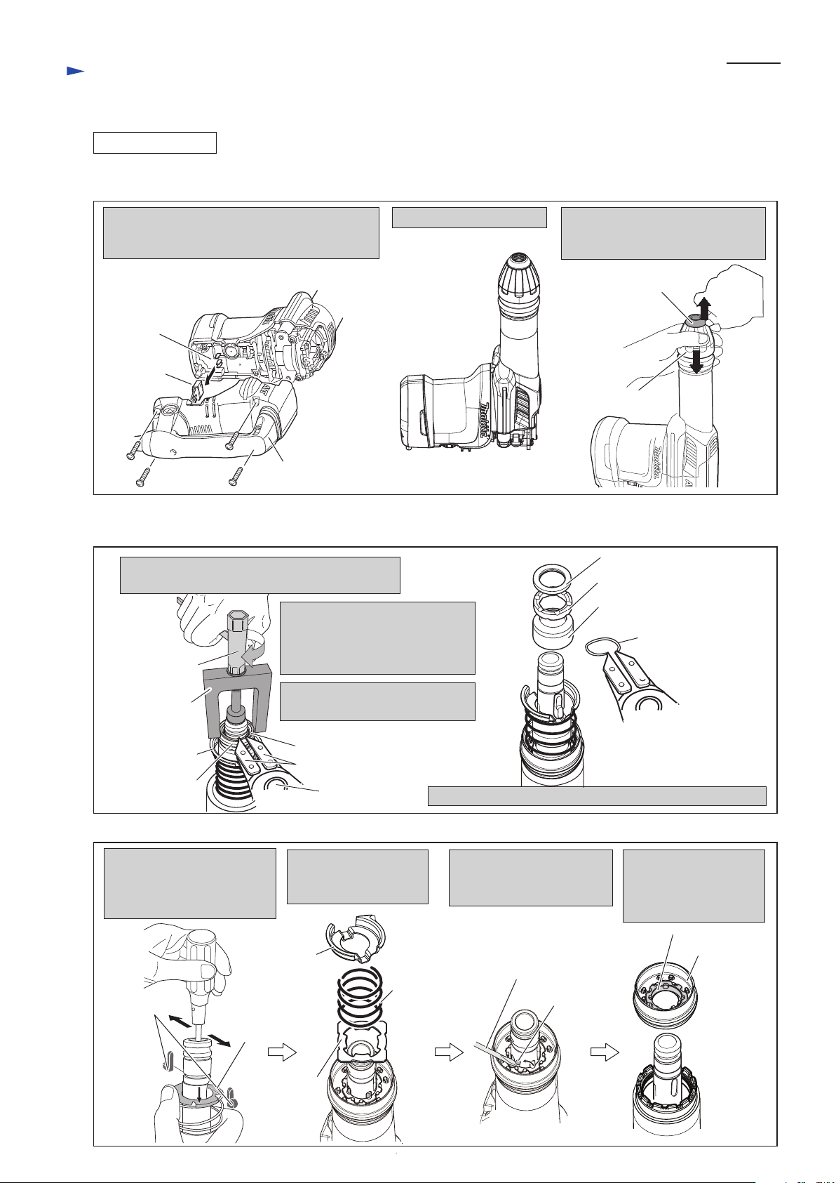
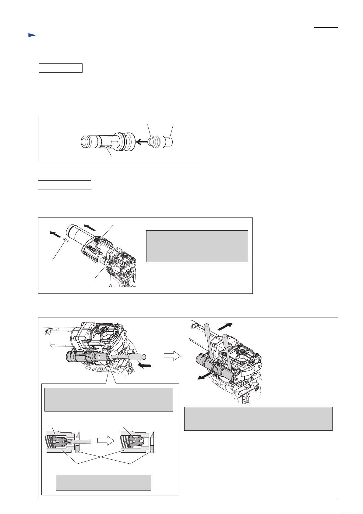
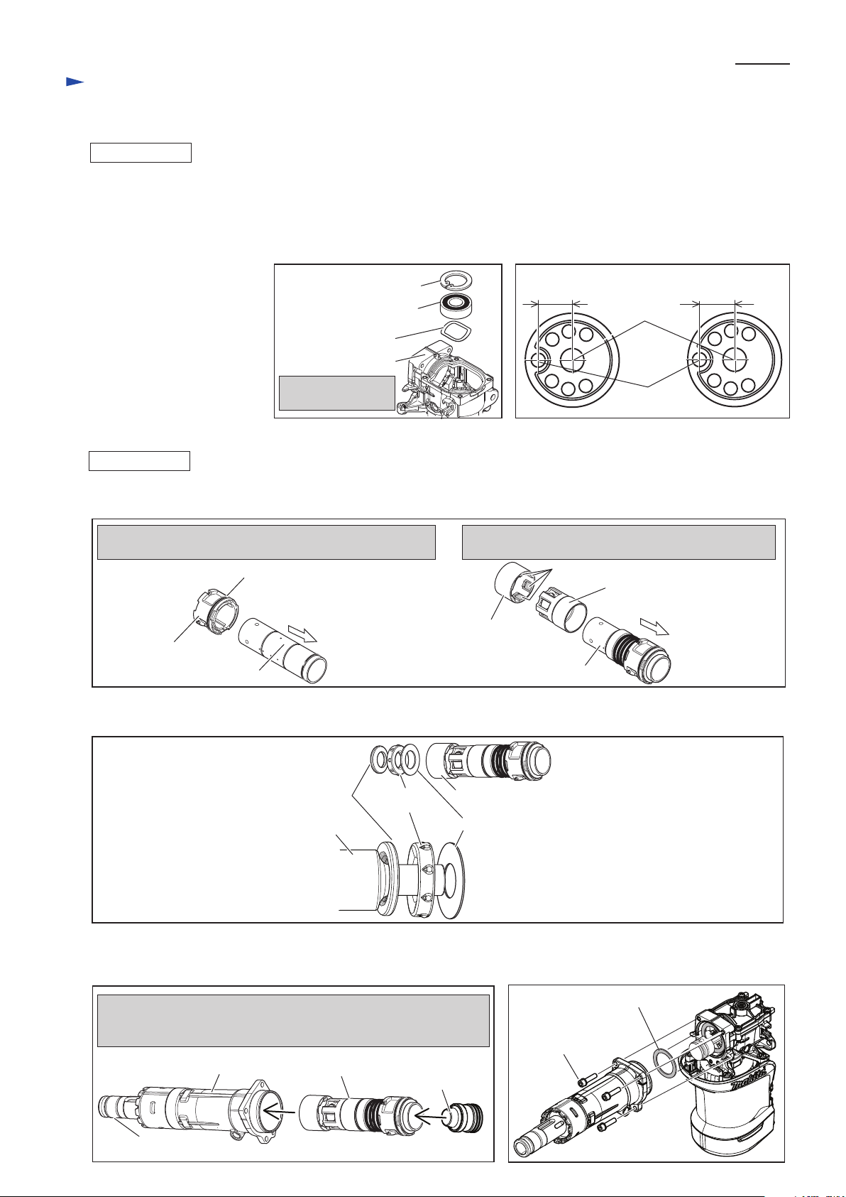
(1) Remove Tool holder cap as illustrated in Fig. 2.
Remove Handle section by loosening four 5x25
Tapping screws, and then disconnect Lead unit
from Controller.
Stand the machine upright. While pressing down Chuck cover,
remove Tool holder cap.
And then, remove Chuck cover.
Fig. 2
Handle section
Lead unit
Controller
Note: It is not necessary to disconnect Switch and
Power supply cord.
Chuck cover
Tool holder cap
P 3/ 17
Repair
[3] DISASSEMBLY/ASSEMBLY
[3]-1. Chuck section
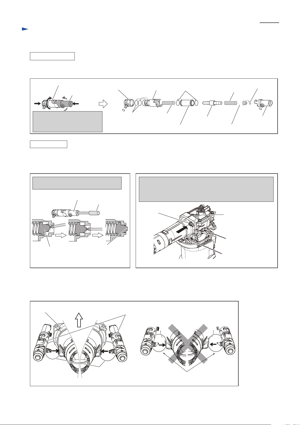
(2) Disassemble Chuck section as illustrated in Figs. 3 and 4.
2. Press down Flat washer 28 by
turning Socket wrench to make
Ring spring 25 free from the
pressure by Flat washer 28.
3. Remove Ring spring 25 using
1R003 with 1R212.
4. Remove Flat washer 28, Rubber ring 28 and Chuck ring.
Remove Spring guide,
Compression spring 52
and Plate.
Remove four Steel balls 4.8
with Slotted screwdriver
magnetized by 1R288.
Remove Change ring
together with Lock ring.
And separate Lock ring
from Change ring.
While pressing down Spring
guide, push out Tool retainers
by screwdriver inserted from
Tool holder.
Fig. 3
Fig. 4
Flat washer 28
1R003
Flat washer 28
1R363
1. Pulling down Chuck cover, install 1R363
in the same way of SDS-MAX bit installation.
Socket wrench
Spring guide
Ring spring 25
Ring spring 25
Rubber ring 28
Chuck ring
Tool retainer
Spring
guide
Spring
guide
Plate
Compression
spring 52
Steel ball 4.8
(4pcs.)
Screwdriver magnetized
by 1R288
Lock ring
Change ring
5x25 Tapping screw (4pcs.)
1R212
Page 4
P 4/ 17
Repair
DISASSEMBLING
(1) Disassemble Chuck section. (Figs. 2, 3 and 4)
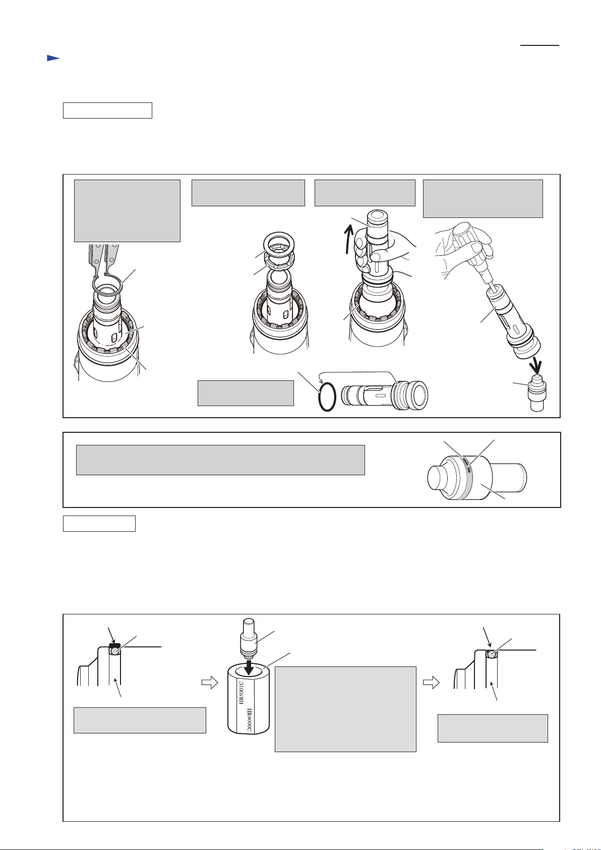
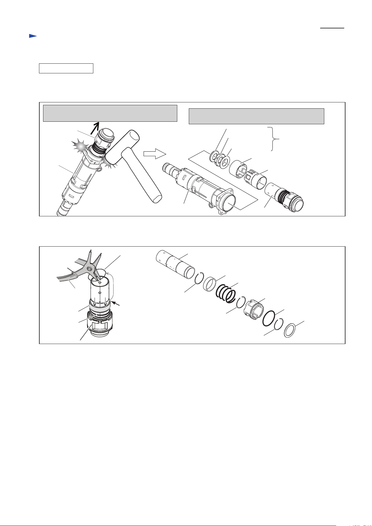
(2) Removing Retaining ring R-42, disassemble Tool holder section and take out Impact bolt. (Fig. 5)
(3) Remove Fluoride ring 28 and O ring 23 from Impact bolt when Fluoride ring 28 is worn out as illustrated in Fig. 6.
2. Remove Flat washer 29
and Rubber ring 28.
3. Pull off Tool retainer
from Barrel.
Fig. 5
Fig. 6
[3] DISASSEMBLY/ASSEMBLY
[3]-2 Tool holder section
1. Tool holder is fixed to
Barrel with Retaining
ring R-42.
Remove the Retaining
ring R-42 with 1R005.
Barrel
Tool holder
Impact bolt
O ring 38
5. Remove O ring 38
from Tool holder.
4. Remove Impact bolt from
Tool holder by pushing
out with Screwdriver.
Retaining
ring R-42
Flat washer 29
Flat
washer 29
Rubber ring 28
Barrel
Tool holder
O ring 23
(color: orange)
Fluoride ring 28
(the worn one)
Impact bolt
Fig. 7
ASSEMBLING
Taper sleeve (No.1R214)
Impact bolt
Fluoride ring 28 is protruded
from the groove on Impact bolt.
groove on Impact bolt
Fluoride ring 28
O ring 23
groove on Impact bolt
O ring 23
Fluoride ring 28 is fit into
the groove on Impact bolt.
Outer surface of Fluoride ring 28
(1) When particles and dust are in the inside of Barrel and Crank housing, be sure to clean them up.
(2) Fit O ring 23 into the groove of Impact bolt, and then put Fluoride ring 28 on O ring 23 as illustrated in Fig. 7.
(3) Assemble Tool holder and Chuck section by taking the reverse step of Figs. 5, 4, 3 and 2.
Note: Do not apply any grease to O ring 23, or the Fluoride ring will not shrink even using Taper sleeve.
Be sure to apply Makita grease R.No.00 to the outer surface of Fluoride ring 28 after fitting into Impact bolt.
When orange colored O ring 23 can be seen through Fluoride ring 28,
Fluoride ring 28 and O ring 23 have to be replaced with new ones.
1) Insert Impact bolt securely into
Taper Sleeve from HR5001C
marking side.
2) Hold the Impact bolt for at least
60 seconds.
3) Then pull Impact bolt out of
Taper sleeve.
Note: Once Fluoride ring is expanded,
it does not shrink by itself.
If you insert Impact bolt into Tool
holder without shrinking Fluoride
ring, Fluoride ring will be pinched
and broken, or Impact bolt will
loose smooth sliding action.
Note: If it is hard to pull out Impact bolt,
insert a round bar from the opposite
side and hit it slightly.
Note: If it is hard to pull out
Impact bolt, insert a round
bar from the opposite side
and hit it slightly.
Page 5
(1) First, disassemble Chuck section as illustrated in Fig. 2, 3 and 4.
(2) Remove Housing cover as illustrated in Fig. 9.
Fig. 9
Fig. 10
[3] DISASSEMBLY/ASSEMBLY
[3]-2 Tool holder section (cont.)
Housing cover
Remove Housing cover by unscrewing
M5x25 Hex socket Head bolt.
Active dynamic vibration absorber
comes into sight.
Insert Screwdriver into the hole of Handle side,
and push Spring guide in Active dynamic vibration
absorber to be stuck as follows:
M5x25 Hex
socket head bolt
Active dynamic vibration
absorber
Spring guide has to be removed from
Crank housing prior to the next step.
Spring guide
Spring guide tilted and stuck
in Pipe holder A
Crank housing
Insert two slotted screwdrivers between Crank housing and
Active dynamic vibration absorber, and then lever up
Active dynamic vibration absorber from Crank housing.
(3) Remove Active dynamic vibration absorbers from the both side of the machine as illustrated in Fig. 10.
[3]-3 Active dynamic vibration absorber (exclusively for HM0871C)
DISASSEMBLING
ASSEMBLING
Short end Long end
Impact bolt
(2) Assemble Tool holder section by taking the reverse step of Fig. 5.
Insert Impact bolt into Tool holder.
Note: Face the short end of Impact bolt to Hammer bit insertion side. See Fig. 8.
(3) Assemble Chuck section by taking reverse step of disassembly. Refer to Figs. 4, 3 and 2.
Fig. 8
Tool holder
Hammer bit
insertion side
P 5/ 17
Repair
Pipe holder A
Page 6
P 6/ 17
Repair
Fig. 11
Fig. 12 Fig. 13
Fig. 14
DISASSEMBLING
ASSEMBLING
[3] DISASSEMBLY/ASSEMBLY
[3]-3 Active dynamic vibration absorber (exclusively for HM0871C) (cont.)
(4) The removed Active dynamic vibration absorber can be disassembled as illustrated in Fig. 11.
(1) Assemble a pair of Active dynamic vibration absorber. (Fig. 11)
(2) Before fitting Active dynamic vibration absorber to the machine, take the steps in Figs. 12 and 13.
Pipe holders can be separated by
turning and pushing Pipe holders
each other illustrated above.
Pipe holder B
Pipe holder A
Pipe holder A
Pipe 16
Counter weight
Compression
spring 12
Pipe holder support
O ring 18
O ring 18
Pipe holder B
Compression spring 12
Spring guide
O ring 8
Crank cap side
Spring guide
Spring guide to be
protruded from
Pipe holder A
Protrude Spring guide from Pipe holder A
with Screwdriver
Tighten M6x25 Hex socket head bolt designated with black
arrow in order to align Insertion hole for Pipe holder support with
Insertion hole for Pipe holder A. Then tighten the other M6x25
M6x25 Hex socket head bolts (3pcs.).
Pipe holder A
Screwdriver
Insertion hole
for Pipe holder A
Protrusion as distinction
of the direction of Barrel.
Insertion hole
for Pipe holder
support
Connector of
Pipe holder support
Note: Do not insert Pipe holder supports
as illustrated above.
Barrel
(3) Insert Pipe holder supports of Active dynamic vibration absorbers to holes on Barrel and Crank housing. (Fig. 14.)
And push Active dynamic vibration absorbers parallel to the machine so as to pass the protrusion of Spring guides
through the holes of Crank housing. (Refer to Figs. 12 and 10.)
M6x25 Hex socket
head bolt
Active dynamic
vibration absorbers
Page 7

P 7/ 17
Repair
Fig. 15
Fig. 16
DISASSEMBLING
[3] DISASSEMBLY/ASSEMBLY
[3]-4 Piston, Striker, Cylinder
Remove Barrel from Crank housing
M6x25 Hex socket
head bolt (4pcs.)
(1) Disassemble Chuck section as illustrated in Figs 2, 3 and 4.
(2) Remove Housing cover as illustrated in Fig. 9. In case of HM0871C, disassemble Active dynamic vibration absorber as
illustrated Figs. 9 and 10.
(3) Striker and Piston can be disassembled as illustrated in Figs. 15 and 16.
Note: It is not necessay to remove Tool holder from Barrel.
Barrel
Crank cap
Remove Crank cap, Seal ring, Air pipe
and Flat washer 34 from Crank housing.
O rings on Piston can be
replaced .
Seal ring
Flat washer 34
Air pipe
Turning Crank shaft,
set Piston to the closest
position to Barrel side.
Barrel
Striker
O ring 24
Striker
Separate Striker from Barrel, and then
remove O ring 24 from Striker.
M4x18 Pan
head screw (4pcs.)
Crank housing
O ring 24
Piston
Piston
Pin 8
O ring 26
Connecting rod
Connecting rod
Crank
shaft
And remove Piston together
with Connecting rod.
Barrel
side
Piston
Crank shaft
Note: Do not lose Flat washer 34 between
Crank housing and Barrel.
Page 8
P 8/ 17
Fig. 17
Fig. 18
DISASSEMBLING
[3] DISASSEMBLY/ASSEMBLY
[3]-4 Piston, Striker, Cylinder (cont.)
Remove Cylinder section by tapping Barrel using
plastic hammer. Pay attention to the tapped position.
Ring 20, Rubber ring 20, Flat washer 23, Guide ring,
Slide sleeve are removed from Cylinder section.
(4) Separate Cylinder section from Barrel. The parts on Tool holder side can be removed from Cylinder 32 as per the right
illustration in Fig. 17.
(5) Pressing down Ring 36, remove Ring spring 34 (A) from Groove (A) on Cylinder 32 with 1R291.
The components of Cylinder section can be separated by removing Ring spring 34 (B) and (C). (Fig. 18.)
Barrel
Barrel
Ring 20
fit to the long drum side
of Impact bolt
Guide ring
Slide sleeve
Cylinder 32
Rubber ring 20
Flat washer 23
Cylinder Section
Ring 36
Groove (A)
on Cylinder 32
Ring spring 34
1R291
Compression
spring 37
Cylinder guide
Repair
Cylinder 32
Ring spring 34 (A)
groove(A)
groove(B)
groove(C)
Ring spring 34 (B)
Ring spring 34 (C)
Ring 36
Compression
spring 37
Cylinder guide
O ring 46
Ring washer 34
(See Fig. 15.)
Page 9

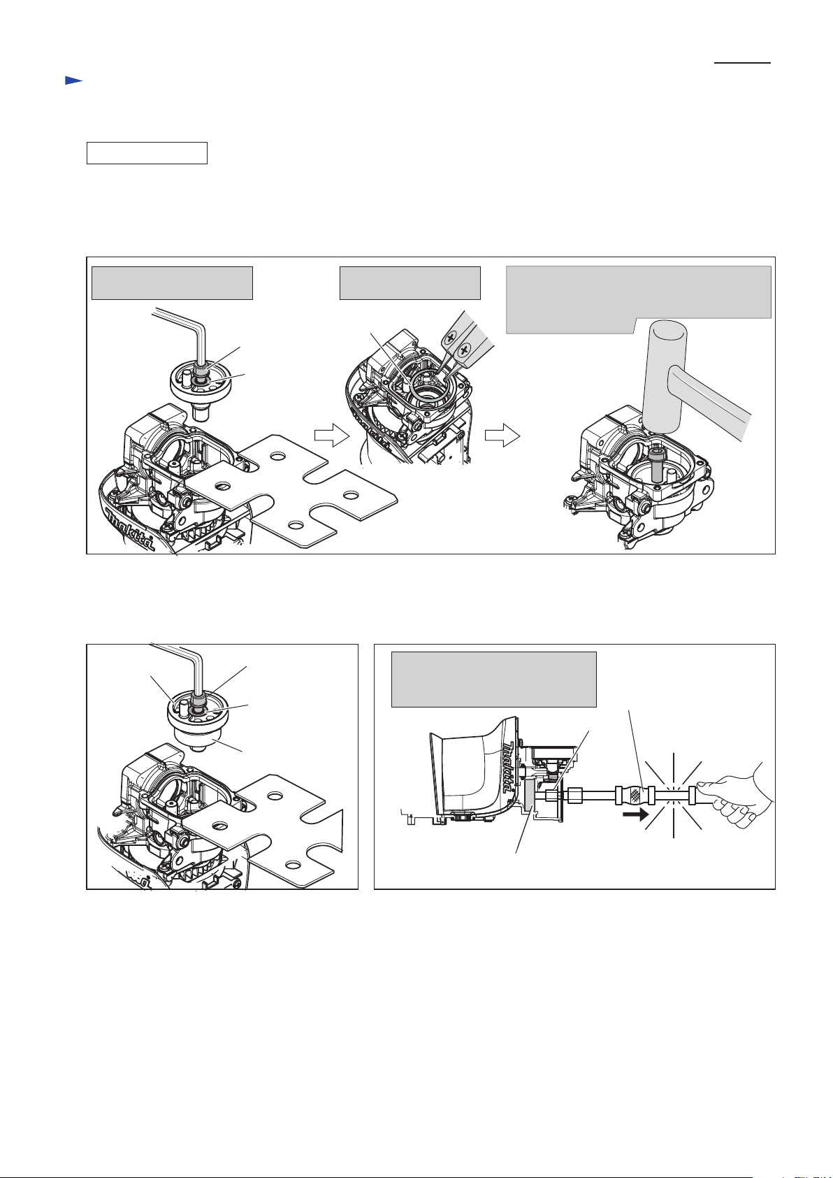
1. Keeping Crank shaft in the condition Crank pin is at the closest position to Barrel side,
hold Armature by inserting a bar into Armature fan.
P 9/ 17
Fig. 19
Fig. 20
DISASSEMBLING
[3] DISASSEMBLY/ASSEMBLY
[3]-5 Crank shaft
4. Tighten the M8x40 Hex socket head bolt using
Hex wrench until Crank shaft is pulled off from
Ball bearing 6203LLU in Crank housing.
(1) Separate Barrel from Crank housing. (Fig. 15)
(2) Remove Crank cap, Seal ring, Air pipe and Flat washer 34 from Crank housing. (the left illustration in Fig. 16)
(3) Remove Piston together with Connecting rod ( the right illustrations in Fig. 16)
Note: Turn Crank shaft so that the crank pin is at the closest position to Barrel side for easy removal of Connecting rod.
(4) remove Crank shaft as illustrated in Figs. 19 and 20.
Bar to hold Armature fan
2. Put 1R139 on Crank housing,
facing 13mm notch to Barrel side.
Crank pin at the closest position
to Barrel side
Barrel
side
Bar to hold
Armature fan
Bar to hold
Armature fan
M8x40 Hex
socket head bolt
Flat washer 8
Crank pin is locked
by 1R139.
3. Putting Flat washer 8 on 1R139, drive M8x40
Hex socket head bolt to the center hole of
Crank housing through Flat washer 8.
Hex wrench
Repair
Page 10
Crank shaft can be removed
as illustrated below.
Remove Retaining ring
R-40 with 1R005.
Loosening M8x40 Hex socket head bolt
halfway, insert Crank shaft into the remaining
Ball bearing 6203LLU by tapping the M8x40
Hex socket head bolt.
P 10/ 17
Fig. 21
Fig. 22
Fig. 22A
DISASSEMBLING
[3] DISASSEMBLY/ASSEMBLY
[3]-5 Crank shaft
Setting 1R132 into the inner ring
of Ball bearing 6203LLU, pull off
Ball bearing 6203LLUwith 1R089.
(1) Separate Barrel from Crank housing as per the left illustration in Fig. 15.
(2) Remove Crank cap, Seal ring Air pipe and Flat washer 34 from Crank housing as per the left illustration in Fig. 16.
(3) Remove Piston together with Connecting rod as per the center and right illustrations in Fig. 16.
(4) remove Crank shaft as illustrated in Figs. 19 and 20.
M8x40 Hex
Socket head bolt
(5) Lock Armature, and set 1R139, Flat washer 8 and M8x40 Hex socket head bolt as illustrated in Fig. 20 again,
tighten the M8x40 Hex socket head bolt with Hex wrench. So Ball bearing 6203LLU are removed as illustrated
in Fig. 22. If it is difficult to remove as illustrated in Fig. 22, remove Ball bearing 6203LLU as illustrated in Fig. 22A.
Flat washer 8
Retaining ring R-40
M8x40 Hex
socket head bolt
Flat washer 8
Crank shaft
Ball bearing 6203LLU
1R132
1R089
Ball bearing 6203LLU
Repair
Page 11
P 11/ 17
Assemble Cylinder guide to Cylinder 32 so that O ring 46
side of Cylinder guide faces Crank housing side.
(1) Cylinder section can be assembled as illustrated in Fig. 25.
Cylinder guide
Cylinder 32
O ring 46
Crank housing
Side
Crank housing
side
Align the six protrusions of Guide ring to Slide sleeve
and assemble Guide ring to Slide sleeve.
Guide ring
Slide sleeve
Cylinder 32
Six protrusions
[3]-6 Cylinder section
Fig. 25
Repair
(2) When assembling the parts which accept Impact bolt, put them into Guide ring as illustrated in Fig. 26.
(3) Assemble Cylinder section to Barrel as illustrated in Fig. 27.
(4) Assemble Flat washer 34 into Crank housing, and then assemble Barrel to Crank housing as illustrated in Fig. 28.
Fig. 26
Fig. 27 Fig. 28
Impact bolt
Ring 20
Note: Ring 20 has to be assembled
so that its inner side can be fit to
Impact bolt as illustrated right.
Note: Rubber ring 20 has to be
assembled so as to contact closely
to Ring 20 without any gap.
Rubber
ring 20
Flat washer 23
Tool holder
Insert Cylinder section into Barrel.
Insert Striker into the Cylinder so that the protrusion of Striker faces
Tool holder side.
Flat washer 34
Guide ring
M6x25 Hex socket
head bolt (4pcs.)
ASSEMBLING
ASSEMBLING
(1) Assemble Crank housing section as illustrated in Fig.s 23.
Be careful that Crank shaft of HM0870C is different from that of HM0871Cas illustrated in Fig. 24.
(2) Assemble Piston to Crank pin while referring to the right illustration in Fig. 16.
(3) Assemble Air pipe, Seal ring and Crank cap. And secure them with M4x18 Pan head screws. Refer to the left illustration
in Fig. 16.
Retaining ring R-40
Set the above parts
in place.
Ball bearing 6203LLU
Wave washer 30
Crank housing
Fig. 23
Fig. 24
HM0871CHM0870C
17.5mm
Center of
Crank shaft
Center of
Crank pin
17mm
[3] DISASSEMBLY/ASSEMBLY
[3]-5 Crank shaft (cont.)
Protrusion
of Striker
Cylinder sectionBarrel
Page 12
P 12/ 17
DISASSEMBLING
DISASSEMBLING
[3] DISASSEMBLY/ASSEMBLY
[3]-7 Controller
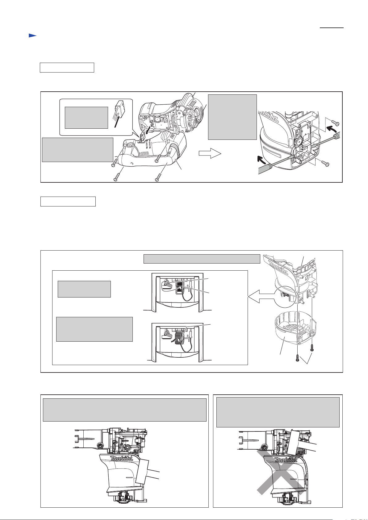
Controller can be removed as illustrated in Fig. 29.
Fig. 29
Fig. 30
Disconnect
Connector
From Controller.
Disassemble Handle section
by unscrewing four 5x25
Tapping screws.
Unscrewing 4x12
Tapping screws,
remove Controller
by levering up
with two Slotted
screwdrivers.
Handle section
[3]-8 Armature
(1) Disassemble Chuck section as illustrated in Fig. 2, Fig. 3, Fig. 4. However, no need to remove Tool holder.
(2) Disassemble Housing cover as illustrated in Fig. 9.
(3) In case of HM0871C, remove Active dynamic vibration abosorber after removing Housing cover. See Fig. 10.
(4) Disconnect Carbon brush from Armature’s commutator as illustrated in Fig. 30.
Carbon brush
Carbon brush
Spiral spring
Detach Spiral spring
from Carbon brush.
Note: It is not necessary to remove
Carbon brush completely from
Brush holder set.
By pulling Carbon brush,
disconnect its contact with
Armature's commutator.
Disassemble Rear cover from Motor housing.
Rear cover
4x18 Tapping screw(2pcs.)
Motor housing
Repair
(5) Separate Motor housing by tapping with Plastic hammer as illustrated in Fig. 31R.
Fig. 31R Fig. 31F
Tap Motor housing at the illustrated portion with Plastic hammer.
Armature can be removed together with Crank housing from
Motor housing.
Do not tap Motor housing at the edge portion
illustrated below.
The edge of Motor housing is so thin that it may
be broken.
Page 13

P 13/ 17
Repair
DISASSEMBLING
[3] DISASSEMBLY/ASSEMBLY
[3]-8 Armature (cont.)
Fig. 32
Fig. 33
Fig. 32A
(6) Disassemble Armature from Crank housing as illustrated in Fig. 32.
If it is difficult to remove as illustrated in Fig. 32, Crank shaft has to be removed in the following process.
1. Disassemble Barrel, Cylinder section as illustrated in Fig. 15.
2. Disassemble Crank cap, Seal ring, Air pipe and Piston as illustrated in Fig. 16.
3. Remove Crank shaft from Crank housing as illustrated in Figs. 19 and 20.
4. Remove Armature using 1R306, 1R239, 1R023 and arbor press as illustrated in Fig. 32A.
Crank housing
Armature can be removed by striking Crank
housing with plastic hammer.
Crank housing
Put Crank housing on 1R023.
Set 1R306 to ram of Arbor press.
Press down Armature using 1R239.
Armature
1R239
1R306
Armature
1R023
(7) Armature can be disassembled as illustrated in Fig. 33.
Flat washer 12
Ball bearing 6203LLB
Fan 76
Insulation washer
Ball bearing 608DDW
Page 14

P 14/ 17
Fig. 34
[3]-9 Handle section
(1) Disassemble Handle section as per the left illustration in Fig. 29.
(2) Remove Handle cover by unscrewing 4x18 Tapping screw to replace the electrical parts in Handle. See Fig. 34.
Power supply cord
Remove 4x18 Tapping screw and Handle cover.
Switch and Power supply cord can be replaced.
Rubber pin 4 comes out after removing Switch.
4x18 Tapping
screw
Switch
Rubber pin 4
Handle cover
Repair
ASSEMBLING
Fig. 35
Fig. 36
Unscrew 5x25 Tapping screws. So Vibration absorbing handle can be disassembled in five parts as illustrated below.
(3) In case of HM0871C, the Vibration absorbing handle section can be disassembled as illustrated in Fig. 35.
Assemble Handle section as illustrated in Fig. 36.
Dust Cover
Support
Dust cover support
Assemble Dust cover support to Handle base, facing its Triangle mark to Back side.
When assembling Dust cover to Dust cover support, face the >NBS< mark to
Triangle mark on Dust cover support.
Dust cover
Dust cover
Handle
Handle
cover
5x25 Tapping
screw (2pcs.)
Flat washer 5 (2pcs.)
Handle base
Compression
spring 11
“>NBS<” Mark
Triangle mark
Back side
Page 15
P 15/ 17
Repair
[3] DISASSEMBLY/ASSEMBLY
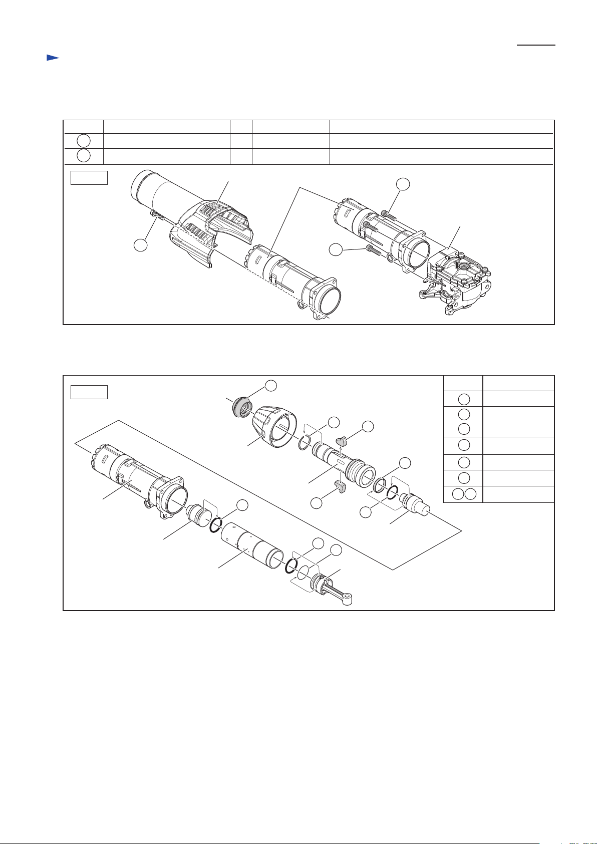
[3]-10. Fastening torque
[4] MAINTENANCE PROGRAM
Replacing the following parts is recommended when Carbon brush is replaced.
Wipe off the old grease in the machine, and then apply the fresh grease in accordance with [2] LUBRICATIONS.
Fig. B
Fig. A
Item No.
1
3
Barrel
Description
Fasten the following bolts to the specific fastening torque.
7.8 - 11.7 N.m
M6 x 25 Hex socket head bolt
Barrel
Crank housing complete
Housing cover
4 Fastening Barrel to Crank housing complete
2.9 - 3.4 N.m
M5 x 25 Hex socket head bolt 1 Fastening Housing cover to Barrel
Item No. Fastening torqueQ’tyDescription Use for
25
42
42
25
25
Striker
Cylinder 32
Piston
Impact bolt
Tool holder
Chuck cover
7
19
20
7
31
50
51
1 Tool holder cap
3 Ring spring 25
7
19 Fluoride ring 28
20 O ring 23
O ring 24
31 50
51 O ring 26
Tool retainer
Page 16

Circuit diagram
Wiring diagram
P 16/ 17
Blue Lead wire is used
for some countries.
Brown Lead wire is used
for some countries.
Terminal block
Power supply cord
Polyethylene tube
White
Color index of lead wires' sheath
Black
Fig. D-2
Fig. D-1
HM0870C
without No Load Speed
Suppression
Note in wiring
6 3 1 9 2 9 - 5
LOT No.
LOW
6 3 1 9 3 0 - 0
LOT No.
HIGH
HM0871C
with No Load Speed
Suppression
6 3 1 9 3 1 - 8
100 - 130V
220 - 240V
LOT No.
LOW
6 3 1 9 3 2 - 6
LOT No.
HIGH
Indication for 110V-127V area
Indication for 220V-240V area
HM0870C
without No Load Speed
Suppression
HM0871C
with No Load Speed
Suppression
Controller for HM0870C is different from that for HM0871C.
Controller
Page 17

Wiring diagram
P 17/ 17
Fig. D-3
Handle
Lead Unit
Fig. D-4
Polyethylene Tube Ø8-30
Connector
for connecting to Switch
for connecting to Terminal block
Pass the Lead wires of Lead unit through Polyethylene tube illustrated below.
Lead unit’s Lead wires
Lead unit’s Lead wires have to
be put on both side of Boss,
And connect them to Switch
and Terminal.
Lead unit’s Lead wires bundled
with Polyethylene tube has to put
under Terminal block.
Boss
Terminal block
Sponge sheet
Connector of
Lead unit
Put the following Lead wires
of Lead unit into Sponge sheet.
* Lead wire (black) for connecting to Switch
* Lead wire (black) for connecting to Terminal
block
* Lead wire (white) for connecting to Switch
The Lead wires have
to be tightened in this
area.
Polyethylene
tube
 Loading...