

Makita HB500 Original Instruction
1
WARNING:
For your personal safety, READ and UNDERSTAND before using.
SAVE THESE INSTRUCTIONS FOR FUTURE REFERENCE.
A Guide to
Good drillinG Practice
To get the best possible performance from your new Magnetic
Drilling Machine, please read this carefully BEFORE using the drill.
HB500
Magnetic Drilling Machine
ORIGINAL INSTRUCTIONS
®
Fr Instructions originales
de Ursprüngliche Anweisungen
ne Originele instructies
2
en
3
en
To help you get the best possible performance
from your new Magnetic Drilling Machine, this
guide contains simple, sensible pointers for
the safe, effective and long term use of the
equipment.
Please read it carefully BEFORE using the
drill.
• Ensure that you have observed all the general
and specific safety procedures.
BEFORE YOu StaRt
If you are unfamiliar with the use of annular
(or broaching) cutters, take a few minutes to
read this guide - you will benefit from the better
performance and longer life of the tool if you
understand the concept.
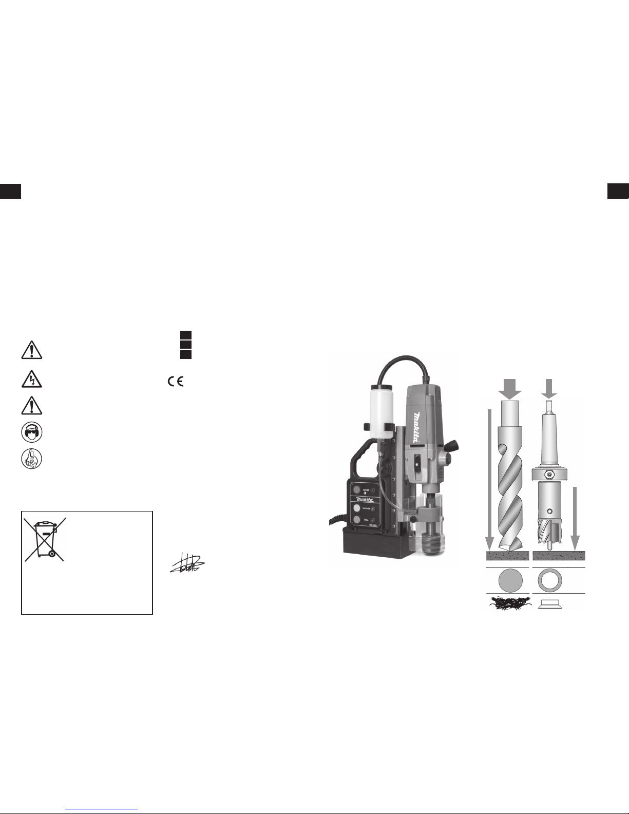
Ann ula r cutters only cut materia l at the
periphery of the hole, rather than converting
the entire hole to shavings. As a result the time
and energy required to make the hole is lower
than for a traditional twist drill.
The broa ching capacity of a machine is
therefore greater than the twist drill capacity.
The slug ejected after the cut also has a higher
scrap value than shavings.
the Broach cuttinG
concePt
POWER
REQUIRED
CUTTING TIME
CUTTING TIME
MATERIAL
REMOVED
hB500 sPeciFications
Cutter capacity - 12 – 50mm
Chuck Capacity - 5/8” (with adapter)
‘No load’ speed - 350/650 rpm
Power consumption - 1150w
Clamping force
- 9300N (950kg)
L x H x W (mm) - 290 x 450 x150
Weight - 18.5 kg
Voltage - 110/230v
Includes:
Warranty, Carrying case, Hex Wrenches,
Safety strap & guard, Cutting Oil
RECYCLING
In ob se rva nc e of E ur ope an
Dire ct iv e 2002 /9 6/ EC o n
waste electrical and electronic
equipment and its implementation
in acco rdanc e with na ti onal
law, e lec tric equip men t tha t
has reached the end of its life must be collected
separatel y and returned to an environment ally
compatible recycling facility.
WEEE Compliance Certificate:- on request
All magnetic drilling systems are fully compliant
with ROHS regulations.
• Due to our continui ng p rogramme of research and
development, these specifications are subject to change
without notice.
cOntEntS
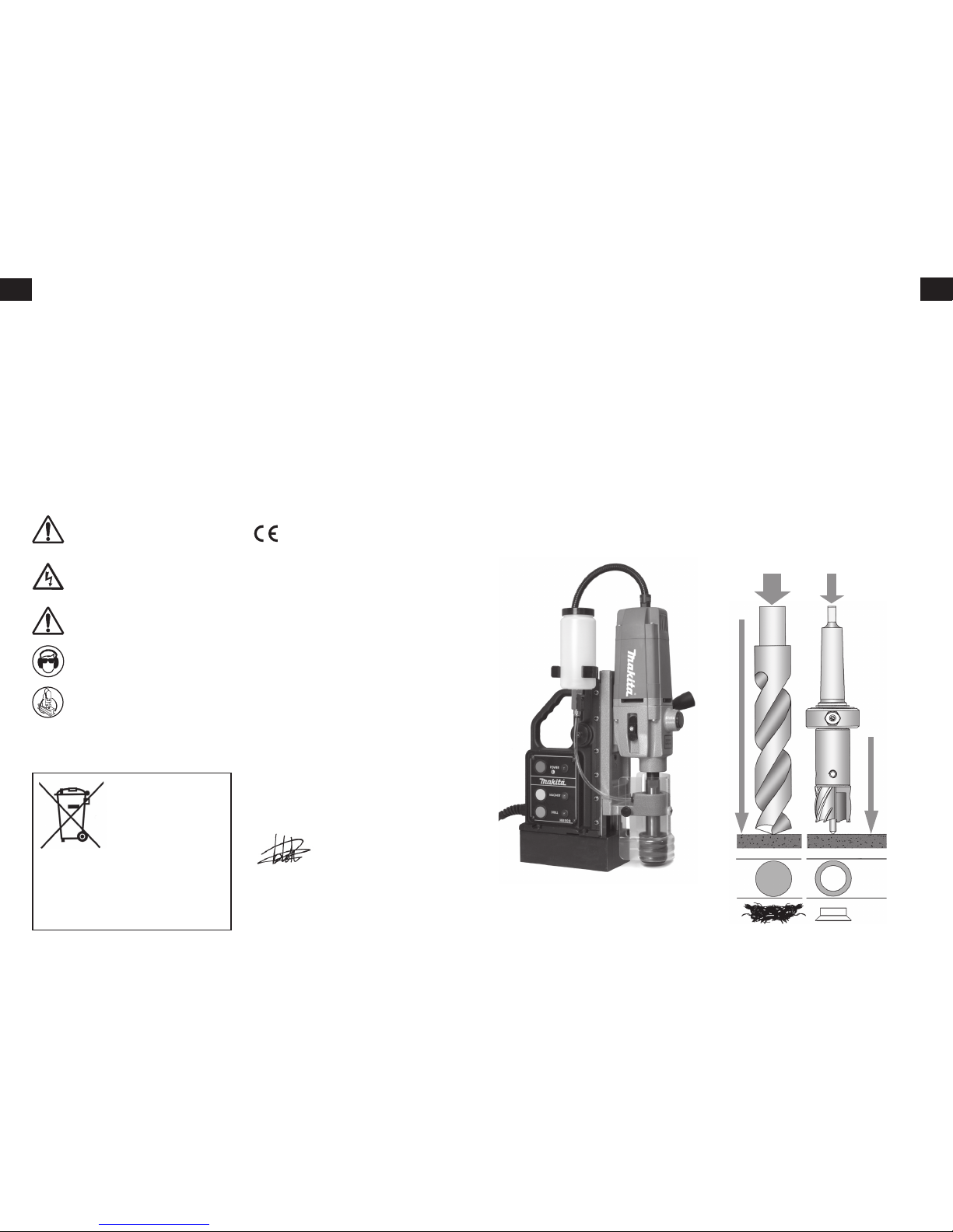
Explanation of the pictograms on the
specification plate of the Makita HB500
DANGER!
Indicates an imminent danger or risk to
life and health of a general nature.
ELECTRICAL DANGER!
This means a direct pending danger or
risk to life due to electricity.
CAUTION!
Indicates a possible danger or risk of
slight injury or damage to property.
WEAR EYE & EAR PROTECTORS
USE SAFETY STRAP!
to attach the tool to the workpiece.
EC Declaration of Conformity
We the Makita Corporation as the responsible
manufacturer declare that the following Makita
machine:
Designation of Tool: Magnetic Drilling Machine
Model No./ Type: HB500
conforms to the following European Directives:
2006/42/EC, 2004/108/EC
and has been designed in compliance with:
EN 55014-1:2006, EN 55014-2:1997 + A2:2008,
EN 61029-1:2009, EN 61029-2-6:2010,
EN 61000-3-2 & EN 61000-3-3, and with the essential
Health & Safety requ irements.
And is manufactured in accordance with the following
standards or standardised documents:
EN60745.
Makita International Europe Ltd,
Michigan Drive, Tongwell,
Milton Keynes,
MK15 8JD,
England
30th July 2011
Tomoyasu Kato
Director
Makita Corporation
3-11-8, Sumiyoshi-cho,
Anjo, Aichi, JAPAN
3. The Broach Cutting Concept
4. Safety & Maintenance
6. Material and Cutting speeds
7. Feeds and Speeds
8.
Fitting Safety Guard & Strap and Oil Bottle
9. Fitting Cutters
10. Starting the Cut
11. Stopping the machine
12. Motor diagram & parts list
14. Stand diagram & parts list
17.
Fr Instructions françaises
30.
de Deutsch Anweisungen
44.
ne Nederland instructies

4
en
5
en
MaGnetic drill
saFety instructions
• Always inspect the whole unit before use.
• Regular maintenance is essential - check nuts,
screws etc. for tightness before each use.
• Check cable and plug for damage.
• Never use blunt or damaged cutters.
• Never use a larger diameter cutter than
specified for the machine
• Always use the safety guards (where fitted)
and ensure they are operating correctly.
• Always wear goggles and gloves
• Remove rings, watches, ties etc. that could
tangle in the moving parts.
• Secure the unit with the safety strap before
drilling.
• The machine is for use on steel from 6 mm
thick, with no air gap between the magnet core
and the workpiece. Curvature, paint and surface
irregularities create an air gap. Keep the air gap
to a minimum.
• Keep the magnet and workpiece clean & free
of debris and swarf.
• Do not start the motor before ensuring that
the magnetic stand is clamped firmly to the
workpiece.
• Only use a general, non-oil-based metal
cutting coolant diluted with water.
• While drilling vertically or overhead, use a
cutting paste or an appropriate coolant spray.
• Always disconnect from the power source
before changing cutters or working on the
machine.
• In the event of a jammed cutter, disconnect
from the power supply, and free the jam before
reconnecting the tool.
• On swivel machines, ensure that the swivel
base is locked in the required position.
• Do not attempt to change speed while the
drill is running.
• Only use accessories recommended by the
manufacturer.
• Never lift or carry the unit by the power cord,
always use the handle.
• Never modify the tool in any way.
• Occasionally apply a few drops of oil to the
rack toothing.
• The bearings of the feed shaft are selflubricating and must not be greased
• Grease the sliding surface of the carriage
with MOLYCOTE grease.
• When not in use or being transported the
unit should be kept in the case supplied.
• After use ensure unit is clean of swarf and
dirt.
• Parts that are worn or damaged should
be rep laced immedi at ley wit h gen ui ne
manufacturer’s replacements.
• Ensure all cutting edges are sharp when in
operation. Using blunt cutting tools may lead
to an overload of the motor.
• After eve ry 30 minut es running, it is
recommended that the machine is laid on its
side to permit grease to run across the gear
train.
• After repeated use, the cradle may become
loose. This is remedied by adjusting the tension
screws on the side of the body. Put 2.5mm
hex wrench into head of cradle retaining nuts,
using 8mm Spanner undo the locking nuts
anti-clockwise, holding the hex wrench without
moving grub screws.
Using the hex wrench gently tighten screws in
series until the cradle moves freely in the slide
but does not allow the motor to wobble.
Whe n adju stment is complete re-tighten
locking nuts clockwise, ensuring the grub
screws do not move from their new positions.
Maintenance
instructions
IMPORTANT! – TO PREVENT DAMAGE TO THE CIRCUITRY, NEVER USE ELECTROMAGNETIC DRILLING
MACHINES AND WELDING EQUIPMENT ON THE SAME WORKPIECE SIMULTANEOUSLY.
General Power tool saFety instructions
1. KNOW YOUR POWER TOOL
Read and understand the owner’s manual and
labels fixed to the tool. Learn its application and
limitations as well as the potential hazards .
2. EARTH ALL TOOLS
Ensure that (where applicable) suitable earthed
cords and plu gs are used and cor rectly
connected.
3. KEEP GUARDS IN PLACE (where applicable),
in working order and in correct adjustment and
alignment.
4. REMOVE ADJUSTING KEYS AND WRENCHES.
Form a habit of checking to see that keys and
adjusting wrenches are removed from tool
before turning it on.
5. KEEP WORK AREA CLEAN
Cluttered areas and benches invite accidents.
Floor must not be slippery due to oils, or dust.
6. AVOID DANGEROUS ENVIRONMENT
Don’t use power tools in damp or wet locations
or expose them to rain. Keep work area well
lighted. Provide adequate surrounding work
space.
7. MAKE WORKSHOP SAFE
Use padlocks, master switches, remove keys.
Visitors should be a safe distance from work
area
8. DON’T FORCE TOOL
It will do the job better and more safely at the
rate for which it was designed.
9. USE CORRECT TOOL
Don’t force tool or attachment to do a job it
was not designed for.
10. WEAR PROPER APPAREL
Do not wear loose clothing, gloves, neckties or
jewellery (rings, wristwatches) which may get
caught in moving parts. NONSLIP footwear is
recommended.
Wear protective hair covering to contain long
hair. Roll long sleeves above the elbow.
11. USE SAFETY GOGGLES (Head Protection)
Wear approved safety goggles at all times.
Everyday eyeglasses only have impact resistant
lenses, they are NOT safety glasses. Also, use
face or dust mask if cutting operation is dusty,
and ear protectors during extended periods
of operation.
12. SECURE WORK
Use clamps or a vice to hold work when
practical. It’s safer and frees both hands to
operate tool.
13. DON’T OVERREACH
Keep proper footing and balance at all times.
14. MAINTAIN TOOLS WITH CARE.
Keep tools sharp and clean for best and safest
performance. Follow instructions for lubricating
and changing accessories.
15. DISCONNECT TOOLS
When not in use, before servicing and when
changing accessories such as bits and cutters,
disconnect tools from the power supply.
16. USE RECOMMENDED ACCESSORIES
Consult owners manual for recommended
accessor ies. Follow the in struc tions that
accompany the acc es sories. The use of
improper accessories may cause hazards.
17. CHECK DAMAGED PARTS
Before further use of the tool, a guard or
other part that is damaged should be carefully
checked to ensure that it will operate properly
and perform its intended function. Check for
alignment of moving parts, binding of moving
parts, breakage of parts, mounting, and any
other conditions that may affect operation. A
guard or other part that is damaged should be
properly repaired or replaced.
18. NEVER LEAVE TOOL RUNNING
UNATTENDED.
Turn power off. Don’t leave the tool until it
comes to a complete stop.
6
en
7
en
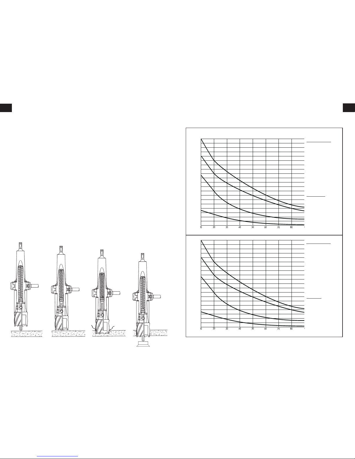
Feeds and sPeeds
PLEASE NOTE: These figures are quoted as a starting point. Actual performance will be dictated by material
type, thickness and hardness, application and cutter condition.
Speed (RPM)
MATERIAL
Feed rate (mm/min)
ALUMINIUM - 60
BRASS - 45
MILD STEEL - 24
HI TENSILE STEEL
- 9
Cutting SpeedS
Suggested speed rates for varying cutter sizes/materials
Speed (RPM)
Cutter Diameter (inches)
MATERIAL
Feed rate (inches/min)
ALUMINIUM
-
23/
8
“
BRASS
-
13/
4
“
MILD STEEL
-
1”
HI TENSILE STEEL -
3
/8 “
TOOL FEED RATE
(Imperial)
TOOL FEED RATE
(Metric)
Cutter Diameter (mm)
1000
900
800
700
600
500
400
300
200
100
100
1000
900
800
700
600
500
400
300
200
100
100
• The ease with which material can be drilled
is dependant on several factors including
ten sile streng th and abrasion resist ance.
Whilst hardness and/or strength is the usual
criterion, wide variations in machinability can
exist among material showing similar physical
properties.
• The cutting conditions can be dependent
upon requirements for tool life and surface
finish and further restricted by the rigidity of the
tool and work piece, lubrication and machine
power available.
• The harder the material the lower the
cutting speed. Some materials of low hardness
contain abrasive constituents leading to rapid
cutting edge wear at high speeds. Feed rates
are governed by rigidity of set up, volume of
material to be removed, surface finish and
available machine power.
• It is preferable to set and maintain a constant
surface speed (RPM) for a given material and
vary the feed rate within defined limits.
• Machine feed is measured in inches or
millimetres per minute and is the product of
RPM x number of teeth in the cutter x feed per
tooth. Too light or excessively high feed rates
will both cause premature cutter failure. Heavy
feeds on hard materials will cause chipping of
the cutting edge and excessive heat generation.
• Sle nder and long shanked cutter s are
restricted in feed rate due to deflection, and
wherever possible the largest and most robust
tool must be used. This is important for harder
materials. Steel up to 400 HB is the potential
limit for conventional M2 HSS tools.
Above 300 HB, cobalt alloy cutters should be
considered for increased tool life. In softer
grades of material, cobalt alloy cutters may give
increased output by increasing speeds and feed
rates by up to 50%. Tungsten Carbide cutters
permit surface speeds and feed rates up to
twice those for standard cutters.
Material and cuttinG sPeeds
8
en
9
en
enSure power iS off before working on the maChine
Insertion of pilot pin
• The pilot pin is used to both centre the cutter and to
eject the slug on completion of the cut. It has a flat side
to allow coolant to run down to reach the centre of the
cut where the heat is greatest. Slide the pin through the
hole in the centre of the cutter shank.
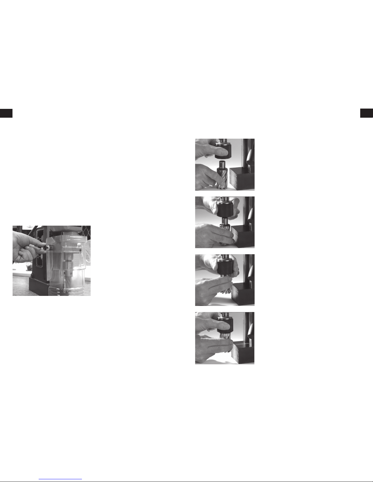
fitting the Cutter
• The Quickhitch™ arbor will accept any cutter with a
19mm diameter shank having one or more flats.
To fit a cutter, align it below the Quickhitch™ and twist the
arbor sleeve clockwise against its spring and hold, Fig. 1.
Insert shank of cutter into arbor, push it home and release
the sleeve, Fig.2.
Twist the cutter in the arbor to ensure the flat is engaged
in the locking mechanism, Fig.3.
Turn the sleeve fully anti-clockwise to complete the locking
operation, Fig.4.
To remove the cutter, simply twist the sleeve clockwise
against the spring, the cutter will be ejected.
Mark the position of the hole
• Make sure the workpiece is clean and flat and position the
machine with the pilot over the centre of the hole to be cut.
Fit the saFety strap.
applying Coolant
• Cutting oil ensures longer cutter life and enables the
slug to be ejected cleanly. A 500 ml bottle is included with
every machine.
• Oil will be automatically delivered to the cutter when
the cut commences
• When cutting on vertical surfaces or upside down, cutting
paste, gel or foam is recommended. It is best applied inside
the cutter before drilling.
• Plug the machine into the power socket and the red LED
on the electronic control panel will flash.
FittinG the cutter
Fig. 1
Fig. 2
Fig. 3
Fig. 4
Drill GuarD instructions
Ensure drill unit is isolated from power supply.
Two screws to support the guard in position,
one either side of the drill.
If necessary press the plastic guard guides into
their locating holes on ether side of the motor
cradle
Fit guard to drill as shown.
Secure guard to drill with screws and washers
supplied. DO NOT overtighten the fixing screws,
these should be loose enough to allow the
guard to rise when required. Lower guard to
drilling surface.
When drilling, the guard should always be in
contact with the surface being drilled. As the
drill is lowered, the guard will rise in relation
to the drill.
FittinG the saFety Guard
N.B. Safety strap and guards have been omitted from
the photo’s for clarity.
The supplied safety strap should be used
wherever possible as a safety precaution in the
event of a power failure releasing the magnet;
particularly in situations where the machine is
clamped onto a vertical surface or in an inverted
position.
saFety strap instructions
When the machine has been clamped to the
workpiece in the correct position for drilling,
the strap should be fed through the channel
between the body of the drill and the magnet,
then passed around a substantial part of the
workpiece. The free end should then be passed
through the buckle, pulled tight and locked.
Once the cut is complete, the strap should be
released and the machine supported before the
magnet is disengaged.
FittinG the saFety straP
The cutting oil bottle is held in a sprung bracket
attached to the top of the drill body. Fit the
bracket by removing one of the cap screws from
the top plate and replace the bolt through the
fixing lug on the bottle bracket, tightening the
bolt enough to allow some radial movement of
the bracket. The coolant tube is a push fit into
the self-seal gland at the base of the tap and a
similar fitting on the lower arbor bracket.
FittinG the oil Bottle
10
en
11
en
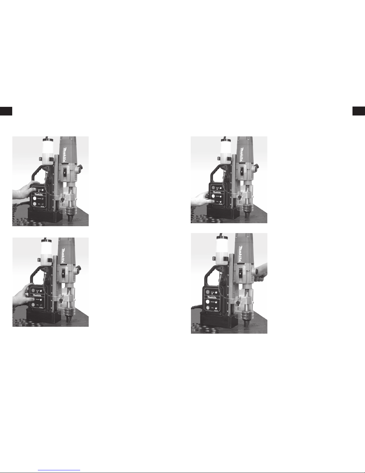
• To
power up the maChine
, press and release
the red button Fig. 5
• To
energiSe the magnet
, press and release
the yellow button - the yellow LED will light
Fig. 6.
RECHECK the pilot is still centred on the hole
position - energising the magnet can sometimes
cause the unit to move slightly from the centre
mark, reposition if necessary.
• The magnet will hold on all ferrous materials
from a minimum of 6mm (1/4”) thickness.
STARTING THE CUT
•
alwayS
lower the safety guard.
•
Start the motor
by pressing and releasing
the green button - the green LED will light
Fig. 7.
• Wind the cutter gently down to the surface
of the work and apply light pressure until
the cutter has made the initial groove in the
surface. Increase the pressure until the motor
is loaded Fig. 8.
• Maintain steady pressure throughout the rest
of the cut. Too much pressure will not speed
the cut, it will reduce the life of the cutter and
may cause damage to the motor. If the shavings
become blue add more oil.
startinG the cut
N.B. Safety strap has been omitted from the photo’s for clarity.
Fig. 5
Fig. 6
Fig. 7
Fig. 8
• to stop the motor,
PRESS & RELEASE GREEN BUTTON.
• If the cutter jams in the workpiece,
Stop the
motor
and gently raise the cutter out of the
workpiece before re-starting.
• If the power is interrupted during the cut,
the machine must be reset before the motor
will restart.
• At the end of the cut, the slug will be ejected.
Withdraw the cutter from the work piece and
stop the motor.
• To disengage the magnet, press and release
the yellow button - the magnet will not
disengage immediately, there will be a 3 second
delay before the magnet disengages along with
a continuous beep.
INCORRECT START UP OR SHUT DOWN
SEQUENCE:-
• A single beep will be heard for all operations
ca rr ie d out in the co rrec t se qu ence. A
continuous beep will sound for any incorrect
sequence.
• Neither drill nor magnet can be operated until
red power button is activated.
• When the red power button is activated, the
motor will not run until the magnet is activated.
power up the maChine
energiSe the magnet
Start the motor
Start the Cut
N.B. Safety strap has been omitted from the photo’s for clarity.
12
en
13
en
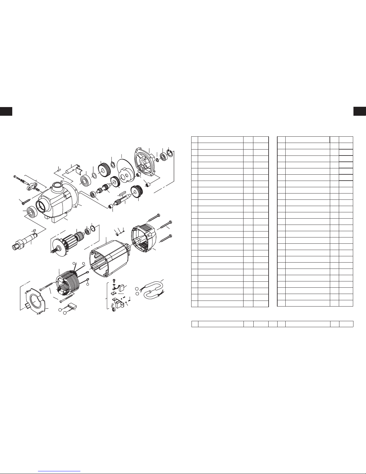
hB500 Motor Parts
D 5000 motor - 230v
EIB102-1
EIB137-A
Nr. Description
1 Cap, blue
2 Self tapping screw
HC 4,8x38
3 Rotor cpl.
4 Grooved ball bearing
608 2Z
5 Circlip
28/1,2
6 Brush holder cpl.
7 Pair of brushes. (A) 6,3x10x18
8 Spring washer
B4
9 Self tapping screw
ZM4x12
10 Contact Washer
11 Circlip
11/1
12 O-ring
22x2,5
13 Self tapping screw
HC 4,8x50
14 Grooved ball bearing
6001 2Z
15 Gearbox end shield, grey
16 Gearbox housing, grey
17 Intermediate gear
34 Z
.
18 Two pinion shaft
11/17 Z.
19 Gear changer cpl.
20 Coupling bolt cpl.
21 Dowel pin
4x12
22 Grooved ball bearing
6203 RS
23 Output shaft
24 Woodruff key
A5x5x12
Qty Part No
1 EIB202
4 EIB101
1 EIB102-2
1 UDC022
1 EIB042
2 EIB105
1 EIB106C
4 EIB172
4 EIB108
2 EIB152
1 EIB143
1 EIB111
4 EIB157
1 UDC023
1 EIB205
1 EIB204
1 EIB117
1 EIB007
1 EIB017
1 EIB008
1 EIB120
2 UDC014
1 EIB122
1 EIB034A
Nr. Description
26 Two core cable
28 Gearbox seal
29
Grease compartment barrier
30
31
32 Spindle gear
45 Z
.
33
34 Locking washer
15/22x0,2
35 Circlip
15/1
36 Gearbox shaft
13 Z.
37
38 Double gear
34/40 Z.
39
Woodruff key
A5x5x28
40 Needle bearing
HK 0810
42 Fan Cover
43 Self tapping screw
HC 3,9x60
44 Stator cpl.
45 Motor housing, blue
46 Capacitor
49 Washer
3,2
50
Self tapping screw
HC 2,9x9,5
51 Cable clip
EIB125
EIB126
EIB083
EIB004
EIB076
EIB130
EIB131
EIB132
EIB034
UDC020
EIB135
EIB136
EIB137-B
EIB203
EIB139
EIB206
EIB153
EIB085
D 5000 motor - 110v
3 Rotor cpl. 1 44 Stator cpl. 1
1
2
7, 7a
8
9
13
19
24
23
22
21
20
22
34
32
35
15
10
14
5
18
17
40
39
40
36
38
4
3
12
45
43
42
6
4
11
16
28
29
4
6
44
1
2
26
1
2
48
c
d
e
11/11
51
49
50
Qty Part No
1
1
1
1
1
1
1
1
1
3
1
2
1
1
1
1
1
1
14
en
15
en
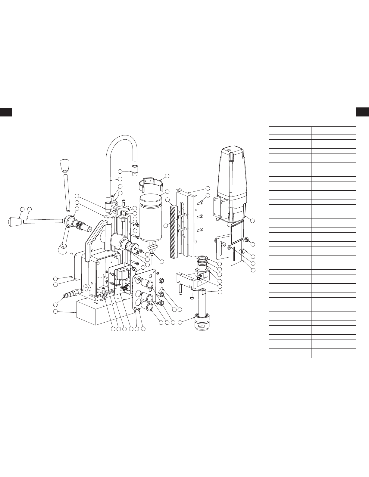
hB500 stand Parts
ITEM
NO.
QTY. PART NO. DESCRIPTION
1 1 M0034 MAGNET BASE (MIDI)
2 1 20348 BODY
3 2 M0081 PINION BUSH
4 1 M0042 LARGE PINION
5 1 M0072 PINION END CAP (DEEP)
6 1 SC620CAP M6x20 CAPSCREW
7 2 60100A BRASS STRIP
8 1 20389 GFS MINIBOR
9 3 10081 HANDLE (12mm SMALL)
10 3 10082 HANDLE KNOB
11 1 10084 TOP PLATE
12 13 SC615CAP M6x15 CAPSCREW
13 1 20305M HB500 SWITCH PLATE
14 1 10215 RACK
15 1 30046A SMALL OILCUP C/W TAP (BLACK CAP)
16 1 10076C OILCUP RETAINING CLIP
17 - - -
18 6 10085A M5x25 GRUBSCREW
19 6 10085B M5 NYLOC NUT
20 1 10231 M16 STRAIN RELIEF GLAND
21 2 40026 M16 GLAND
22 1 BD062 QUICK RELEASE ARBOR COMPLETE
23 1 M0167 HB500 D5000 SLIDE
24 1 M0516 HB500 D5000 STEADY
25 1 EIB21 / EIB22 D5000 DRILL MOTOR 110v / 240v
26 1 M0050-2 INTEGRAL COOLANT SEAL
27 1 M0521 STEADY BUSH
28 1 M0050-1 INTEGRAL COOLANT SEAL
29 1 M0066 6mm PUSH FIT FITTING
30 2 SC630CAP M6x30 CAPSCREW
31 1
MM1-5E / MM1-5G
PCB BOARD 110v / 240v
32 1 MM1_4M LED BOARD MAKITA
33 1 MM1_22 GREEN LATCHING SWITCH
34 1 MM1-17 P.C.B BACK PLATE
35 1 MM1_1 MM1 MAGNET BUTTON - YELLOW
36 1 MM1_10 MM1 POWER BUTTON - RED
37 3 MM1-3 MM1 L.E.D GROMMET
38 4 SC510BUT M5x16 BUTTON HEAD SCREW
39 1 50015C 1/8 BSP-6MM BLACK PUSH FIT
40 1 BD029 6MM OIL PIPE
41 1 M0443 CONDUIT LARGE 12MM
42 1 VISO15 DRILL GUARD
43 3 10094 M6 GUARD SPACER
44 3 BD068 M5x10 GUARD THUMBSCREW
45 1 NWP-04 WARNING PLATE
46 4 Rivet 2mm BRASS HAMMER DRIVE RIVET
47 3 BD046 P.C.B BRASS SUPPORT
48 1 Torx TORX SECURITY SCREW/WASHER
10
2
21
12
11
41
21
16
15
20
1
12
34 13 38
3
5
6
18
19
32
33 35 36
37 40
22
39
30
29
24
27
26
28
42
44
43
23
12
14
12
25
7
8
45
46
48
47
4
9
31
16
Fr
17
Fr
Afin de vous aider à obtenir les meilleures
performances de votre nouvelle perceuse
magnétique, ce guide contient des informations
simples et rai so nnables de sécur it é pour
l’utilisation efficace et durable de votre machine.
AVANT d’utiliser cette perceuse, ASSUREZ
-VOUS que vous avez bien noté et respecté
les instructions générales et les consignes de
sécurité.
aVant DE DÉMaRRER
17. Le concept du carottage
18. La sécurité et l’entretien
20. Les matières et les vitesses de coupe
21. Les avances et les vitesses
22. Mise en place du protecteur de sécurité,
de la sangle et de la bouteille d’huile
23. Mise en place des accessoires de coupe
24. Lancement de la coupe
25. Arrêt de la machine
26. Schéma du moteur et nomenclature
28. Schéma du stand et nomenclature
Si vous n’êtes pas familiarisé avec la coupe
par carottage, accordez quelques minutes à la
lecture de ce guide. En comprenant le concept
de ce genre de perçage vous augmenterez
les performances et la longévité des outils.
La fraise à carotter coupe le matériau à la
périphérie du trou, au lieu d’enlever toute
la matière comprise dans son diamètre. Il en
résulte une réduction de temps d’usinage et
d’énergie par rapport au perçage avec un foret
hélicoïdal. Avec le carottage, la quantité de
matière enlevée étant très réduite, la capacité
de perçage pour une même machine est bien
supérieure à celle obtenue avec les forets
hélicoïdaux. La valeur de la débouchure est plus
importante que celle des copeaux des forets
hélicoïdaux.
le concePt du
carottaGe
PUISSANCE
REQUISE
TEMPS DE COUPE
TEMPS DE COUPE
MATIÈRE
ENLEVÉE
caractéristiques de la
Perceuse hB500
Capacité de coupe - 12-50 mm
Capacité du mandrin - 5/8”
(avec adaptateur)
Vitesse à vide - 350/650 tr/min
Consommation de courant - 1150 W
Force de serrage - 9300N (950 kg)
L x H x l (mm) - 290 x 450 x150
Poids - 18.5 kg
Tension - 110/230V
ÉlÉments fournIs:
garantie, coffret de transport,
clés hexagonales, sangle de sécurité et protection,
huile de coupe
RECYCLAGE
En conformité avec la directive
européenne 2002/96/CE sur les
déchets à base d’équipements
électriques et électroniques et sa
mise en œuvre en respectant la
législation nationale, les appareils
électriques qui arrivent en fin de vie utile doivent être
récupérés séparément et renvoyés à un établissement
de recyclage qui respecte l’environnement.
Certificat de conformité WEEE :- sur simple demande.
Tous les appareils de perçag e ma gnétiques sont
parfaitement co mpatibles avec les réglementations
ROHS.
• Du fait de notre programme continu de recherche et de
développement, ces caractéristiques techniques peuvent
être modifiées sans préavis.
SOMMaiRE
Explication des pictogrammes de la
plaque signalétique de la perceuse
Makita HB500
DANGER !
Indique un danger ou risque imminent
pour la vie de l’être humain ou, plus
généralement, pour la santé.
DANGER ÉLECTRIQUE !
Il s’agit d’un danger ou risque direct
imminent pour la vie de l’être humain
du fait de la présence d’électricité.
ATTENTION !
Indique un danger ou risque possible de
blessure légère ou de dégât.
PORTEZ DES PROTECTIONS AU NIVEAU
DES YEUX ET DES OREILLES
UTILISEZ UNE SANGLE DE SÉCURITÉ!
pour attacher l’outil à la pièce à usiner.
Déclaration de conformité de la CE
Nous, à savoir la société Makita, sommes un
constructeur responsable et déclarons que la
machine Makita suivante :
Désignation de l’outil: Perceuse magnétique
N° de modèle /Type: HB500
est conforme aux directives européennes suivantes:
2006/42/CE, 2004/108/CE
et a été conçue en conformité avec les normes :
EN 55014-1:2006, EN 55014-2:1997 + A2:2008,
EN 61029-1:2009, EN 61029-2-6:2010,
EN 61000-3-2 & EN 61000-3-3, ainsi qu’avec
les dispositions essentielles en matière d’hygiène,
santé et sécurité
et est fabriquée en respectant les normes ou
documents normalisés suivants :
EN60745.
Makita International Europe Ltd,
Michigan Drive, Tongwell,
Milton Keynes,
MK15 8JD,
Angleterre
30 juillet 2011
Tomoyasu Kato
Directeur
Makita Corporation
3-11-8, Sumiyoshi-cho,
Anjo, Aichi, JAPON

18
Fr
19
Fr
Perceuse MaGnétiquesécurité
• Inspectez la machine avant chaque utilisation.
• Il est imp ortant d’assurer un ent ret ien
périodique et de vérifier le serrage des vis et
écrous avant chaque usage.
• Contrôlez le bon état du câble et des prises
• N’uti li se z pas des outils émo ussés ou
endommagés.
• N’utilisez jamais utiliser des outils dont la
capacité dépasse celle de la machine.
• Montez toujours le carter de sécurité.
• Portez toujours des lunettes de sécurité et
des gants.
• Avant de percer, sécurisez la machine avec la
sangle de sécurité.
• Coupez toujours l’alimentation avant de
changer l’outil ou d’intervenir sur la machine.
• Retirez les bagues, montres, cravates....
pouvant être entraînées par des pièces en
mouvement.
• Garder l’environnement de la machine et de
la pièce aussi propre que possible.
• Avec les machines à emba se tour nante
assurez-vous que cette embase est bloquée en
bonne position.
• Pendant le perçage, ne changez pas de
vitesse.
• N’utilis ez que les access oires mach ine
recommandés par le constructeur.
• Ne modifiez jamais l’unité.
consiGnes d’entretienconsiGne de sécurité
1. PRENEZ CONNAISSANCE DE VOTRE OUTIL
Lisez avec soin le manuel d’utilisation et les
étiquettes fixées sur la machine. Tenez compte
de ses limites d’applications et des mesures de
sécurité.
2. MISE À LA TERRE
Assurez-vous du raccordement à la masse
de votre outil ainsi que des connexions des
différentes prises.
3. MAINTENEZ EN PLACE LES CARTERS
Vérifiez que leur montage est correct sur la
perceuse et qu’ils sont bien positionnés sur la
pièce.
4. RETIREZ-LES CLÉS ET LES AUTRES OUTILS
Prenez l’habitude de vérifier que les clés ont
été retirées de l’outil avant de faire tourner ce
dernier.
5. GARDEZ PROPRE L’AIRE DE TRAVAIL
La pagaille et l’encombrement- de la- surface
de travail sont sources d’accidents. Le sol doit
être propre et non glissant.
6. ÉVITEZ LES LIEUX À RISQUES
N’utilisez pas les machines dans des lieux
humides ou sous la pluie. Le lieu d’utilisation
doit être bien éclairé et l’espace travail non
encombré.
7. SÉCURISEZ L’ESPACE DE TRAVAIL
Fermez avec une clef ou un cadenas, et rangez
la clés. Si vous avez des visiteurs, maintenez-les
à bonne distance de l’aire de travail.
8. NE FORCEZ PAS L’OUTIL
En utilisant votre outil dans les limites de ses
capacités, vous obtiendrez un meilleur travail
avec plus de sécurité.
9. UTILISEZ LE BON OUTIL
N’utilisez pas un outil ou un accessoire-pour
effectuer un travail pour lequel ils n’a pas été
prévu.
10. PORTEZ DES VÊTEMENTS DE TRAVAIL
Ne portez pas des vêtements amples, une
cra vate, une foulard, des bagues ou des
bracelets, qui peuvent être entraînés par des
organes en mouvement.
Mettez- sur la tête une-protection si vous avez
des cheveux longs. Roulez les manches longues
au-dessus du coude.
11. LUNETTES DE SÉCURITÉ
Portez des lunettes spéciales de sécurité, en
permanence. Les lunettes de correction ne
SONT PAS des lunettes de sécurité. Si vous
en portez, vous devez utiliser un masque- deprotection afin d’effectuer tout usinage est
important.
Également, chaque fois que vous effectuez
un usinage- important, portez des protections
pour les oreilles.
12. SÉCURITÉ LORS DE L’USINAGE
Dans la mesure du possible bridez la piéce que
vous usinez. Vous travaillerez toujours avec plus
de sécurité en gardant les 2 mains libres pour
manœuvrer l’outil.
13. NE VOUS BALANCEZ PAS
Portez des chaussures appropriées et rester
stable.
14. PRENEZ SOIN DES OUTILLAGES
Maintenez les outils affûtés et propres pour en
optimiser rendement et sécurité. Respectez les
instructions de lubrification et de changement
des accessoires.
15. DÉBRANCHEZ L’ALIMENTATION
Avant toute intervention: changement d’outil ,
d’accessoires, entretien.
16. ACCESSOIRES RECOMMANDÉS
Consultez-le manuel pour l’utilisation des
différents accessoires. Suivez attentivement les
instructions les concernant. La sélection d’un
accessoire incorrect peut créer un probléme.
17.VÉRIFIEZ QUE LES PIÈCES SONT INTACTES
Avant d’utiliser un outil, accessoire,carter ou
tout autre élément vérifiez qu’il est en état de
fonctionnement et apte à remplir sa fonction.
Contrôlez l’alignement des différentes pièces,
les éventuels bris et toutes les conditions qui
peuvent nuire au bon fonctionnement. Si un
carter ou un piéce est endommagés, il faut le
réparer ou le changer.
18. NE LAISSEZ JAMAIS SEUL UN OUTIL
EN FONCTIONNEMENT.
Coupez l’alimentation, attendez l’arrêt complet
de l’outil avant de le quitter.
MessaGe iMPortant
N’UTILISEZ JAMAIS UNE PERCEUSE À EMBASE
MAGNÉTIQUE ET UN POSTE DE SOUDURE
SIMULTANÉMENT SUR LA MÉME PIÈCE, POUR
ÉVITER D’ENDOMMAGER LES CIRCUITS.
• De temps en temps huilez les dents de la
crémaillère.
• Les roulements de l’axe de commande du
pignon sont autolubrifiés: pas de graissage.
• Graissez les glissières du chariot avec de la
graisse MOLYCOTE.
• Quand elle n’est pas utilisée ou doit être
transportée, placez la machine dans son
coffret.
• Aprés utilisation nettoyez la machine et
ôtez les copeaux.
• Remplacez rapidement les pièces cassées
ou usées avec celles d’origine fournies par le
constructeur.
• Vérifiez le bon état des outils de coupe.
Outils mal affûtés peuvent accroître la charge
du moteur et l’endommager.
• Après toutes les 30 minutes en cours
d’exécution, il est recommand é que la
machi ne est posée sur so n côté pour
permettre la graisse de courir à travers
l’engrenage train.
• Avec les machines à embase tournante
assurez-vous que cette embase est bloquée
en bonne position.
• Pendant le perçage, ne changez pas de
vitesse.
• Utilisez uniquement des accessoires à la
machine recommandé par le fabricant.
• Ne modifiez jamais l’unité.
• Après une utilisation répétée, le berceau
peut devenir lâche.
Pour le réajuster agissez sur les vis de réglage
situées sur le côté du bâti. Placez une clé de
2,5mm dans les vis (6PC). Puis débloquez avec
une clé à fourche de 8mm les écrous freins.
Avec la clé Allen serrer les vis en jusqu’à ce
que le chariot se déplace librement dans la
glissière mais ne permet pas au moteur de
se déplacer latéralement.
Quand l’ajustage est réalisé, maintenir les vis
tout en serrant les écrous.
 Loading...