

Page 1
Sander
MODEL GA7911
INSTRUCTION MANUAL
WAR NI NG :
For your personal safety, READ and UNDERSTAND before using.
SAVE THESE INSTRUCTIONS FOR FUTURE REFERENCE.
www.makitatools.com
Page 2

SPECIFICATIONS
Model GA7911
No load speed (RPM) 6,000/min
Overall length 412 mm (16-1/4”)
Net weight 5.5 kg (12.1 lbs)
Spindle thread 5/8”
• Manufacturer reserves the right to change specifications without notice.
• Specifications may differ from country to country.
GENERAL SAFETY RULES
USA001-2
(For All Tools)
WARNING:
Read and understand all instructions. Failure to follow all
instructions listed below, may result in electric shock, fire and/or
serious personal injury.
SAVE THESE INSTRUCTIONS
Wor k Ar ea
1. Keep your work area clean and well lit.
Cluttered benches and dark areas invite accidents.
2. Do not operate power tools in explosive
atmospheres, such as in the presence of
flammable liquids, gases, or dust.
tools create sparks which may ignite the dust
or fumes.
3. Keep bystanders, children, and visitors
away while operating a power tool.
tions can cause you to lose control.
Powe r
Distrac-
Electrical Safety
4. Grounded tools must be plugged into an
outlet properly installed and grounded in
accordance with all codes and ordinances. Never remove the grounding
prong or modify the plug in any way. Do
not use any adaptor plugs. Check with a
qualified electrician if you are in doubt as
to whether the outlet is properly
grounded.
function or break down, grounding provides a
low resistance path to carry electricity away
from the user.
If the tools should electrically mal-
2
Page 3

5. Avoid body contact with grounded surfaces such as pipes, radiators, ranges and
refrigerators.
electric shock if your body is grounded.
6. Do not expose power tools to rain or wet
conditions.
increase the risk of electric shock.
7. Do not abuse the cord. Never use the cord
to carry the tools or pull the plug from an
outlet. Keep cord away from heat, oil,
sharp edges or moving parts. Replace
damaged cords immediately.
cords increase the risk of electric shock.
8. When operating a power tool outside, use
an outdoor extension cord marked “W-A”
or “W”.
use and reduce the risk of electric shock.
There is an increased risk of
Water entering a power tool will
Damaged
These cords are rated for outdoor
Personal Safety
9. Stay alert, watch what you are doing and
use common sense when operating a
power tool. Do not use tool while tired or
under the influence of drugs, alcohol, or
medication.
operating power tools may result in serious
personal injury.
10. Dress properly. Do not wear loose clothing or jewelry. Contain long hair. Keep
your hair, clothing, and gloves away from
moving parts.
hair can be caught in moving parts.
11. Avoid accidental starting. Be sure switch
is off before plugging in.
your finger on the switch or plugging in tools
that have the switch on invites accidents.
12. Remove adjusting keys or wrenches
before turning the tool on.
key that is left attached to a rotating part of
the tool may result in personal injury.
13. Do not overreach. Keep proper footing
and balance at all times.
balance enables better control of the tool in
unexpected situations.
A moment of inattention while
Loose clothes, jewelry, or long
Carrying tools with
Awrenchora
Proper footing and
14. Use safety equipment. Always wear eye
protection.
shoes, hard hat, or hearing protection must
be used for appropriate conditions. Ordinary
eye or sun glasses are NOT eye protection.
Dust mask, non-skid safety
Tool Use and Care
15. Use clamps or other practical way to
secure and support the workpiece to a
stable platform.
against your body is unstable and may lead
to loss of control.
16. Do not force tool. Use the correct tool for
your application.
job better and safer at the rate for which it is
designed.
17. Do not use tool if switch does not turn it
on or off.
with the switch is dangerous and must be
repaired.
18. Disconnect the plug from the power
source before making any adjustments,
changing accessories, or storing the tool.
Such preventive safety measures reduce the
risk of starting the tool accidentally.
19. Store idle tools out of reach of children
and other untrained persons.
dangerous in the hands of untrained users.
20. Maintain tools with care. Keep cutting
tools sharp and clean.
tools with sharp cutting edges are less likely
to bind and are easier to control.
21. Check for misalignment or binding of
moving parts, breakage of parts, and any
other condition that may affect the tools
operation. If damaged, have the tool serviced before using.
caused by poorly maintained tools.
22. Use only accessories that are recommended by the manufacturer for your
model.
Accessories that may be suitable for
one tool, may become hazardous when used
on another tool.
Holding the work by hand or
The correct tool will do the
Any tool that cannot be controlled
To ol s a re
Properly maintained
Many accidents are
3
Page 4

SERVICE
23. Tool service must be performed only by
qualified repair personnel.
tenance performed by unqualified personnel
could result in a risk of injury.
Service or main-
24. When servicing a tool, use only identical
replacement parts. Follow instructions in
the Maintenance section of this manual.
Use of unauthorized parts or failure to follow
Maintenance instructions may create a risk of
electric shock or injury.
USE PROPER EXTENSION CORD: Use only three-wire extension cords that have threeprong grounding-type plugs and three-pole receptacles that accept the tool's plug. Make
sure your extension cord is in good condition. Replace or repair damaged or worn cord
immediately. When using an extension cord, be sure to use one heavy enough to carry the
current your product will draw. An undersized cord will cause a drop in line voltage resulting
in loss of power and overheating. Table 1 shows the correct size to use depending on cord
length and nameplate ampere rating. If in doubt, use the next heavier gage. The smaller the
gage number, the heavier the cord.
Table 1: Minimum gage for cord
Ampere Rating
More Than Not More Than
0 6 18 16 16 14
6 10 18161412
10 12 16 16 14 12
12 16 14 12 Not Recommended
Volts Total length of cord in feet
120 V 25 ft. 50 ft. 100 ft. 150 ft.
AWG
GROUNDING INSTRUCTIONS
This tool should be grounded while in use to protect the operator from electric shock. The
tool is equipped with a three-conductor cord and three-prong grounding type plug to fit the
proper grounding type receptacle. The green (or green and yellow) conductor in the cord is
the grounding wire. Never connect the green (or green and yellow) wire to a live terminal.
Your unit is for use on 120 volts and has a plug that looks like Fig. “A”.
4
Page 5
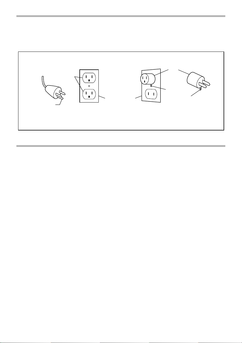
An adapter Fig. “B” and “C” is available for connecting Fig. “A” type plugs to two-prong
receptacles. The green-colored rigid ear, lug, etc., extending from the adapter must be connected to a permanent ground, such as a properly grounded outlet box.
GROUNDING METHODS
ADAPTER
GROUNDED
OUTLET
METAL
SCREW
TAB FOR
GROUNDING SCREW
GROUNDING
PIN
GROUNDED
OUTLET BOX
Fig. A Fig. B Fig. C
SPECIFIC SAFETY RULES
USB038-5
DO NOT let comfort or familiarity with product (gained from
repeated use) replace strict adherence to sander safety rules. If
you use this tool unsafely or incorrectly, you can suffer serious
personal injury.
1. Accessories must be rated for at least the
speed recommended on the tool warning
label.
Wheels and other accessories running
over rated speed can fly apart and cause
injury.
2. Hold tool by insulated gripping surfaces
when performing an operation where the
cutting tool may contact hidden wiring or
its own cord.
make exposed metal parts of the tool “live”
and shock the operator.
3. Always use safety glasses or goggles.
Ordinary eye or sun glasses are NOT
safety glasses.
4. Use only flanges specified for this tool.
Contact with a “live” wire will
5. NEVER use tool with wood cutting blades
or other sawblades. Such blades when
used on a sander frequently kick and
cause loss of control leading to personal
injury.
6. Hold the tool firmly.
7. Keep hands away from rotating parts.
8. Be careful not to damage the spindle, the
flange (especially the installing surface)
or the lock nut. Damage to these parts
could result in wheel breakage.
9. Make sure the abrasive disc or the wheel
is not contacting the workpiece before the
switch is turned on.
10. Watch out for flying sparks. Hold the tool
so that sparks fly away from you and other
persons or flammable materials.
5
Page 6

11. Do not leave the tool running. Operate the
tool only when hand-held.
12. Do not touch the workpiece immediately
after operation; it may be extremely hot
and could burn your skin.
13. Ventilate your work area adequately when
you perform sanding operations.
14. ALWAYS wear proper apparel including
long sleeve shirts, leather gloves and
shop aprons to protect skin from contact
with hot grindings.
15. Use of this tool to grind or sand some
products, paints and wood could expose
user to dust containing hazardous substances. Use appropriate respiratory protection.
IF USED AS A GRINDER
16. Always use proper guard with grinding
wheel.
ken wheel fragments.
17. When using depressed center grinding
wheels, be sure to use only fiberglassreinforced wheels.
18. Check the wheel carefully for cracks or
damage before operation. Replace
cracked or damaged wheel immediately.
Run the tool (with guard) at no load for
about a minute, holding tool away from
others. If wheel is flawed, it will likely separate during this test.
19. Before using the tool on an actual workpiece, let it run for a while. Watch for
vibration or wobbling that could indicate
poor installation or a poorly balanced
wheel.
20. Use the specified surface of the wheel to
perform the grinding.
SAVE THESE INSTRUCTIONS
A guard protects operator from bro-
WARNING:
MISUSE or failure to follow the safety rules stated in this
instruction manual may cause serious personal injury.
6
Page 7

FUNCTIONAL
DESCRIPTION
1
1. Shaft lock
12
1. Switch trigger
2. Lock button
CAUTION:
• Always be sure that the tool is switched off and
unplugged before adjusting or checking function on the
tool.
001028
Shaft lock
CAUTION:
• Never actuate the shaft lock when the spindle is moving.
The tool may be damaged.
Press the shaft lock to prevent spindle rotation when installing or removing accessories.
001043
Switch action
CAUTION:
• Before plugging in the tool, always check to see that the
switch trigger actuates properly and returns to the “OFF”
position when released.
• Switch can be locked in “ON” position for ease of
operator comfort during extended use. Apply caution
when locking tool in “ON” position and maintain firm
graspontool.
To start the tool, simply pull the switch trigger. Release the
switch trigger to stop. For continuous operation, pull the
switch trigger and then push in the lock button. To stop the
tool from the locked position, pull the switch trigger fully, then
release it.
7
Page 8

ASSEMBLY
1. Lock nut
2. Abrasive disc
3. Rubber pad
1
2
CAUTION:
• Always be sure that the tool is switched off and
unplugged before carrying out any work on the tool.
001059
Installing side grip (handle)
CAUTION:
• Always be sure that the side grip is installed securely
before operation.
Screw the side grip securely on the position of the tool as
shown in the figure.
001114
Installing or removing abrasive disc
1
(optional accessory)
2
NOTE:
3
• Use sander accessories specified in this manual. These
must be purchased separately.
Mount the rubber pad onto the spindle. Fit the disc on the
rubber pad and screw the lock nut onto the spindle.
001621
To tighten the lock nut, press the shaft lock firmly so that the
spindle cannot revolve, then use the lock nut wrench and
securely tighten clockwise.
To remove the disc, follow the installation procedure in
reverse.
1. Lock nut wrench
2. Shaft lock
8
IF USED AS A GRINDER
NOTE:
• Use grinder accessories specified in this manual. These
must be purchased by separate.
WARNING:
• Always use guard assembly or accessory kit, noted
below, for type 27 depressed center grinding wheel/
Multi-disc.
Page 9

001066
1
23
1. Wheel guard
2. Bearing box
3. Screw
001078
1
2
3
1. Lock nut
2. Depressed center grinding wheel/
Multi-disc
3. Inner flange
001091
1
2
• Guard assembly
Part No. 191214-3 ... For 180 mm (7”)
Part No. 191215-1 ... For 230 mm (9”)
Guard accessory kit
Part No. 191228-2 ... For 180 mm (7”)
Part No. 191231-3 ... For 230 mm (9”)
Installing or removing wheel guard
CAUTION:
• When using a depressed center grinding wheel/Multidisc, flex wheel or wire wheel brush, the wheel guard
must be fitted on the tool so that the closed side of the
guard always points toward the operator.
Mount the wheel guard with the protrusion on the wheel
guard band aligned with the groove on the bearing box. Be
sure to tighten both screws securely.
To remove wheel guard, follow the installation procedure in
reverse.
Installing or removing depressed center grinding
wheel/Multi-disc (optional accessory)
WARNING:
• Always use optional guard when depressed center
grinding wheel/Multi-disc is on tool. Wheel can shatter
during use and guard helps to reduce chances of
personal injury.
Mount the inner flange onto the spindle. Fit the wheel on the
inner flange and screw the lock nut onto the spindle.
To tighten the lock nut, press the shaft lock firmly so that the
spindle cannot revolve, then use the lock nut wrench and
securely tighten clockwise.
To remove the wheel, follow the installation procedure in
reverse.
1. Lock nut wrench
2. Shaft lock
9
Page 10

1. Lock nut
2. Flex wheel
3. Plastic pad
4. Inner flange
001103
1
2
3
4
Installing or removing flex wheel
(optional accessory)
WARNING:
• Always use specific guard when depressed center
grinding wheel/Multi-disc is on tool. Wheel can shatter
during use and guard helps to reduce chances of
personal injury.
Follow instructions for depressed center grinding wheel/
Multi-disc but also use plastic pad over wheel. See order of
assembly on accessories page in this manual.
OPERATION
AB
WARNING:
• It should never be necessary to force the tool. The
weight of the tool applies adequate pressure. Forcing
and excessive pressure could cause dangerous wheel
breakage.
• ALWAYS replace wheel if tool is dropped while grinding.
• NEVER bang or hit grinding disc or wheel onto work.
• Avoid bouncing and snagging the wheel, especially
when working corners, sharp edges etc. This can cause
loss of control and kickback.
• NEVER use tool with wood cutting blades and other
sawblades. Such blades when used on a grinder
frequently kick and cause loss of control leading to
personal injury.
CAUTION:
• After operation, always switch off the tool and wait until
the wheel has come to a complete stop before putting
the tool down.
001129
Grinding and sanding operation
ALWAYS hold the tool firmly with one hand on rear handle
and the other on the side handle. Turn the tool on and then
apply the wheel or disc to the workpiece.
In general, keep the edge of the wheel or disc at an angle of
15˚
about 15 degrees to the workpiece surface.
Duringthebreak-inperiodwithanewwheel,donotworkthe
grinder in the B direction or it will cut into the workpiece.
Once the edge of the wheel has been rounded off by use, the
wheel may be worked in both A and B direction.
10
Page 11

1. Wire cup brush
2. Urethane washer
1
1. Wire wheel brush
1
2
001143
Operation with wire cup brush
(optional accessory)
CAUTION:
• Check operation of brush by running tool with no load,
insuring that no one is in front of or in line with brush.
• Do not use brush that is damaged, or which is out of
balance. Use of damaged brush could increase potential
for injury from contact with broken brush wires.
Unplug tool and place it upside down allowing easy access
to spindle. Remove any accessories on spindle. Mount urethane washer then thread wire cup brush onto spindle and
tighten with supplied wrench. When using brush, avoid
applying too much pressure which causes over bending of
wires, leading to premature breakage.
NOTE:
• When using wire cup brush, mount urethane washer to
the spindle. It will make it easier to remove wire cup
brush.
001236
Operation with wire wheel brush
(optional accessory)
CAUTION:
• Check operation of wire wheel brush by running tool with
no load, insuring that no one is in front of or in line with
the wire wheel brush.
• Do not use wire wheel brush that is damaged, or which
is out of balance. Use of damaged wire wheel brush
could increase potential for injury from contact with
broken wires.
• ALWAYS use guard with wire wheel brushes, assuring
diameter of wheel fits inside guard. Wheel can shatter
during use and guard helps to reduce chances of
personal injury.
Unplug tool and place it upside down allowing easy access
to spindle. Remove any accessories on spindle. Thread wire
wheel brush onto spindle and tighten with the wrenches.
When using wire wheel brush, avoid applying too much pressure which causes over bending of wires, leading to premature breakage.
11
Page 12

MAINTENANCE
1
2
1. Exhaust vent
2. Inhalation vent
1
1. Limit mark
21
1. Brush holder cap
2. Screwdriver
CAUTION:
001171
• Always be sure that the tool is switched off and
unplugged before attempting to perform inspection or
maintenance.
The tool and its air vents have to be kept clean. Regularly
clean the tool’s air vents or whenever the vents start to
become obstructed.
001145
Replacing carbon brushes
Remove and check the carbon brushes regularly. Replace
when they wear down to the limit mark. Keep the carbon
brushes clean and free to slip in the holders. Both carbon
brushes should be replaced at the same time. Use only identical carbon brushes.
001156
Use a screwdriver to remove the brush holder caps. Take out
the worn carbon brushes, insert the new ones and secure
the brush holder caps.
To maintain product SAFETY and RELIABILITY, repairs, any
other maintenance or adjustment should be performed by
Makita Authorized or Factory Service Centers, always using
Makita replacement parts.
ACCESSORIES
12
CAUTION:
• These accessories or attachments are recommended for
use with your Makita tool specified in this manual. The
use of any other accessories or attachments might
present a risk of injury to persons. Only use accessory
or attachment for its stated purpose.
• If you decide to use your Makita sander with approved
accessories which you purchase from your Makita
distributor or factory service center, be sure to obtain
and use all necessary fasteners and guards as
Page 13

recommended in this manual. Your failure to do so could
result in personal injury to you and others.
If you need any assistance for more details regarding these
accessories, ask your local Makita service center.
001186
1
2
3
4
5
2
3
6
10
8
9
2
11
12
13
7
5
GA7911
1Grip36
2 Wheel guard
3 Inner flange 89
4 Depressed center grinding wheel/Multi-disc
5 Lock nut 5/8-45
6 Plastic pad
7 Flex wheel
8 Rubber pad 170
9 Abrasive disc
10 Sanding lock nut 5/8-48
11 Wire wheel brush
12 Urethane washer 14
13 Wire cup brush
- Lock nut wrench 28
- Accessory kit 7” or 9”
13
Page 14

Memo
14
Page 15

Memo
15
Page 16

Memo
16
Page 17

Cut
Makita U.S.A., Inc.
14930 Northam Street
La Mirada, CA 90638-5753
Fold
First-Class
Postage
Required
Post Office will
not deliver
without proper
postage.
17
Page 18

MAIL THIS PORTION
Your answer to the following questions are appreciated.
1. This product was purchased from:
Home Center
Hardware/Lumber Store
Tool Distributor
Industrial Supply
Construction Supply
2. Use of the product is intended for:
Construction Trade
Industrial Maintenance
Home Maintenance
Hobby
Other ( )
5. Any comments:
DATE PURCHASED MODEL NO.
MONTH DAY YEAR
INTL. LAST NAME / COMPANY NAME
Other ( )
3. How did you learn of about this product:
4. Most favored points are:
SERIAL NO.
Magazine
From Dealer
Newspaper
Store Display
Catalog
Design
Features
Size
Price
Makita Brand
Radio
Exhibition
From Friend
Previous Usage
Other ( )
Repair Service
Durability
Powe r
Other ( )
STATUS
Married
Single
SEX
MF
STREET ADRESS
CITY
AREA
S TATE
AGE:
BE SURE TO COMPLETE THE CUSTOMER’S PORTION OF THIS FORM AND RETAIN FOR YOUR RECORDS.
Paste Paste Paste Paste Paste Paste
18
Please return this portion by facsimile or mail.
Facsimile No: (714) 522-8133
ZIP CODE PHONE
Under 19 20-29 30-39 40-49 50-60 Over 60
CODE
Paste Paste Paste Paste Paste Paste Paste Paste
Paste Paste Paste Paste Paste Paste
Page 19

FACTORY SERVICE CENTERS
1-800-4-MAKITA
RETAIN THIS PORTION FOR YOUR RECORDS
ALABAMA
2365 Pelham Parkway
Pelham, AL 35124
(205) 620-1791
ARIZONA
3707 E. Broadway Rd., Ste.6
Phoenix, AZ 85040
(602) 437-2850
ARKANSAS
Shackleford Shopping Center
240 South Shackleford Rd.,
Ste. C
Little Rock, AR 72211
(501) 224-5733
CALIFORNIA
41850 Christy St.
Fremont, CA 94538-5107
(510) 657-9881
1421 N. Clovis Ave.,Ste. 112
Fresno, CA 93727
(559) 252-5166
14930 Northam St.
La Mirada, CA 90638-5753
(714) 522-8088
1970 Fulton Avenue
Sacramento, CA 95825
(916) 482-5197
1440 South “E” Street
San Bernardino, CA 92408
(909) 885-1289
7674 Clairemont Mesa Blvd.
San Diego, CA 92111
(858) 278-4471
1714 E.McFadden Ave.,Unit M
Santa Ana, CA 92705
(714) 667-5066
1565 Winchester B.
Campbell, CA 95008-0501
(408) 379-0377
16735 Saticoy St., Ste. 105
Van Nuys, CA 91406
(818) 782-2440
COLORADO
11839 E. 51st Ave.
Denver, CO 80239-2709
(303) 371-2850
CONNECTICUT
508 Spring St.
Windsor Locks, CT 06096
(860) 292-6405
FLORIDA
620 Douglas Ave.Suite 1302
Altamonte Springs, FL 32714
(407) 774-6000
750 East Sample Road
Pompano Beach, FL 33064
(954) 781-6333
Thompson Center Waters
5501 W.Waters Ave., Ste.406
Tampa,FL 33634
(813) 886-8292
GEORGIA
4680 River Green Parkway
Duluth, GA 30096-2566
(770) 476-8911
HAWAI I
4510 Salt Lake Blvd., Suite A7
Honolulu, HI 96818
(808) 847-0038
ILLINOIS
1450 Feehanville Dr.
Mt. Prospect, IL 60056-6011
(847) 297-3100
INDIANA
8403 Michigan Road, Unit 1
Indianapolis, IN 46268
(317) 334-9980
KANSAS
8819 W.95th St.
Overland Park, KS 66212
(913) 642-1111
KENTUCKY
1215 S. Hurstbourne Parkway
Louisville, KY 40222
(502) 326-3740
LOUSIANA
5626 Jefferson Hwy.
Harahan, LA 70123
(504) 733-4138
MARYLAND
7541 - 45 Ritchie Highway
Glen Burnie, MD 21061
(410) 590-0160
MASSACHUSETTS
232 Providence Hwy.
Westwood, MA 02090
(617) 461-9754
MICHIGAN
37454 Ann Arbor Trail
Livonia, MI 48150
(313) 432-1012
MINNESOTA
6427 Penn Ave.South
Richfield, MN 55423
(612) 869-5199
MISSOURI
9876 Watson Road
St. Louis, MO 63126-2221
(314) 909-9889
NEBRASKA
4129 S. 84th St.
Omaha, NE 68127
(402) 597-2925
NEVADA
3375 S. Decatur Blvd.
Suites. 22 - 24
Las Vegas,NV 89102
(702) 368-4277
NEW JERSEY
251 Herrod Blvd.
Dayton, NJ 08810-1539
(609) 655-1212
NEW MEXICO
5805 Menaul Blvd. NE
Albuquerque, NM 87110
(505) 881-4619
NEWYORK
4917 Genessee Street
Cheektowaga, NY 14225
(716) 685-9503
131-35 31st Ave.
Flushing, NY 11354
(718) 886-0971
NORTH CAROLINA
3501-G S.Tryon St.
Charlotte, NC 28217
(704) 527-0611
OHIO
6253 E. Main St.
Columbus, OH 43213
(614) 860-0222
6379 Pearl Road
Parma Heights, OH 44130
(440) 843-7555
1617 E. Kemper Rd.
Sharonville, OH 45246
(513) 771-0788
OKLAHOMA
552 E. Memorial Road
Oklahoma City, OK 73114
(405) 752-2655
OREGON
828 19th Avenue., N.W.
Portland, OR 97209
(503) 222-1823
PENNSYLVANIA
Springwater Plaza
364 Wilmington W.Chester
Pike
Glen Mills, PA19342
(610) 459-4122
6200 Babcock Blvd
Pittsburgh, PA15237
(412) 366-6363
PUERTO RICO
200 Guayama St.
Hato Rey,PR 00917
(787) 250-8776
TENNESSEE
4655 Nolensville Rd.
Nashville, TN 37211
(615) 331-9922
TEXAS
12801 Stemmons Fwy Ste. 809
Farmers Branch, TX 75234
(972) 243-1150
12701 Directors Dr.
Stafford, TX 77477-3701
(281) 565-8665
3453 IH-35 North, Ste. 101
San Antonio, TX 78219
(210) 228-0676
UTAH
145 E. 1300 S., Ste.101
Salt Lake City,UT 84115
(801) 359-3410
VIRGINIA
5760 Northampton Blvd,. Ste.
102
Virginia Beach, VA23455
(757) 460-0280
WASHINGTON
22220 84th Ave.So., Bldg. A
Kent, WA98032
(253) 395-8055
WISCONSIN
Lincoln Plaza Shopping Ctr.
2245 S. 108th St.West Allis, WI
53227
(414) 541-4776
CUSTOMER’S RECORD
When you need service: Send
complete tool (prepaid) to one
of the Makita Factory Service
Centers listed, or to an Authorized
Makita Service Center. Be sure
to attach a letter to the outside of
the carton detailing the problem
with your tool.
Date Purchased
Dealer’s Name & Address
Model No.
Serial No.
19
Page 20

WARNING
Some dust created by power sanding, sawing, grinding, drilling, and other
construction activities contains chemicals known to the State of California
to cause cancer, birth defects or other reproductive harm. Some examples
of these chemicals are:
• lead from lead-based paints,
• crystalline silica from bricks and cement and other masonry products, and
• arsenic and chromium from chemically-treated lumber.
Your risk from these exposures varies, depending on how often you do this
type of work. To reduce your exposure to these chemicals: work in a well
ventilated area, and work with approved safety equipment, such as those
dust masks that are specially designed to filter out microscopic particles.
MAKITA LIMITED ONE YEAR WARRANTY
Warranty Policy
Every Makita tool is thoroughly inspected and tested before leaving the factory. It is warranted to be free of
defects from workmanship and materials for the period of ONE YEAR from the date of original purchase.
Should any trouble develop during this one-year period, return the COMPLETE tool, freight prepaid, to one of
Makita's Factory or Authorized Service Centers. If inspection shows the trouble is caused by defective
workmanship or material, Makita will repair (or at our option, replace) without charge.
This Warranty does not apply where:
• repairs have been made or attempted by others:
• repairs are required because of normal wear and tear:
• The tool has been abused, misused or improperly maintained:
• alterations have been made to the tool.
IN NO EVENT SHALL MAKITA BE LIABLE FOR ANY INDIRECT, INCIDENTAL OR CONSEQUENTIAL
DAMAGES FROM THE SALE OR USE OF THE PRODUCT. THIS DISCLAIMER APPLIES BOTH DURING
AND AFTER THE TERM OF THIS WARRANTY.
MAKITA DISCLAIMS LIABILITY FOR ANY IMPLIED WARRANTIES, INCLUDING IMPLIED WARRANTIES OF
"MERCHANTABILITY" AND "FITNESS FOR A SPECIFIC PURPOSE," AFTER THE ONE-YEAR TERM OF
THIS WARRANTY.
This Warranty gives you specific legal rights, and you may also have other rights which vary form state to state.
Some states do not allow the exclusion or limitation of incidental or consequential damages, so the above
limitation or exclusion may not apply to you. Some states do not allow limitation on how long an implied
warranty lasts, so the above limitation may not apply to you.
883272H062
Makita Corporation
3-11-8, Sumiyoshi-cho,
Anjo, Aichi 446-8502 Japan
 Loading...