

Page 1
INSTRUCTION MANUAL
MANUEL D'INSTRUCTION
MANUAL DE INSTRUCCIONES
Angle Grinder
Meuleuse d’Angle
Esmeriladora Angular
GA4552
GA4552R
GA5052
GA5052R
DOUBLE INSULATION
DOUBLE ISOLATION
DOBLE AISLAMIENTO
Read before use.
À lire avant l’utilisation.
Lea antes de usar.
Page 2

ENGLISH (Original instructions)
SPECIFICATIONS
Model: GA4552 GA4552R GA5052 GA5052R
Wheel diameter 115 mm (4-1/2″) 125 mm (5″) * 125 mm (5″)
Max. wheel thickness 7.2 mm (9/32″)
Spindle thread 5/8″
Rated speed (n) 11,000 /min
Overall length 325 mm (12-3/4″)
Net weight 2.4 - 2.8 kg
Safety class
• Due to our continuing program of research and development, the specications herein are subject to change
without notice.
• Specications may dier from country to country.
• The weight may dier depending on the attachment(s). The lightest and heaviest combination, according to
EPTA-Procedure 01/2014, are shown in the table.
For US only
* If you install optional wheel guard indicated as 4-1/2″ on the tool, 115mm (4-1/2″) wheels can be used.
Power supply
The tool should be connected only to a power supply of
the same voltage as indicated on the nameplate, and
can only be operated on single-phase AC supply. They
are double-insulated and can, therefore, also be used
from sockets without earth wire.
SAFETY WARNINGS
General power tool safety warnings
WARNING: Read all safety warnings, instruc-
tions, illustrations and specications provided
with this power tool. Failure to follow all instructions
listed below may result in electric shock, re and/or
serious injury.
Save all warnings and instructions for future reference.
The term "power tool" in the warnings refers to your
mains-operated (corded) power tool or BATTERYoperated (cordless) power tool.
Work area safety
1. Keep work area clean and well lit. Cluttered or
dark areas invite accidents.
2. Do not operate power tools in explosive atmo-
spheres, such as in the presence of ammable
liquids, gases or dust. Power tools create sparks
which may ignite the dust or fumes.
3. Keep children and bystanders away while
operating a power tool. Distractions can cause
you to lose control.
(5.3 - 6.2 lbs)
Electrical Safety
1. Power tool plugs must match the outlet. Never
modify the plug in any way. Do not use any
adapter plugs with earthed (grounded) power
tools. Unmodied plugs and matching outlets will
reduce risk of electric shock.
2. Avoid body contact with earthed or grounded
surfaces, such as pipes, radiators, ranges and
refrigerators. There is an increased risk of elec-
tric shock if your body is earthed or grounded.
3. Do not expose power tools to rain or wet con-
ditions. Water entering a power tool will increase
the risk of electric shock.
4. Do not abuse the cord. Never use the cord for
carrying, pulling or unplugging the power tool.
Keep cord away from heat, oil, sharp edges
or moving parts. Damaged or entangled cords
increase the risk of electric shock.
5. When operating a power tool outdoors, use an
extension cord suitable for outdoor use. Use of
a cord suitable for outdoor use reduces the risk of
electric shock.
6. If operating a power tool in a damp location is
unavoidable, use a Residual Current Device
(RCD) protected supply. Use of an RCD reduces
the risk of electric shock.
7. Power tools can produce electromagnetic
elds (EMF) that are not harmful to the user.
However, users of pacemakers and other similar
medical devices should contact the maker of their
device and/or doctor for advice before operating
this power tool.
8. Do not touch the power plug with wet hands.
9. If the cord is damaged, have it replaced by the
manufacturer or his agent in order to avoid a
safety hazard.
2.5 - 2.8 kg (5.5 - 6.2 lbs)
/II
2 ENGLISH
Page 3

Personal Safety
1. Stay alert, watch what you are doing and use
common sense when operating a power tool.
Do not use a power tool while you are tired or
under the inuence of drugs, alcohol or medication. A moment of inattention while operating
power tools may result in serious personal injury.
2. Use personal protective equipment. Always
wear eye protection. Protective equipment such
as dust mask, non-skid safety shoes, hard hat, or
hearing protection used for appropriate conditions
will reduce personal injuries.
3. Prevent unintentional starting. Ensure the
switch is in the o-position before connecting
to power source and/or BATTERY pack, picking up or carrying the tool. Carrying power tools
with your nger on the switch or energising power
tools that have the switch on invites accidents.
4. Remove any adjusting key or wrench before
turning the power tool on. A wrench or a key left
attached to a rotating part of the power tool may
result in personal injury.
5. Do not overreach. Keep proper footing and
balance at all times. This enables better control
of the power tool in unexpected situations.
6. Dress properly. Do not wear loose clothing or
jewellery. Keep your hair, clothing and gloves
away from moving parts. Loose clothes, jewel-
lery or long hair can be caught in moving parts.
7. If devices are provided for the connection of
dust extraction and collection facilities, ensure
these are connected and properly used. Use of
dust collection can reduce dust-related hazards.
8. Do not let familiarity gained from frequent use
of tools allow you to become complacent and
ignore tool safety principles. A careless action
can cause severe injury within a fraction of a
second.
9. Always wear protective goggles to protect
your eyes from injury when using power tools.
The goggles must comply with ANSI Z87.1 in
the USA.
It is an employer's responsibility to enforce the
use of appropriate safety protective equipment
by the tool operators and by other persons in
the immediate working area.
Power tool use and care
1. Do not force the power tool. Use the correct
power tool for your application. The correct
power tool will do the job better and safer at the
rate for which it was designed.
2. Do not use the power tool if the switch does
not turn it on and o. Any power tool that cannot
be controlled with the switch is dangerous and
must be repaired.
3. Disconnect the plug from the power source
and/or remove the BATTERY pack, if detachable, from the power tool before making any
adjustments, changing accessories, or stor-
ing power tools. Such preventive safety measures reduce the risk of starting the power tool
accidentally.
4. Store idle power tools out of the reach of chil-
dren and do not allow persons unfamiliar with
the power tool or these instructions to operate
the power tool. Power tools are dangerous in the
hands of untrained users.
5. Maintain power tools and accessories. Check
for misalignment or binding of moving parts,
breakage of parts and any other condition that
may aect the power tool’s operation. If damaged, have the power tool repaired before use.
Many accidents are caused by poorly maintained
power tools.
6. Keep cutting tools sharp and clean. Properly
maintained cutting tools with sharp cutting edges
are less likely to bind and are easier to control.
7. Use the power tool, accessories and tool bits
etc. in accordance with these instructions, taking into account the working conditions and
the work to be performed. Use of the power tool
for operations dierent from those intended could
result in a hazardous situation.
8. Keep handles and grasping surfaces dry,
clean and free from oil and grease. Slippery
handles and grasping surfaces do not allow for
safe handling and control of the tool in unexpected
situations.
9. When using the tool, do not wear cloth work
gloves which may be entangled. The entanglement of cloth work gloves in the moving parts may
result in personal injury.
Service
1. Have your power tool serviced by a qualied
repair person using only identical replacement
parts. This will ensure that the safety of the power
tool is maintained.
2. Follow instruction for lubricating and chang-
ing accessories.
To reduce the risk of electric shock, this equipment has
a polarized plug (one blade is wider than the other).
This plug will t in a polarized outlet only one way. If the
plug does not t fully in the outlet, reverse the plug. If it
still does not t, contact a qualied electrician to install
the proper outlet. Do not change the plug in any way.
VOLTAGE WARNING: Before connecting the tool to a
power source (receptacle, outlet, etc.) be sure the voltage supplied is the same as that specied on the name-
plate of the tool. A power source with voltage greater
than that specied for the tool can result in SERIOUS
INJURY to the user- as well as damage to the tool. If in
doubt, DO NOT PLUG IN THE TOOL. Using a power
source with voltage less than the nameplate rating is
harmful to the motor.
USE PROPER EXTENSION CORD. Make sure your
extension cord is in good condition. When using an
extension cord, be sure to use one heavy enough to
carry the current your product will draw. An undersized
cord will cause a drop in line voltage resulting in loss of
power and overheating. Table 1 shows the correct size
to use depending on cord length and nameplate ampere
rating. If in doubt, use the next heavier gage. The
smaller the gage number, the heavier the cord.
3 ENGLISH
Page 4

Table 1: Minimum gage for cord
Ampere Rating Volts Total length of cord in feet
120V 25 ft. 50 ft. 100 ft. 150 ft.
220V - 240V 50 ft. 100 ft. 200 ft. 300 ft.
More Than Not More Than AWG
0 A 6 A – 18 16 16 14
6 A 10 A 18 16 14 12
10 A 12 A 16 16 14 12
12 A 16 A 14 12 Not Recommended
9.
Grinder safety warnings
Safety Warnings Common for Grinding, Sanding,
Wire Brushing, or Abrasive Cutting-O Operations:
1.
This power tool is intended to function as a
grinder, sander, wire brush or cut-o tool. Read
all safety warnings, instructions, illustrations
and specications provided with this power tool.
Failure to follow all instructions listed below may
result in electric shock, re and/or serious injury.
2.
Operations such as polishing are not recom-
mended to be performed with this power tool.
Operations for which the power tool was not designed
may create a hazard and cause personal injury.
3.
Do not use accessories which are not specically
designed and recommended by the tool manufac-
turer. Just because the accessory can be attached to
your power tool, it does not assure safe operation.
4. The rated speed of the accessory must be at
least equal to the maximum speed marked on
the power tool. Accessories running faster than
their rated speed can break and y apart.
5. The outside diameter and the thickness of your
accessory must be within the capacity rating
of your power tool. Incorrectly sized accessories
cannot be adequately guarded or controlled.
6.
Threaded mounting of accessories must match the
grinder spindle thread. For accessories mounted by
anges, the arbour hole of the accessory must t the
locating diameter of the ange. Accessories that do not
match the mounting hardware of the power tool will run out of
balance, vibrate excessively and may cause loss of control.
7.
Do not use a damaged accessory. Before each use
inspect the accessory such as abrasive wheels for chips
and cracks, backing pad for cracks, tear or excess wear,
wire brush for loose or cracked wires. If power tool or
accessory is dropped, inspect for damage or install an
undamaged accessory. After inspecting and installing an
accessory, position yourself and bystanders away from
the plane of the rotating accessory and run the power
tool at maximum no-load speed for one minute. Damaged
accessories will normally break apart during this test time.
8.
Wear personal protective equipment.
Depending on application, use face shield,
safety goggles or safety glasses. As appropri-
ate, wear dust mask, hearing protectors, gloves
and workshop apron capable of stopping small
abrasive or workpiece fragments. The eye pro-
tection must be capable of stopping ying debris
generated by various operations. The dust mask
or respirator must be capable of ltrating particles
generated by your operation. Prolonged exposure
to high intensity noise may cause hearing loss.
Keep bystanders a safe distance away from work
area. Anyone entering the work area must wear
personal protective equipment. Fragments of
workpiece or of a broken accessory may y away and
cause injury beyond immediate area of operation.
10.
Hold the power tool by insulated gripping surfaces only, when performing an operation where
the cutting accessory may contact hidden wiring
or its own cord. Cutting accessory contacting a "live"
wire may make exposed metal parts of the power tool
“live” and could give the operator an electric shock.
11.
Position the cord clear of the spinning accessory. If
you lose control, the cord may be cut or snagged and your
hand or arm may be pulled into the spinning accessory.
12. Never lay the power tool down until the acces-
sory has come to a complete stop. The spinning
accessory may grab the surface and pull the
power tool out of your control.
13.
Do not run the power tool while carrying it at your
side. Accidental contact with the spinning accessory could
snag your clothing, pulling the accessory into your body.
14. Regularly clean the power tool’s air vents. The
motor’s fan will draw the dust inside the housing
and excessive accumulation of powdered metal
may cause electrical hazards.
15. Do not operate the power tool near ammable
materials. Sparks could ignite these materials.
16. Do not use accessories that require liquid
coolants. Using water or other liquid coolants
may result in electrocution or shock.
Kickback and Related Warnings
Kickback is a sudden reaction to a pinched or snagged rotating
wheel, backing pad, brush or any other accessory. Pinching or
snagging causes rapid stalling of the rotating accessory which in
turn causes the uncontrolled power tool to be forced in the direc
tion opposite of the accessory’s rotation at the point of the binding.
For example, if an abrasive wheel is snagged or pinched
by the workpiece, the edge of the wheel that is entering
into the pinch point can dig into the surface of the material
causing the wheel to climb out or kick out. The wheel may
either jump toward or away from the operator, depending on
direction of the wheel’s movement at the point of pinching.
Abrasive wheels may also break under these conditions.
Kickback is the result of power tool misuse and/or
incorrect operating procedures or conditions and can be
avoided by taking proper precautions as given below.
1. Maintain a rm grip on the power tool and
position your body and arm to allow you to
resist kickback forces. Always use auxiliary
handle, if provided, for maximum control over
kickback or torque reaction during start-up.
The operator can control torque reactions or kickback forces, if proper precautions are taken.
4 ENGLISH
-
Page 5

2. Never place your hand near the rotating acces-
sory. Accessory may kickback over your hand.
3. Do not position your body in the area where
power tool will move if kickback occurs.
Kickback will propel the tool in direction opposite
to the wheel’s movement at the point of snagging.
4. Use special care when working corners, sharp
edges etc. Avoid bouncing and snagging the
accessory. Corners, sharp edges or bouncing
have a tendency to snag the rotating accessory
and cause loss of control or kickback.
5. Do not attach a saw chain woodcarving blade
or toothed saw blade. Such blades create frequent kickback and loss of control.
Safety Warnings Specic for Grinding and Abrasive
Cutting-O Operations:
1. Use only wheel types that are recommended
for your power tool and the specic guard
designed for the selected wheel. Wheels for
which the power tool was not designed cannot be
adequately guarded and are unsafe.
2.
The grinding surface of centre depressed wheels
must be mounted below the plane of the guard lip.
An improperly mounted wheel that projects through the
plane of the guard lip cannot be adequately protected.
3.
The guard must be securely attached to the
power tool and positioned for maximum safety,
so the least amount of wheel is exposed towards
the operator. The guard helps to protect the opera-
tor from broken wheel fragments, accidental contact
with wheel and sparks that could ignite clothing.
4.
Wheels must be used only for recommended
applications. For example: do not grind with the
side of cut-o wheel. Abrasive cut-o wheels are
intended for peripheral grinding, side forces applied
to these wheels may cause them to shatter.
5.
Always use undamaged wheel anges that are of
correct size and shape for your selected wheel.
Proper wheel anges support the wheel thus reducing
the possibility of wheel breakage. Flanges for cut-o
wheels may be dierent from grinding wheel anges.
6.
Do not use worn down wheels from larger power
tools. Wheel intended for larger power tool is not suitable
for the higher speed of a smaller tool and may burst.
Additional Safety Warnings Specic for Abrasive
Cutting-O Operations:
1. Do not “jam“ the cut-o wheel or apply excessive pressure. Do not attempt to make an
excessive depth of cut. Overstressing the wheel
increases the loading and susceptibility to twisting
or binding of the wheel in the cut and the possibility of kickback or wheel breakage.
2. Do not position your body in line with and
behind the rotating wheel. When the wheel, at
the point of operation, is moving away from your
body, the possible kickback may propel the spinning wheel and the power tool directly at you.
3.
When wheel is binding or when interrupting a cut
for any reason, switch o the power tool and hold
the power tool motionless until the wheel comes to
a complete stop. Never attempt to remove the cuto wheel from the cut while the wheel is in motion
otherwise kickback may occur. Investigate and take
corrective action to eliminate the cause of wheel binding.
4. Do not restart the cutting operation in the
workpiece. Let the wheel reach full speed and
carefully re-enter the cut. The wheel may bind,
walk up or kickback if the power tool is restarted in
the workpiece.
5. Support panels or any oversized workpiece to
minimize the risk of wheel pinching and kick-
back. Large workpieces tend to sag under their
own weight. Supports must be placed under the
workpiece near the line of cut and near the edge
of the workpiece on both sides of the wheel.
6. Use extra caution when making a “pocket cut”
into existing walls or other blind areas. The
protruding wheel may cut gas or water pipes, elec-
trical wiring or objects that can cause kickback.
Safety Warnings Specic for Sanding Operations:
1. Do not use excessively oversized sanding
disc paper. Follow manufacturers recommendations, when selecting sanding paper. Larger
sanding paper extending beyond the sanding
pad presents a laceration hazard and may cause
snagging, tearing of the disc or kickback.
Safety Warnings Specic for Wire Brushing
Operations:
1. Be aware that wire bristles are thrown by the
brush even during ordinary operation. Do not
overstress the wires by applying excessive
load to the brush. The wire bristles can easily
penetrate light clothing and/or skin.
2. If the use of a guard is recommended for wire
brushing, do not allow any interference of the
wire wheel or brush with the guard. Wire wheel
or brush may expand in diameter due to work load
and centrifugal forces.
Additional Safety Warnings:
1.
When using depressed centre grinding wheels,
be sure to use only berglass-reinforced wheels.
2. NEVER USE Stone Cup type wheels with this
grinder. This grinder is not designed for these
types of wheels and the use of such a product
may result in serious personal injury.
3. Be careful not to damage the spindle, the
ange (especially the installing surface) or the
lock nut. Damage to these parts could result in
wheel breakage.
4. Make sure the wheel is not contacting the
workpiece before the switch is turned on.
5. Before using the tool on an actual workpiece,
let it run for a while. Watch for vibration or
wobbling that could indicate poor installation
or a poorly balanced wheel.
6. Use the specied surface of the wheel to per-
form the grinding.
7. Do not leave the tool running. Operate the tool
only when hand-held.
8. Do not touch the workpiece immediately after
operation; it may be extremely hot and could
burn your skin.
9. Do not touch accessories immediately after
operation; it may be extremely hot and could
burn your skin.
10. Observe the instructions of the manufacturer
for correct mounting and use of wheels.
Handle and store wheels with care.
5 ENGLISH
Page 6

11. Do not use separate reducing bushings or
adaptors to adapt large hole abrasive wheels.
12. Use only anges specied for this tool.
13. For tools intended to be tted with threaded
hole wheel, ensure that the thread in the wheel
is long enough to accept the spindle length.
14. Check that the workpiece is properly
supported.
15. Pay attention that the wheel continues to
rotate after the tool is switched o.
16. If working place is extremely hot and humid,
or badly polluted by conductive dust, use a
short-circuit breaker (30 mA) to assure opera-
tor safety.
17. Do not use the tool on any materials contain-
ing asbestos.
18. When use cut-o wheel, always work with
the dust collecting wheel guard required by
domestic regulation.
19. Cutting discs must not be subjected to any
lateral pressure.
20. Do not use cloth work gloves during operation.
Fibers from cloth gloves may enter the tool, which
causes tool breakage.
SAVE THESE INSTRUCTIONS.
WARNING: DO NOT let comfort or familiarity
with product (gained from repeated use) replace
strict adherence to safety rules for the subject
product. MISUSE or failure to follow the safety
rules stated in this instruction manual may cause
serious personal injury.
Symbols
The followings show the symbols used for tool.
volts
amperes
hertz
alternating current
FUNCTIONAL
DESCRIPTION
CAUTION: Always be sure that the tool is
switched o and unplugged before adjusting or
checking function on the tool.
Shaft lock
Press the shaft lock to prevent spindle rotation when
installing or removing accessories.
1
► 1. Shaft lock
NOTICE: Never actuate the shaft lock when the
spindle is moving. The tool may be damaged.
Switch action
CAUTION: Before plugging in the tool, always
check to see that the switch trigger actuates
properly and returns to the "OFF" position when
released.
CAUTION: Do not pull the switch lever forc-
ibly without pressing the lock-o button. The
switch may break.
To prevent the switch lever from accidentally pulled, a
lock-o lever is provided. To start the tool, pull the locko lever toward the operator, and then pull the switch
lever. Release the switch lever to stop.
alternating or direct current
rated speed
Class II Construction
revolutions or reciprocation per minute
diameter
2
1
► 1. Lock-o lever 2. Switch lever
6 ENGLISH
Page 7
Unintentional restart proof
Only for model GA4552R / GA5052R
The tool does not start while pulling the switch lever
even when the tool is plugged. To start the tool, rst
release the switch lever. Then pull the lock-o lever, and
pull the switch lever.
NOTE: Wait more than one second before restarting
the tool when unintentional restart proof functions.
Soft start feature
Only for model GA4552R / GA5052R
Soft start feature reduces starting reaction.
For depressed center wheel, ap disc,
ex wheel, wire wheel brush / abrasive
cut-o wheel, diamond wheel
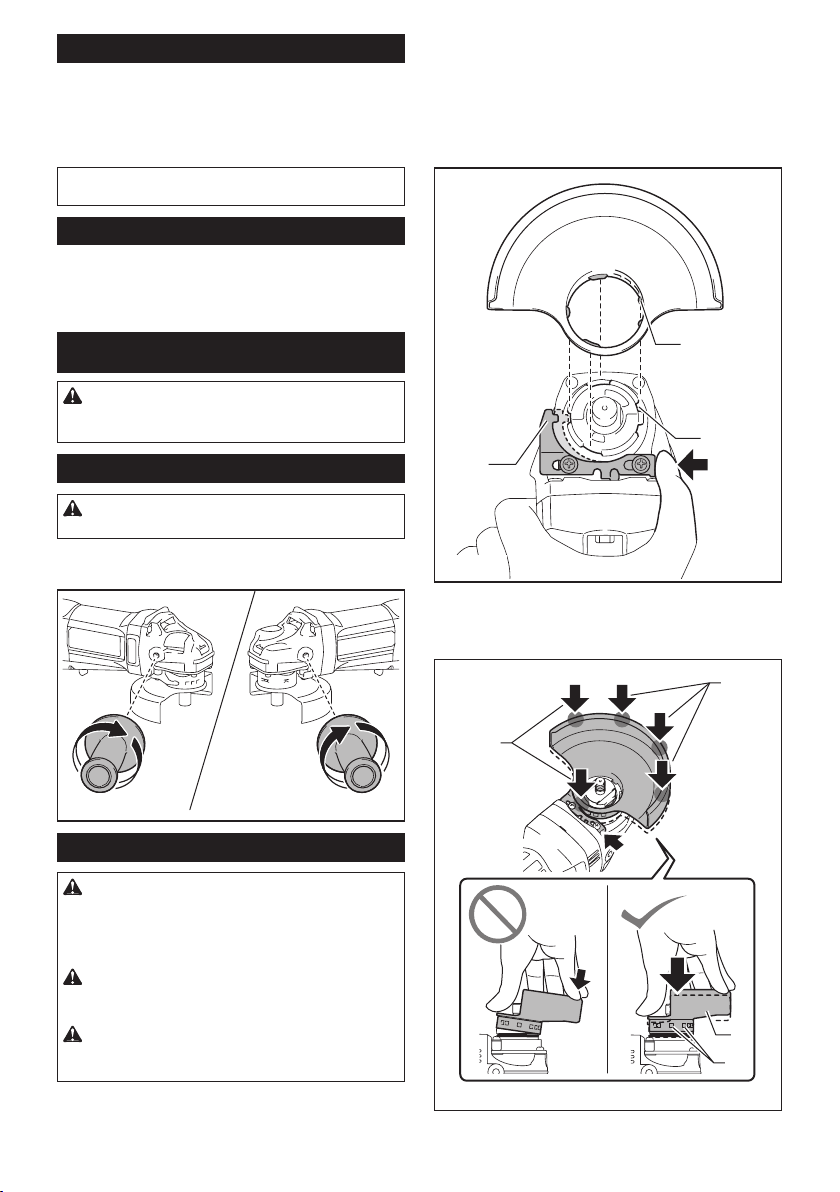
1. While pushing the lock lever, mount the wheel
guard with the protrusions on the wheel guard aligned
with the notches on the bearing box.
ASSEMBLY
CAUTION: Always be sure that the tool is
switched o and unplugged before carrying out
any work on the tool.
Installing side grip (handle)
CAUTION: Always be sure that the side grip is
installed securely before operation.
Screw the side grip securely on the position of the tool
as shown in the gure.
Installing or removing wheel guard
WARNING: When using a depressed center
wheel, ap disc, ex wheel or wire wheel brush,
the wheel guard must be tted on the tool so that
the closed side of the guard always points toward
the operator.
WARNING: Make sure that the wheel guard is
securely locked by the lock lever with one of the
holes on the wheel guard.
WARNING: When using an abrasive cut-o
/ diamond wheel, be sure to use only the special
wheel guard designed for use with cut-o wheels.
3
2
1
► 1. Lock lever 2. Notch 3. Protrusion
2.
While pushing the lock lever toward A, hold down
the portions B of the wheel guard as shown in the gure.
B
B
A
1
2
► 1. Wheel guard 2. Hole
7 ENGLISH
Page 8
NOTE: Push down the wheel guard straight.
Otherwise, you cannot secure the wheel guard.
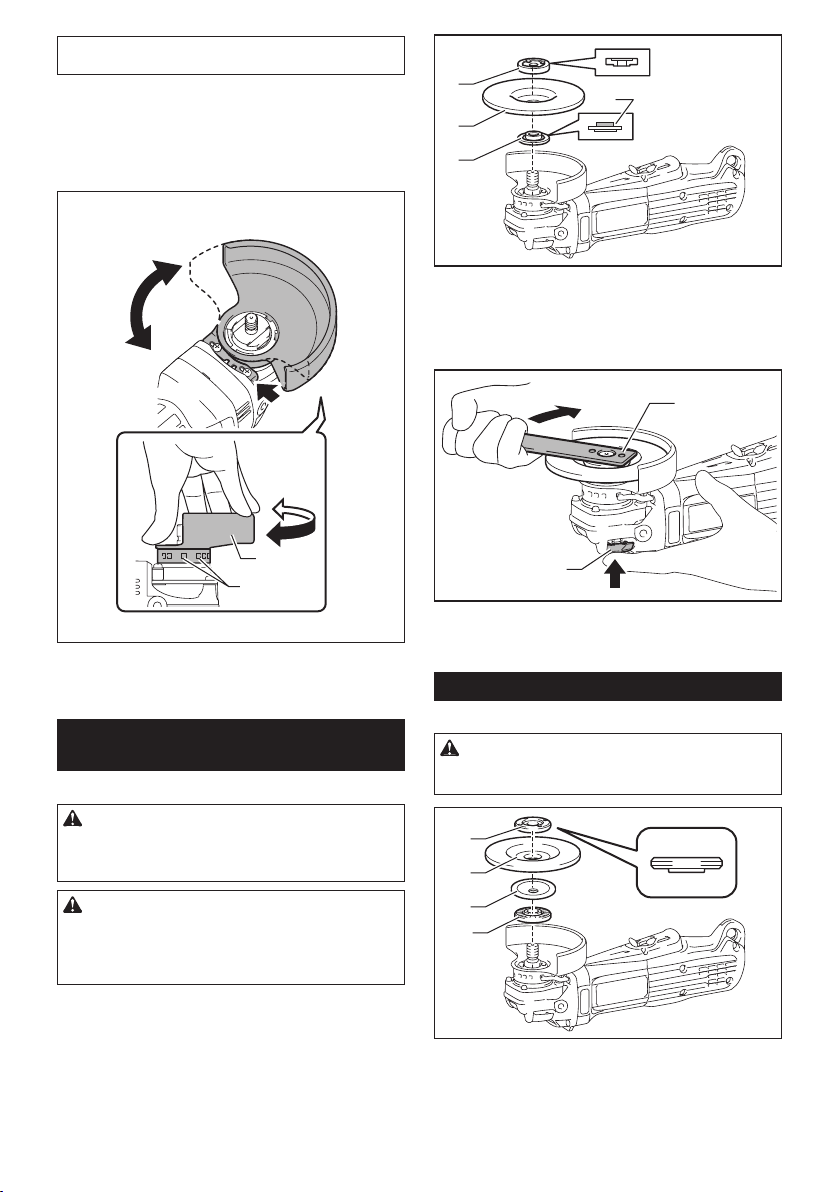
3. While pushing the lock lever, rotate the wheel
guard toward C, and then, change the angle of the
wheel guard according to the work so that the operator
can be protected. Align the lock lever with one of the
holes in the wheel guard, and then release the lock
lever to lock the wheel guard.
C
1
4
2
3
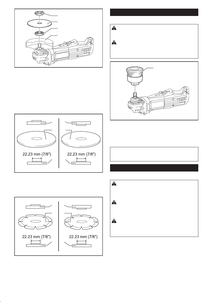
► 1. Lock nut 2. Depressed center wheel 3. Inner
ange 4. Mounting part
To tighten the lock nut, press the shaft lock rmly so
that the spindle cannot revolve, then use the lock nut
wrench and securely tighten clockwise.
A
C
1
2
► 1. Wheel guard 2. Hole
To remove wheel guard, follow the installation procedure in reverse.
Installing or removing depressed
center wheel or ap disc
Optional accessory
WARNING: When using a depressed center
wheel or ap disc, the wheel guard must be tted
on the tool so that the closed side of the guard
always points toward the operator.
CAUTION: Make sure that the mounting part
of the inner ange ts into the inner diameter of
the depressed center wheel / ap disc perfectly.
Mounting the inner ange on the wrong side may
result in the dangerous vibration.
Mount the inner ange onto the spindle.
Make sure to t the dented part of the inner ange onto
the straight part at the bottom of the spindle.
Fit the depressed center wheel / ap disc on the inner
ange and screw the lock nut onto the spindle.
1
2
► 1. Lock nut wrench 2. Shaft lock
To remove the wheel, follow the installation procedure
in reverse.
Installing or removing ex wheel
Optional accessory
WARNING: Always use supplied guard when
ex wheel is on tool. Wheel can shatter during use
and guard helps to reduce chances of personal injury.
1
2
3
4
► 1. Lock nut 2. Flex wheel 3. Back up pad 4. Inner
ange
Follow instructions for depressed center wheel but also
use back up pad over wheel. See order of assembly on
accessories page in this manual.
8 ENGLISH
Page 9
Installing or removing abrasive disc
Optional accessory
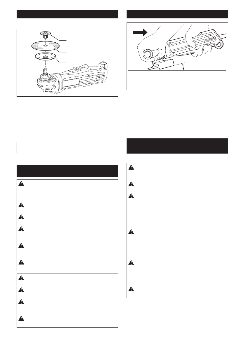
1
2
3
Operation with wheel/disc
15°
► 1. Sanding lock nut 2. Abrasive disc 3. Rubber pad
1. Mount the rubber pad onto the spindle.
2. Fit the disc on the rubber pad and screw the sand-
ing lock nut onto the spindle.
Hold the spindle with the shaft lock, and securely tighten
3.
the sanding lock nut clockwise with the lock nut wrench.
To remove the disc, follow the installation procedure in reverse.
NOTE: Use sander accessories specied in this man-
ual. These must be purchased separately.
OPERATION
WARNING: It should never be necessary to
force the tool. The weight of the tool applies adequate pressure. Forcing and excessive pressure
could cause dangerous wheel breakage.
WARNING: ALWAYS replace wheel if tool is
dropped while grinding.
WARNING: NEVER bang or hit grinding disc
or wheel onto work.
WARNING:
wheel, especially when working corners, sharp
edges etc. This can cause loss of control and kickback.
WARNING:
and other saw blades. Such blades when used on a grinder fre-
quently kick and cause loss of control leading to personal injury.
WARNING:
result in wheel explosion and serious personal injury.
CAUTION:
tact with the workpiece, it may cause an injury to operator.
CAUTION: Always wear safety goggles or a
face shield during operation.
CAUTION: After operation, always switch o
the tool and wait until the wheel has come to a
complete stop before putting the tool down.
CAUTION:
hand on housing and the other on the side grip (handle).
Avoid bouncing and snagging the
NEVER use tool with wood cutting blades
Continued use of a worn-out wheel may
Never switch on the tool when it is in con-
ALWAYS hold the tool rmly with one
Turn the tool on and then apply the wheel or disc to the
workpiece.
In general, keep the edge of the wheel or disc at an
angle of about 15° to the workpiece surface.
During the break-in period with a new wheel, do not
work the grinder in forward direction or it may cut into
the workpiece. Once the edge of the wheel has been
rounded o by use, the wheel may be worked in both
forward and backward direction.
Operation with abrasive cut-o /
diamond wheel
Optional accessory
WARNING: When using an abrasive cut-o
/ diamond wheel, be sure to use only the special
wheel guard designed for use with cut-o wheels.
WARNING: NEVER use cut-o wheel for side
grinding.
WARNING: Do not "jam" the wheel or apply
excessive pressure. Do not attempt to make an
excessive depth of cut. Overstressing the wheel
increases the loading and susceptibility to twisting
or binding of the wheel in the cut and the possibility
of kickback, wheel breakage and overheating of the
motor may occur.
WARNING: Do not start the cutting operation
in the workpiece. Let the wheel reach full speed
and carefully enter into the cut moving the tool
forward over the workpiece surface. The wheel
may bind, walk up or kickback if the power tool is
started in the workpiece.
WARNING: During cutting operations, never
change the angle of the wheel. Placing side pres-
sure on the cut-o wheel (as in grinding) will cause
the wheel to crack and break, causing serious per-
sonal injury.
WARNING: A diamond wheel shall be oper-
ated perpendicular to the material being cut.
9 ENGLISH
Page 10
1
2
3
4
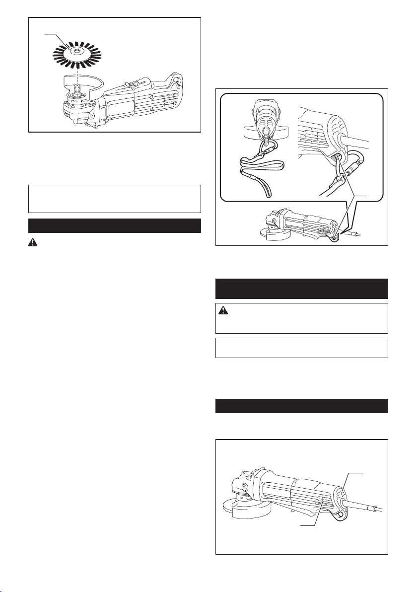
Operation with wire cup brush
Optional accessory
CAUTION: Check operation of brush by run-
ning tool with no load, insuring that no one is in
front of or in line with brush.
CAUTION: Do not use brush that is damaged,
or which is out of balance. Use of damaged brush
could increase potential for injury from contact with
broken brush wires.
► 1. Lock nut 2. Abrasive cut-o wheel / diamond
wheel 3. Inner ange 4. Wheel guard for abrasive
cut-o wheel / diamond wheel
As for the installation, follow the instructions for
depressed center wheel.
The direction for mounting the lock nut and the
inner ange varies by wheel type and thickness.
Refer to the following gures.
When installing the abrasive cut-o wheel:
11
23
44
► 1. Lock nut 2. Abrasive cut-o wheel (Thinner than 4
mm (5/32")) 3. Abrasive cut-o wheel (4 mm (5/32")
or thicker) 4. Inner ange
When installing the diamond wheel:
11
23
44
1
► 1. Wire cup brush
Unplug tool and place it upside down allowing easy
access to spindle.
Remove any accessories on spindle. Thread wire cup
brush onto spindle and tighten with supplied wrench.
NOTICE: Avoid applying too much pressure
which causes over bending of wires when using
brush. It may lead to premature breakage.
Operation with wire wheel brush
Optional accessory
CAUTION: Check operation of wire wheel
brush by running tool with no load, insuring that
no one is in front of or in line with the wire wheel
brush.
CAUTION: Do not use wire wheel brush that
is damaged, or which is out of balance. Use of
damaged wire wheel brush could increase potential
for injury from contact with broken wires.
CAUTION: ALWAYS use guard with wire
wheel brushes, assuring diameter of wheel ts
inside guard. Wheel can shatter during use and
guard helps to reduce chances of personal injury.
► 1. Lock nut 2. Diamond wheel (Thinner than 4 mm
(5/32″)) 3. Diamond wheel (4 mm (5/32″) or thicker)
4. Inner ange
10 ENGLISH
Page 11
1
► 1. Wire wheel brush
Unplug tool and place it upside down allowing easy
access to spindle.
Remove any accessories on spindle. Thread wire wheel
brush onto spindle and tighten with the wrenches.
NOTICE:
which causes over bending of wires when using
wire wheel brush. It may lead to premature breakage.
Avoid applying too much pressure
Lanyard (tether strap) connection
15.
Use a locking carabiner (multi-action and screw gate
type). Do not use single action spring clip carabiners.
16.
In the event the tool is dropped, it must be tagged
and removed from service, and should be inspected
by a Makita Factory or Authorized Service Center.
17.
Only attach the lanyard with a locking cara-
biner. Do not attach the lanyard by looping or
knotting the lanyard. Do not use ropes or cords.
1
Safety warnings specic for use at height
Read all safety warnings and instructions. Failure to follow
the warnings and instructions may result in serious injury.
1.
Always keep the tool tethered when working "at
height". Maximum lanyard length is 2 m (6.5 ft).
The maximum permissible fall height for lanyard (tether strap) must not exceed 2 m (6.5 ft).
2. Use only with lanyards appropriate for this tool
type and rated for at least 4.0 kg (8.8 lbs).
3.
Do not anchor the tool lanyard to anything on your body or
on movable components. Anchor the tool lanyard to a rigid
structure that can withstand the forces of a dropped tool.
4. Make sure the lanyard is properly secured at
each end prior to use.
5. Inspect the tool and lanyard before each use
for damage and proper function (including
fabric and stitching). Do not use if damaged
or not functioning properly. The tool must be
repaired especially when a crack or a red line
appears around the hole for the lanyard.
6. Do not wrap lanyards around or allow them to
come in contact with sharp or rough edges.
7.
Fasten the other end of the lanyard outside the
working area so that a falling tool is held securely.
8.
Attach the lanyard so that the tool will move away
from the operator if it falls. Dropped tools will swing on
the lanyard, which could cause injury or loss of balance.
9.
Do not use near moving parts or running machinery.
Failure to do so may result in a crush or entanglement hazard.
10. Do not carry the tool by the attachment device
or the lanyard.
11. Only transfer the tool between your hands
while you are properly balanced.
12.
Do not attach lanyards to the tool in a way that keeps
guards, switches or lock-os from operating properly.
13. Avoid getting tangled in the lanyard.
14.
Keep lanyard away from the cutting area of the tool.
► 1. Hole for lanyard (tether strap)
MAINTENANCE
CAUTION: Always be sure that the tool is
switched o and unplugged before attempting to
perform inspection or maintenance.
NOTICE:
or the like. Discoloration, deformation or cracks may result.
To maintain product SAFETY and RELIABILITY,
repairs, any other maintenance or adjustment should
be performed by Makita Authorized or Factory Service
Centers, always using Makita replacement parts.
Air vent cleaning
The tool and its air vents have to be kept clean. Regularly clean the
tool's air vents or whenever the vents start to become obstructed.
► 1. Exhaust vent 2. Inhalation vent
11 ENGLISH
Never use gasoline, benzine, thinner, alcohol
1
2
Page 12
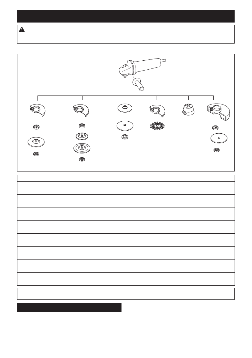
OPTIONAL ACCESSORIES
CAUTION: These accessories or attachments are recommended for use with your Makita tool spec-
ied in this manual. The use of any other accessories or attachments might present a risk of injury to persons.
Only use accessory or attachment for its stated purpose.
If you need any assistance for more details regarding these accessories, ask your local Makita Service Center.
1
2
3
22
3
6
10
8
9
11
12
4
7
5
NOTE: Some items in the list may be included in the tool package as standard accessories. They may dier from
country to country.
MAKITA LIMITED WARRANTY
Please refer to the annexed warranty sheet for the
most current warranty terms applicable to this product.
If annexed warranty sheet is not available, refer to the
warranty details set forth at below website for your
respective country.
5
- 115 mm (4-1/2″) model 125 mm (5″) model
1 Side grip
2 Wheel Guard (for grinding wheel)
3 Inner ange
4 Depressed center wheel / Flap disc
5 Lock nut
6 Back up pad
7 Flex wheel
8 Rubber pad 100 Rubber pad 115
9 Abrasive disc
10 Sanding lock nut
11 Wire wheel brush
12 Wire cup brush
13 Wheel Guard (for cut-o wheel)
14 Abrasive cut-o wheel / Diamond wheel
- Lock nut wrench
- Dust cover attachment
United States of America: www.makitatools.com
Canada: www.makita.ca
Other countries: www.makita.com
12 ENGLISH
13
3
14
5
Page 13

FRANÇAIS (Mode d’emploi original)
SPÉCIFICATIONS
Modèle : GA4552 GA4552R GA5052 GA5052R
Diamètre de la meule 115 mm (4-1/2″) 125 mm (5″) * 125 mm (5″)
Épaisseur de meule max. 7,2 mm (9/32″)
Filetage de l’arbre 5/8″
Vitesse nominale (n) 11 000 /min
Longueur totale 325 mm (12-3/4″)
Poids net 2,4 - 2,8 kg
Classe de sécurité
• Étant donné l’évolution constante de notre programme de recherche et de développement, les spécications
contenues dans ce manuel sont sujettes à modication sans préavis.
• Les spécications peuvent varier suivant les pays.
• Le poids peut varier suivant les accessoires. La plus légère et la plus lourde des combinaisons, selon la procédure EPTA 01/2014, sont indiquées dans le tableau.
Pour les États-Unis uniquement
* Si vous installez sur l’outil un protecteur de meule 4-1/2″ en option, les meules de 115 mm (4-1/2″) pourront être utilisées.
Alimentation
L’outil ne doit être branché que sur une source d’alimentation
de la même tension que celle indiquée sur la plaque signalétique, et il ne peut être utilisé qu’avec un courant alternatif
monophasé. Dotés d’une double isolation, ils peuvent aussi
être utilisés sur des prises sans l de mise à la terre.
CONSIGNES DE
SÉCURITÉ
Consignes de sécurité générales
pour outils électriques
MISE EN GARDE : Veuillez lire toutes les
mises en garde, instructions, illustrations et
spécications qui accompagnent cet outil électrique. Ne pas suivre toutes les instructions de la liste
ci-dessous peut entraîner une décharge électrique,
un incendie et/ou une grave blessure.
Conservez toutes les mises en
garde et instructions pour référence future.
Le terme « outil électrique » qui gure dans les avertissements fait référence à un outil électrique branché sur
une prise de courant (par un cordon d’alimentation) ou
alimenté par batterie (sans l).
Sécurité de la zone de travail
1.
Maintenez la zone de travail propre et bien éclairée. Les zones de travail encombrées ou sombres
ouvrent toute grande la porte aux accidents.
(5,3 - 6,2 lbs)
2.
N’utilisez pas les outils électriques dans les
atmosphères explosives, telles que celles où sont
présents des liquides, gaz ou poussières inammables. Les outils électriques génèrent des étincelles
qui peuvent allumer les poussières ou les vapeurs.
3. Gardez les enfants et personnes présentes
à l’écart pendant l’utilisation d’un outil électrique. Toute distraction peut vous faire perdre la
maîtrise de l’outil.
Sécurité en matière d’électricité
1.
Les ches d’outil électrique doivent correspondre à la prise de courant. Ne modiez jamais
la che, de quelque façon que ce soit. N’utilisez
aucune che d’adaptation avec les outils élec-
triques mis à la terre (à la masse). Les ches non
modiées et les prises de courant correspondantes
réduisent le risque de décharge électrique.
2. Évitez tout contact avec les surfaces mises
à la terre ou à la masse, telles que celles des
tuyaux, radiateurs, cuisinières et réfrigérateurs. Le risque de décharge électrique augmente
si votre corps est mis à la terre ou à la masse.
3. N’exposez pas les outils électriques à la pluie
ou à des surfaces mouillées. La pénétration
d’eau dans un outil électrique augmente le risque
de décharge électrique.
4. Ne maltraitez pas le cordon. N’utilisez jamais
le cordon pour transporter, tirer sur ou débrancher l’outil électrique. Gardez le cordon à
l’écart de la chaleur, de l’huile, des bords
tranchants ou des pièces en mouvement. Les
cordons endommagés ou enchevêtrés augmentent le risque de décharge électrique.
5. Lorsque vous utilisez un outil électrique à l’ex-
térieur, faites-le avec un cordon prolongateur
conçu pour l’usage extérieur. Utiliser un cordon
conçu pour l’usage extérieur réduit le risque de
décharge électrique.
2,5 - 2,8 kg (5,5 - 6,2 lbs)
/II
13 FRANÇAIS
Page 14

6. Si l’utilisation d’un outil électrique dans un
emplacement humide est inévitable, utilisez
une source d’alimentation protégée par un
disjoncteur diérentiel de fuite à la terre
(DDFT). Utiliser un DDFT réduit le risque de
décharge électrique.
7. Les outils électriques peuvent produire des
champs électromagnétiques (CEM) qui ne sont
pas préjudiciables à l’utilisateur. Les utilisateurs de stimulateur cardiaque ou autres appareils
médicaux similaires doivent toutefois demander
conseil au fabricant et/ou à leur médecin avant
d’utiliser cet outil électrique.
8. Ne touchez pas la che d’alimentation avec les
mains mouillées.
9. Si le cordon est endommagé, faites-le rempla-
cer par le fabricant ou son représentant, pour
éviter les risques d’accident.
Sécurité personnelle
1. Restez vigilant, attentif à vos gestes et faites
preuve de bon sens pendant l’utilisation
d’un outil électrique. N’utilisez pas un outil
électrique lorsque vous êtes fatigué ou sous
l’inuence d’une drogue, de l’alcool ou d’un
médicament. Tout moment d’inattention pendant
l’utilisation des outils électriques peut entraîner
une grave blessure.
2. Utilisez l’équipement de protection individuel.
Portez toujours un protecteur pour la vue.
Utilisé dans les conditions adéquates, l’équipement de protection - masque antipoussière,
chaussures de sécurité antidérapantes, casque de
protection ou protecteur auditif - réduit le risque de
blessures.
3. Évitez le démarrage accidentel. Assurez-vous
que l’interrupteur est sur la position d’arrêt
avant de connecter la source d’alimentation et/
ou la batterie, de saisir l’outil ou de le trans-
porter. Transporter les outils électriques avec le
doigt sur l’interrupteur, ou les connecter à une
source d’alimentation alors que l’interrupteur est
en position de marche ouvre toute grande la porte
aux accidents.
4. Retirez toute clé de serrage ou de réglage
avant de mettre l’outil électrique en marche.
Une clé laissée en place sur une pièce rotative de
l’outil électrique peut entraîner une blessure.
5. Ne vous étirez pas trop. Assurez-vous d’une
bonne prise au sol et d’une bonne position
d’équilibre en tout temps. Cela procure une
meilleur maîtrise de l’outil électrique dans les
situations imprévues.
6. Portez des vêtements adéquats. Ne portez ni
vêtements amples ni bijoux. Gardez vos cheveux, vêtements et gants à l’écart des pièces
en mouvement. Les vêtements amples, bijoux ou
cheveux longs peuvent être happés par les pièces
en mouvement.
7. Si des accessoires sont fournis pour raccor-
der un appareil d’aspiration et de collecte
des poussières, assurez-vous qu’ils sont
correctement raccordés et qu’ils sont utilisés
de manière adéquate. L’utilisation d’un appareil
de collecte des poussières permet de réduire les
risques liés à la présence de poussières dans l’air.
8. Ne vous laissez pas abuser, au point d’être sûr
de vous et d’ignorer les principes de sécurité,
par un sentiment de familiarité acquis par l’utilisation fréquente des outils électriques. Un
geste irrééchi peut entraîner une grave blessure
en une fraction de seconde.
9. Portez toujours des lunettes à coques de pro-
tection pour protéger vos yeux contre les blessures lors de l’utilisation d’outils électriques.
Les lunettes à coques doivent être conformes
à ANSI Z87.1 aux États-Unis.
L’employeur a la responsabilité d’imposer
l’utilisation d’équipements de protection de
sécurité adéquats aux utilisateurs des outils
électriques et à toute autre personne se trou-
vant dans la zone de travail immédiate.
Utilisation et entretien des outils électriques
1. Ne forcez pas l’outil électrique. Utilisez l’outil
électrique qui convient à votre application. Si
vous utilisez l’outil électrique adéquat et respectez
le régime pour lequel il a été conçu, il eectuera
un travail de meilleure qualité et plus sécuritaire.
2.
N’utilisez pas l’outil électrique s’il n’est pas possible de l’allumer et de l’éteindre avec son interrupteur. Tout outil électrique dont l’interrupteur est
défectueux représente un danger et doit être réparé.
3.
Débranchez la che de la source d’alimentation
et/ou retirez la BATTERIE de l’outil électrique,
si elle est amovible, avant d’eectuer tout
réglage, de remplacer les accessoires ou de
ranger les outils électriques. De telles mesures
de sécurité préventives réduisent le risque de
démarrage accidentel de l’outil électrique.
4.
Mettez les outils électriques sous tension hors
de la portée des enfants et ne laissez aucune
personne les utiliser si elle n’est pas familiarisée
avec l’outil électrique ou avec les présentes instructions d’utilisation. Les outils électriques repré-
sentent un danger entre les mains de personnes qui
n’en connaissent pas le mode d’utilisation.
5. Veillez à l’entretien des outils électriques et
des accessoires. Assurez-vous que les pièces
mobiles ne sont pas désalignées ou coincées,
qu’aucune pièce n’est cassée et que l’outil
électrique n’a subi aucun dommage aectant
son bon fonctionnement. Si un outil électrique
est endommagé, faites-le réparer avant de
l’utiliser. De nombreux accidents sont causés par
des outils électriques mal entretenus.
6. Maintenez les outils tranchants bien aiguisés
et propres. Les outils tranchants dont l’entretien
est eectué correctement et dont les bords sont
bien aiguisés risquent moins de se coincer et sont
plus faciles à maîtriser.
7.
Utilisez l’outil électrique, ses accessoires, ses
embouts, etc., en respectant les présentes instructions et en tenant compte des conditions de
travail et du type de travail à eectuer. L’utilisation
d’un outil électrique pour d’autres usages que ceux
prévus peut entraîner une situation dangereuse.
8.
Gardez les poignées et surfaces de saisie sèches,
propres et exemptes d’huile et de graisse. Les poi-
gnées et surfaces de saisie glissantes ne permettent
pas la manipulation sécuritaire et une bonne maîtrise
de l’outil dans les situations imprévues.
14 FRANÇAIS
Page 15

9. Lors de l’utilisation de l’outil, ne portez pas
de gants de travail en tissu qui risquent de
s’enchevêtrer dans l’outil. L’enchevêtrement de
gants de travail en tissu dans les pièces en mouvement peut entraîner une blessure.
Réparation
1.
Faites réparer votre outil électrique par un réparateur qualié qui utilise des pièces de rechange
identiques aux pièces d’origine. Le maintien de la
sûreté de l’outil électrique sera ainsi assuré.
2. Suivez les instructions de lubrication et de
remplacement des accessoires.
Pour réduire le risque de décharge électrique, cet équipe-
ment est doté d’une che polarisée (une des lames est plus
large que l’autre). Cette che ne s’insère que dans un seul
sens dans une prise de courant polarisée. Si la che ne
pénètre pas à fond dans la prise de courant, insérez-la dans
l’autre sens. Si elle ne s’insère toujours pas à fond, contactez un électricien qualié pour faire installer une prise de
courant adéquate. Ne modiez la che d’aucune façon.
MISE EN GARDE SUR LA TENSION : Avant de brancher
l’outil sur une source d’alimentation (prise murale, prise
de courant, etc.), assurez-vous que la tension fournie est
la même que celle spéciée sur la plaque signalétique
de l’outil. Une source d’alimentation dont la tension est
supérieure à celle spéciée pour l’outil peut entraîner
une GRAVE BLESSURE pour l’utilisateur, ainsi qu’endommager l’outil. En cas de doute, NE BRANCHEZ PAS
L’OUTIL. L’utilisation d’une source d’alimentation dont
la tension est inférieure à celle indiquée sur la plaque
signalétique endommagera le moteur.
UTILISEZ UN CORDON PROLONGATEUR APPROPRIÉ.
Assurez-vous que votre cordon prolongateur est en bonne
condition. Lorsque vous utilisez un cordon prolongateur,
assurez-vous qu’il est assez robuste pour transporter le
courant exigé par le produit. Un cordon trop petit entraînera
une baisse dans la tension composée, ce qui causera une
perte d’énergie et une surchaue. Le tableau 1 indique la
dimension de cordon à utiliser, en fonction de la longueur du
cordon et de l’intensité nominale gurant sur la plaque signa-
létique. En cas de doute, utilisez un calibre plus robuste. Plus
le numéro de calibre est bas, plus le cordon est robuste.
Tableau 1 : Calibre minimum du cordon
Intensité nominale Volts Longueur totale du cordon en pieds
120 V 25 ft. 50 ft. 100 ft. 150 ft.
220 V - 240 V 50 ft. 100 ft. 200 ft. 300 ft.
Plus de Pas plus de Calibre américain des ls
0 A 6 A – 18 16 16 14
6 A 10 A 18 16 14 12
10 A 12 A 16 16 14 12
12 A 16 A 14 12 Non recommandé
5.
Consignes de sécurité pour
meuleuse
Le diamètre extérieur et l’épaisseur de votre
accessoire ne doivent pas dépasser la capacité
nominale de votre outil électrique. Il est impos-
sible de protéger ou de contrôler adéquatement les
Consignes de sécurité communes aux travaux de
meulage, ponçage, brossage métallique et tronçonnage abrasif :
1. Cet outil électrique est conçu pour fonc-
tionner en tant que meuleuse, ponceuse,
brosse métallique ou outil de tronçonnage.
Lisez toutes les mises en garde, instructions,
illustrations et spécications qui accompagnent cet outil électrique. Il y a risque de
décharge électrique, d’incendie et/ou de blessure
grave si les instructions ci-dessous ne sont pas
respectées.
2. Il n’est pas recommandé d’eectuer des tra-
vaux tels que le polissage avec cet outil électrique. Les travaux pour lequel l’outil électrique
n’a pas été conçu peuvent engendrer un danger et
causer des blessures.
3. N’utilisez pas d’accessoires non conçus spé-
ciquement pour l’outil et non recommandés
par le fabricant de l’outil. Même si un accessoire
peut être xé à votre outil électrique, cela ne
garantit pas son fonctionnement sécuritaire.
4. La vitesse nominale de l’accessoire doit être
au moins égale à la vitesse maximale inscrite
sur l’outil électrique. En tournant plus vite que
leur vitesse nominale, les accessoires peuvent
casser et voler en éclats.
accessoires d’une dimension inappropriée.
6. Le montage leté des accessoires doit corres-
pondre au letage de l’arbre de la meuleuse.
Pour les accessoires montés à l’aide de
asques, le diamètre intérieur de l’accessoire
doit correspondre au diamètre de positionne-
ment du asque. Les accessoires non adaptés
aux pièces de montage de l’outil électrique se
déséquilibreront, vibreront excessivement et
risqueront d’entraîner une perte de contrôle.
7.
N’utilisez pas un accessoire endommagé. Avant
chaque utilisation, inspectez les accessoires
pour vérier l’absence de copeaux et ssures
sur les accessoires tels que les meules abrasives, l’absence de ssures ou d’usure excessive sur le tampon d’appoint, et l’absence de
ls lâches ou ssurés sur la brosse métallique.
Si vous échappez l’outil électrique ou un accessoire, assurez-vous de l’absence de dommages
ou installez un accessoire non endommagé.
Après avoir vérié et installé un accessoire,
assurez-vous que personne, y compris vousmême, ne se trouve dans la trajectoire de
l’accessoire en rotation, et faites tourner l’outil
électrique à vide et à vitesse maximale pendant
une minute. Si l’accessoire est endommagé, il
devrait normalement se casser pendant cet essai.
15 FRANÇAIS
Page 16

8. Portez des dispositifs de sécurité personnelle.
Suivant le type d’utilisation, portez un écran
facial, des lunettes à coques ou des lunettes
de sécurité. Au besoin, portez un masque
antipoussières, des protections d’oreilles,
des gants et un tablier de travail assez épais
pour arrêter les petits fragments abrasifs ou
les fragments de pièce. La protection oculaire
utilisée doit pouvoir protéger contre les débris
projetés lors des divers travaux. Le masque antipoussières ou le respirateur doit pouvoir ltrer les
particules générées par votre travail. L’exposition
trop longue à un bruit très intense peut entraîner
des lésions de l’ouïe.
9. Tenez toutes les personnes présentes à une
distance sécuritaire de votre zone de travail.
Toute personne pénétrant dans votre zone de
travail doit porter des dispositifs de protection
personnelle. Des fragments de pièce ou d’un
accessoire cassé peuvent s’envoler et blesser
quelqu’un même au-delà de la zone de travail
immédiate.
10. Tenez l’outil électrique uniquement par ses
surfaces de prise isolées pendant tout travail
où l’accessoire de coupe pourrait venir en
contact avec un câblage dissimulé ou avec
son propre cordon. En cas de contact de l’accessoire de coupe avec un conducteur sous tension,
les pièces métalliques à découvert de l’outil électrique risqueraient de transmettre une décharge
électrique à l’utilisateur.
11. Positionnez le cordon loin de l’accessoire en
rotation. Si vous perdez la maîtrise de l’outil, le
cordon risque d’être coupé ou accroché, et votre
main ou bras risque d’être entraîné vers l’acces-
soire en rotation.
12. Ne reposez jamais l’outil électrique tant que
l’accessoire ne s’est pas complètement immo-
bilisé. L’accessoire en rotation risquerait d’accrocher la surface et d’entraîner la perte de maîtrise
de l’outil électrique.
13. Ne faites pas fonctionner l’outil électrique
lorsque vous le transportez. Un contact accidentel avec l’accessoire en rotation pourrait accro-
cher vos vêtements et entraîner l’accessoire vers
votre corps.
14. Nettoyez régulièrement les orices d’aération
de l’outil électrique. Le ventilateur du moteur
aspire les poussières à l’intérieur du boîtier, et
l’accumulation excessive de métal en poudre peut
entraîner un risque électrique.
15. N’utilisez pas l’outil électrique près de maté-
riaux inammables. Les étincelles risqueraient
de faire prendre en feu ces matériaux.
16. N’utilisez pas d’accessoires qui requièrent un
liquide de refroidissement. L’utilisation d’eau
ou autre liquide de refroidissement peut entraîner
une électrocution ou une décharge électrique.
Recul et mises en gardes connexes
Le recul est une réaction brusque qui se produit lorsqu’une meule en rotation, un tampon d’appoint, une
brosse ou autre accessoire se coince ou accroche. Le
coincement ou l’accrochage entraîne l’arrêt rapide de
l’accessoire en rotation, ce qui en retour propulse l’outil
électrique hors de contrôle dans le sens opposé à la
rotation de l’accessoire au point de grippage.
Par exemple, si une meule abrasive accroche dans la
pièce ou s’y coince, le bord de la meule, au point où elle
se coince, plongera dans le matériau, faisant du même
coup remonter ou reculer la meule hors de la pièce.
La meule peut alors bondir vers l’utilisateur ou dans
le sens opposé, selon la direction du mouvement de
la meule au point de coinçage. Les meules abrasives
peuvent également se casser dans ces conditions.
Le recul est le résultat d’une mauvaise utilisation de
l’outil électrique et/ou de mauvaises méthodes ou
conditions d’utilisation ; on peut l’éviter en prenant les
précautions adéquates indiquées ci-dessous.
1.
Maintenez une prise ferme sur l’outil électrique,
et placez votre corps et votre bras de manière à
pouvoir résister aux forces de recul. Utilisez toujours la poignée auxiliaire, le cas échéant, pour
contrôler au maximum le recul ou la réaction de
couple durant le démarrage. Si les précautions
adéquates sont prises, l’utilisateur peut contrôler les
réactions de couple ou les forces de recul.
2. Ne mettez jamais votre main près de l’acces-
soire en rotation. L’accessoire pourrait reculer
sur votre main.
3. Ne placez pas votre corps dans la zone où
l’outil électrique se déplacera en cas de recul.
Le recul propulsera l’outil dans le sens opposé au
mouvement de la meule au point d’accrochage.
4. Soyez tout particulièrement prudent lorsque
vous travaillez dans les coins, sur les rebords
aigus, etc. Évitez de faire bondir ou accrocher
l’accessoire. Les coins, les rebords aigus ou les
rebondissements ont tendance à provoquer un
accrochage de l’accessoire en rotation et à causer
une perte de contrôle ou un recul.
5. Ne xez pas de chaîne de scie, de lame de
sculpture ou de lame de scie dentée. De telles
lames créent fréquemment un recul et une perte
de contrôle.
Consignes de sécurité spéciques aux travaux de
meulage et de tronçonnage abrasif :
1. Utilisez uniquement des meules du type
recommandé pour votre outil électrique, et les
protecteurs spéciquement conçus pour la
meule sélectionnée. Les meules pour lesquelles
l’outil électrique n’a pas été conçu ne peuvent être
adéquatement protégées et sont dangereuses.
2. La surface de meulage des meules à moyeu
déporté doit être montée sous le plan de la
lèvre du protecteur. Une meule mal montée qui
dépasse le plan de la lèvre ne peut être adéquatement protégée.
3.
Le protecteur doit être solidement xé à l’outil
électrique et positionné pour un maximum de
sécurité, an qu’un minimum de meule soit
exposé vers l’utilisateur. Le protecteur aide à pro-
téger l’utilisateur des fragments cassés de meule,
d’un contact accidentel avec la meule et des étin-
celles qui peuvent mettre feu aux vêtements.
4. Les meules ne doivent être utilisées que pour
les applications recommandées. Exemple :
ne meulez pas avec le côté de la meule tronçonneuse. Les meules tronçonneuses abrasives
sont conçues pour le meulage périphérique. Elles
peuvent voler en éclats sous l’eet d’une force
latérale.
16 FRANÇAIS
Page 17

5. Utilisez toujours des asques de meule en
parfait état et dont la taille et la forme correspondent à la meule sélectionnée. Les asques
de meule adéquats, en soutenant la meule,
réduisent les risques de rupture de la meule. Les
asques des meules tronçonneuses peuvent être
diérents des asques de meule.
6. N’utilisez pas les meules usées d’outils électriques plus gros. Une meule conçue pour un
outil électrique plus gros n’est pas adéquate pour
la vitesse plus élevée d’un outil plus petit, et elle
peut voler en éclats.
Consignes de sécurité additionnelles pour travaux
de tronçonnage abrasif :
1. Ne « bloquez » pas la meule tronçonneuse
et n’appliquez pas de pression excessive.
N’essayez pas de faire une coupe trop profonde. Une surcharge de la meule augmente la
charge et le risque de torsion ou coincement de la
meule dans la coupe et la possibilité de recul ou
de cassure de la meule.
2. Ne mettez pas votre corps droit derrière la
meule en rotation. Même si la meule, en cours
de fonctionnement, s’éloigne de votre corps, un
recul éventuel peut projeter la meule en rotation et
l’outil électrique directement vers vous.
3. Lorsque la meule se coince ou que vous
interrompez une coupe pour une raison quelconque, éteignez l’outil électrique et mainte-
nez-le immobile jusqu’à ce que la meule s’arrête complètement. Ne cherchez jamais à sortir
la meule tronçonneuse de l’entaille pendant
que la meule est encore en mouvement, car
vous vous exposeriez à un recul. Si la meule a
tendance à se coincer, recherchez-en la cause et
apportez les correctifs appropriés.
4. Ne redémarrez pas le travail de coupe dans
la pièce. Laissez la meule atteindre sa pleine
vitesse et replacez avec précaution l’outil dans
l’entaille. La meule peut se coincer, remonter ou
provoquer un recul si l’outil électrique est redémarré dans la pièce.
5. Assurez un soutien aux panneaux ou à toute
pièce surdimensionnée pour réduire le risque
de coincement de la meule ou de recul. Les
grandes pièces ont tendance à s’aaisser sous
leur propre poids. Placez des points d’appui sous
la pièce près de la ligne de coupe et près des
bords de la pièce des deux côtés de la meule.
6. Soyez particulièrement prudent lorsque vous
découpez une ouverture dans une cloison
existante ou tout autre matériau dont l’arrière
n’est pas visible. En dépassant, la meule pourrait
couper une conduite de gaz ou d’eau, des ls
électriques ou des objets qui risquent de provo-
quer un recul.
Consignes de sécurité spéciques au ponçage :
1. N’utilisez pas un papier de disque de ponçage
excessivement grand. Lors de la sélection du
papier de ponçage, respectez les recommandations du fabricant. Un papier de ponçage plus
grand que le plateau de ponçage présente un
risque de lacération et peut causer l’accrochage et
la déchirure du disque, ou un recul.
Consignes de sécurité spéciques au brossage
métallique :
1. Soyez conscient du fait que des poils de ls
métalliques sont éjectés par le brosse pendant
l’utilisation ordinaire. Ne malmenez pas les ls
métalliques en appliquant une charge exces-
sive à la brosse. Les poils de ls métalliques
pénètrent facilement dans les vêtements légers et/
ou dans la peau.
2. Si l’utilisation d’un protecteur est recomman-
dée pour le brossage métallique, veillez à ce
qu’il n’y ait aucune interférence entre la brosse
circulaire ou la brosse métallique et le protec-
teur. Le diamètre de la brosse circulaire ou de la
brosse métallique peut augmenter sous l’eet de
la charge de travail et des forces centrifuges.
Consignes de sécurité additionnelles :
1. Lors de l’utilisation des meules à moyeu
déporté, assurez-vous d’utiliser exclusivement
des meules renforcées de bre de verre.
2. N’UTILISEZ JAMAIS de meule évasée en pierre
avec cette meuleuse. Cette meuleuse n’est pas
conçue pour ce type de meules, et l’utilisation
d’un tel produit pourrait provoquer des blessures
graves.
3. Prenez garde d’endommager l’arbre, le asque
(tout particulièrement sa surface de pose) ou
le contre-écrou. La meule risque de casser si
ces pièces sont endommagées.
4. Assurez-vous que la meule n’entre pas en
contact avec la pièce avant de mettre l’outil
sous tension.
5. Avant d’utiliser l’outil sur la pièce elle-même,
laissez-le tourner un instant. Soyez attentif à
toute vibration ou sautillement pouvant indiquer que la meule n’est pas bien installée ou
qu’elle est mal équilibrée.
6. Utilisez la face spéciée de la meule pour
meuler.
7. N’abandonnez pas l’outil alors qu’il tourne. Ne
faites fonctionner l’outil qu’une fois que vous
l’avez bien en main.
8. Ne touchez pas la pièce immédiatement après
l’utilisation ; elle peut être très chaude et brûler votre peau.
9. Ne touchez pas les accessoires immédiate-
ment après l’utilisation ; ils peuvent être très
chauds et brûler votre peau.
10. Respectez les instructions du fabricant
pour monter et utiliser les meules correctement. Manipulez et rangez les meules
soigneusement.
11. N’utilisez pas de raccords de réduction séparés ou d’adaptateurs pour adapter les meules
abrasives à grand trou.
12. Utilisez exclusivement les asques spéciés
pour cet outil.
13. Avec les outils conçus pour la pose d’une
meule à trou leté, assurez-vous que le le-
tage de la meule est assez long par rapport à la
longueur de l’arbre.
14. Assurez-vous que la pièce est adéquatement
soutenue.
17 FRANÇAIS
Page 18

15. Gardez à l’esprit que la meule continue de
tourner après la mise hors tension de l’outil.
16. Si le lieu de travail est extrêmement chaud
et humide, ou très pollué par des poussières
conductrices, utilisez un coupe-circuit (30 mA)
pour assurer la sécurité de l’utilisateur.
17. N’utilisez l’outil sur aucun matériau contenant
de l’amiante.
18. Lorsque vous utilisez une meule tronçonneuse, travaillez toujours avec le protec-
teur de meule collecteur de poussière exigé
par la réglementation intérieure.
19. Les disques de coupe ne doivent être exposés
à aucune pression latérale.
20. N’utilisez pas de gants de travail en tissu pen-
dant l’utilisation. Les bres des gants en tissu
peuvent pénétrer dans l’outil et l’endommager.
CONSERVEZ CE MODE
D’EMPLOI.
MISE EN GARDE : NE VOUS LAISSEZ PAS
tromper (au l d’une utilisation répétée) par un
sentiment d’aisance ou de familiarité avec le
produit en négligeant les consignes de sécurité
qui accompagnent le produit. L’UTILISATION
INCORRECTE ou l’ignorance des consignes de
sécurité du présent manuel d’instructions com-
porte un risque de blessure grave.
Symboles
Les symboles utilisés pour l’outil sont indiqués
ci-dessous.
volts
DESCRIPTION DU
FONCTIONNEMENT
ATTENTION : Assurez-vous toujours que
l’outil est hors tension et débranché avant de
l’ajuster ou de vérier son fonctionnement.
Blocage de l’arbre
Appuyez sur le blocage de l’arbre pour empêcher
l’arbre de tourner lors de l’installation ou du retrait des
accessoires.
1
► 1. Blocage de l’arbre
AVIS : N’activez jamais le blocage de l’arbre alors
que l’arbre bouge. Vous pourriez endommager
l’outil.
Interrupteur
ampères
hertz
courant alternatif
courant alternatif ou continu
vitesse nominale
construction, catégorie II
tours ou alternances par minute
diamètre
ATTENTION : Avant de brancher l’outil,
assurez-vous toujours que la gâchette fonctionne
correctement et revient en position d’arrêt une
fois relâchée.
ATTENTION : Ne forcez pas le levier d’inter-
rupteur sans avoir enfoncé le bouton de sécurité.
Cela pourrait casser l’interrupteur.
Un levier de sécurité est fourni pour prévenir l’activation
accidentelle du levier d’interrupteur. Pour démarrer l’outil,
tirez le levier de sécurité vers vous, puis tirez sur le levier
d’interrupteur. Libérez le levier d’interrupteur pour arrêter.
2
1
► 1. Levier de sécurité 2. Levier de l’interrupteur
18 FRANÇAIS
Page 19

Protection contre le redémarrage
involontaire
Uniquement pour le modèle GA4552R / GA5052R
Même s’il est branché, l’outil ne démarrera pas si vous
tirez sur le levier d’interrupteur. Pour démarrer l’outil,
relâchez d’abord le levier de l’interrupteur. Appuyez
ensuite sur le levier de sécurité, puis sur le levier de
l’interrupteur.
NOTE : Attendez plus d’une seconde avant de redémarrer l’outil lorsque la protection contre le redémarrage involontaire est activée.
Fonction de démarrage en douceur
Uniquement pour le modèle GA4552R / GA5052R
La fonction de démarrage en douceur atténue le choc
de démarrage.
ASSEMBLAGE
ATTENTION : Avant d’eectuer toute inter-
vention sur l’outil, assurez-vous toujours qu’il est
hors tension et débranché.
Installation de la poignée latérale
ATTENTION : Avant d’utiliser l’outil, assu-
rez-vous toujours que la poignée latérale est
installée de façon sûre.
Vissez la poignée latérale à fond sur la position de l’outil
comme illustré sur la gure.
Pose ou retrait du protecteur de
meule
MISE EN GARDE : Si vous utilisez une meule
à moyeu déporté, un disque à lamelles, une meule
exible ou une brosse métallique circulaire, le
protecteur de meule doit être placé sur l’outil de
sorte que la partie de la meule recouverte par le
protecteur soit toujours du côté de l’utilisateur.
MISE EN GARDE : Assurez-vous que le pro-
tecteur de meule est bien verrouillé par le levier
de verrouillage avec un des orices du protecteur
de meule.
MISE EN GARDE : Lorsque vous utilisez une
meule tronçonneuse abrasive / diamant, vous
devez utiliser uniquement le protecteur spécial de
meule conçu pour les meules tronçonneuses.
Pour meule à moyeu déporté,
disque à lamelles, meule exible,
brosse métallique circulaire / meule
tronçonneuse abrasive, meule
diamant
1. Tout en appuyant sur le levier de verrouillage,
montez le protecteur de meule avec ses parties saillantes alignées sur les entailles du boîtier d’engrenage.
1
► 1. Levier de verrouillage 2. Entaille 3. Partie
saillante
19 FRANÇAIS
3
2
Page 20

2. Tout en poussant le levier de verrouillage vers A,
enfoncez les composants B du protecteur de meule tel
qu’illustré sur la gure.
B
B
A
3. Tout en poussant le levier de verrouillage, tournez
le protecteur de meule vers C, puis modiez l’angle
du protecteur de meule selon le travail à eectuer, de
manière à être protégé. Alignez le levier de verrouillage
sur un des trous du protecteur de meule, puis libérez le
levier de verrouillage pour verrouiller le protecteur de
meule.
C
A
► 1. Protecteur de meule 2. Orice
NOTE : Poussez le protecteur de meule droit vers
le bas. Autrement, vous ne pourrez pas pousser le
protecteur de meule complètement.
1
C
2
1
2
► 1. Protecteur de meule 2. Orice
Pour retirer le protecteur de meule, suivez la procédure
d’installation en sens inverse.
Pose ou retrait de la meule à moyeu
déporté ou du disque à lamelles
Accessoire en option
MISE EN GARDE : Si vous utilisez une meule
à moyeu déporté ou un disque à lamelles, le
protecteur de meule doit être placé sur l’outil de
sorte que la partie de la meule recouverte par le
protecteur soit toujours du côté de l’utilisateur.
ATTENTION : Assurez-vous que la pièce de
montage du asque intérieur est parfaitement
adaptée au diamètre intérieur de la meule à
moyeu déporté ou du disque à lamelles. Monter le
asque intérieur du mauvais côté peut entraîner de
dangereuses vibrations.
Montez le asque intérieur sur l’arbre.
Assurez-vous de placer la partie dentelée du asque
intérieure dans la partie rectiligne au bas de l’arbre.
Placez la meule à moyeu déporté ou le disque à
lamelles sur le asque intérieur, et vissez le contre-
écrou sur l’arbre.
20 FRANÇAIS
Page 21

1
4
2
3
► 1. Contre-écrou 2. Meule à moyeu déporté
3. Flasque intérieur 4. Pièce de montage
Pour serrer le contre-écrou, appuyez fermement sur le
blocage de l’arbre pour empêcher l’arbre de tourner,
puis utilisez la clé à contre-écrou en serrant fermement
dans le sens des aiguilles d’une montre.
Suivez les instructions données pour la meule à moyeu
déporté, mais en plaçant également un tampon d’appoint sur la meule. Pour l’ordre d’assemblage, réfé-
rez-vous à la page des accessoires du présent manuel.
Pose ou retrait du disque abrasif
Accessoire en option
1
2
3
1
2
► 1. Clé à contre-écrou 2. Blocage de l’arbre
Pour retirer la meule, suivez la procédure d’installation
en sens inverse.
Pose ou retrait de la meule exible
Accessoire en option
MISE EN GARDE : Utilisez toujours le pro-
tecteur fourni quand la meule exible est montée
sur l’outil. La meule peut voler en éclats en cours
d’utilisation et le protecteur réduit alors les risques de
blessure.
1
2
3
4
► 1. Contre-écrou 2. Meule exible 3. Tampon d’ap-
point 4. Flasque intérieur
► 1. Contre-écrou de ponçage 2. Disque abrasif
3. Plateau de caoutchouc
1. Montez le plateau de caoutchouc sur l’arbre.
2. Placez le disque sur le plateau de caoutchouc et
vissez le contre-écrou de ponçage sur l’arbre.
3.
Tenez l’arbre avec le blocage de l’arbre, et serrez
fermement le contre-écrou de ponçage dans le sens des
aiguilles d’une montre à l’aide de la clé à contre-écrou.
Pour retirer le disque, suivez la procédure d’installation
en sens inverse.
NOTE :
Utilisez les accessoires de ponçage spéciés dans
ce manuel. Ces derniers doivent être achetés séparément.
UTILISATION
MISE EN GARDE : Il n’est jamais nécessaire
de forcer l’outil. Le poids de l’outil lui-même sut à
assurer une pression adéquate. Le fait de forcer l’outil
ou d’appliquer une pression excessive comporte un
risque dangereux de casser la meule.
MISE EN GARDE :
meule lorsque vous échappez l’outil pendant le meulage.
MISE EN GARDE :
de meulage ou la meule contre la pièce à travailler.
MISE EN GARDE :
sautiller ou accrocher, tout spécialement lorsque vous
travaillez dans les coins, sur les bords tranchants, etc.
Cela peut causer une perte de contrôle et un recul.
MISE EN GARDE :
avec des lames à bois et autres lames de scie. Les
lames de ce type sautent fréquemment lorsqu’elles
sont utilisées sur une meuleuse et risquent d’entraîner
une perte de contrôle pouvant causer des blessures.
MISE EN GARDE : Continuer l’utilisation
d’une meule usée peut causer l’éclatement de la
meule et une grave blessure.
Remplacez TOUJOURS la
Ne frappez JAMAIS le disque
Évitez de laisser la meule
N’utilisez JAMAIS cet outil
21 FRANÇAIS
Page 22

ATTENTION : Ne mettez jamais l’outil en
marche alors qu’il se trouve en contact avec la
pièce à travailler, pour éviter de vous blesser.
ATTENTION : Portez toujours des lunettes de
sécurité ou un écran facial pendant l’utilisation.
ATTENTION : Après l’utilisation, mettez tou-
jours l’outil hors tension et attendez l’arrêt complet de la meule avant de déposer l’outil.
ATTENTION : Tenez TOUJOURS l’outil ferme-
ment en posant une main sur le boîtier et l’autre
main sur la poignée latérale.
Utilisation avec meule/disque
15°
Mettez l’outil en marche puis posez la meule ou le
disque sur la pièce à travailler.
En général, vous devez maintenir le bord de la meule
ou du disque sur un angle d’environ 15° par rapport à la
surface de la pièce à travailler.
Pendant la période de rodage d’une meule neuve, ne
faites pas progresser la meuleuse vers l’avant, sinon
elle risque de couper la pièce à travailler. Une fois le
bord de la meule rodée, la meule peut être utilisée dans
les sens avant et arrière.
Travaux avec meule tronçonneuse
abrasive ou meule diamant
Accessoire en option
MISE EN GARDE : Lorsque vous utilisez une
meule tronçonneuse abrasive / diamant, vous
devez utiliser uniquement le protecteur spécial de
meule conçu pour les meules tronçonneuses.
MISE EN GARDE : N’utilisez JAMAIS une
meule tronçonneuse pour faire du meulage
latéral.
MISE EN GARDE : Ne « bloquez » pas la
meule et n’appliquez pas de pression excessive.
N’essayez pas de faire une coupe trop profonde.
Une surcharge de la meule augmente la charge, le
risque de torsion ou coincement de la meule dans
la fente, et la possibilité de recul, de cassure de la
meule et de surchaue du moteur.
MISE EN GARDE : Ne démarrez pas le travail
de coupe dans la pièce. Laissez la meule atteindre
sa pleine vitesse, et entamez doucement la coupe
en déplaçant l’outil vers l’avant sur la surface
de la pièce. La meule peut se coincer, remonter ou
provoquer un recul si l’outil électrique est démarré
dans la pièce.
MISE EN GARDE : Pendant la coupe, ne
changez jamais l’angle de la meule. L’application
d’une pression latérale sur la meule tronçonneuse
(comme lors du meulage) causera la ssuration et la
cassure de la meule, entraînant de graves blessures.
MISE EN GARDE : Une meule diamant doit
être utilisée perpendiculairement au matériau à
couper.
1
2
3
4
► 1. Contre-écrou 2. Meule tronçonneuse abrasive /
meule diamant 3. Flasque intérieur 4. Protecteur de
meule pour meule tronçonneuse abrasive / meule
diamant
Pour l’installation, suivez les instructions de la meule à
moyeu déporté.
Le sens de montage du contre-écrou et du
asque intérieur varie suivant le type de meule et
l’épaisseur.
Reportez-vous aux illustrations suivantes.
22 FRANÇAIS
Page 23

Lors de la pose d’une meule tronçonneuse abrasive :
11
23
44
1
► 1. Brosse coupe métallique
► 1. Contre-écrou 2. Meule tronçonneuse abrasive
(plus mince que 4 mm (5/32″)) 3. Meule tron-
çonneuse abrasive (4 mm (5/32″) ou plus épaisse)
4. Flasque intérieur
Lors de la pose d’une meule diamant :
11
23
44
► 1. Contre-écrou 2. Meule diamant (plus mince que 4
mm (5/32″)) 3. Meule diamant (4 mm (5/32″) ou plus
épaisse) 4. Flasque intérieur
Travaux avec une brosse coupe
métallique
Accessoire en option
ATTENTION : Vériez le fonctionnement de la
brosse en faisant fonctionner l’outil sans charge,
en vous assurant que personne ne se trouve
devant la brosse ou sur sa trajectoire.
ATTENTION : N’utilisez pas la brosse si elle
est endommagée ou déséquilibrée. L’utilisation
d’une brosse endommagée augmente les risques de
blessure au contact des ls cassés.
Débranchez l’outil et placez-le la tête en bas pour permettre un accès facile à l’arbre.
Retirez tous les accessoires de l’arbre. Enlez la brosse
coupe métallique sur l’arbre et serrez avec la clé fournie.
AVIS : Évitez d’appliquer trop de pression, car
cela fait plier les ls lors de l’utilisation d’une
brosse. Cela peut causer une rupture prématurée.
Travaux avec une brosse métallique
circulaire
Accessoire en option
ATTENTION :
brosse métallique circulaire en faisant fonctionner l’outil
sans charge, en vous assurant que personne ne se trouve
devant la brosse métallique circulaire ou sur sa trajectoire.
ATTENTION :
circulaire si elle est endommagée ou déséquilibrée.
L’utilisation d’une brosse métallique circulaire endommagée
augmente les risques de blessure au contact des ls cassés.
ATTENTION :
laires, utilisez TOUJOURS le protecteur, en vous assurant
que le diamètre de la brosse n’est pas trop grand pour le
protecteur. La meule (brosse) peut voler en éclats en cours
d’utilisation et le protecteur réduit alors les risques de blessure.
1
Vériez le fonctionnement de la
N’utilisez pas la brosse métallique
Avec les brosses métalliques circu-
► 1. Brosse métallique circulaire
Débranchez l’outil et placez-le la tête en bas pour permettre un accès facile à l’arbre.
Retirez tous les accessoires de l’arbre. Enlez la brosse
métallique circulaire sur l’arbre et serrez avec les clés.
23 FRANÇAIS
Page 24

AVIS : Évitez d’appliquer trop de pression, car
cela fait plier les ls lors de l’utilisation d’une
brosse métallique circulaire. Cela peut causer une
rupture prématurée.
Raccordement de la corde
d’amarrage (sangle d’attache)
Consignes de sécurité spéciques à l’utilisation en hauteur
Veuillez lire toutes les mises en garde et instructions. L’ignorance des mises en garde et instructions
peut entraîner une grave blessure.
1. Gardez toujours l’outil attaché lorsque vous
travaillez « en hauteur ». La longueur maximale de la corde est de 2 m (6,5 ft).
La hauteur de chute maximale admissible pour la corde
(sangle d’attache) ne doit pas dépasser 2 m (6,5 pi).
2. N’utilisez qu’avec des cordes qui conviennent
à ce type d’outil et dont la capacité nominale
est d’au moins 4,0 kg (8,8 lbs).
3.
Ne xez pas la corde de l’outil à quoi que ce soit
sur votre corps, ni à des pièces mobiles. Fixez
la corde de l’outil à une structure rigide pouvant
résister aux forces exercées par un outil échappé.
4. Avant l’utilisation, assurez-vous que la corde
est bien xée à chaque extrémité.
5. Avant chaque utilisation, inspectez l’outil et la
corde pour vérier l’absence de dommages et
le bon fonctionnement (y compris la trame et
les coutures de la corde). Ne les utilisez pas en
cas de dommages ou de mauvais fonctionnement. L’outil doit être réparé tout spécialement
lorsqu’une ssure ou une ligne rouge apparaît
autour de l’orice pour la corde.
6. N’enroulez pas la corde autour des bords
aûtés ou rugueux, et ne la laissez pas entrer
en contact avec ces derniers.
7. Attachez l’autre extrémité de la corde à l’exté-
rieur de la zone de travail, de sorte que l’outil
soit bien retenu s’il tombe.
8. Fixez la corde à l’outil de sorte qu’il s’éloigne
de l’utilisateur en tombant. Si l’outil tombe, il se
balancera au bout de la corde, ce qui peut entraîner une blessure ou une perte d’équilibre.
9. Ne pas utiliser près des pièces en mouvement
ou des machines en marche. Autrement, il y a
risque d’écrasement ou d’enchevêtrement.
10. Ne transportez pas l’outil par son dispositif de
xation ou par la corde.
11.
Ne faites passer l’outil d’une main à l’autre que lorsque
vous êtes dans une bonne position d’équilibre.
12.
Ne xez pas la corde à l’outil d’une façon qui empêcherait le bon fonctionnement des protecteurs,
commutateurs ou dispositifs de verrouillage.
13. Évitez de vous enchevêtrer dans la corde.
14.
Gardez la corde à l’écart de la zone de coupe de l’outil.
15. Utilisez un mousqueton de sécurité (à multi-actions et à vis). N’utilisez pas de mousquetons à action simple à ressort.
16. Si l’outil a été échappé, il doit être étiqueté et
mis hors service, et doit être inspecté par une
usine Makita ou un centre de service aprèsvente agréé.
17.
Ne xez la corde qu’avec un mousqueton de sécurité. Ne xez pas la corde en faisant une boucle ou
un nœud. N’utilisez ni câbles ni cordons.
► 1. Trou pour corde (sangle d’attache)
ENTRETIEN
ATTENTION : Assurez-vous toujours que
l’outil est hors tension et débranché avant d’y
eectuer tout travail d’inspection ou d’entretien.
AVIS : N’utilisez jamais d’essence, de benzine,
de solvant, d’alcool ou autres produits similaires.
Une décoloration, une déformation ou la forma-
tion de ssures peuvent en découler.
Pour maintenir la SÉCURITÉ et la FIABILITÉ du produit, les réparations et tout autre travail d’entretien
ou de réglage doivent être eectués dans un centre
de service après-vente autorisé ou une usine Makita,
exclusivement avec des pièces de rechange Makita.
Nettoyage des orices d’aération
L’outil et ses orices d’aération doivent être maintenus
propres. Nettoyez régulièrement les orices d’aération de l’outil, ou chaque fois qu’ils commencent à se
boucher.
1
► 1. Orice d’évacuation 2. Orice d’entrée d’air
24 FRANÇAIS
1
2
Page 25

ACCESSOIRES EN OPTION
ATTENTION :
l’outil Makita spécié dans ce manuel. L’utilisation de tout autre accessoire ou pièce complémentaire peut comporter
un risque de blessure. N’utilisez les accessoires ou pièces complémentaires qu’aux ns auxquelles ils ont été conçus.
Si vous désirez obtenir plus de détails sur ces accessoires, veuillez contacter le centre de service après-vente Makita le plus près.
Ces accessoires ou pièces complémentaires sont recommandés pour l’utilisation avec
1
2
3
22
3
6
10
8
9
11
12
4
7
5
NOTE : Certains éléments de la liste peuvent être inclus avec l’outil comme accessoires standards. Ils peuvent
varier suivant les pays.
GARANTIE LIMITÉE MAKITA
Pour les conditions de garantie en vigueur qui s’appliquent
à ce produit, veuillez vous reporter à la feuille de garantie
en annexe. Si la feuille de garantie en annexe n’est pas
disponible, reportez-vous aux détails de la garantie présentés sur le site Web de votre pays, ci-dessous.
5
- Modèle 115 mm (4-1/2″) Modèle 125 mm (5″)
1 Poignée latérale
2 Protecteur de meule (pour meule)
3 Flasque intérieur
4 Meule à moyeu déporté / Disque à lamelles
5 Contre-écrou
6 Tampon d’appoint
7 Meule exible
8 Plateau de caoutchouc 100 Plateau de caoutchouc 115
9 Disque abrasif
10 Contre-écrou de ponçage
11 Brosse métallique circulaire
12 Brosse coupe métallique
13 Protecteur de meule (pour meule tronçonneuse)
14 Meule tronçonneuse abrasive / Meule diamant
- Clé à contre-écrou
- Fixation de couvercle à poussières
États-Unis d’Amérique: www.makitatools.com
Canada: www.makita.ca
Autres pays: www.makita.com
25 FRANÇAIS
13
3
14
5
Page 26

ESPAÑOL (Instrucciones originales)
ESPECIFICACIONES
Modelo: GA4552 GA4552R GA5052 GA5052R
Especicaciones eléctricas en México
Diámetro de la rueda 115 mm (4-1/2″) 125 mm (5″) * 125 mm (5″)
Grosor máx. de la rueda 7,2 mm (9/32″)
Rosca del eje 5/8″
Velocidad especicada (n) 11 000 r/min
Longitud total 325 mm (12-3/4″)
Peso neto
Clase de seguridad
• Debido a nuestro programa continuo de investigación y desarrollo, las especicaciones aquí dadas están
sujetas a cambios sin previo aviso.
• Las especicaciones pueden variar de país a país.
• El peso puede variar en función de los accesorios. En la tabla se muestra la combinación de peso más ligero y
más pesado conforme al procedimiento 01/2014 de EPTA.
Para los Estados Unidos solamente
* Si instala el protector de la rueda opcional que se indica como 4-1/2″ en la herramienta, se pueden usar ruedas de 115 mm (4-1/2″).
Fuente de alimentación
La herramienta solamente deberá ser conectada a
una fuente de alimentación del mismo voltaje que el
indicado en la placa de características, y únicamente
podrá funcionar con un suministro de corriente alterna
monofásica. La herramienta cuenta con doble aislamiento y, por lo tanto, puede usarse también en tomacorrientes sin conductor de tierra.
ADVERTENCIAS DE
SEGURIDAD
Advertencias generales de seguridad
para herramientas eléctricas
ADVERTENCIA: Lea todas las advertencias
de seguridad, instrucciones, ilustraciones y espe-
cicaciones suministradas con esta herramienta
eléctrica. El no seguir todas las instrucciones indi-
cadas a continuación podría ocasionar una descarga
eléctrica, incendio y/o lesiones graves.
Conserve todas las advertencias
e instrucciones como referencia
en el futuro.
En las advertencias, el término “herramienta eléctrica”
se reere a su herramienta eléctrica de funcionamiento
con conexión a la red eléctrica (con cableado eléctrico)
o herramienta eléctrica de funcionamiento a batería
(inalámbrica).
2,4 kg - 2,8 kg
(5,3 lbs - 6,2 lbs)
Seguridad en el área de trabajo
1. Mantenga el área de trabajo limpia y bien ilu-
minada. Las áreas oscuras o desordenadas son
propensas a accidentes.
2. No utilice las herramientas eléctricas en
atmósferas explosivas, tal como en la presencia de líquidos, gases o polvo inamables. Las
herramientas eléctricas crean chispas que pueden
prender fuego al polvo o los humos.
3. Mantenga a los niños y espectadores alejados
mientras utiliza una herramienta eléctrica. Las
distracciones le pueden hacer perder el control.
Seguridad eléctrica
1.
Las clavijas de las herramientas eléctricas deben
encajar perfectamente en la toma de corriente.
Nunca modique la clavija en ninguna forma. No
utilice ninguna clavija adaptadora con herramientas
eléctricas que tengan conexión a tierra (puesta a
tierra). El uso de clavijas no modicadas y que encajen
perfectamente en la toma de corriente reducirá el riesgo
de que se produzca una descarga eléctrica.
2.
Evite el contacto del cuerpo con supercies
conectadas a tierra o puestas a tierra tales como
tubos, radiadores, cocinas y refrigeradores. Si su
cuerpo es puesto a tierra o conectado a tierra existirá
un mayor riesgo de que sufra una descarga eléctrica.
3.
No exponga las herramientas eléctricas a la
lluvia ni a condiciones de humedad. La entrada
de agua en una herramienta eléctrica aumentará el
riesgo de que se produzca una descarga eléctrica.
4. No maltrate el cable. Nunca utilice el cable
para transportar, jalar o desconectar la herramienta eléctrica. Mantenga el cable alejado
del calor, el aceite, los bordes losos o las
piezas móviles. Los cables dañados o enredados
aumentan el riesgo de que se produzca una descarga eléctrica.
26 ESPAÑOL
11 A 50/60 Hz
120 V
2,5 kg - 2,8 kg (5,5 lbs - 6,2 lbs)
/II
Page 27

Cuando use una herramienta eléctrica en exteriores,
5.
utilice un cable de extensión apropiado para uso en exteriores. El uso de un cable apropiado para uso en exteriores
reducirá el riesgo de que se produzca una descarga eléctrica.
6. Si no es posible evitar usar una herramienta
eléctrica en condiciones de humedad, utilice
un suministro protegido con dispositivo de
corriente residual (DCR). El uso de un DCR
reduce el riesgo de una descarga eléctrica.
7.
Las herramientas eléctricas pueden producir campos electromagnéticos (CEM) que no son dañinos
para el usuario. Sin embargo, si los usuarios tienen
marcapasos y otros dispositivos médicos similares,
deberán consultar al fabricante de su dispositivo y/o a
su médico antes de operar esta herramienta eléctrica.
8.
No toque la clavija de conexión con las manos húmedas.
9. Si el cable está dañado, solicite al fabricante
o a su representante que lo reemplace para
evitar un riesgo relacionado con la seguridad.
Seguridad personal
1.
Manténgase alerta, preste atención a lo que está
haciendo y utilice su sentido común cuando opere
una herramienta eléctrica. No utilice la herramienta
eléctrica cuando esté cansado o bajo la inuencia
de drogas, alcohol o medicamentos. Un momento de
distracción mientras opera las herramientas eléctricas
podría ocasionar lesiones personales graves.
2. Use equipo de protección personal. Utilice
siempre protección para los ojos. Un equipo
protector tal como máscara contra el polvo, zapa-
tos de seguridad antiderrapantes, casco rígido y
protección para oídos utilizado en las condiciones
apropiadas reducirá las lesiones personales.
3. Evite un arranque accidental. Asegúrese
de que el interruptor esté en la posición de
apagado antes de conectar a la alimentación
eléctrica y/o colocar el paquete de baterías, así
como al levantar o transportar la herramienta.
Transportar las herramientas eléctricas con su
dedo en el interruptor o enchufarlas con el inte-
rruptor encendido podría ocasionar accidentes.
4.
Retire cualquier llave de ajuste o llave de apriete
antes de encender la herramienta. Una llave de
ajuste o llave de apriete que se haya dejado puesta
en una pieza giratoria de la herramienta eléctrica
podría ocasionar lesiones personales.
5.
No utilice la herramienta donde no alcance. Mantenga
los pies sobre suelo rme y el equilibrio en todo
momento. Esto permitirá tener un mejor control sobre la
herramienta eléctrica en situaciones inesperadas.
6.
Use una vestimenta apropiada. No use ropa suelta
ni alhajas. Mantenga el cabello, la ropa y los guantes alejados de las piezas móviles. Las prendas de
vestir holgadas, las alhajas y el cabello largo suelto
podrían engancharse en estas piezas móviles.
7.
Si dispone de dispositivos para la conexión de equipos
de extracción y recolección de polvo, asegúrese de
conectarlos y utilizarlos debidamente. El uso de estos
dispositivos reduce los riesgos relacionados con el polvo.
8. No permita que la familiaridad adquirida
debido al uso frecuente de las herramientas
haga que se sienta conado e ignore los prin-
cipios de seguridad de las herramientas. Un
descuido podría ocasionar una lesión grave en
una fracción de segundo.
9. Utilice siempre gafas protectoras para prote-
ger sus ojos de lesiones al usar herramientas
eléctricas. Las gafas deben cumplir con la
Norma ANSI Z87.1 en EUA.
Es responsabilidad del empleador imponer
el uso de equipos protectores de seguridad
apropiados a los operadores de la herramienta
y demás personas cerca del área de trabajo.
Mantenimiento y uso de la herramienta eléctrica
1. No fuerce la herramienta eléctrica. Utilice la
herramienta eléctrica correcta para su aplicación. La herramienta eléctrica correcta hará un
mejor trabajo de manera más segura a la velocidad para la que fue diseñada.
2.
No utilice la herramienta eléctrica si el interruptor no la enciende ni apaga. Cualquier herra-
mienta eléctrica que no pueda ser controlada con el
interruptor es peligrosa y deberá ser reparada.
3. Desconecte la clavija de la fuente de alimen-
tación y/o retire la BATERÍA de la herramienta
eléctrica, en caso de ser removible, antes de
realizar ajustes, cambiar accesorios o almace-
nar las herramientas eléctricas. Tales medidas
de seguridad preventivas reducirán el riesgo
de poner en marcha la herramienta eléctrica de
forma accidental.
4.
Almacene las herramientas eléctricas cuando
no se vayan a utilizar fuera del alcance de los
niños y no permita que las personas que no
estén familiarizadas con ellas o con las instrucciones las operen. Las herramientas eléctricas
son peligrosas en manos de usuarios inexpertos.
5. Dé mantenimiento a las herramientas eléctri-
cas y los accesorios. Compruebe que no haya
piezas móviles desalineadas o estancadas,
piezas rotas y cualquier otra condición que
pueda afectar al funcionamiento de la herramienta eléctrica. Si la herramienta eléctrica
está dañada, haga que la reparen antes de
utilizarla. Muchos de los accidentes son ocasio-
nados por herramientas eléctricas que no han
recibido un mantenimiento adecuado.
6. Mantenga las herramientas de corte limpias y
aladas. Las herramientas de corte que reciben
un mantenimiento adecuado y tienen los bordes
alados tienen una menor probabilidad de quedar
atascadas y son más fáciles de controlar.
7.
Utilice la herramienta eléctrica, así como los accesorios y puntas, etc. de acuerdo con estas instruc-
ciones, tomando en cuenta las condiciones laborales y el trabajo a realizar. Si utiliza la herramienta
eléctrica para realizar operaciones distintas de las
indicadas, podría presentarse una situación peligrosa.
8. Mantenga las empuñaduras y supercies de
asimiento secas, limpias y libres de aceite o
grasa. Las empuñaduras y supercies de asi-
miento resbalosas no permiten una manipulación
segura ni el control de la herramienta en situaciones inesperadas.
9. Cuando vaya a utilizar esta herramienta, evite
usar guantes de trabajo de tela ya que éstos
podrían atorarse. Si los guantes de trabajo de
tela llegaran a atorarse en las piezas móviles,
esto podría ocasionar lesiones personales.
27 ESPAÑOL
Page 28

Servicio
1. Haga que una persona calicada repare la
herramienta utilizando sólo piezas de repuesto
idénticas. Esto garantizará que se mantenga la
seguridad de la herramienta eléctrica.
2. Siga las instrucciones para la lubricación y
cambio de accesorios.
Para reducir el riesgo de descarga eléctrica, este
equipo cuenta con una clavija polarizada (una pata es
más amplia o ancha que la otra). Esta clavija encajará
perfectamente en una toma de corriente polarizada
solamente de una manera. Si la clavija no encaja perfectamente en la toma de corriente, invierta la clavija.
Si aun así no encaja, póngase en contacto con un
electricista calicado para que le instale una toma de
corriente apropiada. No modique la clavija en ninguna
forma.
ADVERTENCIA SOBRE EL VOLTAJE: Antes de conectar la
herramienta a una fuente de alimentación (receptáculo, toma
de corriente, etc.), asegúrese de que el voltaje suministrado
sea igual al especicado en la placa de características de la
herramienta. Una fuente de alimentación con un voltaje mayor
al especicado para la herramienta podría ocasionar LESIONES
GRAVES al usuario, así como daños a la herramienta. Si tiene
dudas, NO CONECTE LA HERRAMIENTA. El utilizar una fuente
de alimentación con un voltaje menor a la capacidad nominal indicada en la placa de características podría causar daños al motor.
UTILICE CABLES DE EXTENSIÓN APROPIADOS. Asegúrese
de que su cable de extensión esté en buenas condiciones.
Cuando utilice un cable de extensión, asegúrese de utilizar uno
del calibre suciente para conducir la corriente que demande el
producto. Un cable de calibre inferior ocasionará una caída en
la tensión de línea y a su vez una pérdida de potencia y sobre-
calentamiento. La tabla 1 muestra la medida correcta a utilizar
dependiendo de la longitud del cable y el amperaje nominal
indicado en la placa de características. Si no está seguro, utilice el siguiente calibre más alto. Cuanto menor sea el número
de calibre, más corriente podrá conducir el cable.
Tabla 1: Calibre mínimo para el cable
Amperaje nominal Voltios Longitud total del cable en metros
120 V
220 V
240 V
Más de No más de Calibre del cable (AWG)
0 A 6 A – 18 16 16 14
6 A 10 A 18 16 14 12
10 A 12 A 16 16 14 12
12 A 16 A 14 12 No se recomienda
Advertencias de seguridad para la
esmeriladora
7 m (25 ft.) 15 m (50 ft.) 30 m (100 ft.) 45,7 m (150 ft.)
15 m (50 ft.) 30 m (100 ft.) 60,9 m (200 ft.) 91,4 m (300 ft.)
-
5. El diámetro exterior y el grosor de su acce-
sorio deben estar dentro de la capacidad
indicada de su herramienta eléctrica. Los
accesorios de tamaño incorrecto no podrán ser
Advertencias de seguridad comunes para las operaciones de esmerilado, lijado, cepillado con alambre o corte abrasivo:
1.
Esta herramienta eléctrica está diseñada para
funcionar como esmeriladora, lijadora, cepillo
de alambre o herramienta de corte. Lea todas las
advertencias de seguridad, instrucciones, ilustra
ciones y especicaciones suministradas con esta
herramienta eléctrica. El no seguir todas las instrucciones indicadas a continuación podrá ocasionar una
descarga eléctrica, incendio y/o lesiones graves.
2.
Las operaciones tales como el pulido no están
recomendadas para realizarse con esta herramienta eléctrica. Las operaciones para las que la
herramienta eléctrica no está diseñada pueden representar un riesgo y ocasionar lesiones personales.
3. No utilice accesorios que no hayan sido espe-
cícamente diseñados y recomendados por
el fabricante de la herramienta. Sólo porque
un accesorio pueda instalarse en su herramienta
eléctrica no garantiza una operación segura.
4.
La velocidad especicada para el accesorio debe
ser por lo menos la misma que la velocidad máxima
marcada en la herramienta eléctrica. Los accesorios
que vayan a una velocidad mayor que su velocidad
especicada pueden romperse y desintegrase.
-
protegidos ni controlados adecuadamente.
6.
El ensartado de los accesorios debe encajar
en la rosca del eje de la esmeriladora. Para los
accesorios instalados por medio de bridas, el
oricio del eje del accesorio debe encajar con
el diámetro de ubicación de la brida. Los acceso-
rios que no encajen con el equipo de montaje de la
herramienta eléctrica se desequilibrarán, vibrarán
excesivamente y podrán causar pérdida de control.
7. No utilice accesorios dañados. Antes de
cada uso, inspeccione los accesorios tales
como las ruedas abrasivas para vericar que
no haya grietas ni astillas, la almohadilla de
soporte para revisar que no haya roturas,
rasgaduras o un desgaste excesivo, o el cepillo de alambre para comprobar que no haya
alambres sueltos o rotos. Si la herramienta
eléctrica o algún accesorio llegan a caerse,
inspeccione que no haya daños o instale un
accesorio que no esté dañado. Después de
inspeccionar e instalar un accesorio, coló-
quense usted y las personas alrededor lejos
del plano del accesorio giratorio y haga fun-
cionar la herramienta eléctrica a la velocidad
máxima sin carga durante un minuto. Los
accesorios dañados por lo general se romperán
durante este tiempo de prueba.
28 ESPAÑOL
Page 29

8. Utilice equipo de protección personal.
Dependiendo de la aplicación, use careta
y gafas protectoras o de seguridad. Según
resulte apropiado, use máscara contra polvo,
protectores para oídos, guantes y mandil de
trabajo que puedan detener pequeños fragmentos abrasivos o de la pieza de trabajo.
La protección para los ojos deberá ser capaz de
detener los residuos que salgan volando a causa
de las distintas operaciones. La máscara contra
polvo o respirador deberá ser capaz de ltrar las
partículas generadas durante su operación. La
exposición prolongada al ruido de alta intensidad
podrá provocar pérdida auditiva.
9. Mantenga a las personas alrededor a una
distancia segura del área de trabajo. Cualquier
persona que ingrese al área de trabajo deberá
usar equipo de protección personal. Los frag-
mentos de la pieza de trabajo o de un accesorio
roto podrán salir proyectados más allá del área
inmediata de operación y causar lesiones.
10. Cuando realice una operación en la que el
accesorio de corte pueda entrar en contacto
con cableado oculto o con su propio cable,
sujete la herramienta eléctrica únicamente
por las supercies de sujeción aisladas. El
contacto del accesorio de corte con un cable con
corriente podrá hacer que la corriente pase por
las partes metálicas expuestas de la herramienta
eléctrica y ocasionar una descarga eléctrica al
operador.
11. Coloque el cable lejos del accesorio giratorio.
Si pierde el control, el cable podrá ser cortado o
enredarse y jalar su mano o brazo hacia el accesorio giratorio.
12. Nunca deje la herramienta eléctrica hasta que
el accesorio se haya detenido completamente.
El accesorio giratorio puede agarrar la supercie y
jalar la herramienta eléctrica haciendo que usted
pierda el control sobre ella.
13. No tenga encendida la herramienta eléctrica
mientras la lleva cargando a un costado. El
contacto accidental con el accesorio giratorio
podría enganchar su ropa y jalar el accesorio
hacia su cuerpo.
14. Limpie regularmente los oricios de ventila-
ción de la herramienta eléctrica. El ventilador
del motor atraerá el polvo hacia el interior de la
carcasa y la acumulación excesiva de polvo metálico podrá ocasionar riesgos eléctricos.
15. No utilice la herramienta eléctrica cerca de
materiales inamables. Las chispas pueden
prender fuego a estos materiales.
16. No utilice accesorios que requieran refrigeran-
tes líquidos. El uso de agua u otros refrigerantes
líquidos puede ocasionar una electrocución o
descarga eléctrica.
Retrocesos bruscos y advertencias relacionadas
El retroceso brusco es una reacción repentina a un
atoramiento o enganchamiento de la rueda giratoria,
almohadilla de soporte, cepillo o cualquier otro accesorio. El atoramiento o enganchamiento ocasiona un
rápido detenimiento del accesorio giratorio que a su vez
causa que la herramienta eléctrica descontrolada sea
forzada en la dirección opuesta al giro del accesorio en
el punto de atascamiento.
Por ejemplo, si una rueda o disco abrasivo queda
enganchada o atorada por la pieza de trabajo, el borde
de la rueda que está entrando en el punto de atora-
miento puede hundirse en la supercie del material
haciendo que la rueda se salga o salte. La rueda podrá
saltar ya sea hacia el operador o en dirección contraria
a él, dependiendo de la dirección del movimiento de la
rueda en el punto de atoramiento. Las ruedas abrasivas
también pueden romperse en estas condiciones.
El retroceso brusco es el resultado de un mal uso de la
herramienta eléctrica y/o de procedimientos o condiciones de operación incorrectos y puede evitarse tomando
las precauciones adecuadas tal como se indica a
continuación.
1.
Mantenga sujetada rmemente la herramienta
eléctrica y posicione su cuerpo y brazo de
manera que pueda resistir las fuerzas del retroceso brusco. De estar disponible, utilice siempre el mango auxiliar para un control máximo
durante un retroceso brusco o reacción de
torsión durante la puesta en marcha de la herramienta. El operador puede controlar las reacciones
de torsión o fuerzas del retroceso brusco siempre y
cuando se tomen las precauciones adecuadas.
2. Nunca coloque su mano cerca del accesorio
giratorio. El accesorio puede tener un retroceso
brusco sobre su mano.
3. No posicione su cuerpo en el área donde
la herramienta eléctrica pueda desplazarse
en caso de ocurrir un retroceso brusco. El
retroceso brusco proyectará la herramienta en
dirección opuesta al movimiento de la rueda en el
punto de enganchamiento.
4. Tenga especial cuidado al trabajar en esqui-
nas, bordes losos, etc. Evite que el accesorio
rebote o se enganche. Las esquinas, bordes
losos o rebotes tienden a enganchar el accesorio
giratorio y ocasionar la pérdida de control o un
retroceso brusco.
5. No coloque una cadena de sierra, un disco
para labrar madera ni un disco de la sierra
dentado. Dichos discos ocasionan con frecuencia
un retroceso brusco y la pérdida de control.
Advertencias de seguridad especícas para las
operaciones de esmerilado y corte abrasivo:
1. Use solamente los tipos de ruedas recomendados para su herramienta eléctrica y el pro-
tector diseñado especícamente para la rueda
seleccionada. Las ruedas para las que esta
herramienta eléctrica no está diseñada no podrán
ser protegidas adecuadamente y resultarán
inseguras.
2. La supercie de esmerilado de las ruedas o
discos abrasivos de centro hundido debe quedar colocada debajo del plano del borde del
protector. Una rueda instalada incorrectamente
que se proyecte a través del plano del borde del
protector no podrá ser protegida adecuadamente.
3. El protector debe quedar bien instalado y
colocado en la herramienta eléctrica para
garantizar la máxima seguridad, de tal manera
que el operador esté lo menos expuesto posi-
ble a la rueda. El protector ayuda a proteger al
operador de los fragmentos rotos de la rueda, del
contacto accidental con la rueda y de las chispas
que podrían prender fuego a la ropa.
29 ESPAÑOL
Page 30

4. Las ruedas o discos abrasivos deben usarse
únicamente para las aplicaciones recomendadas. Por ejemplo, no haga operaciones de
esmerilado con la parte lateral de la rueda
cortadora. Las ruedas cortadoras abrasivas
están diseñadas para el esmerilado periférico;
las fuerzas aplicadas lateralmente a estas ruedas
pueden ocasionar que se rompan en pedazos.
5. Utilice siempre bridas para ruedas que no
estén dañadas y del tamaño y la forma correctos para la rueda seleccionada. Las bridas para
ruedas adecuadas soportan la rueda reduciendo
así la posibilidad de rotura de la rueda. Las bridas
para ruedas cortadoras pueden ser diferentes a
las bridas para ruedas de esmerilado.
6. No utilice ruedas que estén desgastadas de
herramientas eléctricas más grandes. Una
rueda diseñada para una herramienta eléctrica
más grande no es adecuada para la velocidad
mayor de una herramienta más pequeña y puede
reventarse.
Advertencias de seguridad adicionales especícas
para las operaciones de corte abrasivo:
1. Evite trabar la rueda o disco abrasivo de corte
o aplicar una presión excesiva. No intente
hacer un corte de profundidad excesiva.
Aplicar una presión excesiva a la rueda incrementa la carga y susceptibilidad a que la rueda se
tuerza o atasque durante el corte, y que se genere
un retroceso brusco o la rotura de la rueda.
2. No coloque su cuerpo en línea con la rueda
giratoria ni detrás de ésta. En el momento de la
operación, cuando la rueda se esté alejando de su
cuerpo, el posible retroceso brusco podrá lanzar
la rueda giratoria y la herramienta eléctrica directamente hacia usted.
3. Cuando la rueda se atasque o se interrumpa
el corte por cualquier razón, apague la herra-
mienta eléctrica y sosténgala sin moverla
hasta que la rueda se detenga por completo.
Nunca intente retirar la rueda cortadora del
corte mientras la rueda esté en movimiento
porque podría ocasionar un retroceso brusco.
Investigue y tome medidas correctivas para eliminar la causa del atascamiento de la rueda.
4. Evite reiniciar la operación de corte en la
pieza de trabajo. Permita que la rueda o disco
abrasivo alcance su velocidad completa y se
reintroduzca con cuidado en el corte. La rueda
puede atascarse, salirse del camino o generar
un retroceso brusco si la herramienta eléctrica es
reiniciada estando en la pieza de trabajo.
5. Proporcione apoyo a los paneles o cualquier
pieza de trabajo de gran tamaño para minimizar el riesgo de que la rueda se atore y dé un
retroceso brusco. Las piezas de trabajo grandes
tienden a hundirse bajo su propio peso. Deben
colocarse soportes debajo de la pieza de trabajo
a ambos lados de la rueda, cerca de la línea de
corte y del borde de la misma.
6. Tenga especial cuidado cuando realice un
“corte de penetración” en las paredes existentes u otras áreas ciegas. La parte saliente de la
rueda puede cortar tuberías de gas o agua, así
como cableado eléctrico u objetos que puedan
producir un retroceso brusco.
Advertencias de seguridad especícas para las
operaciones de lijado:
1. No utilice papel de lijado para disco de tamaño
excesivo. Siga las recomendaciones de los
fabricantes cuando seleccione el papel de
lijado. Un papel de lijado de mayor tamaño que
se extienda más allá de la almohadilla de lijado
implica un riesgo de desgarramiento y podría
ocasionar el enganchamiento o rotura del disco o
un retroceso brusco.
Advertencias de seguridad especícas para las
operaciones de cepillado con alambre:
1.
Tenga en cuenta que incluso durante la operación normal pueden salir expulsadas cerdas
de alambre del cepillo. Evite aplicar demasiada
presión en los alambres sobrecargando excesivamente el cepillo. Las cerdas de alambre pue-
den penetrar fácilmente la ropa ligera y/o la piel.
2. Si se recomienda utilizar un protector durante
el cepillado con alambre, impida cualquier
interferencia de la rueda o cepillo de alambre
con el protector. El diámetro de la rueda o cepillo
de alambre puede aumentar a causa de la carga
de trabajo y las fuerzas centrífugas.
Advertencias de seguridad adicionales:
1. Cuando utilice ruedas de esmerilado de cen-
tro hundido, asegúrese de utilizar solamente
ruedas reforzadas con bra de vidrio.
2.
NUNCA UTILICE ruedas de tipo copa de piedra
con esta esmeriladora. Esta esmeriladora no está
diseñada para estos tipos de ruedas y el uso de dichos
productos puede ocasionar lesiones personales graves.
3. Tenga cuidado de no dañar el eje, la brida
(especialmente la supercie de instalación)
o la contratuerca. Si estas piezas se dañan la
rueda podría romperse.
4. Asegúrese de que la rueda no esté haciendo
contacto con la pieza de trabajo antes de activar el interruptor.
5. Antes de utilizar la herramienta en una pieza
de trabajo denitiva, déjala funcionar durante
un rato. Observe si hay vibración o bamboleo
que pueda indicar una instalación incorrecta o
una rueda mal equilibrada.
6. Utilice la supercie especicada de la rueda
para realizar el esmerilado.
7. No deje la herramienta funcionando. Mantenga
en marcha la herramienta solamente cuando la
esté sosteniendo con la mano.
8.
No toque la pieza de trabajo inmediatamente después de la operación, ya que podría estar extremada-
mente caliente y provocarle quemaduras en la piel.
9. No toque los accesorios inmediatamente
después de la operación, ya que podrían estar
extremadamente calientes y provocarle quemaduras en la piel.
10. Siga las instrucciones del fabricante para la
instalación y el uso correctos de las ruedas.
Manipule y almacene las ruedas con cuidado.
11. No utilice bujes de reducción ni adaptadores
separados para adaptar ruedas abrasivas con
oricios grandes.
12. Utilice solamente las bridas especicadas
para esta herramienta.
30 ESPAÑOL
Page 31

13. En el caso de las herramientas diseñadas para
la instalación con ruedas de oricio roscado,
asegúrese de que la rosca de la rueda sea
lo sucientemente larga para acoplarse a la
longitud del eje.
14. Verique que la pieza de trabajo esté debida-
mente apoyada.
15. Tenga en cuenta que la rueda continuará
girando después de haber apagado la
herramienta.
16. Si el lugar de trabajo es extremadamente caluroso y húmedo, o si está muy contaminado
con polvo conductor, utilice un interruptor de
cortocircuito (30 mA) para garantizar la seguri-
dad del operador.
17. No utilice la herramienta con ningún material
que contenga asbesto.
18. Cuando use una rueda cortadora, trabaje siempre con el protector recolector de polvo de la
rueda requerido por el reglamento local.
19. Los discos cortadores no se deben someter a
ninguna presión lateral.
20. No utilice guantes de trabajo de tela durante
la operación. Las bras de los guantes de tela
podrían introducirse en la herramienta ocasio-
nando la rotura de ésta.
GUARDE ESTAS INSTRUCCIONES.
ADVERTENCIA: NO DEJE que la comodidad
o familiaridad con el producto (a base de utilizarlo
repetidamente) sustituya la estricta observancia
de las normas de seguridad para dicho producto.
El MAL USO o el no seguir las normas de seguri-
dad establecidas en este manual de instrucciones
puede ocasionar lesiones personales graves.
Símbolos
A continuación se muestran los símbolos utilizados
para la herramienta.
volts o voltios
amperes
hertz
corriente alterna
DESCRIPCIÓN DEL
FUNCIONAMIENTO
PRECAUCIÓN: Asegúrese siempre de que la
herramienta esté apagada y desconectada antes
de ajustar o comprobar cualquier función en la
herramienta.
Bloqueo del eje
Presione el bloqueo del eje para impedir que éste gire
al instalar o extraer accesorios.
1
► 1. Bloqueo del eje
AVISO:
Nunca accione el bloqueo del eje cuando
éste se esté moviendo. La herramienta podría dañarse.
Accionamiento del interruptor
PRECAUCIÓN: Antes de conectar la herra-
mienta, compruebe siempre que el gatillo interruptor se accione debidamente y que regrese a la
posición de apagado (OFF) cuando se libere.
PRECAUCIÓN: No jale la palanca interrup-
tora forzadamente sin haber oprimido el botón de
desbloqueo. El interruptor podría averiarse.
Para evitar que la palanca interruptora sea jalada accidentalmente, se proporciona una palanca de desbloqueo. Para
arrancar la herramienta, jale la palanca de desbloqueo
hacia el operador y luego jale la palanca interruptora. Para
detener la herramienta, libere la palanca interruptora.
corriente alterna o directa
velocidad especicada
Construcción clase II
revoluciones o alternaciones por minuto,
frecuencia de rotación
diámetro
2
1
► 1. Palanca de desbloqueo 2. Palanca interruptora
31 ESPAÑOL
Page 32

Prueba contra el encendido no
intencional
Solamente para los modelos GA4552R / GA5052R
La herramienta no enciende mientras se jala la palanca
interruptora, aun cuando la herramienta esté conectada. Para arrancar la herramienta, primero suelte la
palanca interruptora. Después jale la palanca de desbloqueo y luego la palanca interruptora.
NOTA: Espere más de un segundo antes de reiniciar
la herramienta cuando la prueba contra el encendido
no intencional esté funcionando.
Función de inicio suave
Solamente para los modelos GA4552R / GA5052R
La función de inicio suave reduce la reacción al
arranque.
MONTAJE
PRECAUCIÓN: Asegúrese siempre de que la
herramienta esté apagada y desconectada antes
de realizar cualquier trabajo en la misma.
Instalación de la empuñadura lateral
(mango)
PRECAUCIÓN: Antes de realizar una opera-
ción, asegúrese siempre de que la empuñadura
lateral esté instalada rmemente.
Atornille rmemente la empuñadura lateral en la posición de la herramienta tal como se muestra en la gura.
Instalación o extracción del
protector de la rueda
ADVERTENCIA: Cuando se utilice una rueda
de centro hundido, disco abatible, rueda exible
o rueda de cepillo de alambre, el protector de la
rueda deberá estar instalado en la herramienta de
tal forma que el lado cerrado del protector siempre quede orientado hacia el operador.
ADVERTENCIA: Asegúrese de que el pro-
tector de la rueda esté bloqueado rmemente
mediante la palanca de bloqueo con uno de los
oricios del protector de la rueda.
ADVERTENCIA: Cuando use una rueda cor-
tadora abrasiva o de diamante, asegúrese de utilizar únicamente el protector especial de la rueda
diseñado para el uso con ruedas cortadoras.
Para rueda de centro hundido, disco
abatible, rueda exible, rueda de
cepillo de alambre / rueda cortadora
abrasiva, rueda de diamante
1. Mientras oprime la palanca de bloqueo, coloque el
protector de la rueda con las protuberancias en el pro-
tector de la rueda alineadas con las muescas en la caja
de cojinetes.
1
► 1. Palanca de bloqueo 2. Muesca 3. Protuberancia
32 ESPAÑOL
3
2
Page 33

2. Mientras oprime la palanca de bloqueo hacia A,
mantenga presionadas las porciones de B del protector
de la rueda, como se muestra en la gura.
B
B
A
3. Mientras oprime la palanca de bloqueo, gire el
protector de la rueda hacia C, y luego cambie el ángulo
del protector de la rueda de acuerdo con el trabajo, de
manera que el operador pueda estar protegido. Alinee
la palanca de bloqueo con uno de los oricios del protector de la rueda, y luego suelte la palanca de bloqueo
para bloquear el protector de la rueda.
C
A
1
2
► 1. Protector de la rueda 2. Oricio
NOTA: Oprima el protector de la rueda de forma nive-
lada. De lo contrario, no podrá empujar el protector
de la rueda por completo.
C
1
2
► 1. Protector de la rueda 2. Oricio
Para extraer el protector de la rueda, siga el procedimiento de instalación en orden inverso.
Instalación o extracción de una
rueda de centro hundido o disco
abatible
Accesorio opcional
ADVERTENCIA: Cuando se utilice una rueda
de centro hundido o disco abatible, el protector
de la rueda deberá estar instalado en la herra-
mienta de tal forma que el lado cerrado del protector siempre quede orientado hacia el operador.
PRECAUCIÓN: Asegúrese de que la pieza
de instalación de la brida interior encaje perfec-
tamente en el diámetro interior de la rueda de
centro hundido / disco abatible. La instalación de
la brida interior en el lado incorrecto puede ocasionar
una vibración peligrosa.
Instale la brida interior en el eje.
Asegúrese que la parte dentada de la brida interior
encaje en la parte recta del fondo del eje.
Coloque la rueda de centro hundido / disco abatible en
la brida interior y atornille la contratuerca en el eje.
33 ESPAÑOL
Page 34

1
4
2
3
► 1. Contratuerca 2. Rueda de centro hundido
3. Brida interior 4. Pieza de instalación
Para apretar la contratuerca, presione el bloqueo del eje rmemente
para que el eje no pueda girar, después apriete rmemente usando
la llave de contratuerca en el sentido de las manecillas del reloj.
1
2
► 1. Llave de contratuerca 2. Bloqueo del eje
Para extraer la rueda, siga el procedimiento de instalación en orden inverso.
Instalación o extracción de una
rueda exible
Accesorio opcional
ADVERTENCIA: Utilice siempre el protector
suministrado cuando la rueda exible esté instalada en la herramienta. La rueda puede desinte-
grarse durante el uso y el protector ayuda a reducir
las posibilidades de una lesión personal.
1
2
3
4
► 1. Contratuerca 2. Rueda exible 3. Almohadilla de
soporte 4. Brida interior
Siga las instrucciones para la rueda de centro hundido pero
utilice también una almohadilla de soporte sobre la rueda. Vea
el orden de montaje en la página de accesorios de este manual.
Instalación o extracción de un disco abrasivo
Accesorio opcional
1
2
3
►
1. Contratuerca de lijado 2. Disco abrasivo 3. Plato de goma
1. Instale el plato de goma en el eje.
2. Coloque el disco en el plato de goma y atornille la
contratuerca de lijado en el eje.
3. Sostenga el eje con el bloqueo del eje y apriete
rmemente la contratuerca de lijado usando la llave de
contratuerca en el sentido de las manecillas del reloj.
Para extraer el disco, siga el procedimiento de instalación en orden inverso.
NOTA: Utilice los accesorios para lijadora especi-
cados en este manual. Estos deberán adquirirse por
separado.
OPERACIÓN
ADVERTENCIA:
forzar la herramienta. El peso de la herramienta aplica
la presión adecuada. Una fuerza y presión excesivas
podrían ocasionar una peligrosa rotura de la rueda.
ADVERTENCIA:
si la herramienta llega a caerse durante el esmerilado.
ADVERTENCIA:
o la rueda de esmerilado contra la pieza de trabajo.
ADVERTENCIA:
chamientos de la rueda, especialmente cuando
trabaje en esquinas, bordes losos, etc. Esto podría
ocasionar la pérdida de control y un retroceso brusco.
ADVERTENCIA: NUNCA utilice esta herra-
mienta con discos para cortar madera ni otros
discos de la sierra. Los discos de ese tipo cuando
se utilizan en una esmeriladora con frecuencia ocasionan retrocesos bruscos y pérdida de control provocando a su vez lesiones personales.
ADVERTENCIA: El uso continuo de una
rueda desgastada podrá ocasionar la explosión
de la rueda y lesiones personales graves.
Nunca deberá ser necesario
SIEMPRE reemplace la rueda
NUNCA pegue o golpee el disco
Evite los rebotes y engan-
34 ESPAÑOL
Page 35

PRECAUCIÓN: Nunca encienda la herra-
mienta cuando ésta esté en contacto con la pieza
de trabajo, esto podría ocasionar lesiones al
operador.
PRECAUCIÓN: Use siempre gafas de seguri-
dad o careta durante la operación.
PRECAUCIÓN: Después de la operación,
apague siempre la herramienta y espere hasta
que la rueda se haya detenido por completo antes
de dejar la herramienta.
PRECAUCIÓN: SIEMPRE sujete la herra-
mienta rmemente con una mano en la carcasa y
la otra en la empuñadura lateral (mango).
Operación con rueda / disco
15°
Encienda la herramienta y después aplique la rueda o
disco a la pieza de trabajo.
Procure en general mantener el borde de la rueda o
disco a un ángulo de aproximadamente 15° con res-
pecto a la supercie de la pieza de trabajo.
Durante el período de uso inicial de una rueda nueva,
no trabaje con la esmeriladora en dirección hacia adelante ya que podría cortar la pieza de trabajo. Una vez
que el borde de la rueda se haya redondeado con el
uso, se podrá trabajar con la rueda tanto en dirección
hacia adelante como hacia atrás.
Operación con una rueda o disco de
corte abrasivo / rueda de diamante
Accesorio opcional
ADVERTENCIA: Cuando use una rueda cor-
tadora abrasiva o de diamante, asegúrese de utilizar únicamente el protector especial de la rueda
diseñado para el uso con ruedas cortadoras.
ADVERTENCIA: NUNCA utilice una rueda
cortadora para el esmerilado lateral.
ADVERTENCIA: Evite trabar la rueda o
aplicar una presión excesiva. No intente hacer
un corte de profundidad excesiva. Aplicar presión
excesiva a la rueda incrementa la carga y susceptibilidad a que la rueda se tuerza o atasque durante el
corte, y la posibilidad de que se genere un retroceso
brusco, la rotura de la rueda y el sobrecalentamiento
del motor.
ADVERTENCIA: No empiece con la ope-
ración de corte en la pieza de trabajo. Permita
que la rueda alcance su velocidad completa y se
reintroduzca con cuidado en el corte desplazando
la herramienta hacia adelante sobre la supercie
de la pieza de trabajo. La rueda puede atascarse,
salirse del camino o generar un retroceso brusco si
la herramienta eléctrica es reiniciada estando en la
pieza de trabajo.
ADVERTENCIA: Durante las operaciones de
corte, no cambie nunca el ángulo de la rueda. La
aplicación de presión lateral en la rueda cortadora
(igual que en el esmerilado) hará que la rueda se
agriete y se rompa, ocasionando lesiones personales
graves.
ADVERTENCIA: Una rueda de diamante
deberá utilizarse perpendicularmente al material
que se esté cortando.
1
2
3
4
► 1. Contratuerca 2. Rueda o disco de corte abrasivo
/ rueda de diamante 3. Brida interior 4. Protector
para rueda cortadora abrasiva / rueda de diamante
Para la instalación, siga las instrucciones para la rueda
de centro hundido.
La dirección de montaje para la contratuerca y
la brida interior varía según el tipo y grosor de la
rueda.
Consulte las siguientes guras.
35 ESPAÑOL
Page 36

Cuando se instale la rueda cortadora abrasiva:
11
23
44
► 1. Contratuerca 2. Rueda cortadora abrasiva (con
un grosor menor de 4 mm (5/32")) 3. Rueda cor-
tadora abrasiva (con un grosor de 4 mm (5/32") o
mayor) 4. Brida interior
Cuando se instale la rueda de diamante:
11
23
44
► 1. Contratuerca 2. Rueda de diamante (con un gro-
sor menor de 4 mm (5/32″)) 3. Rueda de diamante
(con un grosor de 4 mm (5/32″) o mayor) 4. Brida
interior
Operación con carda de alambre
Accesorio opcional
PRECAUCIÓN: Verique la operación del
cepillo haciendo funcionar la herramienta sin
carga y asegurándose de que no haya nadie
enfrente ni en línea con el cepillo.
PRECAUCIÓN: No utilice un cepillo que
esté dañado o desequilibrado. El uso de un cepillo
dañado podría aumentar la posibilidad de lesiones a
causa del contacto con alambres rotos del cepillo.
1
► 1. Carda de alambre
Desconecte la herramienta y póngala al revés para
permitir un acceso fácil al eje.
Quite cualquier accesorio que haya en el eje. Enrosque la
carda de alambre en el eje y apriete con la llave suministrada.
AVISO:
Cuando utilice el cepillo, evite aplicar
mucha presión que haga que los alambres se doblen
demasiado. Esto podría provocar una rotura prematura.
Operación con rueda de cepillo de alambre
Accesorio opcional
PRECAUCIÓN: Verique la operación de la
rueda de cepillo de alambre haciendo funcionar
la herramienta sin carga y asegurándose de que
no haya nadie enfrente ni en línea con la rueda de
cepillo de alambre.
PRECAUCIÓN: No utilice una rueda de cepi-
llo de alambre que esté dañada o desequilibrada.
El uso de una rueda de cepillo de alambre dañada
podría aumentar la posibilidad de lesiones a causa
del contacto con alambres rotos.
PRECAUCIÓN: SIEMPRE utilice el protector
con ruedas de cepillo de alambre, asegurándose
de que el diámetro de la rueda encaje dentro del
protector. La rueda puede desintegrarse durante el
uso y el protector ayuda a reducir las posibilidades de
una lesión personal.
1
► 1. Rueda de cepillo de alambre
Desconecte la herramienta y póngala al revés para
permitir un acceso fácil al eje.
Quite cualquier accesorio que haya en el eje. Enrosque la
rueda de cepillo de alambre en el eje y apriete con las llaves.
36 ESPAÑOL
Page 37

AVISO: Cuando utilice la rueda de cepillo de
alambre, evite aplicar mucha presión que haga
que los alambres se doblen demasiado. Esto
podría provocar una rotura prematura.
Conexión con cordeles (correas de atadura)
Advertencias de seguridad especícas para uso en alturas
Lea todas las advertencias de seguridad e instruc-
ciones. El no seguir las advertencias e instrucciones
podría ocasionar lesiones graves.
1. Mantenga siempre la herramienta atada
cuando trabaje “en alturas”. La longitud
máxima del cordel es de 2 m (6,5 ft).
La altura de caída máxima permisible para
el cordel de seguridad (correa de amarre) no
deberá superar los 2 m (6,5 ft).
2. Use únicamente con cordeles apropiados para
este tipo de herramienta y clasicados para al
menos 4,0 kg (8,8 lbs).
3.
No ancle el cordel de la herramienta a nada en su
cuerpo o a componentes móviles. Ancle el cordel
de la herramienta a una estructura rígida que pueda
soportar las fuerzas de una herramienta en caída.
4. Asegúrese de que el cordel esté debidamente
asegurado de cada extremo previo al uso.
5. Inspeccione la herramienta y el cordel antes
de cada uso para ver que no tengan daños y
que funcionen correctamente (incluyendo la
tela y las puntadas). No los utilice si presentan
daños o no funcionan correctamente. La herra-
mienta debe repararse en especial cuando
aparezca una grieta o una línea roja alrededor
del oricio para el cordel de seguridad.
6.
No envuelva cordeles alrededor de bordes losos o ásperos ni permita que estos entren en contacto con ellos.
7. Asegure el otro extremo del cordel fuera del
área de trabajo de manera que la herramienta
en caída esté rmemente sujetada.
8. Fije el cordel de forma que la herramienta se
mueva lejos del operador en caso de que esta
se caiga. Las herramientas en caída se balan-
cean en el cordel, lo que puede ocasionar lesiones o la pérdida del equilibrio.
9. No la utilice cerca de piezas móviles o maqui-
naria funcionando. El hacerlo podría ocasionar
riesgo de choque o enredo.
10. No transporte la herramienta sujetándola del
dispositivo de atadura o el cordel.
11. Cargue la herramienta únicamente entre sus
manos mientras mantenga bien el equilibrio.
12. No ate cordeles a la herramienta de manera
que evite que los protectores, interruptores o
bloqueos funcionen correctamente.
13. Evite enredarse en el cordel.
14. Mantenga el cordel alejado del área de corte de
la herramienta.
15. Use una carabina de bloqueo (de tipo multiacción y de seguro de rosca). No use carabinas
de tipo acción única con gancho de resorte.
16. En caso de que la herramienta llegue a caerse,
esta debe etiquetarse, sacarse de servicio y
ser inspeccionada por una fábrica o centro de
servicio autorizado Makita.
17. Fije el cordel de seguridad solamente con una
carabina de bloqueo. No je el cordel de segu-
ridad al enrollar o anudar el cordel de seguri-
dad. No utilice cuerdas o cables.
1
► 1. Oricio para el cordel (correa de atadura)
MANTENIMIENTO
PRECAUCIÓN: Asegúrese siempre de que
la herramienta esté apagada y desconectada
antes de intentar realizar una inspección o
mantenimiento.
AVISO: Nunca use gasolina, bencina, diluyente
(tíner), alcohol o sustancias similares. Puede que
esto ocasione grietas o descoloramiento.
Para mantener la SEGURIDAD y FIABILIDAD del producto, las
reparaciones, y cualquier otra tarea de mantenimiento o ajuste
deberán ser realizadas en centros de servicio autorizados o de
fábrica Makita, empleando siempre repuestos Makita.
Limpieza del oricio de ventilación
La herramienta y sus oricios de ventilación deben
mantenerse limpios. Limpie regularmente los oricios
de ventilación de la herramienta o siempre que los
oricios empiecen a obstruirse.
2
1
► 1. Ventilación de salida 2. Ventilación de entrada
37 ESPAÑOL
Page 38

ACCESORIOS OPCIONALES
PRECAUCIÓN: Estos accesorios o aditamentos están recomendados para utilizarse con su herra-
mienta Makita especicada en este manual. El empleo de cualquier otro accesorio o aditamento puede conlle-
var el riesgo de lesiones personales. Utilice los accesorios o aditamentos solamente para su n establecido.
Si necesita cualquier ayuda para más detalles en relación con estos accesorios, pregunte a su centro de servicio local Makita.
1
2
3
22
3
6
10
8
9
11
12
4
7
5
NOTA: Algunos de los artículos en la lista pueden incluirse en el paquete de la herramienta como accesorios
estándar. Éstos pueden variar de país a país.
GARANTÍA LIMITADA DE MAKITA
Ésta Garantía no aplica para México
Consulte la hoja de la garantía anexa para ver los términos más vigentes de la garantía aplicable a este producto.
En caso de no disponer de esta hoja de garantía anexa,
consulte los detalles sobre la garantía descritos en el sitio
5
- Modelo de 115 mm (4-1/2″) Modelo de 125 mm (5″)
1 Empuñadura lateral
2 Protector de la rueda (para rueda de esmerilado)
3 Brida interior
4 Rueda de centro hundido/disco abatible
5 Contratuerca
6 Almohadilla de soporte
7 Rueda exible
8 Plato de goma 100 Plato de goma 115
9 Disco abrasivo
10 Contratuerca de lijado
11 Rueda de cepillo de alambre
12 Carda de alambre
13 Protector de la rueda (para rueda cortadora)
14 Rueda cortadora abrasiva / Rueda de diamante
- Llave de contratuerca
- Aditamento para la cubierta contra polvo
web de su país respectivo indicado a continuación.
Estados Unidos de América: www.makitatools.com
Canadá: www.makita.ca
Otros países: www.makita.com
38 ESPAÑOL
13
3
14
5
Page 39

39
Page 40

< USA only >
www.makita.com
WARNING
Some dust created by power sanding, sawing, grinding, drilling, and other
construction activities contains chemicals known to the State of California
to cause cancer, birth defects or other reproductive harm. Some examples
of these chemicals are:
• lead from lead-based paints,
• crystalline silica from bricks and cement and other masonry products, and
• arsenic and chromium from chemically-treated lumber.
Your risk from these exposures varies, depending on how often you do this
type of work. To reduce your exposure to these chemicals: work in a well
ventilated area, and work with approved safety equipment, such as those
dust masks that are specially designed to filter out microscopic particles.
< Sólo en los Estados Unidos >
ADVERTENCIA
Algunos polvos creados por el lijado, aserrado, esmerilado, taladrado y
otras actividades de la construcción contienen sustancias químicas
reconocidas por el Estado de California como causantes de cáncer, defectos
de nacimiento y otros peligros de reproducción. Algunos ejemplos de estos
productos químicos son:
• plomo de pinturas a base de plomo,
• sílice cristalino de ladrillos y cemento y otros productos de albañilería, y
• arsénico y cromo de maderas tratadas químicamente.
El riesgo al que se expone varía, dependiendo de la frecuencia con la que
realice este tipo de trabajo. Para reducir la exposición a estos productos
químicos: trabaje en un área bien ventilada y póngase el equipo de seguridad
indicado, tal como las máscaras contra polvo que están especialmente
diseñadas para filtrar partículas microscópicas.
Makita Corporation
3-11-8, Sumiyoshi-cho,
Anjo, Aichi 446-8502 Japan
885734A941
GA4552-1
EN, FRCA, ESMX
20200709
 Loading...