

Makita GA4040, GA4540, GA5040, GA6040 Technical Information
PRODUCT
Model No.
Description
CONCEPT AND MAIN APPLICATIONS
Standard equipment
Note: The standard equipment for the tool shown above may vary by country.
GA4040, GA4540, GA5040, GA6040
Angle Grinders 100mm (4"), 115mm (4-1/2"),
125mm (5"), 150mm (6")
1,100W Angle grinder series models, GA4040, GA4540, GA5040 and
GA6040 are successor models of 9560 series models, featuring:
• "Super Joint System II" developed for effective vibration absorption
• Re-designed durable gear housing
• Ergonomically best possible barrel grip
Side grip ....................................... 1 (normal type or anti-vibration type)
Lock nut wrench ........................... 1
Depressed center wheel ................ 1 (100mm for GA4040, 115mm for GA4540, 125mm for GA5040, 150mm for GA6040)
Optional accessories
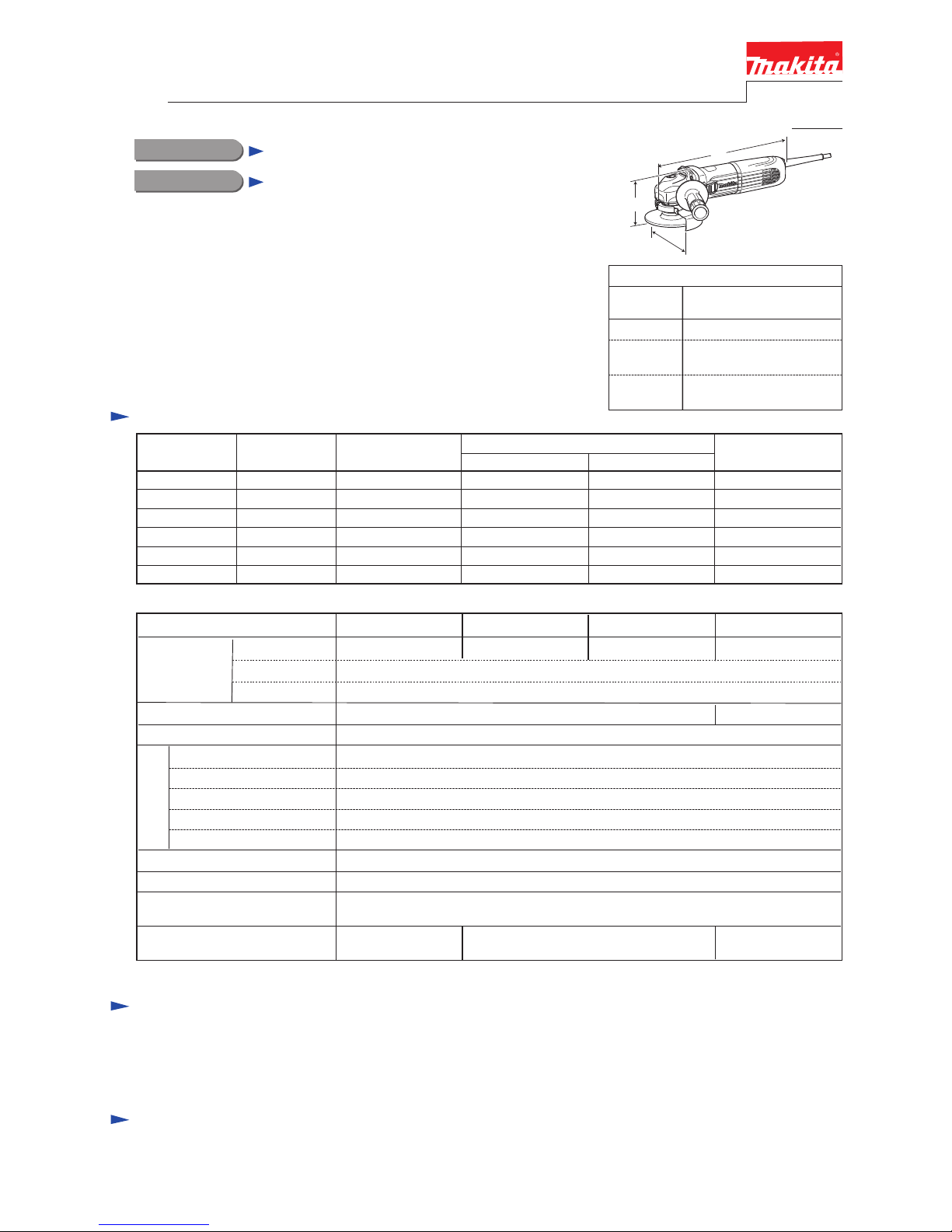
Dimensions: mm (")
Width (W)
Height (H)
Length (L)
Model No.
303 (11-7/8)
GA4040, GA4540,
GA5040, GA6040
117 (4-5/8), 130 (5-1/8),
140 (5-1/2), 171 (6-3/4)
111 (4-3/8), 116 (4-9/16),
116 (4-9/16), 116 (4-9/16)
Specification
Continuous Rating (W)
Voltage (V) Cycle (Hz)
Input Output
700
Max. Output (W)
110
120
220
230
240
11
10
5.3
5
4.8
50/60
50/60
50/60
50/60
50/60
1,100
1,100
1,100
1,100
1,100
1,300
1,300
1,300
1,300
1,300
Current (A)
700
127 9.1 50/60 ---
1,300
700
700
700
700
*1 with Side grip, Wheel cover, Inner flange, Lock nut
Model No.
No load speed: min.
ˉ¹=rpm
Diameter
Hole diameter
Wheel size:
mm (")
Protection against electric shock
Power supply cord: m (ft)
Weight according to
EPTA-Procedure 01/2003*1: kg (")
GA4040 GA6040
100 (4) 115 (4-1/2)
European countries except UK: 4.0 (13.2), Brazil, Australia: 2.0 (6.6)
Other countries: 2.5 (8.2)
11,000
150 (6)
Double insulation
22.23 (7/8)16 (5/8)
Max. thickness 6 (1/4)
Shock absorbing System
Mechanical brake
Super Joint System II
No
No
No
No
Constant speed control
Variable speed control by dial
Soft start
Electronic current limiter
Anti-restart function
Electronic
control
No
No
GA4540
125 (5)
2.3 (5.0) 2.4 (5.3) 2.5 (5.5)
GA5040
9,000
L
H
W
Depressed center wheels
Rubber pads
Dust collecting wheel guards
Abrasive discs
Wire brushes
Wheel covers for wire brushes
Diamond wheels
Abrasive cut off wheels
Wheel covers
Sanding lock nut
etc.
T
ECHNICAL INFORMATION
P 1/ 12
P 2/ 12
Repair
Apply Makita grease to the following portions designated with the black triangle and gray triangle to protect parts and
product from unusual abrasion.
[1] NECESSARY REPAIRING TOOLS
CAUTION: Repair the machine in accordance with “Instruction manual” or “Safety instructions”.
Code No. Description Use for
1R045 Gear extractor (Large) separate Armature from Gear housing cover
1R049 Drill chuck remover 15
fixing large Spiral bevel gear when removing Spindle
1R050 Drill chuck remover 22
1R232 Pipe 30 removing Cup ring and Ball bearing 6903ZZ from large Spiral bevel gear
1R258 V block supporting Bearing box
1R268 Spring pin extractor M3 disassembling Shaft lock mechanism
1R269 Bearing extractor removing Ball bearings 627DDW/ 696ZZ from Armature
1R281 Round bar for Arbor 7-50 removing Switch knob from Switch lever
1R286 Round bar for Arbor 12-50 removing large Spiral bevel gear section from Bearing box
1R291 Retaining ring S & R pliers removing Retaining ring S-9
1R340 Bearing retainer wrench removing Bearing retainer 20-33 from Bearing box
1R350 Ring 60 supporting Gear housing when disassembling Shaft lock mechanism
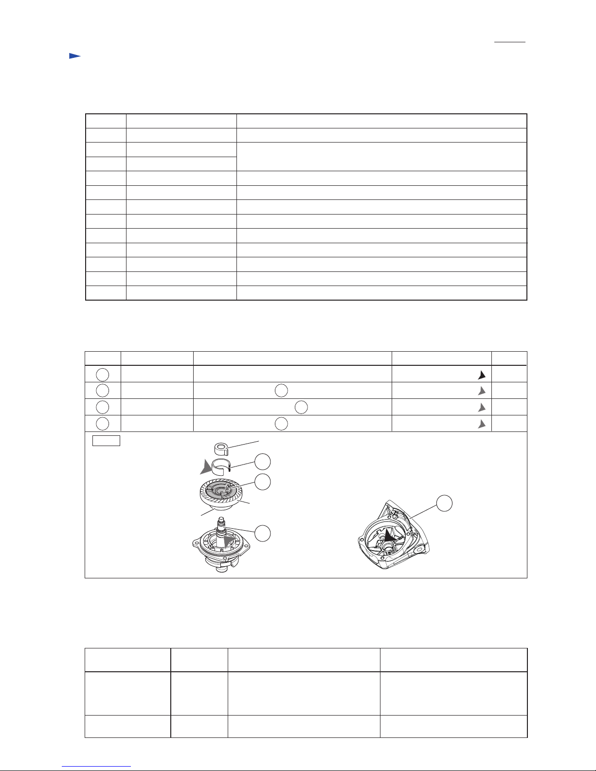
[2] LUBRICATION
Fig. 1
Item No. Description
Gear housing
C-type plate
Lubricant AmountPortion to lubricate
Coupling
Spindle
Model No.
GA4040 GA4540C
GA4540 GA5040C
GA5040 GA4542C
GA4040C GA5042C
GA6040 GA6042C
GA6040C
Smaller spiral bevel gear
(on armature shaft)
Larger spiral bevel gear
(on spindle)
10 teeth 38 teeth
9 teeth 41 teeth
Gear room 15 g
a little
a little
a little
70
56
1
Joint sleeve
Note: As listed below, the grinders use different spiral bevel gears, and they are not interchangeable.
Referring to this list, therefore, be sure to use correct gears for replacement.
Spiral bevel gear (large)
Ball bearing 6903ZZ
56
58
58
Outer surface where 58 Coupling contacts
Drum portion where 58 Coupling contacts
Cylindrical portion where 56 C-type plate contacts
Makita Grease FA No. 2:
Makita Grease FA No. 2:
Makita Grease FA No. 2:
Makita Grease SG No. 0:
1
70
[3] DISASSEMBLY/ASSEMBLY
[3] -1. Note in Disassemble (general)
No load
speed: min.ˉ¹
11,000
9,000
P 3/ 12
Repair
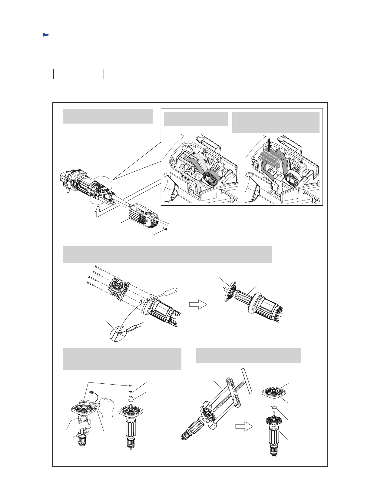
[3] DISASSEMBLY/ASSEMBLY
[3] -2. Armature, Spiral bevel gear [small one]
DISASSEMBLING
1. Remove Rear cover by unscrewing
one 4x18 Tapping screw.
(1) Remove Spiral bevel gear (small) from the drive end of Armature as drawn in Fig. 2.
4x18 Tapping screw
4. Unscrew four Tapping screws. Then separate Gear housing cover from Motor housing
while applying a slotted screwdriver to the groove on Gear housing cover.
Rear cover
2. Shift Spiral spring from
Carbon brush top.
3. Disconnect Carbon brush from
commutator by pulling up.
Note: No need to remove in this step.
Fig. 2
Groove on
Gear housing cover
Gear housing cover
Armature
Wrench 10
Flat washer 12
Gear housing
cover
Ball bearing
6001LLB
5. Remove M6 Hex nut to turn it with Wrench 10
counterclockwise. Then, remove Flat washer 6
and small Spiral bevel gear from Armature.
6. Remove Gear housing cover with 1R045.
Then, remove Flat washer 12.
Flat washer 6
Spiral bevel
gear (small)
M6 Hex nut
Armature
1R045
P 4/ 12
Repair
DISASSEMBLING
ASSEMBLING
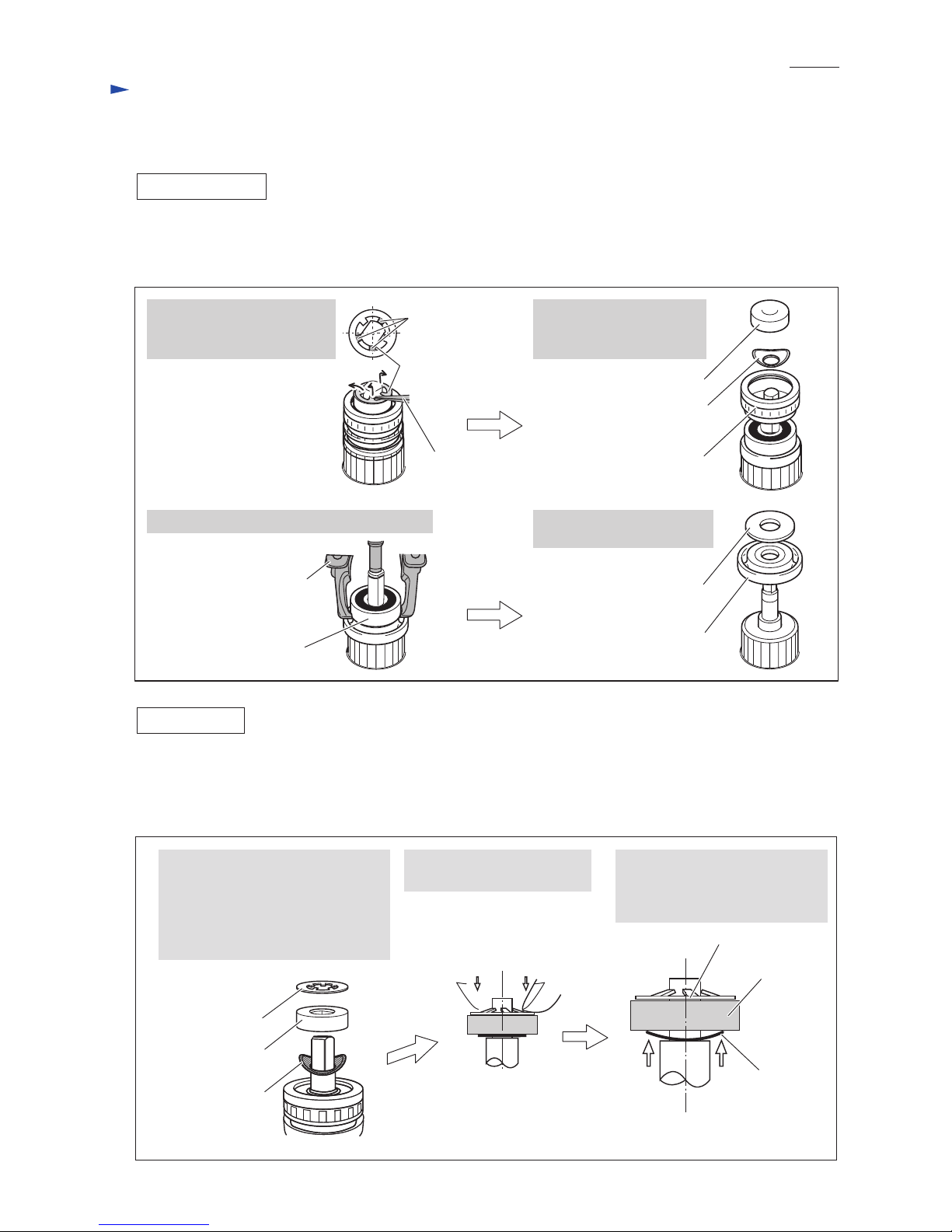
(2) Disassemble the commutator end of Armature as drawn in Fig. 3.
Note: This step is required for the models with electronic control system of GA4040C, GA4540C, GA5040C,
GA6040C, GA4542C, GA5042C, GA6042C.
Fig. 3
1. Pick up three tabs of
Self lock 6 with tweezers
to remove it from Armature.
2. Remove Magnet sleeve,
Wave washer 6 and
Labyrinth rubber ring 22.
3. Remove Ball bearing 627DDW with 1R269. 4. Remove Flat washer 7 and
Insulation washer.
Self lock 6
Tabs
Tweezers
Wave washer 6
Magnet sleeve
Labyrinth rubber ring 22
Ball bearing 627DDW
1R269
Flat washer 7
Insulation washer
(1) Assemble small Spiral bevel gear to Armature end by reversing the disassembly procedure. (Refer to Fig. 2)
(2) Assemble the commutator end of Armature as drawn in Fig. 4.
Note: This step is required for the models with electronic control system of GA4040C, GA4540C, GA5040C,
GA6040C, GA4542C, GA5042C, GA6042C.
Fig. 4
2. Press down Self lock 6 until
Wave washer 6 gets flat.
3. Magnet sleeve is stabilized
between Self lock 6 and
Wave washer 6 by the reaction
force of Wave washer 6.
1. Return tabs of Self lock 6 to their
normal shape before assembling.
Then, mount Wave washer 6 to
the commutator end of Armature.
Note: Be careful to their directions.
Refer to the drawings in Fig. 4.
Wave washer 6
Magnet sleeve
Self lock 6
Wave washer 6
Magnet sleeve
Self lock 6
[3] DISASSEMBLY/ASSEMBLY
[3] -2. Armature, Spiral bevel gear [small one] (cont.)
 Loading...