

Page 1
Original Instruction Manual
Instructions d’emploi d’origine
Originalbetriebsanleitung
Manuale di istruzioni originale
Originele gebruiksaanwijzing
Instrucciones de manejo originales
Instruções de serviço original
Original brugsanvisning
Πρωτότυπο εγχειρίδιο οδηγιών
Orijinal Kullanım Kılavuzu
Warning:
Read this instruction manual carefully before putting the Multi Function Power Head into operation and strictly observe the safety regulations!
Save instruction manual for future reference.
Avertissement :
Veuillez lire attentivement ce mode d’emploi avant d’utiliser l’outil multi-fonctions et respectez strictement les consignes de sécurité !
Conservez ce mode d’emploi pour vous y reporter ultérieurement.
Warnung:
Lesen Sie vor Verwendung des Multifunktions-Antriebes diese Bedienungsanleitung aufmerksam durch und halten Sie die
Sicherheitsregeln strikt ein!
Bewahren Sie die Anweisungen zum späteren Nachschlagen auf.
Avvertenza:
Leggere attentamente il presente manuale di istruzioni prima di mettere in funzione l’utensile multifunzione a benzina e rispettare
scrupolosamente le norme per la sicurezza.
Conservare il manuale di istruzioni per farvi riferimento in futuro.
Waarschuwing:
Lees deze gebruiksaanwijzing aandachtig door voordat u het multifunctionele aandrijfsysteem in gebruik neemt en houdt u te allen tijde
aan de veiligheidsinstructies!
Bewaar de gebruiksaanwijzing om deze in de toekomst te kunnen raadplegen.
Advertencia:
Lea atentamente este manual de instrucciones antes de utilizar el multifuncional y cumpla estrictamente la normativa de seguridad.
Guarde el manual de instrucciones para futuras consultas.
Aviso:
Leia cuidadosamente este manual de instruções antes de utilizar a Multifuncional a Gasolina e cumpra todas as normas de segurança!
Guarde o manual de instruções para referência futura.
Advarsel:
Læs denne brugsanvisning omhyggeligt igennem inden du anvender det multifunktionelle værktøjshoved og overhold
sikkerhedsbestemmelserne til mindste detalje!
Gem brugsanvisningen, så du har den til fremtidig brug.
Προειδοποιηση:
Πριν θέσετε σε λειτουργία τη Βενζινοκίνητη Κεφαλή Πολλαπλών Χρήσεων διαβάσετε προσεχτικά το εγχειρίδιο οδηγιών και εφαρμόσετε
αυστηρά τους κανονισμούς ασφαλείας!
Φυλάξτε το εγχειρίδιο οδηγιών για μελλοντική αναφορά.
Uyari:
Çok Fonksiyonlu Güç Başlığını kullanmaya başlamadan önce bu kullanım kılavuzunu dikkatli bir şekilde okuyun ve güvenlik talimatlarını
sıkı bir şekilde takip edin!
Kullanım kılavuzunu daha sonra başvurmak üzere saklayın.
EX2650LH
Page 2
English
(Original instructions)
Thank you very much for purchasing the MAKITA Multi Function Power Head.
We are pleased to recommend to you the MAKITA Multi Function Power Head
which is the result of a long development programme and many years of
knowledge and experience.
Please read this booklet which refers in detail to the various points that will
demonstrate its outstanding performance. This will assist you to obtain the best
possible result from your MAKITA Multi Function Power Head.
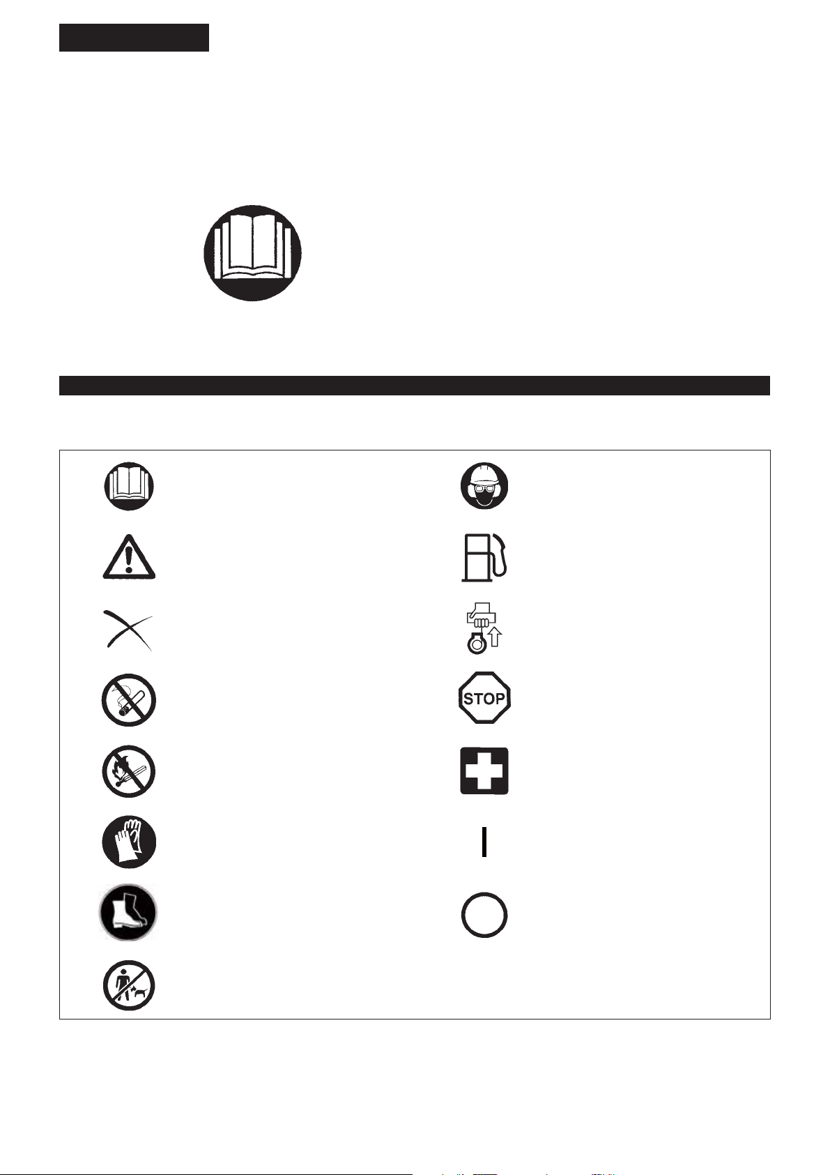
SYMBOLS
You will note the following symbols when reading the instructions manual.
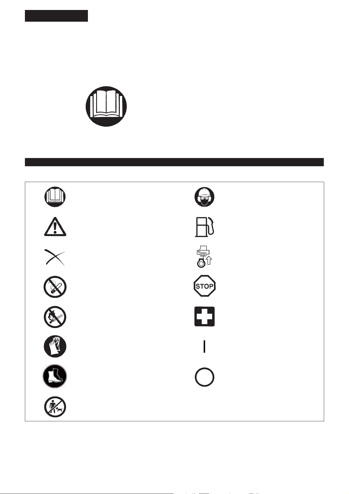
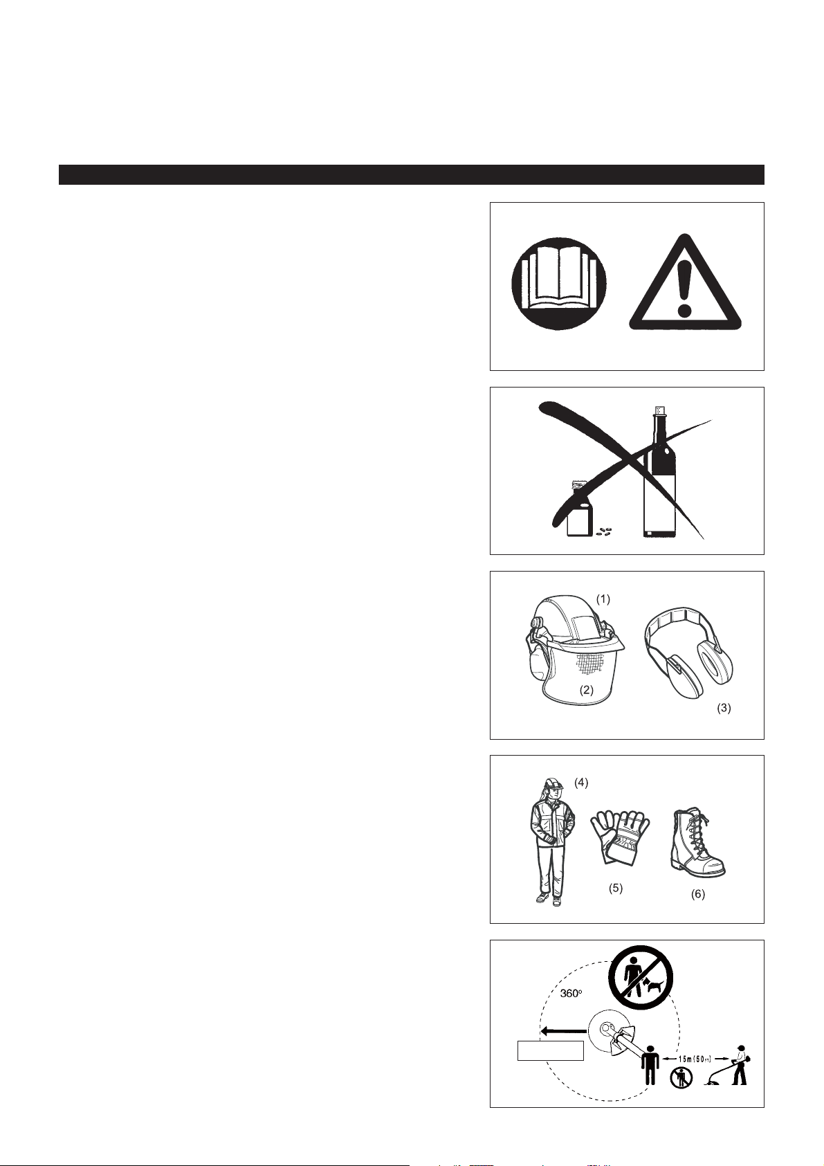
Read instruction manual and follow the
warnings and safety precautions!
Table of Contents Page
Symbols .........................................................................2
Safety instructions .........................................................3
Technical data................................................................7
Approved attachments...................................................8
Designation of parts.......................................................9
Mounting of handle ......................................................10
Mounting attachment ...................................................10
Disassembling ............................................................. 11
Before start of operation ..............................................12
Correct handling of machine........................................14
Points in operation and how to stop ............................14
Servicing instructions...................................................17
Storage ........................................................................20
Wear protective helmet, eye and ear
protection!
Take particular care and attention! Fuel (Gasoline)
Forbidden! Engine-manual start
No smoking! Emergency stop
No open flame! First aid
Protective gloves must be worn! ON/START
Wear sturdy boots with nonslip soles.
Steeltoed safety boots are recommended!
OFF/STOP
Keep the area of operation clear of all
persons and pets!
2
Page 3

Intended use of the machine
This multi function power head is intended for driving an approved attachment
listed in this instruction manual. Never use the machine for the other purpose.
SAFETY INSTRUCTIONS
General instructions
To ensure correct operation, user has to read this instruction manual to make himself familiar with the handling of the Multi Function Power Head. Users
insufficiently informed will risk danger to themselves as well as others due to
improper handling.
It is recommended only to lend the Multi Function Power Head to people who have proven to be experienced with Multi Function Power Heads.
Always hand over the instruction manual.
First users should ask the dealer for basic instructions to familiarize oneself with the handling of an engine powered cutter.
Children and young persons aged under 18 years must not be allowed to operate the Multi Function Power Head. Persons over the age of 16 years
may however use the device for the purpose of being trained only whilst
under supervision of a qualified trainer.
Use Multi Function Power Heads with the utmost care and attention. Operate the Multi Function Power Head only if you are in good physical -
condition. Perform all work calmly and carefully. The user has to accept
liability for others.
Never use the Multi Function Power Head after consumption of alcohol or drugs, or if feeling tired or ill.
National regulation can restrict the use of the machine. -
Personal protective equipment
The clothing worn should be functional and appropriate, i.e. it should be tight- fitting but not cause hindrance. Do not wear either jewelry or clothing which
could become entangled with bushes or shrubs.
In order to avoid either head-, eye-, hand-or foot injuries as well as to protect your hearing the following protective equipment and protective clothing must
be used during operation of the Multi Function Power Head.
Always wear a helmet where there is a risk of falling objects. The protective helmet (1) is to be checked at regular intervals for damage and is to be
replaced at the latest after 5 years. Use only approved protective helmets.
The visor (2) of the helmet (or alternatively goggles) protects the face from flying debris and stones. During operation of the Multi Function Power Head
always wear goggles, or a visor to prevent eye injuries.
Wear adequate noise protection equipment to avoid hearing impairment (ear muffs (3), ear plugs etc.).
The work overalls (4) protect against flying stones and debris. We strongly recommend that the user wears work overalls.
Special gloves (5) made of thick leather are part of the prescribed equipment and must always be worn during operation of the Multi Function Power Head.
When using the Multi Function Power Head, always wear sturdy shoes (6) with a non-slip sole. This protects against injuries and ensures a good footing.
Starting up the Multi Function Power Head
Please make sure that there are no children or other people, also pay attention to any animals in the working vicinity.
Make sure that the attachment is attached in place, the control lever for easy action and check for proper functioning of the lock-off lever.
Motion of the attachment during idling speed is not allowed. Check with your dealer for adjustment if in doubt. Check for clean and dry handles and test
the function of the start/stop switch.
Diagrammatic figure
15 Meters
3
Page 4
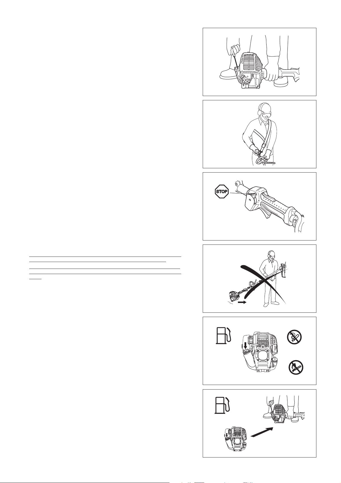
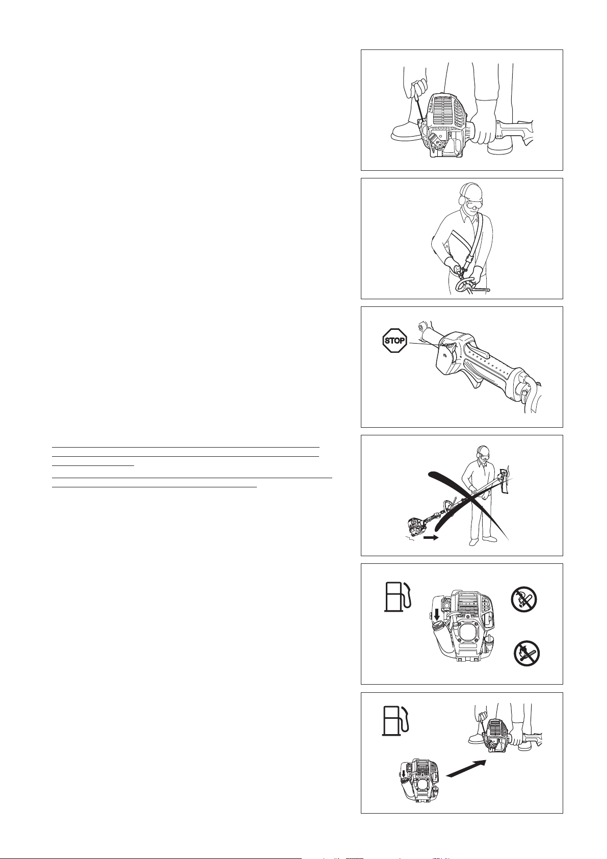
Start the Multi Function Power Head only in accordance with the instructions.
Do not use any other methods for starting the engine! Use the Multi Function Power Head and the tools only for such applications -
as specified.
Only start the Multi Function Power Head engine, after the entire assembly -
is done. Operation of the device is only permitted after all the appropriate
accessories are attached!
Before starting make sure that the attachment has no contact with hard objects such as branches, stones etc. as the attachment will revolve when
starting.
The engine is to be switched off immediately in case of any engine problems. Should the attachment hit stones or other hard objects, immediately switch off -
the engine and inspect the attachment.
Operate the Multi Function Power Head only with the shoulder strap attached -
which is to be suitably adjusted before putting the Multi Function Power Head
into operation. It is essential to adjust the shoulder strap according to the user
size to prevent fatigue occurring during use. Never hold the cutter with one
hand during use.
During operation always hold the Multi Function Power Head with both hands. Always ensure a safe footing.
Operate the Multi Function Power Head in such a manner as to avoid inhalation of the exhaust gases. Never run the engine in enclosed rooms (risk
of gas poisoning). Carbon monoxide is an odorless gas.
Switch off the engine when resting and when leaving the Multi Function Power Head unattended, and place it in a safe location to prevent danger to
others or damage to the machine.
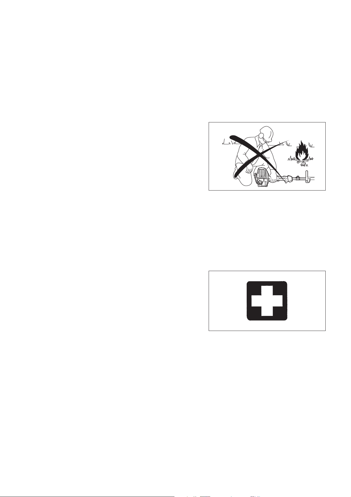
Never put the hot Multi Function Power Head onto dry grass or onto any combustible materials.
All protective installations and guards supplied with the machine must be used during operation.
Never operate the engine with faulty exhaust muffler. Shut off the engine during transport. During transport over long distances the tool protection included with the -
equipment must always be used.
Ensure safe position of the Multi Function Power Head during car -
transportation to avoid fuel leakage.
When transporting the Multi Function Power Head, ensure that the fuel tank -
is completely empty.
When unloading the Mul - ti Function Power Head from the truck, never drop
the engine to the ground or this may severely damage the fuel tank.
Except in case of emergency, never drop or cast the Multi Function Power -
Head to the ground or this may severely damage the Multi Function Power
Head.
Remember to lift the entire equipment from the ground when moving the equipment. Dragging the fuel tank is highly dangerous and will cause damage
and leakage of fuel, possibly causing fire.
If the equipment gets heavy impact or fall, check the condition before continuing work. Check the fuel system for fuel leakage and the controls
and safety devices for malfunction. If there is any damage or doubt, ask our
authorized service center for the inspection and repair.
• Resting
• Transport
• Refuelling
• Maintenance
• Tool replacement
Refuelling
Shut off the engine during refuelling, keep away from open flames and do not smoke.
Avoid skin contact with mineral oil products. Do not inhale fuel vapor. Always wear protective gloves during refuelling. Change and clean protective clothing
at regular intervals.
Take care not to spill either fuel or oil in order to prevent soil contamination (environmental protection). Clean the Multi Function Power Head immediately
after fuel has been spilt.
Avoid any fuel contact with your clothing. Change your clothing instantly if fuel has been spilt on it (to prevent clothing catching fire).
Inspect the fuel cap at regular intervals making sure that it can be securely fastened and does not leak.
Carefully tighten the fuel tank cap. Change location to start the engine (at least 3 meters away from the place of refuelling).
Never refuel in closed rooms. Fuel vapors accumulate at ground lever (risk of explosions).
Only transport and store fuel in approved containers. Make sure the fuel stored is not accessible to children.
4
3 meters
Page 5

Method of operation
Only use the Multi Function Power Head in good light and visibility. During the winter season beware of slippery or wet areas, ice and snow (risk of slipping).
Always ensure a safe footing.
Never stand on a ladder and run the Multi Function Power Head. Never climb up into trees to perform cutting operation with the Multi Function -
Power Head.
Never work on unstable surfaces. Before using attachment, the attachment must have reached full working -
speed.
Take a rest to prevent loss of control caused by fatigue. We recommend to -
take a 10 to 20-minute rest every hour.
Maintenance instructions
Have your equipment serviced by our authorized service center, always using only genuine replacement parts. Incorrect repair and poor maintenance can
shorten the life of the equipment and increase the risk of accidents.
Operate the Multi Function Power Head with as little noise and contamination as possible. In particular check the correct setting of the carburetor.
Clean the Multi Function Power Head at regular intervals and check that all screws and nuts are well tightened.
Never service or store the Multi Function Power Head in the vicinity of naked flames.
Always store the Multi Function Power Head in locked rooms and with an emptied fuel tank.
Observe the relevant accident prevention instructions issued by the relevant trade associations and by the insurance companies.
Do not perform any modifications on the Multi Function Power Head as this will endanger your safety.
The performance of maintenance or repair work by the user is limited to those activities as described in the instruction manual. All other work is
to be done by an Authorized Service Agent. Use only genuine spare parts and accessories released and supplied by MAKITA.
Use of non-approved accessories and tools means increased risk of accidents.
MAKITA will not accept any liability for accidents or damage caused by the use of non-approved attachments and fixing devices of attachments,
or accessories.
First aid
In case of accident make sure that a first-aid box is available in the vicinity of
the cutting operations. Immediately replace any item taken from the first aid box.
When asking for help, please give the following
information:
Place of accident What happened Number of injured persons Kind of injuries Your name -
Vibration
People with poor circulation who are exposed to excessive vibration may experience injury to blood vessels or the nervous system. Vibration may cause the following symptoms to occur in the fingers, hands or wrists: “Falling asleep” (numbness), tingling, pain, stabbing sensation,
alteration of skin color or of the skin. If any of these symptoms occur, see a physician!
To reduce the risk of “white finger disease”, keep your hands warm during operation and well maintain the equipment and accessories. -
5
Page 6

EC DECLARATION OF CONFORMITY
We Makita Corporation as the responsible manufacturer declare that the following Makita Machines:
Designation of Machine: Multi Function Power Head
Model No./ Type: EX2650LH
Specifications: see “TECHNICAL DATA EX2650LH” table
are of series production and
Conforms to the following European Directives:
2000/14/EC, 2006/42/EC
And are manufactured in accordance with the following standards or standardised documents:
EN/ISO11806, EN709, EN/ISO10517, EN/ISO11680, EN/ISO12100
The technical documentation is kept by:
Makita International Europe Ltd., Technical Department,
Michigan Drive, Tongwell,
Milton Keynes, Bucks MK15 8JD, England
The conformity assessment procedure required by Directive 2000/14/EC was in accordance with annex V.
EX2650LH with EM400MP (Brushcutter Attachment)
EX2650LH with EM401MP (Brushcutter Attachment)
EX2650LH with ER400MP (String Trimmer Attachment)
EX2650LH with EN400MP (Hedge Trimmer Attachment)
EX2650LH with EN400MP (Hedge Trimmer Attachment) and LE400MP (Shaft Extension Attachment)
Measured Sound Power Level: 108.5 dB (A)
Guaranteed Sound Power Level: 113 dB (A)
Measured Sound Power Level: 102.7 dB (A)
Guaranteed Sound Power Level: 105 dB (A)
Measured Sound Power Level: 109.2 dB (A)
Guaranteed Sound Power Level: 116 dB (A)
Measured Sound Power Level: 103.8 dB (A)
Guaranteed Sound Power Level: 109 dB (A)
Measured Sound Power Level: 104.0 dB (A)
Guaranteed Sound Power Level: 106 dB (A)
The EC-Type Examination Certificate No. as a pole saw with EY400MP, EY401MP, LE400MP is:
4811004.11016
The EC-Type Examination per 2006/42/EC was performed by:
DEKRA Testing and Certification GmbH
Enderstraße 92b
01277 Dresden, Germany
Identification No. 2140
30. 1. 2012
Tomoyasu Kato
Director
Makita Corporation
3-11-8, Sumiyoshi-cho,
Anjo, Aichi, 446-8502, JAPAN
6
Page 7

TECHNICAL DATA EX2650LH
Model
EX2650LH
Loop handle
Dimensions: length x width x height (without cutting blade)
with barrier
Dimensions: length x width x height (without cutting blade)
without barrier
mm 975 x 323 x 241
mm 975 x 242 x 241
Mass (without plastic guard and cutting blade) kg 4.6
Volume (fuel tank) L 0.6
Volume (oil reservoir) L 0.08
Engine displacement cm
3
25.4
Maximum engine performance kw 0.77 at 7,000 min
Engine speed at recommended max. spindle speed min
Maximum spindle speed (corresponding) min
-1
-1
8,500
6,500
Maximum fuel consumption kg/h 0.33
Maximum specific fuel consumption g/kwh 408
Idling speed min
Clutch engagement speed min
-1
-1
3,000
3,900
Carburetor type WALBRO WYL
Ignition system type Solid state ignition
Spark plug type NGK CMR4A
Electrode gap mm 0.7 - 0.8
Fuel Automobile gasoline
Engine oil
SAE 10W-30 oil of API Ciassification,
Class SF or higher (4-stroke engine for automobile)
-1
Vibration
Attachment a
Right handle
(Rear grip)
(m/s2) Uncertainty K (m/s2)a
hv eq
hv eq
Left handle
(Front grip)
(m/s2) Uncertainty K (m/s2)
Applicable
standards
EM400MP 6.5 1.2 5.9 1.8 ISO 22867
EM401MP 5.6 2.1 4.8 1.0 ISO 22867
ER400MP 7.1 2.8 5.5 2.7 ISO 22867
EY400MP 9.4 2.0 4.2 2.0 ISO 22867
EY400MP + LE400MP 4.8 2.0 3.4 2.0 ISO 22867
EY401MP 6.5 2.0 3.8 2.0 ISO 22867
EY401MP + LE400MP 5.6 2.0 3.4 2.0 ISO 22867
EN400MP 8.4 1.8 5.0 0.7 ISO 10517
EN400MP + LE400MP 8.0 1.7 4.3 0.7 ISO 10517
KR400MP 5 1.1 4.4 2.3 ISO 22867
EJ400MP 7.1 1.5 4.9 1.5 ISO 22867
EJ400MP + LE400MP 6.4 0.6 4.0 0.7 ISO 22867
7
Page 8

Noise
Attachment L
Sound pressure level average Sound power level average
PA eq
Uncertainty K L
WA eq
Uncertainty K
Applicable
standards
EM400MP 95.0 4.4 105.5 3.3 ISO 22868
EM401MP 89.9 3.6 99.7 2.7 ISO 22868
ER400MP 97.9 4.2 106.2 4.0 ISO 22868
EY400MP 93.0 2.5 104.5 2.5 ISO 22868
EY400MP + LE400MP 90.3 2.5 107.8 2.5 ISO 22868
EY401MP 92.6 2.5 104.7 2.5 ISO 22868
EY401MP + LE400MP 90.5 2.5 107.9 2.5 ISO 22868
EN400MP 93.1 4.4 102.9 4.8 ISO 10517
EN400MP + LE400MP 87.8 1.9 103.0 2.0 ISO 10517
KR400MP 93.7 2.6 99.7 1.2 ISO 22868
EJ400MP 89.0 2.3 99.8 1.1 ISO 22868
EJ400MP + LE400MP 88.1 2.2 100.8 2.3 ISO 22868
APPROVED ATTACHMENTS
ATTACHMENTS Models
Brushcutter Attachment EM400MP, EM401MP
String Trimmer Attachment ER400MP
Pole Saw Attachment EY400MP, EY401MP
Hedge Trimmer Attachment EN400MP
Cultivator Attachment KR400MP
Coffee Harvester Attachment EJ400MP
Shaft Extension Attachment LE400MP
8
Page 9
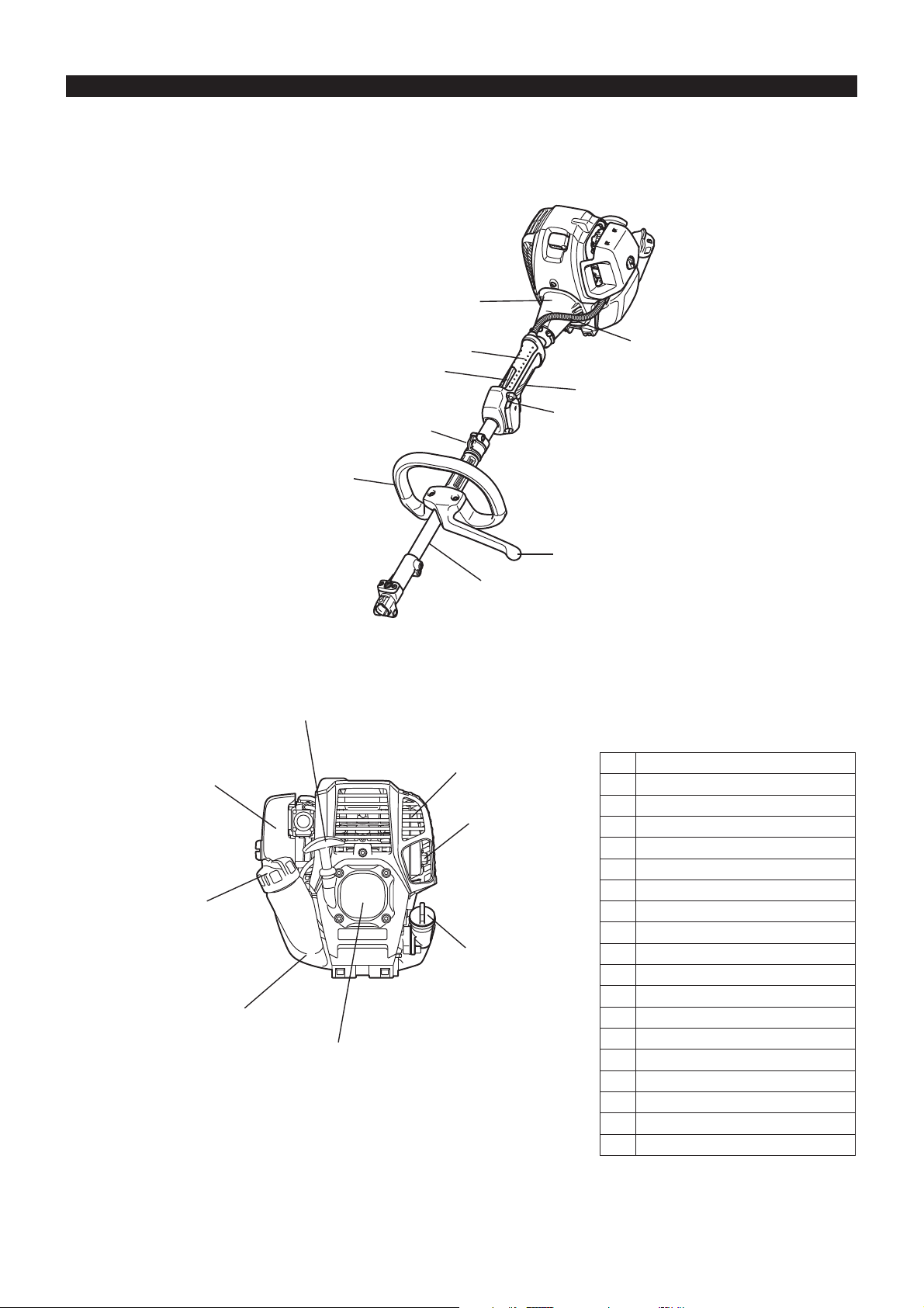
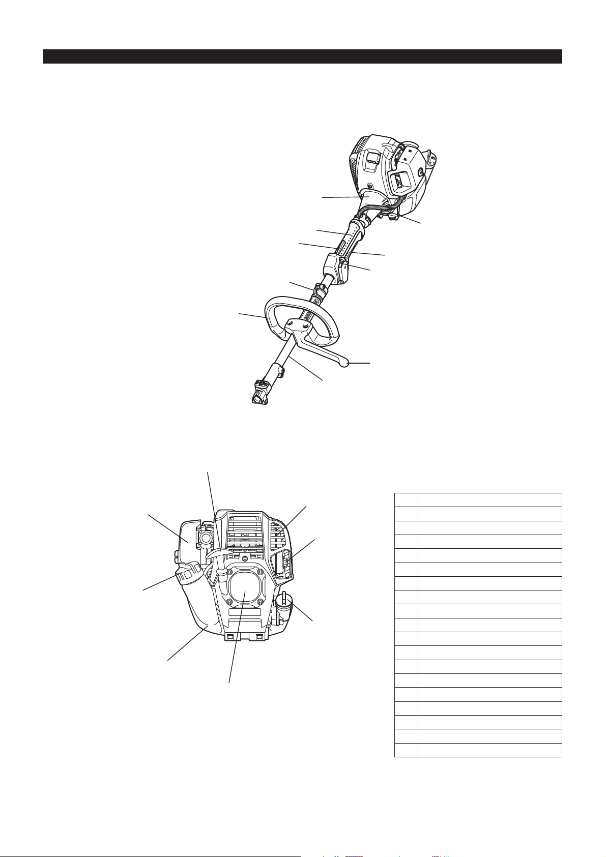
DESIGNATION OF PARTS
EX2650LH
6
14
7
12
11
10
4
8
9
18
13
15
3
5
16
17
1
2
GB DESIGNATION OF PARTS
1 Fuel tank
2 Rewind starter
3 Air cleaner
4 I-O switch (on/off)
5 Exhaust muffler
6 Clutch case
7 Rear grip
8 Hanger
9 Handle
10 Throttle lever
11 Lock-off lever
12 Control cable
13 Shaft
14 Fuel filler cap
15 Starter knob
16 Exhaust pipe
17 Oil cap
18 Barrier*
Note: In some countries, the barrier is not
provided with the tool.
9
Page 10
MOUNTING OF HANDLE
CAUTION: Before doing any work on the Multi Function Power Head, always
stop the engine and pull the spark plug connector off the spark plug.
Always wear protective gloves!
CAUTION: Start the Multi Function Power Head only after having assembled it
completely.
Assembling loop handle
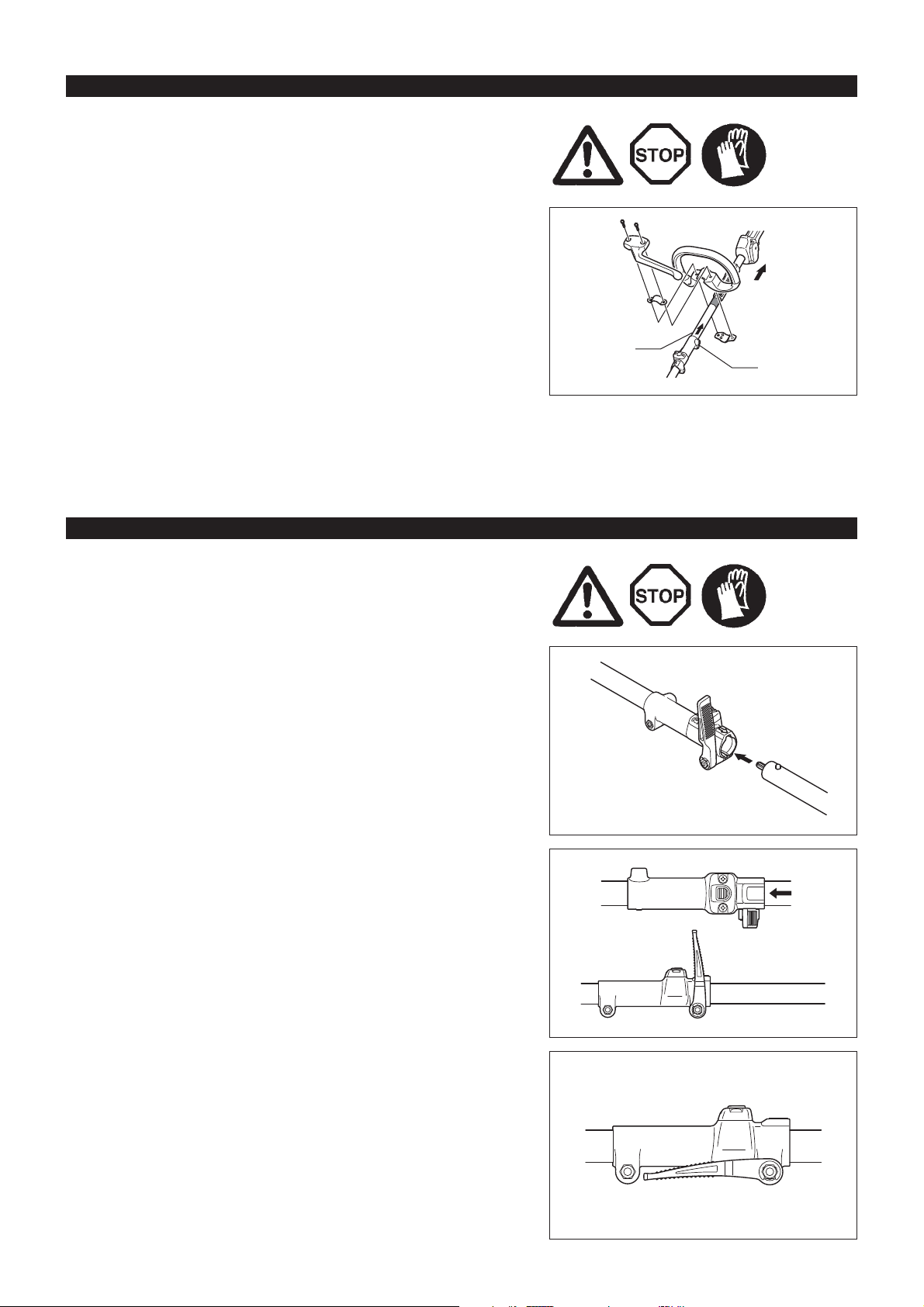
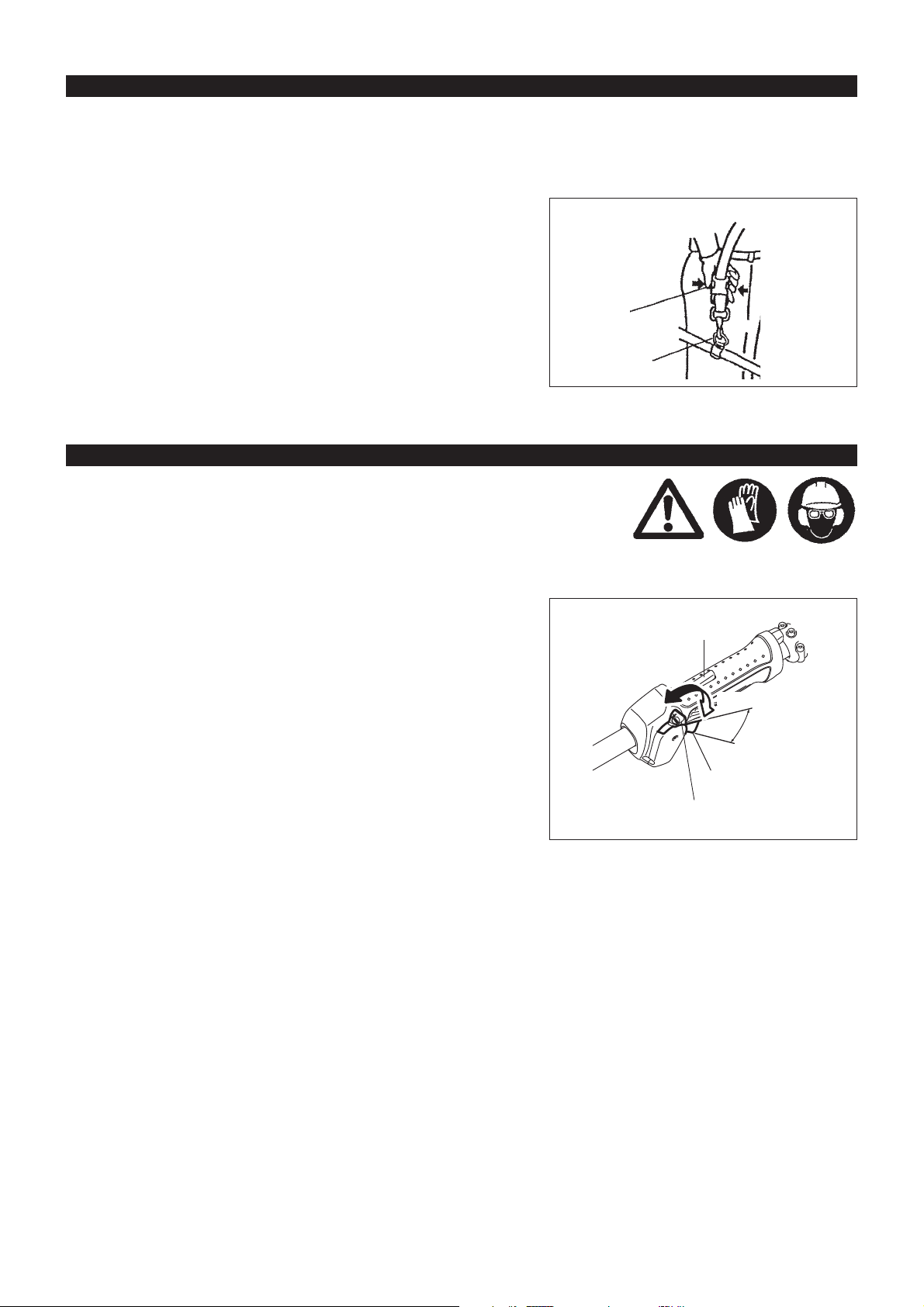
Securely fit the barrier and grip onto the shaft pipe with two screws and clamps. At this time, put the barrier on the left side of the machine as
illustrated.
Make sure that the grip/barrier assembly is located between the spacer and the arrow mark. Do not remove or shrink the spacer.
Once assembled, do not remove the barrier. -
CAUTION: Never install the grip on the label or joint.
Note: In some countries, the barrier and arrow mark are not provided with the
tool.
MOUNTING ATTACHMENT
CAUTION: Before doing any work on the Multi Function Power Head, always
stop the engine and pull the spark plug connector off the spark plug.
Always wear protective gloves!
CAUTION: Start the Multi Function Power Head only after having assembled it
completely.
Engine
Arrow mark
Joint
Assembly
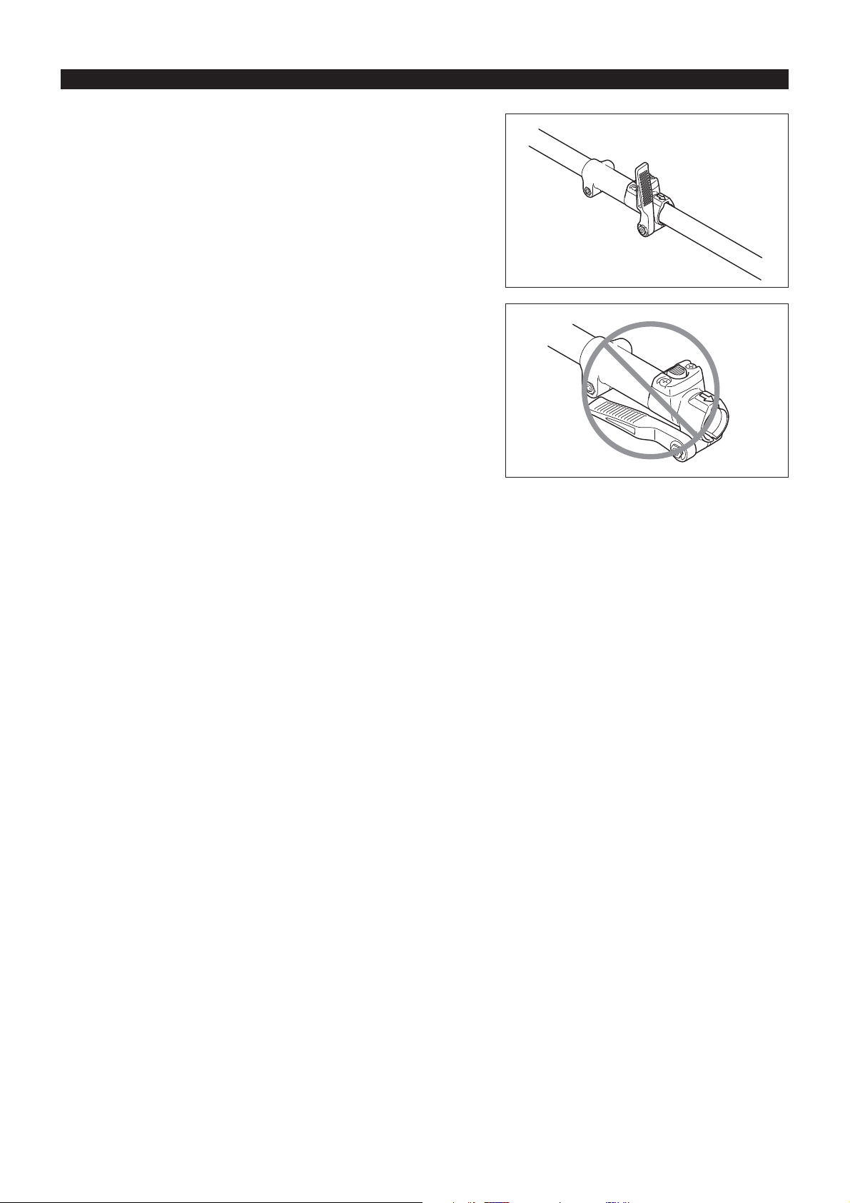
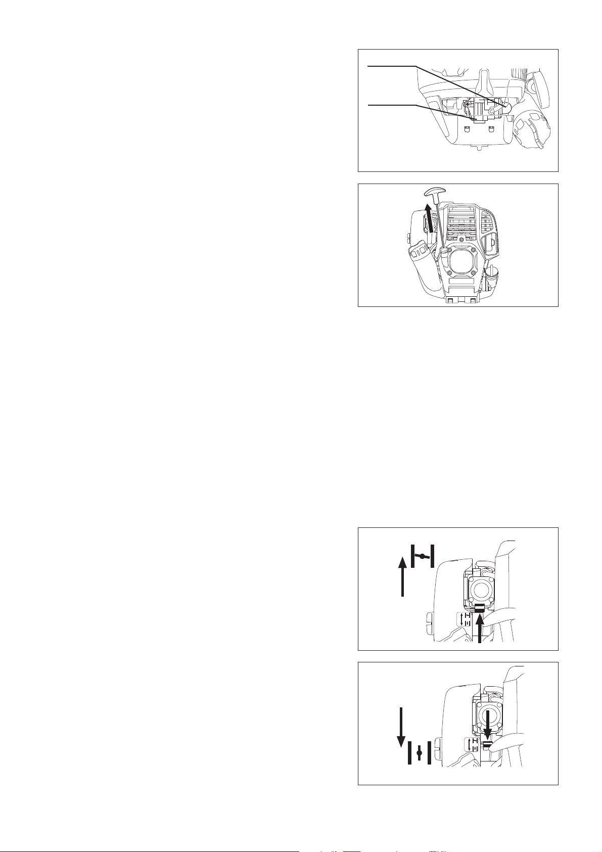
Loosen lever. Align the attachment’s pin with the joint’s groove and insert pin. Insert attachment up to the arrow position of attachment. -
And, check to see that button has risen.
Tighten lever. -
(See diagram on right for guideline.)
10
Page 11
DISASSEMBLING
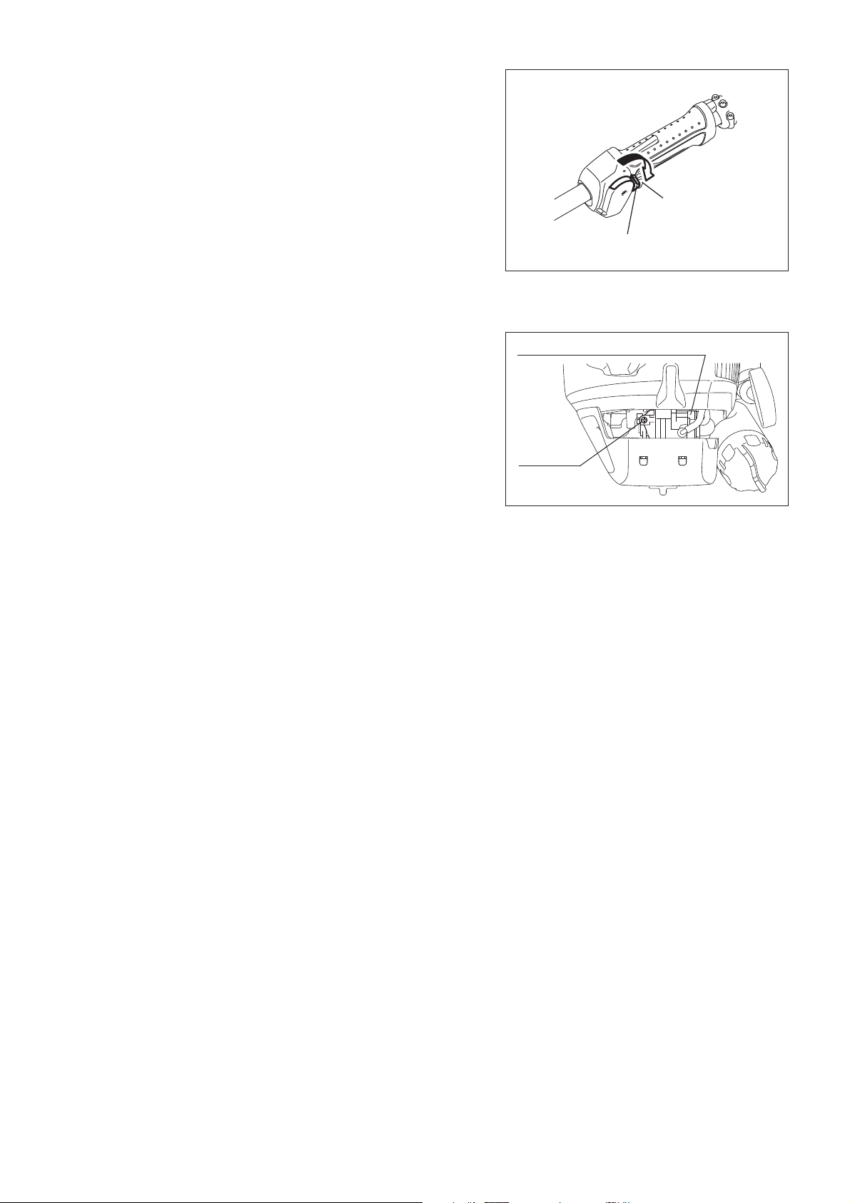
Loosen lever. Press button and extract attachment. -
(As much as possible, try to extract the attachment in a straight line.)
Note:
Do not leave the lever in a tightened state when attachment is not attached. -
11
Page 12
BEFORE START OF OPERATION
Inspection and refill of engine oil
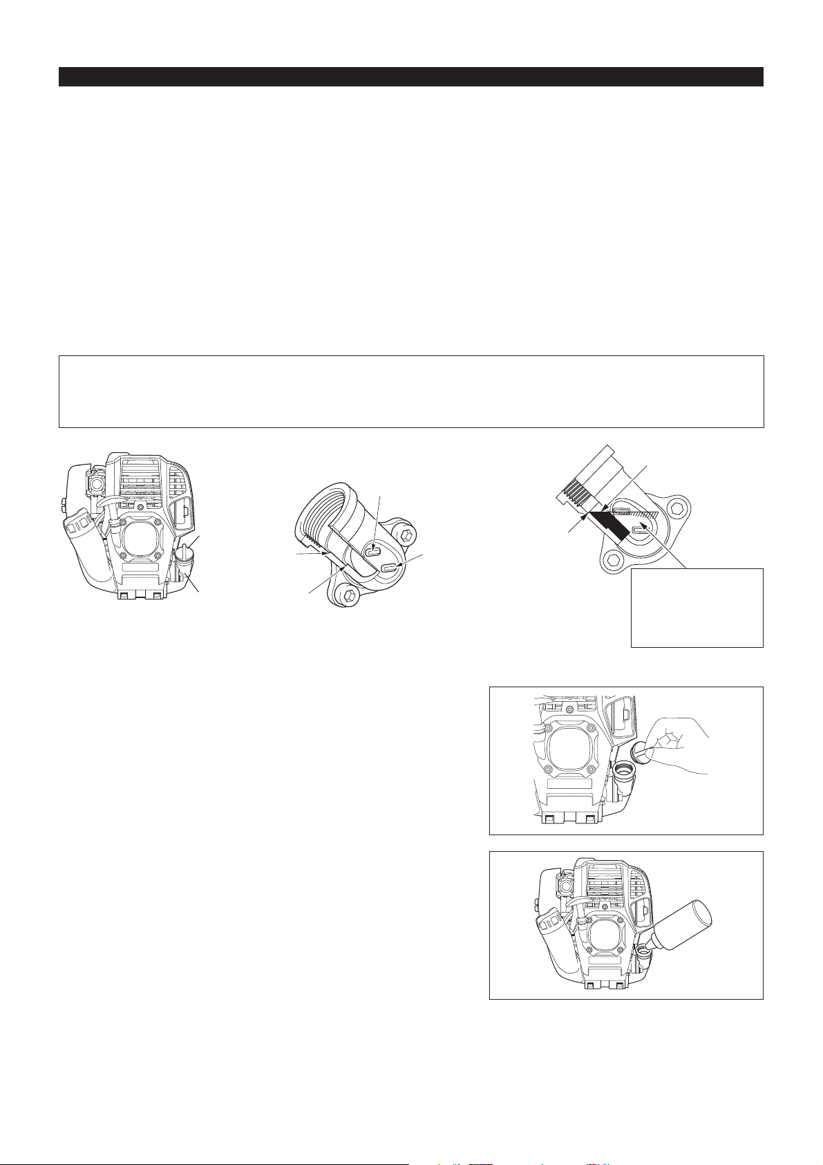
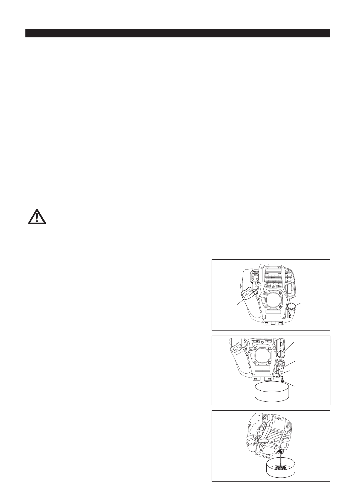
Perform the following procedure, with the engine cooled down. Set the engine level, remove oil cap (Fig. 1), and check to see whether or not there is oil in the range between the upper limit and lower limit -
marks of the oil pipe (Fig. 2).
Top up with oil to upper limit mark if oil is insufficient (oil level is close to lower limit mark) (Fig. 3). The area surrounding the external marks is transparent, so the amount of oil inside can be checked without having to remove the oil cap. -
However, if oil pipe becomes extremely dirty, visibility may be lost, and oil level will have to be checked against stepped section on inside of
oil pipe.
For reference, the oil refill time is about 10h (every 10 refuellings). If the oil changes in color or mixes with dirt, replace it with new one. (For the interval and method of replacement, refer to P 17)
Recommended oil: SAE 10W-30 oil of API Classification, Class SF or higher (4-stroke engine for automobile)
Oil volume: Approx. 0.08L
Note: If the engine is not kept upright, oil may go into around the engine, and may be refilled excessively.
If the oil is filled above the limit, the oil may be contaminated or may catch fire with white smoke.
Point 1 in Replacement of oil: “Oil cap”
Remove dust or dirt near the oil refill port, and detach the oil cap. Keep the detached oil cap free of sand or dust. Otherwise, any sand or dust adhering to the oil cap may cause irregular oil circulation or -
wear on the engine parts, which will result in troubles.
Oil cap
Internal stepped
section (upper
limit)
Oil pipe
Fig. 1
(1) Keep the engine level, and detach the oil cap.
(2) Fill with oil to upper limit mark. (see Fig. 3)
Use oil bottle when filling.
Internal stepped
section (lower
limit)
External mark
(upper limit)
External mark
(lower limit)
Fig. 2 Oil pipe Fig. 3
Top up with oil until
oil level reaches
internal stepped
section (upper
limit).
Oil
The area between the
external upper and lower
limits is transparent, so
oil level can be checked
externally against these
marks.
(3) Securely tighten the oil cap. Insufficient tightening may cause oil leakage.
12
Page 13
Note
Do not replace oil with the engine in a tilted position.•
Filling with oil while engine is tilted leads to overfilling which causes oil contamination and/or white smoke.•
Point 2 in Replacement of oil: “If oil spills out”
If oil spills out between the fuel tank and engine main unit, the oil is sucked into through the cooling air intake port, which will contaminate the engine. Be sure to wipe out spilt oil before start of operation.
REFUELING
Handling of fuel
It is necessary to handle fuel with utmost care. Fuel may contain substances similar to solvents. Refueling must be performed in a sufficiently
ventilated room or in the open air. Never inhale fuel vapor, and keep fuel away from you. If you touch fuel repeatedly or for a long time, the
skin becomes dry, which may cause skin disease or allergy. If fuel enters into the eye, clean the eye with fresh water. If your eye remains still
irritated, consult your doctor.
Storage period of fuel
Fuel should be used up within a period of 4 weeks, even if it is kept in a special container in a well-ventilated shade.
If a special container is not used or if the container is not covered, fuel may deteriorate in one day.
STORAGE OF MACHINE AND REFILL TANK
Keep the machine and tank at a cool place free from direct sunshine. Never keep the fuel in the cabin or trunk. -
Fuel
The engine is a four-stroke engine. Be sure to use an automobile gasoline (regular gasoline or premium gasoline).
Points for fuel
Never use a gasoline mixture which contains engine oil. Otherwise, it will cause excessive carbon accumulation or mechanical troubles. Use of deteriorated oil will cause irregular startup. -
Refueling
WARNING: INFLAMMABLES STRICTLY PROHIBITED
Gasoline used: Automobile gasoline (unleaded gasoline)
Loosen the tank cap a little so that there will be no difference in atmospheric pressure.
Detach the tank cap, and refuel, discharging air by tilting the fuel tank so that the refuel port will be oriented upward. (Never refill fuel full to the oil refill
port.)
Wipe well the periphery of the tank cap to prevent foreign matter from entering into the fuel tank.
After refueling, securely tighten the tank cap. -
If there is any flaw or damage on the tank cap, replace it.•
The tank cap is consumable, and therefore should be renewed every two to •
three years.
Fuel upper limit
Fuel tank
Fuel tank cap
13
Page 14
CORRECT HANDLING OF MACHINE
Attachment of shoulder strap
Adjust the strap to the suitable length for your operation. -
Detachment
In an emergency, push the notches (1) at both sides, and you can detach the machine from you.
Be extremely careful to maintain control of the machine at this time. Do not
allow the machine to be deflected toward you or anyone in the work vicinity.
WARNING: Failure to maintain complete control of the machine at all could
result in serious bodily injury or DEATH.
POINTS IN OPERATION AND HOW TO STOP
Observe the applicable accident prevention regulations!
(1)
Hanger
STARTING
Move at least 3 m away from the place of refuelling. Place the Multi Function Power Head on a clean piece of ground taking care that the
attachment does not come into contact with the ground or any other objects.
A: Cold start
1) Set this machine on a flat space.
2) Set the I-O switch (1) to OPERATION.
OPERATION
Lock-off lever
STOP
Throttle lever
(1)
High speed
Low speed
14
Page 15
3) Primer pump
Continue to push the primer pump until fuel enters into the primer pump.
(In general, fuel enters into the primer pump by 7 to 10 pushes.)
If the primer pump is pushed excessively, an excess of gasoline returns to
the fuel tank.
4) Recoil starter
Pull the start knob gently until it is hard to pull (compression point). Then,
return the start knob, and pull it strongly.
Never pull the rope to the full. Once the start knob is pulled, never release
your hand immediately. Hold the start knob until it returns to its original
point.
5) Warm-up operation
Continue warm-up operation for 2 to 3 minutes.
Note: In case of excessive fuel intake, remove the spark plug and pull the starter handle slowly to remove excess fuel. Also, dry the electrode
section of the spark plug.
Primer pump
Carburetor
Caution during operation:
If the throttle lever is opened fully in a no-load operation, the engine rotation is increased to 10,000 min-1 or more. Never operate the engine at a
higher speed than required and at an approximate speed of 6,000 - 8,500 min
-1
.
B: Startup after warm-up operation
1) Push the primer pump repeatedly.
2) Keep the throttle lever at the idling position.
3) Pull the recoil starter strongly.
4) If it is difficult to start the engine, open the throttle by about 1/3.
Pay attention to the attachment which may rotate.
At times, such as winter, when starting the engine
CLOSE
is difficult
Operate choke lever with the following procedure when starting engine.
After implementing startup steps 1) to 3), set choke lever to the CLOSE •
position.
Implement startup step 4) and start engine.•
Once engine starts, set choke lever to the OPEN position.•
Implement startup step 5) and complete warm up.•
CAUTION: If a bang (explosive sound) is heard and the engine stops, or the
CAUTION: If the choke lever is left in the CLOSE position, and the starter knob
just-started engine stalls before the choke lever is operated, return
the choke lever to the OPEN position, and pull the starter knob a
few times again to start the engine.
merely pulled repeatedly, too much fuel will be sucked in, and the
engine will become difficult to start.
15
OPEN
Page 16
STOPPING
1) Release the throttle lever (2) fully, and when the engine rpm has lowered,
set the I-O switch to STOP the engine will now stop.
2) Be aware that the attachment may not stop immediately and allow it to slow
down fully.
ADJUSTMENT OF LOW-SPEED ROTATION (IDLING)
When it is necessary to adjust the low-speed rotation (idling), perform it by the carburetor adjusting screw.
STOP
(2)
(1)
CHECKUP OF LOW-SPEED ROTATION
Set the low-speed rotation to 3,000 min If it is necessary to change the rotation speed, regulate the adjusting screw
(illustrated on the right), with Phillips screwdriver.
Turn the adjusting screw to the right, and the engine rotation will increase. Turn the adjusting screw to the left, and the engine rotation will drop.
The carburetor is generally adjusted before shipment. If it is necessary to readjust it, please contact Authorized Service Agent.
-1
.
Carburetor
Adjusting
screw
16
Page 17
SERVICING INSTRUCTIONS
CAUTION: Before doing any work on the Multi Function Power Head, always stop the engine and pull the plug cap off the spark plug (see
To ensure a long service life and to avoid any damage to the equipment, the following servicing operations should be performed at regular
intervals.
“checking the spark plug”).
Always wear protective gloves!
Never use gasoline, benzine, thinner, alcohol or the like. Discoloration, deformation or cracks may result.
Daily checkup and maintenance
Before operation, check the machine for loose screws or missing parts. Pay particular attention to a specified attachment for mounting in place securely.
Before operation, always check for clogging of the cooling air passage and the cylinder fins. Clean them if necessary.
Perform the following work daily after use: -
• Clean the Multi Function Power Head externally and inspect for damage.
• Clean the air filter. When working under extremely dusty conditions, clean the filter several times a day.
• Check that there is sufficient difference between idling and engagement speed to ensure that the attachment is at a standstill while the
engine is idling (if necessary reduce idling speed).
If under idling conditions the tool should still continue to run, consult your nearest Authorized Service Agent.
Check the functioning of the I-O switch, the lock-off lever and the control lever. -
REPLACEMENT OF ENGINE OIL
Deteriorated engine oil will shorten the life of the sliding and rotating parts to a great extent. Be sure to check the period and quantity of
replacement.
ATTENTION: In general, the engine main unit and engine oil still remain hot just after the engine is stopped. In replacement of oil,
confirm that the engine main unit and engine oil are sufficiently cooled down. Otherwise, there may remain a risk of
scald.
Note: If the oil filled above the limit, it may be contaminated or may catch fire with white smoke.
Interval of replacement: Initially, every 20 operating hours, and subsequently every 50 operating hours
Recommended oil: SAE10W-30 oil of API Classification SF Class or higher (4-stroke engine oil for automobile)
In replacement, perform the following procedure.
1) Confirm that the fuel tank cap is tightened securely.
2) Place large container (pan, etc.) under drain hole.
Fuel tank cap
3) Remove drain bolt and then remove oil cap to drain out oil from drain hole.
At this time, be sure not to mislay drain bolt’s gasket, or to make dirty any of
the removed components.
4) Once all the oil has been drained, combine gasket and drain bolt, and tightly
secure drain bolt, so that it will not loosen and cause leaks.
* Use cloth to fully wipe off any oil attached to bolt and equipment.
Oil cap
Oil cap
Drain hole
Gasket
Drain bolt
Alternative draining method
Remove oil cap, tilt Multi Function Power Head toward oil filler hole, and drain
out oil.
Collect oil in container.
17
Page 18
5) Set the engine level, and gradually fill up to upper limit mark with new oil.
6) After filling, tightly secure oil cap, so that it will not loosen and cause leaks.
If oil cap is not tightly secured, it may leak.
External mark
(upper limit)
Internal stepped
section (upper
limit)
Internal stepped
section (lower
limit)
Upper limit mark
POINTS ON OIL
Never discard replaced engine oil in garbage, earth or sewage ditch. Disposal of oil is regulated by law. In disposal, always follow the relevant laws and regulations. For any points remaining unknown, contact Authorized Service Agent.
Oil will deteriorate even when it is kept unused. Perform inspection and replacement at regular intervals (replace with new oil every 6 months).
External mark
(lower limit)
Oil
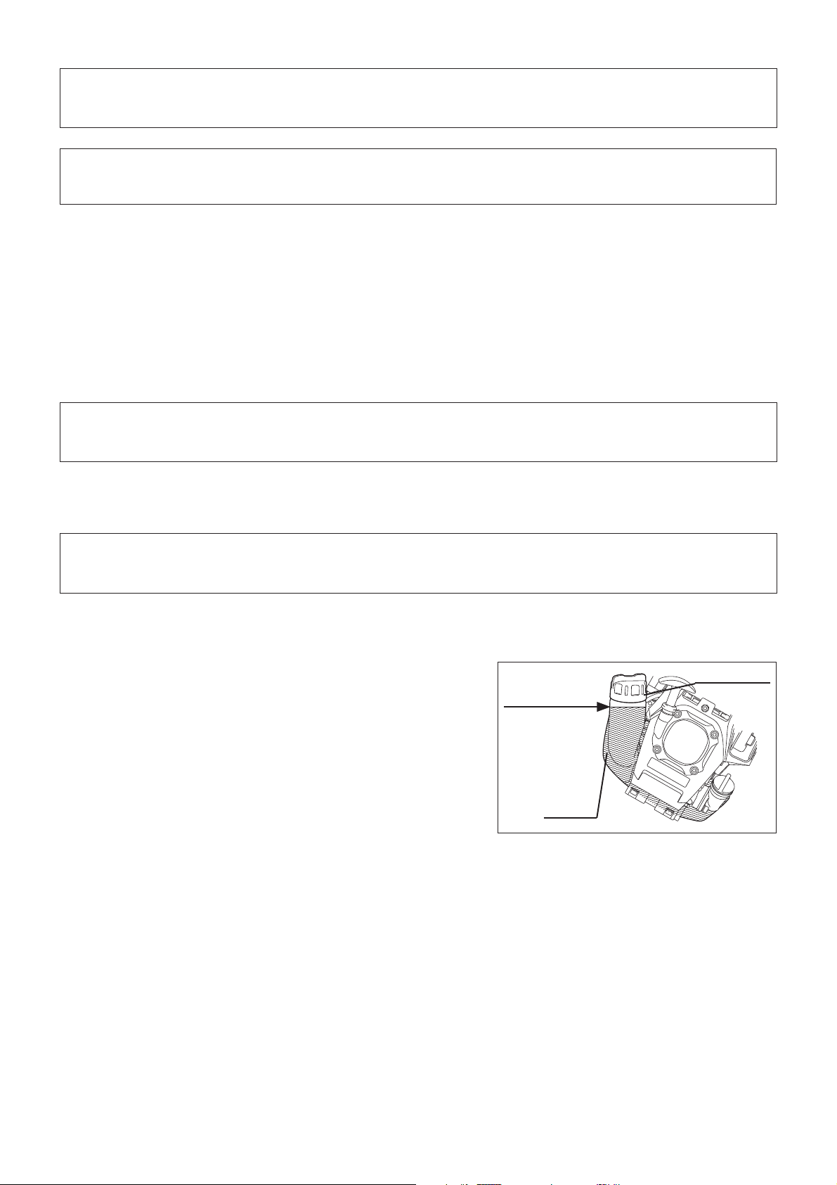
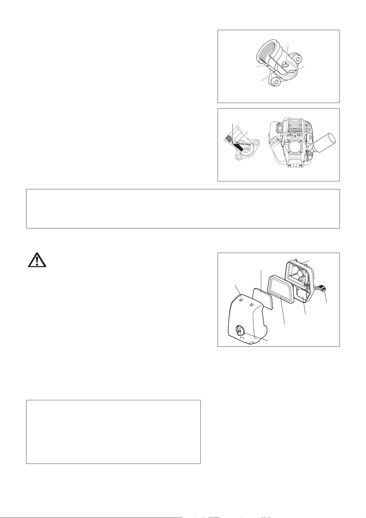
CLEANING OF AIR CLEANER
DANGER: INFLAMMABLES STRICTLY PROHIBITED
Interval of cleaning and inspection: Daily (every 10 operating hours)
Turn the choke lever to the full close side, and keep the carburetor off from dust or dirt.
Loosen the fixing bolt. Remove the air cleaner cover by pulling its bottom side. Remove the elements and tap them to remove dirt. If the elements are heavily contaminated: -
Remove the elements, immerse them in warm water or in water-diluted
neutral detergent, and dry them completely. Do not squeeze or rub them
when washing.
Before attaching the elements, be sure to dry them completely. Insufficient drying of the elements may lead to difficult startup.
Wipe out oil adhering around the air cleaner cover and the breather part with waste cloth.
Fit the element (sponge) into the element (felt). Fit the elements into the plate so that the sponge faces the air cleaner cover.
Immediately attach the cleaner cover and tighten it with fixing bolts. (In remounting, first place the upper claw, and then the lower claw.)
NOTICE:
Clean the elements several times a day, if excessive dust adheres to it. Dirty elements reduce engine power and make starting engine difficult.
Remove oil on the elements. If operation continues with the elements remaining not cleared of oil, oil in the air cleaner may fall outside, resulting
in contamination of the environment.
Do not put the elements on the ground or dirty place. Otherwise they pick up dirt or debris and it may damage the engine.
Never use fuel for cleaning the elements. Fuel may damage them. -
Plate
Element (sponge)
Air cleaner
cover
Choke
lever
Breather part
Element (felt)
Fixing bolt
18
Page 19
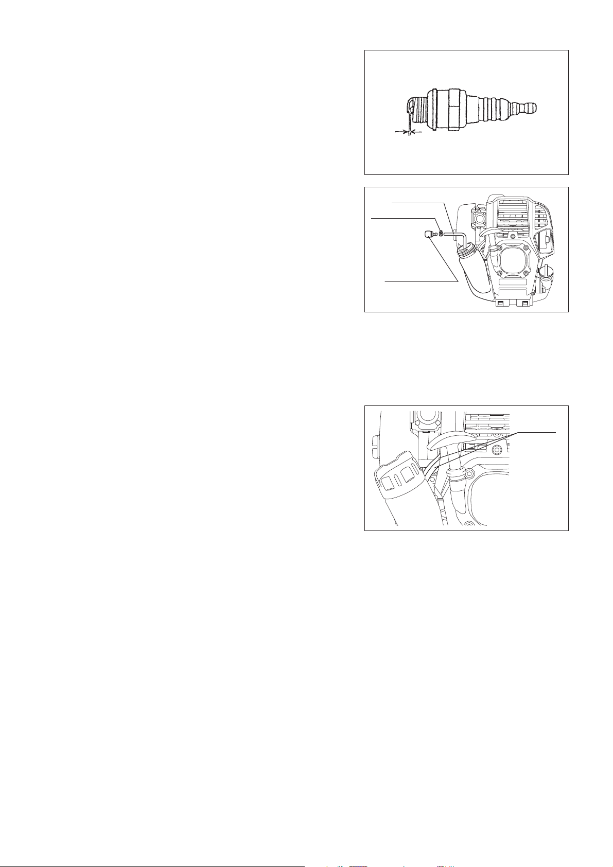
CHECKING THE SPARK PLUG
Only use the supplied universal wrench to remove or to install the spark plug. The gap between the two electrodes of the spark plug should be 0.7 - 0.8 mm -
(0.028” - 0.032”). If the gap is too wide or too narrow, adjust it. If the spark
plug is clogged or contaminated, clean it thoroughly or replace it.
CAUTION: Never touch the spark plug connector while the engine is running
(danger of high voltage electric shock).
CLEANING OF FUEL FILTER
WARNING: INFLAMMABLES STRICTLY PROHIBITED
Interval of cleaning and inspection: Monthly (every 50 operating hours)
Suction head in the fuel tank
Check the fuel filter periodically. To check the fuel filter, follow the steps below.
(1) Remove the fuel tank cap, drain the fuel to empty the tank. Check the tank
inside for any foreign materials. If any, remove them.
(2) Pull out the suction head by using a wire hook through the tank opening.
(3) If the fuel filter clogged slightly, clean it. To clean it, gently shake and tap
it in fuel. To avoid damage, do not squeeze or rub it. The fuel used for the
cleaning must be disposed in accordance with the method specified by
regulations in your country.
If the fuel filter became hard or heavily clogged up, replace it.
(4) After checking, cleaning or replacing, push the fuel filter in all the way to the
bottom of the fuel tank.
Clogged or damaged fuel filter can cause insufficient fuel supply and reduce
engine power. Replace the fuel filter at least quarterly to ensure satisfactory fuel
supply to the carburetor.
REPLACEMENT OF FUEL PIPE
CAUTION: INFLAMMABLES STRICTLY PROHIBITED
Interval of cleaning and inspection: Daily (every 10 operating hours)
Replacement: Annually (every 200 operating hours)
Replace the fuel pipe every year, regardless of operating frequency. Fuel
leakage may lead to fire.
If any leakage is detected during inspection, replace the fuel pipe immediately.
0.7 mm - 0.8 mm
(0.028” - 0.032”)
Fuel pipe
Hose clamp
Fuel filter
Fuel pipe
INSPECTION OF BOLTS, NUTS AND SCREWS
Retighten loose bolts, nuts, etc. Check for fuel and oil leakage. Replace damaged parts with new ones for safety operation. -
CLEANING OF PARTS
Keep the engine always clean. Keep the cylinder fins free of dust or dirt. Dust or dirt adhering to the fins will -
cause piston seizure.
REPLACEMENT OF GASKETS AND PACKINGS
In reassembling after the engine is dismounted, be sure to replace the gaskets and packings with new ones.
Any maintenance of adjustment work that is not included and described in this manual is only to be performed by Authorized Service Agents.
19
Page 20
STORAGE
WARNING: When draining the fuel, be sure to stop the engine and confirm that the engine cools
down.
Just after stopping the engine, it may still hot with possibility of burns, inflammability
and fire.
ATTENTION: When the machine is kept out of operation for a long time, drain up all fuel from the
fuel tank and carburetor, and keep it at a dry and clean place.
Drain up fuel from the fuel tank and carburetor according to the following procedure:
1) Remove the fuel tank cap, and drain fuel completely.
If there is any foreign matter remaining in the fuel tank, remove it
completely.
2) Pull out the fuel filter from the refill port using a wire.
3) Push the primer pump until fuel is drained from there, and drain fuel
coming into the fuel tank.
4) Reset the filter to the fuel tank, and securely tighten the fuel tank cap.
5) Then, continue to operate the engine until it stops.
Remove the spark plug, and drip several drops of engine oil through the spark plug hole.
Gently pull the starter handle so that engine oil will spread over the engine, and attach the spark plug.
Do not move the lever in the lock position while not mounting the attachment. The lever in the lock position without the attachment being mounted does not
allow the pole shaft of the attachment to be mounted.
During storage, keep the rod horizontal or keep the machine upright with the joint edge oriented upward. (In this case, pay full attention to prevent the
machine from falling.)
Never store the machine with the joint oriented downward. Lubricating oil may
spill out.
Keep the drained fuel in a special container in a well-ventilated shade. -
Drain fuel
Humidity
Attention after long-time storage
Before startup after long-time shutdown, be sure to replace oil (refer to P 17). Oil will deteriorate while the machine is kept out of operation. -
Fault location
Fault System Observation Cause
Engine not starting or with
difficulty
Warm start problems Tank filled ignition spark
Engine starts but dies Fuel supply Tank filled Incorrect idling adjustment, carburetor contaminated
Ignition system Ignition spark O.K. Fault in fuel supply or compression system, mechanical
defect
No ignition spark STOP-switch operated, wiring fault or short circuit, spark
plug or connector defective, ignition module faulty
Fuel supply Fuel tank filled Incorrect choke position, carburetor defective, fuel supply
line bent or blocked, fuel dirty
Compression No compression when
pulled over
Mechanical fault Starter not engaging Broken starter spring, broken parts inside of the engine
existing
Cylinder bottom gasket defective, crankshaft seals
damaged, cylinder or piston rings defective or improper
sealing of spark plug
Carburetor contaminated, have it cleaned
Fuel tank vent defective, fuel supply line interrupted,
cable or STOP-switch faulty
Insufficient performance Several systems may
simultaneously be
affected
Engine idling poor Air filter contaminated, carburetor contaminated, muffler
clogged, exhaust duct in the cylinder clogged
20
Page 21

Item
Operating time
Before
operation
After
lubrication
Daily
(10h)
30h 50h 200h
Shutdown/
rest
Corres-
ponding P
Engine oil
Inspect/clean
Replace
Tightening parts
(bolt, nut)
Inspect
Clean/inspect
Fuel tank
Drain fuel
Throttle lever Check function
Stop switch Check function
Low-speed rotation Inspect/adjust
Air cleaner Clean
Ignition plug Inspect
Cooling air duct Clean/inspect
Inspect
Fuel pipe
Replace
Fuel filter Clean/replace
Clearance between air intake
valve and air discharge valve
Adjust
Engine overhaul
Carburetor Drain fuel
13
1
*
17
19
—
3
*
20
—
16
16
18
19
19
19
2
*
—
19
2
*
2
*
3
*
—
—
20
*1 Perform initial replacement after 20h operation.
*2 For the 200 operating hour inspection, request Authorized Service Agent or a machine shop.
*3 After emptying the fuel tank, continue to run the engine and drain fuel in the carburetor.
Check instruction manuals for each attachment, and carry out maintenance on them when they are being used.
21
Page 22

TROUBLESHOOTING
Before making a request for repairs, check a trouble for yourself. If any abnormality is found, control your machine according to the description
of this manual. Never tamper or dismount any part contrary to the description. For repairs, contact Authorized Service Agent or local dealership.
State of abnormality Probable cause (malfunction) Remedy
Failure to operate primer pump Push 7 to 10 times
Low pulling speed of starter rope Pull strongly
Lack of fuel Feed fuel
Clogged fuel filter Clean
Broken fuel tube Straighten fuel tube
Deteriorated fuel Deteriorated fuel makes starting more difficult.
Replace with new one. (Recommended
replacement: 1 month)
Excessive suction of fuel Set throttle lever from medium speed to high
speed, and pull starter handle until engine
starts. Once engine starts, attachment
Engine does not start
Engine stops soon
Engine speed does not increase
Attachment does not rotate or move
Detached plug cap Attach securely
Contaminated spark plug Clean
Abnormal clearance of spark plug Adjust clearance
Other abnormality of spark plug Replace
Abnormal carburetor Make request for inspection and maintenance.
Starter rope cannot be pulled Make request for inspection and maintenance.
Abnormal drive system Make request for inspection and maintenance.
Insufficient warm-up Perform warm-up operation
Choke lever is set to “CLOSE” although
engine is warmed up.
Clogged fuel filter Clean or replace
Contaminated or clogged air cleaner Clean
Abnormal carburetor Make request for inspection and maintenance.
Abnormal drive system Make request for inspection and maintenance.
Attachment not inserted to the specified point. Insert as instructed.
starts rotating or moving. Pay full attention
to attachment.
If engine will not start still, remove spark plug,
make electrode dry, and reassemble them as
they originally are. Then, start as specified.
Set to “OPEN”
Stop engine immediately
Main unit vibrates abnormally Attachment not inserted to the specified point. Insert as instructed.
Stop engine immediately
Attachment does not stop immediately High idling rotation Adjust
Stop engine immediately
Engine does not stop Detached connector Attach securely
Run engine at idling, and set choke lever
to CLOSE
When the engine does not start after warm-up operation:
If there is no abnormality found for the check items, open the throttle by about 1/3 and start the engine.
Abnormal drive system Make request for inspection and maintenance.
Loosened lever Tighten securely.
Abnormal drive system Make request for inspection and maintenance.
Detached throttle wire Attach securely
Abnormal drive system Make request for inspection and maintenance.
Abnormal electric system Make request for inspection and maintenance.
22
Page 23
Français
(Instructions d’origine)
Merci beaucoup d’avoir choisi cet outil multi-fonctions MAKITA. Nous sommes
ravis de vous recommander l’outil multi-fonctions de MAKITA, résultat d’un long
programme de développement et de nombreuses années d’expérience et de
connaissances.
Veuillez lire ce livret qui explique en détails les nombreuses caractéristiques qui
en font un outil d’une performance exceptionnelle. Elles vous aideront à obtenir
les meilleurs résultats possibles de votre outil multi-fonctions MAKITA.
SYMBOLES
Le mode d’emploi contient les symboles suivants.
Lisez le mode d’emploi et suivez les
avertissements et les précautions de
sécurité !
Table des matières Page
Symboles .....................................................................23
Consignes de sécurité .................................................24
Données techniques ....................................................28
Pièces de fixation agréées ..........................................29
Nomenclature des pièces ............................................30
Montage de la poignée ................................................31
Montage de la pièce de fixation ...................................31
Démontage ..................................................................32
Avant de commencer ................................................... 33
Maniement correct de la machine ...............................35
Avertissement de fonctionnement et comment
l’arrêter ........................................................................35
Instructions d’entretien ................................................38
Entreposage ................................................................41
Portez un casque protecteur, des lunettes
de protection et des protège-oreilles !
Faites preuve de prudence et de
vigilance !
Interdit ! Démarrage manuel du moteur
Ne fumez pas ! Arrêt d’urgence
Pas de flammes nues ! Premiers secours
Portez des gants de protection ! SOUS TENSION/DÉMARRAGE
Portez des bottes de sécurité avec des
semelles antidérapantes.
Les bottes de sécurité à doigts de pieds
métalliques sont recommandées !
Carburant (Essence)
HORS TENSION/ARRÊT
Éloignez les personnes et les animaux du
lieu de travail !
23
Page 24
Utilisation prévue de l’outil
Cet outil multi-fonctions est destiné à insérer un accessoire approuvé indiqué
dans ce mode d’emploi. N’utilisez jamais l’appareil à d’autres fins.
CONSIGNES DE SÉCURITÉ
Instructions générales
Pour une utilisation correcte, lisez ce mode d’emploi afin de vous familiariser avec le fonctionnement de l’outil multi-fonctions. Sans ces informations, vous
risquez de vous mettre en danger ou de blesser d’autres personnes à cause
d’une utilisation incorrecte.
Il est recommandé de prêter l’outil multi-fonctions uniquement à des personnes ayant déjà utilisé des outils multi-fonctions.
Transmettez-leur toujours ce mode d’emploi.
Les personnes utilisant l’outil pour la première fois doivent demander au revendeur de leur fournir des instructions de base afin de se familiariser avec
le maniement d’une découpeuse thermique.
Les enfants et jeunes gens âgés de moins de 18 ans ne doivent pas utiliser l’outil multi-fonctions. Toutefois, les personnes âgées de plus de 16 ans
peuvent utiliser l’appareil à des fins de formation uniquement sous la
supervision d’un formateur qualifié.
Utilisez les outils multi-fonctions avec la plus grande prudence et vigilance. Faites fonctionner l’outil multi-fonctions uniquement si vous êtes en bonne -
forme physique. Effectuez tout le travail avec calme et prudence. Vous êtes
responsable des autres personnes.
N’utilisez jamais l’outil multi-fonctions après avoir consommé de l’alcool ou des médicaments, ou bien si vous vous sentez fatigué (e) ou malade.
Les réglementations nationales peuvent limiter l’utilisation de l’appareil. -
Dispositif de protection individuelle
Les vêtements que vous portez doivent être fonctionnels et adaptés, c’est-à-dire qu’ils doivent être près du corps, sans pour autant gêner vos
mouvements. Ne portez pas de bijoux ou de vêtements qui pourraient
s’emmêler dans les taillis ou les petits arbustes.
Pour éviter de vous blesser à la tête, aux yeux, aux mains ou aux pieds et pour protéger votre ouïe pendant l’utilisation de l’outil multi-fonctions, portez
l’équipement et les vêtements de protection suivants.
Portez toujours un casque en cas de risque de chute d’objets. Le casque de protection (1) doit être vérifié à intervalles réguliers pour parer à d’éventuels
dommages et il doit être remplacé au plus tard tous les 5 ans. N’utilisez que
des casques de protection agréés.
La visière (2) du casque (ou alternativement les lunettes) protège le visage des débris et des pierres qui volent. Pendant l’utilisation de l’outil multifonctions, portez toujours des lunettes de protection ou une visière pour
protéger vos yeux des blessures.
Portez un équipement de protection antibruit adéquat afin d’éviter toute perte auditive (coquilles antibruit (3), bouchons d’oreille etc.).
Les combinaisons de travail (4) protègent contre les pierres et débris qui volent.
Il est fortement recommandé de porter une combinaison de travail.
Les gants spéciaux (5) en cuir épais font partie de l’équipement prescrit et doivent être portés lors de l’utilisation de l’outil multi-fonctions.
Portez également toujours des chaussures de sécurité (6) dotées d’une semelle antidérapante. Elles vous protègerons des blessures éventuelles et
vous assureront une bonne stabilité.
Démarrage de l’outil multi-fonctions
Assurez-vous qu’aucun enfant ou adulte ne se trouve à proximité et faites attention aux animaux situés dans la zone de travail.
Assurez-vous que la pièce de fixation est bien en place, que le levier de commande peut être actionné aisément et que le levier de verrouillage
fonctionne correctement.
Il est interdit de faire bouger la pièce de fixation pendant le ralenti. En cas de doute, vérifiez le réglage avec votre revendeur. Vérifiez que les poignées sont
propres et sèches et que l’interrupteur marche/arrêt fonctionne correctement.
Illustration
15 mètres
24
Page 25
Démarrez l’outil multi-fonctions uniquement conformément aux instructions.
Ne démarrez pas le moteur selon une autre méthode ! Utilisez l’outil multi-fonctions et les au tres outils uniquement pour les -
applications indiquées.
Ne démarrez le moteur de l’outil multi-fonctions qu’après avoir procédé au -
montage complet. Le fonctionnement de l’outil n’est autorisé qu’une fois
l’ensemble des accessoires fixés !
Avant de démarrer, assurez-vous que la pièce de fixation n’est pas en contact avec des objets durs, tels que des branches, des pierres, etc., car
elle tournera au démarrage.
En cas de problème avec le moteur, éteignez-le immédiatement. Si l’outil de coupe frappe des pierres ou d’autres objets durs, coupez -
immédiatement le moteur et examinez la pièce de fixation.
N’utilisez l’outil multi-fonctions qu’après avoir fixé et réglé correctement le -
harnais. Il est très important de régler le harnais selon votre taille, afin d’éviter
toute fatigue supplémentaire pendant l’utilisation. Ne tenez jamais l’outil
d’une seule main pendant l’utilisation.
Pendant l’utilisation, tenez toujours l’outil multi-fonctions avec les deux mains. Assurez-vous toujours d’avoir une bonne stabilité.
Faites fonctionner l’outil multi-fonctions de manière à éviter d’inhaler les gaz d’échappement. Ne faites jamais tourner le moteur dans une pièce confinée
(risque d’intoxication aux gaz). Le monoxyde de carbone est un gaz inodore.
Éteignez le moteur avant de faire une pause ou de laisser l’outil multi- fonctions sans surveillance. Placez-le également en lieu sûr pour éviter que
d’autres personnes se blessent ou endommagent l’appareil.
Ne posez jamais l’outil multi-fonctions dans l’herbe sèche ou sur des matériaux combustibles lorsqu’il est chaud.
Vous devez utiliser tous les carters et installations de protection fournis avec l’appareil pendant son fonctionnement.
Ne faites jamais tourner le moteur si le pot d’échappement est défectueux. Éteignez le moteur pendant le transport. En cas de transport sur de longues distances, utilisez toujours le dispositif de -
protection d’outil fourni.
Veillez à placer l’outil multi-fonctions de manière sécurisée pendant le -
transport en voiture afin d’éviter toute fuite de carburant.
Lors du transport de l’outil multi-fonctions, assurez-vous que le réservoir de -
carburant est complètement vide.
Lors du déchargement de - l’outil multi-fonctions depuis un véhicule, veillez
à ne pas laisser tomber le moteur au risque d’endommager grièvement le
réservoir de carburant.
Sauf en cas d’urgence, ne laissez jamais tomber l’outil multi-fonctions et ne le jetez pas au sol, au risque de l’endommager grièvement.
Veillez à soulever l’ensemble du matériel du sol lorsque vous le déplacez. Il est très dangereux de traîner le réservoir de carburant : cela risque de créer
des fuites de carburant, voir un incendie.
En cas de chute ou d’impact de l’appareil, vérifiez qu’il est en bon état avant de poursuivre le travail. Vérifiez qu’il n’y a pas de fuite de carburant dans
le circuit d’alimentation, et que les commandes et dispositifs de sécurité
fonctionnent correctement. En cas de dommage ou de doute, demandez à un
centre d’entretien agréé d’examiner et de réparer l’outil.
• Au repos
• Transport
• Ravitaillement en carburant
• Entretien
• Remplacement d’outil
Ravitaillement en carburant
Lors du ravitaillement en carburant, coupez le moteur, éloignez-le des flammes nues et ne fumez pas.
Évitez tout contact entre la peau et l’essence. N’inhalez pas les vapeurs de carburant. Portez toujours des gants de protection durant le ravitaillement en
carburant. Changez et nettoyez régulièrement les vêtements de protection.
Veillez à ne pas renverser de carburant ou d’huile, afin d’éviter toute contamination du sol (protection environnementale). Si vous avez renversé
du carburant, nettoyez immédiatement l’outil multi-fonctions.
Évitez tout contact entre vos vêtements et le carburant. Si vous renversez du carburant sur vos vêtements, changez-en immédiatement (pour éviter que
vos vêtements ne prennent feu).
Vérifiez régulièrement le bouchon du réservoir pour vous assurer qu’il est bien fermé et ne fuit pas.
Serrez soigneusement le bouchon du réservoir de carburant. Déplacez-vous pour démarrer le moteur (à au moins 3 mètres de l’endroit où vous avez fait
le plein).
Ne faites jamais le plein dans une pièce confinée. Les vapeurs de carburant s’accumulent au niveau du sol (risques d’explosions).
Transportez et stockez le carburant uniquement dans des conteneurs agréés. Assurez-vous que les enfants ne peuvent pas accéder au carburant.
25
3 mètres
Page 26
Mode d’emploi
Utilisez l’outil multi-fonctions uniquement lorsque l’éclairage est correct et la visibilité satisfaisante. Pendant l’hiver, soyez attentif aux zones glissantes
ou mouillées, au verglas et à la neige (risques de glissade). Assurez-vous
toujours d’avoir une bonne stabilité.
N’utilisez jamais l’outil multi-fonctions lorsque vous vous trouvez sur une échelle.
N’utilisez jamais l’outil multi-fonctions lorsque vous trouvez dans un arbre. Ne travaillez jamais sur des surfaces instables. Avant d’utiliser la pièce de fixation, veillez à ce que celle-ci ait atteint sa -
vitesse maximale.
Reposez-vous pour éviter toute perte de contrôle due à la fatigue. Il est -
recommandé de faire une pause de 10 à 20 minutes toutes les heures.
Instructions d’entretien
L’entretien de votre appareil doit être effectué par l’un de nos centres d’entretien agréés et seules des pièces de rechange authentiques doivent
être utilisées. Une réparation incorrecte et un entretien défectueux peuvent
réduire la durée de vie de l’appareil et accroître le risque d’accidents.
Veillez à faire le moins de bruit possible et à limiter la contamination lors de l’utilisation de l’outil multi-fonctions. Vérifiez notamment le bon réglage du
carburateur.
Nettoyez régulièrement l’outil multi-fonctions et vérifiez que toutes les vis ainsi que les écrous sont bien serrés.
Ne procédez jamais à l’entretien de l’outil multi-fonctions et ne le stockez pas à proximité de flammes nues.
Toujours rangez l’outil multi-fonctions dans des pièces fermées, après avoir vidé le réservoir de carburant.
Observez les instructions de prévention d’accident pertinentes publiées par les associations commerciales et les compagnies d’assurance.
N’effectuez aucune modification sur l’outil multi-fonctions, au risque de compromettre votre sécurité.
L’exécution de l’entretien ou des réparations par l’utilisateur est limitée aux activités décrites dans le mode d’emploi. Toute autre tâche doit être
réalisée par un agent d’entretien agréé. N’utilisez que des pièces de rechange et des accessoires d’origine fournis par MAKITA.
L’utilisation d’accessoires ou d’outils non approuvés augmente les risques d’accident.
MAKITA n’acceptera aucune responsabilité pour des accidents ou des dommages causés par l’utilisation de pièces de fixation et de dispositifs
de fixation de pièces de fixation ou d’accessoires non agréés.
Premiers secours
En cas d’accident, assurez-vous qu’une mallette de premier secours se trouve
à proximité des opérations de coupe. Remplacez immédiatement tout article
pris dans la mallette de premier secours.
Lorsque vous demandez de l’aide, veuillez fournir les
renseignements suivants :
Lieu de l’accident Que s’est-il passé ? Nombre de personnes blessées Types de blessures Votre nom -
Vibrations
Les personnes souffrant de troubles circulatoires peuvent subir des blessures au niveau des vaisseaux sanguins ou du système nerveux si elles sont exposées à des vibrations excessives. Les vibrations peuvent entraîner les symptômes suivants aux doigts, mains ou poignets :
engourdissement, picotements, douleur, sensation lancinante, altération de la couleur ou de l’aspect de la peau. Si l’un ou l’autre de ces
symptômes apparaît, consultez un médecin !
Afin de réduire le risque de syndrome des vibrations du système main-bras, gardez vos mains au chaud et maintenez correctement l’appareil et ses accessoires.
26
Page 27

DÉCLARATION DE CONFORMITÉ CE
Nous, Makita Corporation, en tant que fabricant responsable, déclarons que les machines Makita suivantes :
Nom de la machine : Outil Multi-Fonctions
N° de modèle/Type : EX2650LH
Spécifications : voir le tableau « DONNÉES TECHNIQUES EX2650LH »
sont fabriquées en série et
sont conformes aux directives européennes suivantes :
2000/14/CE, 2006/42/CE
et sont produites conformément aux normes ou documents de normalisation suivants :
EN/ISO11806, EN709, EN/ISO10517, EN/ISO11680, EN/ISO12100
La documentation technique est disponible auprès de :
Makita International Europe Ltd., Technical Department,
Michigan Drive, Tongwell,
Milton Keynes, Bucks MK15 8JD, Angleterre
La procédure d’évaluation de la conformité requise par la directive 2000/14/CE est conforme à l’annexe V.
EX2650LH avec EM400MP (Tête Débroussailleuse)
EX2650LH avec EM401MP (Tête Débroussailleuse)
EX2650LH avec ER400MP (Tête Coupe Herbe)
EX2650LH avec EN400MP (Tête Taille-Haie à Perche)
EX2650LH avec EN400MP (Tête Taille-Haie à Perche) et LE400MP (Rallonge d’Arbre)
Niveau de puissance sonore mesurée : 108,5 dB (A)
Niveau de puissance sonore garantie : 113 dB (A)
Niveau de puissance sonore mesurée : 102,7 dB (A)
Niveau de puissance sonore garantie : 105 dB (A)
Niveau de puissance sonore mesurée : 109,2 dB (A)
Niveau de puissance sonore garantie : 116 dB (A)
Niveau de puissance sonore mesurée : 103,8 dB (A)
Niveau de puissance sonore garantie : 109 dB (A)
Niveau de puissance sonore mesurée : 104,0 dB (A)
Niveau de puissance sonore garantie : 106 dB (A)
Le numéro du certificat d’inspection de type CE comme une scie à long manche avec EY400MP, EY401MP, LE400MP est :
4811004.11016
L’inspection de type CE pour la norme 2006/42/CE a été réalisée par :
DEKRA Testing and Certification GmbH
Enderstraße 92b
01277 Dresden, Allemagne
N° d’identification 2140
30. 1. 2012
Tomoyasu Kato
Directeur
Makita Corporation
3-11-8, Sumiyoshi-cho,
Anjo, Aichi, 446-8502, JAPAN
27
Page 28

DONNÉES TECHNIQUES EX2650LH
Modèle
EX2650LH
Poignée fermée
Dimensions : longueur x largeur x hauteur (sans la lame de
coupe) avec garde-fou
Dimensions : longueur x largeur x hauteur (sans la lame de
coupe) sans garde-fou
mm 975 x 323 x 241
mm 975 x 242 x 241
Masse (sans la protection plastique et la lame de coupe) kg 4,6
Volume (réservoir de carburant) L 0,6
Volume (réservoir d’huile) L 0,08
Déplacement du moteur cm
3
Performance maximale du moteur kw 0,77 à 7 000 min
Vitesse du moteur à la vitesse max. recommandée de l’axe min
Vitesse maximale de l’axe (correspondant) min
-1
-1
25,4
-1
8 500
6 500
Consommation maximale de carburant kg/h 0,33
Consommation maximale spécifique de carburant g/kwh 408
Ralenti min
Vitesse d’engagement de l’embrayage min
-1
-1
3 000
3 900
Carburateur type WALBRO WYL
Système d’allumage type Allumage à semi-conducteur
Bougie d’allumage type NGK CMR4A
Distance entre les électrodes mm 0,7 - 0,8
Carburant Essence automobile
Huile moteur
Classe SF ou supérieure (moteur 4 temps pour automobile)
Huile SAE 10W-30 de classe API,
Vibrations
Tête a
Poignée droite (prise arrière) Poignée gauche (prise avant)
(m/s2) Incertitude K (m/s2)a
hv eq
(m/s2) Incertitude K (m/s2)
hv eq
Normes
applicables
EM400MP 6,5 1,2 5,9 1,8 ISO 22867
EM401MP 5,6 2,1 4,8 1,0 ISO 22867
ER400MP 7,1 2,8 5,5 2,7 ISO 22867
EY400MP 9,4 2,0 4,2 2,0 ISO 22867
EY400MP + LE400MP 4,8 2,0 3,4 2,0 ISO 22867
EY401MP 6,5 2,0 3,8 2,0 ISO 22867
EY401MP + LE400MP 5,6 2,0 3,4 2,0 ISO 22867
EN400MP 8,4 1,8 5,0 0,7 ISO 10517
EN400MP + LE400MP 8,0 1,7 4,3 0,7 ISO 10517
KR400MP 5 1,1 4,4 2,3 ISO 22867
EJ400MP 7,1 1,5 4,9 1,5 ISO 22867
EJ400MP + LE400MP 6,4 0,6 4,0 0,7 ISO 22867
28
Page 29

Bruit
Moyenne du niveau de pression sonore Moyenne du niveau de puissance sonore
Tête L
PA eq
Incertitude K L
WA eq
Incertitude K
Normes
applicables
EM400MP 95,0 4,4 105,5 3,3 ISO 22868
EM401MP 89,9 3,6 99,7 2,7 ISO 22868
ER400MP 97,9 4,2 106,2 4,0 ISO 22868
EY400MP 93,0 2,5 104,5 2,5 ISO 22868
EY400MP + LE400MP 90,3 2,5 107,8 2,5 ISO 22868
EY401MP 92,6 2,5 104,7 2,5 ISO 22868
EY401MP + LE400MP 90,5 2,5 107,9 2,5 ISO 22868
EN400MP 93,1 4,4 102,9 4,8 ISO 10517
EN400MP + LE400MP 87,8 1,9 103,0 2,0 ISO 10517
KR400MP 93,7 2,6 99,7 1,2 ISO 22868
EJ400MP 89,0 2,3 99,8 1,1 ISO 22868
EJ400MP + LE400MP 88,1 2,2 100,8 2,3 ISO 22868
PIÈCES DE FIXATION AGRÉÉES
PIÈCES DE FIXATION Modèles
Tête Débroussailleuse EM400MP, EM401MP
Tête Coupe Herbe ER400MP
Tête Élagueuse à Perche EY400MP, EY401MP
Tête Taille-Haie à Perche EN400MP
Tête Moto-Bineuse KR400MP
Tête Peigne Vibreur Pour Café EJ400MP
Rallonge d’Arbre LE400MP
29
Page 30
NOMENCLATURE DES PIÈCES
EX2650LH
6
14
7
12
11
10
4
8
9
18
13
15
3
5
16
17
1
2
F NOMENCLATURE DES PIÈCES
1 Réservoir de carburant
2 Démarreur à rappel
3 Filtre à air
4 Interrupteur I-O (marche/arrêt)
5 Pot d’échappement
6 Carter d’embrayage
7 Prise arrière
8 Crochet de suspension
9 Poignée
10 Levier d’accélération
11 Levier de verrouillage
12 Câble de contrôle
13 Arbre
14 Bouchon de réservoir de carburant
15 Bouton de démarrage
16 Tuyau d’échappement
17 Bouchon d’huile
18 Garde-fou*
Remarque : Dans certains pays, le garde-fou
n’est pas fourni avec l’outil.
30
Page 31

MONTAGE DE LA POIGNÉE
ATTENTION : Avant tout travail sur l’outil multi-fonctions, coupez toujours le
moteur et débranchez le connecteur des bougies.
Portez toujours des gants de protection !
ATTENTION : Démarrez l’outil multi-fonctions uniquement après l’avoir
entièrement monté.
Montage de la poignée fermée
Installez solidement le garde-fou et la commande sur le tuyau de l’arbre à l’aide de deux vis et colliers. À ce stade, placez le garde-fou sur le côté
gauche de l’appareil, comme illustré.
Assurez-vous que l’ensemble commande/garde-fou ne se trouve pas entre l’entretoise et le repère flèche. Ne retirez pas et ne contractez pas
l’entretoise.
Une fois le montage terminé, ne retirez pas le garde-fou. -
ATTENTION : N’installez jamais la commande sur l’étiquette ou le joint.
Remarque : Dans certains pays, le garde-fou et le repère flèche ne sont pas
fournis avec l’outil.
MONTAGE DE LA PIÈCE DE FIXATION
ATTENTION : Avant tout travail sur l’outil multi-fonctions, coupez toujours le
moteur et débranchez le connecteur des bougies.
Portez toujours des gants de protection !
ATTENTION : Démarrez l’outil multi-fonctions uniquement après l’avoir
entièrement monté.
Montage
Dévissez le levier. Alignez l’axe de la pièce de fixation sur la rainure du joint et insérez l’axe. Insérez la pièce de fixation jusqu’à la position de la pièce de fixation -
représentée par une flèche.
Vérifiez également que le bouton est monté.
Serrez le levier. (pour obtenir des instructions de montage, voir le schéma à droite.)
Repère
flèche
Moteur
Joint
31
Page 32

DÉMONTAGE
Dévissez le levier. Appuyez sur le bouton et sortez la pièce de fixation de la porte. -
(Dans la mesure du possible, essayez de sortir la pièce de fixation en ligne
droite.)
Remarque :
Ne laissez pas le levier serré lorsque la pièce de fixation est retirée. -
32
Page 33

AVANT DE COMMENCER
Inspection et remplissage de l’huile moteur
Procédez comme suit, lorsque le moteur est froid. Réglez le niveau du moteur, retirez le bouchon d’huile (Fig. 1) et vérifiez l’absence d’huile dans la plage comprise entre les repères des -
limites supérieure et inférieure du tuyau d’huile (Fig. 2).
Si la quantité d’huile est insuffisante (le niveau d’huile est proche du repère de limite intérieure) (Fig. 3), remplissez d’huile jusqu’au repère de -
limite supérieure.
La zone proche des repères externes est transparente, dont la quantité d’huile à l’intérieur peut être vérifiée sans qu’il soit nécessaire de -
retirer le bouchon d’huile. Toutefois, si le tuyau d’huile devient extrêmement encrassé, vous risquez d’avoir une mauvaise visibilité et de
devoir vérifier le niveau d’huile par rapport à la section décrochée sur l’intérieur du tuyau d’huile.
À titre d’information, la durée de remplissage de l’huile est de 10 heures environ (tous les 10 remplissages). Si l’huile change de couleur ou contient de la saleté, remplacez-la. (Pour la fréquence et la méthode de vidange, référez-vous à la page 38)
Huile recommandée : Huile SAE 10W-30 de classe API Classification, Classe SF ou supérieure (moteur 4 temps pour automobile)
Volume d’huile : Environ 0,08 L
Remarque : Si le moteur n’est pas maintenu en position verticale, la quantité d’huile versée risque d’être trop importante et l’huile risque de
pénétrer à l’intérieur du moteur.
Si l’huile est ajoutée au-delà de la limite, elle risque d’être contaminée ou de déclencher un incendie avec de la fumée blanche.
Point n°1 du remplacement de l’huile : « bouchon d’huile »
Retirez la poussière ou les saletés entourant l’orifice du réservoir d’huile, puis retirez le bouchon d’huile. Veillez à ce que le bouchon d’huile n’entre pas en contact avec du sable ou de la poussière. Dans le cas contraire, les impuretés -
adhérant au bouchon d’huile pourraient empêcher la bonne circulation de l’huile ou abimer des pièces du moteur, ce qui provoquerait des
problèmes.
Huile
Repère externe
(limite supérieure)
Bouchon d’huile
Section interne
décrochée (limite
supérieure)
Tuyau
d’huile
Fig. 1
(1) Gardez le moteur à plat et enlevez le bouchon d’huile.
Section interne
décrochée
(limite inférieure)
Fig. 2 Tuyau d’huile Fig. 3
Repère
externe
(limite
inférieure)
Remplissez d’huile
jusqu’à ce que
le niveau d’huile
atteigne la section
décrochée (limite
supérieure).
La zone située entre
les limites externes
supérieure et inférieure
est transparente, donc le
niveau d’huile peut être
vérifié à l’extérieur par
rapport à ces repères.
(2) Remplissez d’huile jusqu’au repère de limite supérieure. (voir Fig. 3)
Utilisez la bouteille d’huile lors du remplissage.
(3) Serrez à fond le bouchon d’huile. Un vissage insuffisant pourrait provoquer
une fuite d’huile.
33
Page 34

Remarque
Ne remplacez pas l’huile lorsque le moteur est en position inclinée.•
Le remplissage d’huile avec le moteur incliné risque de provoquer un remplissage trop important, entraînant la contamination de l’huile et/•
ou de la fumée blanche.
Point n°2 du remplacement de l’huile : « En cas de débordement d’huile »
Si de l’huile se répand entre le réservoir de carburant et le bloc principal du moteur, elle risque d’être aspirée dans le port d’entrée de l’air de refroidissement, contaminant le moteur. Veillez à nettoyer l’huile qui a débordé avant toute utilisation.
RAVITAILLEMENT EN CARBURANT
Maniement du carburant
Veillez à manipuler le carburant avec la plus grande prudence. Il peut contenir des substances similaires aux solvants. Pour faire le plein,
placez-vous dans une pièce suffisamment ventilée ou à l’extérieur. N’inhalez jamais les vapeurs de carburant et restez à distance du carburant.
En cas de contact répété ou prolongé de votre peau avec du carburant, elle peut se dessécher et causer des maladies de peau ou des
allergies. En cas de contact du carburant avec un œil, rincez celui-ci à l’eau claire. Si votre œil reste irrité, consultez votre médecin.
Durée de stockage du carburant
Le carburant doit être utilisé dans les 4 semaines, même s’il est conservée dans un bidon spécial dans un endroit ombragé et bien ventilé.
Si vous n’utilisez pas de bidon spécial ou qu’il n’est pas fermé, le carburant peut se détériorer en une journée.
STOCKAGE DE LA MACHINE ET REMPLISSAGE DU RÉSERVOIR
Conservez la machine et le réservoir dans un endroit frais et abrité de la lumière directe du soleil. Ne conservez jamais le carburant dans un bungalow ou un coffre. -
Carburant
Le moteur est un moteur à quatre temps. Assurez-vous d’utiliser de l’essence pour automobile (super ou premium).
Avertissements concernant le carburant
N’utilisez jamais de mélange de carburant contenant de l’huile moteur. Cela pourrait créer une accumulation excessive de carbone ou des pannes mécaniques.
L’utilisation d’huile détériorée peut provoquer des démarrages irréguliers du moteur. -
Ravitaillement en carburant
AVERTISSEMENT : PRODUITS INFLAMMABLES STRICTEMENT
INTERDITS
Essence utilisée : Essence pour automobile (super sans plomb)
Dévissez légèrement le bouchon du réservoir afin qu’il n’y ait pas de différence de pression.
Retirez le bouchon du réservoir et remplissez le réservoir de carburant en l’inclinant de manière à en chasser l’air, l’orifice dirigé vers le haut. (Ne
remplissez jamais le réservoir de carburant jusqu’à ce qu’il déborde sur
l’orifice de remplissage d’huile.)
Essuyez bien le tour du bouchon du réservoir pour éviter l’introduction de tout corps étranger dans le réservoir de carburant.
Après avoir fait le plein, serrez à fond le bouchon du réservoir de carburant. -
En cas de défaut ou de dommages au bouchon du réservoir, remplacez-le.•
Le bouchon du réservoir est une pièce d’usure : il convient donc de le •
remplacer tous les deux à trois ans.
Limite supérieure
de carburant
Réservoir de
carburant
Bouchon du
réservoir de
carburant
34
Page 35

MANIEMENT CORRECT DE LA MACHINE
Fixation du harnais
Réglez le harnais en fonction de la longueur nécessaire à l’opération que vous allez effectuer.
Détachement
En cas d’urgence, appuyez sur les encoches (1) situées de chaque côté, puis retirez la machine en la tirant vers vous.
Veillez particulièrement à garder le contrôle de la machine à ce stade. Ne
laissez pas la machine être déviée vers vous ou vers quelqu’un qui se trouve
à proximité du lieu de travail.
AVERTISSEMENT : En perdant le contrôle de la machine, vous risquez
de provoquer des blessures corporelles graves ou
MORTELLES.
(1)
Crochet de
suspension
AVERTISSEMENT DE FONCTIONNEMENT ET COMMENT L’ARRÊTER
Respectez les législations de préventions d’accidents en vigueur !
DÉMARRAGE
Déplacez-vous d’au moins 3 mètres de l’endroit où vous avez procédé au ravitaillement en carburant. Déposez l’outil multi-fonctions dans un
endroit propre, en veillant à ce que l’outil de coupe n’entre pas en contact avec le sol ou tout autre objet.
A : Démarrage à froid
1) Déposez la machine sur une surface plane.
2) Réglez l’interrupteur I-O (1) sur FONCTIONNEMENT.
FONCTIONNEMENT
Levier de verrouillage
STOP
Levier d’accélération
(1)
Vitesse élevée
Basse vitesse
35
Page 36

3) Pompe d’amorçage
Continuez à appuyer sur la pompe d’amorçage jusqu’à ce que le carburant
pénètre dans la pompe d’amorçage.
(En général, le carburant pénètre dans la pompe d’amorçage après 7 à
10 pressions.)
Si vous appuyez trop sur la pompe d’amorçage, un surplus de carburant
retourne au réservoir de carburant.
4) Démarreur
Tirez doucement le bouton du démarreur, jusqu’à ce qu’il résiste (point de
compression). Ensuite, repoussez le bouton du démarreur, puis tirez-le
fortement.
Ne tirez jamais entièrement la corde. Une fois le bouton du démarreur tiré,
n’enlevez jamais votre main immédiatement. Tenez le bouton jusqu’à ce
qu’il retourne à sa position initiale.
5) Opération de chauffage
Continuez à faire chauffer le moteur pendant 2 à 3 minutes.
Pompe
d’amorçage
Carburateur
Remarque : Si une entrée de carburant excessive se produit, enlevez la bougie et tirez la poignée de démarrage lentement pour retirer l’excès
de carburant. Séchez également l’électrode de la bougie.
Attention durant le fonctionnement :
Si le levier d’accélération est complètement ouvert durant un fonctionnement à vide, la rotation du moteur augmente à 10 000 min-1 ou plus. Ne
jamais faire tourner le moteur à une vitesse plus élevée que nécessaire, ou à une vitesse de 6 000 à 8 500 min
-1
environ.
B : Démarrage après avoir fait chauffer le moteur
1) Appuyez plusieurs fois sur la pompe d’amorçage.
2) Laissez le levier d’accélération en position de ralenti.
3) Tirez avec force sur le démarreur.
4) Si le moteur est difficile à démarrer, ouvrez les gaz d’environ 1/3.
Faites attention à la pièce de fixation, qui pourrait tourner.
Parfois, notamment en hiver, lorsque le démarrage
FERMER
du moteur est difficile
Actionnez le levier de l’étrangleur comme suit lors du démarrage du moteur.
Après avoir exécuté les étapes de démarrage 1) à 3), placez le levier de •
l’étrangleur en position FERMER.
Exécutez l’étape 4) et démarrez le moteur.•
Lorsque le moteur démarre, réglez le levier d’étrangleur en position OUVRIR.•
Exécutez l’étape de démarrage 5) et continuez à vous échauffer.•
ATTENTION : Si bang (bruit d’explosion) est entendu et si le moteur s’arrête, ou
si le moteur que vous venez de démarrer cale avant que le levier
d’étrangleur soit utilisé, replacez le levier d’étrangleur en position
OUVRIR, puis tirez plusieurs fois sur le bouton du démarreur
pour démarrer le moteur.
ATTENTION : Si le levier d’étrangleur est maintenu en position FERMER et si le
bouton d’étrangleur est enfoncé plusieurs fois, une quantité trop
importante de carburant sera aspirée et le démarrage du moteur
deviendra difficile.
36
OUVRIR
Page 37

ARRÊT
1) Relâchez entièrement le levier d’accélération (2) et lorsque la vitesse de
rotation du moteur a diminué, placez l’interrupteur I-O en position STOP
pour couper le moteur.
2) N’oubliez pas que la pièce de fixation peut ne pas s’arrêter immédiatement,
laissez-la ralentir jusqu’à l’arrêt.
RÉGLAGE DE LA ROTATION A BAS RÉGIME (RALENTI)
Lorsque cela est nécessaire, réglez le ralenti en utilisant la vis de réglage du carburateur.
STOP
(2)
(1)
VÉRIFICATION DE LA ROTATION A BAS RÉGIME (RALENTI)
Réglez la rotation à bas régime sur 3 000 min Si vous devez modifier la vitesse de rotation, tournez la vis de réglage
(illustrée à droite) avec un tournevis à pointe cruciforme.
Tournez la vis de réglage vers la droite pour augmenter la rotation du moteur. Tournez la vis de réglage vers la gauche, pour enclencher la rotation du
moteur.
Le carburateur est généralement réglé en usine. S’il est nécessaire d’effectuer un nouveau réglage, veuillez contacter un agent d’entretien agréé.
-1
.
Carburateur
Vis de réglage
37
Page 38

INSTRUCTIONS D’ENTRETIEN
ATTENTION : Avant tout travail sur l’outil multi-fonctions, coupez toujours le moteur et débranchez le connecteur des bougies (voir « Vérification
Afin d’assurer une longue durée de vie et éviter d’endommager le matériel, effectuez régulièrement les opérations d’entretien suivantes.
de la bougie »).
Portez toujours des gants de protection !
N’utilisez jamais d’essence, de benzine, de diluant, d’alcool ou de produit similaire. Ces produits risquent de provoquer des
décolorations, des déformations ou des fissures.
Vérification et entretien journaliers
Avant utilisation, vérifiez qu’il ne manque aucune pièce et que les vis sont bien serrées. Veillez particulièrement à utiliser la pièce de fixation spécifiée pour que le montage s’effectue en toute sécurité.
Avant d’utiliser l’appareil, vérifiez toujours que le passage de l’air de refroidissement et les ailettes du cylindre ne sont pas obstrués. Nettoyez-les au besoin.
Procédez aux tâchez quotidiennes suivantes après utilisation : -
• Nettoyez l’extérieur de l’outil multi-fonctions et vérifiez qu’il n’est pas endommagé.
• Nettoyez le filtre à air. Nettoyez le filtre plusieurs fois par jour lorsque vous travaillez dans des conditions très poussiéreuses.
• Vérifiez que la différence entre le ralenti et la vitesse d’embrayage est suffisante pour garantir que la pièce jointe est à l’arrêt lorsque le
moteur tourne au ralenti (au besoin, réduisez la vitesse du ralenti).
Si, pendant le ralenti, l’outil continue à tourner, contactez votre agent d’entretien agréé le plus proche.
Vérifiez le fonctionnement de l’interrupteur I-O, du levier de verrouillage et du levier de commande. -
REMPLACEMENT DE L’HUILE DE MOTEUR
Une huile moteur détériorée réduit grandement la durée de vie des pièces mobiles. Veillez à vérifier la fréquence et la quantité des
remplacements.
ATTENTION : En général, le bloc principal du moteur et l’huile moteur restent brûlants juste après l’arrêt du moteur. Pour la
Remarque : Si le niveau d’huile est rempli au-delà de la limite, l’huile pourrait être contaminée ou risquerait de s’enflammer en
provoquant de la fumée blanche.
vidange de l’huile, vérifiez que le bloc principal du moteur et l’huile de moteur ont suffisamment refroidis. Sinon, vous
risquez de vous brûler.
Fréquence de vidange : Initialement, toutes les 20 heures d’utilisation, puis toutes les 50 heures de fonctionnement
Huile recommandée : Huile SAE 10W-30 de classe API Classification, Classe SF ou supérieure (moteur 4 temps pour automobile)
Alternativement, suivez la procédure suivante.
1) Assurez-vous que le bouchon du réservoir de carburant est bien serré.
2) Placez un grand récipient (poêle, etc.) sous l’orifice de vidange.
Bouchon
Bouchon du
réservoir de
carburant
3) Retirez le boulon de vidange puis le bouchon d’huile afin de purger l’huile à
partir de l’orifice de vidange.
À ce stade, veillez à ne pas égarer le joint du boulon de vidange et à ne pas
salir les composants déposés.
4) Une fois l’huile entièrement purgée, rassemblez le joint et le boulon de
vidange et serrez le boulon de vidange à fond, afin qu’il ne se dévisse pas
et ne provoque aucune fuite.
* Essuyez l’huile présente sur le boulon et le matériel à l’aide d’un chiffon.
Autre méthode de vidange
Retirez le bouchon d’huile, inclinez l’outil multi-fonctions vers l’orifice de
remplissage d’huile et purgez l’huile.
Recueillez l’huile dans un récipient.
d’huile
Bouchon
d’huile
Orifice de
vidange
Joint statique
Boulon de
vidange
38
Page 39

5) Réglez le niveau du moteur et remplissez progressivement le réservoir avec
de l’huile neuve jusqu’au repère de la limite supérieure.
6) Une fois le remplissage terminé, serrez à fond le bouchon d’huile afin qu’il
ne se desserre pas et ne provoque pas de fuite.
Si vous ne serrez pas correctement le bouchon d’huile, il risque de fuir.
Section interne
décrochée (limite
supérieure)
Section interne
décrochée (limite
inférieure)
Repère de la limite
supérieure
AVERTISSEMENT CONCERNANT L’HUILE
Ne jetez jamais d’huile moteur à la poubelle, sur la terre ou dans les égouts. Débarrassez-vous de l’huile en suivant la législation. Respectez toujours la loi en vigueur. Pour tout éclaircissement, contactez un agent d’entretien agréé.
L’huile se détériore, même lorsqu’elle n’est pas utilisée. Effectuez régulièrement des inspections et des remplacements (vidangez l’huile tous les 6 mois).
Repère externe
(limite supérieure)
Repère
externe (limite
inférieure)
Huile
NETTOYAGE DU FILTRE À AIR
DANGER : PRODUITS INFLAMMABLES STRICTEMENT
INTERDITS
Intervalle de nettoyage et d’inspection : tous les jours (toutes les
10 heures d’utilisation)
Tournez le levier d’étrangleur vers le côté complètement fermé et éloignez le carburateur de toute poussière ou saleté.
Dévissez le boulon de fixation. Retirez le capot du filtre à air en tirant sur la partie inférieure de celui-ci. Retirez les éléments et tapez dessus pour en retirer la saleté. Si les éléments sont fortement contaminés : -
Retirez les éléments, plongez-les dans de l’eau chaude ou dans un détergent
neutre dilué à l’eau et faites-les entièrement sécher. Lorsque vous les lavez,
ne les serrez pas et ne les frottez pas.
Avant de remettre les éléments en place, assurez-vous qu’ils sont complètement secs. Un séchage insuffisant des éléments pourrait provoquer
un démarrage difficile.
Essuyez l’huile présente autour du capot du filtre à air et sur le reniflard à l’aide d’un chiffon.
Placez l’élément (éponge) dans l’élément (feutre). Installez les éléments dans le plateau, de sorte que l’éponge soit orientée
vers le capot du filtre à air.
Fixez immédiatement le capot du filtre à air et serrez-le avec des boulons de fixation. (Pour le remettre en place, commencez par le haut, puis le bas.)
REMARQUE :
Nettoyez les éléments plusieurs fois par jour si une poussière trop importante y adhère. Des éléments sales réduisent la puissance du
moteur et rendent le démarrage du moteur difficile.
Retirez l’huile présente sur les éléments. Si vous continuez d’utiliser l’appareil alors que les éléments qu’il contient sont recouverts d’huile,
l’huile présente dans le filtre à air risquera de se déverser hors de
l’appareil et de contaminer l’environnement.
Ne placez pas les éléments sur le sol ou dans un lieu sale. Ils risqueraient d’être souillés par de la saleté ou des débris et d’endommager le moteur.
N’utilisez jamais de carburant pour nettoyer les éléments. Le carburant pourrait les endommager.
Plateau
Élément (éponge)
Capot du
filtre à air
Levier de
l’étrangleur
Reniflard
Élément (feutre)
Boulon de fixation
39
Page 40

VÉRIFICATION DE LA BOUGIE
N’utilisez que la clé universelle fournie pour retirer ou installer la bougie. L’écartement entre les deux électrodes de la bougie doit être compris entre -
0,7 et 0,8 mm (0,028” à 0,032”). Réglez l’écartement s’il est trop large ou trop
étroit. Si la bougie est bouchée ou contaminée, nettoyez-la complètement ou
remplacez-la.
ATTENTION : Ne touchez jamais le connecteur de la bougie lorsque le moteur
est en marche (danger de secousse électrique de haute tension).
NETTOYAGE DU FILTRE À CARBURANT
AVERTISSEMENT : PRODUITS INFLAMMABLES
STRICTEMENT INTERDITS
Intervalle de nettoyage et d’inspection : tous les mois (toutes les 50 heures
d’utilisation)
Crépine d’aspiration dans le réservoir de carburant
Examinez régulièrement le filtre à carburant. Pour ce faire, procédez comme suit.
(1) Retirez le bouchon du réservoir de carburant, purgez le carburant pour
vider le réservoir. Examinez l’intérieur du réservoir à la recherche de corps
étrangers. Le cas échéant, retirez-les.
(2) Retirez la crépine d’aspiration à l’aide d’un crochet à fil que vous passez à
travers l’orifice du réservoir.
(3) Si le filtre à carburant est légèrement bouché, nettoyez-le. Pour ce faire,
secouez-le et tapez-le doucement au niveau du carburant. Pour éviter tout
dommage, ne le serrez pas et ne le frottez pas. Le carburant utilisé pour le
nettoyage doit être éliminé conformément à la réglementation en vigueur
dans votre pays.
Si le filtre à carburant a durci ou est fortement bouché, remplacez-le.
(4) Après avoir examiné, nettoyé ou remplacé le filtre à carburant, enfoncez-le
complètement dans la partie inférieure du réservoir de carburant.
Un filtre à carburant bouché ou endommagé peut entraîner une alimentation
insuffisante en carburant et réduire la puissance du moteur. Remplacez le
filtre à carburant au moins tous les trimestres pour assurer une alimentation
satisfaisante en carburant dans le carburateur.
0,7 mm - 0,8 mm
(0,028” - 0,032”)
Tuyau de carburant
Collier de serrage
Filtre à carburant
REMPLACEMENT DU TUYAU DE CARBURANT
ATTENTION : PRODUITS INFLAMMABLES STRICTEMENT
INTERDITS
Intervalle de nettoyage et d’inspection : tous les jours (toutes les 10 heures
d’utilisation)
Remplacement : tous les ans (toutes les 200 heures d’utilisation)
Remplacez le tuyau d’alimentation tous les ans, quelle que soit la fréquence
d’utilisation. Une fuite de carburant peut provoquer un incendie.
Si vous détectez une fuite pendant une inspection, remplacez immédiatement le
tuyau d’alimentation en carburant.
INSPECTION DES BOULONS, ÉCROUS ET VIS
Resserrez les boulons, écrous, etc. desserrés. Vérifiez l’absence de fuite de carburant et d’huile. Remplacez les pièces endommagées par des pièces neuves afin de garantir -
un fonctionnement en toute sécurité.
NETTOYAGE DES PIÈCES
Conservez toujours le moteur propre. Conservez les ailettes de cylindre dépourvues de poussière et saleté. Si -
de la poussière ou des saletés adhèrent aux ailettes, cela peut créer des
dommages aux pistons.
Tuyau de
carburant
REMPLACEMENT DE JOINTS STATIQUES ET DE TAMPONS AMORTISSEURS
Lorsque vous remontez le moteur après l’avoir démonté, n’oubliez pas de remplacer les joints statiques et les tampons amortisseurs par des
pièces neuves.
Tout autre type d’entretien ou travail de réglage non inclus et décrit dans ce manuel doit être effectué par des agents de réparations agréés
uniquement.
40
Page 41

ENTREPOSAGE
AVERTISSEMENT : Lors de la vidange du carburant, veillez à couper le moteur et vérifiez qu’il refroidit.
Immédiatement après avoir été arrêté, le moteur risque d’être chaud et de
provoquer des brûlures, des flammes et un incendie.
ATTENTION : Si vous prévoyez de ne pas utiliser la machine pendant une longue période, vidangez le
réservoir de carburant et le carburateur, et entreposez-la dans un endroit sec et propre.
Pour vidanger le réservoir de carburant le carburateur, procédez comme suit : -
1) Retirez le bouchon du réservoir de carburant et purgez entièrement le carburant.
Si le réservoir de carburant présente des corps étrangers, retirez-le
complètement.
2) Sortez le filtre à carburant par l’orifice de remplissage à l’aide d’un fil.
3) Appuyez sur la pompe d’amorçage jusqu’à ce que le carburant soit purgé
dans le réservoir de carburant.
4) Replacez le filtre sur le réservoir de carburant, et vissez à fond le bouchon
du réservoir de carburant.
5) Ensuite, faites tourner le moteur jusqu’à ce qu’il s’arrête.
Retirez la bougie et glissez plusieurs goutes d’huile moteur dans le logement de la bougie.
Tirez doucement la poignée du démarreur afin que l’huile moteur se répande sur le moteur, puis remettez la bougie en place.
Ne déplacez pas le levier en position de verrouillage lors de l’installation de la pièce de fixation.
Le levier est en position de verrouillage sans que la pièce de fixation installée
ne permette l’installation de la tige.
Pendant le stockage, conservez la barre à l’horizontale, ou entreposez la machine verticale, le côté du couteau dirigé vers le haut. (Dans ce cas, soyez
très vigilant afin d’éviter la chute de la machine.)
Ne rangez jamais la machine en orientant le joint vers le bas. De l’huile
lubrifiante pourrait se répandre.
Entreposez le carburant vidangé dans un bidon spécial, dans un endroit ombragé et bien ventilé.
Vidangez le
carburant
Humidité
Attention après un entreposage pendant une longue période
Avant de démarrer la machine après un long arrêt, veillez à remplacer le filtre à huile (voir à la page 38). L’huile se détériore lorsque la machine ne fonctionne pas pendant une longue période.
Résolution de pannes
Panne Système Observation Cause
Le moteur ne démarre pas,
ou avec difficultés
Problèmes de démarrage à
chaud
Le moteur démarre mais
s’éteint
Performances insuffisantes Plusieurs systèmes
Système d’allumage Étincelle d’allumage O.K. Panne de l’alimentation en carburant ou du système de
compression, panne mécanique
Pas d’étincelle
d’allumage
Alimentation en
carburant
Compression Pas de compression lors
Panne mécanique Le démarreur ne
Alimentation en
carburant
peuvent être affectés
simultanément
Réservoir de carburant
plein
de la mise en route
s’enclenche pas
Réservoir plein, bougie
d’allumage en place
Réservoir rempli Mauvais réglage du ralenti, carburateur contaminé
Mauvais ralenti du
moteur
Interrupteur STOP commandé, panne de câblage ou
court-circuit, bougie ou connecteur défectueux, module
d’allumage défectueux
Position incorrecte de l’étrangleur, carburateur
défectueux, ligne d’alimentation en carburant courbée ou
bloquée, carburant encrassé
Joint inférieur du cylindre défectueux, joints d’étanchéité
du vilebrequin endommagés, cylindre ou segments de
piston défectueux ou mauvaise étanchéité de la bougie
Ressort du démarreur cassé, pièces cassées à l’intérieur
du moteur
Carburateur contaminé, nettoyez-le
Prise d’air du réservoir de carburant défectueuse,
conduite d’alimentation en carburant interrompue, câble
ou interrupteur STOP défectueux
Filtre à air contaminé, carburateur contaminé, silencieux
bouché, conduit d’échappement du cylindre bouché
41
Page 42

Durée de fonctionnement
Élément
Huile moteur
Inspecter/
nettoyer
Remplacer
Avant
utilisation
Après
lubrification
Tous les
jours (10 h)
30 h 50 h 200 h
1
*
Arrêt/
reposP correspondante
34
38
Serrage des pièces
(boulon, écrou)
Inspecter
Nettoyer/
inspecter
Réservoir de carburant
Vidanger le
carburant
Levier d’accélération
Interrupteur d’arrêt
Vérifier
fonctionnement
Vérifier
fonctionnement
Rotation au ralenti Inspecter/régler
Filtre à air Nettoyer
Bougie d’allumage Inspecter
Conduite d’air de
refroidissement
Nettoyer/
inspecter
Inspecter
Tuyau de carburant
Remplacer
40
—
3
*
41
—
37
37
39
40
40
40
2
*
—
Fitre à carburant
Espace entre les valves
d’entrée et de sortie d’air
Révision du moteur
Carburateur
Nettoyer/
remplacer
Régler
Vidanger le
carburant
2
*
2
*
3
*
*1 Effectuez un remplacement initial après 20 heures d’utilisation.
*2 Confiez l’inspection des 200 heures de fonctionnement à un agent d’entretien agréé ou à un magasin.
*3 Après avoir vidé le réservoir de carburant, continuez à faire tourner le moteur et vidangez le carburant présent dans le carburateur.
Vérifiez chaque pièce de fixation dans le mode d’emploi et procédez à la maintenance de celles-ci lorsqu’elles sont utilisées.
40
—
—
41
42
Page 43

RÉSOLUTION DE PROBLÈMES
Avant d’envoyez votre machine en réparation, vérifiez si vous pouvez régler le problème vous-même. Si vous découvrez une anomalie,
contrôlez votre machine selon les descriptions de ce mode d’emploi. Ne démontez et ne modifiez aucune pièce d’une manière contraire à la
description. Pour toute réparation, contactez un agent d’entretien agréé ou un revendeur local.
Problème Cause probable (dysfonctionnement) Solution
Oubli d’activation de la pompe d’amorçage Appuyer 7 à 10 fois
Tirage lent de la corde du démarreur Tirer plus fort
Panne de carburant Faire le plein
Filtre de carburant bouché Nettoyer
Tube de carburant cassé Redresser le tube de carburant
Carburant détérioré Du carburant détérioré rend le démarrage
plus difficile. Remplacez-le par du carburant
neuf. (Remplacement recommandé : 1 fois
par mois)
Aspiration excessive du carburant Régler le levier d’accélération de la vitesse
moyenne à la vitesse élevée et tirer sur
la poignée de démarrage jusqu’à ce que
le moteur démarre. Dès que le moteur
Le moteur ne démarre pas
Le moteur s’arrête rapidement
La vitesse du moteur n’augmente pas
La pièce de fixation ne tourne pas et ne se
déplace pas
Arrêtez immédiatement le moteur
Protecteur de bougie débranché Le brancher solidement
Bougie contaminée Nettoyer
Espacement anormal de la bougie Régler l’espacement
Autre problème de la bougie Remplacer
Carburateur anormal Faire une demande d’examen et d’entretien.
Impossible de tirer la corde de démarrage Faire une demande d’examen et d’entretien.
Entraînement anormal Faire une demande d’examen et d’entretien.
Réchauffement insuffisant Réchauffer le moteur
Le levier d’étrangleur est en position
« FERMER » alors que le moteur est chaud.
Filtre de carburant bouché Nettoyer ou remplacer
Filtre à air contaminé ou bouché Nettoyer
Carburateur anormal Faire une demande d’examen et d’entretien.
Entraînement anormal Faire une demande d’examen et d’entretien.
Elle n’est pas insérée au bon endroit. L’insérer comme indiqué.
Entraînement anormal Faire une demande d’examen et d’entretien.
démarre, la pièce de fixation commence
à tourner ou se déplacer. Accorder une
attention particulière à la pièce de fixation.
Si le moteur ne démarre toujours pas, retirer
la bougie, sécher l’électrode et ré-assembler
ces éléments comme ils l’étaient à l’origine.
Ensuite, démarrer comme indiqué.
Le régler sur « OUVERT ».
Vibrations anormales de la machine La pièce de fixation n’est pas insérée au bon
endroit.
Levier desserré Serrer à fond.
Arrêtez immédiatement le moteur
La pièce de fixation ne s’arrête pas
immédiatement
Arrêtez immédiatement le moteur
Le moteur ne s’arrête pas Connecteur débranché Le brancher solidement
Faites tourner le moteur au ralenti et
réglez le levier d’étrangleur sur FERMER.
Lorsque le moteur ne démarre pas après avoir été réchauffé :
Si aucun problème n’apparaît après vérification, ouvrez l’étrangleur d’environ 1/3 et démarrez le moteur.
Entraînement anormal Faire une demande d’examen et d’entretien.
Rotation élevée au ralenti Régler
Fil de l’étrangleur détaché Le brancher solidement
Entraînement anormal Faire une demande d’examen et d’entretien.
Système électrique anormal Faire une demande d’examen et d’entretien.
L’insérer comme indiqué.
43
Page 44

Deutsch
(Originalbetriebsanleitung)
Herzlichen Glückwunsch, dass Sie sich für den Kauf eines MultifunktionsAntriebs von MAKITA entschieden haben. Wir freuen uns, Ihnen den
Multifunktions-Antrieb von MAKITA anbieten zu können. Diese Erzeugnisse
sind das Ergebnis eines langen Entwicklungsprogramms und vieler Jahre an
Erkenntnissen und Erfahrungen.
Lesen Sie diese Betriebsanleitung mit detaillierten Informationen zu den
verschiedenen Punkten, die die herausragende Leistung demonstrieren,
aufmerksam durch. So können Sie das best mögliche Ergebnis mit Ihrem
Multifunktions-Antrieb von MAKITA erzielen.
SYMBOLE
Beim Lesen der Gebrauchsanleitung werden Sie die folgenden Symbole bemerken.
Bitte lesen Sie die Bedienungsanleitung
und befolgen Sie die Warnungen und
Sicherheitshinweise!
Inhaltsverzeichnis Seite
Symbole.......................................................................44
Sicherheitsregeln .........................................................45
Technische Daten ........................................................49
Genehmigte Aufsätze ..................................................50
Bezeichnung der Bauteile............................................51
Montieren des Griffs ....................................................52
Montieren des Aufsatzes .............................................52
Demontieren ................................................................53
Vor dem Betrieb ...........................................................54
Richtige Handhabung des Werkzeugs ........................56
Wichtige Betriebsschritte und Stoppen des
Werkzeugs ................................................................... 56
Wartungsanweisungen ................................................59
Aufbewahrung .............................................................62
Tragen Sie Schutzhelm, Schutzbrille und
Gehörschutz!
Besondere Aufmerksamkeit erforderlich! Kraftstoff (Benzin)
Verboten! Manueller Motorstart
Rauchverbot! Not-Aus
Umgang mit offenen Flammen verboten! Erste Hilfe
Tragen Sie Schutzhandschuhe! EIN / START
Tragen Sie festes Schuhwerk mit
rutschfester Sohle.
Empfohlen werden Arbeitsschutzschuhe
mit Stahlkappen!
AUS / STOPP
Im Arbeitsbereich dürfen sich weder
Personen noch Tiere aufhalten!
44
Page 45

Verwendungszweck des Werkzeugs
Dieser Multifunktions-Antrieb ist ausschließlich, für die Verwendung mit denen,
in dieser Betriebsanleitung gelisteten Vorsätzen zu verwenden. Benutzen Sie
die Maschine niemals für andere Zwecke.
SICHERHEITSREGELN
Allgemeine Sicherheitshinweise
Zur Gewährleistung eines ordnungsgemäßen Betriebs muss der Benutzer diese Bedienungsanleitung aufmerksam durchlesen, um sich mit dem
Umgang des Multifunktions-Antriebs vertraut zu machen. Unzureichend
informierte Benutzer gefährden sich selbst und andere aufgrund eines
unsachgemäßen Umgangs.
Es wird empfohlen, den Multifunktions-Antrieb nur an solche Personen zu verleihen, die über Erfahrungen im Umgang mit dem Multifunktions-Antrieb
verfügen.
Überreichen Sie mit dem Werkzeug stets auch die Betriebsanleitung.
Erstanwender sollten den Fachhändler nach grundlegenden Anleitungen fragen, um mit dem Werkzeug vertraut zu werden.
Kindern und Jugendlichen unter 18 Jahren ist das Bedienen des Multifunktions-Antriebs untersagt. Personen über 16 Jahren dürfen das Gerät
für Übungszwecke verwenden, jedoch nur unter Aufsicht eines qualifizierten
Anleiters.
Verwenden Sie den Multifunktions-Antrieb mit äußerster Aufmerksamkeit und Achtung.
Betreiben Sie den Multifunktions-Antrieb nur, wenn Sie in guter physischer Verfassung sind. Führen Sie alle Arbeiten ruhig und mit Vorsicht aus. Die
Bedienperson ist gegenüber Dritten haftbar.
Betreiben Sie den Multifunktions-Antrieb nie nach dem Genuss von Alkohol oder nach der Einnahme von Medikamenten, oder wenn Sie müde oder
krank sind.
Nationale Bestimmungen können die Verwendung der Maschine beschränken.
Persönliche Schutzausrüstung
Tragen Sie zweckmäßige und geeignete Kleidung, d. h. die Kleidung sollte am Körper anliegen, ohne Behinderungen zu verursachen. Tragen Sie keinen
Schmuck. Tragen Sie keine Kleidung, mit der Sie sich in Büschen oder
Gestrüpp verfangen können.
Um Schäden und Verletzungen an Kopf, Augen, Händen und Füßen zu vermeiden, aber auch um Ihr Gehör während des Betriebs zu schützen,
müssen Sie während der Bedienung des Multifunktions-Antriebs die im
Folgenden aufgeführte Schutzausrüstung bzw. Schutzkleidung tragen.
Tragen Sie stets einen Helm, wenn Gegenstände herabfallen können. Der Schutzhelm (1) muss regelmäßig auf Beschädigungen überprüft und
spätestens alle 5 Jahre ausgetauscht werden. Verwenden Sie ausschließlich
zugelassene Schutzhelme.
Das Visier (2) des Helms (oder alternativ eine Schutzbrille) schützt das Gesicht vor herumfliegenden Fremdkörpern und Steinen. Tragen Sie
während des Betriebs des Multifunktions-Antriebs eine Schutzbrille oder ein
Visier, um Verletzungen der Augen zu vermeiden.
Tragen Sie einen angemessenen Gehörschutz, um eine Schädigung des Gehörs zu vermeiden (Gehörschutzkapseln (3), Gehörschutzstöpsel usw.).
Arbeitsanzüge (4) schützen gegen herumfliegende Steine und Fremdkörper. Wir empfehlen dem Bediener dringend das Tragen eines Arbeitsoveralls.
Spezielle Handschuhe (5) aus dickem Leder sind Bestandteil der vorgeschriebenen Ausrüstung und müssen stets bei Betrieb des
Multifunktions-Aufsatzes getragen werden.
Tragen Sie bei Betrieb des Multifunktions-Antriebs stets feste Schuhe (6) mit einer rutschfesten Sohle. Derartige Schuhe schützen vor Verletzungen und
geben einen sicheren Halt.
Starten des Multifunktions-Antriebs
Stellen Sie sicher, dass sich keine anderen Personen, insbesondere Kinder, in unmittelbarer Nähe befinden und achten Sie auf Tiere im Arbeitsbereich.
Prüfen Sie die sichere Befestigung des Aufsatzes, die Gastaste auf einfache Bedienung, und überprüfen Sie die ordnungsgemäße Funktionsweise der
Sicherheits- Sperrtaste.
Im Leerlauf darf sich das Werkzeug nicht bewegen. Überprüfen Sie bei Bedenken die Einstellung mit Ihrem Händler. Überprüfen Sie, dass die
Griffe sauber und trocken sind und testen Sie die Funktionsweise des Start/
Stoppschalters.
45
Schematische
Darstellung
15 Meter
Page 46

Starten Sie den Multifunktions-Antrieb nur gemäß den Anweisungen.
Starten Sie den Motor auf keine andere Weise! Verwenden Sie den Multifunktions-Aufsatz und die Werkzeuge nur für die -
angegebenen Zwecke.
Starten Sie den Motor des Multifunktions-Antriebs nur nach der vollständigen -
Montage des Werkzeugs. Der Betrieb des Werkzeugs ist nur nach Anbringen
des geeigneten Zubehörs gestattet!
Überprüfen Sie vor dem Starten, dass der Aufsatz keine harten Gegenstände (Geäst, Steine usw.) berührt, da sich das Werkzeug beim Starten dreht.
Bei Motorproblemen muss der Motor sofort ausgeschaltet werden. Sollte das Werkzeug Steine oder andere harte Gegenstände treffen, schalten -
Sie sofort den Motor aus und überprüfen Sie den Aufsatz.
Betreiben Sie den Multifunktions-Antrieb nur mit dazugehörigem Schultergurt, -
der vor der Inbetriebnahme des Multifunktions-Antriebs an den Benutzer
angepasst werden muss. Wichtig ist, dass der Schultergurt auf die
Körpergröße des Benutzers eingestellt wird, um ein Ermüden während der
Verwendung zu verhindern. Halten Sie die Sense während des Betriebs
niemals mit nur einer Hand.
Halten Sie beim Betrieb den Multifunktions-Antriebs immer mit beiden Händen fest.
Sorgen Sie immer für einen sicheren Stand.
Betreiben Sie den Multifunktions-Antrieb stets so, dass Sie keine Abgase einatmen. Betreiben Sie den Motor niemals in geschlossenen Räumen
(Risiko einer Gasvergiftung). Kohlenmonoxid ist ein geruchloses Gas.
Schalten Sie den Motor aus, wenn Sie das Werkzeug ablegen, oder wenn Sie den Multifunktions-Antrieb unbeaufsichtigt lassen, und lagern Sie das
Werkzeug immer an einem sicheren Ort, um Verletzungen anderer Personen
und Beschädigungen des Werkzeugs zu vermeiden.
Legen Sie den heißen Multifunktions-Antrieb niemals auf trockenem Gras oder auf sonstigen brennbaren Materialien ab.
Alle mit dem Werkzeug gelieferten Schutzvorrichtungen und Abdeckungen müssen während des Betriebs verwendet werden.
Betreiben Sie den Motor niemals mit beschädigtem Schalldämpfer. Schalten Sie den Motor während des Transports aus. Befestigen Sie während des Transports über große Distanzen den -
mitgelieferten Werkzeugschutz.
Gewährleisten Sie während des Transports eine sichere Position des -
Multifunktions-Antriebs, um das Auslaufen des Kraftstoffs zu verhindern.
Stellen Sie während des Transports des Multifunktions-Antriebs sicher, dass -
der Kraftstofftank völlig leer ist.
Lassen Sie beim Abladen des - Multifunktions-Antriebs von einem LKW den
Motor niemals fallen; dadurch kann der Kraftstofftank beschädigt werden.
Lassen Sie den Multifunktions-Antrieb niemals (außer in einem Notfall) auf -
den Boden fallen, da dadurch der Multifunktions-Antrieb beschädigt werden
kann.
Heben Sie beim transportieren immer den gesamten Multifunktions-Antrieb vom Boden an. Das Ziehen über den Boden ist äußerst gefährlich, und kann
zu Beschädigung oder Auslaufen des Kraftstoffs führen, und ggf. einen Brand
verursachen.
Wenn das Werkzeug einem starken Stoß ausgesetzt wurde oder heruntergefallen ist, überprüfen Sie den Zustand des Werkzeugs, bevor Sie
die Arbeiten fortsetzen. Überprüfen Sie das Kraftstoffsystem auf Leckagen
und die Bedienelemente und Sicherheitseinrichtungen auf Fehlfunktionen.
Wenn Sie einen Schaden bemerken oder sich nicht sicher sind, wenden Sie
sich zur Inspektion und Reparatur an unser Ihr autorisiertes Servicecenter.
• Lagerung
• Transport
• Auftanken
• Wartung
• Werkzeugaustausch
Betanken
Schalten Sie den Motor aus, halten Sie den Motor von offenen Flammen fern und rauchen Sie während des Auftankens nicht.
Vermeiden Sie Hautkontakt mit Mineralölprodukten. Atmen Sie die Kraftstoffdämpfe nicht ein. Tragen Sie zum Betanken immer
Schutzhandschuhe. Wechseln und reinigen Sie Schutzkleidung regelmäßig.
Stellen Sie zur Vermeidung einer Kontaminierung des Erdbodens (Umweltschutz) sicher, dass kein Kraftstoff und kein Öl in das Erdreich
eindringt. Falls etwas Kraftstoff ausläuft, reinigen Sie den MultifunktionsAntriebs sofort.
Achten Sie darauf, dass Ihre Kleidung nicht in Kontakt mit Kraftstoff kommt. Falls Ihre Kleidung in Kontakt mit Kraftstoff kommt, wechseln Sie die Kleidung
sofort (Brandgefahr!).
Überprüfen Sie den Tankdeckel regelmäßig auf ordnungsgemäßen Sitz und auf Dichtheit.
Schrauben Sie den Tankdeckel ordnungsgemäß fest. Entfernen Sie sich mindesten 3 m vom Ort des Betankens, bevor Sie den Motor starten.
Betanken Sie das Werkzeug niemals in geschlossenen Räumen. Andernfalls kann eine Explosion aufgrund der Ansammlung von Kraftstoffdampf auf dem
Boden verursacht werden.
Transportieren und lagern Sie Kraftstoff ausschließlich in dafür zugelassenen Behältern. Stellen Sie sicher, dass Kinder keinen Zugang zu gelagertem
Kraftstoff haben.
46
3 Meter
Page 47

Handhabung
Verwenden Sie den Multifunktions-Antrieb nur bei guten Licht- und Sichtverhältnissen. Achten Sie im Winter auf rutschige oder nasse Bereiche,
z. B. auf vereiste oder schneebedeckte Flächen (Rutschgefahr). Sorgen Sie
immer für einen sicheren Stand.
Betreiben Sie den Multifunktions-Antrieb niemals, wenn Sie auf einer Leiter stehen.
Klettern Sie niemals auf Bäume, um mit dem Multifunktions-Antrieb zu schneiden.
Arbeiten Sie niemals auf nicht stabilen Flächen. Vergewissern Sie sich vor Verwendung des Antriebs, dass das Werkzeug die -
volle Arbeitsdrehzahl erreicht hat.
Legen Sie regelmäßig Pausen ein, damit es nicht zu einem Kontrollverlust -
aufgrund von Ermüdungserscheinungen kommt. Wir empfehlen, jede Stunde
eine Pause von 10 bis 20 Minuten einzulegen.
Wartungsanweisungen
Lassen Sie Ihr Werkzeug durch unser autorisiertes Servicecenter warten, verwenden Sie stets nur originale Ersatzteile. Unsachgemäße Reparatur- und
Wartungsarbeiten können die Lebenszeit des Werkzeugs verkürzen und das
Unfallrisiko erhöhen.
Versuchen Sie immer, den Multifunktions-Antrieb mit einer kleinstmöglichen Lärm- und Schadstoffemission zu betreiben. Überprüfen Sie vor allem, dass
der Vergaser richtig eingestellt ist.
Reinigen Sie den Multifunktions-Antrieb regelmäßig und überprüfen Sie, dass alle Schrauben und Muttern fest angezogen sind.
Warten oder lagern Sie den Multifunktions-Antrieb niemals in der Nähe offener Flammen.
Lagern Sie den Multifunktions-Antrieb in geschlossenen Räumen nur mit geleertem Kraftstofftank.
Beachten Sie die relevanten Unfallverhütungsvorschriften, die von den entsprechenden Berufsgenossenschaften und
Versicherungsunternehmen herausgebracht werden.
Führen Sie keine Veränderungen an dem Multifunktions-Antrieb durch, andernfalls gefährden Sie Ihre Sicherheit.
Der Bediener darf nur die in dieser Gebrauchsanleitung beschriebenen Wartungs- und Reparaturarbeiten durchführen. Alle anderen Arbeiten
müssen von autorisiertem Wartungspersonal durchgeführt werden. Verwenden Sie ausschließlich originale Ersatz- und Zubehörteile, die von
MAKITA freigegeben sind und unterstützt werden.
Die Verwendung nicht genehmigter Zubehörteile und Werkzeuge führt zu einem erhöhten Unfallrisiko.
MAKITA übernimmt keine Haftung für Unfälle oder Schäden, die durch die Verwendung nicht genehmigter Aufsätze und Befestigungen der
Aufsätze und Zubehörteile verursacht werden.
Erste Hilfe
Stellen Sie für den Fall eines Unfalls sicher, dass ein Erste-Hilfe-Kasten in
der Nähe des Schnittbetriebs verfügbar ist. Ersetzen Sie aus dem Erste-HilfeKasten entnommene Artikel sofort.
Machen Sie folgende Angaben, wenn Sie Hilfe benötigen:
Ort des Unfalls Was ist passiert Anzahl der verletzten Personen Art der Verletzungen Ihr Name -
Schwingung
Wenn sich Personen mit Durchblutungsstörungen zu starken mechanischen Schwingungen aussetzen, kann es zu Schädigungen von Blutgefäßen und/oder Nervensystem kommen. Folgende Symptome können durch Vibrationen an Fingern, Händen oder Handgelenken
auftreten: „Einschlafen“ von Körperteilen (Taubheit), Kribbeln, Schmerz, Stechen, Veränderung von Hautfarbe oder Haut. Falls eines dieser
Symptome auftritt, suchen Sie einen Arzt auf!
Um das Risiko der „Weißfingerkrankheit“ zu verringern, halten Sie Ihre Hände während des Arbeitens warm und warten und pflegen Sie das Werkzeug und Zubehörteile gut.
47
Page 48

EG-KONFORMITÄTSERKLÄRUNG
Wir, Makita Corporation als verantwortlicher Hersteller, erklären, dass das/die folgende/n Gerät/Geräte der Marke Makita:
Bezeichnung des Geräts: Multifunktions-Antrieb
Nummer / Typ des Modells: EX2650LH
Technische Daten: siehe Tabelle „TECHNISCHE DATEN EX2650LH“
in Serienfertigung hergestellt wird/werden und
den folgenden Richtlinien der Europäischen Union genügt/genügen:
2000/14/EG, 2006/42/EG
Außerdem werden die Geräte gemäß den folgenden Standards oder Normen gefertigt:
EN/ISO11806, EN709, EN/ISO10517, EN/ISO11680, EN/ISO12100
Die technische Dokumentation erfolgt durch:
Makita International Europe Ltd., Technical Department,
Michigan Drive, Tongwell,
Milton Keynes, Bucks MK15 8JD, England
Das Verfahren zur Konformitätsbewertung, vorgesehen in 2000/14/EG, erfolgte in Übereinstimmung mit Anhang V.
EX2650LH mit EM400MP (Freischneider-Aufsatz)
EX2650LH mit EM401MP (Freischneider-Aufsatz)
EX2650LH mit ER400MP (Sensen-Aufsatz)
EX2650LH mit EN400MP (Heckenscheren-Aufsatz)
EX2650LH mit EN400MP (Heckenscheren-Aufsatz) und LE400MP (Schaftverlängerung)
Gemessener Schallleistungspegel: 108,5 dB (A)
Garantierter Schallleistungspegel: 113 dB (A)
Gemessener Schallleistungspegel: 102,7 dB (A)
Garantierter Schallleistungspegel: 105 dB (A)
Gemessener Schallleistungspegel: 109,2 dB (A)
Garantierter Schallleistungspegel: 116 dB (A)
Gemessener Schallleistungspegel: 103,8 dB (A)
Garantierter Schallleistungspegel: 109 dB (A)
Gemessener Schallleistungspegel: 104,0 dB (A)
Garantierter Schallleistungspegel: 106 dB (A)
Die Nummer der EG-Baumusterprüfbescheinigung als Hochentaster mit EY400MP, EY401MP, LE400MP lautet:
4811004.11016
Die EG-Baumusterprüfung nach 2006/42/EG wurde durchgeführt von:
DEKRA Testing and Certification GmbH
Enderstraße 92b
01277 Dresden, Deutschland
Kennnummer der benannten Stelle: 2140
30. 1. 2012
Tomoyasu Kato
Direktor
Makita Corporation
3-11-8, Sumiyoshi-cho,
Anjo, Aichi, 446-8502, JAPAN
48
Page 49

TECHNISCHE DATEN EX2650LH
Modell
EX2650LH
Bügelgriff
Abmessungen: Länge x Breite x Höhe (ohne Schneidblatt)
mit Sperre
Abmessungen: Länge x Breite x Höhe (ohne Schneidblatt)
ohne Sperre
mm 975 x 323 x 241
mm 975 x 242 x 241
Gewicht (ohne Kunststoffschutz und Schneidblatt) kg 4,6
Volumen (Kraftstofftank) l 0,6
Volumen (Ölbehälter) l 0,08
Motor-Hubraum cm
3
25,4
Maximale Motorleistung kW 0,77 bei 7.000 min
Motordrehzahl bei empfohlener max. Spindeldrehzahl min
Maximale Spindeldrehzahl (entsprechend) min
-1
-1
8.500
6.500
Maximaler Kraftstoffverbrauch kg/h 0,33
Maximaler spezifischer Kraftstoffverbrauch g/kWh 408
Leerlaufdrehzahl min
Drehzahl für Kupplungseingriff min
-1
-1
3.000
3.900
Vergaser Typ WALBRO WYL
Zündungssystem Typ Transistorzündung
Zündkerze Typ NGK CMR4A
Elektrodenabstand mm 0,7 - 0,8
Kraftstoff Fahrzeugbenzin
Motorenöl
SAE 10W-30 Öl der API-Klassifikation,
Klasse SF oder höher (4-Viertaktmotor für Autos)
-1
Schwingung
Zubehör a
Rechter Handgriff (hinterer Griff) Linker Handgriff (vorderer Griff)
(m/s2) Abweichung K (m/s2)a
hv eq
(m/s2) Abweichung K (m/s2)
hv eq
Zutreffende
Standards
EM400MP 6,5 1,2 5,9 1,8 ISO 22867
EM401MP 5,6 2,1 4,8 1,0 ISO 22867
ER400MP 7,1 2,8 5,5 2,7 ISO 22867
EY400MP 9,4 2,0 4,2 2,0 ISO 22867
EY400MP + LE400MP 4,8 2,0 3,4 2,0 ISO 22867
EY401MP 6,5 2,0 3,8 2,0 ISO 22867
EY401MP + LE400MP 5,6 2,0 3,4 2,0 ISO 22867
EN400MP 8,4 1,8 5,0 0,7 ISO 10517
EN400MP + LE400MP 8,0 1,7 4,3 0,7 ISO 10517
KR400MP 5 1,1 4,4 2,3 ISO 22867
EJ400MP 7,1 1,5 4,9 1,5 ISO 22867
EJ400MP + LE400MP 6,4 0,6 4,0 0,7 ISO 22867
49
Page 50

Geräuschpegel
Schalldruckpegel – Durchschnitt Schallleistungspegel – Durchschnitt
Zubehör L
PA eq
Abweichung K L
WA eq
Abweichung K
Zutreffende
Standards
EM400MP 95,0 4,4 105,5 3,3 ISO 22868
EM401MP 89,9 3,6 99,7 2,7 ISO 22868
ER400MP 97,9 4,2 106,2 4,0 ISO 22868
EY400MP 93,0 2,5 104,5 2,5 ISO 22868
EY400MP + LE400MP 90,3 2,5 107,8 2,5 ISO 22868
EY401MP 92,6 2,5 104,7 2,5 ISO 22868
EY401MP + LE400MP 90,5 2,5 107,9 2,5 ISO 22868
EN400MP 93,1 4,4 102,9 4,8 ISO 10517
EN400MP + LE400MP 87,8 1,9 103,0 2,0 ISO 10517
KR400MP 93,7 2,6 99,7 1,2 ISO 22868
EJ400MP 89,0 2,3 99,8 1,1 ISO 22868
EJ400MP + LE400MP 88,1 2,2 100,8 2,3 ISO 22868
GENEHMIGTE AUFSÄTZE
AUFSÄTZE Modelle
Freischneider-Aufsatz EM400MP, EM401MP
Sensen-Aufsatz ER400MP
Hochentaster-Aufsatz EY400MP, EY401MP
Heckenscheren-Aufsatz EN400MP
Kultivator-Aufsatz KR400MP
Kaffee-Ernte-Aufsatz EJ400MP
Schaftverlängerung LE400MP
50
Page 51

BEZEICHNUNG DER BAUTEILE
EX2650LH
6
14
7
12
11
10
4
8
9
18
13
15
3
5
16
17
1
2
D BEZEICHNUNG DER BAUTEILE
1 Kraftstofftank
2 Seilstarter
3 Luftfilter
4 I/O-Schalter (EIN/AUS)
5 Schalldämpfer
6 Kupplungsgehäuse
7 Hinterer Handgriff
8 Aufhängung
9 Vorderer Handgriff
10 Gastaste
11 Sicherheits-Sperrtaste
12 Gaszug
13 Tragrohr
14 Kraftstoff Tankdeckel
15 Startergriff
16 Abgas Austritt
17 Öl Reservoir Deckel
18 Sperre*
Hinweis: In einigen Ländern wird die Sperre
nicht mitgeliefert.
51
Page 52

MONTIEREN DES GRIFFS
ACHTUNG: Stoppen Sie vor allen Arbeiten mit dem Multifunktions-Antrieb den
Motor und ziehen Sie den Zündkerzenstecker von der Zündkerze.
Tragen Sie immer Schutzhandschuhe!
ACHTUNG: Stellen Sie sicher, dass Sie den Multifunktions-Antrieb vor dem
Start wieder vollständig montiert haben.
Montieren des Bügelgriffs
Passen Sie Sperre und Handgriff mit Hilfe von zwei Schrauben und Klemmen am Wellenrohr an. Positionieren Sie zu diesem Zeitpunkt die Sperre an der
linken Seite des Werkzeugs, entsprechend der Abbildung.
Stellen Sie sicher, dass die Baugruppe aus Handgriff/Sperre zwischen das Distanzstück und die Pfeilmarkierung platziert wird. Entfernen oder kürzen
Sie das Distanzstück nicht.
Entfernen Sie nach der Montage die Sperre nicht. -
ACHTUNG: Befestigen Sie den Handgriff nicht auf dem Verbindungsstück oder
dem Etikett.
Hinweis: In einigen Ländern werden die Sperre und die Pfeilmarkierung nicht
mitgeliefert.
MONTIEREN DES AUFSATZES
Motor
Pfeilmarkierung
W3erkzeugaufnahme
ACHTUNG: Stoppen Sie vor allen Arbeiten mit dem Multifunktions-Antrieb den
ACHTUNG: Stellen Sie sicher, dass Sie den Multifunktions-Antrieb vor dem
Motor und ziehen Sie den Zündkerzenstecker von der Zündkerze.
Tragen Sie immer Schutzhandschuhe!
Start wieder vollständig montiert haben.
Montage
Lösen Sie den Hebel. Richten Sie den Befestigungsstift an der Führungsnut aus, drücken Sie den -
Taster, und führen Sie den Stift ein.
Führen Sie den Aufsatz in die Werkzeugaufnahme ein. -
Prüfen Sie, dass die Arretierung eingerastet ist,und der Taster sich wieder
hebt.
Ziehen Sie den Hebel fest. (Weitere Informationen finden Sie im Diagram rechts.)
52
Page 53

DEMONTIEREN
Lösen Sie den Hebel. Drücken Sie den Taster und ziehen Sie den Aufsatz heraus. -
(Versuchen Sie, den Aufsatz so gerade wie möglich herauszuziehen.)
Hinweis:
Bei nicht montiertem Aufsatz den Spannhebel nicht spannen! -
53
Page 54

VOR DEM BETRIEB
Inspektion und Nachfüllen von Motorenöl
Gehen Sie dazu wie folgt vor, wenn der Motor abgekühlt ist. Stellen Sie den Motor auf einer ebenen Fläche ab, entfernen Sie den Öldeckel (Abb. 1) und prüfen Sie, ob Sie Öl im Bereich zwischen den -
oberen und unteren Grenzmarkierungen des Einfüllstutzens sehen (Abb. 2).
Füllen Sie Öl bis zur oberen Grenzmarkierung auf, falls nicht ausreichend Öl vorhanden ist (Ölstand nahe der unteren Grenzmarkierung) -
(Abb. 3).
Der Bereich um die äußeren Markierungen ist transparent, so dass Sie den Ölstand im Inneren prüfen können, ohne den Öldeckel -
abzunehmen. Wenn der Einfüllstutzen jedoch stark verschmutzt ist, kann die Sichtbarkeit verloren gehen, und der Ölstand muss am gestuften
Bereich im Inneren des Stutzens geprüft werden.
Als Richtgröße sollten 10 Stunden für die Zeit für das Nachfüllen von Öl angenommen werden (alle 10 Befüllungen) Falls das Öl seine Farbe ändert oder sich mit Schmutz vermischt, ersetzen Sie es durch neues Öl. (Weitere Informationen zum Intervall und
der Methode des Ölwechsels finden Sie auf Seite 59.)
Empfohlenes Öl: SAE 10W-30 Öl der API-Klassifikation, Klasse SF oder höher (Viertakt Motoröl für Automobile)
Ölmenge: ca. 0,08 l
Hinweis: Falls der Motor nicht aufrecht gehalten wird, kann Öl über den Motor fließen, oder den Motor überfüllen.
Falls zuviel Öl eingefüllt wird, kann das Öl verschmutzen, oder als weißer Rauch verbrennen.
Punkt 1 beim Ölwechsel: „Öldeckel“
Entfernen Sie Staub und Schmutz um den Öleinfüllstutzen und entfernen Sie den Öldeckel. Halten Sie den entfernten Öldeckel frei von Sand und Staub. Andernfalls kann am Öldeckel anheftender Sand oder Staub eine abnormale -
Ölzirkulation, einen Verschleiß der Motorteile, oder andere Probleme verursachen.
Äußere
Markierung
(obere Grenze)
Öldeckel
Innen gestufter
Bereich (obere
Grenze)
Öl
Einfüllstutzen
Abb. 1
(1) Legen Sie die Maschine in horizontaler Position ab, und nehmen Sie den
Öldeckel ab.
Innen gestufter
Bereich (untere
Grenze)
Abb. 2: Öl Einfüllstutzen Abb. 3
Äußere
Markierung
(untere
Grenze)
Füllen Sie Öl
auf, bis der
Ölstand den innen
gestuften Bereich
(obere Grenze)
erreicht.
Öl
Der Bereich zwischen
äußeren oberen und
unteren Grenzen ist
transparent, so können
Sie den Ölstand von
außen gegen diese
Markierungen prüfen.
(2) Füllen Sie Öl bis zu oberen Grenzmarkierung auf. (siehe Abb. 3)
Verwenden Sie zum Auffüllen eine Ölflasche.
(3) Ziehen Sie den Öldeckel fest. Bei unzureichendem Festziehen kann Öl
auslaufen.
54
Page 55

Hinweis
Wechseln Sie das Öl nicht in geneigter Position des Motors.•
Befindet sich der Motor beim Befüllen in geneigter Position, wird zu viel Öl aufgefüllt, und es kann zu Ölverschmutzungen und/oder •
Ölnebelbildung kommen.
Punkt 2 beim Ölwechsel: „Falls Öl ausläuft“
Falls Öl zwischen Kraftstofftank und Motorenhauptblock ausläuft, wird das Öl über den Kühllufteinlass angesaugt, sodass der Motor verunreinigt wird. Vergewissern Sie sich, dass Sie vor dem Start des Betriebs alles ausgelaufene Öl abgewischt haben.
AUFTANKEN
Umgang mit dem Kraftstoff
Beim Umgang mit Kraftstoff ist äußerste Vorsicht geboten. Kraftstoffe können den Lösungsmitteln ähnliche Substanzen enthalten. Tanken Sie
nur in einem gut belüfteten Raum oder im Freien auf. Atmen Sie die Kraftstoffdämpfe nicht ein, und vermeiden Sie jeglichen Kontakt mit dem
Kraftstoff. Durch anhaltenden oder wiederholten Hautkontakt wird Ihre Haut trocken, was zu Hauterkrankungen oder allergischen Reaktionen
führen kann. Falls Kraftstoff in Ihre Augen gelangt, reinigen Sie diese sofort mit frischem Wasser. Falls die Augenirritation anhält, suchen Sie
einen Arzt auf.
Aufbewahrungszeitraum von Kraftstoff
Der Kraftstoff sollte innerhalb eines Zeitraums von 4 Wochen verwendet werden, auch wenn er in einem speziellen Container an einem gut
belüfteten, schattigen Ort gelagert wird.
Falls kein spezieller Container verwendet wird, oder falls der Container nicht verschlossen wird, kann der Kraftstoff innerhalb eines Tages
zerfallen.
LAGERUNG DES WERKZEUGS UND AUFTANKEN
Lagern Sie das Werkzeug und den Tank an einem kühlen Ort ohne direkte Sonneneinstrahlung. Lagern Sie Kraftstoff niemals im Fahrzeuginnenraum oder Kofferraum. -
Kraftstoff
Der Motor ist ein Vier-Takt-Motor. Vergewissern Sie sich, dass Sie Fahrzeugbenzin (Normal- oder Super-Benzin) verwenden.
Wichtige Punkte beim Tanken
Verwenden Sie niemals ein Gemisch aus Benzin und Motorenöl. Andernfalls treten übermäßige Kohleablagerungen oder mechanische Probleme auf.
Die Verwendung von zersetztem Öl führt zu einem ungleichförmigen Anlaufen. -
Auftanken
WARNUNG: UMGANG MIT OFFENEN FLAMMEN STRENGSTENS
VERBOTEN!
Verwendetes Benzin: Fahrzeugbenzin (bleifreies Benzin)
Öffnen Sie den Tankdeckel ein wenig, um einen Druckausgleich zu gewährleisten.
Entfernen Sie den Tankdeckel. Tanken Sie auf und leiten Sie die Luft ab, indem Sie den Kraftstofftank neigen, sodass der Nachfüllstutzen nach oben
zeigt. (Füllen Sie Kraftstoff niemals bis zum Ölnachfüllstutzen.)
Wischen Sie um den Tankdeckel gut sauber, damit keine Fremdkörper in den Kraftstofftank eindringen können.
Schrauben Sie nach dem Auftanken den Tankdeckel sicher fest. -
Falls der Tankdeckel einen Riss oder eine Beschädigung aufweist, ersetzen •
Sie den Deckel.
Der Tankdeckel ist ein Verschleißartikel und sollte daher alle zwei bis drei •
Jahre durch einen neuen Deckel ersetzt werden.
Obere
Kraftstoffgrenze
Kraftstofftank
KraftstoffTankdeckel
55
Page 56

RICHTIGE HANDHABUNG DES WERKZEUGS
Befestigen des Schultergurtes
Stellen Sie den Tragegurt entsprechend Ihrer Anwendung ein. -
Trennen
Drücken Sie im Notfall die Einrastungen (1) an beiden Seiten, und Sie können das Werkzeug von sich abtrennen.
Gehen Sie äußerst vorsichtig vor, damit Sie jederzeit die Kontrolle über
das Werkzeug behalten. Lassen Sie nicht zu, dass das Werkzeug in Ihre
Richtung oder in Richtung anderer Personen in Ihrer Nähe abprallt.
WARNUNG: Andernfalls können Sie die Kontrolle über das Werkzeug verlieren
und schwere oder TÖDLICHE Verletzungen verursachen.
(1)
Aufhängung
WICHTIGE BETRIEBSSCHRITTE UND STOPPEN DES WERKZEUGS
Beachten Sie die geltenden Bestimmungen zur Unfallvermeidung!
EINSCHALTEN
Bewegen Sie sich mindestens 3 m von dem Platz des Auftankens weg. Legen Sie den Multifunktions-Antrieb auf einem sauberen Untergrund
ab und achten Sie darauf, dass der Aufsatz nicht in Kontakt mit dem Erdboden oder anderen Gegenständen kommt.
A: Kaltstart
1) Legen Sie das Werkzeug auf einer ebenen Fläche ab.
2) Stellen Sie den I/O-Schalter (1) auf BETRIEB.
Sicherheits-Sperrtaste
BETRIEB
STOPP
Hohe Drehzahl
Niedrige Drehzahl
Gastaste
(1)
56
Page 57

3) Ansaugpumpe
Drücken Sie die Ansaugpumpe weiter, bis Kraftstoff in die Ansaugpumpe
eintritt.
(Im Allgemeinen tritt Kraftstoff nach 7 bis 10 Pumpvorgängen in die
Ansaugpumpe ein.)
Falls die Ansaugpumpe übermäßig gedrückt wird, fließt das überflüssige
Benzin zurück in den Kraftstofftank.
4) Seilstarter
Ziehen Sie langsam den Startergriff, bis dieser schwer zu ziehen
ist (Verdichtungspunkt). Bringen Sie den Startergriff zurück in seine
Ausgangsposition und ziehen Sie den Starterknopf nun kräftig.
Ziehen Sie das Seil niemals ganz. Lassen Sie beim Ziehen des
Startergriffs niemals unvermittelt los. Halten Sie den Startergriff, bis dieser
in die ursprüngliche Lage zurückgekehrt ist.
5) Aufwärmbetrieb
Setzen Sie den Aufwärmbetrieb für 2 bis 3 Minuten fort.
Ansaugpumpe
Vergaser
Hinweis: Falls zu viel Kraftstoff in den Motor gelangt ist, schrauben Sie die Zündkerze heraus und ziehen Sie langsam am Startergriff, damit der
überflüssige Kraftstoff aus dem Motor austritt. Trocknen Sie außerdem die Elektroden der Zündkerze.
Vorsichtsmaßnahmen bei Betrieb:
Wenn die Gastaste ohne Last voll betätigt wird,erreicht der Motor eine Drehzahl über 10.000 U/min. Betreiben Sie den Motor niemals mit einer
höheren Drehzahl als erforderlich, halten Sie eine Drehzahl von ca. 6.000 bis 8.500 U/min ein.
B: Starten nach dem Aufwärmbetrieb
1) Drücken Sie die Ansaugpumpe wiederholt.
2) Halten Sie den Gastaste in der Leerlaufposition.
3) Ziehen Sie den Seilstarter kräftig.
4) Falls sich der Motor schwer starten lässt, öffnen Sie die Gastaste um 1/3.
Achten Sie auf das Werkzeug, es könnte sich drehen.
Manchmal, zum Beispiel im Winter, lässt sich der
GESCHLOSSEN
Motor schwer starten
Betätigen Sie beim Starten des Motors den Choke-Hebel wie folgt.
Stellen Sie nach der Umsetzung der Ablaufschritte 1) bis 3) den Choke-Hebel •
auf die Position GESCHLOSSEN.
Führen Sie Ablaufschritt 4) aus und starten Sie den Motor.•
Stellen Sie nach dem Starten des Motors den Choke-Hebel auf die Position •
OFFEN.
Führen Sie Ablaufschritt 5) aus und beenden Sie das Aufwärmen.•
ACHTUNG: Falls Sie einen Knall (erste Zündung) hören und der Motor stoppt,
oder der soeben gestartete Motor wieder aus geht, bevor Sie den
Choke-Hebel betätigen, bringen Sie den Choke-Hebel zurück in
die Position OFFEN und ziehen Sie den Startergriff noch einige
Male, um den Motor zu starten.
ACHTUNG: Falls sich der Choke-Hebel in der Position GESCHLOSSEN
befindet, und der Seilstarter nur wiederholt gezogen wurde, wird
zu viel Kraftstoff angesaugt und der Motor wird schwer zu starten
sein.
57
OFFEN
Page 58

STOPPEN
1) Lassen Sie die Gastaste (2) vollkommen los, und drücken Sie, wenn sich
die Motordrehzahl verlangsamt hat, den I/O-Schalter in die Position STOPP,
um den Motor zu stoppen.
2) Beachten Sie, dass der Aufsatz nicht sofort stoppt, und prüfen Sie, dass
dieser von selbst langsamer wird.
ANPASSEN DER LEERLAUFDREHZAHL
Passen Sie die Leerlaufdrehzahl bei Bedarf mit Hilfe der Vergaser-Einstellschraube an.
STOPP
(2)
(1)
ÜBERPRÜFEN DER LEERLAUFDREHZAHL
Stellen Sie die Leerlaufdrehzahl auf 3.000 U/min ein. Passen Sie die Leerlaufdrehzahl bei Bedarf an, indem Sie die
Einstellschraube (rechts abgebildet) mit einem KreuzschlitzSchraubendrehen regulieren.
Drehen Sie die Einstellschraube nach rechts, um die Motordrehzahl zu erhöhen.
Drehen Sie die Einstellschraube nach links, um die Motordrehzahl zu
verringern.
Im Allgemeinen wurde der Vergaser vor dem Versand eingestellt. Falls eine Neueinstellung erforderlich ist, wenden Sie sich bitte an eine autorisierte
Fachwerkstatt.
Vergaser
Einstellschraube
58
Page 59

WARTUNGSANWEISUNGEN
ACHTUNG: Stoppen Sie vor allen Arbeiten mit dem Multifunktions-Antrieb den Motor und ziehen Sie den Zündkerzenstecker von der
Führen Sie die folgenden Wartungsarbeiten regelmäßig durch, um eine lange Lebenszeit des Werkzeugs zur erzielen und Beschädigungen am
Werkzeug zu vermeiden.
Zündkerze (siehe „Überprüfen der Zündkerze“).
Tragen Sie immer Schutzhandschuhe!
Verwenden Sie zum Reinigen niemals Kraftstoffe, Benzin, Verdünner, Alkohol oder ähnliches. Dies kann zu Verfärbungen,
Verformungen oder Rissen führen.
Tägliche Inspektionen und Wartungsarbeiten
Überprüfen Sie vor dem Betrieb das Werkzeug auf gelockerte Schrauben und fehlende Teile. Achten Sie vor allem bei einem bestimmten Aufsatz auf eine sichere Montage.
Überprüfen Sie vor jedem Betrieb, ob die Kühlluftdurchgänge und die Zylinderrippen verstopft sind. Reinigen Sie diese bei Bedarf.
Führen Sie die folgenden Wartungsarbeiten täglich nach der Arbeit durch: -
• Reinigen Sie den Multifunktions-Antrieb äußerlich und überprüfen Sie ihn auf Beschädigungen.
• Reinigen Sie den Luftfilter. Wenn Sie unter sehr staubigen Bedingungen arbeiten, reinigen Sie den Filter mehrmals am Tag.
• Prüfen Sie, dass der Abstand zwischen Leerlauf- und Betriebsdrehzahlen ausreichend ist, damit der Aufsatz bei Leerlauf des Motors im
Stillstand ist (reduzieren Sie bei Bedarf die Leerlaufdrehzahl).
Falls sich das Werkzeug während des Leerlaufs des Motors weiter dreht, wenden Sie sich an die nächste autorisierte Fachwerkstatt.
Prüfen Sie den I/O-Schalter, die Sperrtaste, und den Gastaster auf ordnungsgemäße Funktion. -
WECHSELN DES MOTORENÖLS
Zersetztes Motorenöl verkürzt die Lebensdauer der gleitenden und rotierenden Teile in großem Maße. Halten Sie sich an Wartungsintervalle
und vorgegebene Ölmengen.
ACHTUNG: Im Allgemeinen sind der Motorblock und das Motorenöl nach dem unmittelbaren Stopp des Motors noch heiß.
Überprüfen Sie bei einem Ölwechsel, dass der Motorblock und das Motorenöl ausreichend abgekühlt sind. Andernfalls
besteht Verbrennungsgefahr.
Hinweis: Falls zuviel Öl eingefüllt wird, kann das Öl verschmutzt werden,oder unter weißer Rauchentwicklung Feuer fangen.
Intervall für den Ölwechsel: Zu Beginn alle 20 Betriebsstunden und anschließend alle 50 Betriebsstunden
Empfohlenes Öl: SAE 10W-30 Öl der API-Klassifikation, Klasse SF oder höher (Viertaktmotor für Autos)
Gehen Sie zum wechseln des Öles wie folgt vor.
1) Überprüfen Sie, dass der Kraftstoff Tankdeckel sicher festgezogen ist.
2) Stellen Sie einen großen Behälter (Auffangwanne, usw.) unter die
Ablassöffnung.
Kraftstoff-
Tankdeckel
3) Entfernen Sie die Öl Ablassschraube, und öffnen Sie anschließend den
Öldeckel.
Verlegen Sie die Dichtung des Ablassstutzens nicht und achten Sie darauf,
dass die ausgebauten Teile nicht verschmutzen.
4) Setzen Sie, wenn alles Öl abgelassen wurde, die Dichtung unter die
Ablassschraube und ziehen Sie die Schraube wieder fest, so dass sie sich
nicht löst und eine Undichtigkeit verursacht.
* Wischen Sie anhaftendes Öl am Einfüllstutzen oder Motor mit einem Tuch
ab.
Öldeckel
Ablassöffnung
Dichtung
Ablassschraube
Öldeckel
Alternative Ablassmethode
Entfernen Sie den Öldeckel, neigen Sie den Multifunktions-Antrieb so, dass das
Öl über die Einfüllöffnung abfließt.
Sammeln Sie das Öl in einem Behälter.
59
Page 60

5) Legen Sie die Maschine in horizontaler Position ab,und füllen Sie langsam
neues Öl bis zur oberen Grenzmarkierung nach.
6) Ziehen Sie nach dem Auffüllen den Öldeckel fest, so dass sich dieser nicht
löst und eine Undichtigkeit verursacht.
Falls der Öldeckel nicht sicher festgezogen ist, kann ein Leck entstehen.
Innen gestufter
Bereich (obere
Grenze)
Innen gestufter
Bereich (untere
Grenze)
Obere
Grenzmarkierung
Öl
Äußere Markierung
(obere Grenze)
Äußere
Markierung
(untere
Grenze)
WICHTIGE PUNKTE ZUM ÖL
Entsorgen Sie ausgetauschtes Motorenöl niemals über den Hausmüll, in die Erde oder in Abwässerkanäle. Die Altölentsorgung ist gesetzlich geregelt. Halten Sie bei der Entsorgung stets die entsprechenden Regelungen und Bestimmungen ein. Wenden Sie sich bei
Unklarheiten an eine autorisierte Fachwerkstatt.
Öl zersetzt sich, auch wenn es nicht verwendet wird. Führen Sie regelmäßig eine Überprüfung und einen Ölwechsel durch (Ölwechsel alle 6 Monate).
REINIGEN DES LUFTFILTERS
GEFAHR: UMGANG MIT OFFENEN FLAMMEN STRENGSTENS
VERBOTEN!
Intervall für Reinigung und Inspektion: Täglich (alle 10 Betriebsstunden)
Drehen Sie den Choke-Hebel vollständig zu, und halten Sie den Vergaser fern von Staub oder Schmutz.
Lösen Sie die Befestigungsschraube der Luftfilterabdeckung. Nehmen Sie die Luftfilterabdeckung durch Ziehen an der Unterseite ab. Entnehmen Sie die Filtereinsätze und klopfen Sie den Staub aus ihnen. Falls die Filtereinsätze stark verschmutzt sind: -
Entnehmen Sie die Filtereinsätze, tauchen Sie diese in warmes Wasser oder
in Wasser mit verdünntem neutralen Reinigungsmittel, und lassen Sie die
Filtereinsätze anschließend vollständig trocknen. Drücken und schrubben Sie
die Filtereinsätze beim Reinigen nicht.
Lassen Sie die Filtereinsätze vollständig trocknen, bevor Sie diese wieder einbauen. Bei unzureichender Trocknung der Filtereinsätze können
Schwierigkeiten beim Starten des Motors auftreten.
Wischen Sie anhaftendes Öl um die Luftfilterabdeckung und die Entlüftung mit einem Putzlappen ab.
Passen Sie den Vorfilter (Schaumstoff) in den Luftfilter (Filz) ein. Passen Sie die Filtereinsätze so in die Platte ein, dass der Schaumstoff zur
Luftfilterabdeckung zeigt.
Bringen Sie die Luftfilterabdeckung unverzüglich an, und sichern Sie diese mit Hilfe der Befestigungsschraube. (Bringen Sie bei der Wiedermontage
zuerst die obere Seite und dann die untere Seite wieder an.)
Platte
Vorfilter (Schaumstoff)
Luftfilterabdeckung
ChokeHebel
Entlüftungsteil
Luftfilter (Filz)
Befestigungsschraube
HINWEIS:
Reinigen Sie die Filtereinsätze mehrere Male am Tag, falls übermäßig Staub anhaftet. Verschmutzte Filtereinsätze führen zum Absinken der
Motorleistung und erschweren das Starten des Motors.
Reinigen Sie die Filtereinsätze von Öl. Falls der Betrieb mit ölverschmutzten Filtereinsätze fortgesetzt wird, kann Öl aus dem Luftfilter
austreten und zu einer Ölverschmutzung führen.
Legen Sie die Filtereinsätze nicht auf der Erde oder an verschmutzten Stellen ab. Andernfalls können anhaftender Staub oder Schmutz Schäden
am Motor verursachen.
Verwenden Sie zum Reinigen der Filtereinsätze niemals Kraftstoff. Die Filtereinsätze können durch Kraftstoff beschädigt werden.
60
Page 61

ÜBERPRÜFEN DER ZÜNDKERZE
Verwenden Sie nur den mitgelieferten Universalschraubenschlüssel, um die Zündkerze zu entfernen oder einzubauen.
Der Abstand zwischen den Elektroden der Zündkerze sollte zwischen 0,7 und 0,8 mm liegen. Wenn der Abstand zu klein oder zu groß ist, korrigieren Sie
den Abstand. Falls die Zündkerze verschmutzt oder verstopft ist, reinigen Sie
diese gründlich oder ersetzen Sie sie.
ACHTUNG: Berühren Sie den Zündkerzenstecker niemals, wenn der Motor
läuft (Gefahr eines Hochspannungsschlags).
REINIGEN DES KRAFTSTOFFFILTERS
WARNUNG: UMGANG MIT OFFENEN FLAMMEN
STRENGSTENS VERBOTEN!
Intervall für Reinigung und Inspektion: Monatlich (alle 50 Betriebsstunden)
Ansaugkopf im Kraftstofftank
Überprüfen Sie den Kraftstofffilter regelmäßig. Führen Sie die unten genannten
Schritte aus, um den Kraftstofffilter zu überprüfen:
(1) Nehmen Sie den Tankdeckel ab und lassen Sie den Kraftstoff ab, bis der
Tank leer ist. Überprüfen Sie das Tankinnere auf Fremdkörper. Entfernen
Sie diese, falls vorhanden.
(2) Ziehen Sie mit Hilfe eines Drahthakens den Ansaugkopf durch die
Tanköffnung.
(3) Wenn der Kraftstofffilter leicht verschmutzt ist, reinigen Sie den
Kraftstofffilter. Reinigen Sie den Kraftstofffilter, indem Sie ihn in Kraftstoff
schütteln und ausklopfen. Drücken oder reiben Sie den Filter nicht,
da der Filter dadurch beschädigt werden könnte. Der für das Reinigen
verwendete Kraftstoff muss entsprechend der örtlich geltenden Gesetze
und Bestimmungen entsorgt werden.
Wenn der Kraftstofffilter verhärtet oder stark verstopft ist, tauschen Sie den
Filter aus.
(4) Drücken Sie den Kraftstofffilter nach dem Überprüfen, Reinigen oder
Austauschen bis ganz nach unten in den Kraftstofftank.
Ein verstopfter oder beschädigter Kraftstofffilter kann zu einer unzureichenden
Zufuhr von Kraftstoff und zu einem Absinken der Motorleistung führen.
Tauschen Sie den Kraftstofffilter mindestens alle 3 Monate aus, damit die Zufuhr
von ausreichend Kraftstoff zum Vergaser sichergestellt ist.
0,7 bis 0,8 mm
(0,028” - 0,032”)
Kraftstoffleitung
Schlauchklemme
Kraftstofffilter
AUSTAUSCHEN DER KRAFTSTOFFLEITUNG
ACHTUNG: UMGANG MIT OFFENEN FLAMMEN
Kraftstoffleitung
STRENGSTENS VERBOTEN!
Intervall für Reinigung und Inspektion: Täglich (alle 10 Betriebsstunden)
Austausch: Jährlich (alle 200 Betriebsstunden)
Tauschen Sie die Kraftstoffleitung jedes Jahr aus, unabhängig von der
Betriebsdauer. Kraftstofflecks können einen Brand verursachen.
Falls Sie bei der Inspektion ein Leck entdecken, tauschen Sie die
Kraftstoffleitung sofort aus.
INSPEKTION DER BOLZEN, MUTTERN UND
SCHRAUBEN
Ziehen Sie lose Bolzen, Muttern usw. wieder fest. Prüfen Sie auf Kraftstoff- und Öllecks. Tauschen Sie für einen sicheren Betrieb beschädigte Teile durch neue aus. -
REINIGEN DER BAUTEILE
Halten Sie den Motor stets sauber. Halten Sie die Zylinderrippen frei von Sand und Staub. An den Kühlrippen -
anhaftender Staub und Schmutz führt zu einem Kolbenfresser.
AUSTAUSCHEN DER DICHTUNGEN UND VERBINDUNGEN
Vergewissern Sie sich bei der Wiedermontage des Motors, dass Sie die Dichtungen und Dichtungsmassen durch neue ersetzen.
Alle Wartungsarbeiten oder Einstellungen, die in diesem Handbuch nicht beschrieben wurden, müssen von einer autorisierten Servicewerkstatt
durchgeführt werden.
61
Page 62

AUFBEWAHRUNG
WARNUNG: Stellen Sie vor dem Ablassen des Kraftstoffs sicher, dass der Motor gestoppt ist und
prüfen Sie, dass sich der Motor abgekühlt hat.
Unmittelbar nach dem Stoppen des Motors ist dieser heiß und es besteht
Verbrennungs-, Entzündungs- und Feuergefahr.
ACHTUNG: Wenn das Werkzeug für längere Zeit nicht betrieben wird, lassen Sie den gesamten
Kraftstoff aus dem Tank und dem Vergaser ab, und lagern Sie das Werkzeug an einem
trockenen und sauberen Ort.
Gehen Sie zum Ablassen des Kraftstoffs aus dem Tank wie folgt vor: -
1) Entfernen Sie den Kraftstoff-Tankdeckel und lassen Sie den Kraftstoff vollständig ab.
Entfernen Sie ggf. im Kraftstofftank zurückbleibende Fremdkörper.
2) Ziehen Sie den Kraftstofffilter mit einem Draht aus dem Nachfüllstutzen.
3) Drücken Sie die Ansaugpumpe, bis der Kraftstoff von hier zurück in den
Tank geleitet wird.
4) Setzen Sie den Filter wieder in den Kraftstofftank ein und ziehen Sie den
Tankdeckel sicher fest.
5) Betreiben Sie das Werkzeug weiter bis es stoppt.
Entfernen Sie die Zündkerze und geben Sie einige wenige Tropfen Öl in die Zündkerzenöffnung.
Ziehen Sie anschließend den Startergriff leicht, sodass das Öl die Innenseite des Motors bedeckt und ziehen Sie dann die Zündkerze fest.
Bei nicht montiertem Aufsatz den Spannhebel nicht spannen! Der Hebel in der verriegelten Position ohne montierten Aufsatz verhindert,
dass das Tragrohr des Aufsatzes befestigt werden kann.
Halten Sie während der Lagerung das Rohr horizontal oder bewahren Sie die Maschine mit nach oben gerichtetem Werkzeug auf. (Achten Sie in diesem
Fall vor allem darauf, dass das Werkzeug nicht umfällt.)
Lagern Sie das Werkzeug niemals mit nach unten gerichtetem Werkzeug auf.
Schmiermittel kann auslaufen.
Bewahren Sie den abgelassenen Kraftstoff in einem Kanister, an einem gut belüfteten und schattigen Platz auf.
Kraftstoff
ablassen
Feuchtigkeit
Achtung nach einer längeren Lagerung
Tauschen Sie nach einer längeren Lagerung vor dem Start des Motors das Öl aus (siehe S. 59). Öl zersetzt sich, auch wenn das Werkzeug nicht verwendet wird.
Fehlerposition
Problem System Beobachtung Ursache
Motor startet nicht oder mit
Schwierigkeiten
Warmstartprobleme Tank gefüllt, Zündfunken
Motor startet, geht jedoch
aus
Unzureichende Leistung Möglicherweise sind
Zündungssystem Zündfunken OK Fehler der Kraftstoffversorgung oder des
Verdichtungssystems, mechanischer Defekt
Kein Zündfunke STOPP-Schalter betätigt, Verdrahtung fehlerhaft oder
kurzgeschlossen, Zündkerze oder Zündkerzenstecker
defekt, Zündmodul fehlerhaft
Kraftstoffzufuhr Kraftstofftank gefüllt Falsche Choke-Position, Vergaser defekt, Kraftstoff-
Zufuhrleitung geknickt oder blockiert, Kraftstoff
verschmutzt
Verdichtung Keine Verdichtung beim
Starten
Mechanischer Fehler Starter greift nicht ein Gebrochene Starterfeder, gebrochene Teile innerhalb
vorhanden
Kraftstoffzufuhr Tank gefüllt Fehlerhafte Leerlaufeinstellung, Vergaser verschmutzt
Motorleerlauf zu gering Luftfilter verschmutzt, Vergaser verschmutzt,
mehrere Systeme
gleichzeitig betroffen
Zylinderkopfdichtung defektiv, Kurbelwellendichtungen
beschädigt, Zylinder oder Kolbenringe defekt oder
ungeeignete Dichtung der Zündkerze
des Motors
Vergaser verschmutzt, wurde gereinigt
Kraftstoff-Tankventil defekt, Kraftstoff-Zufuhrleitung
unterbrochen, Kabel oder STOPP-Schalter defekt
Schalldämpfer verstopft, Auslasskanal im Zylinder
verstopft
62
Page 63

Position
Betriebsdauer
Vor
Betrieb
Nach
Schmierung
Täglich
(10 h)
30 h 50 h 200 h
Abschalten /
Pause
Siehe
Seite
Inspizieren /
Reinigen
Motorenöl
Austauschen
Festziehen von Teilen
(Schraube, Mutter)
Inspizieren
Reinigen /
Inspizieren
Kraftstofftank
Kraftstoff
ablassen
Gashebel
Stoppschalter
Niederdrehzahl
Funktion
überprüfen
Funktion
überprüfen
Inspizieren /
Einstellen
Luftreiniger Reinigen
Zündkerze Inspizieren
Kühlluftkanal
Reinigen /
Inspizieren
55
1
*
59
61
—
3
*
62
—
58
58
60
61
61
Inspizieren
61
Kraftstoffleitung
2
*
—
61
Kraftstofffilter
Austauschen
Reinigen /
Ersetzen
Abstand zwischen
Lufteinlassventil und
Einstellen
2
*
—
Luftauslassventil
Motorüberholung
Vergaser
Kraftstoff
ablassen
2
*
3
*
—
62
*1 Führen Sie einen ersten Wechsel nach 20 Betriebsstunden durch.
*2 Wenden Sie sich für eine Inspektion nach 200 Betriebsstunden an eine autorisierte Service-Werkstatt.
*3 Setzen Sie nach dem Leeren des Kraftstofftanks den Betrieb des Motors fort, bis der Vergaser leer gefahren ist.
Lesen Sie in den Bedienungsanleitungen für die unterschiedlichen Aufsätze nach und führen Sie die Wartungsarbeiten entsprechend durch.
63
Page 64

FEHLERSUCHE
Überprüfen Sie ein Problem selbst, bevor Sie eine Reparatur anfordern. Falls eine Abnormalität auftritt, regeln Sie das Werkzeug anhand
der Beschreibung in diesem Handbuch. Missbrauchen Sie das Werkzeug nicht und demontieren Sie keine Teile entgegen der Beschreibung.
Wenden Sie sich für Reparaturen an ein autorisiertes Servicezentrum oder einen Vertreter vor Ort.
Abnormalitätsstatus Mögliche Ursache (Fehlfunktion) Abhilfe
Ausfall des Betriebs der Ansaugpumpe Drücken Sie 7 bis 10 Mal
Ziehgeschwindigkeit des Starterseils zu gering Ziehen Sie kräftiger
Kraftstoffmangel Füllen Sie Kraftstoff auf
Verstopfter Kraftstofffilter Austausch des Filters
Abgeknickte Kraftstoffleitung Begradigen Sie die Kraftstoffleitung
Zersetzter Kraftstoff Zersetzter Kraftstoff erschwert das
Starten. Ersetzen Sie diesen durch neuen.
(Empfohlenes Austauschintervall: 1 Monat)
Übermäßige Kraftstoffzufuhr Drücken Sie den Gastaster vollständig, und
ziehen den Startergriff, bis der Motor startet.
Nach dem Start des Motors beginnt sich
Motor startet nicht
Entfernen des Zündkerzensteckers Fest Anbringen
Verschmutzter Zündkerzenstecker Reinigen
Abnormaler Abstand des Zündkerzensteckers Einstellen des Abstandes
Andere Abnormalität des Zündkerzensteckers Austauschen
Abnormaler Vergaser Fordern Sie eine Inspektion und Wartung an.
Starterseil kann nicht gezogen werden Fordern Sie eine Inspektion und Wartung an.
Abnormales Antriebssystem Fordern Sie eine Inspektion und Wartung an.
Unzureichendes Aufwärmen Führen Sie einen Aufwärmbetrieb durch
Choke-Hebel ist auf GESCHLOSSEN
eingestellt, obwohl der Motor vorgewärmt
Motor stoppt gleich
Motordrehzahl erhöht sich nicht
Werkzeug dreht oder bewegt sich nicht Aufsatz nicht am angegebenen Punkt
wurde.
Verstopfter Kraftstofffilter Reinigen oder Ersetzen
Verschmutzter oder verstopfter Luftfilter Reinigen
Abnormaler Vergaser Fordern Sie eine Inspektion und Wartung an.
Abnormales Antriebssystem Fordern Sie eine Inspektion und Wartung an.
eingesetzt.
das Werkzeug zu bewegen. Achten Sie auf
das Werkzeug!
Falls der Motor nicht startet, entfernen Sie die
Zündkerze, trocknen Sie die Elektrode ab und
montieren Sie sie wieder wie vorher. Starten
Sie wie angegeben.
Einstellen auf OFFEN
Wie angegeben einsetzen.
Motor stoppt sofort
Hauptblock vibriert abnormal Aufsatz nicht am angegebenen Punkt
Motor stoppt sofort
Werkzeug stoppt nicht sofort Hohe Leerlaufdrehzahl Einstellen
Motor stoppt sofort
Motor stoppt nicht Abgetrennter Stecker Fest Anbringen
Betreiben des Motors im Leerlauf
und Einstellen des Choke-Hebels auf
GESCHLOSSEN
Wenn der Motor nach dem Aufwärmen nicht startet:
Falls bei den überprüften Elementen keine Abnormalität auftritt, öffnen Sie den Gashebel um 1/3 und starten Sie den Motor.
Abnormales Antriebssystem Fordern Sie eine Inspektion und Wartung an.
eingesetzt.
Gelöster Hebel Ziehen Sie die Schrauben fest.
Abnormales Antriebssystem Fordern Sie eine Inspektion und Wartung an.
Abgetrenntes Gaskabel Fest Anbringen
Abnormales Antriebssystem Fordern Sie eine Inspektion und Wartung an.
Abnormales Elektriksystem Fordern Sie eine Inspektion und Wartung an.
Wie angegeben einsetzen.
64
Page 65

Italiano
(Istruzioni originali)
Complimenti per l’acquisto del presente utensile multifunzione a benzina
MAKITA. Siamo lieti di consigliare l’utensile multifunzione a benzina MAKITA,
risultato di un lungo programma di sviluppo e di molti anni di esperienza e
conoscenza.
Si prega di leggere il presente opuscolo, contenente riferimenti dettagliati
alle diverse operazioni che ne dimostreranno le eccellenti prestazioni. In
questo modo sarà possibile ottenere i migliori risultati possibili dall’utensile
multifunzione a benzina MAKITA.
SIMBOLI
Nel manuale di istruzioni sono utilizzati i simboli riportati di seguito:
Leggere il manuale di istruzioni
e attenersi alle avvertenze e alle
precauzioni per la sicurezza!
Sommario Sommario
Simboli .........................................................................65
Istruzioni per la sicurezza ............................................66
Dati tecnici ...................................................................70
Accessori approvati .....................................................71
Denominazione dei componenti ..................................72
Montaggio dell’impugnatura ........................................73
Montaggio dell’accessorio ...........................................73
Smontaggio .................................................................74
Prima dell’avviamento .................................................75
Gestione corretta dell’utensile .....................................77
Informazioni utili sul funzionamento e sull’arresto .......77
Istruzioni per la manutenzione.....................................80
Stoccaggio ...................................................................83
Indossare il casco di protezione e i
dispositivi di protezione per occhi e
orecchie!
Prestare particolare cura e attenzione! Carburante (benzina)
Vietato! Avviamento manuale del motore
Vietato fumare! Arresto di emergenza
Divieto di fiamme libere! Pronto soccorso
Indossare guanti di protezione! ACCENSIONE/AVVIAMENTO
Indossare calzature pesanti con suole
antiscivolo.
Si consigliano scarpe di sicurezza con
puntale in metallo!
SPEGNIMENTO/ARRESTO
Allontanare persone e animali dall’area
di lavoro!
65
Page 66

Uso previsto dell’utensile
Questo utensile multifunzione a benzina è progettato per l’utilizzo esclusivo con
gli accessori approvati elencati in questo manuale. Non utilizzare la macchina
per altri scopi.
ISTRUZIONI PER LA SICUREZZA
Istruzioni generali
Per garantire il corretto funzionamento dell’utensile, l’operatore è tenuto a leggere il presente manuale di istruzioni per acquisire dimestichezza
con l’uso dell’utensile multifunzione a benzina. Gli operatori non informati
possono mettere in pericolo se stessi e altre persone a seguito di un uso
improprio.
Si consiglia di concedere in prestito l’utensile multifunzione a benzina solo a persone che si sono rivelate esperte nell’uso di utensili multifunzione a
benzina.
Consegnare sempre anche il manuale di istruzioni.
Gli operatori inesperti dovrebbero richiedere al rivenditore le istruzioni di base per familiarizzare con l’uso di un utensile da taglio a motore.
L’utensile multifunzione a benzina non deve essere utilizzato da bambini e persone con meno di 18 anni. Le persone con almeno 16 anni compiuti
possono tuttavia utilizzare l’utensile a fini di addestramento, sempre sotto la
supervisione di un istruttore qualificato.
Utilizzare gli utensili multifunzione a benzina con la massima cura e attenzione.
Utilizzare l’utensile multifunzione a benzina solo se si è in buone condizioni fisiche. Eseguire tutto il lavoro con calma e attenzione. L’operatore deve
assumersi la responsabilità delle altre persone.
Non utilizzare l’utensile multifunzione a benzina dopo l’assunzione di alcol o farmaci, oppure se ci si sente stanchi o indisposti.
Le normative nazionali possono imporre limiti all’uso dell’utensile. -
Dispositivi di protezione personali
L’abbigliamento deve essere funzionale e adeguato, vale a dire aderente ma non di ostacolo. Non indossare gioielli o abiti che possono rimanere impigliati
in cespugli o arbusti.
Per evitare infortuni a testa, occhi, mani o piedi e per proteggere l’udito è opportuno indossare l’abbigliamento protettivo e i dispositivi di protezione
indicati di seguito durante l’uso dell’utensile multifunzione a benzina.
Indossare sempre un casco se esiste il pericolo di caduta di oggetti. Il casco di protezione (1) deve essere controllato periodicamente per verificare la
presenza di danni e deve essere sostituito al più tardi ogni 5 anni. Utilizzare
solo caschi di protezione omologati.
La visiera (2) del casco (o gli occhiali di protezione) protegge il volto da detriti e sassi scagliati. Per evitare danni alla vista è opportuno indossare sempre
gli occhiali di protezione o una visiera durante l’uso dell’utensile multifunzione
a benzina.
Indossare dispositivi di protezione acustica adeguati per evitare danni all’udito (cuffie isolanti (3), tappi per le orecchie e così via).
Le tute da lavoro (4) proteggono da sassi e detriti scagliati. È pertanto consigliabile che l’operatore indossi una tuta da lavoro.
I guanti speciali (5) di cuoio pesante sono parte dell’equipaggiamento prescritto e devono sempre essere indossati durante l’uso dell’utensile
multifunzione a benzina.
Durante l’uso dell’utensile multifunzione a benzina, indossare sempre scarpe pesanti (6) con suola antiscivolo. Consentono la protezione dagli infortuni e
garantiscono la corretta stabilità.
Avviamento dell’utensile multifunzione a benzina
Assicurarsi che non vi siano bambini o altre persone nelle vicinanze; prestare attenzione anche alla presenza di animali.
Verificare che l’accessorio sia montato correttamente, controllare che la leva di comando possa essere azionata facilmente e verificare il corretto
funzionamento della sicura di accensione.
L’accessorio non deve muoversi quando il motore è al minimo. In caso di dubbi, rivolgersi al rivenditore per la regolazione. Controllare che
le impugnature siano pulite e asciutte, quindi verificare la funzionalità
dell’interruttore di avviamento e arresto.
Diagramma schematico
15 metri
66
Page 67

Avviare l’utensile multifunzione a benzina solo in conformità alle istruzioni.
Non utilizzare altri metodi per avviare il motore! Utilizzare l’utensile multifunzione a benzina e gli utensili solo per le operazioni -
specificate.
Avviare il motore dell’utensile multifunzione a benzina solo una volta -
completato il montaggio. Il funzionamento del dispositivo è consentito solo
dopo il montaggio di tutti gli accessori appropriati!
Prima dell’avviamento, assicurarsi che l’accessorio non sia a contatto con oggetti rigidi quali rami, pietre e così via, in quanto all’avvio si verificherà una
rotazione dell’accessorio.
Il motore deve essere spento immediatamente in caso di problemi del motore.
Nel caso in cui l’accessorio colpisca pietre o altri oggetti rigidi, è necessario spegnere immediatamente il motore e ispezionare l’accessorio.
Mettere in funzione l’utensile multifunzione a benzina solo dopo aver applicato la tracolla e dopo averne eseguito la regolazione. È fondamentale
regolare la tracolla in base alla corporatura dell’operatore per prevenire
l’affaticamento durante l’uso. Durante l’uso non tenere mai l’utensile con una
mano sola.
Durante l’uso tenere sempre l’utensile multifunzione a benzina con entrambe le mani.
Assicurarsi sempre di avere un equilibrio stabile.Utilizzare l’utensile multifunzione a benzina in modo da evitare di inalare i gas di scarico. Non
azionare mai il motore in ambienti chiusi (pericolo di avvelenamento da gas).
Il monossido di carbonio è un gas inodore.
Spegnere sempre il motore durante le pause o se si lascia incustodito l’utensile multifunzione a benzina, riponendolo in un luogo sicuro per evitare
pericoli per le altre persone e danni all’utensile.
Non appoggiare mai l’utensile multifunzione a benzina caldo sull’erba secca o su altri materiali combustibili.
Durante l’uso devono essere impiegati tutti i dispositivi di sicurezza e le protezioni forniti con l’utensile.
Non mettere in funzione il motore se la marmitta è difettosa. Spegnere il motore durante il trasporto. Per il trasporto su lunghe distanze utilizzare sempre la protezione -
dell’utensile in dotazione.
Verificare la corretta posizione dell’utensile multifunzione a benzina durante il -
trasporto in auto, onde evitare perdite di carburante.
Prima di trasportare l’utensile multifunzione a benzina, assicurarsi che il -
serbatoio del carburante sia vuoto.
Durante lo scaricamento dell’utensile - multifunzione a benzina da un
autocarro, evitare di lasciar cadere a terra il motore onde evitare seri danni al
serbatoio del carburante.
Fatti salvi i casi di emergenza, non lasciar cadere e non gettare a terra l’utensile multifunzione a benzina, onde evitare di danneggiarlo seriamente.
Per spostare l’utensile è necessario sollevarlo sempre completamente dal suolo. Il trascinamento del serbatoio del carburante è molto pericoloso e può
causare danni o perdite di carburante, con conseguente pericolo di incendio.
Se l’utensile cade o subisce un impatto violento, verificarne le condizioni prima di proseguire il lavoro. Verificare che l’impianto di alimentazione del
carburante sia privo di perdite e che i dispositivi di sicurezza funzionino
correttamente. In caso di danni o dubbi, richiedere l’ispezione e la riparazione
presso il nostro centro di assistenza autorizzato.
• Pausa
• Trasporto
• Rifornimento
• Manutenzione
• Sostituzione dell’utensile
Rifornimento
Durante il rifornimento spegnere il motore, tenersi lontani dalle fiamme libere e non fumare.
Evitare il contatto dei prodotti a base di oli minerali con la cute. Non inalare i vapori del carburante. Indossare sempre i guanti di protezione durante il
rifornimento. Sostituire e pulire l’abbigliamento protettivo a intervalli regolari.
Prestare attenzione a non lasciar fuoriuscire il carburante e l’olio, onde evitare la contaminazione del terreno (protezione dell’ambiente). Pulire
l’utensile multifunzione a benzina subito dopo un’eventuale fuoriuscita di
carburante.
Evitare il contatto del carburante con i capi di vestiario. Cambiarsi immediatamente in caso di contatto con il carburante (per evitare che gli abiti
prendano fuoco).
Controllare regolarmente il tappo del serbatoio del carburante per assicurarsi che sia correttamente serrato e che non perda.
Serrare con cura il tappo del serbatoio del carburante. Cambiare luogo prima di avviare il motore (almeno 3 metri dal punto di rifornimento).
Non effettuare il rifornimento in ambienti chiusi. I vapori del carburante si accumulano a livello del terreno (pericolo di esplosioni).
Trasportare e conservare il carburante solo in contenitori omologati. Assicurarsi che il carburante riposto non sia accessibile ai bambini.
67
3 metri
Page 68

Modalità di funzionamento
Utilizzare l’utensile multifunzione a benzina solo in condizioni di luce e visibilità idonee. Durante la stagione invernale prestare attenzione alle
aree scivolose o umide, al ghiaccio e alla neve (pericolo di scivolamento).
Verificare sempre di avere un buon equilibrio.
Non sostare su una scala durante l’uso dell’utensile multifunzione a benzina. Non arrampicarsi sugli alberi per eseguire operazioni di taglio con l’utensile -
multifunzione a benzina.
Non lavorare su superfici instabili. Prima dell’uso è necessario che l’accessorio abbia raggiunto la piena velocità -
operativa.
Riposarsi spesso per evitare la perdita di controllo causata dall’affaticamento. -
Si consiglia di fare una pausa di 10-20 minuti ogni ora.
Istruzioni per la manutenzione
Per l’assistenza, rivolgersi al nostro centro servizi autorizzato utilizzando solo parti di ricambio originali. Una riparazione errata o una manutenzione
insufficiente possono accorciare la vita utile dell’utensile, aumentando il
rischio di incidenti.
Utilizzare l’utensile multifunzione a benzina limitando al minimo il rumore e la contaminazione. In particolare, verificare la corretta impostazione del
carburatore.
Pulire l’utensile multifunzione a benzina a intervalli regolari e controllare che tutte le viti e i dadi siano correttamente serrati.
Non effettuare la manutenzione e non riporre l’utensile multifunzione a benzina nelle vicinanze di fiamme libere.
Riporre sempre l’utensile multifunzione a benzina in ambienti chiusi e dopo aver svuotato il serbatoio del carburante.
Rispettare le istruzioni di prevenzione degli incidenti fornite dalle associazioni di categoria e dalle compagnie di assicurazioni.
Non apportare cambiamenti all’utensile multifunzione a benzina, in quanto si potrebbe mettere a repentaglio la propria sicurezza.
Le attività di manutenzione o di riparazione a carico dell’operatore sono limitate a quelle descritte nel presente manuale di istruzioni. Qualsiasi
altra operazione deve essere eseguita da un rappresentante autorizzato dell’assistenza. Utilizzare esclusivamente ricambi e accessori originali
forniti da MAKITA.
L’uso di accessori o utensili non approvati può aumentare il pericolo di incidenti.
MAKITA declina qualsiasi responsabilità per danni o incidenti causati dall’uso di accessori e dispositivi di fissaggio non approvati.
Pronto soccorso
Assicurarsi che nelle vicinanze del luogo di lavoro sia disponibile una cassetta
di pronto soccorso, necessaria qualora si verifichino infortuni. Sostituire
immediatamente qualunque articolo prelevato dalla cassetta di pronto soccorso.
Nel momento in cui si richiede assistenza è indispensabile
fornire le seguenti informazioni:
Luogo dell’incidente Che cosa è accaduto Numero di persone coinvolte Tipo di infortuni Nome e cognome -
Vibrazione
Se esposti a vibrazioni eccessive, gli operatori che soffrono di insufficienza venosa possono riportare danni ai vasi sanguigni o al sistema nervoso. Le vibrazioni possono causare i seguenti sintomi alle dita, alle mani o ai polsi: sonnolenza (torpore), formicolio, dolore, fitte acute,
alterazione della pelle o del colorito. Consultare un medico non appena si manifestano tali sintomi.
Per ridurre il rischio di “sindrome delle dita bianche da vibrazione”, tenere le mani al caldo durante l’uso dell’utensile e mantenere l’utensile e gli accessori in buone condizioni.
68
Page 69

DICHIARAZIONE DI CONFORMITÀ CE
Makita Corporation, in qualità di produttore responsabile, dichiara che le macchine Makita indicate di seguito:
Denominazione della macchina: Utensile multifunzione a benzina
N. modello / Tipo: EX2650LH
Caratteristiche tecniche: vedere la tabella “DATI TECNICI EX2650LH”
appartengono a una produzione in serie e sono
conformi alle seguenti direttive europee:
2000/14/EC, 2006/42/EC
Sono inoltre prodotte in conformità con gli standard o i documenti standardizzati riportati di seguito:
EN/ISO11806, EN709, EN/ISO10517, EN/ISO11680, EN/ISO12100
La documentazione tecnica viene conservata da:
Makita International Europe Ltd., Technical Department,
Michigan Drive, Tongwell,
Milton Keynes, Bucks MK15 8JD, Inghilterra
La procedura di valutazione della conformità richiesta dalla direttiva 2000/14/EC è stata effettuata secondo quanto specificato nell’allegato V.
EX2650LH con EM400MP (accessorio decespugliatore)
EX2650LH con EM401MP (accessorio decespugliatore)
EX2650LH con ER400MP (accessorio tagliabordi)
EX2650LH con EN400MP (accessorio tagliasiepi)
EX2650LH con EN400MP (accessorio tagliasiepi) e LE400MP (prolunga dell’albero)
Livello di potenza sonora misurato: 108,5 dB (A)
Livello di potenza sonora garantito: 113 dB (A)
Livello di potenza sonora misurato: 102,7 dB (A)
Livello di potenza sonora garantito: 105 dB (A)
Livello di potenza sonora misurato: 109,2 dB (A)
Livello di potenza sonora garantito: 116 dB (A)
Livello di potenza sonora misurato: 103,8 dB (A)
Livello di potenza sonora garantito: 109 dB (A)
Livello di potenza sonora misurato: 104,0 dB (A)
Livello di potenza sonora garantito: 106 dB (A)
Il numero dell’attestato di certificazione CE come sega telescopica con EY400MP, EY401MP, LE400MP è:
4811004.11016
L’attestato di certificazione CE ai sensi della direttiva 2006/42/EC è stato redatto da:
DEKRA Testing and Certification GmbH
Enderstraße 92b
01277 Dresden, Germania
N. di identificazione 2140
30. 1. 2012
Tomoyasu Kato
Direttore
Makita Corporation
3-11-8, Sumiyoshi-cho,
Anjo, Aichi, 446-8502, JAPAN
69
Page 70

DATI TECNICI EX2650LH
Modello
EX2650LH
Impugnatura ad anello
Dimensioni: lunghezza × larghezza × altezza (senza lama
da taglio) con barriera
Dimensioni: lunghezza × larghezza × altezza (senza lama
da taglio) senza barriera
mm 975 × 323 × 241
mm 975 × 242 × 241
Peso (senza protezione in plastica e lama da taglio) kg 4,6
Volume (serbatoio del carburante) l 0,6
Volume (serbatoio dell’olio) l 0,08
Cilindrata del motore cm
3
Prestazioni massime del motore kW 0,77 a 7.000 min
Regime del motore alla velocità massima consigliata del
mandrino
Velocità massima del mandrino (corrispondente) min
min
-1
-1
25,4
-1
8.500
6.500
Consumo massimo di carburante kg/ora 0,33
Consumo massimo specifico di carburante g/kWh 408
Velocità al minimo min
Velocità di innesto della frizione min
-1
-1
3.000
3.900
Carburatore tipo WALBRO WYL
Sistema di accensione tipo Accensione a stato solido
Candela tipo NGK CMR4A
Distanza tra gli elettrodi mm 0,7 - 0,8
Carburante Benzina per automobili
Olio motore
Classe SF o superiore (motore a quattro tempi per automobili)
Olio SAE 10W-30, classificazione API,
Vibrazione
Impugnatura destra (impugnatura posteriore) Impugnatura sinistra (impugnatura anteriore)
Accessorio a
(m/s2) Variazione (K) (m/s2)a
hv eq
(m/s2) Variazione (K) (m/s2)
hv eq
Standard
applicabili
EM400MP 6,5 1,2 5,9 1,8 ISO 22867
EM401MP 5,6 2,1 4,8 1,0 ISO 22867
ER400MP 7,1 2,8 5,5 2,7 ISO 22867
EY400MP 9,4 2,0 4,2 2,0 ISO 22867
EY400MP + LE400MP 4,8 2,0 3,4 2,0 ISO 22867
EY401MP 6,5 2,0 3,8 2,0 ISO 22867
EY401MP + LE400MP 5,6 2,0 3,4 2,0 ISO 22867
EN400MP 8,4 1,8 5,0 0,7 ISO 10517
EN400MP + LE400MP 8,0 1,7 4,3 0,7 ISO 10517
KR400MP 5 1,1 4,4 2,3 ISO 22867
EJ400MP 7,1 1,5 4,9 1,5 ISO 22867
EJ400MP + LE400MP 6,4 0,6 4,0 0,7 ISO 22867
70
Page 71

Rumorosità
Livello di pressione sonora medio Livello di potenza sonora medio
Accessorio L
PA eq
Variazione (K) L
WA eq
Variazione (K)
Standard
applicabili
EM400MP 95,0 4,4 105,5 3,3 ISO 22868
EM401MP 89,9 3,6 99,7 2,7 ISO 22868
ER400MP 97,9 4,2 106,2 4,0 ISO 22868
EY400MP 93,0 2,5 104,5 2,5 ISO 22868
EY400MP + LE400MP 90,3 2,5 107,8 2,5 ISO 22868
EY401MP 92,6 2,5 104,7 2,5 ISO 22868
EY401MP + LE400MP 90,5 2,5 107,9 2,5 ISO 22868
EN400MP 93,1 4,4 102,9 4,8 ISO 10517
EN400MP + LE400MP 87,8 1,9 103,0 2,0 ISO 10517
KR400MP 93,7 2,6 99,7 1,2 ISO 22868
EJ400MP 89,0 2,3 99,8 1,1 ISO 22868
EJ400MP + LE400MP 88,1 2,2 100,8 2,3 ISO 22868
ACCESSORI APPROVATI
ACCESSORI Modelli
Accessorio decespugliatore EM400MP, EM401MP
Accessorio tagliabordi ER400MP
Accessorio sega telescopica EY400MP, EY401MP
Accessorio tagliasiepi EN400MP
Accessorio sarchiatrice KR400MP
Accessorio mietitrice per caffè EJ400MP
Prolunga dell’albero LE400MP
71
Page 72

DENOMINAZIONE DEI COMPONENTI
EX2650LH
6
14
7
12
11
10
4
8
9
18
13
15
3
5
16
17
1
2
I DENOMINAZIONE DEI COMPONENTI
1 Serbatoio del carburante
2 Avviamento con autoavvolgente
3 Filtro dell’aria
4 Interruttore I-O (on/off)
5 Marmitta
6 Telaio della frizione
7 Impugnatura posteriore
8 Gancio
9 Impugnatura
10 Leva dell’acceleratore
11 Sicura di accensione
12 Cavo di comando
13 Albero
14 Tappo del bocchettone di riempimento
15 Manopola di avviamento
16 Tubo di scarico
17 Tappo dell’olio
18 Barriera*
Nota: In alcuni paesi, la barriera non è fornita in
dotazione con l’utensile.
72
Page 73

MONTAGGIO DELL’IMPUGNATURA
ATTENZIONE: Prima di effettuare qualunque intervento sull’utensile
multifunzione a benzina, spegnere il motore e staccare la
candela.
Indossare sempre i guanti di protezione.
ATTENZIONE: Avviare l’utensile multifunzione a benzina solo dopo averlo
montato interamente.
Montaggio dell’impugnatura ad anello
Applicare saldamente la barriera e l’impugnatura all’albero con due viti e con le ganasce, quindi posizionare la barriera sul lato sinistro dell’apparecchio
come illustrato in figura.
Assicurarsi che il gruppo impugnatura/barriera si trovi tra il distanziatore e il simbolo della freccia. Non rimuovere o accorciare il distanziatore.
Una volta montata, non rimuovere la barriera. -
ATTENZIONE: Non installare l’impugnatura sull’etichetta o sul giunto.
Nota: In alcuni paesi, la barriera e il simbolo della freccia non sono forniti in
dotazione con l’utensile.
MONTAGGIO DELL’ACCESSORIO
ATTENZIONE: Prima di effettuare qualunque intervento sull’utensile
multifunzione a benzina, spegnere il motore e staccare la
candela.
Indossare sempre i guanti di protezione.
ATTENZIONE: Avviare l’utensile multifunzione a benzina solo dopo averlo
montato interamente.
Simbolo della
freccia
Motore
Giunto
Montaggio
Allentare la leva. Allineare il perno dell’accessorio alla scanalatura della giunzione, quindi -
inserire il perno.
Inserire l’accessorio fino alla posizione indicata dalla freccia. -
Verificare quindi che il pulsante si sia sollevato.
Serrare la leva. -
(Fare riferimento al diagramma a destra per una guida.)
73
Page 74

SMONTAGGIO
Allentare la leva. Premere il pulsante ed estrarre l’accessorio. -
(Cercare, nei limiti del possibile, di estrarre l’accessorio in linea retta.)
Nota:
Non mantenere la leva serrata quando l’accessorio non è montato. -
74
Page 75

PRIMA DELL’AVVIAMENTO
Ispezione e rabbocco dell’olio motore
Effettuare la seguente procedura a motore freddo. Posizionare il motore in piano, rimuovere il tappo dell’olio (Fig. 1) e verificare che il livello dell’olio sia compreso tra i limiti superiore e inferiore -
del tubo dell’olio (Fig. 2).
Rabboccare l’olio fino all’indicatore di limite superiore, se l’olio è insufficiente (vicino all’indicatore di limite inferiore) (Fig. 3). L’area che circonda i contrassegni esterni è trasparente, pertanto è possibile controllare il livello dell’olio senza dover rimuovere il tappo. -
Tuttavia, se il tubo dell’olio è particolarmente sporco, la visibilità potrebbe essere compromessa; in questo caso occorre controllare il livello
dell’olio utilizzando la sezione a gradini all’interno del tubo.
Il tempo indicativo di rabbocco dell’olio è pari a circa 10 ore (ogni 10 rifornimenti). Sostituire l’olio se cambia colore o viene a contatto con della sporcizia. (Per informazioni sull’intervallo e sul metodo di sostituzione, vedere a
pag. 80.)
Olio consigliato: Olio SAE 10W-30, classificazione API, classe SF o superiore (motore a quattro tempi per automobili)
Volume dell’olio: Circa 0,08 l
Nota: Se il motore non è in posizione verticale, è possibile che l’olio entri in circolo nel motore e che il rabbocco effettuato sia eccessivo.
Se l’olio viene rabboccato oltre il limite possono verificarsi contaminazioni o incendi che producono fumo bianco.
Punto 1 della sostituzione dell’olio - “Tappo dell’olio”
Rimuovere la polvere e la sporcizia in prossimità del bocchettone di rifornimento dell’olio, quindi rimuovere il tappo dell’olio. Evitare il contatto del tappo dell’olio con sabbia o polvere. In caso contrario, la sabbia o la polvere che hanno aderito al tappo possono -
provocare una circolazione irregolare dell’olio o determinare l’usura delle parti del motore, con conseguenti problemi.
Olio
Indicatore esterno
(limite superiore)
Tappo dell’olio
Sezione a
gradini interna
(limite superiore)
Tubo
dell’olio
Fig. 1
(1) Mantenere il motore in piano e rimuovere il tappo dell’olio.
(2) Rabboccare con olio fino all’indicatore di limite superiore. (Vedere la
Fig. 3.)
Utilizzare un flacone d’olio per il rifornimento.
Sezione a
gradini interna
(limite inferiore)
Fig. 2 Tubo dell’olio Fig. 3
Indicatore
esterno
(limite
inferiore)
Rabboccare l’olio
fino a raggiungere
la sezione a
gradini interna
(limite superiore).
L’area compresa tra i
limiti superiore e inferiore
esterni è trasparente,
pertanto è possibile
controllare dall’esterno
che il livello dell’olio sia
compreso tra questi
contrassegni.
(3) Serrare il tappo dell’olio. Un serraggio insufficiente può causare perdite
d’olio.
75
Page 76

Nota
Non sostituire l’olio se il motore è in posizione inclinata.•
Il rabbocco effettuato con il motore inclinato può portare a un eccessivo riempimento, causando la contaminazione dell’olio e/o la •
produzione di fumo bianco.
Punto 2 della sostituzione dell’olio - “Fuoriuscite d’olio”
Se dovesse fuoriuscire e penetrare tra il serbatoio del carburante e il gruppo principale del motore, l’olio verrebbe aspirato dall’apertura di aspirazione dell’aria di raffreddamento, contaminando il motore. Pulire eventuali fuoriuscite d’olio prima di mettere in funzione l’utensile.
RIFORNIMENTO
Gestione del carburante
È necessario trattare sempre il carburante con la massima attenzione. Il carburante può contenere sostanze simili ai solventi. Il rifornimento
deve avvenire in un ambiente ben aerato o all’aria aperta. Non inalare i vapori e mantenere il carburante a distanza dal proprio corpo. Un
contatto ripetuto o prolungato con il carburante può seccare la pelle, provocando fastidi o allergie. Qualora il carburante entri a contatto con gli
occhi, lavare gli occhi con acqua fresca. Se l’irritazione oculare persiste, consultare un medico.
Periodo di conservazione del carburante
Il carburante deve essere utilizzato entro 4 settimane, anche se viene conservato in contenitori appositi e in ambienti ben ventilati e in ombra.
Se non viene utilizzato un contenitore apposito o se il contenitore non è coperto, il carburante può deteriorarsi in un giorno.
CONSERVAZIONE DELL’UTENSILE E RIFORNIMENTO DEL SERBATOIO
Conservare l’utensile e il serbatoio in un luogo fresco e non esposto alla luce diretta del sole. Non conservare il carburante nella cabina o nel bagagliaio. -
Carburante
Il motore dell’utensile è a quattro tempi. Utilizzare benzina per automobili (normale o potenziata).
Informazioni utili sul carburante
Non utilizzare una miscela di benzina e olio motore. In caso contrario potrebbe verificarsi un accumulo eccessivo di carbonio con conseguenti problemi meccanici.
L’uso di olio deteriorato può causare un avviamento irregolare. -
Rifornimento
AVVERTENZA: DIVIETO DI UTILIZZO DI INFIAMMABILI
Benzina utilizzata: Benzina per automobili (senza piombo)
Allentare leggermente il tappo del serbatoio per riequilibrare la pressione atmosferica.
Rimuovere il tappo del serbatoio ed effettuare il rifornimento, scaricando l’aria con un’inclinazione del serbatoio del carburante tale da consentire
che il bocchettone sia rivolto verso l’alto. (Non rabboccare carburante fino a
raggiungere il bocchettone di rifornimento dell’olio.)
Pulire bene l’area circostante al tappo del serbatoio per evitare la penetrazione di corpi estranei nel serbatoio del carburante.
Serrare il tappo del serbatoio una volta completato il rifornimento. -
Se il tappo del serbatoio presenta danni o difetti è necessario sostituirlo.•
Il tappo del serbatoio è un materiale di consumo, pertanto deve essere •
sostituito ogni due o tre anni.
Limite superiore
del carburante
Serbatoio del
carburante
Tappo del
serbatoio del
carburante
76
Page 77

GESTIONE CORRETTA DELL’UTENSILE
Fissaggio della tracolla
Regolare la tracolla alla lunghezza ideale per l’utilizzo previsto. -
Sganciamento
In caso di emergenza, premere in corrispondenza delle tacche (1) su entrambi i lati per sganciare l’utensile dalla tracolla.
Durante questa operazione è fondamentale mantenere il controllo
dell’utensile. Impedire che l’utensile venga deviato verso l’operatore o altre
persone nelle vicinanze.
AVVERTENZA: La perdita completa del controllo dell’utensile potrebbe essere
causa di gravi infortuni o di morte.
(1)
Gancio
INFORMAZIONI UTILI SUL FUNZIONAMENTO E SULL’ARRESTO
Rispettare le normative vigenti per la prevenzione degli infortuni.
AVVIAMENTO
Allontanarsi di almeno 3 metri dal luogo del rifornimento. Appoggiare l’utensile multifunzione a benzina su una zona di terreno libera, avendo
cura che l’accessorio non venga a contatto con il terreno o con qualunque altro oggetto.
A: Avviamento a freddo
1) Appoggiare l’utensile su una zona in pianura.
2) Portare l’interruttore I-O (1) nella posizione di USO.
Sicura di accensione
USO
ARRESTO
Alta velocità
Bassa velocità
Leva dell’acceleratore
(1)
77
Page 78

3) Pompa di adescamento
Continuare a premere la pompa di adescamento fin quando il carburante
non affluisce nella pompa.
(In generale, il carburante entra nella pompa di adescamento dopo 7-10
pressioni.)
Se la pompa di adescamento viene premuta eccessivamente, l’eccesso di
benzina ritorna nel serbatoio del carburante.
4) Starter manuale
Tirare lentamente la manopola di avviamento fino al punto di compressione
(la manopola diventa difficile da tirare). A questo punto, riportare la
manopola nella posizione iniziale e tirarla con forza.
Evitare di tirare completamente la corda. Una volta tirata la manopola di
avviamento, non togliere immediatamente la mano. Accompagnare la
manopola di avviamento finché non ritorna nella posizione originale.
5) Operazione di riscaldamento
Continuare l’operazione di riscaldamento per 2 o 3 minuti.
Nota: In caso di eccessiva aspirazione del carburante, staccare la candela e tirare lentamente l’impugnatura di avviamento per rimuovere il
carburante in eccesso. Asciugare quindi la sezione degli elettrodi della candela.
Pompa di adescamento
Carburatore
Attenzioni durante l’uso:
Se la leva dell’acceleratore è completamente aperta durante il funzionamento a vuoto, la rotazione del motore aumenta a 10.000 min-1 e oltre.
Non utilizzare il motore a una velocità superiore a quella necessaria, mantenendo il regime approssimativo di 6.000 - 8.500 min
-1
.
B: Avviamento dopo l’operazione di riscaldamento
1) Premere più volte la pompa di adescamento.
2) Mantenere la leva dell’acceleratore nella posizione di folle.
3) Tirare con forza lo starter manuale.
4) Se l’avviamento del motore risulta difficoltoso, aprire l’acceleratore di circa 1/3.
Prestare attenzione all’accessorio, che potrebbe ruotare.
Se l’avviamento del motore è difficoltoso, ad
CHIUSURA
esempio in inverno
Azionare la leva del dispositivo di avviamento con la seguente procedura
durante l’avviamento del motore.
Dopo aver svolto i passaggi da 1) a 3), portare la leva del dispositivo di •
avviamento nella posizione di chiusura.
Eseguire il passaggio 4) e avviare il motore.•
Una volta avviato il motore, portare la leva del dispositivo di avviamento nella •
posizione di apertura.
Eseguire il passaggio 5) e completare il riscaldamento.•
ATTENZIONE: Se l’utensile produce un suono di esplosione e il motore si
ATTENZIONE: Se la leva del dispositivo di avviamento rimane nella posizione di
ferma, oppure se il motore appena avviato entra in stallo prima
che venga azionata la leva del dispositivo di avviamento,
riportare tale leva nella posizione di apertura e tirare la
manopola di avviamento alcune volte per avviare il motore.
chiusura e la manopola di avviamento viene tirata ripetutamente,
è possibile che venga aspirato troppo carburante e che il motore
risulti difficile da avviare.
78
APERTURA
Page 79

ARRESTO
1) Rilasciare completamente la leva dell’acceleratore (2) e, una volta ridotto
il regime del motore, portare l’interruttore I-O nella posizione di arresto. Il
motore si spegne.
2) Occorre ricordare che l’accessorio potrebbe non fermarsi immediatamente;
è necessario attendere che rallenti del tutto.
ARRESTO
(2)
(1)
REGOLAZIONE DELLA ROTAZIONE A BASSA VELOCITÀ (MINIMO)
Se fosse necessario regolare la rotazione a bassa velocità (minimo), effettuare la modifica utilizzando la vite di regolazione del carburatore.
CONTROLLO DELLA ROTAZIONE A BASSA VELOCITÀ
Impostare la rotazione a bassa velocità su 3.000 min Se è necessario cambiare la velocità di rotazione, operare sulla vite di
regolazione (figura a destra) con un cacciavite a stella.
Ruotare la vite di regolazione a destra per aumentare la rotazione del motore. Ruotare la vite di regolazione a sinistra per diminuire la rotazione del motore.
Il carburatore viene generalmente regolato prima della spedizione. Se fosse necessario regolarlo di nuovo è opportuno contattare un rappresentante
autorizzato dell’assistenza.
-1
.
Carburatore
Vite di
regolazione
79
Page 80

ISTRUZIONI PER LA MANUTENZIONE
ATTENZIONE: Prima di effettuare qualunque intervento sull’utensile multifunzione a benzina, spegnere il motore e staccare la candela (vedere
Per garantire una vita utile prolungata ed evitare danni all’utensile, è opportuno effettuare periodicamente le seguenti operazioni di
manutenzione.
“Controllo della candela”).
Indossare sempre i guanti di protezione!
Evitare assolutamente di usare benzina, diluenti, solventi, alcol o sostanze simili.
In caso contrario, potrebbero verificarsi scoloriture, deformazioni o incrinature.
Controllo e manutenzione giornalieri
Prima dell’uso, controllare l’utensile alla ricerca di viti allentate o parti mancanti. Prestare particolare attenzione al montaggio degli accessori. Prima dell’uso, controllare che il passaggio dell’aria di raffreddamento e le alette del cilindro non siano ostruiti. -
Procedere alla pulizia, se necessario.
Dopo l’uso quotidiano è necessario effettuare le seguenti operazioni: -
• Pulire esternamente l’utensile multifunzione a benzina e verificare la presenza di danni.
• Pulire il filtro dell’aria. Se il lavoro avviene in ambienti particolarmente polverosi il filtro deve essere pulito più volte al giorno.
• Controllare che vi sia una differenza sufficiente fra il minimo e la velocità di lavoro, in modo che l’accessorio rimanga fermo quando il motore
è al minimo (se necessario è possibile ridurre la velocità al minimo).
Se l’utensile continua a funzionare anche al minimo, è opportuno rivolgersi al rappresentante autorizzato dell’assistenza di zona.
Controllare il funzionamento dell’interruttore I-O, della sicura di accensione e della leva di comando. -
SOSTITUZIONE DELL’OLIO MOTORE
L’olio motore deteriorato riduce notevolmente la durata delle parti scorrevoli e rotanti. Controllare quindi il periodo e la quantità della
sostituzione.
ATTENZIONE: In generale, il gruppo principale del motore e l’olio motore rimangono caldi dopo l’arresto del motore. Prima di
sostituire l’olio, verificare che il gruppo principale del motore e l’olio motore si siano raffreddati. Diversamente, è
possibile procurarsi ustioni.
Nota: Se l’olio supera il limite possono verificarsi contaminazioni o incendi che producono fumo bianco.
Intervallo di sostituzione: Inizialmente ogni 20 ore di funzionamento, successivamente ogni 50 ore di funzionamento
Olio consigliato: Olio SAE 10W-30, classificazione API, classe SF o superiore (motore a quattro tempi per automobili)
Per la sostituzione attenersi alla seguente procedura.
1) Verificare che il tappo del serbatoio del carburante sia serrato.
2) Posizionare un grande contenitore sotto il foro di drenaggio.
Tappo del
serbatoio del
carburante
3) Rimuovere il bullone di drenaggio, quindi rimuovere il tappo dell’olio per
scaricare l’olio dal foro di drenaggio.
Durante questa operazione è importante non smarrire la guarnizione del
bullone di drenaggio e non sporcare i componenti rimossi.
4) Una volta drenato tutto l’olio, applicare la guarnizione al bullone di
drenaggio e serrare quest’ultimo, in modo che non si allenti causando
perdite.
* Utilizzare un panno per rimuovere con cura l’olio che ha aderito al bullone
e agli utensili.
Guarnizione
Tappo
dell’olio
Tappo dell’olio
Foro di
drenaggio
Bullone di
drenaggio
Metodo di drenaggio alternativo
Rimuovere il tappo dell’olio, inclinare l’utensile multifunzione a benzina verso il
foro di rabbocco e drenare l’olio.
Raccogliere l’olio in un contenitore.
80
Page 81

5) Posizionare il motore in piano e rabboccare gradatamente l’olio fino
all’indicatore di limite superiore.
6) Una volta completato il rifornimento, serrare il tappo dell’olio in modo che
non si allenti provocando perdite.
Se il tappo dell’olio non è ben avvitato potrebbe perdere.
Sezione a gradini
interna (limite
superiore)
Sezione a gradini
interna (limite
inferiore)
Indicatore di limite
superiore
Olio
Indicatore esterno
(limite superiore)
INFORMAZIONI UTILI SULL’OLIO
Non gettare l’olio motore sostituito nella spazzatura, nel terreno o nei tombini. Lo smaltimento dell’olio è regolamentato dalle leggi. Per lo smaltimento attenersi sempre a leggi e regolamenti in vigore. Per qualsiasi informazione rivolgersi al rappresentante autorizzato
dell’assistenza.
L’olio si deteriora anche se resta inutilizzato. Eseguire l’ispezione e la sostituzione a intervalli regolari (sostituire l’olio ogni sei mesi). -
Indicatore
esterno
(limite
inferiore)
PULIZIA DEL FILTRO DELL’ARIA
PERICOLO: DIVIETO DI UTILIZZO DI INFIAMMABILI
Intervallo di pulizia e ispezione: Quotidiana (ogni 10 ore di funzionamento)
Ruotare la leva del dispositivo di avviamento in modo che sia completamente chiusa e tenere il carburatore lontano da polvere e sporcizia.
Allentare i bulloni di fissaggio. Rimuovere il coperchio del filtro dell’aria spingendo sul lato inferiore. Rimuovere gli elementi e batterli delicatamente per eliminare la sporcizia. Se gli elementi sono fortemente contaminati: -
Rimuovere gli elementi, immergerli in acqua calda o in un detergente neutro
diluito con acqua e lasciarli asciugare completamente. Non strizzarli o strofinarli durante il lavaggio.
Lasciare asciugare completamente gli elementi prima di rimontarli. Un’asciugatura insufficiente degli elementi può influire sul corretto
avviamento del motore.
Utilizzare un panno usa e getta per rimuovere l’eventuale olio presente sul coperchio del filtro dell’aria e sulla sezione di sfiato.
Montare l’elemento di spugna nell’elemento di feltro. Inserire gli elementi nella piastra in modo che la spugna sia rivolta verso il
coperchio del filtro dell’aria.
Subito dopo la pulizia, montare il coperchio del filtro e serrarlo con i bulloni di fissaggio. (Durante il rimontaggio è necessario inserire prima la pinza
superiore e poi quella inferiore.)
AVVISO:
Pulire gli elementi più volte al giorno se la polvere che vi aderisce è eccessiva. Gli elementi sporchi riducono la potenza del motore e ne
rendono difficile l’avviamento.
Rimuovere l’olio presente sugli elementi. Se si continua a utilizzare gli elementi senza rimuovere l’olio in eccesso, l’olio all’interno del filtro
dell’aria potrebbe fuoriuscire, contaminando l’ambiente.
Non appoggiare gli elementi al suolo o in luoghi sporchi per evitare che raccolgano detriti o sporcizia, danneggiando il motore.
Non pulire gli elementi con la benzina per non correre il rischio di danneggiarli.
Coperchio
del filtro
dell’aria
Elemento di
spugna
Elemento
di feltro
Bullone di fissaggio
Sezione
di sfiato
Piastra
Leva del
dispositivo di
avviamento
81
Page 82

CONTROLLO DELLA CANDELA
Utilizzare esclusivamente la chiave universale in dotazione per rimuovere o montare la candela.
La distanza tra i due elettrodi della candela deve essere compresa tra 0,7 e 0,8 mm. Se la distanza è superiore o inferiore a questo intervallo è
necessario regolarla. Se la candela è ostruita o contaminata occorre pulirla
accuratamente o sostituirla.
ATTENZIONE: Non toccare mai il connettore della candela mentre il motore è
acceso (pericolo di folgorazione da alta tensione).
PULIZIA DEL FILTRO DEL CARBURANTE
AVVERTENZA: DIVIETO DI UTILIZZO DI INFIAMMABILI
Intervallo di pulizia e ispezione: Mensile (ogni 50 ore di funzionamento)
Testina di aspirazione nel serbatoio del carburante
Effettuare ispezioni periodiche del filtro del carburante attenendosi alla
seguente procedura.
(1) Rimuovere il tappo del serbatoio e svuotare il carburante. Ispezionare
l’interno del serbatoio e rimuovere eventuali corpi estranei.
(2) Servendosi di un gancio metallico, estrarre la testina di aspirazione
attraverso l’apertura.
(3) Se il filtro del carburante è leggermente ostruito, procedere alla pulizia
agitandolo e battendolo delicatamente nella benzina. Per evitare di
danneggiarlo, non strizzare o strofinare il filtro. La benzina usata per la
pulizia deve essere smaltita in accordo alle legislazioni vigenti nel proprio
paese.
Sostituire i filtri del carburante induriti o pesantemente ostruiti.
(4) Dopo l’ispezione, la pulizia o la sostituzione, spingere il filtro del carburante
a fondo nel serbatoio.
I filtri ostruiti o danneggiati possono causare un afflusso insufficiente di
carburante al motore, riducendone la potenza. Sostituire il filtro del carburante
con una frequenza almeno trimestrale, in modo da garantire un’erogazione
costante di carburante al carburatore.
0,7 mm - 0,8 mm
(0,028” - 0,032”)
Tubo del carburante
Ganascia del tubo
Filtro del
carburante
SOSTITUZIONE DEL TUBO DEL CARBURANTE
ATTENZIONE: DIVIETO DI UTILIZZO DI INFIAMMABILI
Intervallo di pulizia e ispezione: Quotidiana (ogni 10 ore di funzionamento)
Sostituzione: Annuale (ogni 200 ore di funzionamento)
Sostituire il tubo del carburante una volta l’anno, indipendentemente dalla
frequenza di utilizzo. Le perdite di carburante possono dare luogo a incendi.
Se vengono rilevate perdite durante l’ispezione, sostituire immediatamente il
tubo del carburante.
Tubo del
carburante
ISPEZIONE DI BULLONI, DADI E VITI
Serrare bulloni, dadi, viti allentati, ecc. Verificare se vi sono perdite di carburante e olio. Sostituire le parti danneggiati per garantire la sicurezza. -
PULIZIA DEI COMPONENTI
Il motore deve essere mantenuto sempre pulito. Rimuovere costantemente la polvere e la sporcizia dalle alette del cilindro. La -
polvere o la sporcizia che aderisce alle alette può causare il grippaggio del
pistone.
SOSTITUZIONE DELLE GUARNIZIONI
Sostituire le guarnizioni ogni volta che si smonta e rimonta il motore.
Qualunque attività di manutenzione o di regolazione non descritta nel presente manuale deve essere affidata ai rappresentanti autorizzati
dell’assistenza.
82
Page 83

STOCCAGGIO
AVVERTENZA: Prima di scaricare il carburante assicurarsi che il motore sia spento e freddo.
Subito dopo lo spegnimento il motore potrebbe risultare caldo e causare ustioni o
incendi.
ATTENZIONE: Se l’utensile non deve essere utilizzato per un periodo prolungato, scaricare tutto
il carburante dal serbatoio e dal carburatore e conservare l’utensile in un ambiente
pulito e asciutto.
Drenare il carburante dal serbatoio e dal carburatore attenendosi alla procedura riportata di seguito:
1) Rimuovere il tappo del serbatoio del carburante e drenare completamente
il carburante.
Rimuovere eventuali corpi estranei rimasti nel serbatoio del carburante.
2) Estrarre il filtro del carburante dall’apertura per il rifornimento utilizzando
un gancio metallico.
3) Premere la pompa di adescamento fino a drenare il carburante trasferendolo nel serbatoio.
4) Rimontare il filtro nel serbatoio del carburante e serrare il relativo tappo.
5) Lasciare il motore in funzione fino all’arresto.
Staccare la candela e lasciar cadere diverse gocce di olio motore nel foro della candela.
Tirare delicatamente l’impugnatura di avviamento per far circolare l’olio nel motore, quindi inserire la candela.
Non portare la leva nella posizione di bloccaggio se non è stato montato l’accessorio.
La posizione di bloccaggio della leva in mancanza dell’accessorio non
consente il montaggio dell’albero dell’accessorio.
Conservare l’asta in orizzontale o l’utensile in verticale con il lato di giunzione rivolto verso l’alto. (In questo caso, prestare attenzione affinché l’utensile non
cada.)
Non conservare l’utensile con la giunzione rivolta in basso. L’olio lubrificante
potrebbe fuoriuscire.
Conservare il carburante scaricato in un contenitore speciale, in un ambiente in ombra e ben ventilato.
Scaricare il
carburante
Umidità
Attenzioni dopo una lunga conservazione
Prima dell’avviamento dopo una fase di inutilizzo prolungata è opportuno sostituire l’olio (vedere a pag. 80). L’olio si deteriora anche se l’utensile resta inutilizzato.
Individuazione dei guasti
Guasto Sistema Osservazione Causa
Il motore non si avvia o si
avvia con difficoltà
Problemi nell’avviamento a
caldo
Il motore si avvia ma si
spegne immediatamente
Prestazioni insufficienti Possono essere
Sistema di accensione Scintilla di accensione
presente
Nessuna scintilla di
accensione
Alimentazione del
carburante
Compressione Nessuna compressione Guarnizione inferiore del cilindro difettosa, guarnizioni
Guasto meccanico Starter non innestato Molla dello starter rotta, parti danneggiate all’interno del motore
Alimentazione del
carburante
interessati più sistemi
contemporaneamente
Serbatoio del carburante
riempito
Serbatoio pieno, scintilla
di accensione presente
Serbatoio riempito Regolazione del minimo errata, carburatore contaminato
Minimo scadente del
motore
Guasto nell’alimentazione del carburante o nel sistema di
compressione, difetto meccanico
Interruttore di arresto azionato, errore di cablaggio o
corto circuito, candela o connettore difettoso, modulo di
accensione guasto
Posizione del dispositivo di avviamento non corretta,
carburatore difettoso, linea di alimentazione del carburante
piegata o bloccata, carburante sporco
dell’albero motore danneggiate, anelli del cilindro o del
pistone difettosi, tenuta difettosa della candela
Carburatore contaminato, effettuarne la pulizia
Apertura del serbatoio del carburante difettosa, linea di
alimentazione del carburante interrotta, cavo o interruttore
di arresto difettosi
Filtro dell’aria contaminato, carburatore contaminato,
marmitta intasata, condotto di scarico del cilindro intasato
83
Page 84

Tempo di funzionamento
Componente
Olio motore
Controllare/
pulire
Sostituire
Prima
dell’uso
Dopo la
lubrificazione
Ogni giorno
(10 ore)
30 ore 50 ore 200 ore
1
*
Interruzione/
pausaP corrispondente
76
80
Serraggio dei componenti
(bullone, dado)
Controllare
Pulire/
ispezionare
Serbatoio del carburante
Scaricare il
carburante
Leva dell’acceleratore
Interruttore di arresto
Rotazione a bassa velocità
Controllare il
funzionamento
Controllare il
funzionamento
Controllare/
regolare
Filtro dell’aria Pulire
Candela di accensione Controllare
Condotto dell’aria di
raffreddamento
Pulire/
ispezionare
Controllare
Tubo del carburante
Sostituire
82
—
3
*
83
—
79
79
81
82
82
82
2
*
—
Filtro del carburante
Distanza tra la valvola di
ingresso e la valvola di
scarico dell’aria
Surriscaldamento del motore
Carburatore
Pulire/
sostituire
Effettuare la
regolazione
Scaricare il
carburante
2
*
2
*
*1 Eseguire la sostituzione iniziale dopo 20 ore di funzionamento.
*2 Per l’ispezione dopo 200 ore di funzionamento rivolgersi a un rappresentante autorizzato dell’assistenza o a un’officina.
*3 Dopo aver svuotato il serbatoio del carburante, lasciare il motore in funzione e drenare il carburante nel carburatore.
Consultare i manuali di istruzioni dei diversi accessori ed eseguire la manutenzione di tali accessori dopo l’uso.
82
—
—
3
*
83
84
Page 85

RISOLUZIONE DEI PROBLEMI
Prima di richiedere una riparazione è opportuno individuare il problema autonomamente. Se viene rilevata un’anomalia, controllare la macchina
secondo la descrizione nel presente manuale. Non smontare o manomettere le parti non indicate nella descrizione. Per le riparazioni rivolgersi
all’agente autorizzato dell’assistenza o al rivenditore di zona.
Anomalia
Il motore non si avvia
Il motore si arresta subito
La velocità del motore non aumenta
L’accessorio non ruota o non si muove L’accessorio non è stato inserito nel punto
Probabile causa (problema di funzionamento)
Impossibile utilizzare la pompa del carburante Premere da 7 a 10 volte
Velocità di tiraggio ridotta della corda di
avviamento
Mancanza di carburante Rifornire di carburante
Filtro del carburante intasato Pulire
Tubo del carburante rotto Raddrizzare il tubo del carburante
Carburante deteriorato Il carburante deteriorato rende difficoltoso
Aspirazione eccessiva di carburante Portare la leva dell’acceleratore dalla
Tappo della candela staccato Attaccarlo saldamente
Candela contaminata Pulire
Distanza anomala della candela Regolare la distanza
Altra anomalia della candela Sostituire
Carburatore anomalo Richiedere l’ispezione e la manutenzione.
Impossibile tirare la corda di avviamento Richiedere l’ispezione e la manutenzione.
Sistema di guida anomalo Richiedere l’ispezione e la manutenzione.
Riscaldamento insufficiente Eseguire l’operazione di riscaldamento
La leva del dispositivo di avviamento è nella
posizione di chiusura anche se il motore è
stato riscaldato.
Filtro del carburante intasato Pulizia o sostituzione
Filtro dell’aria contaminato o intasato Pulire
Carburatore anomalo Richiedere l’ispezione e la manutenzione.
Sistema di guida anomalo Richiedere l’ispezione e la manutenzione.
specificato.
Soluzione
Tirare con forza
l’avviamento. Sostituire con carburante nuovo.
(Sostituzione consigliata: 1 mese)
posizione di velocità media alla posizione
di velocità alta e tirare l’impugnatura di
avviamento fino ad avviare il motore.
L’accessorio inizia la rotazione o il
movimento a seguito dell’avviamento del
motore. Prestare la massima attenzione
all’accessorio.
Se il motore ancora non si avvia, staccare
la candela, asciugare l’elettrodo e
rimontarla come in origine. Procedere quindi
all’avviamento come specificato.
Portarla nella posizione di apertura
Effettuare l’inserimento secondo le istruzioni.
Spegnere immediatamente il motore
L’unità principale vibra in modo anomalo L’accessorio non è stato inserito nel punto
Spegnere immediatamente il motore
L’accessorio non si ferma immediatamente Rotazione al minimo elevata Effettuare la regolazione
Spegnere immediatamente il motore
Il motore non si arresta Connettore staccato Attaccarlo saldamente
Avviare il motore al minimo e portare la
leva del dispositivo di avviamento nella
posizione di chiusura
Se il motore non si avvia dopo l’operazione di riscaldamento:
Se non vengono rilevate anomalie, aprire l’acceleratore di circa 1/3 e avviare il motore.
Sistema di guida anomalo Richiedere l’ispezione e la manutenzione.
specificato.
Leva allentata Serrarla saldamente.
Sistema di guida anomalo Richiedere l’ispezione e la manutenzione.
Filo dell’acceleratore staccato Attaccarlo saldamente
Sistema di guida anomalo Richiedere l’ispezione e la manutenzione.
Impianto elettrico anomalo Richiedere l’ispezione e la manutenzione.
Effettuare l’inserimento secondo le istruzioni.
85
Page 86

Nederlands
(Originele instructies)
Hartelijk dank voor uw aankoop van dit multifunctionele aandrijfsysteem van
MAKITA. Met trots bevelen wij u dit multifunctionele aandrijfsysteem van
MAKITA van harte aan als resultaat van een langdurig ontwikkelingsprogramma
en jarenlange kennis en ervaring.
Lees deze handleiding met daarin nauwkeurige beschrijvingen van de diverse
punten die zijn hoogstaande prestaties demonstreren. Hierdoor bent u in staat
de best mogelijke resultaten te behalen die het multifunctionele aandrijfsysteem
van MAKITA u kan bieden.
SYMBOLEN
Let op de volgende symbolen wanneer u de gebruiksaanwijzing leest.
Lees de gebruiksaanwijzing en
volg de waarschuwingen en
veiligheidsvoorzorgsmaatregelen op!
Inhoud Pagina
Symbolen.....................................................................86
Veiligheidsinstructies ...................................................87
Technische gegevens ..................................................91
Goedgekeurde hulpstukken.........................................92
Namen van onderdelen ...............................................93
De handgreep monteren..............................................94
Het hulpstuk monteren ................................................94
Demonteren .................................................................95
Vóór het begin van het werk ........................................96
Correct omgaan met het gereedschap ........................98
Tips voor gebruik en procedure voor stoppen .............98
Onderhoudsinstructies...............................................101
Opslag .......................................................................104
Draag een veiligheidshelm, gezichts- en
gehoorbescherming!
Besteed bijzondere zorg en aandacht! Brandstof (benzine)
Verboden! Motor handmatig starten
Verboden te roken! Noodstop
Geen open vuur! EHBO
Veiligheidshandschoenen vereist! AAN/START
Draag stevige schoenen met
antislipzolen.
Veiligheidsschoenen met stalen neuzen
worden aanbevolen!
UIT/STOP
Houd mensen en huisdieren weg van het
werkgebied!
86
Page 87

Bedoeld gebruik van het gereedschap
Dit multifunctioneel aandrijfsysteem is bedoeld voor het aandrijven van een
goedgekeurd hulpstuk dat wordt genoemd in deze gebruiksaanwijzing. Gebruik
het gereedschap nooit voor enig ander doel.
VEILIGHEIDSINSTRUCTIES
Algemene instructies
Voor een correcte gebruik dient de gebruiker deze gebruiksaanwijzing te lezen om zichzelf bekend te maken met de juiste manier van omgaan met het
multifunctionele aandrijfsysteem. Gebruikers die onvoldoende geïnformeerd
zijn, lopen de kans zichzelf en anderen in gevaar te brengen als gevolg van
onjuist omgaan met het multifunctionele aandrijfsysteem.
Wij adviseren u het multifunctionele aandrijfsysteem uitsluitend uit te lenen aan personen die aantoonbare ervaring hebben in het gebruik van een
multifunctioneel aandrijfsysteem.
Geef altijd de gebruiksaanwijzing mee.
Allereerst dienen gebruikers de dealer te vragen om basisinstructies om zichzelf bekend te maken met het omgaan met een multifunctioneel
aandrijfsysteem.
Laat geen kinderen of jonge mensen die jonger zijn dan 18 jaar met het multifunctionele aandrijfsysteem werken. Jongeren die ouder zijn dan 16 jaar
mogen echter het gereedschap gebruiken om te oefenen, maar alleen onder
toezicht van een gekwalificeerde begeleider.
Gebruik het multifunctionele aandrijfsysteem altijd met de hoogst mogelijke zorg en aandacht.
Gebruik het multifunctionele aandrijfsysteem alleen als u in goede lichamelijke conditie bent. Werk altijd rustig en voorzichtig. De gebruiker is
aansprakelijk ten opzichte van anderen.
Gebruik het multifunctionele aandrijfsysteem nooit na het gebruik van alcohol of drugs, of wanneer u zich moe of ziek voelt.
Het gebruik van het gereedschap kan landelijk gereglementeerd zijn. -
Persoonlijke-veiligheidsuitrusting
De te dragen kleding dient functioneel en geschikt te zijn, d.w.z. nauwsluitend zonder te hinderen. Draag geen juwelen of kleding die in de struiken kunnen
verstrikt raken.
Om tijdens het gebruik letsels aan hoofd, ogen, handen of voeten te voorkomen en uw gehoor te beschermen, moeten de volgende
veiligheidsuitrusting en beschermende kleding worden gebruikt terwijl u met
het multifunctionele aandrijfsysteem werkt.
Draag altijd een helm wanneer het risico bestaat op vallende objecten. U moet de veiligheidshelm (1) regelmatig controleren op schade en uiterlijk na
5 jaar worden vervangen. Gebruik alleen goedgekeurde veiligheidshelmen.
Het spatscherm (2) van de helm (of de veiligheidsbril) beschermt het gezicht tegen rondvliegend afval en stenen. Draag altijd een veiligheidsbril of een
spatscherm wanneer u het multifunctionele aandrijfsysteem gebruikt om
oogletsel te voorkomen.
Draag geschikte uitrusting om u te beschermen tegen het lawaai en gehoorbeschadiging te voorkomen (oorbeschermers (3), oordopjes, enz.).
Een werkoverall (4) beschermt tegen rondvliegend afval en opspringende stenen.
Wij raden u sterk aan een werkoverall te dragen.
Speciale handschoenen (5) van dik leer maken deel uit van de voorgeschreven uitrusting en moeten altijd worden gedragen tijdens het
gebruik van het multifunctionele aandrijfsysteem.
Draag altijd stevige schoenen (6) met een antislipzool wanneer u het multifunctionele aandrijfsysteem gebruikt. Dit beschermt u tegen letsel en
garandeert dat u stevig staat.
Het multifunctionele aandrijfsysteem starten
Zorg ervoor dat geen kinderen of andere personen zich in de buurt bevinden, en let ook op of er geen dieren in de werkomgeving zijn.
Zorg ervoor dat het hulpstuk op zijn plaats is bevestigd, controleer de gashendel op soepele bediening, en controleer de juiste werking van de uitvergrendeling.
Het hulpstuk mag niet bewegen wanneer de motor stationair loopt. Neem bij twijfel contact op met uw dealer voor afstelling. Controleer of de handgrepen
schoon en droog zijn en test de werking van de stopschakelaar.
Schematische
voorstelling
15 meter
87
Page 88

Start het multifunctionele aandrijfsysteem alleen in overeenstemming met de
instructies.
Gebruik geen enkele andere methode om de motor te starten! Gebruik het multifunctionele aandrijfsysteem en de gereedschappen -
uitsluitend voor de beschreven toepassingen.
Start de motor van het multifunctionele aandrijfsysteem alleen nadat deze -
volledig is gemonteerd. Het gereedschap mag uitsluitend worden gebruikt
nadat alle toepasselijke toebehoren zijn gemonteerd!
Controleer vóór het starten of het hulpstuk geen contact maakt met harde voorwerpen, zoals takken, stenen, enz., omdat tijdens het starten het
hulpstuk zal ronddraaien.
De motor moet onmiddellijk uitgeschakeld worden in geval van enige motorstoring.
Als het hulpstuk stenen of andere objecten raakt, moet u de motor onmiddellijk uitschakelen en het hulpstuk controleren.
Gebruik het multifunctionele aandrijfsysteem alleen wanneer de schouderriem is bevestigd, die goed moet worden afgesteld voordat het multifunctionele
aandrijfsysteem wordt gebruikt. Het is belangrijk de schouderriem af te stellen
overeenkomstig de lichaamsgrootte van de gebruiker om vermoeidheid
tijdens gebruik te voorkomen. Houd het multifunctionele aandrijfsysteem nooit
met slechts één hand vast tijdens het gebruik.
Houd tijdens gebruik het multifunctionele aandrijfsysteem altijd met twee handen vast.
Zorg er altijd voor dat u stevig staat.
Gebruik het multifunctionele aandrijfsysteem zo, dat u geen uitlaatgassen kunt inademen. Laat de motor nooit draaien in een gesloten vertrek (kans op
gasverstikking). Koolmonoxide is een geurloos gas.
Schakel de motor uit tijdens pauzes en wanneer u het multifunctionele aandrijfsysteem onbeheerd achterlaat, en leg het op een veilige plaats om
gevaar voor anderen en beschadiging van het gereedschap te voorkomen.
Leg nooit een warm multifunctioneel aandrijfsysteem op droog gras of enige andere ontvlambare materialen.
De hele veiligheidsuitrusting en alle beschermkappen die bij het gereedschap zijn geleverd, moeten tijdens het werk worden gebruikt.
Laat de motor nooit lopen met een defecte uitlaatdemper. Schakel de motor uit tijdens het transport. Tijdens vervoer over lange afstanden moeten altijd de beschermingsdelen die -
bij het gereedschap werden geleverd worden gebruikt.
Leg tijdens vervoer per auto het multifunctionele aandrijfsysteem op een -
veilige plaats om te voorkomen dat er brandstof uit lekt.
Wanneer u het multifunctionele aandrijfsysteem vervoert, moet u ervoor -
zorgen dat de brandstoftank volledig leeg is.
Let erop dat bij het uitladen van het - multifunctionele aandrijfsysteem uit de
auto, de motor niet op de grond valt omdat hierdoor de brandstoftank ernstig
kan worden beschadigd.
Behalve in noodgevallen mag u het multifunctionele aandrijfsysteem nooit op de grond laten vallen of weggooien omdat hierdoor het multifunctionele
aandrijfsysteem zwaar beschadigd kan raken.
Let erop dat u het volledige gereedschap van de grond tilt wanneer u het verplaatst. Het is bijzonder gevaarlijk de brandstoftank over de grond te
slepen en dit zal beschadiging en lekkage veroorzaken die kan leiden tot
brand.
Nadat tegen het gereedschap is gestoten of het is gevallen, controleert u de conditie van het gereedschap voordat u de werkzaamheden
hervat. Controleer het brandstofsysteem op brandstoflekkage, en de
bedieningselementen en veiligheidsvoorzieningen op een juiste werking.
Als enige beschadiging zichtbaar is of u twijfelt, vraagt u ons erkende
servicecentrum om inspectie en reparatie.
• Pauzeren
• Vervoeren
• Brandstof bijvullen
• Onderhouden
• Onderdelen vervangen
Brandstof bijvullen
Schakel de motor uit tijdens het bijvullen van brandstof, houd het gereedschap uit de buurt van open vuur en rook niet.
Vermijd huidcontact met minerale-olieproducten. Adem de brandstofdampen niet in. Draag altijd veiligheidshandschoenen tijdens het bijvullen van de
brandstof. Zorg dat u de beschermende kleding regelmatig vervangt en reinigt.
Wees voorzichtig geen brandstof of olie te morsen om bodemverontreiniging te voorkomen (milieubescherming). Reinig het multifunctionele
aandrijfsysteem onmiddellijk nadat brandstof erop is gemorst.
Vermijd dat brandstof in aanraking komt met uw kleding. Kleed u onmiddellijk om als brandstof op uw kleding is gemorst (om te voorkomen dat de kleding
vlam vat).
Inspecteer de brandstofvuldop regelmatig om zeker te zijn dat de dop stevig kan worden aangedraaid en niet lekt.
Draai de brandstofvuldop stevig vast. Verplaats het multifunctionele aandrijfsysteem voordat u de motor start (tenminste 3 meters afstand tot de
plaats waar brandstof is bijgevuld.)
Vul nooit brandstof bij in een gesloten vertrek. Brandstofdampen verzamelen zich vlak boven de vloer (risico van explosie.)
Vervoer en bewaar brandstof alleen in goedgekeurde tanks. Zorg dat de opgeslagen brandstof niet toegankelijk is voor kinderen.
88
3 meter
Page 89

Gebruiksmethode
Gebruik het multifunctionele aandrijfsysteem alleen bij goed licht en zicht. Wees in de winter bedacht op gladde of natte plaatsen, ijs en sneeuw (gevaar
voor uitglijden). Zorg er altijd voor dat u stevig staat.
Sta nooit op een ladder met een draaiend multifunctionele aandrijfsysteem. Klim nooit in een boom om daar het multifunctionele aandrijfsysteem te -
gebruiken.
Werk nooit op onstabiele oppervlakken. Voordat u met het hulpstuk begint te werken, moet het hulpstuk op maximaal -
toerental draaien.
Neem een pauze om te voorkomen dat u door vermoeidheid de controle -
over het gereedschap verliest. Wij adviseren u ieder uur 10 tot 20 minuten te
rusten.
Onderhoudsinstructies
Laat uw gereedschap onderhouden door ons erkende servicecentrum dat altijd uitsluitend gebruikmaakt van originele vervangingsonderdelen. Onjuiste
reparatie en slecht onderhoud kan de levensduur van het gereedschap
verkorten en de kans op ongevallen vergroten.
Bedien het multifunctionele aandrijfsysteem met zo weinig mogelijk lawaai en vervuiling. Controleer met name de carburateur op een verkeerde afstelling.
Maak het multifunctionele aandrijfsysteem regelmatig schoon en controleer of alle schroeven en moeren stevig zijn vastgemaakt.
Onderhoud of bewaar het multifunctionele aandrijfsysteem niet in de buurt van open vuur.
Bewaar het multifunctionele aandrijfsysteem altijd in een afgesloten ruimte en met een leeggemaakte brandstoftank.
Volg de relevante instructies voor het voorkomen van ongevallen die door de relevante beroepsverenigingen en verzekeringsmaatschappijen
zijn uitgegeven.
Breng geen wijzigingen aan het multifunctionele aandrijfsysteem aan, omdat hiermee uw veiligheid gevaar loopt.
Het uitvoeren van onderhoud of reparaties door de gebruiker is beperkt tot de activiteiten die in de gebruiksaanwijzing zijn beschreven. Alle
andere werkzaamheden moet worden uitgevoerd door een erkend servicecentrum. Gebruik uitsluitend originele vervangingsonderdelen en
accessoires die zijn vervaardigd en geleverd door MAKITA.
Het gebruik van niet-goedgekeurde accessoires en gereedschappen leidt tot een verhoogde kans op ongevallen.
MAKITA aanvaardt geen enkele aansprakelijkheid voor ongevallen of schade veroorzaakt door het gebruik van niet-goedgekeurde hulpstukken,
bevestigingsmiddelen voor hulpstukken of accessoires.
EHBO
Zorg dat er altijd een EHBO-doos beschikbaar is in de buurt waar er wordt
gemaaid om eerste hulp te bieden bij eventuele ongevallen. Vervang
onmiddellijk elk item dat uit de EHBO-doos is genomen.
Geef de volgende informatie wanneer u hulp inroept:
Plaats van het ongeval Beschrijving van het ongeval Aantal gewonden Soort letsels Uw naam -
Trillingen
Personen met een slechte bloedsomloop die worden blootgesteld aan sterke trillingen, kunnen verwondingen aan bloedvaten of het zenuwstelsel oplopen. Trillingen kunnen de volgende symptomen veroorzaken in de vingers, handen of polsen: “slapen” (ongevoeligheid),
tintellingen, pijn, stekend gevoel, veranderen van huidskleur of van de huid. Als een van deze symptomen zich voordoet, raadpleegt u uw
huisarts!
Om de kans op deze “witte-vingerziekte” te verkleinen, houdt u uw handen warm tijdens het werk en onderhoudt u het gereedschap en de accessoires goed.
89
Page 90

EU-VERKLARING VAN CONFORMITEIT
Wij, Makita Corporation, als de verantwoordelijke fabrikant, verklaren dat de volgende Makita-machines:
Aanduiding van de machine: Multifunctioneel aandrijfsysteem
Modelnr./Type: EX2650LH
Technische gegevens: zie de tabel “TECHNISCHE GEGEVENS EX2650LH”
in serie is geproduceerd en
Voldoet aan de volgende Europese richtlijnen:
2000/14/EC en 2006/42/EC
En is gefabriceerd in overeenstemming met de volgende normen of genormaliseerde documenten:
EN/ISO11806, EN709, EN/ISO10517, EN/ISO11680, EN/ISO12100
De technische documentatie wordt bewaard door:
Makita International Europe Ltd., Technical Department,
Michigan Drive, Tongwell,
Milton Keynes, Bucks MK15 8JD, Engeland
De conformiteitsbeoordelingsprocedure vereist door Richtlijn 2000/14/EC was is overeenstemming met annex V.
EX2650LH met EM400MP (Bosmaaierhulpstuk)
EX2650LH met EM401MP (Bosmaaierhulpstuk)
EX2650LH met ER400MP (Graskantmaaierhulpstuk)
EX2650LH met EN400MP (Heggenschaarhulpstuk)
EX2650LH met EN400MP (Heggenschaarhulpstuk) en LE400MP (Aandrijfasverlengingshulpstuk)
Gemeten geluidsvermogenniveau: 108,5 dB (A)
Gegarandeerd geluidsvermogenniveau: 113 dB (A)
Gemeten geluidsvermogenniveau: 102,7 dB (A)
Gegarandeerd geluidsvermogenniveau: 105 dB (A)
Gemeten geluidsvermogenniveau: 109,2 dB (A)
Gegarandeerd geluidsvermogenniveau: 116 dB (A)
Gemeten geluidsvermogenniveau: 103,8 dB (A)
Gegarandeerd geluidsvermogenniveau: 109 dB (A)
Gemeten geluidsvermogenniveau: 104,0 dB (A)
Gegarandeerd geluidsvermogenniveau: 106 dB (A)
Het certificaatnummer van het EU-typeonderzoek als stoksnoeizaag met hulpstuk EY400MP, EY401MP en LE400MP is:
4811004.11016
De EU-typeonderzoek volgens 2006/42/EC werd uitgevoerd door:
DEKRA Testing and Certification GmbH
Enderstraße 92b
01277 Dresden, Duitsland
Identificatienr. 2140
30. 1. 2012
Tomoyasu Kato
Directeur
Makita Corporation
3-11-8, Sumiyoshi-cho,
Anjo, Aichi, 446-8502, JAPAN
90
Page 91

TECHNISCHE GEGEVENS EX2650LH
Model
EX2650LH
Beugelhandgreep
Afmetingen: lengte x breedte x hoogte (zonder snijblad) met
beschermplaat
Afmetingen: lengte x breedte x hoogte (zonder snijblad) zonder
beschermplaat
mm 975 x 323 x 241
mm 975 x 242 x 241
Gewicht (zonder kunststofbeschermkap en snijblad) kg 4,6
Volume (brandstoftank) l 0,6
Volume (oliereservoir) l 0,08
Cilinderinhoud cm
3
25,4
Maximaal motorvermogen kW 0,77 bij 7.000 min
Motortoerental bij aanbevolen max. astoerental min
Maximaal astoerental (bijbehorend) min
-1
-1
8.500
6.500
Maximaal brandstofverbruik kg/u 0,33
Maximaal specifiek brandstofverbruik g/kwh 408
Stationair toerental min
Toerental op aangrijppunt van koppeling min
-1
-1
3.000
3.900
Carburateur type WALBRO WYL
Ontstekingssysteem type Transistorontsteking
Bougie type NGK CMR4A
Elektrodenafstand mm 0,7 - 0,8
Brandstof Benzine voor auto’s
Motorolie
SAE 10W-30 olie volgens API-classificatie,
SF-klasse of beter (4-taktmotorolie voor auto’s)
-1
Trillingen
Hulpstuk a
Rechterhandgreep (achterste handvat) Linkerhandgreep (voorste handvat)
(m/s2) Onzekerheid (K) (m/s2)a
hv eq
(m/s2) Onzekerheid (K) (m/s2)
hv eq
Toepasselijke
normen
EM400MP 6,5 1,2 5,9 1,8 ISO 22867
EM401MP 5,6 2,1 4,8 1,0 ISO 22867
ER400MP 7,1 2,8 5,5 2,7 ISO 22867
EY400MP 9,4 2,0 4,2 2,0 ISO 22867
EY400MP + LE400MP 4,8 2,0 3,4 2,0 ISO 22867
EY401MP 6,5 2,0 3,8 2,0 ISO 22867
EY401MP + LE400MP 5,6 2,0 3,4 2,0 ISO 22867
EN400MP 8,4 1,8 5,0 0,7 ISO 10517
EN400MP + LE400MP 8,0 1,7 4,3 0,7 ISO 10517
KR400MP 5 1,1 4,4 2,3 ISO 22867
EJ400MP 7,1 1,5 4,9 1,5 ISO 22867
EJ400MP + LE400MP 6,4 0,6 4,0 0,7 ISO 22867
91
Page 92

Geluid
Hulpstuk L
Gemiddeld geluidsdrukniveau Gemiddeld geluidsvermogenniveau
PA eq
Onzekerheid (K) L
WA eq
Onzekerheid (K)
Toepasselijke
normen
EM400MP 95,0 4,4 105,5 3,3 ISO 22868
EM401MP 89,9 3,6 99,7 2,7 ISO 22868
ER400MP 97,9 4,2 106,2 4,0 ISO 22868
EY400MP 93,0 2,5 104,5 2,5 ISO 22868
EY400MP + LE400MP 90,3 2,5 107,8 2,5 ISO 22868
EY401MP 92,6 2,5 104,7 2,5 ISO 22868
EY401MP + LE400MP 90,5 2,5 107,9 2,5 ISO 22868
EN400MP 93,1 4,4 102,9 4,8 ISO 10517
EN400MP + LE400MP 87,8 1,9 103,0 2,0 ISO 10517
KR400MP 93,7 2,6 99,7 1,2 ISO 22868
EJ400MP 89,0 2,3 99,8 1,1 ISO 22868
EJ400MP + LE400MP 88,1 2,2 100,8 2,3 ISO 22868
GOEDGEKEURDE HULPSTUKKEN
HULPSTUK Model
Bosmaaierhulpstuk EM400MP, EM401MP
Graskantmaaierhulpstuk ER400MP
Stoksnoeizaaghulpstuk EY400MP, EY401MP
Heggenschaarhulpstuk EN400MP
Grondfreeshulpstuk KR400MP
Koffieoogsthulpstuk EJ400MP
Aandrijfasverlengingshulpstuk LE400MP
92
Page 93

NAMEN VAN ONDERDELEN
EX2650LH
6
14
7
12
11
10
4
8
9
18
13
15
3
5
16
17
1
2
NL NAMEN VAN ONDERDELEN
1 Brandstoftank
2 Trekstartinrichting
3 Luchtfilter
4 Stopschakelaar (stop - bedrijf)
5 Uitlaatdemper
6 Koppelingshuis
7 Achterste handvat
8 Bevestigingsoog
9 Handgreep
10 Gashendel
11 Uit-vergrendelhendel
12 Gaskabel
13 Schacht
14 Brandstofvuldop
15 Trekstarthandgreep
16 Uitlaatpijp
17 Olievuldop
18 Beschermplaat*
Opmerking: In sommige landen wordt de
beschermplaat niet bij het
gereedschap geleverd.
93
Page 94

DE HANDGREEP MONTEREN
LET OP: Voordat u werkzaamheden uitvoert aan het multifunctionele
aandrijfsysteem, moet u altijd de motor uitschakelen en de bougiekap
van de bougie aftrekken.
Draag altijd veiligheidshandschoenen!
LET OP: Start het multifunctionele aandrijfsysteem pas nadat deze geheel in
elkaar is gezet.
De beugelhandgreep bevestigen
Monteer de beschermplaat en de handgreep stevig met behulp van twee schroeven en klemmen. Plaats hierbij de beschermplaat aan de linkerkant
van het gereedschap, zoals afgebeeld.
Zorg ervoor dat de beschermplaat/handgreep zich tussen de afstandshouder en de pijlmarkering bevindt. Verwijder of verkort de afstandshouder niet.
Verwijder na montage de beschermplaat niet. -
LET OP: Monteer de handgreep nooit op de sticker of de aansluiting.
Opmerking: In sommige landen worden de beschermplaat en de pijlmarkering
niet bij het gereedschap geleverd.
HET HULPSTUK MONTEREN
LET OP: Voordat u werkzaamheden uitvoert aan het multifunctionele
aandrijfsysteem, moet u altijd de motor uitschakelen en de bougiekap
van de bougie aftrekken.
Draag altijd veiligheidshandschoenen!
LET OP: Start het multifunctionele aandrijfsysteem pas nadat deze geheel in
elkaar is gezet.
Motor
Pijlmarkering
Aansluiting
Bevestigen
Zet de hendel omhoog. Lijn de pin op het hulpstuk uit met de groef van de koppeling en steek de pin -
erin.
Steek het hulpstuk erin tot aan de pijl op het hulpstuk. -
En controleer of de knop omhoog is gekomen.
Zet de hendel omlaag. -
(Zie de afbeeldingen rechts als hulpmiddel.)
94
Page 95

DEMONTEREN
Zet de hendel omhoog. Druk op de knop en haal het hulpstuk eraf. -
(Probeer zo veel mogelijk het hulpstuk in een rechte lijn eraf e trekken.)
Opmerking:
Laat de hendel niet omlaag staan wanneer geen hulpstuk is bevestigd. -
95
Page 96

VÓÓR HET BEGIN VAN HET WERK
Controleren en bijvullen van de motorolie
Voer de volgende procedure uit bij koude motor. Plaats de motor horizontaal, draai de olievuldop eraf (zie afb. 1) en controleer of het oliepeil tussen de inwendige randen in de oliebuis voor -
de boven- en ondergrens van het oliepeil staat (zie afb. 2).
Vul motorolie bij tot aan de markering van de bovengrens als er te weinig motorolie in zit (het oliepeil is dicht bij de ondergrens) (zie afb. 3). Het gebied tussen de markeringen op de buitenkant is doorzichtig zodat het oliepeil van buitenaf kan worden gecontroleerd zonder de -
olievuldop eraf te hoeven draaien. Echter, wanneer de oliebuis erg vuil is geworden, kan deze ondoorzichtig zijn en moet het oliepeil worden
gecontroleerd aan de hand van de inwendige randen binnenin de oliebuis.
Ter informatie, na ongeveer iedere 10 bedrijfsuren moet olie worden bijgevuld (na iedere 10 keer brandstof bijvullen). Als de olie door vuil van kleur is veranderd, ververst u de vuile olie door nieuwe. (Raadpleeg pagina 101 voor informatie over de
verversingsinterval en verversingsprocedure.)
Aanbevolen olie: SAE 10W-30 olie van API-classificatie, SF-klasse of beter (4-taktmotorolie voor auto’s)
Hoeveelheid olie: Ongeveer 0,08 liter
Opmerking: Als de motor niet horizontaal wordt gehouden, kan de olie binnenin de motor terechtkomen en te veel worden bijgevuld.
Als de olie tot boven het bovenste merkteken wordt bijgevuld, kan de olie gemorst worden en vlam vatten waarbij witte rook
vrijkomt.
Tip 1 bij het verversen van de olie: “Olievuldop”
Verwijder stof of vuil rondom de olievulopening en draai de olievuldop eraf. Zorg ervoor dat geen zand of stof op de olievuldop komt. Als dit toch gebeurt, kan het zand of stof dat aan de olievuldop kleeft leiden tot -
een onregelmatige oliecirculatie of slijtage van de motoronderdelen, waardoor storingen kunnen ontstaan.
Motorolie
Het gedeelte tussen
de markeringen op
de buitenkant voor de
boven- en ondergrens is
doorzichtig zodat u van
buitenaf kunt controleren
of het oliepeil tussen de
markeringen staat.
Olievuldop
Inwendige rand
(bovengrens)
Oiebuis
Afb. 1
(1) Houd de motor horizontaal en draai de olievuldop eraf.
Inwendige rand
(ondergrens)
Afb. 2 Oliebuis Afb. 3
Markering op buitenkant
(bovengrens)
Markering op
buitenkant
(ondergrens)
Vul motorolie
bij tot aan de
inwendige rand
(bovengrens).
(2) Vul motorolie bij tot aan de markering van de bovengrens (zie afb. 3).
Gebruik voor het bijvullen een oliefles.
(3) Draai de olievuldop stevig vast. Bij onvoldoende vastdraaien kan olie eruit
lekken.
96
Page 97

Opmerking
Ververs de olie niet met de motor in een gekantelde positie.•
Als olie wordt bijgevuld terwijl de motor is gekanteld, kan te veel olie worden bijgevuld waardoor verontreiniging en/of witte rook wordt •
veroorzaakt.
Tip 2 bij het verversen van de olie: “Olielekkage”
Als olie eruit lekt tussen de brandstoftank en het motorblok, wordt de olie via de koelluchtinlaatopening naar binnen gezogen waardoor de motor verontreinigd raakt. Veeg gelekte olie af voordat u met het werk begint.
BRANDSTOF BIJVULLEN
Omgaan met brandstof
Het is noodzakelijk uiterst voorzichtig om te gaan met brandstof. Brandstof kan stoffen bevatten die ook in oplosmiddelen voorkomen. Het
bijvullen van brandstof moet gebeuren in een vertrek met een voldoende goede ventilatie of in de open lucht. Adem nooit brandstofdampen in
en houd afstand tot de brandstof. Als uw huid herhaaldelijk in aanraking komt met brandstof gedurende een lange tijd, wordt uw huid droog,
waardoor een huidziekte of allergie kan ontstaan. Als brandstof in uw oog komt, spoelt u uw oog uit met schoon water. Als uw oog daarna blijft
irriteren, raadpleegt u een dokter.
Bewaartermijn van brandstof
Brandstof dient binnen een periode van 4 weken te worden opgebruikt, ook wanneer de brandstof wordt bewaard in een speciale jerrycan op
een goed geventileerde plaats in de schaduw.
Als geen speciale jerrycan wordt gebruikt, of als de brandstof in een open bak wordt bewaard, kan de brandstof binnen één dag verslechteren.
OPSLAG VAN MAAIER EN JERRYCAN
Bewaar het gereedschap en de jerrycan op een koele plaats uit direct zonlicht. Bewaar de brandstof nooit in de passagiersruimte of bagageruimte van een auto. -
Brandstof
De motor is een viertaktmotor. Gebruik uitsluitend benzine voor auto’s (normale benzine of superbenzine).
Tips voor het omgaan met brandstof
Gebruik nooit mengsmering, waarin motorolie zit. Als u dat doet, zal buitensporige koolafzetting of mechanische storing optreden. Als verslechterde olie wordt gebruikt, zal dat leiden tot onregelmatig starten. -
Brandstof bijvullen
WAARSCHUWING: STRENG VERBODEN VOOR ONTBRANDBARE
MATERIALEN
Gebruikte benzine: Benzine voor auto’s (loodvrije benzine)
Draai de brandstofvuldop een klein stukje los zodat een verschil in luchtdruk wordt opgeheven.
Draai de brandstofvuldop eraf, vul brandstof bij en laat de lucht uit de brandstoftank stromen door de brandstoftank iets te kantelen zodat de
brandstofvulopening recht omhoog wijst. (Vul nooit brandstof bij via de
olievulopening.)
Veeg rondom de brandstofvuldop goed schoon om te voorkomen dat vreemde stoffen in de brandstoftank kunnen vallen.
Na het bijvullen van brandstof draait u de brandstofvuldop weer vast. -
Als enige onvolkomenheid of schade aan de brandstofvuldop wordt •
geconstateerd, moet deze worden vervangen.
De brandstofvuldop is een verbruiksartikel en moet daarom iedere twee tot •
drie jaar worden vervangen.
Bovengrens van
brandstofpeil
Brandstoftank
Brandstofvuldop
97
Page 98

CORRECT OMGAAN MET HET GEREEDSCHAP
De schouderriem bevestigen
Pas de lengte van de schouderriem aan overeenkomstig uw werkzaamheden.
Losmaken
In geval van nood, druk de knoppen (1) aan beide zijkanten in zodat het gereedschap los komt van uw lichaam.
Let er goed op dat u op dat moment de controle over het gereedschap
behoudt. Zorg ervoor dat het gereedschap zich niet in uw richting of in de
richting van iemand die in de buurt staat beweegt.
WAARSCHUWING: Als u geen complete controle over het gereedschap
behoudt, kan dit ernstige lichamelijk letsels of de DOOD
veroorzaken.
Bevestigingsoog
TIPS VOOR GEBRUIK EN PROCEDURE VOOR STOPPEN
Volg de toepasselijke voorschriften voor ongevallenpreventie!
(1)
INSCHAKELEN
Houd tenminste 3 meters afstand tot de plaats waar brandstof is bijgevuld. Plaats het multifunctionele aandrijfsysteem op een schoon stuk
grond en zorg ervoor dat het hulpstuk de grond of andere voorwerpen niet raakt.
A: Startprocedure bij koude motor
1) Plaats het gereedschap op een vlakke ondergrond.
2) Zet de stopschakelaar (1) in de stand I (bedrijf).
Uit-vergrendelhendel
BEDRIJF
Gashendel
(1)
STOP
Hoog toerental
Laag toerental
98
Page 99

3) Brandstofhandpomp
Blijf op de brandstofhandpomp drukken tot de brandstof in de
brandstofhandpomp stroomt.
(Over het algemeen stroomt de brandstof in de brandstofhandpomp na 7
tot 10 keer duwen.)
Als te vaak op de brandstofhandpomp wordt gedrukt, vloeit het overschot
aan brandstof terug naar de brandstoftank.
4) Trekstartinrichting
Trek voorzichtig aan de trekstarthandgreep tot u weerstand voelt
(compressiepunt). Laat de trekstarthandgreep terugtrekken en trek er
vervolgens krachtig aan.
Trek nooit door tot aan het einde van het trekstartkoord. Nadat aan de
trekstarthandgreep is getrokken, mag u hem niet onmiddellijk loslaten.
Houd de trekstarthandgreep vast tot het trekstartkoord is opgewonden in
de trekstartinrichting.
5) Opwarmen
Laat de motor gedurende 2 tot 3 minuten opwarmen.
Brandstofhandpomp
Carburateur
Opmerking: In geval van een overmatige brandstoftoevoer, verwijdert u de bougie en trekt u langzaam aan de trekstarthandgreep om overtollige
brandstof te verwijderen. Maak ook het elektrodengedeelte van de bougie droog.
Opgelet tijdens gebruik:
Als de gashendel volledig wordt ingeknepen tijdens onbelast bedrijf, neemt het motortoerental toe tot meer dan 10.000 toeren min-1 of meer.
Laat de motor nooit draaien op een hoger toerental dan nodig is en met een toerental van 6.000 tot 8.500 toeren min
-1
.
B: Startprocedure bij warme motor
1) Druk herhaaldelijk op de brandstofhandpomp.
2) Laat de gashendel in de stand voor stationair draaien staan.
3) Trek krachtig aan de trekstarthandgreep.
4) Als de motor moeilijk te starten is, zet u de chokehendel ongeveer 1/3 open.
Let goed op het hulpstuk dat kan gaan draaien.
Wanneer de motor moeilijk te starten is, zoals in de
Dicht
winter
Gebruik de chokehendel volgens de volgende procedure om de motor te
starten.
Nadat de stappen 1) tot en met 3) van de startprocedure zijn uitgevoerd, zet •
u de chokehendel in de dichte stand.
Voer stap 4) van de startprocedure uit en start de motor.•
Nadat de motor is gestart, zet u de chokehendel in de geopende stand.•
Voer stap 5) van de startprocedure uit en voltooi het opwarmen.•
LET OP: Wanneer een dreun (geluid van een explosie) wordt gehoord
en de motor afslaat, of de zojuist gestarte motor afslaat voordat
de chokehendel wordt bediend, zet u de chokehendel terug
in de geopende stand, en trekt u weer enkele keren aan de
trekstarthandgreep om de motor te starten.
LET OP: Als de chokehendel in de dichte stand blijft staan en alleen enkele
keren aan de trekstarthandgreep wordt getrokken, wordt te veel
brandstof aangezogen en zal de motor moeilijk te starten zijn.
99
Geopend
Page 100

STOPPEN
1) Laat de gashendel (2) volledig los en, nadat het motortoerental is
afgenomen, duw de stopschakelaar (1) naar de stand “STOP” om de motor
uit te schakelen.
2) Bedenk dat het hulpstuk wellicht niet onmiddellijk stopt en laat het volledig
uitdraaien.
STOP
(2)
(1)
HET LAAG TOERENTAL (VOOR STATIONAIR DRAAIEN) AFSTELLEN
Als het nodig is het laag toerental (voor stationair draaien) af te stellen, doet u dit met behulp van de stelschroef op de carburateur.
HET LAAG TOERENTAL CONTROLEREN
Stel het laag toerental af op 3.000 toeren min Als het nodig is het laag toerental af te stellen, draait u de stelschroef (rechts
afgebeeld) met een kruiskopschroevendraaier.
Draai de stelschroef rechtsom om het motortoerental te verhogen. Draai de stelschroef linksom om het motortoerental te verlagen.
De carburateur is over het algemeen goed afgesteld vóór aflevering aan de klant. Mocht het toch nodig zijn deze opnieuw af te stellen, neemt u contact
op met een erkend servicecentrum.
-1
.
Carburateur
Stelschroef
100
 Loading...