

Page 1
English / French / German
Italian / Dutch / Spanish / Português
Backpack BrushCutter
Débroussailleuse à dos
Rücken tragbare Benzin Motorsense
Decespugliatore a Zaino
Op de rug braagbare Bosmaaier
Desbrozadora de mochila
Cortador de Grama Tipo Mochila
EBH341R
INSTRUCTION MANUAL
MANUEL D’INSTRUCTIONS
BETRIEBSANLEITUNG
ISTRUZIONI D’USO
GEBRUIKSAANWIJZING
MANUAL DE INSTRUCCIONES
EBH341R
Warning
Read this instruction manual carefully before putting the Brush Cutter into operation and strictly observe the safety regulations!
Preserve instruction manual carefully!
Avertissement
Lire attentivement ce manuel d’instruction avant d’utiliser la Débroussailleuse et observer rigoureusement les règles de sécurité!
Conserver ce manuel dans un endroit sûr!
Waarschuwing
Lesen Sie diese Betriebsanleitung vor der lnbetriebnahme der Montorsense sufmerksam durch und halten Sie die
Sicherheitsvorschriften genau ein!
Bewahren Sie diese Betriebsanleitung sorgfältig auf!
Attenzione
Leggete attentamente questo manuale di istruzioni prima di far funzionare il Decespugliatore, ed osservate rigorosamente le regole
sulla sicurezza!
Conservate con cura questo manuale di instruzioni!
MANUAL DE INSTRUÇÕES
Waarschuwing
Lees deze gebruiksaanwijzing zorgvuldig alvorens de Bosmaaier in gebruik te nemen en neem de veiligheidsvoorschriften strict in
acht!
Bewaar deze gebruiksaanwijzing zorgvuldig!
Advertencia
Lea atentamente este manual de instrucciones antes de poner en funcionamiento el Desbrozadora y cumpla estrictamente los
reglamentos de seguridad.
Guarde cuidadosamente este manual de instrucciones.
Advertência
Leia este manual cuidadosamente antes de pôr o Cortador de Grama Tipo Mochila em funcionamento e observe rigorosamente as
normas de segurança.
Conserve este manual de instruções com cuidado.
Page 2
English
Thank you very much for selecting the MAKITA Brush Cutter. We
are pleased to be able to you the MAKITA Brush Cutter which is
the result of a long development programme and many years of
knowledge and experience.
Please read, understand and follow this booklet which refers in
detail to the various points that will demonstrate its outstanding
performance. This will assist you to safely obtain the best
possible result from your MAKITA Brush Cutter.
Table of Contents Page
Symbols ......................................................................................... 2
Safety instructions ..................................................................... 3-6
Technical data ............................................................................... 8
Designation of parts ...................................................................... 9
Assembly of engine and drive shaft ...................................... 10-11
Mounting of handle ...................................................................... 12
Mounting of protector .................................................................. 12
Mounting of cutter blade .............................................................. 12
Before start of operation ........................................................ 13-14
Point in operation and how to stop ......................................... 15-16
Resharpening the cutter blade .................................................... 16
Servicing instructions .............................................................17-19
Storage ................................................................................... 20-21
Troubleshooting procedures ....................................................... 22
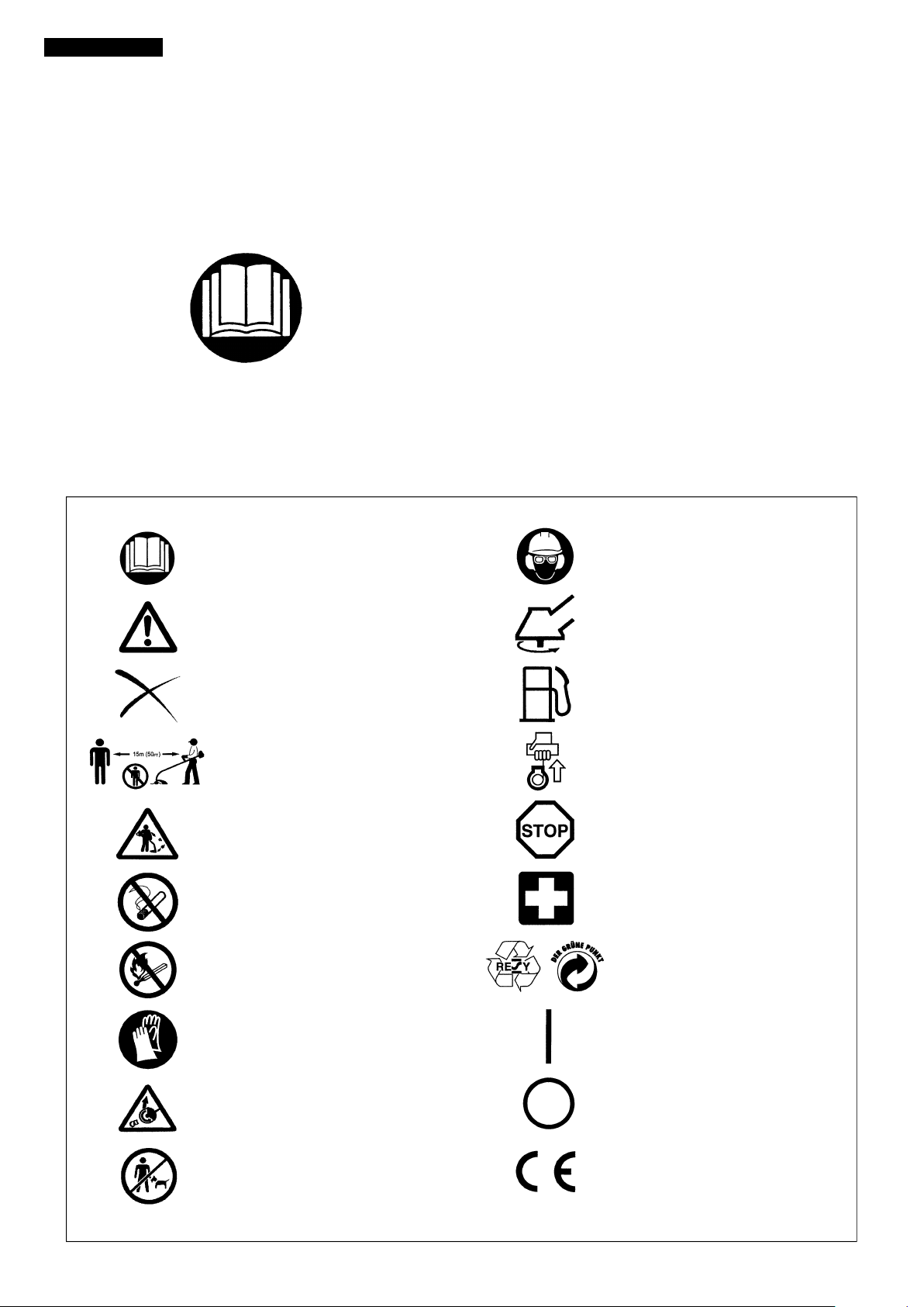
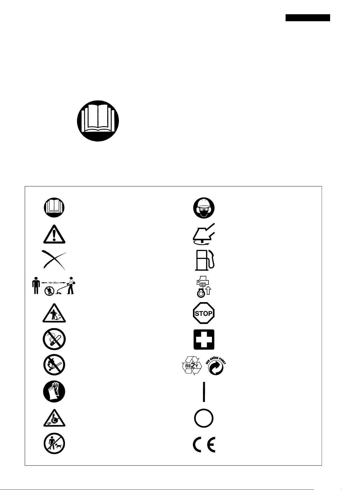
SYMBOLS
It is very important to undestand the following symbols when reading this instructions manual.
Read instruction Manual
WARNING/DANGER/CAUTION
Forbidden
Keep distance
Flying object hazard
No Smoking
No open flame
Wear protective helmet, eye and ear
protection
Top pemissible tool speed
Fuel (Gasoline)
Engine-Manual start
Emergency stop
First Aid
Recycling
Protective gloves must be worn
Kickback (for Brush Cutter only)
Keep the area of operation clear of all
persons and pets
ON/START
OFF/STOP
CE mark
2
Page 3
SAFETY INSTRUCTIONS
General Instructions
– To ensure correct and safe operation, the user must read,
understand and follow this instruction manual to assure
familiarity with the handling of the brush cutter. Users insufficiently informed will risk danger to themselves as well as others
due to improper handling.
– It is recommended only to loan the brush cutter to people who
have proven to be experienced with brush cutters.
Always hand over the instruction manual.
– Use brush cutters with the utmost care and attention.
– First-time users should ask the dealer for basic instructions to
familiarize oneself with the handling of an engine powered
cutter.
– Children and young persons aged under 18 years must not be
allowed to operate the brush cutter. Persons over the age of
16 years may however use the tool for the purpose of being
trained only while under the direct supervision of a qualified
trainer.
– Use brush cutters with the utmost care and attention.
– Operate the brush cutter only if you are in good physical
condition. Perform all work conscientiously and carefully. The
user has to accept responsibility for others.
– Never use the brush cutter while under the influence of alcohol
or drugs.
– Do not use the unit when you are tired.
– Save these instructions for future referral.
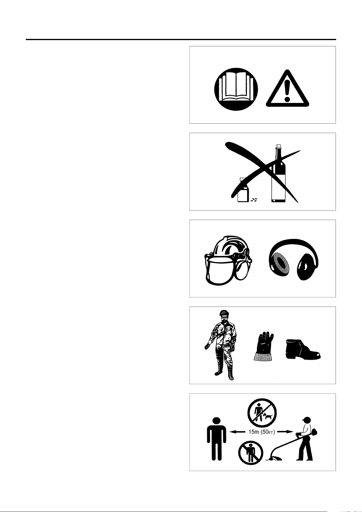
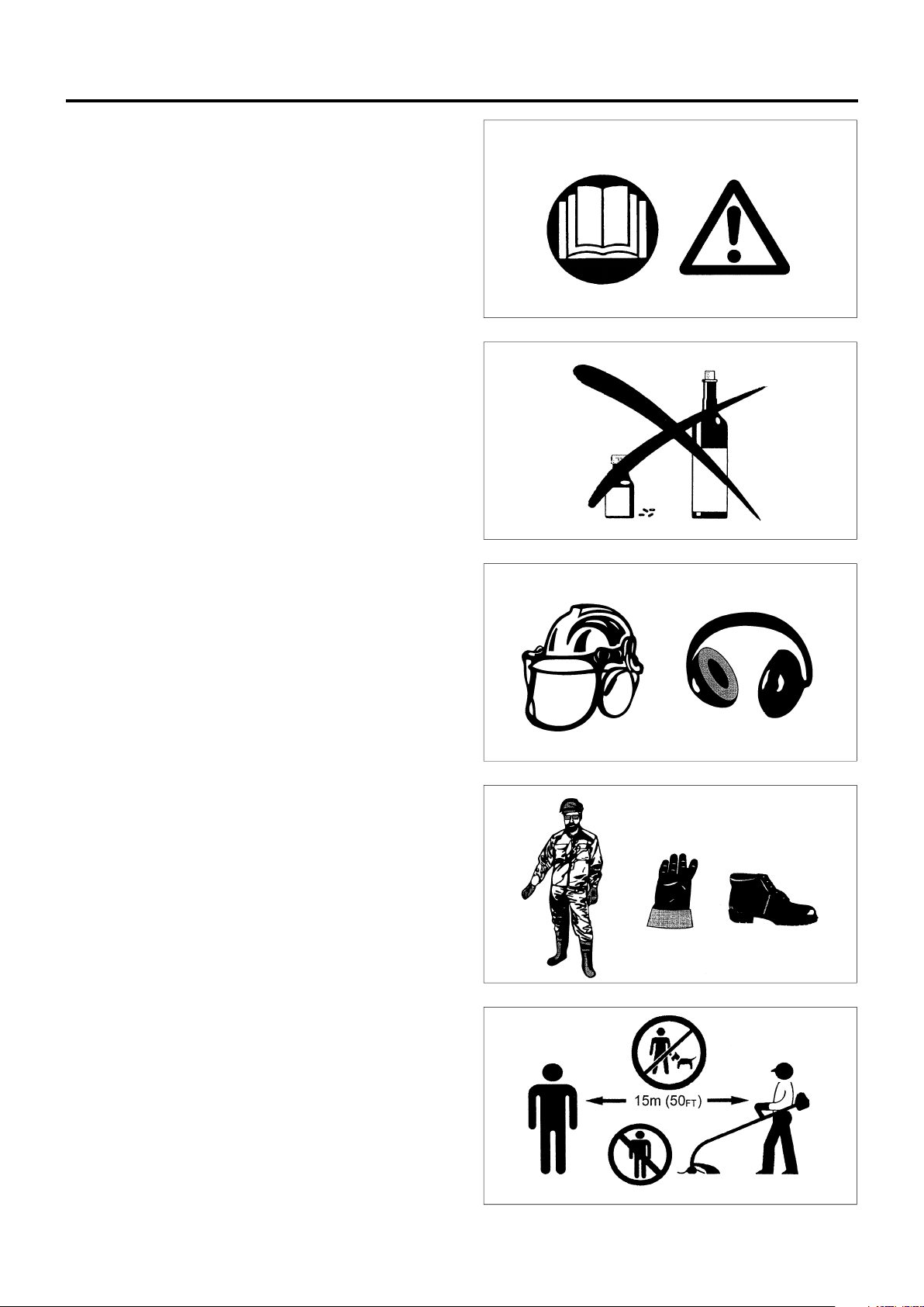
Personal protective equipment
– The clothing worn should be functional and appropriate, i.e. it
should be tight-fitting but not cause hindrance. Do not wear
jewelry, clothing or long hair which could become entangled
with bushes or shrubs.
– In order to avoid head-, eye-, hand- or foot injuries as well as to
protect your hearing the following protective equipment and
protective clothing must be used during operation of the brush
cutter.
– Always wear a helmet when working in the forest. The
protective helmet (1) is to be checed at regular intervals for
damage and is to be replaced at least every 5 years. Use only
approved protective helmets.
– The visor (2) of the helmet (or approved goggles) protects the
face from flying sticks, stones or other object. During operation
of the brush cutter always wear goggles, or a visor to prevent
eye injuries.
– Wear adequate noise protection equipment to avoid hearing
impairment (ear muffs (3), ear plugs etc.), especially during
extended work periods.
– The work overalls (4) protect against flying stones and
splinters.
We strongly recommend that the user wear work overalls.
– Special gloves (5) made of thick leather are part of the pre-
scribed equipment and must always be worn during operation
of the brush cutter.
– When using the brush cutter, always wear sturdy shoes (6)
with a non-slip sole. This protects against injuries and ensures
good footing.
Starting up the brush cutter
– Please make sure that there are no children or other people
within a working range of 50 ft. or 15 meters, also pay attention
to any animals in the working vicinity.
– Before operating, always check that the brush cutter is
safe for operation:
Check the security of the cutter blade. Be sure the blade
mounting nut is firmly secured. The throttle lever should be
checked for smooth and easy action. Check for proper
functioning of the throttle lever lock. The cutter blade must not
rotate during idling.
Consult idle adjustment instructions on page 16. Check for
clean and dry handles and test the function of the STOP switch.
Keep handles free of oil and fuel.
– Before operation, check and follow local; regulations concern-
ing sound level and hours of operations.
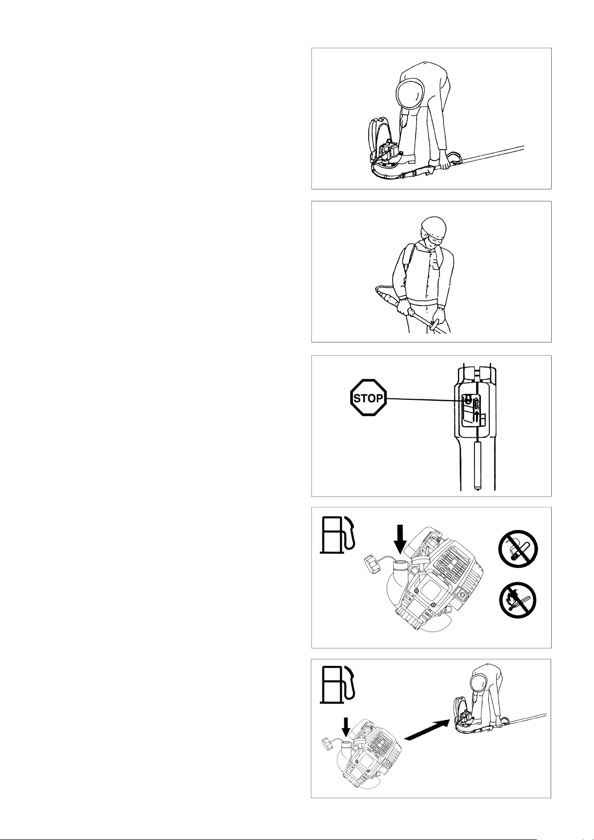
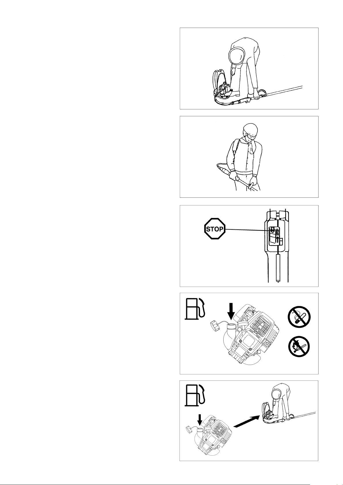
– Only start the brush cutter positioned on the ground.
– Do not start it on the back.
1
2
3
4
5
6
3
Page 4
Start the brush cutter only in accordance with the instructions.
Do not use any other methods for starting the engine!
– Use the brush cutter and the tools supplied only for applications
specified.
– Start the brush cutter engine only after the entire tool has been
assembled. Operation of the tool is permitted only after all the
appropriate accessories are attached!
– Before starting, make sure that the cutter blade will not contact
any objects such as branches, stones, etc.
– The engine is to be stopped immediately if there are any engine
problems.
– Should the cutter blade hit stones or any other objects immedi-
ately stop the engine and inspect the cutter blade.
– Inspect the cutter blade at frequent regular intervals for damage
(detect hairline cracks by means of a tapping-noise test).
– A familiar ringing sound should be heard.
– Operate the brush cutter only with the shoulder strap attached.
It should be properly adjusted before putting the brush cutter
into operation. It is essential to adjust the shoulder strap to the
user’s size to prevent fatigue occurring during use or loss of
control of the tool. Never hold the tool with one hand during
use.
– During operation always hold the brush cutter with both hands.
Always ensure a safe, well-balanced footing.
– Operate the brush cutter in such a manner as to avoid inhalation
of the exhaust gases. Never run the engine in enclosed rooms
(risk of suffocation and gas poisoning). Carbon monoxide is an
odorless gas. Always ensure there is adequate ventilation.
– Stop the engine when resting and when leaving the brush
cutter unattended. Place it in a sale location to prevent danger
to others, setting fire to combustible materials, or damage to the
machine.
– Never lay down the hot brush cutter onto dry grass or onto any
combustible materials.
– The cutter blade must be used with its appropriate guard.
Never run the tool without this guard!
– All protective parts and guards supplied with the machine must
be used during operation.
– Never operate the engine with a faulty exhaust muffler.
– Stop the engine during transport.
– During transport over long distances the tool protection included
with the equipment must always be used.
– Put the brush cutter in upright position and fix it during care or
truck transportation to avoid damage.
– When transporting the brush cutter, ensure that the fuel tank is
completely empty, to avoid fuel leakage.
• Resting
• Transport
• Refuelling
• Maintenance
• Tool Repiacement
Refuelling
– To reduce the risk of fire and bum injury, handle fuel with care it
is highly flammable, Stop the engine during refuelling, keep well
away from open flame and do not smoke.
– Avoid skin contact with petroleum products. Do not inhale fuel
vapor. Always wear protective gloves during refuelling.
Change and clean protective clothing at regular intervals.
– Take care not to spill either fuel or oil. Always wipe unit dry
before starting engine. Allow wet cloths to dry before disposing in proper, covered container to prevent spontaneous
combustion.
– Avoid any fuel contact with your clothing. Change your clothing
immediately if fuel has spilled on it (danger hazard).
– Inspect the fuel cap at regular intervals making sure that stays
securely fastened.
– Carefully tighten the locking screw of the fuel tank. Change
locations to start the engine (at least 10ft. or 3 meters away
from the place of refueling).
– Never refuel in closed rooms. Fuel vapors accumulate at
ground level (risk of explosions).
– Only transport and store fuel in approved containers. Make
sure stored fuel is not accessible to children.
– Do not attempt to refuel a hot or a running engine.
– When mixing gasoline with two-stroke engine oil, use only
gasoline which contains no ethanol or methanol (types of
alcohol). This will help to prevent damage to fuel lines and other
engine parts.
3m (10FT)
4
Page 5

Method of operation
– Use the brush cutter only in good light and visibility. During cold
seasons beware of slippery or wet areas, ice and snow (risk
of slipping). Always ensure a safe footing.
– Do not overreach. Keep proper footing, balance and hand
control of the unit at all times.
– Never cut above waist level.
– Never stand on a ladder while running the brush cutter.
– never climb up into trees to perform any cutting operation with
the brush cutter.
– Never work on unstable surfaces or steep terrain.
– Remove all objects such as stones, nails, broken glass, wire,
etc. found within the working ares.
Foreign articles may damage the cutting tool, can cause
dangerous kickbacks, or could be thrown about dangerously.
– Before commencing cutting the cutting tool must have reached
full working speed.
– Never operate this tool while it is turned upside-down or when
it is at an extreme angle.
– !WARNING! — The cutter area is still dangerous while the
machine is coasting to a stop.
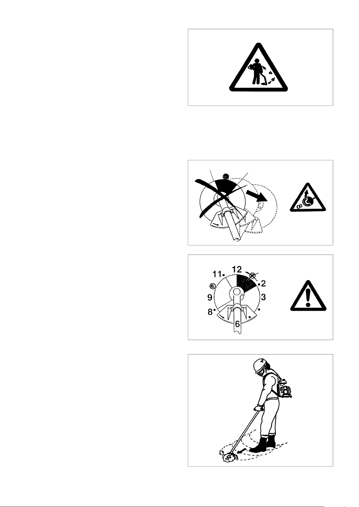
Kickback
– When operating the brush cutter, uncontrolled kickback can
occur.
– This particularly is the case when attempting to cut within a
blade segment between 12 and 2 o’clock as viewed from the
operator’s position.
– Never touch this segment of the brush cutter to solid objects,
such as bushes, stumps, trees, etc., with a diameter greater
than 3 cm.
– The brush cutter will then be deflected at great force and speed
with the potential risk of serious injuries.
– Never operate the brush cutter using the blade seg-
ment between the 12 and 2 o’clock position.
Kickback prevention
To avoid kickbacks, observe the following:
– Operation within the blade segment between 12 and 2 o’clock
can cause serious potential hazards, especially when using
metal cutting blades.
Use of this brush cutter utilizing blade segment positions from
11 to 12 o’clock and 2 to 5 o’clock can still cause a likely
potential for some kickback.
– Cutting operations attempted within the blade segments
between 11 and 12 o’clock, and between 2 and 5 o’clock,
should only be performed by trained and experienced opera-
tors, and only at their own risk. Smooth and easy cutting with
almost no kickback is possible using the blade segment be-
tween 8 and 11 o’clock.
12
2
Caution: Kickback
Diagrammatic figure
Diagrammatic figure
Cutting Tools
Use only the correct cutting tool for the specific job in hand.
Cutter blade (Star Blade (4 teeth), Eddy Blade (8 teeth)):
For cutting thick materials, such as weeds, high grass, bushes,
shrubs, underwood, thicket, etc. (max. 2 cm dia. thickness).
Perform this cutting work by swinging the brush cutter evenly in
half-circles from right to left (similar to using a scythe).
Maintenance instructions
– The condition of the cutter, in particular of the cutter blade,
guard and of the shoulder strap must be checked before
commencing work. Particular attention is to be paid to the
cutting blades which must be correctly sharpened.
– Turn off the engine and remove spark plug connectors when
replacing or sharpening cutting blade, and also when cleaning
the cutter or cutting tool.
5
Page 6
Never straighten or weld damaged cutting blades.
– Be kind to the environment. Operate the brush cutter with as
little noise and pollution as possible. In particular check the
correct adjustment of the carburetor.
– Clean the brush cutter at regular intervals and check that all
screws and nuts are securely tightened.
– Never service or store the brush cutter in the vicinity of open
flames, sparks, etc.
– Always store the brush cutter in a well-ventilated locked room
and with an emptied fuel tank.
Observe and follow all relevant accident prevention instructions
issued by the trade associations and by insurance companies.
Do not perform any modifications to the brush cutter as this will
risk your safety.
The performance of maintenance or repair work by the user is
limited to those activities s described in this instruction manual. All
other work is to be done by Authorized Service Agents.
Use only genuine spare parts and accessories supplied by
MAKITA.
Use of non-approved accessories and tools means increased risk
of accidents and injuries. MAKITA will not accept any liability for
accidents or damage caused by the use of any non-approved
cutting tools attachments or accessories.
First Aid
In case of accident make sure that a well-stocked first-aid kit is
available in the vicinity of the cutting operations. Immediately
replace any item taken from the first aid box.
When asking for help, please give the following information:
– Place of accident
– What happened
– Number of injured persons
– Extent of injuries
– Yo u r n a me
Packaging
The MAKITA brush cutter is delivered in two protective cardboard
boxes to prevent shipping damage.
Cardboard is a basic raw material and is therefore consequently
reusable or suitable for recycling (waste paper recycling).
6
Page 7

EC-DECLARATION OF CONFORMITY
Model; EBH341R
We declare under our sole responsibility that this product is in compliance with the following standards of
standardized documents, ISO14865, ISO14740, EN55012 in accordance with Council Directives, 89/392/
EEC, amended 98/37/EEC, 93/68/EEC, 89/336/EEC, amended 92/31/EEC.
Measured Sound Power: 108.4 dB
Guarantee Sound Power: 113.3 dB
These sound power levels wear measured in accordance with Council Directive, 2000/14/EC.
Conformity assessment procedure: Annex V.
CE2007
Tomoyasu Kato
Director
Responsible Manufacturer:
Makita Corporation.
3-11-8,Sumiyoshi-cho, Anjo, Aichi, JAPAN
Authorized Representative in Europe:
Makita International Europe Ltd.
Michigan Drive, Tongwell, Milton kyenes, Bucks MK15 8JD, ENGLAND
7
Page 8

TECHNICAL DATA
Model
Dimensions : length x width x height (without pipe case length) mm
Mass (without guard and cutting blade) kg
Volume (fuel tank) L
Cutting attachments (cutter blade dia.) mm
Engine displacement cm
Maximum engine performance kw
Engine speed at recommended max. spindle speed min
Maximum spindle speed (corresponding) min
Fuel consumption kg/h
Specific fuel consumption g/kwh
EBH341R
Loop handle
Cutter blade Nylon cutting head
430 x 280 x 430
10.2
0.65
255
3
-1
-1
33.5
1.07 at 7000 min
10000
7500
-1
0.458
426
Idling speed min
Clutch engagement speed min
Carburetor (Diaphragm - carburetor) type
Ignition system type
Spark plug type
Electrode gap mm
Right handle
1)
(Rear grip)
Vibration per
ISO 7916
Left handle
(Frontgrip)
Sound pressure level average to ISO 7917
Sound power level average to ISO 10884
Idling m/s
Racing or W.O.T m/s
Idling m/s
Racing or W.O.T m/s
1)
1)
dB
dB
Fuel
Engine oil
-1
-1
3000
4100
WALBRO WYL
Solid state ignition
NGK CMR6A
0.7 – 0.8
2
2
2
2
0.6 0.7
4.0 5.59
0.85 0.82
4.78 8.12
89.3 97.1
104.3 108.4
Automobile gasoline
SAE 10W-30 oil API Classification,
Class SF or higher (4-stroke engine for automobile).
Gear ratio
1) This data takes equally into account idling and full speed or wide open throttle operating modes.
8
15/20
Page 9

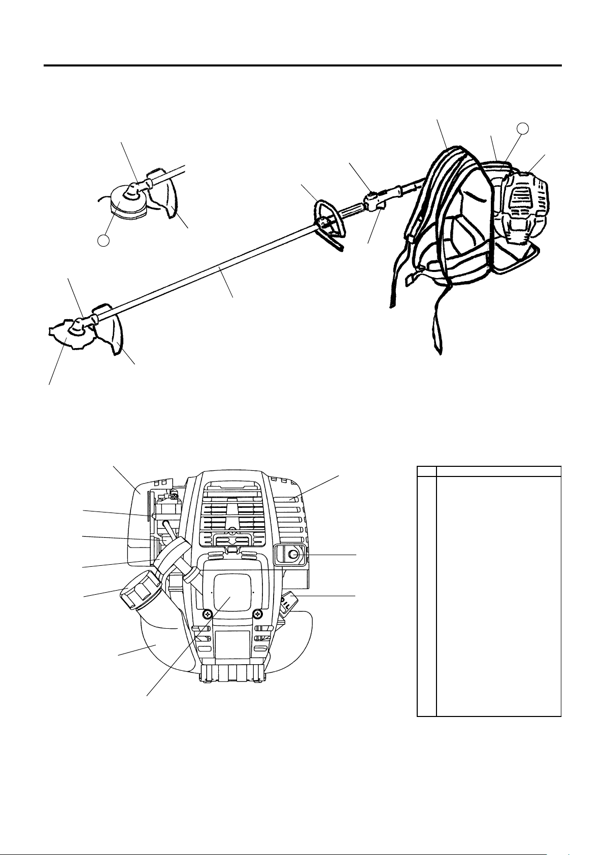
DESIGNATION OF PARTS
ԣ
ԥ
Ԡ
Ԥ
ԣ
ԛ
Ԝ
Ԟ
Ԣ
ԟ
ԡ
Ԣ
ԩ
Ԩ
ԧ
Ԧ
Ԛ
Ԙ
ԙ
ԝ
Ԫ
ԫ
GB DESIGNATION OF PARTS
1 Fuel Tank
2 Rewind Starter
3 Air Cleaner
4 I-O Switch (on/off)
5 Spark Plug
6 Exhaust Muffler
7 Handle
8 Control Lever
9 Control Cable
10 Shaft
11 Protector
12 Gear Case/Head Case
13 Cutter Blade
14 Shoulder Strap
15 Fuel Filler Cap
16 Starter Knob
17 Primmer Pump
18 Choke Lever
19 Exhaust Pipe
20 Oil Gauge
21 Flexible Pipe
22 Nylon Cutting Head
9
Page 10
ASSEMBLY OF ENGINE AND DRIVE SHAFT
CAUTION : Before performing any work on the brush
CAUTION : Start the brush cutter only after having as-
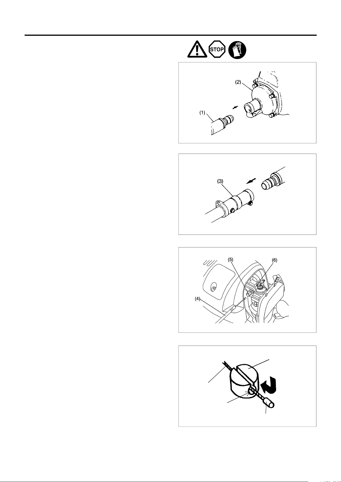
1. Joining flexible pipe with engine and pipe case holder
Insert on end of a flexible pipe (1) into a clutch housing (2) on
an engine until it locks with a slight “click” noise.
Insert the other end of the flexible pipe into a pipe case (3)
holder of a brush cutter until it locks.
Each end of the flexible pipe is interchangeable.
Make sure that a squsre end of a flexible shaft fits into the joint
of a drive shaft.
CAUTION : If you have difficulty to insert the flexible pipe
cutter, always switch off the motor and pull the
spark plug connectors off the spark plug.
Beware of hot engine pars and sharp blade
edges.
Always wear protective gloves!
sembled it completely.
properly, the square end of the flexible shaft
may not fit the drive shaft joint. Do not force to
push to avoid damage on the flexible shaft end.
Repeat the same procedure again until flexible
shaft and pipe fit properly.
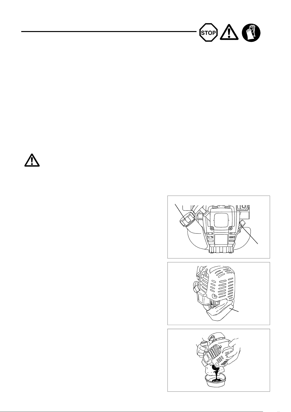
2. Mounting of control cable
– Remove the air cleaner cover.
– Place the control cable (4) in the adjusting bolt (5), and shift the
swivel (6) so that the cable will be put in the swivel groove. At
this time, the round-hole side of the swivel will be oriented
toward the inner wire end-metal fitting.
– Release the swivel, and confirm that the inner wire-end metal
fitting will be placed in the hole.
– Mount the air cleaner cover.
Swivel
Control cable
Insert
Round-hole
End fitting
10
Page 11
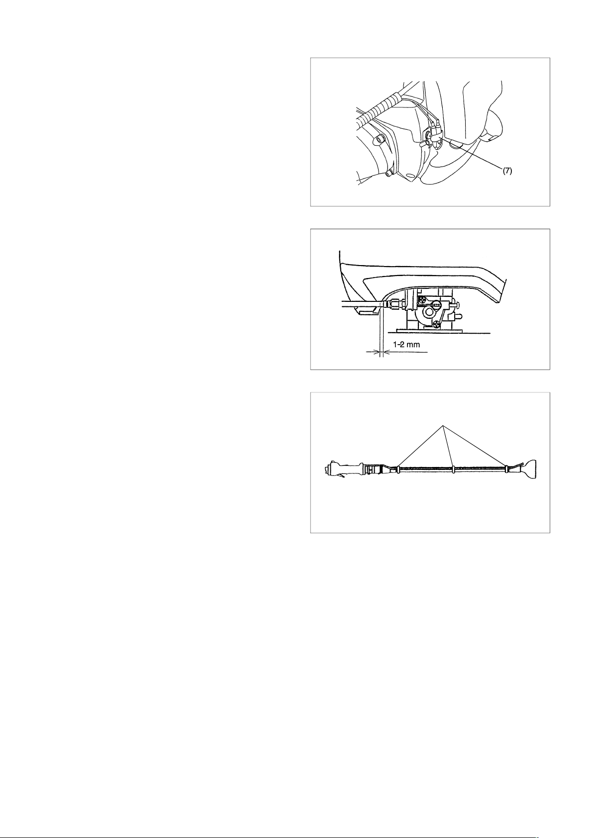
CONNECTION OF SWITCH CORD
– Connect the switch cords to the two cords from the engine by
inserting one into the other.
– Fix the cord connector by clamp (7).
ADJUSTMENT OF CONTROL CABLE
– Adjust the control cable by adjusting bolt so that it will have 1 to
2 mm play when the throttle lever is set to the low-speed
position by carburetor adjusting bolt. (Be careful that the cutter
blade will not turn in idling.)
Make the throttle wire and I-O switch cords go along the flexible
pipe and fix three point them on clip wire (8) tightly. If you do not
fix the throttle wire and I-O switch cords surely, there is fear that
they catch on the branch and so on it is dangerous.
11
Page 12
MOUNTING OF HANDLE
– Fix a barrier to the left side of the machine together with the
handle for operator’s protection.
– Do not adjust position of the loop handle too close to the control
grip. Keep not less than 25cm distance between the handle
and the grip.
(a distance collar is provided for this purpose.)
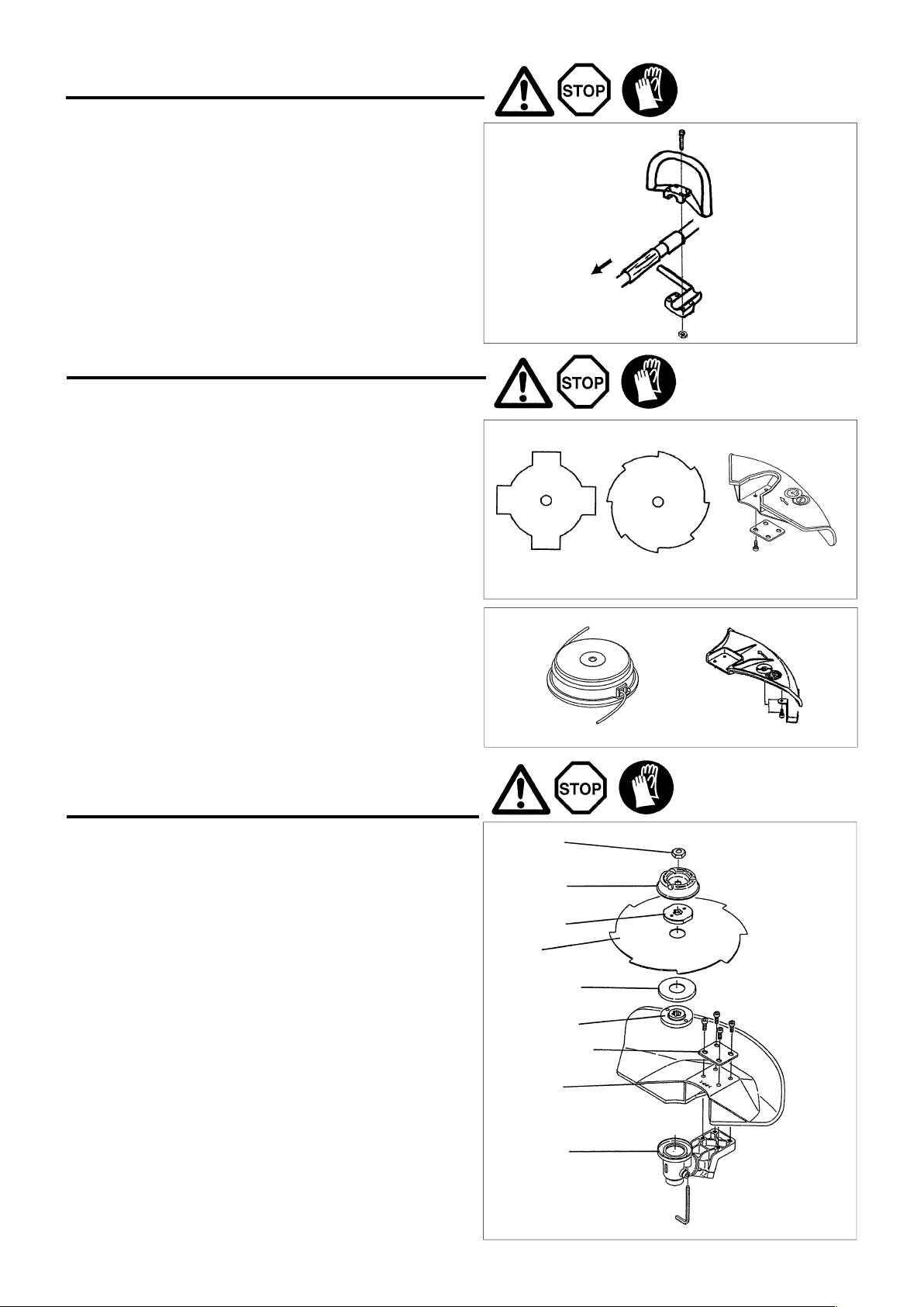
MOUNTING OF PROTECTOR
To meet the applicable safety provisions, only the tool/protector
combinations as indicated in the table must be used. Failure to do
so may result in serious injury or death to user or bystanders.
Be sure to use genuine MAKITA cutter blade or nylon
cutting head.
– The cutter blade must be well clean, sharp and free of cracks
or breakage.
If the cutter blade contacts any hard objects or stones during
operation, stop the engine and check the blade immediately.
– Clean and sharpen or replace the cutter blade at least every
three hours of operation.
– The outside diameter of the cutter blade must not exceed 255
mm (10-1/32”). Never use any blades surpassing 255 mm (10-
1/32”) in outside diameter.
CAUTION : The appropriate guard must always be in-
stalled, for your own safety and in order to
comply with accident-prevention regulations.
Operation of the equipment without the
protector being properly in place must never
be attempted.
– Fix protector to a gear case by 4 bolts firmly
Never use a blush cutter without a protector or with a broken
protector.
to engine
Star Blade
PART NO.
6418501400
Nylon cutting head
PART NO.6348003000 PART NO.174345800
Eddy Blade
PART NO.
6418501900
Protector for metal
blades
PART NO.
6118502000
MOUNTING OF CUTTER BLADE OR
NYLON CUTTING HEAD
Turn the machine upside down, and you can replace the cutter
blade or nylon cutting head easily.
Mounting of cutter blade
– Fit a cutting blade and other parts in the order as in the illustra-
tion. Thrust a bar or allen wrench into a hole of the gear case
until the cutting blade is locked and will not turn. Tighten a nut
by turning to counter-clockwise with a combination wrench.
(Note that the nut is tightened or loosened in the opposit
direction of a usual nut.)
– The nut must be re-tightened every time before use.
– For this brush cutter, we recommend the cutting attachments on
the right.
– Never attempt to cut a tree, a log, wood or other hard materials.
[Tightening torque: 28 – 48 N
NOTE : Always wear gloves when handling the cutter
blade.
Mounting of nylon cutting head
– The blade cap, bolt cover and nut are not necessary for
mounting the nylon cutting head. The nylon cutting head should
go on top of the grass cover.
– Insert the allen wrench through the hole in the gear case and
rotate the blade holder until it is locked with the alln wrench.
– Then screw the nylon cutting head onto the shaft by turning it
counter-clockwise.
– Remove the allen wrench.
m]
Nut
Bolt cover
Blade cap
Blade
Grass cover
Blade holder
Protector plate
Protector
Gear case
12
Page 13
BEFORE START OF OPERATION
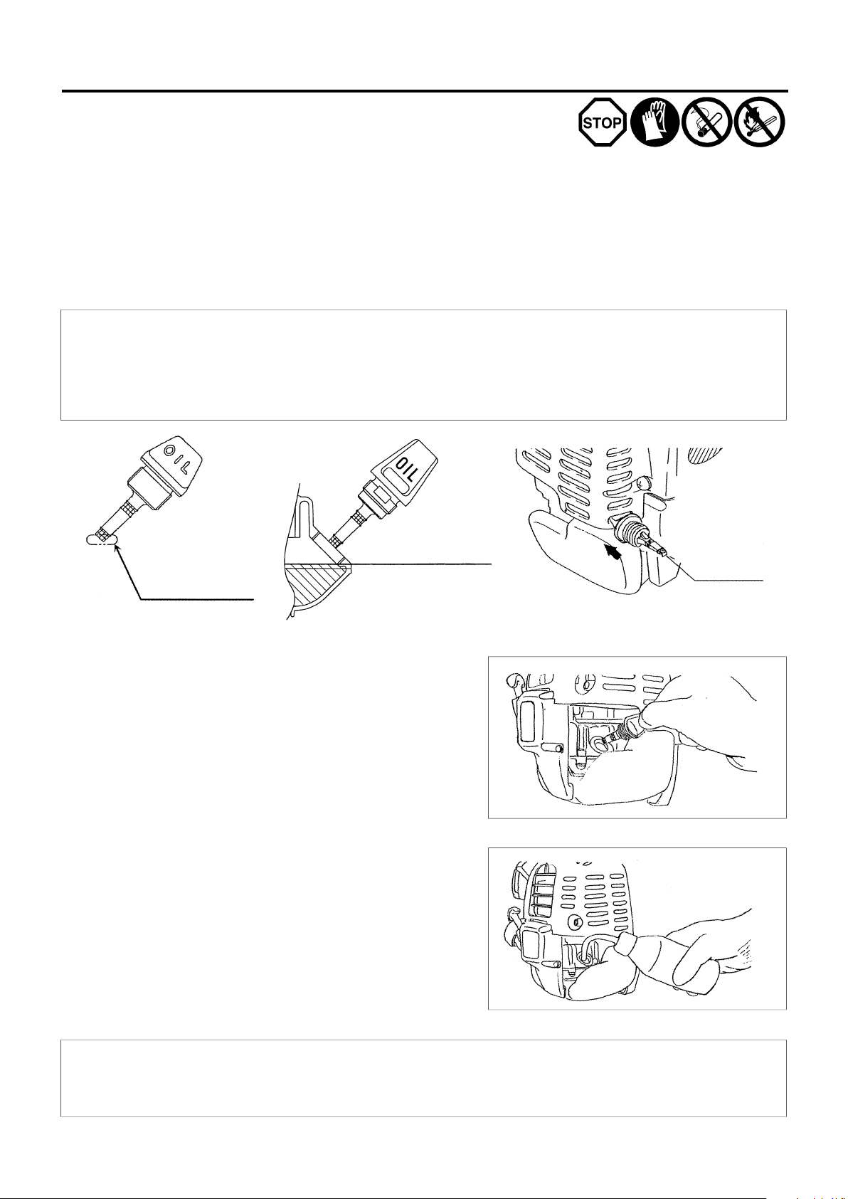
Inspection and Refill of Engine Oil
– Perform the following procedure, with the engine cooled down.
– While keeping the engine level, remove the oil gauge, and confirm that the oil is filled within the upper and lower limit marks.
When the oil is in short in such a way that the oil gauge touches the oil only by its tip, in particular with the oil gauge remaining inserted in the
crankcase without screwing-in (Fig. 1), refill new oil near the port (Fig. 2).
– For reference, the oil refill time is about 15 h (refill frequency: 15 times).
– If the oil changes in color or mixes with dirt, replace it with new one. (For the interval and method of replacement, refer to P. 1 7)
Recommended oil: SAE 10W-30 oil of API Classification, Class SF or higher (4-stroke engine for automobile)
Oil volume: Approx. 0.1 L
Note: If the engine is not kept upright, oil may go into around the engine, and may be refilled excessively.
If the oil is filled above the limit, the oil may be contaminated or may catch fire with white.
Point 1 in Replacement of Oil "Oil Gauge"
– Remove dust or dirt near the oil refill port, and detach the oil gauge.
– Keep the detached oil gauge free of sand or dust. Otherwise, any sand or dust adhering to the oil gauge may cause irregular oil
circulation or wear on the engine parts, which will result in troubles.
– As an example to keep the oil gauge clean, it is recommended to insert the oil gauge on its knob side into the engine cover, as shown in
Fig.3.
Upper limit of oil level
(Lower part of oil refill port
threaded part)
If oil adheres around
this tip refill new oil.
Fig.1
(1) Keep the engine level, and detach the oil gauge.
(2) Fill oil up to the edge of the oil refill port. (Refer to Fig.2 of the preceding
page).
Feed oil with the lubricant refill container.
Fig.2
Oil gauge
Fig.3
(3) Securely tighten the oil gauge. Insufficient tightening may cause oil leakage.
Point 2 in Replacement of Oil: “If oil spills out”
– If oil spills out between the fuel tank and engine main unit, the oil is sucked into through the cooling air intake port, which will contaminate
the engine. Be sure to wipe out spilt oil before start of operation.
13
Page 14
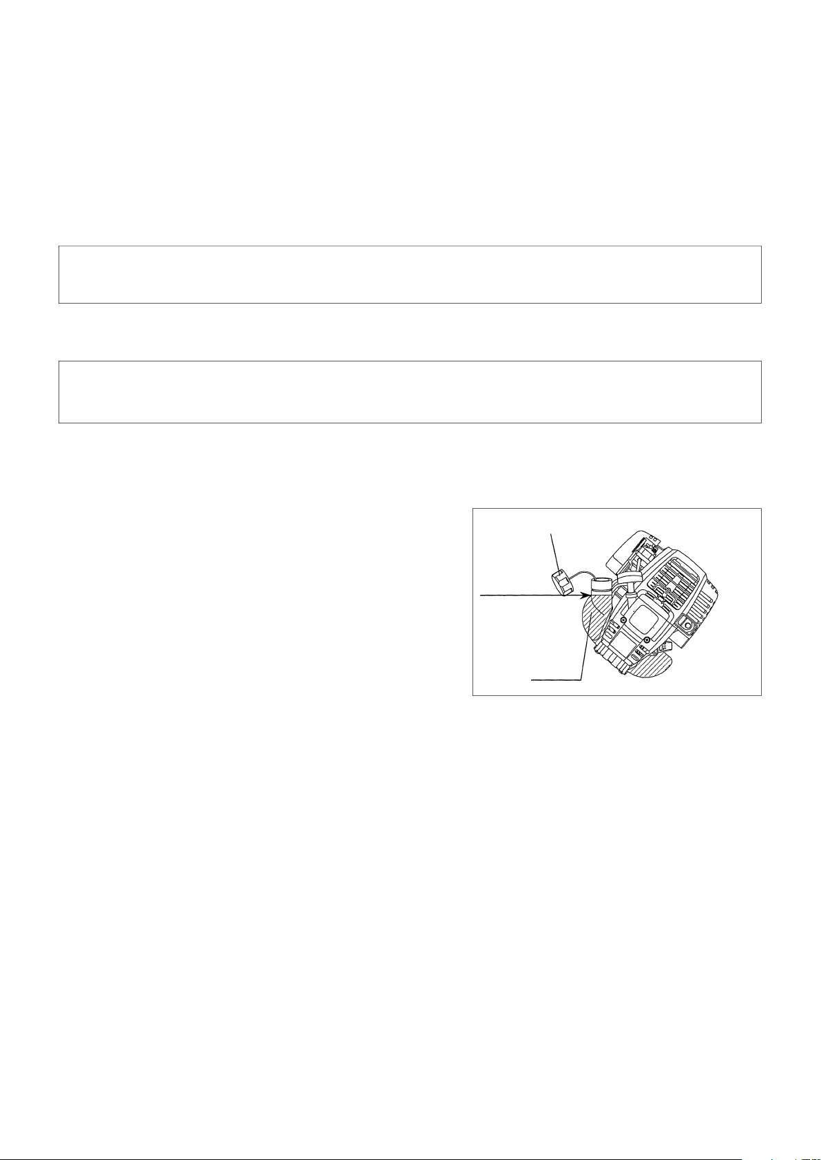
REFUELING
Handling of Fuel
It is necessary to handle fuel with utmost care. Fuel may contain substances similar to solvents. Refueling must be performed in a sufficiently
ventilated room or in the open air. Never inhale fuel vapor, and keep fuel away from you. If you touch fuel repeatedly or for a long time, the skin
becomes dry, which may cause skin disease or allergy. If fuel enters into the eye, clean the eye with fresh water. If your eye remains still irritated,
consult your doctor.
Storage Period of Fuel
Fuel should be used up within a period of 4 weeks, even if it is kept in a special container in a well-ventilated shade.
If a special container is not used or if the container is not covered, fuel may deteriorate in one day.
STORAGE OF MACHINE AND REFILL TANK
– Keep the machine and tank at a cool place free from direct sunshine.
– Never keep the fuel in the cabin or trunk.
Fuel
The engine is a four-stroke engine. Be sure to use an automobile gasoline (regular gasoline or premium gasoline).
Points for Fuel
– Never use a gasoline mixture which contains engine oil. Otherwise, it will cause excessive carbon accumulation or mechanical troubles.
– Use of deteriorated oil will cause irregular startup.
Refueling
WARNING: INFLAMMABLES STRICTLY PROHIBITED
Gasoline Usedl: Automobile gasoline (unleaded gasoline)
– Loosen the tank cap a little so that there will be no difference in atmospheric
pressure.
– Detach the tank cap, and refuel, discharging air by tilting the fuel tank so that
the refuel port will be oriented upward. (Never refill fuel full to the oil refill
port.)
– Wipe well the periphery of the tank cap to prevent foreign matter from
entering into the fuel tank.
– After refueling, securely tighten the tank cap.
• If there is any flaw or damage on the tank cap, replace it.
• The tank cap is consumable, and therefore should be renewed every two to
three years.
Fuel tank cap
Fuel upper limit
Fuel tank
14
Page 15
POINTS IN OPERATION AND HOW TO STOP
Observe all applicable accident prevention regulations!
STARTING
Move at least 3m away from the place of refuelling. Place the brush cutter on a clean piece of ground taking care that the cutting tool does
not come into contact with the ground or any other objects.
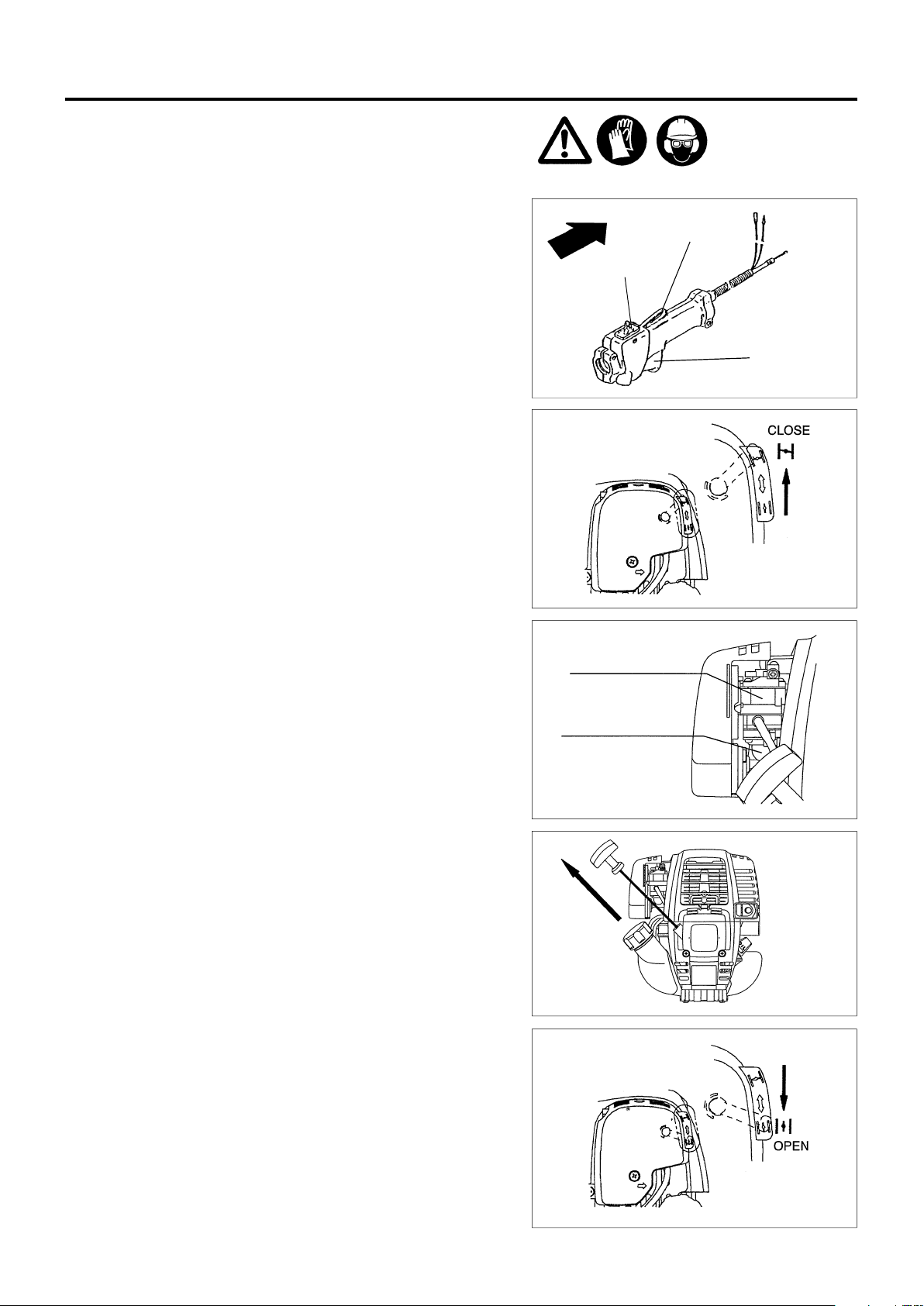
OPERATION
Lock-off lever
A:Cold start
1) Set this machine on a flat space.
2) Set the I-O switch (1) to OPERATION.
3) Choke lever
Close the choke lever.
Choke opening:
– Full closing in cold or when the engine is cold.
– Full or half opening in restart just after stop of operation.
I-O switch (1)
Throttle lever(6)
4) Primer pump
Continue to push the primer pump until fuel enters into the primer pump. (In
general, fuel enters into the primer pump by 7 to 10 pushes.)
If the primer pump is pushed excessively, an excess of gasoline returns to
the fuel tank.
5) Recoil starter
– Pull the start knob gently until it is hard to pull (compression point). Then,
return the start knob, and pull it strongly.
– Never pull the rope to the full. Once the start knob is pulled, never
release your hand immediately. Hold the start knob until it returns to its
original point.
6) Choke lever
When the engine starts, open the choke lever.
– Open the choke lever progressively while checking the engine operation.
Be sure to open the choke lever to the full in the end.
– In cold or when the engine is cooled down, never open the choke lever
suddenly. Otherwise, the engine may stop.
Caburettor
Primer Pump
7) Warm-up operation
Continue warm-up operation for 2 to 3 minutes.
15
Page 16
Note: – If the starter handle is pulled repeatedly when the choke lever remains at "CLOSE" position, the engine will not start easily due to
excessive fuel intake.
– In case of excessive fuel intake, remove the spark plug and pull the starter handle slowly to remove excess fuel. Also, dry the
electrode section of the spark plug.
Caution during operation:
If the throttle lever is opened fully in a no-load operation, the engine rotation is increased to 10,000rpm or more. Never operate the engine at
a higher speed than required and at an approximate speed of 6,000 - 8,500rpm.
B: Startup after warm-up operation
1) Push the primer pump repeatedly.
2) Keep the throttle lever at the idling position.
3) Pull the recoil starter strongly.
4) If it is difficult to start the engine, open the throttle by about 1/3.
Pay attention to the cutter blade which may rotate.
Attention in Operation
When the engine is operated upside down, white smoke may come out from the muffler.
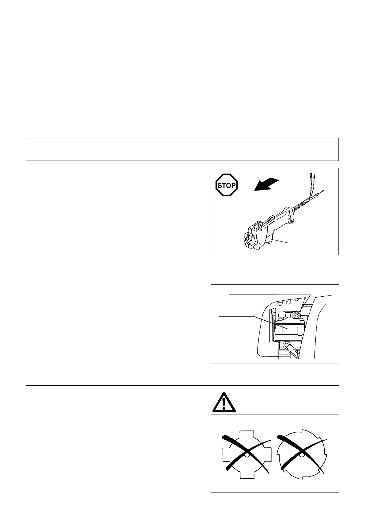
STOPPING
1) Release the throttle lever (6) fully, and when the engine rpm has lowered,
set the I-O switch to STOP the engine will now stop.
2) Be aware that the cutting head may not stop immediately and allow it to
slow down fully.
STOP
I-O switch (1)
ADJUSTMENT OF LOW-SPEED ROTATION (IDLING)
When it is necessary to adjust the low-speed rotation (idling), perform it by the carburetor adjusting screw.
CHECKUP OF LOW-SPEED ROTATION
– Set the low-speed rotation to 3000min-1.
If it is necessary to change the rotation speed, regulate the adjusting screw
(illustrated on the left), with Phillips screwdriver.
– Turn the adjusting screw to the right, and the engine rotation will increase.
Turn the adjusting screw to the left, and the engine rotation will drop.
– The carburetor is generally adjusted before shipment. If it is necessary to
readjust it, please contact Authorized Service Agent.
Adjusting screw
Carburetor
RESHARPNING THE CUTTER BLADE
CAUTION : The cutter blade mentioned below must only be
resharpened by an authorized facility. Manual
resharpening will result in imbalances of the cutting
tool causing potentially dangerous vibrations and
damage to the equipment.
Throttle lever (6)
– Cutter blade (Star blade (4 teeth), Eddy blade (8 teeth))
An expert resharpening and balancing service is provided by
Authorized Service Agents.
NOTE : To increase the service life of the cutter blade (star blade,
eddy blade) it may be turned over once, until both cutting
edges have become dull. Never continue to use a dull
blade or kickback and serious injury may result.
16
Page 17
SERVICING INSTRUCTIONS
CAUTION : Before doing any work on the brush cutter, always stop the engine and pull the plug cap off the spark plug (see "checking the spark plug").
To ensure a long service life and to avoid any damage to the equipment, the following servicing operations should be performed at regular intervals.
Always wear protective gloves!
Daily checkup and maintenance
– Before operation, check the machine for loose screws or missing parts. Pay particular attention to the tightness of the cutter blade or
nylon cutting head.
– Before operation, always check for clogging of the cooling air passage and the cylinder fins.
Clean them if necessary.
– Perform the following work daily after use:
• Clean the brush cutter externally and inspect for damage.
• Clean the air filter. When working under extremely dusty conditions, clean the filter the severall times a day.
• Check the blade or the nylon cutting head for damage and make sure it is firmly mounted.
• Check that there is sufficient difference between idling and engagement speed to ensure that the cutting tool is at a standstill while the
engine is idling (if necessary reduce idling speed).
If under idling conditions the tool should still continue to run, consult your nearest Authorized Service Agent.
– Check the functioning of the I-O switch, the lock-off lever, the control lever, and the look button.
REPLACEMENT OF ENGINE OIL
Deteriorated engine oil will shorten the life of the sliding and rotating parts to a great extent. Be sure to check the period and quantity of replacement.
ATTENTION: In general, the engine main unit and engine oil still remain hot just after the engine is stopped. In replacement of oil,
Note: If the oil filled above the limit, it may be contaminated or may catch fire with white smoke.
Interval of replacement: Initially, every 20 operating hours, and subsequently every 50 operating hours
Recommended oil: SAE10W-30 oil of API Classification SF Class or higher (4-stroke engine oil for automobile)
In replacement, perform the following procedure.
1) Confirm that the tank cap is tightened securely.
2) Detach the oil gauge.
Keep the oil gauge free from dust or dirt.
confirm that the engine main unit and engine oil are sufficiently cooled down. Otherwise, there may remain a risk of scald.
Fuel tank cap
3) Place waste or paper near the oil refill port.
4) Detach the oil gauge, and drain oil, tilting the main unit toward the oil refill
port
Drain oil in a container.
Oil gauge
Waste or paper
17
Page 18
5) Keep the engine level, and feed new oil up to the edge of the oil refill port.
In refill, use a lubricant refill container.
6) After refill, securely tighten the oil gauge. Insufficient tightening of the oil
gauge will lead to oil leakage.
POINTS ON OIL
– Never discard replaced engine oil in garbage, earth or sewage ditch. Disposal of oil is regulated by law. In disposal, always follow the
relevant laws and regulations. For any points remaining unknown, contact Authorized Service Agent.
– Oil will deteriorate even when it is kept unused. Perform inspection and replacement at regular intervals (replace with new oil every 6
months).
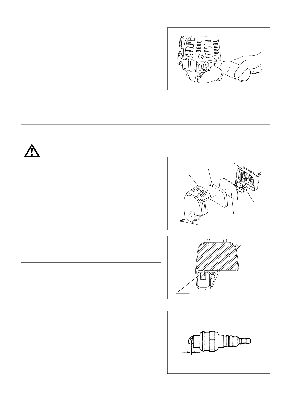
CLEANING OF AIR CLEANER
DANGER: INFLAMMABLES STRICTLY PROHIBITED
Interval of Cleaning and Inspection: Daily (every 10 operating hours)
– Turn the choke lever to the full close side, and keep the carburetor off
from dust or dirt.
– Remove the air cleaner cover-fixing bolts.
– Pull the cover lower side and detach the air cleaner cover.
– If oil adheres to the element (sponge), squeeze it firmly.
– For heavy contamination:
1) Remove the element (sponge), immerse it in warm water or in waterdiluted neutral detergent, and dry it completely.
2) Clean the element (felt) with gasoline, and dry it completely.
– Before attaching the element, be sure to dry it completely. Insufficient
drying of the element may lead to difficult startup.
– Wipe out with waste cloth, oil adhering around the air cleaner cover and
plate breather.
– Immediately after cleaning is finished, attach the cleaner cover and
tighten it with fixing bolts. (In remounting, first place the upper claw, and
then the lower claw.)
Points in Handling Air Cleaner Element
– Clean the element several times a day, if excessive dust adheres to it.
– If operation continues with the element remaining not cleared of oil, oil in
the air cleaner may fall outside, resulting in oil contamination.
Element (sponge)
Air cleaner cover
Fixing bolt
Pick this part and remove the element (felt).
Plate
Breather Part
Element (felt)
CHECKING THE SPARK PLUG
– Only use the supplied universal wrench to remove or to install the spark plug.
– The gap between the two electrodes of the spark plug should be 0.7-0.8mm
(0.028"-0.032"). If the gap is too wide or too narrow, adjust it. If the spark
plug is clogged with carton or fouled, clean it thoroubhly or replace it.
CAUTION : Never touch the spark plug connector while the engine is running
(danger of high voltage electric shock).
18
0.7 mm - 0.8 mm
(0.028”-0.032”)
Page 19
SUPPLY OF GREASE TO GEAR CASE
– Supply grease (Shell Alvania 2 or equivalent) to the gear case through the
grease hole every 30 hours. (Genuine MAKITA grease may be purchased
from your MAKITA dealer.)
Grease hole
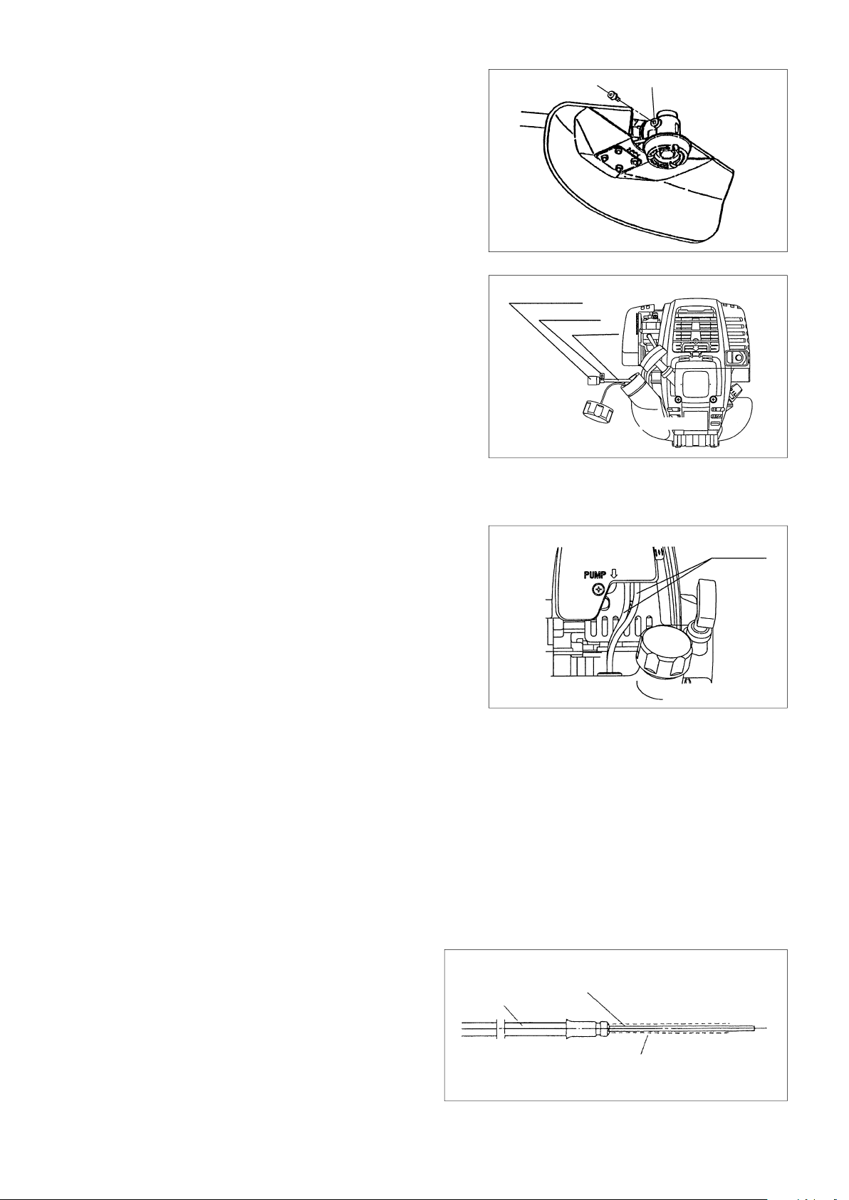
CLEANING OF FUEL FILTER
WARNING: INFLAMMABLES STRICTLY PROHIBITED
Interval of Cleaning and Inspection: Monthly (every 50 operating hours)
Suction head in the fuel tank
– The fuel filler (1) of the suction head is used to filler the fuel required by the
carburetor.
– A periodical visual inspection of the fuel filter is to be conducted. For that
purpose open the tank cap, use a wire hook and pull out the suction head
through the tank opening. Filters found to have hardened, been polluted or
clogged up are to be replaced.
– Insufficient fuel supply can result in the admissible maximum speed being
exceeded. It is therefore important to replace the fuel filter at least quarterly to
ensure satisfactory fuel supply to the carburetor.
REPLACEMENT OF FUEL PIPE
CAUTION: INFLAMMABLES STRICTLY PROHIBITED
Interval of Cleaning and Inspection: Daily (every 10 operating hours)
Replacement: Annually (every 200 operating hours)
Replace the fuel pipe every year, regardless of operating frequency. Fuel leakage
may lead to fire.
If any leakage is detected during inspection, replace the oil pipe immediately.
INSPECTION OF BOLTS, NUTS AND SCREWS
– Retighten loose bolts, nuts, etc.
– Check for fuel and oil leakage.
– Replace damaged parts with new ones for safety operation.
Fuel filter (1)
Hose clamp
Fuel pipe
Fuel pipe
CLEANING OF PARTS
– Keep the engine always clean.
– Keep the cylinder fins free of dust or dirt. Dust or dirt adhering to the fins will cause seizure.
REPLACEMENT OF GASKETS AND PACKINGS
In reassembling after the engine is dismounted, be sure to replace the gaskets and packings with new ones.
SUPPLY OF GREASE TO THE FLEXIBLE SHAFT
- Pull out the flexible shaft from the flexible lining for every 20 hours,
and apply grease on the flexible shaft.
- The flxible shaft may be broken if no grease is applied.
Flexible liner
Any maintenance of adjustment work that is not been included and described in this manual is only to be performed by Authorized Service
Agents.
Flexible shaft
Apply grease
19
Page 20
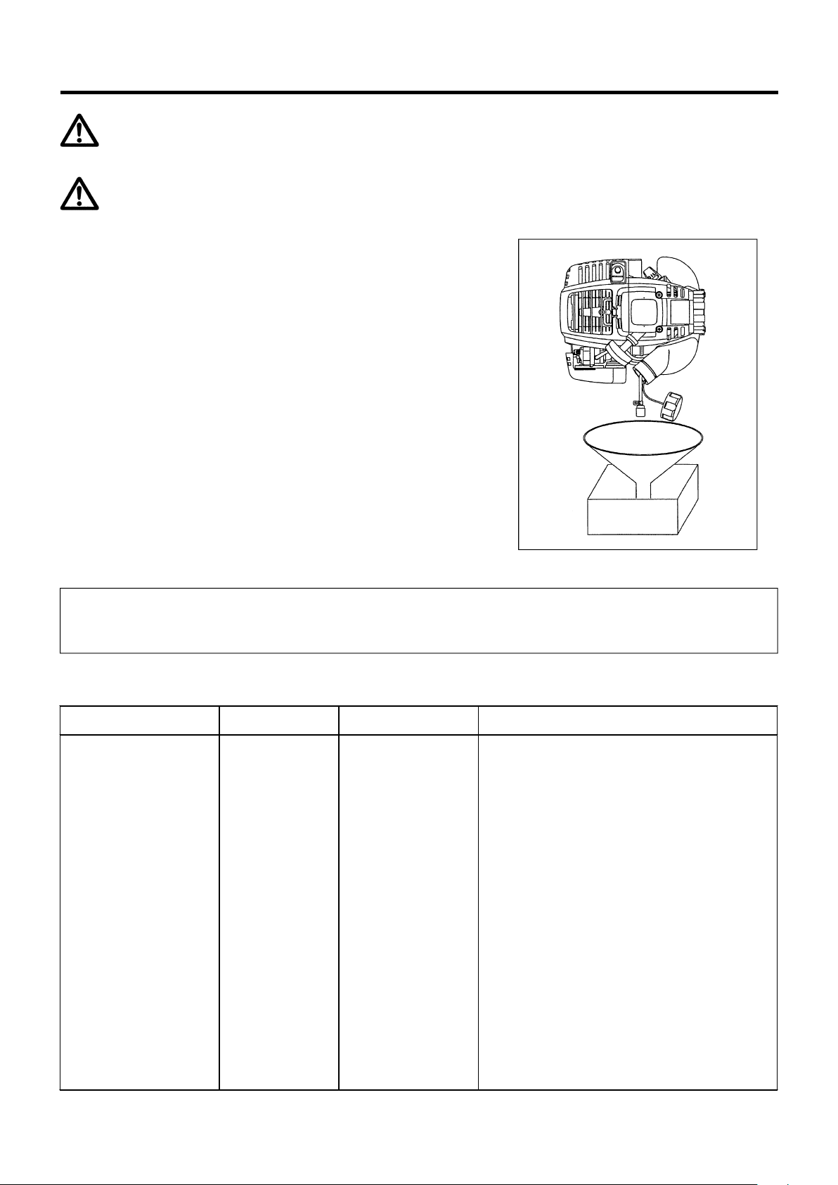
STORAGE
WARNING: When draining the fuel, be sure to stop the engine and confirm that the engine cools
down.
Just after stopping the engine, it may still hot with possibility of burns, inflammability and fire.
ATTENTION: When the machine is kept out of operation for a long time, drain up all fuel from the
fuel tank and carburetor, and keep it at a dry and clean place.
– Drain up fuel from the fuel tank and carburetor according to the following
procedure:
1) Remove the fuel tank cap, and drain fuel completely.
If there is any foreign matter remaining in the fuel tank, remove it
completely.
2) Pull out the fuel filter from the refill port using a wire.
3) Push the primer pump until fuel is drained from there, and drain fuel
coming into the fuel tank.
4) Reset the filter to the fuel tank, and securely tighten the fuel tank cap.
5) Then, continue to operate the engine until it stops.
– Remove the spark plug, and drip several drops of engine oil through the
spark plug hole.
– Gently pull the starter handle so that engine oil will spread over the engine,
and attach the spark plug.
– Attach the cover to the cutter blade.
– During storage, keep the rod horizontal or keep the machine upright with the
blade edge oriented upward. (In this case, pay full attention to prevent the
machine from falling.)
Never store the machine with the cutter blade edge oriented downward.
Lubricating oil may spill out.
– Keep the drained fuel in a special container in a well-ventilated shade.
Attention after long-time storage
– Before startup after long-time shutdown, be sure to replace oil (refer to P 17). Oil will deteriorate while the machine is kept out of
operation.
Fault location
Fault System Observation Cause
Engine not starting or with
difficulty
No ignition spark
Fuel supply Fuel tank filled
Compression
Mechanical fault Starter not engaging Broken starter spring, broken parts inside of the engine
Warm start problems
Engine starts but dies Fuel supply Tank filled Incorrect idling adjustment, carburetor contaminated
Ignition system Ignition spark O.K.
No compression when
pulled over
Tank filled ignition spark
existing
Fault in fuel supply or compression system, mechanical
defect
STOP-switch operated, wiring fault or short circuit, spark
plug or connector defective, ignition module faulty
Incorrect choke position, carburetor defective, fuel supply
line bent or blocked, fuel dirty.
Cylinder bottom gasket defective, crankshaft seals
damaged, cylinder or piston rings defective or improper
sealing of spark plug
Carburetor contaminated, have it cleaned
Fuel tank vent defective, fuel supply line interrupted,
cable or STOP-switch faulty
Insufficient performance
Several systems
may simultaneously
be affected
Engine idling poor
20
Air filter contaminated, carburetor contaminated, muffler
clogged, exhaust duct in the cylinder clogged
Page 21

Operating time
Item
Engine oil
Tightening parts
(bolt, nut)
Fuel tank
Inspect/clean
Before
operation
٤
Replace
Inspect
Clean/inspect
٤
٤
After
lubrication
Daily
(10h)
30h 50h 200h
Shutdown
/rest
13
*1
٤
17
19
Drain fuel
Corres-po
nding P
*3
٤
20
Throttle lever Check function
Stop switch Check function
Cutting blade Inspect
٤
٤ 12
Low-speed rotation Inspect/adjust
Air cleaner Clean
Ignition plug Inspect
Cooling air duct Clean/inspect
٤
15
٤
15
٤
16
٤
18
٤
18
٤
19
Inspect ٤ 19
Fuel pipe
Replace
Gear-case grease Refill
٤
19
*2
٧
Fuel filter Clean/replace ٤ 19
*2
Oil tube Inspect
Clearance between air intake
valve and air discharge valve
Adjust
Engine overhaul
٧
*2
٧
*2
٧
Carburetor Drain fuel
*3
٤
20
*1 Perform initial replacement after 20h operation.
*2 For the 200 operating hour inspection, request Authorized Service Agent or a machine shop.
*3 After emptying the fuel tank, continue to run the engine and drain fuel in the carburetor.
21
Page 22

TROUBLESHOOTING
Before making a request for repairs, check a trouble for yourself. If any abnormality is found, control your machine according to the description of
this manual. Never tamper or dismount any part contrary to the description. For repairs, contact Authorized Service Agent or local dealership.
State of abnormality Probable cause (malfunction) Remedy
Failure to operate primer pump Push 7 to 10 times.
Low pulling speed of starter rope Pull strongly.
Lack of fuel Feed fuel.
Clogged fuel filter Clean
Broken fuel tube Straighten fuel tube
Engine does not start
Engine stops soon
Engine speed does not increase
Cutter blade does not rotate
Stop engine immediately㩷
Deteriorated fuel
Excessive suction of fuel
Detached plug cap Attach securely
Contaminated spark plug Clean
Abnormal clearance of spark plug Adjust clearance
Other abnormality of spark plug Replace
Abnormal carburetor Make request for inspection and maintenance.
Starter rope cannot be pulled Make request for inspection and maintenance
Abnormal drive system Make request for inspection and maintenance
Insufficient warm-up Perform warm-up operation
Choke lever is set to “CLOSE” although engine
is warmed up
Clogged fuel filter Clean
Contaminated or clogged air cleaner Clean
Abnormal carburetor Make request for inspection and maintenance
Abnormal drive system Make request for inspection and maintenance
Loosened cutter blade-tightening nut Tighten securely
Twigs caught by cutter blade or
dispersion-preventing cover
Abnormal drive system Make request for inspection and maintenance.
Deteriorated fuel makes starting more difficult.
Replace with new one. (Recommended
replacement: 1 month)
Set throttle lever from medium speed to high
speed, and pull starter handle until engine
starts. Once engine starts, cutter blade
starts rotating. Pay full attention to cutter
blade.
If engine will not start still, remove spark plug,
make electrode dry, and reassemble them as
they originally are. Then, start as specified.
Set to “OPEN”
Remove foreign matter
Main unit vibrates abnormally.
Stop engine immediately㩷
Cutter blade does not stop immediately.
Stop engine immediately㩷
Engine does not stop.
Run engine at idling, and set choke
lever to CLOSE.
When the engine does not start after warm-up operation:
If there is no abnormality found for the check items, open the throttle by about 1/3 and start the engine.
㩷
Broken, bent or worn cutter blade Replace cutter blade
Loosened cutter blade-tightening nut Tighten securely
Shifted convex part of cutter blade and cutter
blade support fitting
Abnormal drive system Make request for inspection and maintenance
High idling rotation Adjust
Detached throttle wire Attach securely
Abnormal drive system Make request for inspection and maintenance
Detached connector Attach securely
Abnormal electric system Make request for inspection and maintenance.
Attach securely
22
Page 23
French
Nous vous remercions d’avoir porté votre choix sur une
débroussailleuse MAKITA. Cette débroussailleuse MAKITA est le
fruit d’un long programme de développement et de nombreuses
années d’expérience et d’accumulation de connaissances.
Lire attentivement ce manuel et suivre les instructions données. II
décrit en détail les divers points démontrant les exceptionnelles
performances de la débroussailleuse. Ceci vous permettra
d’obtenir les meilleurs résultats de cette débroussailleuse MAKITA.
Table of Contents Page
Symboles ..................................................................................... 23
Consignes de sécurité ............................................................ 24-27
Données techniques ................................................................... 29
Désignation des pièces ............................................................... 30
Montage moteur et arbre d’entrainement ................................ 31-32
Montage de la poignée ................................................................. 33
Montage du protecteur ................................................................ 33
Motage du couteau ...................................................................... 33
Avant mise en marche ............................................................ 34-35
Consignes de mise en marche et arret de la machine ............ 36-37
Aiguisage du couteau .................................................................. 37
Instructions relatives aux réparations .................................... 38-40
Remisage ................................................................................ 41-42
Guide de dépannage ................................................................... 43
SYMBOLES
La signification des symboles suivants est très importante pour la compréhension des instructions de ce manuel.
Lire attentivement ce manuel et
suivre les instructions données
Avertissement/Danger/Précoution
Interdit
Distance de sécurité
Danger de projection d’objets
Défence de fumer
Flammes vives interdites
Porter un casque de protection, des
protections visuelles et auditives
Vitesse maximale carburant et d’huile
Carburant (Essence)
Démarrage manuel du moteur
Arrêt d’urgence
Premiers secours
Recyclage
Porter des gants protecteurs
Réaction arrière
(pour la débroussailleuse uniquement)
Personnes et animaux interdits dans la
zone d’utilisation
SOUS TENSION/MA RCHE
HORS TENSION/A RRET
Logo de la CE
23
Page 24
CONSIGNES DE SÉCURITÉ
Consignes générales
– Lire attentivement ce manuel et suivre les instructions données
afin de se familiariser avec le maniement de la
d’ebroussailleuse. Ceci permettra d’utiliser correctement l’outil et
de travailler en sécurité. Un mauvais maniement de la
débroussailleuse par un utilisateur insuffisamment informé est
dangereux pour celui-ci et les personnes autour.
– Il est recommandé de ne pas prêter cette machine à des
personnes qui n’ont pas une expérience suffisante des
débroussailleuse. Toujours prêter le manuel d’instructions avec
la débroussailleuse.
– Utiliser la débroussailleuse uniquement si toutes ses protections
sont en place.
– Le premier utilisateur doit demander au revendeur de lui expliquer
le maniement de base d’une débroussailleuse à moteur.
– Les enfants et jeunes de moins de 18 ans ne doivent pas être
autorisés à utiliser la débroussailleuse. A partir de 16 ans, on
peut toutefois commencer à apprendre à I’utiliser, mais
uniquement sous la surveillance directe d’un instructeur qualifié.
– Utiliser la débroussailleuse avec les plus grandes précautions
et la plus grande attention.
– Ne pas utiliser la débroussailleuse si l’on n’est pas en parfaite
condition physique. Travailler consciencieusement et
prudemment. L’utilisateur doit être conscient de sa
responsabilité envers les autres.
– Ne jamais utiliser la débroussailleuse après avoir consommé de
l’alcoool ou pris des médicaments.
– Ne pas utiliser la débroussailleuse lorsqu’on est fatigué.
– Conserver ce manuel pour pouvoir le consulter ultérieurement.
Equipement de protection personnelle
– Les vêtements doivent être fonctionnels et adaptés. Ils doivent
être bien ajustés sans, toutefois, gêner les mouvements. Ne
pas porter de bijoux ou de vêtements qui pourraient se prendre
dans les broussailles ou les buissons. Si l’on a les cheveux
longs, les attacher.
– Afin de ne pas risquer des blessures à la tête, aux yeux,
auxmains et aux pieds ou des problèmes auditifs, porter
l’equipement et les vêtements protecteurs suivants lorsqu’on
utilise la débroussailleuse.
– Toujours porter un casque lorsqu’on travaille en forêt. Vérifier
régulièrement si le casque (1) n’est pas endommagé et le
remplacer au moins tous les 5 ans. N’utiliser qu’un casque
protecteur agréé.
– La visière (2) du casque ou des lunettes protectrices agréées
protègent les yeux et le visage contre les projections de
brindilles, pierres et autres objets. Lorsqu’on travaille avec la
débroussailleuse, toujours se protéger les yeux avec des
lunettes protectrices ou la visière du casque.
– Pour éviter des problèmes auditifs, porter un équipement
adéquat de protection contre le bruit (protège-oreilles (3),
protège-tympans, etc.), surtout en cas d’utilisation prolongée de
la débroussailleuse.
– Les combinaisons de travail (4) protègent le corps contre les
projections de pierres et les éclats de bois. Nous
recommandons vivement à l’utilisateur de porter une
combinaison de travail.
– Des gants spéciaux (5) en cuir épais font partie de I’equipement
prescrit et doivent toujours être portés pendant I’utilisation de la
débroussailleuse.
– Lors de l’utilisation de la débroussailleuse, toujours porter des
chaussures robustes (6) à semelle antidérapante. Ceci protège
contre les blessures et assure une bonne prise des pieds.
1
2
3
4
5
6
Mise en marche de la débroussailleuse
– S’assurer qu’il n’y a pas d’enfants ni d’autres personnes dans
un rayon de 50 pieds ou 15 mètres, et veiller également à ce
qu’il n’y ait pas d’animaux à proximté.
– Avant l’utilisation, toujours vérifier les points suivants
afin d’assurer la sécurité :
S’assurer que le couteau est bien fixé. Vérifier que I’écrou de
montage du couteau est serré à fond. S’assurer que la manette
des gaz est facile à manoeuvrer et que son mouvement est
régulier. S’assurer que le verrou de la manette des gaz
fonctionne correctement. Le couteau ne doit pas tourner
lorsque le moteur fonctionne au ralenti. Se reporter aux
instructions de réglage du ralenti à la page 37.
S’assurer que les poignées sont propres et sèches et vérifier le
fonctionnement de d’arrêt. Veiller à ce que de l’huile ou du
carburant ne vienne pas sur les poignées.
– Avant le travail, vérifier la réglementation locale relative au
niveau sonore et aux heures d’utilisation et la respecter.
– Ne mettre la débroussailleuse en marche que lorsqu’elle est
posée sur le sol.
– Ne pas la mettre en marche lorsqu’elle est retournée sur le dos.
24
Page 25
Mettre la débroussailleuse en marche en suivant rigoureusement
les instructions.
N’utiliser que la méthode indiquée pour mettre le moteur en marche.
– N’utiliser la débroussailleuse et les outils fournis que pour les
applications indiquées.
– Ne mettre le moteur de la débroussailleuse en marche qu’après
avoir terminé tout le montage de l’outil. L’utilisation de la
débroussailleuse n’est autorisée qu’une fois que tous les
accessoires appropriés ont été montés.
– Avant la mise en marche, s’assurer que le couteau ne viendra
pas en contact avec des objets tels que branches ou pierres.
– En cas de problème du moteur, l’arrêter immédiatement.
– Si le couteau heurte des pierres ou d’autres objets, arrêter
immédiatement le moteur et contrôler le couteau.
– Vérifier fréquemment si le couteau n’est pas endommagé.
Vérifier s’il n’est pas fêlé en donnant de petits coups sur le
couteau et en écoutant le bruit produit.
– On doit entendre un tintement familier.
– N’utiliser la débroussailleuse qu’aprés avoir attaché le harnais.
Régler correctement la longueur du hrnais avant de mettre la
débroussailleuse en marche. Pour éviter la fatigue ou une perte
de contrôle de l’outil, il est important que le harnais soit ajusté à
la taille de l’utilisateur. Ne jamais tenir la débroussailleuse d’une
seule main pendant l’utilisation.
– Pendant l’utilisation, toujours tenir la débroussailleuse des deux
mains.
Veiller à avoir toujours une bonne prise des pieds.
– Utiliser la débroussailleuse d’une manière telle que l’on ne
respire pas les gaz d’echappement. Ne jamais faire fonctionner
le moteur dans un local clos (risque d’asphyxie et d’intoxication
par les gaz). Le monoxyde de carbone est un gaz inodore.
Veiller à ce que l’aération soit toujours suffisante.
– Arrêter le moteur avant de faire une pause et de laisser la
débroussailleuse sans surveillance. Placer la débroussailleuse
dans un endroit où ils ne présentent pas de danger pour les autres
et où ils ne risquent pas d’enflammer des matières combustible ou
d’être endommagés.
– Ne jamais poser la débroussailleuse sur de l’herbe sèche ou
sur des matières combustibles.
– Le couteau doit toujours être utilisé avec le protecteur
approprié. Ne jamais utiliser le couteau sans son protecteur.
– Durant le fonctionnement, tous les protecteurs et autres pièces
de protection foumis avec la débroussailleuse doivent être
utilisés.
– Ne jamais faire fonctionner le moteur avec un pot
d’échappement défectueux.
– Arréter le moteur avant de transporter la débroussailleuse.
– Pour un long transport, toujours utiliser le protecteur d’outil foui
avec la débroussailleuse.
– Pour transporter la débroussailleuse dans une voiture ou un
camion, les placer à la verticale et les fixer de façon à éviter
tout dommage.
– Avant de transporter la débroussailleuse, s’assurer que le
réservoir est complètement vide pour éviter toute fuite de
carburant.
•Interruptions de travail
•Transport
•Plein de carburant
•Maintenance
•Remplacement d’outil
Renouvellement du carburant
– Pour éviter tout risque d’incendie et de brûlure, manipuler le
carburant avec précaution. Il est hautement inflammable.
– Avant de transporter la débroussailleuse, arrêter le moteur.
– Eviter le contact des produits pétroliers avec la peau. Ne pas
respirer les vapeurs de carburant. Toujours porter des gants
protecteurs lorsqu’on fait le plein du réservoir. A intervalls
reguliers, changer de vêtements protecteurs et les faire nettoyer.
– Veiller à ne pas souiller le sol avec du carburant ou de l’huile.
Laisser sécher les chiffons avant de les jeter. Les jeter dans un
récipient approprié muni d’un couvercle pour qu’ils ne puissent
pas s’enflammer spontanément. Toujours essuyer l’outil au sec
avant de mettre le moteur en marche.
– Veiller à ne pas renverser de carburant sur les vêtements. Si
du carburant vient sur les vêtements, se changer
immédiatement (danger de mort).
– S’assurer régulièrement que le bouchon du réservoir est serré à fond.
– Serrer avec soin la vis de verrouillage du réservoir. Changer
d’endroit avant de mettre le moteur en marche (à une distance
d’au moins 10 pieds ou 3 mètres de l’endroit où l’on a fait le plein).
– Ne jamais faire le plein dans un local clos. Les vapeurs de
carburant s’accumulent au niveau du sol (risque d’explosion).
– Ne transporter et ne stocker le carburant que dans des
récipients agréés. S’assurer que la réserve de carburant est
hors de portée des enfants.
– Ne pas faire le plein lorsque le moteur est chaud ou qu’il toume.
– L’essence utilisée (mélangée avec de l’huile moteur deux temps)
ne doit contenir ni éthanol ni méthanol (types d’alcool). Ceci a pour
but de protéger les canalisations et les autres pièces du moteur.
3m(10FT)
25
Page 26
Méthode d’utilisation
– N’utiliser la débroussailleuse qu’avec un éclairage et une
visibilité suffisants. En hiver, prendre garde aux endroits
glissants ou mouillés, à la glace et à la neige (risque de glisser).
Veiller a avoir toujours une bonne prise des pieds.
– Ne pas présumer de ses forces. Garder toujours une bonne
prise des pieds, un bon équilibre et un bon contrôle de la
débroussailleuse.
– Ne jamajs couper des ceintures.
– Ne jamais monter sur un arbre pour effectuer une opération de
coupe avec la débroussailleuse.
– Ne jamais travailler sur une surface instable ou un terrain très
en pente.
– Enlever des objets tels que, les pierres, les clous, gazon etc.,
de la zone de travail. De tels objets risquent d’endommager le
couteau et de provoquer des réactions arrière dangereuses. Ils
peuvent également être projetés.
– Avant de commencer à couper, veiller à ce que le couteau ait
atteint la vitesse normale de travail.
– Ne jamais utiliser la débroussailleuse à l’envers ou avec une
inclinaison excessive.
– ATTENTION! — La partie du couteau reste dangereuse
lors de la décélération de la machine précédant l’arrêt.
Réaction arrière
– Lors de l’utilisation de la débroussailleuse, il peut se produire
une réaction arrière incontrôlée.
– Ceci est particulièrement vrai si l’on essaie de couper avec le
secteur du couteau compris entre 12 et 2 heures Iorsqu’on
regarde depuis la position de l’utilisateur.
– Ne jamais mettre ce secteur du couteau en contact avec des
objets tels que buissons, souches, arbrisseaux, etc., de plus de
3 cm de diamètre.
– La débroussailleuse serait alors déviée brutalement et avec
force et risquerait de provoquer des blessures graves.
– Ne jamais essayer de couper avec le secteur du
couteau compris entre 12 et 2 heures.
Prévention de la réaction arrière
Pour éviter une réaction arrière, respecter les consignes
suivantes :
– Une utilisation dans le secteur du couteau compris entre 12 et 2
heures peut être très dangereuse, tout particulièrement avec
des couteaux en métal.
L’utilisation dans le secteur du couteau entre 11 et 12 heures, et
entre 2 et 5 heures présente aussi un certain risque de réaction
arrière.
– Des opérations de coupe dans le secteur du couteau compris
entre 11 et 12 heures, et entre 2 et 5 heures ne doivent être
effectuées que par des utilisateurs entraînés et expérimentés,
et ce à leurs propres risques. Il est possible de travailler
facilement presque sans aucune réaction arrière dans le
secteur du couteau compris entre 8 et 11 heures.
12
2
Attention :
Réaction arrière
Figure schématique
Figure schématique
Outils de coupe
Utiliser uniquement les outils de coupe corrects pour procéder aux
travaux.
Couteau (couteau à 4 dents, couteau à 8 dents)
Pour couper les matériaux épais, comme les mauvaises herbes,
hautes herbes, buissons, arbustes, sous-bois, fourrés, fourrés,
etc. (diamètre maximal de 2 cm). Pour de genre de travaux,
déplacer la débroussailleuse en demi-cercles réguliers, de droite à
gauche (comme avec une faux).
Instructions de maintenance
– Avant de commencer à travailler, vérifier l’état de la
débroussailleuse et en particulier celui du couteau, de son
protecteur et du harnais. Prêter une attention particulière aux
lames du couteau qui doivent être correctement aiguisées.
– Avant de remplacer ou d’aiguiser le couteau ou de nettoyer la
débroussailleuse ou l’outil de coupe, arrêter le moteur et retirer
les connecteurs des bougies.
26
Page 27
Ne jamais essayer de redresser ou souder des couteaux
endommagés.
– Etre attentif à l’environnement. Utiliser la débroussailleuse avec
le minimum de bruit et de pollution possible. Veiller tout
particulièrement à ce que le réglage du carburateur soit correct.
– Nettoyer régulièrement la débroussailleuse et s’assurer que
tous les écrous et vis sont bien serrés.
– Ne jamais procéder à une opération d’entetin ou remiser la
débroussailleuse à proximité de flammes vives, étincelles, etc.
– Toujours remiser la débroussailleuse dans un local fermé à clé
et bien aéré après avoir vidé le réservoir.
Observer les règles sur la prévention des accidents
prescrites par les associations commerciales
concernées et par les compagnies d’assurances.
N’effecture aucune modification sur la débroussailleuse
car ceci pourrait rendre son utilisation dangereuse.
L’entretien ou les réparations pouvant être effectués par
l’utilisateur se limitent aux opérations indiquées dans ce manuel
d’instructios. Toute autre opération doit être confiée à un agent de
service aprèsvente agréé.
N’utiliser que des pièces de rechange et des accessoires d’origine
fournis par MAKITA. L’utilisation d’accessoires et d’outils non
agréés augmente les risques d’accident et de blessures. MAKITA
décline toute responsabilité pour des accidents ou des dommages
causés par l’utilisation d’outils de coupe ou accessoires non
agréés.
Premiers secours
Pour être paré en cas d’accident, prévoir une trousse de premiers
de secours à proximité des opérations de coupe. Remplacer
immédiatement tout article pris dans la trousse de premiers secours.
Lorsqu’on demande de l’aide lors d’un accident, fournir
les informations suivantes :
– Lieu de l’accident
– Circontstances de l’accident
– Nombre de blessés
– Type de blessuresèra
– Nom de la personne qui appelle
Emballage
La débroussailleuse MAKITA est livrée dans deux cartons qui la
protègent contre les dommages pendant le transport. Le carton
est une matière primi de base et peut être réutilisé ou recyclé
(recyclage des vieux papiers).
27
Page 28

DECLARATION DE CONFORMITE CE
Modèle : EBH341R
Nous prenons la responsabilité pour déclarer que le présent produit est conforme aux normes suivantes
énoncées aux documents ISO14865, ISO14740, EN55012 conformément aux Drectives du Conseil, 89/392/
CEE, 98/37/CEE, 93/68/CEE, 89/336/CEE modifiées et 92/31/CEE modifiée.
Niveau sonore mesuré : 108.4 dB
Niveau sonore garanti : 113.3 dB
Niveaux sonores mesurés conformément à la Directive du Conseil, 2000/14/CE.
Procédure d’évaluation de conformité : Annexe V
CE2007
Tomoyasu Kato
Directeur
Producteur responsable:
Makita Corporation.
3-11-8, Sumiyoshi-cho, Anjo, Aichi, JAPAN
Représentant autorisé en Europe:
Makita International Europe Ltd.
Michigan Drive, Tongwell, Milton Keynes, Bucks MK15 8JD, ENGLAND
28
Page 29

DONNÉES TECHNIQUES
Modèle
Dimensions : longueur x largeur x hauteur (carter du tube) mm
Poids (sans protecteur en plastique et couteau) kg
Volume (réservoir) L
Accessoire de coupage (diam. de la lame de coupage) mm
Cylindrée du moteur cm
Puissance maximale du moteur kw
Régime moteur à la vitesse maximale de broche recommandée
min
Vitesse maximale de broche (correspondante) min
Consommation de carburant kg/h
Consommation spécifique de carburant g/kwh
EBH341R
Poignée simple
Lame de coupe Tête de coupe à fil
430 x 280 x 430
10.2
0.65
255
3
-1
-1
33.5
1.07 a 7000 min
10000
7500
-1
0.458
426
Régime de ralenti min
Vitesse d'embrayage min
Carburateur (carburateur à diaphragme) type
Système d'injection type
Bougie d'allumage type
Jeu électrodes mm
Marche à vide m/s
Emballement ou papilion des
gaz ouvent à fond m/s
Marche à vide m/s
Emballement ou papilion des
Vibration
selon
ISO 7916
Poignée droite
(prise arrière)
1)
Poignée gauche
(prise avant)
gaz ouvent à fond m/s
Moyenne du niveau de pression acoustique selon ISO 7917
Moyenne du niveau de puissance sonore selon ISO 10884
1)
dB
1)
dB
Carburant
-1
-1
3000
4100
WALBRO WYL
Type Allumage électronique
NGK CMR6A
0.7 – 0.8
2
2
2
2
0.6 0.7
4.0 5.59
0.85 0.82
4.78 8.12
89.3 97.1
104.3 108.4
Essence pour moteur
Huile pour moteur
huile de la classification API, classe SF ou supérieure
(moteur à quatre temps pour automobile)
SAE 10W- 30
Rapport d'engrenage
1) Ces donnée tiennent également compte des modes de fonctionnement au ralenti et à plein régime ou pleins gaz.
15/20
29
Page 30
DÉSIGNATION DES PIÈCES
ԣ
Ԟ
ԛ
ԥ
Ԡ
Ԝ
Ԥ
ԣ
ԩ
Ԩ
ԧ
Ԧ
Ԛ
Ԙ
Ԣ
ԙ
Ԣ
ԡ
ԝ
ԟ
Ԫ
ԫ
F Nomenclature des pièces
Réservoir de carburant
1
Poulie d'enroulement du câble
2
de démarrage
Filtre à air
3
Interrupteur I-O (marche/arrêt)
4
Bougie d'allumage
5
Protection d'échappement
6
Poignée
7
Levier de commande
8
Câble de commande
9
Arbre
10
Dispositif de protection
11
Carter de boîte de vitesse
12
Lame de coupe
13
14 Harmais
15
Bouchon de réservoir
Poignée lanceur
16
Pompe primare
17
Levier d’étranglement
18
Pot d’échappement
19
Jauge d’huile
20
21 Tube flexible
22 Tête de coupe à fil
30
Page 31

MONTAGE MOTEUR ET ARBRE D’ENTRAINEMENT
ATTENTION : Avant toute intervention sur la
ATTENTION : Ne mettre la débroussailleuse en marche
1. En joignant le tube flexible au moteur et au carter du
tube.
Introduire un bout du tube flexible dans le carte d’embrayage du
moteur jusqu’à ce qu’il soit bloqué avec son sec.
Introduire l’autre bout du tube flexible dans le carter du tube de
la débroussailleuse jusqu’au blocage.
On peut changer chaque bout du tube flexible.
Vérifier que l’extremité carrée de l’arbre flexible est appropiée
au joint de l’abre d’entraînement.
Attention : S’il vous semble difficile de mettre le tube
débroussailleuse, toujours arréter le
moteur et débrancher les connecteurs des
bougies. Faire attention aux pièces chaudes
du moteur et à la lame du couteau. Toujours
porter des gants protecteurs.
qu’après l’avoir complètement montée.
flexible proprement, l’extremité carrée de
l’arbre flexible ne peut forcément pas
toucher le joint de l’arbre d’entraînement. Il
ne faut pas pousser pour éviter du
dommage de l’extremité de l’arble flexible.
Répéter la même procedure jusqu’à ce qu’il
se conviennent.
2. Montage du câble de commande
– Déposer le couvercle du filter d’air.
– Poser le câble de commande (4) dans le boulon de réglage (5),
et déplacer l’émerillon (6) pour que le câble puisse entrer dans
la rainure de l’émerillon. En même temps, le côté trou rond de
l’émerillon sera orienté vers la ferrure à l’extrémité du fil
intérieur.
– Lâcher l’émerillon, et confirmer que la ferrure à l’extrémité du fil
intérieur soit posée dans le trou.
– Poser le couvercle du filtre d’air.
㩷
㩷
(4)
Câble de
commande
(5)
Trou rond
(6)
Émerillon
Insér㪼
Ferrure d’extrémité
31
Page 32

RACCORDEMENT DU CORDON D’INTERRUPTEUR
– Raccorder les cordons de l’interrupteur avec les cordons
venant du moteur en insérant l’uus dans les autres.
– Fixer le raccord de l’interrupteur avec l’agrafe (7).
REGLAGE DU CÂBLE DE COMMANDE
Régler le câble de commande avec boulon de réglage pour que il
puisse avoir un jeu de 1 à 2 mm lorsque le levier d’étranglement
est mis à la position de petite vitesse au moyen du boulon de
réglage du carburateur. (Prendre garde que la lame de coupe ne
tourne pas au ralenti.)
㩷
(7)
㩷
1-2 mm
Laisser le câble de commande et les câbles de I’interrupteur I-O
aller dans le tube flexible et fixer les trois points à fond sur
I’attache (8). Si le câble de commande et les câbles de
I’interrupteur I-O ne sont pas fixés, Il y a lieu de craindre qu’ils
s’accrochent dans les branches ou autre, ce qui serait
dangereux.
32
Page 33

MONTAGE DE LA POIGNÉE
– Fixer une barrière sur le côté gauche de la débroussailleuse
avec la poignée pour la securité de l’utilisateur.
– Ne pas approcher la poignée simple à la poignée de commande.
Maineir la position entre la poignée simple et la poignée simple à
plus de 25 cm.
(Un collier d’écartement est prévu à cet effet.)
MONTAGE DU PROTECTEUR
Afin de se conformer aux dispositions de sécurité applicables, on
ne doit utiliser que les combinaisons d’outil/protecteur indiquée
dans le tableau. L’utilisateur et les personnes autour seraient
autrement exposés à de graves blessures ou à un danger de
mort.
Utiliser exclusivement un couteau ou une tęte de coupe à
fil MAKITA d’origine.
– Le couteau doit être propre, bien aiguisé et ne pas comporter de
fêlures ou cassures.
Si le couteau heurte une pierre ou un autre objet dur lors de
l’utilisation, arrêter le moteur et vérifier immédiatement la lame.
– Nettoyer, aiguiser ou remplacer le couteau toutes les trois
heures d’utilisation.
– Le diamètre extérieur du couteau ne doit pas dépasser 255 mm
(10-1/32”). Ne jamais utiliser un couteau dont le diamètre
extérieur est supérieur à 255 mm (10-1/32”).
ATTENTION :Pour la sécurité de l’utilisateur et le respect
– Fixer une protection sur le réducteur à I’aide de 4 vis serrées à
l’aide de 4 vis serrée à fond.
Ne jamais utiliser la débroussailleuse sans protection ou avec
une protection cassée.
de la réglementation sur la prévention des
accidents, le protecteur approprié doit
toujours être en place. L’utilisation de la
machine sans le protecteur n’est pas
autorisée.
Au moteur
Couteau à 4 dents
Pièce NO.
6418501400
Tête de coupe à fil
Pièce NO.6348003000 Pièce NO.174345800
Couteau à 8 dents
Pièce NO.
6418501900
Protecteur pour
couteau métallique
Pièce NO.
6118502000
MONTAGE DE LA COUTEAU OU DE
LA TÉTE DE COUPE À FIL
Tourner la machine à l’envers. Le couteau ou tête de coupe à fil
peut alors être remplacé facilement.
Montage de la couteau
– Préparer un couteau et d’autres piéces en ordre comme indiqué
sur le schema. Introduire une barre ou une clé torx six pans
dans un trou du carter jusqu’à ce que le couteau soit bloqué et
ne toumrnera plus.
Serrer l’écrou en le tournant dans le sens contraire aux aiguilles
d’une montre avec la combinaison-clé. (Vérifier que l’écrou est
bìen serré ou desserré dans la direction opposée de l’écrou
usuel.)
– L’écrou doit être re-serré chaque fois avant de l’utiliser.
– Pour cette débroussailleuse, nous vous recommandons des
attachements comme indiqué à la droite.
– Ne jamais couper des arbres, des búches, des boìs ou d’autres
objets solides.
[Couple de serrage : 28 㧙 48 N-m]
NOTA :Toujours porter des gants pour manipuler le
couteau.
Montage de la tęte de coupe coupe à fil
– La couvercle pour le couteau, la couvercle pour le vis et l’écrou
ne sont pas nécessaires pour monter la tête de coupe à fil. La
tête de coupe à fil doit se situer au sommet de la couvercle pour
des herbes.
– Insérer la clé torx six pans par le trou dans la boîte à
engrenages et faire tourner la support du couteau jusqu’à ce
qu’elle soit fixée par clé torx six pans.
– Ensuite, visser la tête de coupe à fil sur l’arbre, en la faisant
tourner en sens direct.
– Enlever la clé torx six pans.
écrou
couvercle
pour le vis
couvercle pour
le couteau
couteau
couvercle pour
des herbes
support du
couteau
plaque
protectrice
Protection
réducteur
33
Page 34

AVANT MISE EN MARCHE
CONTROLE ET RAVITAILLEMENT DE L’HUILE MOTEUR
– Faire la méthode suivante après avoir vérifié que le moteur refroidit.
– Maintenir le moteur en position et en lever, la jauge d’huile afin de vérifier que le niveau est situe entre les repères inférieur et supérieur.
Lorsque l’huile devient insuffisante en telle manière que la jauge la touche seulement par son extrémité, en particulier lorsque la jauge reste
insérée dans le carter sans vissage (Fig. 1), ravitailler en huile nouvelle (Fig.2).
– A titre de renseignement, la durée de revitaillement est d’environ 15 h (fréquence de ravitaillement : 15 fois).
– Si l’huile varie en couleur ou contient des impuretés, il faut la remplacer. (Pour l’intervalle et la méthode de remplacement, se référer à la
page 38.)
Huile recomm andée : SAE 10W – 30 huile de la classification API, classse SF ou supérieure (moteur à quatre temps pour automobile)
Volume d ’huile : Env. 0.1 L
Nota: Si le moteur n’est pas debout, l’huile peut se déplacer aux alentours du moteur, et elle peut être ravitaillée excessivement.
Si l’huile est furnie au-dessus de la limite, l’huile peut être contaminée ou elle peut prendre feu, emettant une fumée blache.
Remplacement de l’huile “Jauge d’huile”
– Enlever les poussières et les impuretés à proximité de l’orifice de ravitaillement, et déposer la jauge d’huile.
– Tenir la jauge d’huile déposée libre de sable et de poussière. Le sable ou la poussière adhérant à la jauge d’huile peuvent causer une
circulation irrégulière ou abrasion sur les pièces du moteur.
– A titre d’exemple, pour maintenir la jauge nette, il est recommandé d’insérer la jauge d’huile sur le côté poignée dans le couvercle de
moteur, comme l’indique Fig. 3.
(1) Tenir le moteur à niveau, et déposer la jauge d’huile.
(2) Mettre de l’ huile jusqu’au bout de l’orifice de ravitaillement. (Se référer à la
figure de la page précédante.)
Mettre de l’huile a l’aide récipient de ravitaillement en lubrifiant.
(3) Serrrer fermement la jauge d’huile. Un serrage insuffisant causera une fuite
d’huile.
Si l’huile adhère autour de
ce bout, ravitailler en huil e.
Fig.1 Fig.2 Fig.3
L’essentiel 2 lors de remplacement de l’huile: “Si de l’huile se renverse”
– Si de l’huile se renverse entre le réservoir à carburant et le groupe moteur, l’huile est aspirée en dedans par l’orifice d’entrée d’air
refroidissant, ce qui salira le moteur. Ne jamais oublier d’essuyer l’huile renversée avant commencement de la marche.
Limite supérieur du niveau d’huile
(Partie supérieure de l’orifice de
ravitaillement d’huile (partie filtée)
Jauge d’huile
㩷
34
Page 35

RAVITAILLEMENT
Manipulation du carburant
Il est nécessaire de manipuler le carburant avec un soin particulier. Le carburant peut contenir des matières similaires aux solvants. Le
ravitaillement doit être fait dans une chambre bien ventilée ou en plein air. Ne jamais aspirer de la vapeur de carburant, et s’éloigner du
carburant. Un contact prolongé ou régulier avec de l’essence pout provoquer un dessèchement de la peau ainsi que des maladies et des
réactions allergiques. En cas de contact avec les yeux il faut rincer avec de l’eau. Si l’oeil reste irrité consulter un médecin.
Durée de stockage du carburant
– Le carburant doit être utilisé totalement dans un délai de quatre semaines, même s’il est contenu dans un récipient spécial et stocké à
l’ombre bien aérée.
– Si le carburant n’est pas stocké dans un récipient spécial ou si le récipient n’est pas couvert, le carburant se détériore dans un jour.
ENTREPÔSAGE DE L’APPAREIL ET DU RÉSERVOIR DE RAVITALLEMENT
– Garder l’appareil et le réservoir à un endroit sans être exposé aux rayons du soleil.
– Ne jamais garder le carburant dans une cabine ou sur le camion.
Carburant
Le moteur est à quatre temps. Utiliser de l’essénce sans plomb 98.
Les essentiels pour le carburant
– Ne jamais utiliser de mélange d’essence contenant de l’huile à moteur.
– Une huile détériorée causera un démarrage irrégulier.
Ravitaillement
Avertissement : produit inflammable
Essence utilisée : Essence sans plomb 98
– Desserrer un peu le bouchon de réservoir de telle maniére qu’il n’y ait pas de
différence en pression atmosphérique.
– Déposer le bouchon de réservoir, et ravitailler, l’orifice de ravitaillement
orienté en dessus. (Ne jamais ravitailler en carburant pleinement jusqu’ à
l’orifice.)
– Essuyer complètement les alentours du bouchon de réservoir afin de prévenir
l’entrée de matières étrangères dans le réservoir à carburant.
– Après ravitaillement, serrer fermement le bouchon de réservoir.
• S’il y a aucune fissure sur le couvercle du réservoir, le remplacer.
• Le couvercle du réservoir est une pièce consomptible. Par conséquent,
elle doit être remplacé tous les deux à trois ans.
Bouchon de réservoir à carburant㩷
Limite supérieure
du carburant
㩷
Réservoir à
carburant
㩷
35
Page 36

CONSIGNES DE MISE EN MARCHE ET ARRET DE LA MACHINE
Respecter les lois applicables en matière de prévention contre les accidents!
Démarrage
Déplacer la machine à trois mètres au moins du lieu de ravitaillement. Placer la débroussailleuse sur une zone propre en veillant à ce que
l'outil de coupe n'entre pas en contact avec le sol ou tout autre objet.
A:Démarrage à froid
1) Positionner cette machine sur un lieu plat.
2) Mettre l’interrupteur I-O (1) sur la position “MARCHE”.
3) Fermer le levier de starter.
– Fermer le levier de starter lors d’un démarrage à froid.
– Ouverture de levier starter pour un démarrage à chaud..
4) Pompe d’amorçage
Continuer à pousser la pompe d’amorçage jusqu’à ce que le carburant entre
dans la pompe d’amorçage. (En général, le carburant entre dans la pompe
d’amorçage par 7 à 10 poussées.)
Si la pompe d’amorçage est poussée excessivement, un excès de l’essence
retourne au réservoir à carburant.
5) Poulie d’enroulement du câble de démarrage
– Tirer la poignée de démarrage jusqu’à ce qu’il soit difficile de tirer (point
de compression). Puis, laisser revenir la poignée de démarrage, et la tirer
fortement.
– Ne jamais tirer le câble pleinement. Une fois que la poignée de
démarrage est tirée, ne jamais lâcher prise du câble tout à coup. Saisir la
poignée de démarrage jusqu’à ce qu’elle retourne au point original.
6) Levier de starter
Lorsque le moteur démarre, ouvrir le levier de starter.
– Ouvrir le levier de starter pas à pas, en vérifiant la marche du moteur.
Ne pas manquer d’ouvrir le levier de réglage pleinement à la fin.
– A froid ou lorsque le moteur reste froid ne pas ouvrir le levier de réglage
subitement. Autrement, le moteur s’arrêtera.
7) Montée en température
Effectuer la montée en température pendant deux ou trois minutes.
㩷
㩷
㩷
㩷
MARCHE
Levier de déblocage
Interrupteur I-O (1)
Levier
d’étranglement (6)
FERMER
Carburateur
Pompe d’amorçage
OUVRIR
36
Page 37

Attention:− Si vous actionnez trop longtemps sur le starter alors que la manette de démarrage est en position “CLOSE”, vous risquez de noyer
V
le moteur par une arrivée trop importante de carburant, rendant le démarrage de l’apparell difficile.
− Si le moteur est noyé, dévissez la bougie, puis tirez largement plusieurs fois sur la poignée de démarrage, et retirez le carburant en
trop. Ou bien, séchez l’électrode de la bougle.
Consignes de sécurité lors du fonctionnement:
Si le lever d’étranglement est complètement ouvert lors d'un fonctionnement sans charge, le régime du moteur augmente jusqu'à 10000 /min ou
plus. Ne jamais utiliser le moteur à une vitessee supérieure à la vitesse requise et respecter une vitesse approximative de 6000 – 8500 /min.
B: Démarrage après réchauffage
1) Pousser la pompe d’amorçage à plusieurs reprises.
2) Tenir le levier d’étranglement au ralenti.
3) Tirer le câble de démarrage fortement.
4) S’il est difficile de démarrer le moteur, ouvrir le levier d’étranglement d’un tier. Il faut alors faire attention à la lame de coupe, qui peut tourner
soudainement.
Attention lors du fonctionnement
Lorsque le moteur fonctionne à l’envers, il peut arriver qu’une fumée blanche s’échappe.
Arrêt
1) Relâcher complètement le levier d’accélérateur (6) et mettre l’interrupteur
I-O sur la position “STOP” lorsque le régime du moteur s'est abaissé: le
moteur s'arrêtera.
2) Faire attention à ce que la tête de coupe ne puisse pas s’arrêter toute de
suite, faire réduire doucement la vitesse jusqu’au ralenti.
ARRET
Interrupteur I-O (1)
Levier
d'étranglement (6)
REGLAGE DE LA MARCHE A PETITE VITESSE (AU RALENTI)
Lorsqu’il est nécessaire de faire un réglage à petite vitesse (au ralenti), manipuler la vis régulatrice du carburateur.
VERIFICATION DE LA ROTATION A PETITE VITESSE
– Régler à 3000 /min la rotation à petite vitesse.
S’il est nécessaire de changer la vitesse de rotation, ajuster la vis régulatrice
avec tournevis cruciforme.
– Tourner la vis régulatrice à droite. La rotation du moteur augmentera.
– Tourner la vis régulatrice à gauche. La rotation du moteur alors diminuera.
– Le carburateur est réglé en générale avant expédition. S’il est nécessaire de
le régler de nouveau, s’adresser à l’agent du service après-vente habilité.
㩷
Carburateur
is régulatrice
㩷
AIGUISAGE DU COUTEAU
ATTENTION : L’aiguisage des couteaux indiqués ci-dessous ne
– Couteau (couteau à 4 dents, couteau à 8 dents)
Les agents de service après-vente agréés peuvent fournir un service
d’aiguisage et d’équilibrage spécialisé.
NOTA : Pour augmenter la durée de service du couteau (couteau à
doit être effectué que dans un centre agrée. Un
aiguisage manuel déséquilibrerait l’outil de coupe et
entraînerait des vibrations et des dommages de la
machine pouvant être dangereux.
4 dents, couteau à 8 dents), on peut le retourner à l’envers
une fois jusqu’à ce que les deux arêtes soient émoussées.
Ne pas utiliser une lame émousée. Ceci pourrait entraîner
une réaction arrière et de graves blessures.
37
Page 38

INSTRUCTIONS RELATIVES AUX RÉPARATIONS
ATTENTION: Toujours couper le moteur et retirer le capuchon de la bougie d'allumage avant de procéder à tout travail sur la débroussailleuse
(voir “Contrôle de la bougie d'allumage"). Toujours porter des gants de protection!
Procéder aux réparations suivantes à intervalles réguliers pour assurer une longévité importante et pour éviter tout endommagement de
l'équipement.
Contrôle et opérations de maintenance réguliers
– Vérifier si les vis sont serrées et si l'ensemble des pièces est en place avant d'utiliser la machine. Prêter particulièrement attention à la
fixation de la lame de coupe ou de la tête de coupe.
– Toujours vérifier si le canal et les ailettes de refroidissement du cylindre sont débouchés avant d'utiliser la machine.
Les nettoyer si nécessaire.
– Procéder quotidiennement aux opérations suivantes après utilisation:
• Nettoyer l'extérieur de la débroussailleuse et vérifier si elle est endommagée.
• Nettoyer le filtre à air. Nettoyer le filtre plusieurs fois par jour si les conditions de travail sont extrêmement poussiéreuses.
• Vérifier si la lame ou la tête de coupe est endommagée et s'assurer qu'elle est montée solidement.
• Vérifier que la différence entre la vitesse de ralenti et la vitesse de conduite est suffisante afin de s'assurer que la lame de coupe est au
repos lorsque le moteur fonctionne ralenti (réduire la vitesse de ralenti si nécessaire).
Si l'outil devait continuer à fonctionner dans des conditions de ralenti, consulter l'agent du service après-vente habilité le plus proche.
– Vérifier le fonctionnement de l'interrupteur I-O, le levier de déverrouillage, le levier de commande et le bouton de verrouillage.
REMPLACEMENT DE L’HUILE A MOTEUR
Une huile à moteur détériorée peut diminuer la longévité considérablement. Ne pas manquer de vérifier la période et la quantité de
remplacement.
ATTENTION : En général, le bloc moteur et l’huile à moteur restent chauds immédiatement après que le moteur s’arrête. Lors de
Nota: Si l’huil est fournie au-dessus de la limite, ell peut être contaminée ou prendre feu.
Intervalle de remplacement : Initalement, toutes les 20 heures de marche, et successivement toutes les 50 heures de marche.
Huile recommandée : SAE10W-30 de la classification API, Classe SF ou supérieure (moteur à quatre temps pour automobile)
Lors de remplacement, faire les procédés suivants :
1) Vérifier que le bouchon de réservoir à carburant est serré complètement.
2) Déposer la jauge d’huile.
Tenir la jauge d’huile propre de toutes poussières ou d’impuretés.
3) Mettre un chiffon ou papier aux alentours de l’orifice de ravitaillement.
4) Déposer la jauge d’huile, et évacuer l’huile en inclinant le bloc vers l’orifice
de ravitaillement.
Evacuer l’huile dans un récipient.
remplacement d’huile, confirmer que le bloc moteur et l’huile à moteur sont refroidis pleinement. Autrement, il y a un
risque de brûlure.
Bouchon de réservoir à carburant㩷
㩷
㩷
㩷
㩷
㩷
㩷
㩷
㩷
Chiffon ou papier
㩷
㩷
㩷
Jauge d’huile
38
㩷
㩷
㩷
Page 39

5) Tenir le moteur plat, remplir en huile fraîche jusqu’à l’extrémité de l’orifice de
r
ravitaillement.
Lors de ravitaillement, utiliser un récipient de ravitaillement à lubrifiant.
6) Après ravitaillement, serrer la jauge d’huile fermement. Un serrage
insuffisant de la jauge d’huile peut provoquer une fuite d’huile.
㩷
㩷
㩷
㩷
㩷
㩷
ESSENTIELS POUR L’HUILE
– Ne jamais déposer de l’huile à moteur usagée dans des ordures, dans la terre, ou dans un egout. Le depot de l’huile utilisée est
réglementée par la loi. Lors de la disposition, il faut observer les lois et règlements concernés.
– L’huile se détériore même si elle est stockée intacte. Faire le contrôle et le remplacement à des intervalles réguliers (renouveler
l’huile tous les six mois.)
NETTOYAGE DU FILTRE A AIR
Intervalle de nettoyage et de contrôle : Quotidien (toutes les 10 heures de marche)
– Faire tourner le levier de réglage pleinement vers le côté fermeture, et tenir le
carburateur net de poussières ou d’impuretés.
– Déposer les boulons de fixation du couvercle de filtre à air.
– Tirer le côté inférieur du couvercle et déposer le couvercle du filtre à air.
– Si l’huile adhère à l’élément (éponge), le tordre fermement.
– Pour les contaminations fortes :
1) Enlever l’élément (éponge), l’immerger dans l’eau tiède ou dans un
2) Nettoyer l’élément (feutre) avec essence, et le sécher complètement.
– Avant de poser l’élément, prendre garde à le sécher complètement. Le
séchage insuffisant peut provoquer un démarrage dificile.
– Essuyer avec une toile toute l’huile adhérente aux alentours du filtre d’air et
du reniflard de toile.
– Immédiatement après que le nettoyage est fini, reposer le couvercle du filtre,
et le serrer avec boulons de fixation. (Lors de remontage, d’abord mettre le
cliquet supérieur et puis le cliquet inférieur.)
Points à garder lors de maniement de l’élément du filtre d’air
– Nettoyer l’élément à plusieurs reprises par jour, s’il y a des poussières
– Si le fonctionnent continue sans enlever l’huile complètement de l’élément,
CONTÔLE DE LA BOUGIE D'ALLUMAGE
– Utiliser uniquement la clé universelle fournie pour retirer ou monter la bougie
d'allumage.
– L'espacement entre les deux électrodes de la bougie d'allumage devrait être
de 0,7 - 0,8mm (0,028" - 0,032"). Si l'espacement est trop large ou trop
étroit, le régler. Si la bougie d'allumage est bouchée avec de la calamine ou
encrassée, la nettoyer soigneusement ou la remplacer.
ATTENTION: Ne jamais toucher le connecteur de la bougie d'allumage lorsque
DANGER : DEFENSE DE FAIRE DU FEU
détergent, et le sécher complètement.
excessives y adhérentes.
l’huile restant dans l’air peut tomber dehors, ce qui pouvait provoquer une
contamination d’huile.
le moteur tourne (risque d'électrocution haute tension).
㩷
Couvercle du
㩷
filtre à ai
㩷
㩷
㩷
㩷
0.7mm-0.8mm
(0.028”-0.032”)
Elément (éponge)
Bloc boulons de fixation
Pincer cette partie et enlever
l’élément (feutre).
Plaque㩷
Elément (feutre)
Bloc reniflard
39
Page 40

GRAISSAGE DU CARTER D'ENGRENAGE
– Alimenter le carter d'engrenage en graisse (Shell Alvania 2 ou équivalent) à
travers le trou de graissage toutes les 30 heures.
Orfice de graissage
NETTOYAGE DU FILTRE A CARBURANT
Filtre à carburant (1)㩷
㩷
Avertissement : Produit inflammable
Intervalle de nettoyage et contrôle : Mensuel (toutes les 50 heures de marche)
㩷
㩷
Collier de flexible㩷
Tuyau à
carburant
㩷
Tête d'aspiration dans le réservoir de carburant
– Le filtre à carburant (1) de la tête d'aspiration est utilisé pour filtrer le
carburant requis par le carburateur.
– Procéder à une inspection visuelle périodique du filtrer à carburant. Ouvrir
le bouchon du réservoir à cet effet, utiliser un crochet et retirer la tête
d'aspiration à travers l'ouverture du réservoir. Remplacer les filtres durcis,
pollués ou bouchés.
– Une alimentation en carburant insuffsante peut empêcher le moteur
d'atteindre sa vitesse de fonctionnement optimale. Il est donc important de
remplacer le filtre à carburant au moins tous les 4 mois afin d'assurer une
alimentation en carburant satisfaisante du carburateur.
REMPLACEMENT DU TUYAU A CARBURANT
Attention :
Produit inflammable
㩷
㩷
㩷
Tuyau à
carburant
㩷
Intervalle de nettoyage et contrôle : Quotidien (toutes les 10 heures
de marche)
Remplacement : Annuel (toutes les 200 heures de marche)
Remplacer le durite chaque année, quelque soit la fréquence de marche. Une
fuite d’heuil peut provoquer un incendie.
S’il y a une fuite découverte pendant contrôle, remplacer le tuyau à huile sans
délai.
CONTROLE DES BOULONS, ECROUS ET VIS
Resserrer les boulons, écrous, etc.
Vérifier la fuite de carburant et d’huile.
Renouveller les pièces endommagées. Les poussières et impuretés adhérant aux ailettes peuvent causer un grippage.
NETTOYAGE DES PIECES
Tenir le moteur toujours net.
Tenir les ailettes de cylindre propres de toutes poussières et impuretés. L’adhérence des poussières et impuretés aux ailettes causera un
grippage.
REMPLACEMENT DES JOINTS ET GARNITURES
Lors de remontage après le moteur est démonté, ne pas manquer de renouveler les joints et garnitures.
PROVISION DE GRAISSE À l’ARBRE FLEXIBLE
– Sortez de l’arbre flexible du revêtement intérieur flexible pour
chaques 20 heures, et appliquez la graisse sur l’arbre flexible.
– L’aebre flexible peut étre cassé si aucune graisse est
appliquée.
L’arbre flexible
Intérieur flexible
Appliquez la graisse
Toutes les opérations d’entretien ou de réglage qui ne sont pas incluses et décrites dans ce manuel doivent être exécutée par un agent de service
après-vente agréé.
40
Page 41

REMISAGE
– Décharger tout le carburant à partir du reservoir d’huile et du carburateur d’après le
– Enlever la bougie d’allumage, faire tomber plusieurs gouttes de l’huile pour moteur au
– Tirer doucement la poignée de démarrage de façon que l’huile pour moteur s’étende
– Poser le couvercle sur la lame de coupe.
– Pendant entreposage, tenir la tige horizontale ou tenir l’appareil debout, gardant la
– Garder l’huile déchargée dans un récipient spécial à l’ombre bien aérée.
Localisation des défauts
AVERTISSEMENT: Lors de décharger l’huile, prendre garde à arrêter le moteur et confirmer que le
moteur se refroidit.
Justement après arrêt du moteur, il peut rester chaud, pouvant provoquer des brûlures, ignition et incendie.
㩷
ATTENTION : Lorsque l’appareil est tenu hors de fonctionnement pendant une longue période,
décharger toute l’huile à partir du réservoir d’huile et du carburateur, et les
garder à un endroit sec et net.
procédé suivant :
1) Enlever le couvercle du réservoir d’huile, et décharger le carburant complètement.
S’il y a plusieurs matières étrangères restant dans le réservoir d’huile, les enlever
complètement.
2) Tirer le filtre de carburant de l’orifice de ravitaillement avec un fil métallique.
3) Tirer la pompe d’amorçage jusqu’à ce que le carburant soit déchargé d’ici, et
décharger le carburant venant du réservoir d’huile.
4) Remettre le filtre dans le réservoir d’huile, et serrer fermement le couvercle du
réservoir d’huile.
5) Puis, continuer à faire fonctionner le moteur jusqu’à ce qu’il s’arrête.
travers du trou de la bougie d’alluage.
totalement sur le moteur, et poser la bougie d’allumage.
lame de coupe orientée en haut. (Dans ce cas, faire attention à protéger l’appareil
contre sa chute.) Ne jamais entreposer l’appareil en tenant le bout de la lame de
coupe orientée en bas. L’huile lubrifiante peut se répandre.
Attention après entreposage de longue durée
Avant démarrage au bout arrêt de longue durée, prendre garde à remplacer l’huile (se référer à page 38) L’huile peut se détériorer
pendant que l’appareil se met hors marche.
Défaut Système Observation Cause
Pas de démarrage du
moteur ou démarrage
difficile
Pas d'étincelle
Alimentation en
Compression Pas de compression au
Défaut mécanique Câble non enclenché Ressort du câble cassé, pièces cassées à l'intérieur
Problèmes en
démarrage à chaud
Le moteur démarre mais
estimmédiatement noyé
Orifice du réservoir de carburant bouché.
Performances insuffisantes Plusieurs circuits
Système d'allumage Étincelle d'allumage
carburant
Réservoir rempli
Alimentation en
carburant
sont peut-être
affectés
Simultanément.
présente
d'allumage
Réservoir de carburant
rempli
tirage
Étincelle d'allumage
présente
Réservoir rempli Réglage de marche à vide incorrect, tête d'aspiration ou
Régime de marche à
vide médiocre
Défaut dans l'alimentation en carburant ou dans le
systèm de compression. Défaut mécanique
Interrupteur d'arrêt actionné, défaut du fil ou court-circuit,
bougie d'allumage ou connecteur défectueux, module
d'allumage défectueux
Position incorrecte de l'étrangleur, carburateur
défectueux, tête d'aspiration sale, tuyau d'alimentation
en
carburant plié ou en crassé
Joint d'étanchéité du fond du cylindre défectueux,
soudures du carter endommagées, piston ou segments
défectueux ou fuite par la fixation de la bougie
d'allumage
du moteur
Carburateur sale, le nettoyer
carburateur sale
Tuyau d'alimentation en carburant plié, câble ou
interrupteur STOP défectueux
Filtre à air sale, carburateur sale, conduit d’échappement
du cylindre bouché
41
Page 42

Durée de marche
Article
Huile à moteur
Avant
marche
Après
lubrification
Quotidien
(10h)
30h 50h 200h Arrêt/repos
correspondant
Vérifier/Nettoyer 䂾
Remplacer 䂾
*1
P
34
38
Pièces à serrer
(boulons, écrous)
Vérifier 䂾
Nettoyer/Vérifier 䂾
Réservoir à carburant
Levier d’étranglement
Interrupteur d’arrêt
Evacuer le
carburant
Vérifier les
fonctions
Vérifier les
fonctions
䂾
*3
䂾
䂾
Lame de coupe Vérifier 䂾 䂾
Rotation à petite vitesse Vérifier/Ajuster 䂾
Filtre à air Nettoyer 䂾
Bougie d’allumage Vérifier 䂾
Conduite d’air de
refroidissement
Nettoyer/Vérifier 䂾
Vérifier 䂾
Tuyau à carburant
Remplacer 䃁
*2
Graisse à carter Remplir 䂾
40
㵪
41
36
36
33
37
39
39
40
40
㵪
40
Filtre à carburant
Espace entre soupape
d’entrée d’air et soupape
Nettoyer/
Remplacer
䂾
Ajuster 䃁
*2
de déchargement d’air
Tube d’huile Vérifier 䃁*2
Révision générale du
moteur
Carburateur
䃁
Evacuer le
carburant
䂾*3
*2
*1 Faire le remplacement premier après 20h de marche.
*2 Pour le contrôle de 200 heures de marche, s’adresser à l’agent du service après-vente habilité ou à un atelier des réparations.
*3 Après vidage du réservoir à carburant, continuer à faire fonctionner le moteur et évacuer le carburant dans le carburateur.
40
㵪
㩷
㵪
41
42
Page 43

DEPANNAGE
A
A
A
Avant de faire une demande de réparations, vérifier un inconvénient par soi-même. S’il y a aucune anomalie, régler votre machine suivant la
description de ce manuel. Ne jamais manipuler ou déposer aucune partie contrairement à la description. Pour les réparations, s’adresser à
l’agent du service après-vente habilité.
Etat d’anomalie Cause probable (fonctionnement irrégulier) Remède
Panne de la pompe d’amorçage Poussser 7 à 10 fois
Petite vitesse de tirage du câble de démarreur Tirer fortement
Manque de carburant Remplir
Colmatage du filtre à carburant Nettoyer
Tuyau à carburant plie Redresser le tuyau à carburant
Un carburant détérioré laisse le démarrage
plus difficile. Renouveler. (Remplacement
recommandé: 1 mois)
Ajuster la rotation du levier d’étranglement de
vitesse moyenne à la haute, et tirer la poignée
de démarreur jusqu’à ce que le moteur
démarre. Une fois que le moteur démarre,
la lame de coupe commence à tourner.
Faire attention surtout à la lame de coupe.
Si le moteur ne démarre pas, déposer la
bougie d’allumage, dessécher l’électrode, et
les remonter comme ils sont d’abord. Puis,
démarrer suivant les instructions.
Remplacer
Faire une demande de contrôle et de
maintenance.
Faire une demande de contrôle et de
maintenance
Mettre sur “OPEN”
Faire une demande de contrôle et de
maintenance
Faire une demande de contrôle et de
maintenance
Enlever les matières étrangères
Faire une commande de contrôle et de
maintenance
Resserrer fermement
Reposer fermement
Faire une commande de contrôle et de
maintenance
Faire une commande de contrôle et de
maintenance
Faire une commande de contrôle et de
maintenance
Le moteur ne démarre pas
Le moteur s’arrête toute de suite.
Le moteur ne s’augmente pas
La lame de coupe ne tourne pas
rrêter le moteur toute de suite㩷
Le bloc principal vibre anormalement.
rrêter le moteur toute de suite㩷
La lame n’arrête pas toute de suite
rrêter le moteur toute de suite㩷
Le moteur n’arrête pas
Faire marcher le moteur au ralenti, et
mettre le levier de réglage sur
“CLOSE”
㩷
Carburant détérioré
Aspiration excessive du carburant
Bouchon déposée Reposer fermement
Bougie d’allumage tachée Nettoyer
Espace anormal de la bougie d’allumage Ajuster l’espace
D’après types d’anomalie de la bougie
d’allumage
Carburateur anormal
Systeme de commande anormal
Réchauffage insuffisant Faire le réchauffage
Le levier de réglage est mis sur “CLOSE”
même si le moteur est réchauffé.
Colmatage du filtre à carburant Nettoyer
Filtre à air sale ou colmate Nettoyer
Carburateur anormal
Système de commande anormal
Ecrou lâche de serrage de la lame de coupe Serrer fermement
Rameaux accrochés par lame de coupe ou
couvercle preventif de dispersion
Système de commande anormal
Lame de coupe rompue, pliée ou usée Remplacer la lame de coupe
Desserrement de l’ecrou de serrement de la
lame de coupe
Deplacement de la partie convexe de la lame
de coupe et du raccord supportant la lame de
coupe
Système de commande anormal
Grande vitesse de rotation au ralenti Ajuster
Fil d’étranglement déposé Reposer fermement
Système de commande anormal
Connecteur déposé Reposer fermement
Système électrique anormal
Lorsque le moteur ne démarre pas après réchauffage :
S’il n’y a pas aucune anomalie pour les points de vérification, ouvrir le levier d’étranglement par un tiers, et démarrer le moteur.
43
Page 44

German
Wir danken lhnen für lhre Kaufentscheidung zugunsten der
MAKITA Motorsense. Die MAKITA Motorsense ist das Resultat
eines langen Entwicklungsprogramms und unserer jahrelangen
Erfahrung auf diesem Gebiet.
Um sich mit dem Gerät vertraut zu machen und alle Anweisungen
richtig auszuführen, Iesen Sie bitte dieses heft aufmerksam durch.
Es enthält ausführliche Beschreibungen der zahlreichen
Funktionen dieses Gerätes und soll lhnen dabei helfen, die
hervorragende Leistung lhrer MAKITA Motoesense voll
auszuschöpfen.
Inhaltsverzeichnis Seite
Symbole....................................................................................... 44
Sicherheitsvorschriften .......................................................... 45-48
Technische Daten ........................................................................ 50
Bezeichnung der Teile ................................................................. 51
Montage des Motors und der Antriebswelle ...........................52-53
Montage des Griffes ................................................................... 54
Montage der Schutzhaube .......................................................... 54
Montage des Schlagmessers ...................................................... 54
Vor Inbetriebnahme des Gerätes ............................................55-56
Inbetriebnahme und Abstellen des Motors ..............................57-58
Nachschärfen des Schneidwerkzeuge ....................................... 58
Wartungsvorschriften ............................................................59-61
Lagerung ................................................................................62-63
Störungssuche ............................................................................ 64
Symbole
Beim Durchlesen dieser Betribsankeitung werden Sie den folgenden Symbolen begegnen.
Betriebsanleitung lesen,
verstehen und befolgen
WARNUNG/GEFAHR/VORSICHT
Verboten
Abstand halten
Gefahr von fliegenden Objekten
Nicht rauchen
Keine offenen Flammen
Schutzhelm, Augen- und
Ohrenschutz tragen
Höchste zulassige
Werkzeuggeschwindigkeit
Kraftstoff (Benzin)
Motor — Manuelles Starten
Notstopp
Erste Hilfe
Recycling
Schutzhandschuhe tragen
Rückschlag
(nur zutreffend für Motorsense)
Arbeitsbereich von Personen und
Tieren freihalten
EIN/START
AUS/STOPP
CE-Marke
44
Page 45

SICHERHEITSVORSCHRIFTEN
Allgemeine Vorschriften
– Um sich mit der handhabung der Motorsense vertraut zu
machen und ihren korrekten Betrieb zu gewährleisten, muß der
Benutzer diese Betriebsanleitung durchlesen und die darin
enthaltenen Anweisungen verstehen und befolgen.
Ungenügend informierte Benutzer gefährden sich selbst und
andere durch unsachgemäße Handhabung.
– Die Motorsense sollte nur an Personen verliehen werden, die
nachweislich Erfahrung im Umgang mit Motorsensen haben.
Händigen Sie mit der Motorsense auch stets die
Betriebsanleitung aus.
– Benutzen Sie die Motorsense nur mit allen Schutzvorrichtungen
angebracht.
– Erstbenutzer sollten sich vom Händler die grundsätzliche
Bedienung erklären lassen, um sich mit der Handhabung einer
motorgetriebeben Sense vertrant zu machen.
– Kindern und Jugendlichen unter 18 Jahren darf der Betrieb der
Motorsense nicht erlaubt werden. Personen über 16 Jahre
dürfen das Gerät jedoch zu Übungszwecken benutzen,
während sie unter der Aufsicht eines qualifizierten Ausbilders
sind.
– Lassen Sie dei Benutzung von Motoesense äußerste Vorsicht
und Aufmerksamkeit walten.
– Betreiben Sie die Motorsense nur bei gutem
Gesundheitszustand. Führen Sie alle Arbeitan gewissenhaft
und sorgfältig aus. Der Benutzer muß die Haftung für andere
übernehmen.
– Benutzen Sie die Motorsense niemals unter dem Einfluß von
Alkohol oder Drogen.
– Benutzen Sie das Gerät nicht, wenn Sie müde sind.
– Bewahren Sie diese Vorschriften für spätere Bezugnahme auf.
Persönliche Schutzausrüstung
– Die Kleidung sollte funktionell und passend sein, d.h., sie sollte
eng anliegen, aber nicht hinderlich sein. Tragen Sie keinen
Schmuck, Kleidung oder lange Haare, die an Büschen oder
Sträuchern hängenbleiben können.
– Um kopf-, Augen-, Hand- oder Fußverletzungen zu verhüten
und lhr Gehör zu schützen, muß die folgende
Schutzausrüstung und Schutzkleidung während des Betriebs
der Motorsense verwendet warden.
– Tragen Sie beim Arbeiten im Wald stets einen Helm. Der
Schutzhelm (1)muß regelmäßig auf Beschädigung überprüft
und spätestens nach 5 Jahren ersetzt werden. Vewenden Sie
nur zugelassene Schutzhelme.
– Das Visier (2) des Helms (oder wahlweise eine Schutzbrille)
schützt das Gesicht vor hochgeschleuderten Ästen, Steinen
oder anderen Objekten. Tragen Sie während des Betriebs der
Motorsense stets eine Schutzbrille oder ein Visier, um
Augenverletzungen zu verhüten.
– Tragen Sie insbesondere bei längeren Arbeitszeiten geeignete
Lärmschutzvorrichtungen (Kapselgehörschützer (3), Ohropax
usw.), um Schwerhörigkeit vorzubeugen.
– Ein Arbeitsoverall (4) schützt vor hochgeschleuderten Steinen
und Splittern. Daher ist das Tragen eines Arbeitsoveralls
wäemstens zu empfehlen.
– Spezialhandschuhe (5) aus dickem Leder sind ebenfalls ein
Teilder vorgeschriebenen Ausrüstung und müssen stets
während des Betrieds der Motorsense getragen werden.
– Tragen Sie bei der Benutzung der Motorsense stets stabile
Schuhe (6) mit rutschfester Sohle. Diese schützen vor
Verletzungen und gewährleisten guten Halt.
Starten der Motorsense
– Vergewissern Sie sich bitte, daß sich keine Kinder oder andere
Personen innerhalb eines Arbeitsbertiches von 15 m befinden,
und achten Sie auch auf Tiere in der Nähe des Arbeitsplatzes.
– Vergewissern Sie sich vor der Benutzung stets, daß sich die
Motorsense in betriebssicherem Zustand betindet: Überprüfen
Sie das Schlagmesser auf sichere Befwestigung.
Vergewissern Sie sich, daß die Befestigungsmutter des
Schlagmessers fest angezogen ist. Überprüfen Sie den
Gashebel auf Leichtgängigkeit und die Gashebelarretierung auf
einwandfreies Funktionieren. Das Schlagmesser dart sich bei
Leerlaufdrehzahl nicht drehen. Lesen Sie die Anweisungen zur
Leerlaufeinstellung auf Seite 58 sind, und überpüten Sie die
Funktion des halten-Schalters. Halten Sie die Griffe von Öl und
Kraftstoff frei. Halten Sie die Griffe von Öl und Kraftstoff frei.
– Vergewissern Sie sich vor dem Betrieb von den lokalen
Vorschriften über Lärmpegel und Betriebsstunden und befolgen
Sie diese.
– Starten Sie die Motorsense nur wenn sie auf dem Boden Liegt.
– Starten Sie die Motorsense nicht mit der Unterseite nach oben.
1
2
3
4
5
6
45
Page 46

Gehen Sie zum Starten der Motorsense genau nach den Anweisungen
in der Betriebsanleitung vor.
Benutzen Sie keine anderen Methoden zum Starten des
Motors!
– Benutzen Sie Motorsense und die Werkzeuge nur für die
angegebenen Verwendungszwecke.
– Lassen Sie den Motor erst nach vollständigem Zusammenbau der
Motorsense an. Der Betrieb des Gerätes ist nur dann zulässig, wenn
alle dazugehörigen Teile angebracht worden sind!
– Vergewissern Sie sich vor dem Starten daß das Schlagmesser
keinen Kontakt mit harten Gegenständen (z.B. Äste, Steine usw.) hat.
– Im Falle von Motorstörungen ist der Motor unverzüglich zustellen.
– Sollte das Schlagmesser auf Steine oder andere harte anzuhalten.
Gegenstände treffen, ist der Motor unverzüglich anzuhalten und das
Schlagmesser zu überprüfen.
–Überprüfen Sie das Schlagmesser in regelmäßigen, kurzen
Abständen auf Beschädigung (Untersuchung auf Haarrisse durch
Abklopfprüfung).
– Ein vertraut klingender Ton muß zu hören sein.
– Betreiben Sie die Motorsense nur mit angebrachtem Tragegurt, der
voe der Inbetriebnahme der Motorsense auf die passende Länge
einzustellen ist. Es ist wichtig, den Tragegurt auf die Größe des
Benutzers einzustellen, um Ermüdung während des Betriebs oder
Verlust der Kontrolle über das Gerät zu vermeiden. Halten Sie die
Motorsense während des Betriebs niemals nur mit einer Hand.
– Halten Sie die Motorsense während des Betribs stets mit beiden
Händen. Achten Sie stets auf sicheren, ausgeglichenen Stand.
– Betreiben Sie die Motorsense so, daß das Einatmen der Abgase
vermieden wird. Lassen Sie den Motor niemals in einem
geschlossenen Raum laufen (Gefahr der Gasvergiftung).
Kohlenmonoxid ist ein geruchloses Gas. Vergewissern Sie sich
stets, daß ausreichende Belüftung vorhanden ist.
– Halten Sie stets den Motor an, wenn Sie eine Pause einlegen und die
Motoesense bzw. den Fadentrimmer unberufsichtigt lassen.
Bewahren Sie sie an einem sicheren Ort auf, um Gefährdung
anderer Personen, Entzündung brennbarer Materialien oder
Beschädigung der Maschine zu vermeiden.
– Legen Sie die Motorsense in heißem Zustand niemals auf trockenes
Gras oder andere brennbare Materialien.
– Das Schlagmesser muß stets mit der vorgeschriebenen
Schutzhaube abgedeckt werden. Betreiben Sie die Motorsense
niemals ohne diese Schutzhaube!
– Alle mit der Maschine gelieferten Schtzeinrichtungen und
Abdeckungen müssen während des Betriebs angebracht sein.
– Betreiben Sie den Motor niemals mit defektem Auspiffschalldämpter.
– Transpotrieren Sie die Motorsense nur mit angehaltenem Motor.
– Beim Transport über größere Entfernungen muß stets der
mitgelieferte Messerschutz angebracht werden.
– Positionieren Sie die Motorsense für Transport in einem Auto oder
einem Lastwagen in aufrechter Stellung und fixieren Sie die
Maschine, um Beschädigung zu verhüten.
– Vergenwissern Sie sich vor dem Transport der Motorsense, daß der
Kraftstoffank vollkommen leer ist, um Auslaufan von Kraftstoff zu
verhüten.
Auftanken
– Handhaden Sie Kraftstoff vorsichtig, um das Risiko von Feuer und
Verdrennungen zu verringem. Kraftstoff ist sehr leicht entflammbar.
– Beim Auftanken den Motor anhalten, von offenen Flammen
fernbleiben und nicht rauchen.
– Hautkontakt mit Mineralölprodukten vermeiden. Keine
Kraftstoffdämpte einatmen. Beim Auftanken stets Schutzhandschuhe
tragen. Schutzkleidung in regelmäßigen Abständen wechseln und
reinigen.
– chten Sie darauf, daß Sie weder Kraftstoff noch Öl verschütten.
Lassen Sie nasse Kleidung trocknen, bevor Sie sie in geeignete,
abdeckbare Behälter Legen, um Selbstentzündung zu vermeiden.
Wischen Sie das Gerät immer trocken, bevor Sie den Motor starten.
– Achten Sie darauf, daß lhre Kleidung nicht mit Kraftstoff in Kontakt
lommt. Wechseln Sie die Kleidung unverzüglich, falls Kraftstoff
darüber verschüttet worden ist (Lebensgefahr).
–Überprüfen Sie den Tankverschluß in regelmäßigen Abständen, um
sich zu vergewissern, daß er einwandfrei befestigt werden kann.
– Ziehen Sie die Sicherungsschraube des Kraftstoffanks sorgfältig
fest. Wechseln Sie den Ort, um den Motor anzulassen (mindesfens 3
m Abstand vom Betankungsort).
– Tanken Sie niemals in geschlossenen Räumen aut. Ktaftstoffdämpfe
können sich in Bodennähe sammeln (Explosionsgefahr).
– Kraftstoff darf nur zugelassenen Behältern transportiert und gelagert
werden. Lagern Sie Kraftstoff an einem für Kinder unzugänglichen
Ort.
– Unterlassen Sie das Auftanken der Motorsense bei noch heißem
oder laufendem Motor.
– Verwenden Sie für das Kraftstoff-Öl-Gemisch nur Benzin, das
weder Ethanol noch Methanol (Alkohol) enthält, um Beschädigung
von Kraftstoffleitungen und anderen Motorteilen zu vermeiden.
•Pause
•Transport
•Auftanken
•Wartung
•Messerwechsel
3m (10FT)
46
Page 47

Vorsichtsmaßnahmen beim Betrieb
– Benutzen Sie die Motorsense nur bei guten Licht- und
Sichtverhältnissen. Hüten Sie sich während der Kalten
Jahreszeit vor schlüpfrigen oder nassem Untergrund, Eis und
Schnee (Rutschgefahr). Achten Sie sich nicht. Achten Sie stets
auf sicheren Stand.
–Übernehmen Sie stets auf einwandfreien Stand, Balance und
Handführung des Gerätes.
– Mähen Sie niemals höher als die Hüfte.
– Betreiden Sie die Motorsense niemals auf einer Leiter stehend.
– Klettern Sie niemals auf Bäume, um Schneidarbeiten mit der
Motorsense auszuführen.
– Arbeiten Sie niemals auf unstabilen Oberflächen oder steilem
Gelände.
– Räuman Sie den Arbeitsbereich vor dem Mähen von allen
Kölper, Steinen, Nägeln kaputte Glass, Drahseil usw.
Fremdkörper können das Schlagmesser beschädigen,
gefährliche Rückchläge verusachen oder auf getährliche Weise
umhergeschleudert werden.
– Beginnen Sie erst mit dem Mähen, nachdem das Schlagmesser
seine volle Arbeitsdrehzahl erreicht hat.
– Betreiben Sie dieses Gerät niemals umgedreht oder in extremer
Schräglage.
– !WARNUNG! – Das Schlagmesser stellt auch noch beim
Auslaufen des Motors bis zum Stillstand eine Gefahr
dar.
Rückschläge
– Während des Betribs der Motorsense können unkontrollierte
Rückschläge auftreten.
– Dies ist besonders dann der Fall, wenn Sie versuchen,
innerhalb des Messersegments zwischen der 12- und 2-UhrStellung (vom Bediener aus gesehen) zu mähen.
– Setzen Sie dieses Segment des Schlagmessers niemals an
feste Objekte, wie Büsche,Stümpfe, Bäume und dergleichen an,
die einen Durchmesser von mehr als 3 cm aufweisen.
– Die Motorsense wird dann mit großer Wucht und
Geschwindigkeit abgelenkt, was schwere Verletzungen des
Benutzers zur Folge haben kann.
– Setzen Sie die Motorsense niemals in dem Bereich zwischen
der 12-und 2-Uhr-Stellung an.
Ver hütung von Rückschlägen
Um Rückschläge zu verhüten, beachten Sie folgendes:
– Der Betrieb innerhalb des Messersegments zwischen der 12-
und 2-Uhr-Stellung stellt eine eindeutige Gefahr dar,
insbesondere bei Verwendung von Metall-Schlagmessern.
Selbst bei Benutzung dieser Motorsense innerhalb
derMessersegmente zwischen der 11-und 12-Uhr-Stellung
sowie der 2-und 5-Uhr-Stellung besteht die potentielle Gefahr
von Rückschlägen.
– Schneidarbeiten innerhalb der Messersegmente zwischen der
11-und 12-Uhr-Stellung sowie der 2-und 5-Uhr-Stellung düefen
nur von geübten und erfahrenen Personen ausgeführt werden,
und dann anch nur auf eigenes Risiko. Problemloses Mähen
ohne nennenswerte Rückschläge ist innerhalb des
Messersegments zwischen der 8-und 11-Uhr-Stellung möglich.
12
2
Vorsicht: R ückschlag
Schematische
Darstellung
Schematische
Darstellung
Schneidwerkzeuge
Verwenden Sie stets das korrekte Schneidwerkzeug für die
anstehende Arbeit.
Schlagmessers (4-Zahn-Schlagmesser, 8-ZahnWirbelblatt)
Dieses Messer dient zum Mähen dicker Materialien, wie Unkraut,
hohes Gras, Büsche, Sträucher, Unterholz, Dickicht usw (max. 2
cm Durchnesser).
Füren Sie diese Schneidarbeit aus, indem Sie die Motorsense in
gleichmäßigen Halbkreisen von rechts nach links schwenken
(ähnlich wie eine Sense).
Wartungsvorschriften
– Der Zustand der Motorsense, insbesondere des
Schlagmessers, der Schutzeinrichtungen und auch des
Tragegurtes, muß vor Beginn der Arbeit überprüft werden.
Besondere Aufmerksamkeit ist den Schlagmessern zu
schenken, die vorschriftsmäßig geschärft werden müssen.
– Zum Auswechseln oder Schärfen des Schlagmessers und
auch zum Reinigen der Motorsense oder des Schlagmessers
stets den Motor abstellen und den Zündkerzenstecker
abziehen.
47
Page 48

Niemals beschädigte Schlagmesser geraderichten oder schweißen.
– Arbeiten Sie umweltbewußt. Betreiben Sie die Motorsense mit
möglichst wenig Lärm und Umweltverschmutzung. Achten Sie
besonders auf eine korrekte Vergasereinstellung.
– Reinigen Sie die Motorsense in regelmäßigen Abständen und
vergewissern Sie sich, daß alle schrauben und Muttern
einwandfrei angezogen sind.
– Die Motorsense darf auf keinen Fall in der Nähe von offenen
Flammen, Funken usw. gewartet oder gelagert werden.
– Lagern Sie die Motoesense stets mit leerem Kraftstofftank in
einem gut belüfteten und abschließbaren Raum.
Beachten Sie die von den entsprechenden
Berufsgenossenschaften und
Versicherungsgesellschaften herausgegebenen
relevanten Unfallverhutungsvorschriften. Nehmen Sie
keine Änderungen an der Motorsense vor, weil dadurch
lhre Sicherheit gefährdet wird.
Die Durchfüheung von Wartungs- oder Reparaturaebeiten durch
den Benutzer beschränkt sich auf die in dieser Betriebsanleitung
beschrirbenen Arbeiten. Alle übrigen Arbeiten sind von einer
Vertragswerkstatt auszuführen.
Benutzen Sie nur MAKITA geliEferte Original-Ersatz- undZubehörteile. Die Verwendung nicht zugelassener Zubehörteile
und Werkzeuge bedeutet erhöhte Unfall- und Verletzungsgefahr.
MAKITA übernimmt keine Haftung für Unfälle oder Schäden die
durch die Verwendung nicht zugelassener Schlagmesser,
Befestigungsteile von schlagmessern oder Zubehörteile
verursacht wurden.
Erste Hilfe
Sorgen Sie dafür, daß für den Fall eines Unfalls ein voll
ausgestatteter Verbandskasten in der Nähe des Arbeitsplatzes
vorhanden ist. Aus dem Verbandskasten entnommene
Gegenstände sind sofort durch neue zu ersetzen.
Wenn Sie einen Unfall melden, machen Sie bitte folgende
Angaben:
– Ort des Unfalls
– Hergang des Unfalls
– Anzahl der verletzten Personen
– Art der Verletzungen
– lhr Name
Verpackung
Die MAKITA Motorsense wird in zwei Schutkartons geliefert, um
Beschädigung während des Transports zu vermeiden. Karton ist
ein Grundrohstoff und kann daher wiederverwendet oder
wideraufbereitet werden (Altpapier-Recycling).
48
Page 49

EG-Konformitätserklärung
Der Unterzeichnete, der nachstehenden Hersteller bzw. Inverkehrbringer
Makita Corporation
3-11-8, Sumiyoshi-cho, Anjo, Aichi, JAPAN
(Hersteller)
sowie
Makita International Europe Ltd.
Michigan Drive, Tongwell, Milton Keynes, Bucks MK15 8JD, ENGLAND
(authorisierter Repräsentant in Europa)
vertritt, erklärt hiermit, daß das Produkt
Makita Blasgerät
Modell; EBH341R
in Übereinstimmung ist mit den Bestimmungen der nachstehenden EG-Richtlinie(n)
einschließlich aller zutreffenden Änderungen:
· Richtlinie des Rates zur Angleichung der Rechtsvorschriften der Mitgliedstaaten für Maschinen 89/336/
EWG, abgeändert durch 93/68/EWG und in der Folge ersetzt durch 98/37/EG
· Richtlinie des Rates zur Angleichung der Rechtsvorschriften der Mitgliedstaaten über die
elektromagnetische Verträglichkeit 89/336/EWG, abgeändert 92/31/EWG
und daß folgende Normen und/oder technische Spezifikationen zur Anwendung gelangt sind:
ISO14865, ISO14740, EN55012
Gemessene Lautstärke: 108.4 dB
Garantierte maximale Lautstärke: 113.3 dB
Diese Lautstärkepegel sind in Übereinstimmung mit der Richtlinie 2000/14/EC des europäischen Parlaments
und des Rates vom 8. Mai 200 gemessen worden.
Interne Fertigungskontrolle gemäß Anhang V der Richtlinie 2000/14/EC.
Tomoyasu Kato
Direktor
49
Page 50

TECHNISCHE DATEN
Modell
Abmessungen: Länge x Breite x Höhe(ohne Schlagmesser) mm
Gewicht (ohne Rahr Länge) kg
Füllmenge (ohne Plastihaube und Schlagmesser) L
Schneidezusatzgeräte (Schneidblatt d.) mm
Hubraum cm
Maximale Motorleistung kw
Motordrehzahl bei empfohlener max. Spindeldrehzahl min
Maximale Spindeldrehzahl (entsprechend) min
Kraftstoffverbrauch kg/h
Spezifischer Kraftstoffverbrauch g/kwh
EBH341R
der Kreis-Griff
Schlagmesser Nylonfaden-Schneidkopf
430 x 280 x 430
10.2
0.65
255
3
-1
-1
33.5
1.07 bei 7000 min
10000
7500
-1
0.458
426
Leerlaufdrehzahl min
Kupplungseinrückdrehzahl min
Vergaser (Membran-Vergaser) type
Zündsystem type
Zündkerze type
Elektrodenabstand mm
Leerlauf m/s
Hochdrehen oder Vollast m/s
Schwingungen
Rechter Griff
(Hinterer Griff)
nachi
1)
ISO 7916
Linker Griff
(Vorderer Griff)
Schalldruckpegel Durchschnitt gemäß ISO 7917
Schalleistungspegel Durchschnitt gemäß ISO 10884
Leerlauf m/s
Hochdrehen oder Vollast m/s
1)
1)
dB
dB
Kraftstoff
Motorenöl
-1
-1
3000
4100
WALBRO WYL
Transistorzündung
NGK CMR6A
0.7 – 0.8
2
2
2
2
0.6 0.7
4.0 5.59
0.85 0.82
4.78 8.12
89.3 97.1
104.3 108.4
Bleifreies Normalbenzin
SAE 10-W-30-Öl der API-Klassifizierung,
SF-Klasse oder höher (für 4-Takt-Automotoren)
Übersetzungsverhältnis
1) Die Daten berücksichtigen gleichermaßen die Betriebsarten bei Leerlauf und Hochdrehen oder ganz geöffneter Drosselklappe.
15/20
50
Page 51

BEZEICHNUNG DER TEILE
ԣ
Ԟ
ԛ
ԥ
Ԡ
Ԝ
Ԥ
ԣ
ԩ
Ԩ
ԧ
Ԧ
Ԛ
Ԙ
Ԣ
ԙ
Ԣ
ԡ
ԝ
ԟ
Ԫ
ԫ
D BEZEICHNUNG DER TEILE
Kraftsotfftank
1
Starter mit Rücklauf
2
Luftreiniger
3
I-O-Schalter (Ein/Aus)
4
Zündkerze
5
Auslaß-Schalldämpfer
6
Handgriff
7
Bedienungshebel
8
Gaszug
9
Welle
10
Schutz
11
Getriebekasten
12
Schneidblatt
13
14 Trageguet
Tankverschluß
15
Starterseil
16
Aulaßeinspritzpumpe
17
Choke-Hebel
18
Auslaßrohr
19
Ölmessstab
20
21 Biegsam Rohr
22 Nylonfaden-Schneidkopf
51
Page 52

MONTAGE DES MOTORS UND DER ANTRIEBSWELLE
VORSICHT: Stellen Sie vor der Durchführung von Arbeiten
VORSICHT: Die Motorsense darf erst angelassen werden,
1. Anschluß der flexiblen Welle an Motor und
Wellengehäusehalter
Schieben Sie das eine Ende der flexiben Welle (1) in das
Kupplungsgehäuse (2) am Motor, bis es mit einem leisen
klickenden Geräusch einrastet.
Schieben Sie das andere Ende der flexiblen Welle in den
Wellengehäusehalter (3) der Motorsense, bis es einrastet.
Es ist egal, welches Ende der flexibin Welle Sie an den Motor
anschließn.
Achten Sie darauf, daß das viereckige Anschlußstück der
flexiblen Welle in die Aussparung der Antriebswelle paßt.
Achtung : Wenn es schwierlg ist, die flexible Welle
an der Motorsense stets den Motor ab, und
ziehen Sie den Zündkerzenstecker von der
Zündkerze ab. Hüten Sie vor heißen
Motorteilen und scharfen Messerkanten.
Tragen Sie stets Schutzhandschuhe!
nachdem sie vollständig zusammengebaut
worden ist.
richtig einzuschieben, sitzt das viereckig Ende
der flexiblen Welle möglicherweise nicht
richtig in der Antriebswelle. Wenden Sie keine
Gewalt an, da hierdurch das Ende der flexiblen
Welle baschädigt werden kann. Wiederholen
Sie das gleiche Verfahren, bis die flexible
Welle richtig angeschlossen ist.
2. Montage des Kontrollkabel
– Nehmen Sie die Luftfilterdecke ab.
– Setzen Sie das Kontrollkabel (4) in einen regulierbolzen (5) ein,
und verschieben Sie den Schwenk (6) so daß das Kabel will in
der Schwenkrille gesetzt werden. Zu der Zeit, will die runde
Lochseite von dem Schwenk auf die InnendrahtendeMetallvorrichtung orientiert werden.
– Befreien Sie den Schwenk, und bestätigen Sie daß die
Innendrahtende-Metallvorrichtung in das Loch werden
eingesetzt will.
– Montieren Sie die Luftfilterdecke.
Kontrollekabel
Rundes Loch
Schwenk
Insert
52
Endearmatur
Page 53

Verbindung der Schaltschner
– Verbinden Sie die Schalterschnüre zu den zwei Schnüre vom
Motor durch einsetzend eine in die andere.
– Befestigen Sie den Schnurstecker oder mit Klammer (7).
Einstellung des Kontrollkabel
– Stellen Sie das Kontrollkabel mit dem Regulierbolzen ein so daß
es eines 1 bis 2 mm Spiel haben will wenn der Gashebel auf die
niedrige Geschwindigkeitposition mit dem
Vergaserregulierbolzen gestellt wird. (Achten Sie darauf, daß
das Schneidmesser will nicht arbeiten.)
Leiten Sie den Gashebeldraht und die I-O-Schalterkabel entlang
der flexiblen Welle, und fixieren Sie sie an drei Punkten sicher mit
Bindedraht (8). Wenn Sie den Gashebeldraht und die StopSchalterkabel nicht sicher befestigen, besteht die Gefahr, daß sie
sich an Ästen verfangen können, was gefährlich ist.
53
Page 54

MONTAGE DES GRIFFES
– Fixen ein Hindernis nach die Linke von dus Maschine
zummammen mit das Handhube für Engenieur Schutz
– Nicht einstellen Stelle von derkreis Handhube für Kontrolle Griff
wahren nicht unter 25 cm Entternung zwischen das Handhube
und der Griff.
(Für diesen Zweck ist ein Abstandstück vorhanden.)
MONTAGE DER SCHUTZHAUBE
Um die zutreffenden Sicherheitsbestimmungen zu erfüllen, dürfen
nur die in der Tabelle angegebenen Messer/SchutzhaubeKombinationen verwendet werden. Bei Nichtbeachtung besteht
erhohte Verletzungs- oder Lebensgefahr für den Benutzer oder
Umstehende.
Verwenden Sie nur Original-MAKITA-Schlagmesser oder
Nylon-faden-Schneidkopfe.
– Das Schlagmesser muß gut poliert und frei von Rissen oder
Bruchstellen sein. Falls das Schlagmesser während des
Betriebs auf irgendwelche harten Gegenstände oder Steine
trifft, sofort den Motor abstellen und das Schlagmesser
überprüfen.
– Das Schlagmesser nach jeweils drei Betriebsstunden polieren
und schäefen oder auswechseln.
– Der Außendurchmesser des Schlagmessers darf 255 mm (10-
1/32’’) nicht überschreiten. Niemals Schlagmesser verwemden.
derem Außendurchmesser 255 mm (10-1/32’’) überschreitet.
VORSICHT: Aus Sicherheitsgründen und zur Eingaltung
– Fixieren Sie einen Schutz sicher mit vier Schrauben am
Getriebegehäuse.
Verwenden Sie die Motorsense niemals ohne einen Schutz oder
mit einem beschädigten Schutz.
der Unfallverhütungsvoeschriften nuß stets
die passende Schutzhaube angebracht
werden. Der Betrieb des Gerätes ohne die
vorschriftsmäßig angebrachte Schutzhaube ist
nicht erlaubt.
MONTAGE DES SCHLAGMESSERS
ODER NYLONFADEN-SCHNEIDKOPF
Drehen Sie das Gerät um, so daß das Oberteil nach unten zeigt.
Jetzt können Sie das Schlagmesser oder den NylonfadenSchneidkopf mühelos auswechseln.
Montage des Schlagmesser
– Ein Schlagmesser und die anderen Teile in der in der Abbildung
gezeigten Reihenfolge fixieren. Eine Stange oder einen
Inbusschlüssel in das Loch im Getriebegehäuse einschieben,
bis das Schlagmesser verriegelt ist und sich nicht dreht. Die
muttern mit einem Kombischlüssel gegen den Uhrzeigersinn
anziehen.
(Bitte beachten Sie, daß die Muttern Linksgewinde hat und
entgegengesetzt zu einer normalen muttern angezogen und
gelöst wird.)
– Die muttern muß vor jeder Verwendung nachgezogen werden.
– Für diese Motorsense empfehlen wir das rechts gezeigte
Schneidzubehör.
– Versuchen Sie niemals, einen Baum, ein Langholz, sonstiges
Holz oder harte Materialien zu schneiden.
[Anzugsmoment: 28-48 Nm]
HINWEIS: Beim Umgang mit dem Schlagmesser stets
Montage des Nylonfaden-Schneidkopf
– Schlagmesserkappe, Schraubenabdeckung und Muttern sind
nicht nötig dafür es den Nylonfaden-Schneidkopf zu montieren.
Der Nylonkopf sollte auf der Grasabdeckung sein.
– Den Inbusschlüssel durch das Loch in den Zahnkasten
einsetzen und die Schlagmessrhalter drehen bis es mit dem
Inbusschlüssel zugeschlossen wird.
– Dann den Nylonfaden-Schneidkopf auf den Schaft schrauben
dadurch es linksdrehend zu umdrehen.
– Den Inbusschlüssel abnehmen.
Handschuhe tragen.
nach Motor
4-Zahn-Schlagmesser
Teilnr. 6418501400 Teilnr. 6418501900 Teilnr. 6118502000
Nylonfaden-Schneidkopf
Teilnr. 6348003000 Teilnr. 174345800
8-Zahn-Schlagmesser
Schutzhaube für
Metall-Schlagmesser
Muttern
Schraubenabdeckung
Schlagmesserkappe
Schlagmesser
Grasabdeckung
Schlagmessrhalter
Schutzplatte
Schutzhaube
Getriebegehäuse
54
Page 55

VOR INBETRIEBNAHME DES GERÄTES
Motoröl überprüfen und bei Bedarf nachfüllen
– Führen Sie folgende Arbeiten nur aus, wenn der Motor kalt ist.
– Halten Sie den Motor waagrecht und entnehmen Sie den Ölmessstab. Vergewissern Sie sich, dass der Ölstand zwischen der oberen und
der unteren Grenzmarke liegt.
– Der Ölstand ist zu niedrig, falls das Öl nur bis zur unteren Spitze des Ölmessstabs (1) reicht. Füllen Sie neues Öl bis zur Höhe des
Einfüllstutzens nach (2).
– Grundsätzlich muss nach etwa 15 Betriebsstunden (Nachfüllung-Häufigkeit: 15-mal) Öl nachgefüllt werden.
– Wechseln Sie das Öl, falls es verschmutzt ist oder seine Farbe sich verändert hat (siehe Seite 59 für die Vorgehensweise beim Ölwechsel
und die Zeitspanne zwischen Ölwechseln).
Empfohlenes Öl: SAE 10W-30-Öl der API-Klassifizierung, Klasse SF oder höher (4-Takt Motoröl für Automobile).
Ölmenge: Ca. 0.1 L
Hinweis: Wenn der Motor nicht behalten aufrecht ist, kann Öl um den Motor hineingehen, und kann übermäßig nachgefüllt wird.
Wenn das Öl über die Grenze gefüllt wird, kann das Öl verseucht werden oder kann Feuer fangen.
Merkpunkt 1 beim Nachfüllen von Öl: "der Ölmessstab"
– Entfernen Sie jeglichen Staub oder Schmutz um den Öl-Einfüllstutzen bevor Sie den Ölmessstab entnehmen.
– Achten Sie darauf, dass der Ölmessstab nicht mit Sand oder Erde in Berührung kommt. Schmutz oder Sand im Öl kann den Ölkreislauf
beeinträchtigen und durch frühzeitige Abnutzung mechanischer Teile Defekte verursachen.
– Um eine Verschmutzung des Ölmessstabs zu vermeiden, wird empfohlen, ihn wie in Abb. 3 gezeigt in die Motorverkleidung stecken.
Oberegrenze vom Ölspiegel
IFrisches Öl nachfüllen,
falls Ölstand nur bis zur
(Niedriger Teil von
Ölnachfüllunghafen-Schraubteil)
Spitze des Ölmessstabs
reicht.
Abb.1
(1) Halten Sie den Motor waagrecht und entnehmen Sie den Ölmessstab.
(2) Füllen Sie frisches Öl bis zur Unterkante des Einfüllstutzens (siehe Abb. 2
auf der vorhergehenden Seite). Benützen Sie dazu ein spezielles
Nachfüllgefäß.
Abb.2
Ölstandmesser
Abb.3
(3) Setzen sie den Ölmessstab wieder ein und schrauben Sie die
Verschlusskappe vollständig fest. Unvollständiges Verschließen kann dazu
führen, dass Öl ausläuft.
Merkpunkt 2 beim Nachfüllen von Öl: "Öl läuft aus"
– Auslaufendes Öl, das zwischen den Kraftstofftank und den Motorkopf gerät, wird durch den Kühlluft-Einlass angesaugt, was zu einer
Verschmutzung des Motors führt. Wischen Sie vor Inbetriebnahme des Gerätes alle Spuren ausgelaufenen Öls weg.
55
Page 56

Auftanken
Handhabung von Benzin
IBenzin enthält Lösungsmittel-ähnliche Substanzen und ist deshalb mit größter Vorsicht zu behandeln. Tanken Sie immer in einem gut gelüfteten
Raum oder im Freien auf und vermeiden Sie es unbedingt, mit Benzin in Kontakt zu kommen oder Benzindämpfe einzuatmen. Haut, die
wiederholt oder für längere Zeit mit Benzin in Kontakt kommt, trocknet aus und wird anfällig auf Hautkrankheiten oder allergische Reaktionen.
Falls Benzin in Ihre Augen gerät, waschen Sie diese sofort mit frischem Wasser aus. Suchen Sie unverzüglich einen Arzt auf, falls durch das
Auswaschen die Reizung nicht behoben werden kann.
Lagerzeit für Benzin
Verwenden Sie kein Benzin, das älter als 4 Wochen alt ist, auch wenn es in einem Spezialkanister an einem kühlen, schattigen Ort gelagert
wurde. Beachten Sie, dass Benzin in einem Tag verderben kann, falls der Kanister nicht verschlossen ist, oder zur Lagerung kein Spezialkanister
verwendet wird.
Lagerung von Maschine und Füllungtank
– Behalten Sie die Maschine und den Tank an einem kühlen Ort ohne direkten Sonnenschein.
– Nie behalten Sie den Kraftstoff in der Kabine oder dem Koffer.
Kraftstofftyp
Die Motorsense wird mit einem 4-Takt-Motor betrieben. Verwenden Sie nur bleifreies Normal- oder Superbenzin.
Merkpunkte für Kraftstoff
– Verwenden Sie auf keinen Fall 2-Takt-Mischungen. Das ins Benzin gemischte Motoröl verursacht übermäßige
Kohlenstoffablagerungen, was zu mechanischen Problemen führen kann.
– Der Gebrauch von minderwertigem Benzin kann den Startvorgang erschweren oder verunmöglichen.
Auftanken
WARNUNG: Kein offenes Feuer! Absolutes Rauchverbot!
Verwendeter Kraftstoff: Autobenzin (bleifreies Benzin)
– Lösen Sie den Tankdeckel ein wenig, bis sich der Druckunterschied im Tank
abgebaut hat.
– Entfernen Sie den Tankdeckel und füllen Sie Benzin ein. Damit beim Tanken
die Luft entweichen kann, neigen Sie den Benzintank so, dass der
Einfüllstutzen nach oben zeigt (füllen Sie den Tank nie randvoll).
– Reinigen Sie den Tankdeckel, damit keine Fremdkörper ins Benzin gelangen.
– Nach dem Auftanken schrauben Sie den Tankdeckel fest und vergewissern
sich, dass er dicht hält.
• Wenn es irgendein Defekt oder Schaden auf dem Tankdeckel gibt, wechseln
Sie es aus.
• Der Tankdeckel ist ein Konsumerartikel, und deshalb sollte alle zwei bis drei
Jahre erneuert wird.
Tankdeckel
Obere
Füllgrenze
Benzintank
56
Page 57

INBETRIEBNAHME UND ABSTELLEN DES MOTORS
Beachten Sie die entsprechenden Unfallverhütungsvorschriften.
ANLASSEN
Entfernen Sie sich mindestens 3 m von der Stelle wo das Gerät aufgetankt wurde. Legen Sie die Motorsense auf sauberen Untergrund und
achten Sie darauf, dass das Schneidwerkzeug nicht gegen harte Gegenstände schlagen kann.
A: Kaltstart
1) Legen Sie das Gerät auf ebenen Grund.
2) Stellen Sie den Start(I)/Stopp(O)-Schalter auf Betrieb (I)
3) Choke-Hebel
Schließen Sie den Choke.
Choke-Einstellungen:
– Bei kaltem Wetter oder für Kaltstart Choke vollständig schließen.
– Öffnen Sie den Choke vollständig oder halb, wenn Sie den Motor kurz
nach dem Abschalten wieder anlassen wollen.
4) Anlass-Einspritzpumpe
Betätigen Sie die Anlass-Einspritzpumpe wiederholt bis Benzin in die
Pumpe einfließt (normalerweise sind dazu 7 bis 10 Pumpbewegungen
notwendig).
Bei übermäßigem Pumpen wird das überflüssige Benzin in den Benzintank
zurückgeführt.
Betrieb
Verriegelung
Ein/Aus-Schalter (1)
Gashebel (6)
ZU
Vergaser mpe
5) Starter mit Rücklauf
– Ziehen Sie mit geringem Kraftaufwand am Startergriff bis Sie einen
Widerstand spüren (Kompressionspunkt). Führen Sie dann den
Startergriff zurück und ziehen Sie noch einmal kräftig daran.
– Ziehen Sie das Starterseil nie in seiner vollen Länge aus dem Gehäuse.
Lassen Sie den Startergriff nach dem Anreißen des Motors nicht sofort
los, sondern halten Sie den Griff in Ihrer Hand, bis er in seine
Ausgangsposition zurückgekehrt ist.
6) Choke-Hebel
Nachdem der Motor angesprungen ist, öffnen Sie den Choke stufenweise
bis der Motor aufgewärmt ist.
– Öffnen Sie den Choke stufenweise und achten Sie dabei auf das
Verhalten des Motors. Vergewissern Sie sich, dass der Choke
vollständig geöffnet ist, wenn der Motor warm ist und rund läuft.
– Falls Sie in kaltem Wetter oder bei einem Kaltstart nach dem Starten des
Motors denn Choke plötzlich vollständig öffnen, kann es vorkommen,
dass der Motor abstirbt.
Anlass-Einspritzpumpe
OFFEN
7) Aufwärmen
Geben Sie dem Motor 2-3 Minuten Aufwärmzeit.
57
Page 58

Hinweis: – Wenn bei geschlossenem Choke ("CLOSE"-Position) der Starter mehrmals betätigt wird, kann es vorkommen, dass der Motor
aufgrund übermäßiger Benzinzufuhr nicht mehr anspringen will.
– Falls der Motor wegen übermäßiger Benzinzufuhr nicht mehr anspringt, schrauben Sie die Zündkerze heraus und ziehen Sie
sachte am Starterseil um das überflüssige Benzin abzulassen. Trocknen Sie dann die Elektroden an der Zündkerze und
schrauben Sie die Zündkerze wieder ein.
Wichtiger Hinweis zum Betrieb des Motors:
Falls der Gashebel bei Leerlauf vollständig gezogen wird, kann sich die Drehzahl des Motors auf über 10'000 U/min erhöhen. Betreiben Sie
den Motor nie mit einer unnötig hohen Drehzahl und versuchen Sie diese in einem Bereich von etwa 6'000 bis 8'500 U/min zu halten.
B: Anlassen eines aufgewärmten Motors
1) Betätigen Sie die Anlass-Einspritzpumpe wiederholt
2) Halten Sie den Gashebel in Leerlauf-Stellung
3) Ziehen Sie kräftig am Starterseil
4) Falls der Motor nicht anspringen will, geben Sie etwas mehr Gas (ca. 1/3
Leistung). Achten Sie dabei auf das Schneidwerkzeug, das sich
möglicherweise zu drehen beginnt.
Achtung:
Falls der Motor in umgekehrter Position betrieben wird, ist es möglich, dass aus dem Auspuff weißer Rauch austritt.
ABSCHALTEN
1) Lassen Sie den Gashebel (6) los und warten Sie bis sich die Drehzahl der
Motors verringert hat. Bringen Sie dann den Start(I)/Stopp(O)-Schalter (1)
in die "STOPP"-Position (O).
2) Beachten Sie, dass sich das Schneidwerkzeug auch nach Abschalten des
Motors noch für kurze Zeit weiterdrehen kann. Warten Sie, bis das
Schneidwerkzeug vollständig zum Stillstand kommt.
STOPP
I-O-Schalter (1)
EINSTELLUNG DER MINDESTDREHZAHL (LEERLAUF)
Die Einstellung der Mindestdrehzahl (Leerlauf) wird über die Einstellschraube am Vergaser vorgenommen.
Überprüfung der Mindestdrehzahl
– Die Mindestdrehzahl sollte bei etwa 3'000 U/min liegen.
– Verwenden Sie einen Kreuzschraubenzieher um, falls notwendig,
Einstellungen am Vergaser vorzunehmen.
– Um die Motordrehzahl zu erhöhen, drehen Sie die Einstellschraube nach
rechts und zum Verringern der Drehzahl drehen Sie die Einstellschraube
nach links.
–Neue Geräte werden normalerweise mit korrekt eingestelltem Vergaser
geliefert. Sollte trotzdem eine Neueinstellung notwendig sein,
benachrichtigen sie bitte die nächste Vertrags-Kundendienststelle.
Einstellschraube
Vergaser
NACHSCHÄRFEN DES SCHNEIDWERKZEUGE
VORSICHT: Die unten aufgeführten Schneidwerkzeuge dürfen
– Schlagmesser (4-Zahn-Schlagmesser, 8-Zahn-Wirbelblatt)
Um das Schlagmesser fachgerecht nachshärfen und
auswuchten zu lassen, wenden Sie sich bitte an eine
Vertragswerkstatt.
nur von einer qualifizierten Werkstatt nachgeschärft
werden. Bei manuellem Nachschärfen besteht die
Gefahr, daß sich Unwuchten im Schneidwerkzeug
bilden, die Vibrationen und Beschädigung der
Ausrüstung verursachen können.
Gashebel (6)
HINWEIS : Um die Lebensdauer des Schlagmessers
(Kreuzmesser, Wirbelmesser) zu verlängern,
kann es einmal umgedreht werden, bis beide
Schneidkanten stumpf geworden sind. Ein
stumpfes kreuzmesser darf niemals
weiterverwendet werden, da es sonst zu
Rückschlägen mit daraus resultierenden
schweren Verletzungen kommen kann.
58
Page 59

WARTUNGSVORSCHRIFTEN
WARNUNG: Bevor irgendwelche Unterhaltsarbeiten an der Motorsense vorgenommen werden, muss aus Sicherheitsgründen unbedingt zuerst
Um eine lange Lebensdauer des Gerätes zu gewährleisten, und um Defekten vorzubeugen sollten die folgenden Wartungsarbeiten in
regelmäßigen Zeitabständen durchgeführt werden.
der Motor abgeschaltet und der Zündkerzenstecker abgezogen werden (siehe auch „Überprüfen der Zündkerze”). Tragen Sie
immer Schutzhandschuhe wenn Sie am Gerät arbeiten.
Tägliche Kontrolle und Wartung
Prüfen Sie das Gerät vor Inbetriebnahme auf lose Schrauben und fehlende Teile und vergewissern Sie sich, dass das Schneidwerkzeug
(Schneidblatt oder Nylonfaden-Schneidkopf) ordnungsgemäß und sicher montiert ist.
Achten Sie darauf, dass Kühlluftdurchgänge und Zylinderrippen nicht verstopft sind. Reinigen Sie diese falls notwendig.
Führen Sie nach Gebrauch täglich folgende Arbeiten aus:
− Reinigen Sie die Motorsense äußerlich und untersuchen Sie das Gerät auf mögliche Beschädigungen.
− Reinigen Sie den Luftfilter. Bei extremer Staubentwicklung muss der Filter mehrere Male am Tag gereinigt werden.
− Untersuchen Sie das Schneidwerkzeug (Schneidblatt oder Nylonfaden-Schneidkopf) auf Schäden und vergewissern Sie sich, dass es
ordnungsgemäß und sicher montiert ist.
− Vergewissern Sie sich, dass zwischen Leerlauf und Einrück-Drehzahl genügend Unterschied besteht, um zu verhindern, dass das Werkzeug
sich bei Leerlauf bewegt (reduzieren Sie falls nötig die Leerlauf-Drehzah). Falls sich das Schneidwerkzeug bei Leerlauf nach wie vor drehen
sollte, setzen Sie sich mit dem Kundendienst in Verbindung.
Vergewissern Sie sich, dass der Start/Stopp-Schalter, die Gashebelverriegelung, der Gashebel und der Sperrknopf ordnungsgemäß
funktionieren.
ÖLWECHSEL
Qualitätsverschlechterung bei Motoröl verkürzt die Lebenserwartung mechanischer Teile beträchtlich. Vergewissern Sie sich über das Alter des
verwendeten Öls und die Menge verfügbaren Ersatzöls.
WARNUNG: Nach dem Abschalten des Gerätes bleibt der Motor und das darin enthaltene Motoröl noch für eine geraume Zeit heiß.
HINWEIS: Wenn das Öl über die Grenze gefüllt wird, kann es verseucht wird oder kann Feuer mit weißem Rauch fangen.
Perioden für Ölwechsel : Erster Ölwechsel nach den ersten 20 Betriebsstunden, danach alle 50 Betriebsstunden.
Empfohlenes Öl : SAE 10W-30-Öl der API-Klassifizierung, Klasse SF oder höher (4-Takt Motoröl für Automobile).
Gehen Sie beim Ölwechsel wie folgt vor:
1) Vergewissern Sie sich, dass der Deckel des Benzintanks gut verschlossen
ist.
2) Entnehmen Sie den Ölmessstab und deponieren Sie ihn so, dass er nicht
verschmutzt wird.
3) Bedecken Sie den Boden rund um den Öl-Einfüllstutzen mit Lappen oder
Papier.
4) Neigen Sie das Gerät Richtung Einfüllstutzen und gießen Sie das alte Öl in
ein Gefäß.
Um Brandverletzungen zu vermeiden, warten Sie mit dem Ölwechsel, bis der Motor und das Motoröl sich vollständig
abgekühlt haben.
Kraftstofftankkappe
Ölstandsanzeiger
Lappen oder
Papier
59
Page 60

5) Bringen Sie das Gerät wieder in die Waagrechte und benutzen Sie einen
Füllkanister, um frisches Öl bis zur Unterkante des Einfüllstutzens
einzufüllen.
6) Setzen Sie den Ölmessstab wieder ein und schrauben Sie diesen
vollständig fest. Ungenügendes Verschließen des Ölmessstabs kann ein
Überlaufen von Öl zur Folge haben.
Merkpunkte zu Öl
− Die Entsorgung von Altöl ist gesetzlichen Bestimmungen unterworfen, denen strikte Folge geleistet werden muss. Werfen Sie
altes Öl niemals zum gewöhnlichen Müll und gießen Sie Öl unter keinen Umständen in den Ausguss oder gar auf den Boden.
Bei Unklarheiten und Fragen bezüglich Altölentsorgung, wenden Sie sich bitte an die nächste Kundendienststelle.
− Beachten Sie, dass Öl auch bei Nichtgebrauch altert. Prüfen Sie ungebrauchtes Öl und ersetzen Sie es in regelmäßigen
Zeitabständen (alle 6 Monate).
REINIGUNG DES LUFTREINIGERS
Häufigkeit von Reinigung und Inspektion: täglich (alle 10
Betriebsstunden)
− Schließen Sie den Choke vollständig und vergewissern Sie sich, dass der
− Entfernen Sie die Halteschraube des Luftreinigergehäuses.
− Ziehen Sie den unteren Teil des Luftreinigergehäuses nach außen und heben
− Wenn das Öl an das Element (Schwamm) klebt, pressen Sie es fest aus.
− Für schwere Verseuchung:
− Ehe Sie das Element befestigen, vergessen Sie nicht es zu trocknen völlig.
− Mit Lappen, wischen Sie Öl klebend rund um die Luftfilterdecke und
− Setzen Sie sofort nach der Reinigung das Gehäuse des Luftreinigers wieder
WARNUNG: Kein offenes Feuer! Absolutes Rauchverbot!
Vergaser frei von Staub und Schmutz ist.
Sie das Gehäuse ab.
1) Nehmen Sie das Element (Schwamm) ab, tauchen Sie es in warm
Wasser oder in Wasser-verdünnt neutral Waschmittel ein, und trocknen
Sie es völlig.
2) Reinigen Sie das Element (Filz) mit Benzin, und trocknen Sie es völlig.
Ungenügend Trocknen von das Element kann zu schwerem Start führen.
Plattelüftung ab.
auf und befestigen Sie es mit der Halteschraube (zuerst oberen Teil
aufsetzen, dann unteren Teil einpassen).
Wichtige Punkte wenn das Luftfilterelement handgehabt wird.
− Reinigen Sie das Element mehrere mals am Tage, wenn übermäßiger
Staub zu ihm klebt.
− Wenn die Bedienung mit dem Element bleibend nicht freigehalten Öl
fortsetzt, kann das Öl in dem Luftfilter hinausfallen. Dies endet in
Ölverseuchung.
Luftfilterdecke
Element (Schwamm)
Haltebolzen
Greifen Sie diesen Teil heraus und
abnehmen Sie das Element (Filz).
Platte
Element (Filz)
KONTROLLE DER ZÜNDKERZE
− Verwenden Sie zum Ein- und Ausbau der Zündkerze nur den mitgelieferten
Universalschlüssel.
− Der Abstand zwischen den zwei Elektroden der Zündkerze sollte 0.7 – 0.8
mm betragen. Justieren Sie den Abstand falls notwendig. Reinigen Sie die
Elektroden gründlich von Ruß- und Ölrückständen, oder ersetzen Sie die
Zündkerze.
WARNUNG: Berühren Sie den Zündkerzenstecker nie während der Motor läuft
(Gefahr eines elektrischen Schocks).
60
0.7mm-0.8mm
(0.028”-0.032”)
Lüftungteil
Page 61

SCHMIERUNG DESGETRIEBEKOPFES
A
– Verwenden Sie Shell Allvania 2 oder ahnliches Schmierfett und
schmieren Sie den Getriebekopf alle 30 Betriebsstunden. (Über Ihren
MAKITA-Händler können Sie auch Original-MAKITA-Schmierfett
bestellen.)
Schmieröffnung
REINIGUNG DES BENZINFILTERS
WARNUNG: Kein offenes Feuer! Absolutes Rauchverbot!
Häufigkeit von Reinigung und Kontrolle:1 mal monatlich (alle 50 Betriebsstunden)
Ansaugkopf im Benzintank
Der Benzinfilter (1) der Ansaugvorrichtung reinigt das aus dem Tank
−
kommende Benzin bevor es in den Vergaser gelangt.
Der Benzinfilter muss in regelmäßigen Zeitabständen optisch geprüft werden.
−
Öffnen Sie zu diesem Zweck den Tankdeckel und benutzen sie einen Draht
mit Haken um den Ansaugkopf aus dem Tank zu ziehen. Inspizieren Sie den
Filter und ersetzen sie ihn, falls er verhärtet, verschmutzt oder verstopft ist.
Unzureichende Benzinzufuhr kann dazu führen, dass die zulässige
−
Höchstdrehzahl des Motors überschritten wird. Es ist deshalb wichtig, den
Filter mindestens alle 3 Monate zu ersetzen, um optimale Benzinzufuhr zum
Vergaser zu gewährleisten.
ERSETZEN DER BENZINLEITUNG
WARNUNG : Kein offenes Feuer! Absolutes Rauchverbot!
Häufigkeit von Reinigung und Inspektion : 1 Mal täglich (alle 10 Betriebsstunden)
uswechseln : 1 Mal jährlich (alle 200 Betriebsstunden)
Wechseln Sie die Benzinleitung nach einem Jahr aus, auch wenn die Anzahl
effektiver Betriebsstunden unter 200 liegt. Aus einer defekten Leitung
auslaufendes Benzin könnte ein Feuer verursachen.
Falls bei der täglichen Inspektion ein Leck entdeckt wird, muss die
Benzinleitung sofort ausgewechselt werden.
Benzinfilter (1)
Schlauchklemme
Benzinleitung
Benzinleitung
ALLGEMEINE INSPEKTION
− Ziehen Sie lose Schrauben und Muttern wieder an.
− Überprüfen Sie den Motor nach Öl- und Benzinlecks.
Ersetzen Sie defekte Teile um sicheren Betrieb zu gewährleisten.
−
REINIGUNG
− Halten Sie den Motor immer sauber
Halten Sie die Kühlrippen des Motors immer frei von Staub und Schmutz. Verstopfte Kühlrippen führen zu Überhitzung des Motors, was ein
−
Anfressen des Kolbens verursachen könnte.
ERSETZEN VON DICHTUNGEN
Falls der Motor zerlegt wird, müssen beim Zusammenbau sämtliche Dichtungen durch neue ersetzt werden.
VERSORGUNG VON FETT ZUR FLEXIBLEN WELLE
– Ziehen Sie den flexiblen Welle vom flexiblen Futter für jede 20 Stunden
heraus, und streichen Sie Schmiere auf der flexiblen Welle auf.
– Die flexiblen Welle wird vielleicht gebrochen, wenn kein Fett gebraucht
wird.
Alle Wartungsarbeiten, die nicht in dieser Betriebsanleitung behandelt oder beschrieben sind, dürfen nur von einer Vertragswerkstatt
ausgeführt werden.
Flexiblen Futter
Flexiblen Welle
Streichen Sie Schmiere
61
Page 62

LAGERUNG
WARNUNG: Wenn der Kraftstoff versickert wird, vergessen Sie nicht es den Motor abzustellen und
bestätigen Sie daß der Motor sich abkühlt.
Gerade nachdem der Motor abstellt wird, kann es noch heiß mit Möglichkeit von Verbrennung, Entflammbarkeit und
ATTENTION: Wenn die Maschine außer Betrieb seit langem war, entwässern Sie allen Kraftstoff von
− Entwässern den Kraftstoff von dem Kraftstofftank und dem Vergaser nach
dem folgenden Verfahren:
1) Nehmen Sie den Kraftstofftankdeckel ab, und entwässern Sie den
Kraftstoff völlig.
Wenn es irgendein Fremdkörper bleibend in dem Kraftstofftank gibt,
nehmen Sie es völlig ab.
2) Ziehen Sie den Kraftstofffilter vom Füllunghafen benutzend ein Kabel
heraus.
3) Schieben Sie die Pumpe für Anlaßkraftstoff bis der Kraftstoff von dort
entwässernt wird, und entwässern Sie den Kraftstoff hommend in den
Kraftstofftank.
4) Setzen sie das Filter für den Kraftstofftank wieder, und ziehen Sie den
Kraftstofftankdeckel sicher fest.
5) Dann, setzen Sie es den Motor zu betreiben fort bis es halt.
− Nehmen Sie die Zündkerze ab, und tropfen Sie mehrere Drops vom Motoröl
durch das Zündkerzeloch.
− Ziehen Sie den Startergriff sachte so daß das Motoröl sich über den Motor
verbreiten will, und befestigen Sie die Zündkerze.
− Befestigen Sie die Decke zum Schneidmesser.
− Während Lagerung, behalten Sie die Stange horizontal oder behalten Sie die
Maschine aufrecht mit der Schneide zugewandt nach oben. (In diesem Fall,
schenken Sie volle Aufmerksamkeit um zu verhindern, daß die Maschine
fällt)
Nie lagern Sie die Maschine mit der Schneidmesserspitze zugewandt nach
oben.
Schmieröl kann verschüttet werden.
− Behalten Sie den entwässerten Kraftstoff in einen besonderen Behälter in ein
gut-gelüftetes Gebiet.
㩷
Aufmerksamkeit nach langer Lagerung
− Ehe die Maschine nach langer Schließung start, vergessen Sie nicht, es das Öl zu ersetzen (Siehe Seite 59). Das Öl will sich
verschlechtern während die Maschine außer Betrieb behalten wird.
Fehlererkennung
Fehler System Zustand Ursache
Motor startet nicht oder nur
mit Schwierigkeiten
Feuer sein.
dem Kraftstofftank und dem Vergaser, und dann behalten Sie es an einem trockenen
und sauberen Ort.
Zündsystem Zündfunke vorhanden Fehler in der Kraftstoffzufuhr oder in der Kompression,
mechanischer Defekt.
Kein Zündfunke START(I)/STOPP(O)-Schalter in STOPP-Stellung;
Verdrahtungsfehler oder Kurzschluss, Zündkerze oder
Kerzenstecker defekt, fehlerhaftes Zündmodul.
Kraftstoffzufuhr Benzintank voll Falsche Choke-Stellung, Vergaser defekt, Ansaugkopf
verschmutzt, Benzinleitung geknickt oder verstopft,
verschmutztes Benzin.
Probleme beim Warmstart
Motor startet, stirbt aber
gleich wieder ab
Unbefriedigende Leistung Mehrere Systeme
Kompression Keine Kompression beim
Mechanischer Fehler Anlasser funktioniert
Kraftstoffzufuhr Tank voll Leerlauf schlecht eingestellt, Ansaugkopf oder Vergaser
können gleichzeitig
betroffen sein
Durchziehen
nicht
Tank voll, Zündfunke
vorhanden
Verhalten des Motors im
Leerlauf unbefriedigend
62
Zylinderbodendichtung defekt, Kurbelwellendichtungen
beschädigt, Zylinder- oder Kolbenringe schadhaft,
Dichtung der Zündkerze ist defekt oder passt nicht.
Defekte Rückholfeder, defekte Motorteile.
Vergaser verschmutzt (Vergaser reinigen lassen).
verschmutzt.
Benzintank-Entlüftung defekt, Benzinleitung
unterbrochen, Kabel oder STOPP(O)-Schalter fehlerhaft.
Luftfilter verschmutzt, Vergaser verschmutzt,
Auspuffdämpfer verstopft, Zylinderauslass verstopft.
Page 63

Artikel
Motoröl
Betriebszeit
Vor
Inbetriebnahme
Nach
Schmierung
Täglich
(10 Std.)
30
Std.
50
Std.
200
Betriebseinstellung/
Std.
Pause
Prüfen/Reinigen ٤
Auswechseln ٤
*1
59
Siehe
Seite
55
Befestigungen
(Schrauben,
Prüfen ٤
Muttern)
Prüfen/Reinigen ٤
Benzintank
Entleeren ٤
*3
62
Gashebel Funktionscheck ٤
STOPP-Schalter Funktionscheck ٤
Schneidblatt Prüfen ٤ ٤
Leerlauf Prüfen/Einstellen ٤
Luftreiniger Reinigen ٤
Zündkerzenstecker Prüfen ٤
Kühlluftschacht Prüfen/Reinigen ٤
Prüfen ٤
Benzinleitung
Fett für
Auswechseln ٧
Nachfüllen ٤
*2
Getriebekopf
Benzinfilter Prüfen/Reinigen ٤
61
57
57
54
58
60
60
61
61
61
61
Freiraum zwischen
Lufteineinlass- und
Einstellen
٧
*2
Luftauslassvenitl
Öltube Prüfen ٧*2
Motor überholen ٧*2
Vergaser
Restbenzin
aufbrauchen
٤
*3
*1 Bei fabrikneuem Gerät: erster Ölwechsel nach 20 Betriebsstunden.
*2 Für den Jahresservice (oder nach 200 Betriebsstunden), wenden Sie sich an eine Vertrags-Kundendienststelle.
*3 Lassen Sie nach dem Entleeren des Benzintanks den Motor laufen, bis das Restbenzin im Vergaser aufgebraucht ist.
62
63
Page 64

STÖRUNGSSUCHE
Falls das Gerät nicht ordnungsgemäß funktioniert, suchen Sie zuerst in der Liste unten nach möglichen Fehlerquellen und den entsprechenden
Maßnahmen zur Behebung der Störung. Führen Sie keine Wartungs- oder Reparaturarbeiten durch, die nicht ausdrücklich in dieser
Betriebsanleitung beschrieben sind. Für Reparaturen und periodischen Service wenden Sie sich bitte an Ihren Händler oder an eine
bevollmächtigte Kundendienststelle in Ihrer Nähe.
Störung
Motor springt nicht an.
Motor stirbt nach dem Anlassen gleich
wieder ab.
Motors kann nicht beschleunigt werden.
Schneidwerkzeug dreht sich nicht.
Motor sofort abstellen.㩷
Motor sofort abstellen
Außergewöhnliche Vibrationen am
Gerät.
Motor sofort abstellen.㩷
Motor sofort abstellen
Das Schneidblatt dreht sich nach
Loslassen des Gashebels weiter.
Motor sofort abstellen.
Motor sofort abstellen.㩷
Motor lässt sich nicht abstellen.
Bei Leerlauf Choke schließen.
Bei Leerlauf Choke schließen.㩷
Gehen Sie wie folgt vor, falls der Motor bei Warmstart nicht anspringen will: Überprüfen Sie zuerst alle möglichen Störungsursachen; drücken
Sie, falls Sie nichts finden, den Gashebel zu etwa 1/3 und versuchen Sie den Motor noch einmal zu starten.
Mögliche Ursache (Funktionsfehler) Maßnahme zur Behebung
Anlass-Einspritzpumpe wurde nicht betätigt.
Mit zu wenig Kraft am Starterseil gezogen. Kräftig ziehen.
Kein Benzin im Tank. Benzin nachfüllen.
Verstopfter Benzinfilter. Filter reinigen.
Geknickte Benzinleitung.
Qualitätsverschlechterung beim Benzin.
Übermäßige Benzinzufuhr.
Kerzenstecker lose.
Schmutzige Zündkerze. Zündkerze reinigen.
Abnormaler Elektroden-Abstand. Abstand justieren
Andere Abnormitäten an der Zündkerze. Zündkerze auswechseln.
Vergaser funktioniert nicht richtig. Überprüfen und reparieren lassen.
Starterseil kann nicht gezogen werden. Überprüfen und reparieren lassen.
Antriebssystem funktioniert nicht richtig. Überprüfen und reparieren lassen.
Motor unzureichend aufgewärmt.
Choke ist geschlossen, obwohl Motor warm ist. Choke öffnen.
Benzinfilter verstopft. Reinigen.
Luftreiniger verstopft oder verschmutzt. Reinigen.
Vergaser funktioniert nicht richtig. Überprüfen und reparieren lassen.
Antriebssystem funktioniert nicht richtig. Überprüfen und reparieren lassen.
Gegenmutter des Schneidwerkzeugs ist locker. Gegenmutter festziehen.
Schnittmaterial (Äste, Gestrüpp usw.) hat sich
im Schneidwerkzeug oder der
Schutzvorrichtung verfangen.
Antriebssystem funktioniert nicht richtig. Überprüfen und reparieren lassen.
Schneidwerkzeug gebrochen, verbogen oder
abgenutzt.
Befestigungsmutter des Schneidwerkzeugs hat
sich gelockert
Der gewölbte Teil des Schneidblattes und die
Aufnahmescheibe für das Schneidblatt haben
sich verschoben.
Antriebssystem funktioniert nicht richtig. Überprüfen und reparieren lassen.
Zu hohe Leerlaufdrehzahl. Einstellen.
Gebrochener Gaszug. Verbinden oder ersetzen lassen.
Antriebssystem funktioniert nicht richtig. Überprüfen und reparieren lassen.
Verbindungsstecker lose oder getrennt. Einstecken.
Elektrisches System funktioniert nicht richtig. Überprüfen und reparieren lassen.
Drücken Sie 7 bis 10 mal auf die Pumpe und
versuchen Sie den Motor noch einmal zu
starten.
Benzinleitung geradebiegen oder
auswechseln.
Minderwertiges Benzin erschwert den
Startvorgang. Tank entleeren und frisches
Benzin nachfüllen. (Empfohlene
Verbrauchsdauer für Benzin: ca. 1 Monat).
Stellen Sie den Gashebel auf mittlere bis hohe
Geschwindigkeit und ziehen Sie am Starterseil
bis der Motor anspringt. Vorsicht: Beachten
Sie, dass sich bei laufendem Motor das
Schneidwerkzeug drehen kann.
Falls der Motor immer noch nicht anspringt,
entnehmen Sie die Zündkerze und trocknen
Sie die Elektroden mit einem Lappen.
Schrauben Sie die Zündkerze wieder ein und
versuchen Sie noch einmal, den Motor zu
starten.
Stecken Sie den Kerzenstecker richtig auf die
Zündkerze.
Folgen Sie den Anweisungen in der
Betriebsanleitung um den Motor genügend
aufzuwärmen.
Fremdkörper entfernen.
Schneidwerkzeug auswechseln.
Befestigungsmutter festziehen.
Richten und sichern.
64
Page 65

Italian
Vi ringraziamo dell’acquisto di questo decespugliatore MAKITA,
che possiamo raccomandarvi in quanto è il risultato di un lungo
programma di sviluppo e di molti anni di conoscenze e di
esperienze.
Leggete e seguite le istruzioni di questo manuale, che si riferisce
dettagliatamente ai vari punti che ne dimostrano le eccezionali
prestazioni. Esso può aiutarvi ad ottenere le prestazioni migliori di
questo decespugliatore MAKITA.
Indice Pagina
Simboli ......................................................................................... 65
Istruzioni per la sicurezza ...................................................... 66-70
Dati tecnici ................................................................................... 71
Nome delle parti ........................................................................... 72
Montaggio del motore e dell’albero di trasmissione ................. 73-74
Montaggio del manubrio ............................................................... 75
Montaggio della protezione .......................................................... 75
Montaggio della lama ................................................................... 75
Prima della messa in moto....................................................... 76-77
Avviamento e arresto della macchina .................................... 78-79
Affilatura della lama ..................................................................... 79
Istruzioni di manutenzione ...................................................... 80-82
Immagazzinaggio .................................................................... 83-84
Localizzazione ed eliminazione dei guasti ................................... 85
SIMBOLI
Leggendo questo manuale di distruzioni è molto importante capire i simboli seguenti.
Leggete, capite e seguite il manuale di
istruzioni
AVVERTIMENTO/PERICOLO/ATTENZIONE
Proibito
Mantenete una certa distanza
Pericolo de oggetti volanti
Non fumate
Non utilizzare fiamme libere
Indossate il casco, gli occhiali e i
paraorecchi di protezione
Velocità massima dell’utensile
consentita
Carburante (Benzina)
Avviamento manuale del motore
Arresto di emergenza
Pronto soccorso
Riciclo
Indossate i guanti di protezione
Rinculo (solo per decespugliatore)
Nell’area di laboro non ci devono essere
persone o animali domestici
ACCENSIONE/AVVIAMENTO
SEGNIMENTO/ARRESTO
Marchio CE
65
Page 66

ISTRUZIONI PER LA SICUREZZA
Instruzioni generali
– per assicurare il funzionamento corretto, I’utente deve leggere e
seguire le istruzioni di questo manuale per familiarizzare con il
modo d’uso del decespugliatore. Gli utenti insufficientemente
informati costituiscono un pericolo per se stessi e per gli altri, a
causa del modo sbagliato d’uso del decespugliatore.
– Viraccomandiamo di prestare il decespugliatore soltanto a chi
ne è pratico. Fornite sempre anche il manuale di istruzioni.
– Utilizzare il decepugliatore solo con gli elementi di protezione
installati al loro posto.
– Chi usa I’utensile per la prima volta dovrebbe rivolgersi al
rivenditore per le instruzioni fondamentali, al fine di
familiarizzare con il modo d’uso di un utensile motorizzato.
– Non si deve lasciar usare il decespugliatore ai bambini e ai
giovani di meno di 18 anni. Tuttavia, i giovani di oltre 16 anni
possono usare I’utensile per addestrarsi, ma esclusivamente
sotto la sorveglianza di un istruttore qualificato.
– Usate il decespugliatore con la massima cura e attenzione.
– Usate Il decespugliatore soltanto se siete in buone condizioni
fisiche. Eseguite il lavoro con coscienza e attenzione. L7utente
deve assumersi la responsabilità per gli altri.
– II decespugliatore non deve mai essere usato dopo I’ingestione
di alcolici o di medicine.
– Non usate il decespugliatore quando siete stanchi.
– Conservate queste istruzioni per rigerimenti futuri.
Equipaggiamento di protezione personale
– Gli abiti indossati devono essere funzionali e appropriati, e cioè
dovrebbero essere aderenti senza impacciare i movimenti. Non
portate gioielli o abiti che potrebbero impigliarsi sui cespugli o
sugli arbusti, come pure state attenti ai capelli lunghi.
– Per evitare ferite alla testa, occhi, mani o piedi, come pure per
proteggere I’udito, usando il decespugliatore dovete indossare
I’equipaggiamento di protezione e gle abiti seguenti.
– Lavorando in un bosco, portate sempre il casco. II casco di
protezione (1) deve essere controllato a intervalli regolari per
eventuali danni, e va sostituto al massimodopo 5 anni. Usate
soltanto i caschi di protezione raccomandati.
– La visiera (2) del casco (oppure gli occhiali di protezione)
proteggono il volto dalle chegge, sassi od altri oggetti volanti.
Per evitare fenti agli occhi, portate sempre gli occhiali di
protezione o la visiera quando usate il decespugliatore.
– Per evitare di danneggiare I’udito mettetevi sempre
I’equipaggiamento di protezione delle orecchie (paraorecchi (3),
tappi, ecc.), specialmente durante lunghi periodi di lavoro.
– La tuta da lavoro (4) protegge contro i sassi e le schegge
volanti. Si raccomanda vivamente all’utente di indossare la tuta
da lavoro.
– I guantoni speciali (5) di pelle spessa fanno parte
dell’equipaggiamento prescritto e devono sempre essere
indossati durante I’uso del decespugliatore.
– Usando il decespugliatore, indossate sempre delle scarpe
pesanti (6) con suole che non scivolano. Ciò protegge dalle
ferite e assicura un buon punto d’appoggio per i piedi.
Avviamento del decespugliatore
– Si raccomanda di accertarsi che non ci siano bamrini o altre
persone in un raggio di circa 15 metri dal punto di lavoro, e fare
inoltre attenzione a che nessun animale si avvicini.
– Prima di cominciare, controllate sempre che il decespugliatore
possa essere usato con sicurezza :
Controllate che la lama sia fissata saldamente. Accertatevi che il
dado di montaggio della lama sia stretto saldamente. Controllate
che I’azione della leva dell’acceleratore sia scorrevole e che il
bloccaggio della leva dell’acceleratore /funzioni correttamente.
La lama non deve girare durante il minimo del motore. Riferitevi
alle istruzioni sulla regolazione del minimo a jpag. 79.
Assicuratevi che il manubrio sia pulito e asciutto, e controllate il
funzionamento dell’interruttore di aresto.
Mantenete il manubrio esente da olio e carburante.
– Prima dell’uso, controllare e attenersi alle normative locali in
materia di livello del suono e ore di funzionamento.
– Avviate il decespugliatore solo lasciandolo posato per terra.
– Non avviatelo posizionato capovolto.
1
2
3
4
5
6
66
Page 67

Avviate il decespugliatore soltanto secondo le istruzioni.
Non usate alcun altro metodo per avviare il motore!
– Usate il decespugliatore e gli attrezzi in dotazione soltanto per le
loro applicazioni specificate.
– Avviate il motore del decespugliatore soltanto dopo averlo
montato completamente. L’uso dell’utensile è permesso soltanto
dopo che sono stati montati tutti gli accessori appropriati!
– Prima dell’avviamento, accertatevi che la lama non faccia
contatto con oggetti come rami, pietre, ecc.
– In caso di problemi, di qualsiasi tipo, spegnere immediatamente il
motore.
– Se la lama colpisce pietre o altri oggetti duri, spegnere
immediatamente il motore e controllare la lama.
– Controllate a brevi intervalli regolari che la lama non sia
danneggiata (eseguite il test di rilevamento delle crepe sottili
mediante il rumore prodotto dando dei colpetti sulla lama).
– Si dovrebbe sentire un familiare suono squillante.
– Fate funzionare il decespugliatore soltanto con la tracolla
attaccata e regolata correttamente. Perprevenire la fatica o la
perdita di controllo dell’utensile durante I’uso, è essenziale che
la tracolla sia regolata secondo le dimensioni del corpo
dell’utente. Non si deve mai far funzionare il decespugliatore
con una mano sola.
– Mentre funziona, tenete sempre il decespugliatore con entrambe
le mani. Assicuratevi di avere sempre un appogiio sucuro per i
piedi.
– Fate funzionare il decespugliatore in modo da evitare di
respirare i gas di scarico. Mai far girare il motore nei luoghi
chiusi (pericolo di soffocamento e di avvelenamento da gas). II
monossido di carbonio è un gas inodoro Accertatevi sempre
che ci sia una ventilazione adeguata.
– Spegnere il motore nelle pause di lavoro e quando si lascia il
decespugliatore incustoditi. Metterlo in un posto sicuro per
evitare pericoli ad altre persone, di incendiare materiali
combustibili o danneggiare I’utensile.
– Non posare il decespugliatore caldo sull’erva secca o su
qualsiasi materiale combustiblile.
– La lama deve essere provvista della sua protezione
appropriata. Non si deve mai far girare la lama senza la sua
protezione!
– Durante I’uso dell’utensile si devono usare tutte le parti di
protezione in dotazione.
– Mai far funzionare il motore con una mamitta guasta.
– Spegnere il motore durante il trasporto.
– Durante il trasporto per lunghe distanze si deve sempre usare la
protezione in dotazione.
– Per evitare danni, durante il transporto in macchina o su camion,
tenere il decespugliatore a fili in posizione verticale.
– Per evitare perdite di carburante, prima di transportare il
decespugliatore, assicurarsi che il serbatoio del carburante sia
completamente vuoto.
Rifornimento
– Per evitare i rischi di incendio e bruciature, maneggiare il
carburante con molta cura. È altamente inflammabile.
– Durante il rifornimento di carburante, spegnere il motore, tenerio
a distanza di fiamme scoperte e non fumare.
– Evitate che la benzina venga a contatto con la pelle. State attenti
a non respirare i vapori della benzina. Cambiate e pulite gli abiti
di protezione a intervalli regolari.
– Prima di avviare il motore, asciugare bene I’unità strofinandola
con un panno. Fare attenzione a non spargere carburante od
olio. Per evitare combustioni spontanee, lascia asciugare i panni
bagnati prima di riporli in un contenitore adatto e coperto.
– Evitate ogni contatto della venzina con gli abiti. Cambiatevi
immediatamente se vi siete sparsi addosso della benzina (ciò è
molto pencoloso).
– Ispezionate il tappo del carburante a intervalli regolari,
assicurandovi che si chiuda saldamente.
– Serrare bene la vite di bloccaggio del serbatoio del carburante.
Per avviare il motore e vene cambiare posto (ad almeno 3 metri
(10 piedi) dal posto di rifornimento di carburante.)
– Mai fare rifomimento in una stanza chiusa. I vapori della benzina
si accumulano al livello del suolo (pericolo di esplosione).
– Trasportate e immagazzinate la benzina soltanto in contenitori
permessi dalla legge. Assicuratevi che la benzina
immagazzinata non sia accessibile ai bambini.
– Non cercate di fare rifomimento con il motore caldo o avviato.
– Miscelando la benzina con olio nel caso di motori a due tempi,
usare solo benzina senza etanolo o metanolo (tipi di alcol).
Questo aiuta ad evitare il danneggiamento delle tubazioni del
carburante e di altre parti del motore.
•Riposo
•Trasporto
•Rifornimento
•Manutenzione
•Sostituzione dell’attrezzo
3m (10
FT)
67
Page 68

Modo d’impiego
– Usate il decespugliatore soltanto in buone condizioni di luce e di
visibilità. Durante la stagione invernale, state attenti ai luoghi
scivolosi o bagnati, al ghiaccio e alla neve (pericolo di cadute).
Assicuratevi sempre di avere un appoggio sicuro per i piedi.
– Non cercate di raggiungere posti difficili. State sempre attenti a
dove mettete i piedi, a non perdere I’equilibrio e a mantenere il
controllo manuale dell’utensile.
– Mai tagliare ad una altezza oltre cintola.
– Mai far funzionare il decespugliatore da sopra una scala.
– Mai salire sugli alberi per lavorare usando il decespugliatore.
– Mai lavorare su superfici instabili o su terreni ripidi.
– Togliete dei oggetti come, le pietre, i chiodi, ecc., prati dall’area di
lavoro, perché possono danneggiare la lama, causare rinculi
pericolosi o essere scagliati intorno in modo pericoloso.
– Prima di cominciare a tagliare, la lama deve aver raggiunto la
piena velocità utile.
– Mai usare questo utensile capovolto o ad un angolo estremo.
– !ATTENZIONE! -L’area di taglio è ancora pericolosa mentre
I’utensile si sta arrestando.
Rinculo
– Durante il funzionamento del decespugliatore si potrebbero
verifficare dei rinculi incontrollati.
– Ciò ò soprattutto il caso quando si cerca di tagliare con un
segmento della lama compreso tra le 12 e le 2 dell’orologio
guardando dalla posizione dell’utente.
– Mai applicare questo segmento della lama a oggetti solidi, come i
cespugli, i ceppi, gli alberi, ecc., con un diametro superiore ai 3
cm.
– II decespugliatore viene allora deflesso con molta forza e
velocità, con conseguente pericolo di ferite gravi.
– Mai applicare Il segmento della lama compreso tra le 12 e le 2
dell’orologio.
Prevenzione del rinculo
Per evitare i rinculi, osservate quanto segue :
– L’uso del segmento della lama compreso tra le 12 e le 2
dell’orologio presenta dei rischi reali, soprattutto usando le lama
per il taglio dei metalli. Anche I’uso del decesoygkuatire
utilizzando le posizioni del segmento della lama tra le 11 e le 12 o
le 2 e le 5 dell’orologio può causare possibili rinculi.
– L’operazione di taglio con i segmenti della lama compresi tra le
11 e le 12 e tra le 2 e le 5 dell’orologio deve essere effettuata
soltanto dagli utenti addestrati ed esperti, e unicamente a loro
rischio e pericolo. II taglio facile praticamente senza rinculi è
possibile con il segmento della lama compreso tra le 8 e le 11
dell’orologio.
Lame
Usate soltanto le lame adatte al lavoro da fare.
12
2
Attenzione: Rinculo!
Illustrazione
schematica
Illustrazione
schematica
Lama (lama a 4 e 8 denti):
Per tagliare i materiali spessi, come le erbacce, I’erba alta, i
cespugli, gli arbusti, la sterpaglia, ecc., (con uno spessore
massimo di 2 cm). Eseguite questo lavoro di taglio muovendo
uniformemente il decespugliatore in semicerchio da destra a
sinistra (come usando una falce).
Istruzioni per la mamutenzione
– Le condizioni del decespugliatore, e soprattutto della lama, dei
dispositivi di protezione e della tracolla, devono essere
controllate prima di cominciare il lavoro. Si deve prestare una
particolare attenzione alle lame, che devono essere affilate
correttamente.
– Spegnete Il motore e staccate i connettori delle candele prima di
sostituire o di affilare la lama, ed anche prima di pulire il
decespugliatore o la lama.
68
Page 69

Mai raddrizzare o saldare una lama danneggiata.
– Abbiate cura dell’ambiente. Fate funzionare il decespugliatore
con quanto meno rumore e inquinamento possibili. In modo
particolare, controllate che il carburatore sia regolato
correttamente.
– Pulite il decespugliatore a intervalli regolari e assicuratevi che
tutte le viti e i dadi siano stretti saldamente.
– Mai effettuare un intervento di manutenzione all’interno del
decespugliatore o immagazzinarlo vicino a fiamme scoperte,
scintille, ecc.
– Immagazzinate sempre il decespugliatore in una stanza chiusa a
chiave ben ventilata e con il serbatoio del carburante vuoto.
ATTENZIONE: Per la prevenzione degli incidenti osservate
Gli interventi di manutenzione e di riparazione da parte dell’utente
si Limitano a quelle attività descritte nel manuale di istruzioni. Tutti
gli altri devono essere eseguiti da un tecnico di un centro di
servizio autorizzato.
Usate soltanto i ricambi e gli accessori genuini forniti da MAKITA.
L’uso di accessori e attrezzi non raccomandati aumenta il pericolo
di incidenti e di ferite. MAKITA declina ogni responsabilità per gli
inchidenti o danni causati dall’uso di dispositivi di fissaggio o
accessori non raccomandati.
e seguite le istruzioni dei sindacati
pertinenti e delle compagnie di
assicurazione. Non modificate in alcun modo
il decespugliatore, perché ciò mette a
repentaglio la vostra sicurezza.
Pronto Soccorso
In caso di un incidente, assicuratevi che la cassetta del pronto
soccorso sia subito accessibile dal posto di lavoro. Sostituite
immediatamente qualsiasi cosa abbiate prelevato dalla cassetta del
pronto soccorso.
Chiedendo aiuto, fornite le informazioni seguenti :
– Luogo dell’incidente
– Che cosa è successo
– Numero di feriti
– Tipo di ferite
– II vostro nome
Imballaggio
II decespugliatore MAKITA viene consegnato in due scatole di
cartone di protezione, per evitare i danni durante il trasporto. II
cartone è il materiale base ed è perciò riutilizzabile o adatto al
riciclo (riciclo della carta straccia).
69
Page 70

DICHIARAZIONE DI CONFORMITÀ ALLE NORME CE
Modello: EBH341R
Con la presente dichiariamo sotto la nostra esclusiva responsabilità che questo prodotto è conforme agli
standard ISO14865, ISO14740, EN55012 emanati in accordo alla direttiva 89/392CEE, successivamente
modificata dalla 98/37/CEE e dalla 93/68/CEE, e alla direttiva 89/336/CEE successivamente modificata dalla
92/31/CEE.
Pressione acustica misurata: 108.4 db
Pressione acustica garantita: 113.3 db
Tali valori di pressione acustica sono stati misurati in accordo alla direttiva 2000/14/CEE.
Procedura di valutazione di conformità: Appendice 5.
CE2007
Tomoyasu Kato
Direttore
Produttore responsabile:
Makita Corporation.
3-11-8,Sumiyoshi-cho, Anjo, Aichi, GIAPPONE
Rappresentante esclusivo per l’Europa:
Makita International Europe Ltd.
Michigan Drive, Tongwell, Milton Keynes, Bucks MK15 8JD, INGHILTERRA
70
Page 71

DATI TECNI CI
Modello
EBH341R
Manubrio ad annello
Lama Testa da taglio con filo di Nylon
Dimensioni: lunghezza x larghezza x altezza
(scatola per tubo)
mm
430 x 280 x 430
Peso (senza protezione di plastica e lama) kg 10.2
Volume (serbatoio) L 0.65
Accessorio di taglio (diam. della lama di taglio) mm 255
Cilindrata motore cm
3
33.5
Max. prestazione del motore kw 1.07 a 7000 min-1
Velocità del motore alla velocità massima
dell’asse raccomandata min
Velocità massima dell’asse (corrispondente) min
-1
-1
10000
7500
Consumo di carburante kg/h 0.458
Consumo specifico di carburante g/kwh 426
Velocità del minimo min
Velocità di innesto frizione min
-1
-1
3000
4100
Carburatore (a membrana) tipo WALBRO WYL
Sistema d’accensione tipo Accensione a stato solido
Candela tipo NGK CMR6A
Distanza fra gli elettrodi mm 0.7 - 0.8
Manico destro
Minimo m/s
2
0.6 0.7
(impugnatura
2
2
4.0 5.59
0.85 0.82
Vibrazioni per
ISO 7916
1)
posteriore)
Manico sinistro
Fuga o W.O.T m/s
Minimo m/s
(impugnatura
anteriore)
Fuga o W.O.T m/s
Livello medio di pressione del suono per ISO 7917
Livello medio di potenza del suono per ISO 10884
1)
1)
2
4.78 8.12
dB 89.3 97.1
dB 104.3 108.4
Carburante Benzina per autoveicolo
Olio per motore
classe SF o superiore(motore a quattro tempi per automobile)
SAE 10W- 30 olio della classificazione API,
Rapporto di trasmissione 15/20
1) Questi dati tengono ugualmente conto dei modi operativi al minimo, alla velocità massima o con I’acceleratore completamente aperto.
71
Page 72

NOME DELLE PARTI
ԣ
Ԟ
ԛ
ԟ
ԥ
Ԡ
Ԝ
Ԥ
ԣ
ԩ
Ԩ
ԧ
Ԧ
Ԛ
Ԙ
Ԣ
ԙ
Ԣ
ԡ
ԝ
Ԫ
ԫ
DENOMINAZIONE DELLE
I
SINGOLE PARTI
2 Starter riavvolgimento
3 Filtro dell’aria
4 Interruttore on/off
5 Candela d’accensione
6 Marmitta di scarico
7 Manubrio
8 Leva di comando
9 Cavo di comando
10 Albero
11 Protezione
12 Scatola ingranaggi
13 Lama
14 Tracolla
15 Tappo serbatoio
16 Manopola di avviamento
17 Pompa di adescamento
18 Leva dello starter
19 Tubo di scarico
20 Indicatore di livello dell’olio
21 Tubo flessibile
22 Testa da taglio con filo di Nylon
72
Page 73

MONTAGGIO DEL MOTORE E DELL’ALBERO DI TRASMISSIONE
A
ATTENZIONE : Prima di eseguire qualsiasi intervento sul
ATTENZIONE : Avviate il decespugliatore soltanto dopo
1. Unendo il tubo flessibile con il motore e la scato la
portante del tubo
Inserite un’estremitá del tubo flessibile nella cassa di cambio del
motore finché si blocca con suono secco.
Inserite un’altra estremitá del tubo flessibile nella scatola
portante del tubo del decespugliatore finché si bloccca.
Ogni estremitá del tubo flessibile è intercambiabile.
Assicuratevi che I’etremitá squadrata del tubo flessibile entra
nel guinto dell’albero di trazione.
Attenzione : Se vi sembra difficile inserire il tubo
decespugliatore, spegnete sempre il
motore e staccate i connettori delle candele.
State attenti alle parti calde del motore e ai
bordi affilati delle lame.
Indossate sempre i guanti di protezione!
averlo montato completamente.
flessibdile, puó darsi che I’estremitá
squadrata dell’albero flessibile non entri nel
glunto dell’albero di tranzione. Non forzate
di spingere per evitare i danni sull’estremitá
dell’albero di trazione.
Ripetete la stessa procedura finché I’albero
ed il tubo flessibili si adattino sicuramente.
2. Montaggio del cavo di comando
– Togliere la coperta del filtro.
– Mettere il cavo di commando (4) nel bullone di regolazione (5), e
spostare il tornichetto (6) in modo che il cavo sea messo nil incavo
del tornichetto. Allora, il lato foro rotondo del tornichetto girà
verso il raccordo metallico di estremità del fil interno.
– Staccare the swivel, e confermare che il raccordo metallico di
estremità del filo interno sia messo nel foro.
– Mettere la coperchio del filtro dell’aria.
(4)
Cavo di controllo
(5)
Foro rotondo
(6)
Giunto girevole
Inserire
ccessorio di estremità
73
Page 74

COLLEGAMENTO DEL FILO DELL’INTERRUTTORE
– Collegare il cordone d’interruttore con i due cordoni dal motore
inserendo l’uno nel’altro.
– Fissare il raccordo di cordone con morsetto (7).
REGOLAMENTO DEL CAVO DI COMANDO
Regolare il cavo di comando con bullone di regolazione in modo che
esso abbia un gioco di 1 a 2 mm se la leva di comando è messa alla
posizione de velocità bassa. (Fare attenzione che la lama da taglio
non gira al minimo.)
(7)
1-2 mm
Assicurarsi che cavo di comando del gas e cavi dell’interruttore di
spegnimento siano stesi lungo il tubo flessibile e fissateli
saldamente in tre punti con delle fascette (8). Se il cavo di
comando del gas e i cavi dell’interruttore di spegnimento non
vengono fissati saldamente, c’è il rischio che restino impigliati in
rami e cose del genere e questo è pericoloso.
74
Page 75

MONTAGGIO DEL MANUBRIO
– Fissate una barriera al lato shinistro del decespugliatore insieme
con il manubrio per la sicurezza degli operatori.
– Non avvicinate il manubrio ad anello all’impugnatura. Mantente la
posizione tra il manubrio e I’impugnatura a 25 cm di distanza. (A
questo scopo viene fornito un collare di distanza.)
MONTAGGIO DELLA PROTEZIONE
Per ottemperare alle norme sulla sicurezza si devono usare soltanto
la combinazioni utensile/protezione indicate nella tabella. In caso
contrario, si possono verificare seri pericoli di ferite gravi o morte
per I’utente o gli astanti.
Usate esclusivamente lame o teste da taglio con filo in nylon
MAKITA genuine.
– La lama deve essere pulita, affilata e senza crepe o rotture.
Se durante il lavoro la lama urta contro un qualsiasi oggetto duro
o una pietra, arrestate immediatamente il motore e controllatela.
– Pulite e affilate o sostituite la lama almeno dopo ogni tre ore d’uso.
– II diametro esterno della lama non deve superare i 255 mm (10-
1/32”). Mai usare lame con un diametro esterno superiore ai 255
mm (10-1/32”).
ATTENZIONE: Per la propria sicurezza e per ottemperare
alle norme sulla prevenzione degli incidenti
si deve usare sempre la protezione
appropriata. Non bisogna cercare mai di
utilizzare I’utensile senza la protezione
correttamente in posizione.
– Fissaremsaldamente, con 4 bulloni, un elemento di protezione
alla scatola degli ingranaggi. Non utilizzare mai il decespugliatore
senza elemento di protezione o con un elemento di protezione
rotto.
MONTAGGIO DELLA LAMAO DELLA
TESTA DA TAGLIO CON FILO DI NYLON
Al motore
Lama 4 denti
o
Parte N
6418501400
Testa da taglio con filo di nylon
Parte No 6348003000 Parte No 174345800
Lama 8 denti
o
Parte N
6418501900
Protezione per
lama metallica
o
Parte N
6118502000
Capovolgete I’utensile per poter sostituire facilmente la lama o la
testa da taglio con filo di nylon.
Montaggio della lama
– Attrezzate la lama ed altre parti in ordine come si mostra in
figura. Inserite una barra oppure una chiave esagonale nel foro
della scatola ingranaggi finche la lama si blocca e non gira piu
stringete il dado della lama girandolo in senso antiorario. (Fate
attenzione che il dado della lama e allentato oppure stretto in
direzione opposta ai dadi normali).
– II dado per la lama dev’essere ri-stretto ogni volta prima di
usare.
– Per questo decespugliatore, vi raccomandiamo gli accessori da
togliare mostrati sul lato destro.
– Mai tagliate dei alberi, delle leghe, dei legni oppure altri oggetti
soldi.
[Coppia di serraggio: 28 - 48 N 䊶 m]
NOTA :Indossare i guanti quando si tocca la lama.
Montaggio della testa da taglio con filo di nylon
– La coperchio per la lama, la copertina per il bullone e il dadi non
sono necessari per montare la testa da tagilo di nylon. La testa
da taglio con filo di nylon deve andare sopra la coperchio per
l’erba.
– Inserire la chiave esagonale nel foro della scatola degli
ingranaggi e far ruotare la portatore della lama fino a che sia
blocca con chiave esgonale.
– Poi avvitare la testa da taglio con filo di nylon sull’albero
girandola in senso antiorario.
– Togliere la chiave esgonale.
dadi
copertina per il bullone
coperchio per la lama
lama
coperchio per l’erba
portatore della lama
laminato proteetivo
protezione
scatola ingranaggi
75
Page 76

PRIMA DELLA MESSA IN MOTO
Ispezione e rabbocco dell’olio motore
– A motore freddo, seguire le seguentl istruzioni.
– Manatenendo in piano il motore, togliere l’indicatore dell’olio e verificare che il livello sia compreso tra i limiti superiore ed inferiore.
– Se l’indicatore dell’olio, insento ma non avvitato nella sua sede, sfiora appena il livelio dell’olio nel motore (Fig.1), l’olio è insufficiente e
necessita di rabbocco.
– A titro di informazione, il tempo di rifornimento è di circa 15 h (frequenza di rifornimento : 15 volte).
– Se l’olio cambia di colore oppure si mischia con sporcizia, rinnovarlo. (Quanto all’intervallo e metodo di sostituzione, consultare la pagina 80.)
Olio raccomandato : SAE 10W - 30 olio della classificazione API, Classse SF o superiore (motore a quattro tempi per automobile)
Capacitá del serbatoio : Ca 0.1L
Attenzione : Se il motore non rimane montante, l’olio può entrare in tutto il motore con rifornimento eccessivo.
Se l’olio è riempito oltre il limite, l’olio può essere inquinato o prendere fuoco con fumo bianco.
NOTA 1: sostituzione dell’olio nell” indicatore di livello d’olio”
– Togliere le polveri e le sporcizie vicini al foro di rifornimento dell’olio, e levare l’indicatore di livello dell’olio.
– Mantenere pulito l’indicatore del livello dell’olio. Diversamente, lo sporco, aderendo all’indicatore, puó provocare una circolazione
irregolare dell’olio e/o gravi danni al motore.
– Per tenere pulito l’indicatore stesso per esempio, è raccomandato di inserire l’indicatore di livello d’olio nel coperchio del motore
come da Fig. 3.
(1) Tenere il motore a livello, e togliere l’indicatore di livello dell’olio.
(2) Rabboccare l’olio fino al foro di rifornimento. (Consultare la figura della
pagina precedente.)
Aggiungere l’olio con il suo recipiente di rifornimento di lubrificante.
(3) Stringere fermamente l’inicatore di livello d’olio. Una chiusura insufficiente
provocherà una perdita d’olio.
Nota 2: Sostituzione dell’olio : “Se l’olio si sparge”
– Se l’olio si sparge fra il serbatoio di carburante e il corpo motore, l’olio è aspirato all’interno attraverso la presa d’aria di
Se l’olio aderisce vicino
a questo punto, rifornire
d’olio.
Fig.1 Fig.2 Fig.3
raffredamento, sporcando il motore. Non mancare di pulire l’olio sparso prima di mettere in moto.
Limite superiore del livello di olio
(Parte inferiore della parte filettata
del foro di rifornimento)
Indicatore di
livello d’olio
76
Page 77

RIFORNIMENTO
Trattamento del carburante
E’necessario trattare il carburante con cura particolare. Il carburante può contenere delle materie simill ai solventi. Il rifornimento deve essere
fatto in una locale ben ventilato o all’aperto. Non inalare mai il vapore di carburante, tenere lontano dal carburante. Se si tocca il carburante
spesso o per lungo tempo, la pelle si dissecherà, provocando diversi disturbi della pelle e allergie. ln caso di contatto con gli occhi. lavare
immediatamente con acqua. Se l’occhio rimane irritato ancora, consultare il medico.
Conservazione del carburante
Il carburante deve essere utilizzato totalmente entro quattro settimane, anche se è conservato in un recipiente speciale all’ombra e ben ventilato.
Se il carburante non è conservato nel recipiente speciale o se il recipiente non è coperto, il carburante si deteriora in un giorno.
IMMAGAZZINAGGIO DELLA MACCHINA E DEL SERBATOI DI RIFORNIMENTO
– Conservare la macchina e il serbatoio in un luogo fresco al riparo della luce diretta.
– Non conservare mai il carburante nella cabina o nel bagaliaio.
Carburante
Il motore è a quattro tempi. Utilizzare sempre la benzina per automobile (benzina senza plombo ou benzina super).
NOTA: il carburante
– Non utilizzare nessuna miscela di benzina che comprende dell’oliomotore. Questo provocherebbe un’accumulazione eccessiva
di residui carboniosi o disturbi meccanici.
– Un olio deteriorato provocherà un avviamento irregolare.
Rifornimento
AVVERTIMENTO : DIVIETO DI ACCENDERE FUOCHI
Benzina utilizzata : benzina per automobile
– Allentare un poco il tappo di serbatoio in modo che ci non sia nessuna
differenza di pressione atmosferica..
– Togliere il tappo di serbatoio, scaricare l’aria, inclinando il serbatoio di
carburante in modo che il foro di carburante sia voltato in alto.
(Non rifornire mai di carburante fino al foro di rifornimento d’olio.)
– Pulire completamente le vicinanze del tappo di serbatoio per prevenire
l’entrata di corpi estranei nel serbatoio di carburante.
– Dopo di rinfornimento, stringere fermamente il tappo di serbatoio.
䃂
Se c’è qualsiasi difetto o guasto sul tappo del serbatoio, sostituirlo.
䃂
Il tappo del serbatoio, che è un pezzo di consumo, deve essere rinnovato
tutti i due o tre anni.
Tappo del serbatoio di carburante
Limite
superiore di
carburante
Serbatoio di
carburante
77
Page 78

AVVIAMENTO E ARRESTO DELLA MACCHINA
A
Rispettare le norme di prevenzione degli infotuni!
AVVIAMENTO
Mantenere una distanza di almeno 3 m dal luogo in cui è avvenuto il rifornimento. Collocare il decespugliatore in un punto pulito facendo
attenzione che l’utensile non tocchi il terreno né altri oggetti.
A: Avviamento a freddo
1) Mettere questa macchina sul terreno piatto.
2) Mettere l’interruttore I-O (1) sulla posizione “OPERATION”.
3) Chiudere la leva dello starter.
Aprire la leva dello starter:
– Chiusura totale con climi freddi o quando il motore rimane freddo.
– Apertura totale o a metà al momento del riavviamento immediatamente
dopo arresto di funzionamento.
4) Pompa di adescamento
Continuare a premere la pompa di adescamento finché il carburante entra
nella la pompa di adescamento. (In generale, il carburante entra nella pompa
di adescamento con 7/10 spinte.)
Se la pompa di adescamento è premuta ecessivamente, un eccesso della
benzina ritorna al serbatoio di carburante.
5) Impugnatura (manopola) di avviamento
– Tirare la manopola di avviamento finché risulta difficoltoso (punto di
compressione). Poi, fare ritornare la manopola di avviamento e tirarla
forte.
– Non tirare il cavo al massimo. Una volta che la impugnatura di
avvaiamento è tirata, non abbandonare presa immediatamente.
Prendere la manopola di avviamento finché essa ritorna al punto di
partenza.
6) Leva dello starter.
Quando il motore avvia, aprire la leva di regolazione.
– Aprire la leva di regolazione passo a passo, verificando la rotazione del
motore. Assicurarsi di aprire la leva dello starter al massimo.
– Nel tempo freddo o quando il motore rimane freddo, non aprire la leva
dello starter, altrimenti il motore puó arrestarsi.
7) Riscaldamento
Continuare l’operazione di riscaldamento per due o tre mimuti.
Interruttore I-O (1)
Carburatore
Pompa di adescamento
FUNZIONE
Leva di sblocco
Leva acceleratareb (6)
CHIUDERE
PRIRE
78
Page 79

Attenzione: – Se si tira ripetutamente troppe volte la manopola d’avvio con la leva dello starter su posizione “START”, si causa un eccesso di
A
afflusso di combustibile che rende difficile l’avvio del motore.
– Qualora ci sia stato un eccesso di afflusso di combustibile, staccare la candela di accensione, tirare lentamente più volte la
manopola d’avvio e fare uscire il combustibile in eccesso. Inoltre, asciugare gli elettrodi della candela di accensione.
Attenzione durante il funzionamento:
Se si aziona completamente la leva dell’acceleratore durante la marcia a vuoto, la rotazione del motore aumenta a 10.000 /min e oltre. Non far
funzionare il motore a velocità maggiori di quelle indicate e a una velocità di circa 6.000-8.500 /min.
B: Avviamento dopo il riscaldamento
1) Premere la pompa di adescamento ripetutamente.
2) Mettere l’acceleratore su posizione al minimo.
3) Tirare la manopola di avviamento con forza.
4) Se è difficile avviare il motore, aprire l’acceleratore circa un terzo. Durante
l’operazione, prestare attenzione alla lama che può ruotare.
Attenzione durante il funzionamento
Quando il motore funziona capovolto, un fumo bianco può usciere dal silenziatore
Arresto
1) Rilasciare l’acceleratore (6) e, quando i giri del motore diminuiscono, mettere
l’interruttore I-O sulla posizione “ARRESTO”. Il motore si ferma.
2) Fare attenzione che la testa da taglio non può fermarsi immediatamente,
aiutarla a farmarsi.
RRESTO
Interruttore I-O (1)
Leva acceleratareb (6)
REGOLAZIONE DELLA ROTAZIONE A VELOCITA BASSA (FUNZIONAMENTO AL MINIMO)
Quando è necessario regolare la rotazione a velocità bassa (funzionamento al minimo), fario regolando la vite di regolazione del carburatore.
CONTROLLO DELLA ROTAZIONE A VELOCITA BASSA
– Mettere la rotazione a velocità bassa a 3000 /min.
Se è necessario cambiare la velocità di rotazione, regolare la vite di
regolazione
(come indicato a sinistra) con giravite a croce.
– Girare la vite di regolazione a destra, e la velocità del motore aumenterà.
Girare la vite di regolazione a sinistra, la velocità del motore diminuirà.
– Il carburatore è in generale regolato in fabbrica. Se è necessario regolarlo di
nuovo, consultare il Servizio Assistenza Autorizzato.
Vite di regolazione
Carburatore
AFFILATURA DELLA LAMA
ATTENZIONE : L’affilatura manuale produce il deterioramento
– Lama (lama a 4 denti, lama 8 denti)
I centri di servizio autorizzati possono provvedere all’affilatura e
all’equilibratura professionali della lama.
dell’equilibrio del decespugliatore, che causa
potenziali vibrazioni pericolose e danni all’utensile.
NOTA : Per aumentare la vita di servizio della lama (lama a stella,
lama a mulinello), essa può essere capovolta una volta
finché entrambi i bordi di taglio non sono diventati
smussati. Mai continuare ad usare una lama amussata,
perché ciò può causare rinculi con pericolo di ferite gravi.
79
Page 80

ISTRUZIONI DI MANUTENZIONE
ATTENZIONE: prima di eseguire qualsiasi operazione, spegnere il motore ed estrarre la calotta
della candela d’accensione (v. Controllo della candela d’accensione).
Onde garantire una lunga durata dell’utensile ed evitare danneggiamenti, eseguire regolarmente le seguenti operazioni.
Controllo e manutenzione quotidiani
– Prima di iniziare a lavorare controllare che le viti siano ben serrate e che non manchi nessuna parte. Prestare particolare attenzione alle
condizioni della lama e della testa la tagio con filo di nylon.
– Controllare che il passaggio dell’aria di raffreddamento e le alette del cilindro non siano intasati. Eventualmente pulirli.
– Ogni giorno, a lavoro ultimato, eseguire le seguenti operazioni:
pulire il Decespugliatore esternamente e controllare che non vi siano danni;
pulire il filtro dell’aria; in presenza di molta polvere, pulire il filtro più volte al giorno;
controllare che la lama o la testa da taglio con filo di nylon non siano danneggiati e assicurarsi che siano perfettamente montati;
controllare che vi sia un’adeguata differenza tra il minimo e la velocità d’innesto per garantire che l’utensile da taglio sia fermo mentre il motore
è al minimo (se necessario ridurre il minimo). Se l’utensile da taglio continua a funzionare quando il motore è al minimo, consultare il
Servizio Assistenza.
– Controllare il funzionamento dell’interruttore on/off, della leva di sbloccaggio, della leva di comando e del pulsante di bloccaggio.
SOSTITUZIONE DELL’OLIO MOTORE
Un olio motore deteriorato diminuira conslderevolmente la lubrificazione. Verificare il periodo e la quantità di sostituzione.
Attenzione : Se l’olio è rifornito oltre il limite, esso può essere inquinato o può prendere fuoco con fumo bianco.
Intervallo di sotituzione : Inizialmente, ogni 20 ore di funzionamento, e successivament ogni 50 ore di funzionamento
Olio raccomandato : SAE10W-30 de la Classificazione API, Classe SF o superiore (olio a quattro tempi per automobile)
Al momento della sostituzione, seguire il metodo seguente :
1) Verificare che il tappo di serbatoio è stretto perfettamente.
2) Togliere l’indicatore di livello d’olio.
Tenere l’indicatore di livello d’olio senza polvere o sporcizia.
3) Mettere uno strofinaccio o carta vicino al foro di rifornimento d’olio.
4) Togliere l’indicatore di livello dell’olio e scaricare l’olio inclinando il corpo
verso il foro di rifornimento .
Scaricare l’olio in un recipiente.
Indossare sempre guanti di protezione!
ATTENZIONE : In generale, il corpo del motore e l’olio motore rimangono a lungo caldi dopo dell’arresto del motore.
Per sostituire l’olio, controllare che il corpo del motore e l’olio motore siano sufficientemente freddi, altrimenti sussiste
pericolo di ustione.
Tappo del serbatoio di carburante
Indicatore di
livello d’olio
Strofinaccio o carta
80
Page 81

5) Tenere il motore a livello, e aggiungere olio nuovo fino all’estremità del foro di
rifornimento dell’olio.
In rifornimento, utilizzare il suo recipiente di rifornimento di lubrificante.
6) Dopo il rifornimento, serrare fermamente l’indicatore di livello dell’olio.
Una chiusura insufficiente dell’indicatore di livello d’olio provochera una
perdita d’olio.
NOTE SULL’OLIO
– Non gettare l’olio motore nei rifiuti, sul terreno o nella fognatura. La disposizione degli oli è sotto controllo legale. In disposizione,
rispettare le leggi e regolamenti. Quanto ai punti dubbi, consultare il Servizio Assistenza Autorizzato.
– L’olio può deteriorarsi anche se rimane non utilizzato. Fare il controllo e la sostituzione ad intervalli periodici (sositituzione con un
olio nuovo ogi 6 mesi)
PULITURA DEL FILTRO DELL’ARIA
PERICOLO : DIVIETO DI ACCENDERE FUOCHI
Intervallo di pulitura e di controllo : Quotidiano (ogni 10 ore di
funzionamento)
– Girare la leva di regolazione e fondo verso il lato chiusura, e tenere il
carburatore senza polvere o sporcizia.
– Rimuovere i bulloni di fissaggio del Coperchio del filtro dell’aria.
– Tirare il lato inferiore del coperchio e levare il coperchio del filtro dell’aria.
– Se l’olio aderisce all’elemento (spugna), spremerlo foretemente.
– Per inguasti gravi :
1) Togliere l’elemento (spugna), immergerlo nell’acqua calda o nel
detergente neutro diluito d’acqua, e far assiugarlo completamente.
2) Pulire l’elemento (feltro) con gasolina, e far assiugarlo completamente.
– Prima di mettere l’elemento, far associgarlo completamente. Se l’elemento
non si assciga completamente, l’avviamento può essere difficile.
– Asciugare con taglio di stoffa l’olio aderente al coperchio del filtro dell’aria e
allo sfiatoio a piastra.
– Immediatamente dopo la pulitura, rimontare il coperchio del filtro e serrarlo con
bulloni di fissaggio. (In rimontaggio, prima mettere la griffa superiore e poi la
griffa inferiore.)
Maneggio dell’elemento del filtro dell’aria
– Pulire l’elemento alcune volte al giorno se c’è dei polveri eccessivi aderenti.
– Se il funzionamento continue con l’elemento aderente di olio, l’olio nel filtro
dell’aria può cadere fuori, causando l’inquinamento da olio.
CONTROLLO DELLA CANDELA D’CCENSIONE
– Per montare o smontare la candela utilizzare solo la chiave universale in
dotazione.
– Tra gli elettrodi ci deve essere uno spazio di 0,7-0,8 mm. Se lo spazio è
troppo largo o troppo stretto, regolarlo. Se la candela è sporca, pulirla o
sostituirla.
ATTENZIONE: non toccare il connettore della candela mentre il motore è in
funzione (pericolo di scossa elettrica ad alta tensione).
Coperchio di filtro
dell’aria
Prendere questa parte e togliere
l’elemento (feltro).
0.7mm-0.8mm
(0.028”-0.032”)
Elemento (spugna)
Bulloni di fissaggio
Lamiera
Elemento (feltro)
Parte sfiatoio
81
Page 82

Lubrificazione della scatola ingranaggi
E
e
e
a
– Lubrificate la scatola ingranaggi dopo ogni 30 ore d’uso attraverso il
foro di ingrassaggio.
Foro di ingrassaggio
PULITURA DEL FILTRO DI CARBURANT
ATTENZIONE: DIVIETO DI ACCENDERE FUOCHI
Intervallo di pulitura e di controllo : Mensile (ogni 50 ore di funzionamento)
Filtro di carburante(1)
Fascett
Tubo d’aspirazione del serbatoio
– Il filtro di carburante (1) del tubo d’aspirazione serve a filtrare il carburante.
– Il filtro va controllato periodicamente. A questo scopo aprire il tappo del
serbatoio e, aiutandosi con un gancio, estrarre il tubo d’aspirazione. Se
necessario sostituire il filtro.
– Una cattiva alimentazione del carburante può provocare un aumento
eccessivo della velocità consentita. Per questo motivo è molto importante
che il filtro venga sostituito almeno ogni tre mesi onde garantire un’adeguata
alimentazione del carburante.
SOSTITUZIONE DEL TUBO DI CARBURANTE
ATTENZIONE : DIVIETO DI ACCENDERE FUOCHI
Intervallo di pulitura e di controllo :
Sostituzione :
Sostituire il tubo di carburante ogni anno, senza riguardo alla frequenza di
funzionamento. Una perdita di carburante provochera un incendio.
Se c’è una perdita durante controllo, sostituire il tubo immediatamente.
Annuale (ogni 200 ore di funzionamento)
Quotidiano (ogni 10 ore di funzionamento)
Tubo di carburant
Tubo di
carburant
CONTROLLO BULLONI, DADI E VITI
– Serrare di nuovo i bulloni, dadi, etc allentati.
– Verificare la perdita di carburante e d’olio.
– Sostituire i pezzi guasti con quelli nuovi per sicurezza di funzionamento.
PULITURA DEI PEZZI
– Tenere il motore sempre pulito.
– Tenere le alette di cilindro senza polvere o sporcizia. Dei polveri o delle sporcizie aderenti alle alette provocheranno un grippaggio.
SOSTITUZIONE DELLE GUARNIZIONI
In rimontaggio dopo che il motore è smontato, non mancare di sostituire le guarnizioni con quelle nuore.
APPROVVIGIONAMENTO DI GRASSO ALL’ASSE FLESSIBILE
– Estragga l’asse flessibile dalla rivestitura flessibile per ogni 20
ore, ed applichi grasso sull’asse flessibile.
– L’asse del flxible si può rompere se niente grasso è applicato.
Qualsiasi intervento di manutenzione o di regolazione non incluso o
descritto in questo manuale deve essere eseguito soltanto da un
tecnico di un centro di servizio autorizzato.
Rivestitura flessibile
L’asse flessibile
Applichi grasso
82
Page 83

IMMAGAZZINAGGIO
AVVERTIMENTO: Nel scaricare il carburante, è necessario arrestare il motore e confermare che il
motore diventi freddo pienamente.
Appunto dopo di aver arrestato il motore, esso può essere caldo ancora provocando una bruciatura,
ATTENZIONE: Quando la macchina è messa fuori funzionamento per lungo tempo, scaricare tutto il
– Scaricare completamente il carburante del serbatoio di carburante e del
carburatore secondo la procedura seguente :
1) Togliere il tappo del serbatoio di carburante, e scaricare il carburante
compleltamente.
Se c’è alcun corpo estraneo nel serbatoio di carburante, toglierlo
completamente.
2) Tirare fuori il filtro del carburante dal portello di rifornimento, usando il filo.
3) Spingere la pompa di adescamento finché il carburante sia scaricato da là,
e scaricare il carburante entrante nel serbatoio di carburante.
4) Rimettere il filtro nel serbatoio di carburante e serrare fermamente il tappo
del serbatoio di carburante.
5) Poi, continuare a far funzionare il motore finché il motore si arresti.
– Togliere la candela, e far cadere delle goccie di olio per motore per il foro della
candela.
– Tirare tranquillamente la pugnatura dell’avviatore in modo che l’olio del motore
si sparga nel motore, e mettere la candela.
– Mettere il coperchio sur la lama.
– Durante il immagazzinaggio, tenere l’asta horizontale o conservare la
macchina montante con il bordo della lama girato in alto. (In questo caso, fare
molta attenzione a proteggere la macchina che cada.)
Non conservare mai la macchina con lama girata in basso. L’olio lubricate può
spandersi.
– Conservare il carburante scaricato in un recipiente speciale all’ombra aerata.
Attenzione dopo immagazzinaggio di lungo tempo
– Prima di avviamento dopo l’arresto di lungo tempo, sostituire l’olio (vedere P.80). L’olio può deteriorarsi mentre la macchina è fuori
service.
Localizzazione dei guasti
infiammabilità e incendio.
carburante del serbatoio di carburante et del carburatore, e consrvarlo in un luogo
secco e netto.
Guasto Sistema Osservazione Causa
Il motore non parte o parte
con difficoltà
Compressione
Guasto meccanico
Problemi con l’avviamento a
caldo
Il motore parte ma si arresta
subito
Rendimento insoddisfacente
Sistema di iniezione
Alimentazione
carburante
Alimentazione
carburante
Può riguardare
diversi sistemi
Scintilla accensione
presente
Assenza scintilla
d’accensione
Serbatoio pieno
Compressione assente
all’avvio
Manopola di avvio non
funziona
Serbatoio pieno candela
presente
Serbatoio pieno
Minimo del motore
scadente
Guasto nell’alimentazione del carburante o nel sistema di
compressione, difetto meccanico
Attivato arresto, guasto dello impianto elettrico o corto
circuito, candela o connettore difettosi, modulo
d’iniezione difettoso
Posizione leva diffusore (2) errata, carburatore difettoso,
tubo di aspirazione sporco, linea di alimentazione
carburante piegata o intasata, carburante deteriorato
Guarnizione fondo cilindro difettosa, guarnizioni albero a
gomiti danneggiate, anello cilindro o pistone difettoso
difetto nella tenuta della candela
Molla avviatore rotta, parti rotte all’interno del motore
Il carburatore va pulito
Errata regolazione del minimo, tubo d’aspirazione o
carburatore sporchi
Sfiatatoio del serbatoio difettoso, linea di alimentazione
carburante interrotta, cavo o interruttore di arresto guasti
Filtro aria sporco, carburatore sporco, marmitta intasata,
tubo di scarico del cilindro intasato
83
Page 84

Articolo
Olio motore
Intervallo di
funzionamento
funzina-
mento
Prima
Dopo
lubrifica-
zione
Quotidiano
(10 ore)
30 ore 50 ore 200 ore
Arresto
/quiete
Pagina
corris-pon
dente
Controllare/pulire ٤ 76
*1
Sostituire ٤
80
Pezzi da serrare
(bulloni, dadi)
Controllare ٤ 82
Pulire/controllare ٤
Serbatoio di carburante
Farfalla
Interruttore d’arresto
Scaricare il
carburante
Verificare le
funzioni
Verificare le
funzioni
٤
*3
83
٤ 78
٤ 78
Lama Controllare ٤ ٤ 75
Rotazione a velocità bassa
Controllare
/regolare
٤ 79
Filtro dell’aria Pulire ٤ 81
Candela d’accensione ٤ 81
Condotto dell’aria di
raffreddamento
Pulire/controllare ٤ 82
Controllare ٤ 82
Tubo di carburante
Grasso per scatola
ingranaggi
Sostituire ٧
Rifornire ٤ 82
*2
Filtro di carburante Pulire/sostituire ٤ 82
Spazio fra valvola di presa
d’aria e valvola di scarica
Regolare ٧
*2
d’aria
Tubo dell’olio Verificare ٧*2
Revisione ٧*2
Carburatore
Scaricare il
carburante
٤*3 73
*1 Fare la prima sostituzione dopo 20 ore di funzionamento.
*2 Per il controllo dopo 200 ore di funzionamento, rivolgersi ad un Servizio Assistenza Autorizzato.
*3 Dopo aver svuotato il serbatoio, continuare a far funzionare il motore finché il carburante si esaurisce.
84
Page 85

LOCALIZZAZIONE ED ELIMINAZIONE DEI GUASTI
A
A
A
p
Prima di fare richiesta di riparazione, verificate personalmente un guasto. Se c’è un cattivo funzionamento, controllare la vostra macchina
secondo la descrizione di questo manuale. Non manomettere o smontare nessuna parte contrariamente alla descrizione. Per le riparazioni,
consultare il Servizio Assistenza Autorizzato.
Stato di guasto Causa probabile (malfunzionamento) Rimedio
La pompa d’adescamento vuota Spingere 7 a 10 volte
Velocità bassa di tirata del cavo di starter
Mancanza di carburante Rifornire di carburante
Filtro di carburante otturato Pulire
Tubo di carburante guasto Sostituire il tubo di carburante
Carburante deteriorato Un carburante deteriorato provoca un
avviamento più difficile. Sostituire con quello
nuovo. (Sostituzione raccomandata : 1 mese)
Regolare la farfalla dalla velocità media alla
alta, e tirare la leva del diffusore finché il
motore si avvia. Una volta che il motore si
avvia, la lama comincia a girare. Prestare
attenzione pienamente alla lama.
Se il motore non si avvia ancora, levare la
candela di accensione, seccare l’elettrodo, e
rimontarli come sono all’inizio. Poi, avviare
secondo la specificazione.
Fare richiesta di controllo e manutenzione
Mettere sulla posizione “OPEN”
Togliere gli ostacoli
Il motore non si avvia
Il motore si arresta subito
La velocità del motore non aumenta
La lama non gira
rrestare il motore subito㩷
Aspirazione eccessiva di carburante
Tappo smontato Serrare bene
Candela di accensione sporca Pulire
Spazio anormale della candela di accensione Regolare lo spazio
Altra anomalia della candela di accensione Sostituire
Carburatore anormale Fare richiesta di controllo e manutenzione
Il manopola di avviamento non può essere
tirato.
Comando anormale Fare richiesta di controllo e manutenzione
Riscaldamento insufficiente Fare il riscaldamento
La leva di regolazione è messa sulla posizione
“CLOSE” anche se il motore è riscaldato
Filtro di carburante otturato Pulire
Filtro dell’aria sporcato o otturato Pulire
Non perfetta carburazion Fare richiesta di controllo e manutenzione
Comando anormale Fare richiesta di controllo e manutenzione
Dado di serraggio della lama allentato Serrare bene
Un rametto impigliato nella lama o nella
protezione
Comando anormale Fare richiesta di controllo e manutenzione
Il corpo vibra anormalmente
rrestare il motore subito㩷
La lama non si arresta subito
rrestare il motore subito㩷
Il motore non si arresta
Fare funzionare il motore al minimo, e
mettere la leva di regolazione sulla
osizione “CLOSE”㩷
Quando il motore non si avvia dopo del riscadamento :
Se non c’è nessuna anomalia per gli articoli di controllo, aprire la farfalla circa un terzo e avviare il motore.
Lama guasta, incurvata o consumata Sostituire la lama
Dado di serraggio della lama allentato Serrare bene
Spostamento della parte convessa e raccordo
di supporto della lama
Comando anormale Fare richiesta di controllo e manutenzione
Funzionamento al minimo alto Regolare
Filo regolatore dell’accelleratore smontato Serrare bene
Comando anormale Fare richiesta di controllo e manutenzione
Connettore smontato Serrare bene
Sistema elettrico anormale Fare richiesta di controllo e manutenzione
Serrare bene
85
Page 86

Dutch
Wij danken u ten zeerste voor de aankoop van de MAKITA
Bosmaaier. Wij zijn blij u de MAKITA Bosmaaier te kunnen
aanbieden die het resultaat is van een lang
ontwikkelingsprogramma en vele jaren opgedane kennis en
ervaring.
Gelieve dit handboekje zorgvuldig door te lezen,te begrijpen en op
te volgen. Het geeft een gedetailleerde uitleg van de verschillende
punten waardoor u zich een denkbeeld kunt vormen van de
voortreffelijke prestaties van de machine. Dit zal u in staat stellen
de beste resu!taten te verkrijgen van uw MAKITA Bosmaaier.
Inhoudsopgave Bladzijde
Symbolen..................................................................................... 86
Veiligheidsvoorschriften ......................................................... 87-90
Technische gegevens ................................................................. 92
Naam van de onderdelen ............................................................. 93
Monteren van motor en aandrijfstang .....................................94-95
Installeren van de handgreep ...................................................... 96
Installeren van de beschermkap .................................................. 96
Installeren van het mesblad ......................................................... 96
Voor gebruik ........................................................................... 97-98
Aandachtspunten bij de bediening en hoe u de machine moet stoppen
............................................................................................. 99-100
Aanscherpen van het mesblad snijgereedschap ...................... 100
Onderhoudsvoorschap ...................................................... 101-103
Opbergen ........................................................................... 104-105
Storingzoeken ............................................................................ 106
SYMBOLEN
Het is erg belangrÿk dat u weet wat de volgende symbolen betekenen wanneer u dere gebruiksaanwÿzing leest.
Lees, begrijp en volg de
Gebruiksaanwijzing op
WAARSCHUWING/!GEVAAR/LET OP
Verboden
Afstand houden
Gevaar voor rondvliegende
Voorwerpen
Niet roken
Open vlammen verboden
Draag een veiligheidshelm,
Oog-en oorbescherming
Max. toelaatbaar toerental maaiblad
Brandstof (Benzine)
Motor-Handbediend starten
Noodstop
Eerste Hulp Bij Ongevallen
(EHBO)
Recycling
Draag veiligheidshandschoenen
Terugslag (enkel voor bosmaaier)
Personen en huisdleren niet
Toegelaten in de werkomgeving
AAN/START
UIT/STOP
CE-kenteken
86
Page 87

VEILIGHEIDSVOORSCHRIFTEN
Algemene voorschriften
– Om een juiste en veilige bediening te verzekeren, dient de gebruiker
deze gebruiksaanwijzing te lezen en te begrijpen om zich vertrouwd
te maken met de bediening van de bosmaaier. Gebruikers die
onvoldoende vertrouwd zijn met de machine kunnen zowel zichzelf
als anderen in gevaar bre ngen door onjuiste bediening.
– Het is aan te bevelen dat u de bosnaaier alleen uitleent aan
personen die voldoende ervaring hebben met bosmaaiers.
Overhandig ook altijd de gebruiksaanwijzing.
– Gebruik de bosmaaier uitsluitend met alle beschermingen
aangebracht.
– Personen die nooit eerder met een bosmaaier hebben gewerkt,
dienen bij hun dealer te informeren naar basisrichtlijnen om
zichvertrouwd te maken met het hanteren van een
motoraangedreven maaier.
– Gebruik van de bosmaaier mag niet worden toegestaan aan
kinderen en personen beneden de 18 jaar. Personen boven de
16 jaar kunnen de machine echter gebruiken voor
opleidingsdoeleinden en dit uitsluitend onder het toezicht van
een bevoegd opleider.
– Gebruik de bosmaaier met uiterste voorzichtigheid en
oplettendheid.
– Gebruik de bosmaaier alleen wanneer u in goede lichameliike
gezondheid verkeert. Voer alle werkzaamheden zorgvuldig en
voorzichtig uit. De gebruiker is aansprakelijk voor anderen.
– Gebruik de bosmaaier nooit onder invloed van alcohol of
geneesmiddelen.
– Gebruik de machine niet wanneer u vermoeid bent.
– Bewaar deze voorschriften voor naslag in de toekomst.
Persoonlijke veiligheidsuitusting
– Draag doelmatige en geschikte kleren die nauw passen zonder u
in uw bewegingen te belemmeren. Draag geen juwelen, kleding
of lang haar, die kunnen blijven vasthangen in struikgewas of
heesters.
– Tijdens het bedienen van de bosmaaier dient u de volgende
veiligheidsuitrusting en veiligheidskleding te dragen om hoofd-,
oog-, hand-of voetverwondingen te voorkomen en om uw
gehoor te beschermen.
– Draag altijd een helm wanneer u in het bos werkt. Controleer de
veiligheidshelm (1) regelmatig op beschadiging en vernieuw
deze op zijn laatst na 5 jaar gebruik. Gebruik uitsluitend
goedgekeurde veiligheidshelmen.
– Het vizier (2) van de helm (of een goedgekeurde veiligheidsbril)
beschermt uw gezicht tegen rondvliegende twijgjes, steentjes
of andere voorwerpen. Draag tijdens het gebruik van de
bosmaaier altijd een veiligheidsbril of een vizier om
oogverwondingen te voorkomen.
– Om verslechtering van uw gehoor te voorkomen, draag een
doeltreffende bescherming tegen het lawaai (oorbeschermers
(3), oordopjes enz.), vooral tijdens lange werkperioden.
– De werkoverall (4) beschermt tegen rondvliegende splinters en
steentjes. Het is sterk aan te bevelen dat de gebruiker een
werk-overall draagt.
– Speciale handschoenen (5), gemaakt van dik leer, zijn een
onderdeel van de voorgeschreven veiligheidsuitrusting en
dienen daarom tijdens het gebruik van de bosmaaier altijd te
worden gedragen.
– Draag tijdens het gebruik van de bosmaaier altijd stevige
schoenen (6) met slipvrije zolen. Dit zal u beschermen tegen
verwondingen en verzekert goede steun voor de voeten.
Starten van de bosmaaier
– Controleer eerst of er binnen een bereik van 15 meter of 50
voet geen kinderen of andere personen aanwezig zijn. Let ook
op dat er geen dieren in de directe omgeving zijn.
– Alvorens de bosmaaier te starten, altijd eerst controleren of
deze geschikt is voor veilig gebruik:
Controleer of het mesblad goed is vastgezet. Controleer of de
bevestigingsmoer van het mesblad stevig is aangetrokken.
Controleer de gashendel op soepele werking en gemakkelijke
bediening. Controleer of de gashendelpal juist werkt. Rotatie
van het mesblad tijdens onbelast draaien is niet toegelaten.
Raadpleeg de voorschriften voor het afstellen van het
nullasttoerental op blz. 100. Controleer of handgrepen schoon
en droog zijn en test de werking van de STOP schakelaar. Houd
de handgrepen vrij van olie en brandstof.
– Alvorens te starten moet u de lokale regels aangaande
geluidsoverlast en de toegestane werktijden controleren. Houd
u aan die regels.
– Start uitsluitend met de bosmaaier op de grond geplaatst.
– Start niet wanneer de maaier achter u of op uw rug is.
1
2
3
4
5
6
87
Page 88

Start de bosmaaier alleen in overeenstemming met de instructies.
Gebruik geen andere methode voor het starten van de motor!
– Gebruik de bosmaaier en het bijgeleverde gereedschap alleen voor
de gespecificeerde doeleinden.
– Start de motor van de bosmaaier pas nadat de bosmaaier helemaal
is gemonteerd. Bediening van de machine is alleen toegestaan nadat
al de geschikte accessoires zijn bevestigd!
– Alvorens de motor te starten, controleer of het mesblad niet in
aanraking komt met harde voorwerpen zoals takken, stenen enz.
– In geval van motorstoringen dient u de motor onmiddellijk te stoppen.
– Wanneer het mesblad tegen stenen of andere voorwerpen is
gestoten, stop dan onmiddellijk de motor en controleer het mesblad
op beschadiging.
– Controleer het mesblad na korte, regelmatige tussentijden op
beschadiging (ontdekken van haarscheurtjes door middel van een
klopgeluidtest).
– Een vertrouwd weergalmend geluid dient te worden gehoord.
– Gebruik de bosmaaier alleen met de schouderband eraan bevestigd.
De schouderband dient juist te worden afgesteld alvorens de
bosmaaier wordt gestart. Het is zeer belangrijk dat de
schouderband wordt afgesteld in overeenstemming met de grootte
van de gebruiker, om vermoeidheid tijdens het gebruik of verlies van
controle over de machine te voorkomen. Houd de machine tijdens
het gebruik nooit met één hand vast.
– Houd de bosmaaier tijdens het gebruik altijd met beide handen vast.
Zorg ervoor dat u altijd een veilige, evenwichtige steun voor de
voeten hebt.
– Bedien de bosmaaier zodanig dat u geen uitlaatgassen inademt. Laat
de motor nooit in gesloten ruimten draaien (gevaar voor verstikking
en gasvergiftiging). Koolmonoxide is een reukloos gas. Zorg er altijd
voor dat er goede ventilatie is.
– Stop de motor wanneer u wilt rusten of wanneer u de bosmaaier
alleen achterlaat. Plaats deze in een veilige omgeving om gevaar
voor anderen, het in brand vliegen van brandbare materialen of
beschadiging van de machine te voorkomen.
– Leg de hete bosmaaier nooit op droog gras of andere brandbare
materialen.
– Het mesblad dient gebruikt te worden met de geschikte
beschermkap erop bevestigd. Gebruik het gereedschap nooit
zonder deze beschermkap!
– Tijdens het bedienen van de machine dienen alle bijgeleverde
beschermingsonderdelen en beschermkappen te worden gebruikt.
– Bedien de motor nooit met een defecte knalpot.
– Stop de motor alvorens de machine te vervoeren.
– Tijdens vervoer over grote afstanden dient de bijgeleverde
gereedschapsbescherming altijd te worden gebruikt.
– Zet de bosmaaier rechtop en bevestig deze in de auto of vrachtauto
om schade door het verschuiven van de machine tijdens transport
te voorkomen.
– Controleer alvorens de machine te transporteren dat de brandstoftank
geheel leeg is zodat er geen brandstof kan gaan lekken.
Bijvullen
– Verminder de kans op brand en brandwonden en behandel benzine
zeer voorzichtig. Benzine is uitermate ontvlambaar.
– Stop de motor, rook niet en houd vuur uit de buurt voor en tijdens het
bijtanken.
– Vermijd contact van de huid met aardolieprodukten. Adem de
brandstofdamp niet in. Draag tijdens het bijvullen altijd
beschermhandschoenen. Venieuw en reinig regelmatig uw
beschermkleding.
– Pas op dat u geen brandstof of olie morst. Veeg de machine droog
alvorens de motor te starten. Zorg dat natte doeken goed zijn
opgedroogd voordat u deze in een wasbak of dergelijke stopt zodat
de doeken niet in brand kunnen vliegen.
– Zorg dat er geen brandstof op uw kleren terechtkomt. Indien er
brandstof op uw kleren is gemorst (gevaar), trek dan onmiddellijk
andere kleren aan.
– Controleer regelmatig de brandstoftankdop om er zeker van te zijn
dat deze goed vergrendeld is.
– Draai de borgschroef van de brandstoftank goed en voorzichtig aan.
Ga op een andere plaats staan om de motor te starten (tenminste 3
meter of 10 voet van de plaats waar werd bijgevuld).
– Vul nooit bij in een afgesloten ruimte. Brandstofdampen verzamelen
zich op grondhoogte (gevaar voor ontploffingen).
– Gebruik uitsluitend goedgekeurde containers voor het vervoeren en
opslaan van brandstof. Zorg ervoor dat de opgeslagen brandstof
niet toegankelijk is voor kinderen.
– Vul nooit brandstof bij terwijl de motor nog heet is of draait.
– Wanneer u benzine mengt met tweetakt-motorolie, gebruik dan
uitsluitend benzine die geen ethanol of methanol (alcohol) bevat.
Hierdoor voorkomt u namelijk beschadiging van de
brandstofleidingen en andere motoronderdelen.
•Rusten
•Vervoer
•Bijvullen
•Onderhoud
•Vervangen van
•gereedschap
3m (10FT)
88
Page 89

Bedieningsmethode
– Gebruik de bosmaaier alleen bij goed licht en bij goed
zicht.Tijdens koude seizoenen dient u op te passen voor gladde
of natte plaatsen, ijs en sneeuw (slipgevaar). Zorg ervoor dat u
altijd veilige steun voor de voeten hebt.
– Reik niet te ver met de machine. Zorg ervoor dat u altijd goede
steun voor de voeten hebt, uw evenwicht bewaart en volledige
handcontrole over de machine hebt.
– Maai nooit boven taille-hoogte.
– Klim nooit in bomen om met de bosmaaier te maaien.
– Werk nooit op onstabiele oppervlakten of steil terrein.
– Verwijder voorwerpen, zoals stenen, spijkers, gebroken glas,
draad, etc., uit de werkomgeving. Vreemde voorwerpen
kunnen het snijgereedschap beschadigen, gevaarlijke terugslag
veroorzaken of omhoog geworpen worden en een gevaarlijk
projektiel worden.
– Begin pas met het maaien nadat het snijgereedschap op volle
bedrijfssnelheid is gekomen.
– Bedien dit gereedschap nooit terwijl het ondersteboven is
gekeerd en ook nooit bij een uiterst scherpe hoek.
– !WAARSCHUWING! -De omgeving rond het maaimes is nog
gevaarlijk zolang als de motor niet tot volledige stilstand is
gekomen.
Terugslag
– Tijdens het bedienen van de bosmaaier, kan ongecontroleerde
terugslag optreden.
– Dit is vooral het geval wanneer u probeert te maaien binnen een
bladsegment tussen 12 en 2 uur op de wijzerplaat zoals gezien
vanaf de plaats van de gebruiker.
– Laat dit segment van de bosmaaier nooit in aanraking komen
met vaste voorwerpen zoals struiken, stronken, bomen etc.,
met een diameter van meer dan 3 cm.
– De bosmaaier zal dan met grote kracht en snelheid worden
teruggeslagen met mogelijk gevaar voor ernstige
verwondingen.
– Gebruik de bosmaaier nooit met het bladsegment tussen de 12
en 2 uur positie.
12
2
Let op: Terugslag!
Schematische
afbeelding
Voorkomen van terugslag
Om terugslag te voorkomen, de volgende punten in acht
nemen:
– Maaien met het bladsegment tussen 12 en 2 uur is zeer
gevaarlijk, vooral bij gebruik van metalen mesbladen. Wanneer
deze bosmaaier wordt gebruikt met de bladsegmenten van 11
tot 12 uur en van 2 tot 5 uur, is er nog mogelijk gevaar voor
enige terugslag.
– Maaien met de bladsegmenten tussen 11 en 12 uur, en tussen 2
en 5 uur, dient alleen door geoefende en ervaren gebruikers te
worden uitgevoerd en dit uitsluitend op eigen risico. Gemakkelijk
maaien met weinig of geen terugslag is mogelijk met het
bladsegment tussen 8 en 11 uur.
Snijgereedschappen
Gebruik uitsluitend het geschikte snijgereedschap voor het
betreffende werk.
Mesblad (kruisvormig mesblad (4 tanden), wervelmesblad
(8 tanden))
Voor het maaien van dikke materialen zoals onkruid, hoog gras,
struiken, heesters, kreupelhout, kreupelbosjes etc. (maximale
dikte: 2 cm diameter). Voor dit soort maaiwerk dient u de
bosmaaier gelijkmatig in halve cirkels van rechts naar links te
zwenken (op dezelfde wijze als wanneer u met een zeis werkt).
Onderhoudsvoorschriften
– Alvorens met het werk te beginnen, dient u te controleren of de
bosmaaier in goede staat is. Controleer in het bijzonder de staat
van het snijgereedschap, de beschermkap en de
schouderband. Let er vooral goed op dat de mesbladen juist zijn
aangescherpt.
– Zet de motor af en verwijder de bougie-aansluitklemmen
wanneer u het mesblad wilt vervangen of aanscherpen, en ook
wanneer u de bosmaaier of het snijgereedschap wilt reinigen.
Schematische
afbeelding
89
Page 90

Probeer nooit beschadigde mesbladen recht te maken of te lassen.
– Wees milieuvriendelijk. Bedien de bosmaaier met zo weinig
mogelijk lawaai en vervuiling. Controleer in het bijzonder of de
carburateur juist is afgesteld.
– Maak de bosmaaier regelmatig schoon en controleer of alle
bouten en moeren goed zijn vastgezet.
– Voer nooit onderhoudswerk aan de bosmaaier uit en berg deze
nooit op in de buurt van open vlammen, vonken, etc.
– Maak de brandstoftank leeg alvorens de bosmaaier op te
bergen. Berg de bosmaaier altijd in een goed geventileerde en
op slot gedane ruimte op.
Neem alle van toepassing zijnde voorschriften ter
preventie van ongevallen, verstrekt door de
belanghebbende handelsverenigingen en
verzekeringsmaatschappijen, in acht. Breng nooit
wijzigingen aan in de bosmaaier, aangezien dit uw
veiligheid in gevaar zal brengen.
Onderhoudswerkzaamheden en reparaties door de gebruiker zijn
beperkt tot die welke in deze gebruiksaanwijzing zijn beschreven.
Alle andere werkzaamheden dienen door Erkende Service
Agenten te worden uitgevoerd.
Gebruik uitsluitend originele vervangstukken en accessoires door
MAKITA geleverd. Het gebruik van niet-goedgekeurde accessoires
en gereedschappen vergroot het gevaar voor ongevallen en
verwondingen. MAKITA erkent geen aansprakelijkheid voor
ongevallen of beschadiging veroorzaakt door het gebruik van nietgoedgekeurde snijgereedschappen, hulpstukken of accessoires.
Eerste hulp bij ongevallen (EHBO)
Om op mogelijke ongevallen voorbereid te zijn, zorg ervoor dat een
goed gevulde verbandkist beschikbaar is in de buurt van uw
werkomgeving. Wanneer u iets uit de verbandkist gebruikt, dient u
dit onmiddellijk te vervangen.
Wanneer u hulp inroept, geef dan de volgende informatie:
– Plaats van het ongeval
– Wat er gebeurd is
– Aantal gewonde personen
– Omvang van verwondingen
– Uw naam
Verpakking
Om beschadiging tijdens de verscheping te voorkomen, wordt de
MAKITA bosmaaier in twee beschermende kartonnen dozen
geleverd. Karton is een basisgrondstof en is daarom geschikt om
opnieuw te gebruiken of voor recycling (recycling van oud
papier).
90
Page 91

EU-CONFORMITEITSVERKLARING
Model; EBH341R
Wij verklaren onder ons exclusieve aansprakelijkheid dat dit product voldoet aan de volgende normen van
de standaard documenten, ISO14865, ISO14740, EN55012 in overeenstemming met EU richtlijnen, 89/392/
EEC, zoals gewijzigd bij 98/37/EEC, 93/68/EEC, 89/336/EEC, zoals gewijzigd bij 92/31/EEC.
Gemeten geluidsdrukniveau: 108.4 dB
Gegarandeerd geluidsdrukniveau:113.3 dB
Deze geluidsdruk waarden waren gemeten in overeenstemming met EU richtlijnen 2000/14/EC.
Conformiteits beoordelingsmethode: Annex V.
CE2007
Tomoyasu Kato
Director
De verantwoordelijke fabrikant:
Makita Corporation.
3-11-8,Sumiyoshi-cho, Anjo, Aichi, JAPAN
Gevolmachtigd Vertegenwoordiger in Europa:
Makita International Europe Ltd.
Michigan Drive, Tongwell, Milton Keynes, Bucks MK15 8JD, ENGELAND
91
Page 92

TECHNISCHE GEGEVENS
Model
Afmetingen: lengte x breedte x hoogte (zonder lengte pijphouder)
mm
Gewicht (zonder bescherming en mesblad) kg
Inhoud (brandstoftank) L
Snijgereedschap (diam. snijblad) mm
Cilinderinhoud cm
Maximaal motorvermogen kw
Motortoerental bij aanbevolen max. assnelheid min
Maximal assnelheid (overeenkomstig) min
Brandstofverbruik kg/h
Specifiek brandstofverbruik g/kwh
EBH341R
Ring-handgreep
Mesblad Nylon draadkop
430 x 280 x 430
10.2
0.65
255
3
-1
-1
33.5
1.07 bij 7000 min
10000
7500
-1
0.458
426
Onbelast toerental min
Koppelingstoerental min
Carburateur (membraantype) type
Ontstekingssysteem type
Bougie type
Elektrodenafstand mm
Rechter
Stationair m/s
(Voor)
Vibratie per
ISO 7916
1)
handgreep
Linker
Volle snelheid of W.O.T m/s
Stationair m/s
(achter)
handgreep
Gemiddelde geluidsdruk volgens ISO 7917
Gemiddeld geluidsniveau volgens ISO 10884
Volle snelheid of W.O.T m/s
1)
1)
dB
dB
Brandstof
Motorolie
-1
-1
3000
4100
WALBRO WYL
Solid state ontsteking
NGK CMR6A
0.7 – 0.8
2
2
2
2
0.6 0.7
4.0 5.59
0.85 0.82
4.78 8.12
89.3 97.1
104.3 108.4
Autobenzine
SAE10W-30 olie van API Classificatie
SF Klasse of hoger (4-takt olie voor auto's)
Versnelling sverhouding
1) Deze gegevens houden gelijkmatig rekening met zowel onbelast gebruik als gebruik met volle kracht of vol gas.
15/20
92
Page 93

g
g
NAAM VAN DE ONDERDELEN
ԣ
ԥ
Ԡ
Ԥ
ԣ
ԛ
Ԝ
Ԟ
Ԣ
ԟ
ԡ
Ԣ
ԩ
Ԩ
ԧ
Ԧ
Ԛ
Ԙ
ԙ
ԝ
Ԫ
ԫ
NL
Benamin
Benzinetank
1
2
Startinrichtin
Luchtfilter
3
Aan/uit-schakelaar
4
Bougie
5
Uitlaat-knaldemper
6
Handgreep
7
Gashendel
8
Gaskabel
9
Aandrijfas
10
Beschermkap
11
Drijfwerk
12
13 Maaiblad
14 Schouderband
Tankdop
15
Startgreep
16
Opvoerpomp
17
Chokehendel
18
Uitlaatpijp
19
Oliepeistok
20
21 Flexibele pijp
22 Nylon draadkop
van de onderdelen
93
Page 94

MONTEREN VAN MOTOR EN AANDRIJFSTANG
LET OP : Alvorens enig werk aan de bosmaaier uit te
LET OP : Start de bosmaaier pas nadat u deze volledig
1. Verbinden van de flexibele pijp met motor en
pijphuishouder
Steek een uiteinde van de flexibele pijp (1) in het huis van de
koppeling (2) van de motor totdat u een lichte “klik” hoort.
Steek het andere uiteinde van de flexibele pijp in de
pijphuishouder (3) van de bosmaaier totdat het vergrendelt.
Controleer dat het vierkante uiteinde van de flexibele stang
goed in de verbinding van de aandrijfas past.
LET OP : Het vierkante ulteinde van de flexibele as past
voeren, altijd eerst de motor afzetten en de
bougieaansluitklemmen losmaken van de
bougie. Pas op voor hete motoronderdelen en
scherpe meskanten. Draag altijd
veiligheidshandschoenen!
gemonteerd hebt.
mogelijk niet in de verbinding van de aandrijfas
wanneer u de flexibele pijp niet juist in kunt
steken. Voorkom beschadiging van het
uiteinde van de flexible as en forceer niet.
Herhaal de procedure nogmaals totdat de
flexibele as en pijp goed passen.
2. MONTAGE VAN GASKABEL
– Verwijder de afdekking van het luchtfilter.
– Plaats de gaskabel (4) in de stelbout (5) en verplaats de wartel
(6) zo dat de kabel in de groef daarvan past. Op dit moment zal
de kant van de wartel met het ronde gat erin naar de metalen
fitting aan het uiteinde van de binnendraad wijzen.
– Laat de wartel los en controleer of de de metalen fitting aan het
uiteinde van de binnendraad inderdaad in het gat valt.
– Doe de afdekking van het luchtfilter weer terug.
Wartel
Gaskabel
Instek
Rond gat
Eindbeslag
94
Page 95

AANSLUITING SCHAKELAARSNOEREN
– Sluit de twee snoeren van de schakelaar aan op de
bijbehorende snoeren van de motor door de ene in de andere te
steken.
–Zet de stekkers vast met klem (7).
AFSTELLING VAN DE GASKABEL
– Stel de gaskabel af met de stelbout zodat er 1 a 2 mm speling
blijft wanneer de gashendel in de laagste stand staat met de
stelbout voor de carburateur. (Let erop dat het snijblad niet mag
draaien wanneer de motor stationair loopt.)
Leid de gaskabel en I-O schakelaardraden tezamen langs de
flexibele pijp en bevestig stevig met een draadklem (8) op drie
punten. De gaskabel en I-O schakelaardraden schieten mogelijk los
met alle gevolgen van dien wanneer zij niet goed zijn bevestigd.
95
Page 96

MONTEREN VAN DE HANDGREEP
– Bevestig ter bescherming een aanslag aan de linkerkant van de
machine tezamen met de handgreep.
– Stel de positie van de ringgreephendel niet te dicht bij de
regelhendel. Houd niet minder dan 25 cm afstand tussen de
hendel en de greep.
(Hiervoor is een afstandskraag bijgeleverd.)
INSTALLEREN VAN DE BESCHERMKAP
Om te voldoen aan de van toepassing zijnde
veiligheidsvoorschriften, mogen uitsluitend de in de tabel
aangegeven gereedschap/beschermkap combinaties worden
gebruikt. Nalatigheid in dit verband kan ernstige verwonding of
dood van de gebruiker of omstanders tot gevolg hebben.
Gebruik uitsluitend een origineel MAKITA mesblad of
nylon draadkop.
– Het mesblad dient goed schoon te zijn, goed aangescherpt en
vrij van barsten of scheuren. Indien het mesblad tijdens het
gebruik tegen harde voorwerpen of stenen wordt gestoten,
onmiddellijk de motor afzetten en het mesblad op beschadiging
controleren.
– Reinig en scherp of vernieuw het mesblad na ten hoogste
iedere drie uren van gebruik.
– De buitendiameter van het mesblad mag niet groter zijn dan 255
mm (10/32”). Gebruik nooit mesbladen met een buitendiameter
van meer dan 255 mm (10-1/32”).
LET OP : Voor uw eigen veiligheid en om te voldoen aan
de voorschriften ter preventie van ongevallen,
dient de geschikte beschermkap altijd
geïnstalleerd te zijn.
Probeer nooit de machine te gebruiken zonder
dat de beschermkap op de juiste wijze is
aangebracht.
– Bevestig de bescherming met 4 bouten stevig aan de
versnellingskast. Gebruik nooit zonder een bescherming of
indien de bescherming gebroken is.
naar motor
Kruisvorming mesblad
(4 tanden)
Onderdeelnr.
6418501400
Nylon draadkop
Onderdeelnr.6348003000 Onderdeelnr.174345800
Wervel mesblad
(8 tanden)
Onderdeelnr.
6418501900
Beschermkap voor
metalen mesblad
Onderdeelnr.
6118502000
INSTALLEREN VAN HET MESBLAD OF
NYLON DRAADKOP
Keer de machine ondersteboven voor gemakkelijker vervangen
van het mesblad of de nylon draadkop.
Montage van het mesblad
– Bevestig het mesblad en de andere onderdelen in de volgorde
die in de afbeelding is aangegeven. Druk een stang of
inbussleutel in de opening van de versnellingskast totdat het
mesblad is vergrendeld en niet meer draait. Draai de moer
linksom met een combinatiesleutel vast.
(Vergeet niet dat de moer in tegengestelde richting van een
normale moer wordt vast of losgedraaid.)
– De moer moet voor ieder gebruik opnieuw worden
vastgedraaid.
– Gebruik bij voorkeur de hier rechts aangegeven bevestigingen
voor deze bosmaaier.
– Probeer beslist geen bomen, blokken hout of andere harde
materialen te snijden.
[Aantrekkoppel: 28 - 48 N-m]
OPMERKING : Draag altijd handschoenen wanneer u aan
het mesblad werkt.
Montage van de nylon draadkop
– De mesdop, boutafdekking en moer heeft u niet nodig voor de
montage van de nylon snijkop. De nylon snijkop wordt
gemonteerd op de grasafdekking.
– Steek de inbussleutel door het gat in de overbrenging en
meshouder tot deze vergrendelt met de inbussleutel.
– Schroef vervolgens de nylon snijkop tegen de klok in op de as.
– Verwijder de inbussleutel.
moer
boutafdekking
mesdop
mes
grasafdekking
meshouder
beschermplaat
bescherminng
vesnellingshuis
96
Page 97

VOOR GEBRUIK
INSPECTIE EN BIJVULLEN VAN MOTOROLIE
– Voer de volgende procedure uit wanneer de motor is afgekoeld
– Houd de motor horizontaal, verwijder de oliepeilstok en kijk of het oliepeil zich tussen de markeringen voor het maximale en het minimale
oliepeil bevindt. Wanneer er zo weinig olie in de motor zit dat alleen de tip van de oliepeilstok de olie raakt wanneer de oliepeilstok in het
carter steekt zonder vastgedraaid te zijn (Afb. 1), dient u motorolie toe te voegen (Afb. 2).
– Voor uw informatie, het duurt ongeveer 15 uur voor er olie bijgevuld moet worden (vulfrequentie: 15 keer).
–Als de olie verkleurd blijkt, of wanneer u vuil in de olie aantreft, dient u de olie te verversen. (Zie bladzijde 101 voor de intervallen en manier
van verversen.)
Aanbevolen olie: SAE10W-30 olie van API Classificatie SF Klasse of hoger (4-takt olie voor auto's)
Hoeveelheid olie: Ongeveer 100 cc.
NOOT: Als de motor niet recht wordt gehouden, kan er olie in de motor terecht komen en kunt u teveel olie in het blok doen.
Als er teveel olie in het carter gedaan is, kan de olie verontreinigd raken, of verbranden met een witte rook als resultaat.
Opmerking 1 bij het verversen van de olie; de "oliepeilstok"
– Verwijder stof en vuil rond de olievul-opening en haal de oliepeilstok los.
– Houd de losgemaakte oliepeilstok vrij van zand en stof. Doet u dat niet, dan kunnen vuil dat aan de oliepeilstok blijven hangen de circulatie
van de olie door de motor belemmeren of het binnenwerk beschadigen, wat kan leiden tot problemen.
– Om de oliepeilstok schoon te houden kunt u deze bijvoorbeeld met zijn knop in de motor-afdekking steken, zoals in Afb. 3 te zien is.
Maximum oliepe il
(onderkant schroefdraad
olievulopening)
Vul motorolie bij als er
alleen aan de tip olie zit.
Afb.1
(1) Houd de motor horizontaal en haal de oliepeilstok los.
(2) Vul bij met motorolie tot aan de rand van de olievul-opening. (Zie Afb. 2 op
de vorige bladzijde).
Gebruik bijvoorbeeld een spuitfles om de olie makkelijker in de opening te
krijgen.
Afb.2
Oliepeilstok
Afb.3
(3) Zet de oliepeilstok weer goed vast. Doet u dat niet, dan kan er olielekkage
optreden.
Opmerking 2 bij het verversen van olie: "Als er olie gemorst wordt"
– Als er olie gemorst wordt tussen de brandstoftank en de motor zelf, kan de olie in de inlaat van de luchtkoeling gezogen worden,
waardoor de motor verontreinigd kan raken. Vergeet niet om gemorste olie op te nemen voor u de motor weer in gebruik neemt.
97
Page 98

TANKEN
Omgaan met brandstof
U moet brandstof met de grootst mogelijke voorzichtigheid behandelen. Brandstof kan aan oplosmiddelen verwante stoffen bevatten. U moet
tanken in een voldoende geventileerde ruimte of in de open lucht. Adem de brandstofdampen niet in en houd de brandstof zo veel mogelijk bij u
vandaan. Als u herhaaldelijk en voor langere tijd in aanraking bent met brandstoffen, zal de huid uitdrogen en kan zich een huidziekte of allergie
ontwikkelen. Als er brandstof in uw oog komt, dient u het oog te spoelen met water. Als u oog dan nog pijn blijft doen, dient u een arts te
raadplegen.
Opslagtermijn van brandstof
Brandstof hoort binnen 4 weken opgebruikt te worden, zelfs al wordt het bewaard in een speciale container in een goed geventileerde, donkere
ruimte.
Als u geen speciale container gebruikt, of als de container open is, kan brandstof binnen een dag onbruikbaar worden.
Opslag van de machine en de tank
– Bewaar de machine en de tank op een koele plek, uit de zon.
– Bewaar in geen geval brandstof in de passagiersruimte of de bagageruimte van uw auto.
Brandstof
De gebruikte motor is een 4-takt motor. Let er op dat u benzine voor auto's gebruikt (normaal of super).
Opmerkingen over brandstof
– Gebruik nooit een benzine-olie mengsel. Doet u dit toch, dan kan er zich een koolstof afzetting vormen en kunnen er mechanische
problemen op gaan treden.
– Gebruik van slechte brandstof zal de motor onregelmatig doen starten.
Tanken
WAARSCHUWING: ONTVLAMBARE MATERIALEN TEN STRENGSTE VERBODEN
Gebruikte benzine: benzine voor auto's
– Maak de tankdop een beetje los om eventuele gassen te laten ontsnappen.
– Haal de tankdop los en doe brandstof in de tank terwijl u er voor zorgt dat de
gassen in de tank kan ontsnappen door de vulopening naar boven te houden.
(Doe nooit brandstof in de vulopening voor de motorolie.)
– Veeg de omgeving van de tankdop goed schoon om te voorkomen dat
vreemde voorwerpen in de brandstoftank terecht komen.
– Doe de tankdop weer goed vast als u klaar bent met tanken.
• Als er een beschadiging of onvolkomenheid is aan de tankdop, dient u deze
te vervangen.
• De tankdop is aan slijtage onderhevig en dient elke twee a drie jaar
vervangen te worden.
Brandstoftankdop
Maximale
brandstofpeil
Brandstoftank
98
Page 99

AANDACHTSPUNTEN BIJ DE BEDIENING EN HOE U DE MACHINE MOET STOPPEN
Raadpleeg de van toepassing zijnde veiligheidsinstructies!
STARTEN
Verplaats u minimaal 3 meter van de tankplaats. Plaats de bosmaaier op een vlakke, schone ondergrond en zorg dat het snijgereedschap niet
in aanraking kan komen met de grond of andere voorwerpen.
A: Koude start
1) Laat het gas los en zet de omwentelingssnelheid van de motor op het
minimum.
2) Zet de I-O stopschakelaar (1) op STOP.
3) Chokehendel
Sluit de chokehendel.
Open zetten van de choke:
– Helemaal sluiten in koude omstandigheden of wanneer de motor koud is.
– Helemaal of half open bij opnieuw starten kort nadat de motor gestopt
werd.
Bediening
Ontgrendelingshendel
I/O aan/uit
schakelaar (1)
Gashendel(6)
STOP
4) Opvoerpomp
Blijf op de opvoerpomp drukken tot er brandstof in de opvoerpomp komt. (In
het algemeen zal er na 7 tot 10 keer drukken brandstof in de opvoerpomp
komen.)
Als u de opvoerpomp te intensief gebruikt, zal het teveel aan benzine
teruggevoerd worden naar de brandstoftank.
5) Trekstarter
– Trek rustig aan de trekstarter tot u weerstand voelt (compressiepunt).
Laat de trekstarter vervolgens terugkeren en trek er dan krachtig aan.
– Trek de trekstarter nooit volledig uit. Laat nooit direct los nadat u de
trekstarter heeft uitgetrokken. Houd de trekstarter vast totdat deze
terugkeert naar zijn oorspronkelijke positie.
6) Chokehendel
Zet de chokehendel open wanneer de motor start.
– Zet de chokehendel steeds verder open terwijl u controleert hoe de
motor loopt. Vergeet niet dat de chokehendel uiteindelijk helemaal open
moet staan.
– Als het koud is of wanneer de motor is afgekoeld, mag u nooit de
chokehendel ineens helemaal open zetten. Doet u dit toch, dan kan de
motor stilvallen.
Carburateur
Opvoerpomp
7) Opwarmen
Laat de motor 2 a 3 minuten opwarmen.
99
Page 100

Noot: – Als de starthendel herhaaldelijk aangetrokken wordt met de choke op de "CLOSE" positie, komt er te veel benzinetoevoer hetgeen het
starten bemoeilijkt.
– Indien er teveel benzinetoevoer is, verwijder de bougie en draai de starthendel enkele keren om de overvloedige benzine te
verijderen.
Droog verder de polen van de bougle.
Waarschuwing tijdens werkzaamheden:
Als de gashendel vol ingeknepen blijft in een onbelaste toestand, kan het motortoerental oplopen tot over de 10.000 tpm. Werk enkel met een
belast toerental dat zo ongeveer tussen de 6000 en 8500 tpm ligt.
B: Starten na het opwarmen
1) Druk herhaaldelijk op de opvoerpomp.
2) Houd de gashendel in de stationairstand.
3) Trek hard aan de trekstarter.
4) Als het moeilijk is om de motor te starten, dient u het gas ongeveer 1/3
open te zetten. Let op het snijblad aangezien dit rond kan gaan draaien.
Let op bij de bediening
Wanneer de motor ondersteboven wordt gebruikt, is het mogelijk dat er witte rook uit de knaldemper komt.
STOPPEN
Zet de I-O schakelaar op STOP.
1) Laat de gashendel (6) los en als het motortoerental gezakt is zet u de I-O
aan/uit-schakelaar op STOP, zodat de motor stopt.
2) Let er op dat het snijblad mogelijk niet onmiddellijk stopt en laat het in een
dergelijk geval eerst volledig tot stilstand komen.
STOP
I-O aan/uit-schakelaar
Gashendel (6)
BIJSTELLEN VAN DE LAGE OMWENTELINGSSNELHEID (STATIONAIR)
Wanneer het noodzakelijk blijkt om het stationaire toerental bij te stellen, dient u de stelschroef op de carburateur bij te stellen.
CONTROLEREN VAN HET STATIONAIRE TOERENTAL
– Stel het stationaire toerental in op 3000 t/m.
Wanneer het noodzakelijk is het stationaire toerental bij te stellen, dient u de
stelschroef op de carburateur bij te stellen (zoals rechts is afgebeeld), met
een kruiskopschroevendraaier.
– Draai de stelschroef naar rechts om het toerental van de motor toe te laten
nemen.
Draai de stelschroef naar links om het toerental te laten dalen.
–De carburateur is standaard ingesteld voor het verlaten van de fabriek. Als
het nodig is om hem bij te stellen, dient u contact op te nemen met uw
erkende onderhoudsmonteur.
stelschoef
Carbureteur
AANSCHERPEN VAN HET SNIJGEREEDSCHAP
LET OP : De ondervermelde mesbladen dienen alleen in een
- Mesblad (kruisvormig mesblad (4 tanden), wervelmesblad (8 tanden)).
Onze erkende service-agent verleent service bij het deskundig
aanscherpen en balanceren van mesbladen.
daarvoor bevoegde werkplaats te worden
aangescherpt. Wanneer u aanscherpt met de hand,
zal het snijgereedschap slecht gebalanceerd zijn,
hetgeen potentieel gevaarlijke vibraties en
beschadiging van de machine kan veroorzaken.
OPMERKING : Om de gebruiksduur van het mesblad
(kruisvormig mesblad, wervelmesblad) te
verlengen, kunt u het mesblad éénmaal omkeren
tot beide sneden bot geworden zijn. Een bot
mesblad mag nooit verder worden gebruikt,
omdat dit terugslag en ernstige verwonding kan
veroorzaken.
100
 Loading...