

Makita EBH340U, EBH340UG Instruction Manual

Petrol Brush Cutter
Débroussailleuse
Desbrozadora
Roçadeira a gasolina
EBH340U/EBH340UG
INSTRUCTION MANUAL
MANUEL D’INSTRUCTIONS
MANUAL DE INSTRUCCIONES
MANUAL DE INSTRUÇÕES
Important:
Read this instruction manual carefully before putting the Petrol Brush Cutter into operation and strictly observe the safety regulations!
Preserve instruction manual carefully!
Recommandation importante:
Lire soigneusement ce manuel d’instructions avant de mettre la débroussailleuse en service et observer rigoureusement les
consignes de sécurité! Conserver soigneusement ce manuel d’instructions.
Importante:
Leer cuidadosamente este manual de instrucciones antes de poner en marcha la máquina y observar estrictamente las normas de
seguridad. Conservar este manual de instrucciones con cuidado.
Importante:
Leia com atenç
ão este manual de instruções antes de colocar o Roçadeira a gasolina em funcionamento e cumpra estritamente com os
regulamentos de segurança! Guarde o manual de instruções com cuidado!

2
Thank you very much for purchasing the MAKITA Petrol Brush Cutter. We
are pleased to recommend to you the MAKITA Petrol Brush Cutter which is
the result of a long development programme and many years of knowledge
and experience.
Please read this booklet which refers in detail to the various points that will
demonstrate its outstanding performance. This will assist you to obtain the
best possible result from your MAKITA Petrol Brush Cutter.
Table of Contents Page
Symbols....................................................................... 2
Safety instructions........................................................3
Technical data .............................................................7
Designation of parts ..................................................... 8
Assembly of engine and shaft.......................................... 9
Mounting of handle ............................................................ 9
Mounting of control cable................................................ 10
Mounting of protector....................................................... 11
Mounting of cutter blade or nylon cutting head...........12
Before start of operation.............................................13
Correct handling of machine ......................................15
Points in operation and how to stop............................15
Resharpening the cutting tool..................................... 17
Servicing instructions ................................................. 18
Storage ...................................................................... 21
You will note the following symbols when reading the instructions manual.
Wear eye and ear protection (for Grass
trimmer only)
Wear protective helmet, eye and ear
protection (for Petrol Brush Cutter only)
Do not use metal blades (for grass
trimmer only)
Top permissible tool speed
Fuel (Gasoline)
Engine-Manual start
Emergency stop
First Aid
Recycling
ON/START
OFF/STOP
SYMBOLS
English
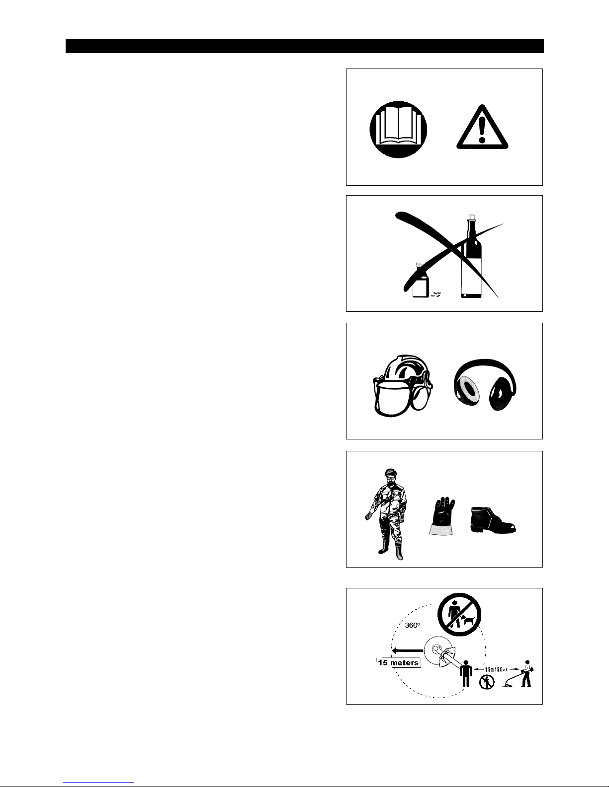
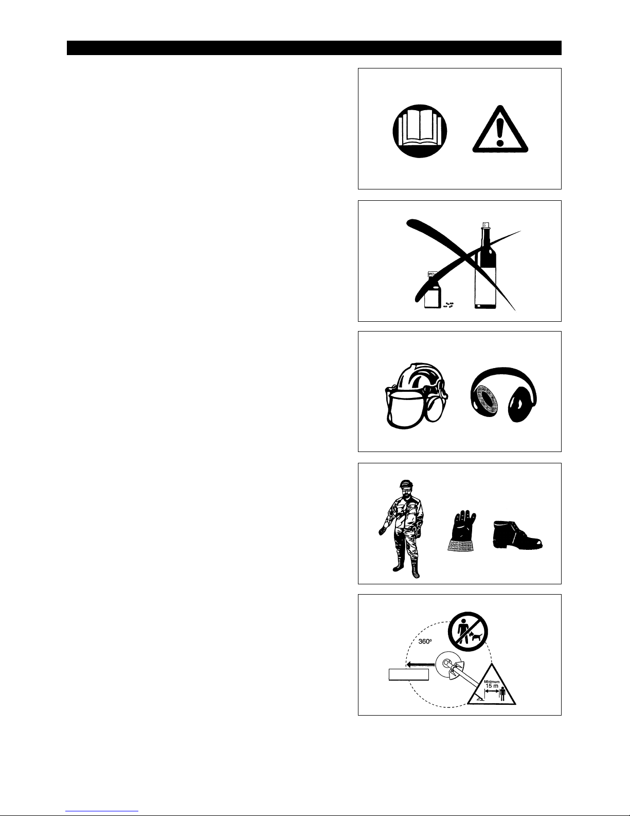
Read instruction Manual
Take Particular care and Attention
Forbidden
No smoking
No open flame
Protective gloves must be worn
Kickback
Keep the area of operation clear of all
persons and pets
Wear sturdy boots with non-slip soles.
Steel toed safety boots are recommended.
Keep distance
Flying object hazard
3
General Instructions
– To ensure correct operation, user has to read this instruction manual to make
himself familiar with the handling of the Petrol Brush Cutter. Users
insufficiently informed will risk danger to themselves as well as others due to
improper handling.
– It is recommended only to lend the Petrol Brush Cutter to people who have
proven to be experienced with Petrol Brush Cutter.
Always hand over the instruction manual.
– First users should ask the dealer for basic instructions to familiarize oneself
with the handling of an engine powered cutter.
– Children and young persons aged under 18 years must not be allowed to
operate the Petrol Brush Cutter. Persons over the age of 16 years may
however use the device for the purpose of being trained only whilst under
supervision of a qualified trainer.
– Use Petrol Brush Cutter with the utmost care and attention.
– Operate the Petrol Brush Cutter only if you are in good physical condition.
Perform all work calmly and carefully. The user has to accept liability for
others.
– Never use the Petrol Brush Cutter after consumption of alcohol or drugs, or if
feeling tired or ill.
Intended use of the machine
– The Petrol Brush Cutter is only intended for cutter grass, weeds, Bushes,
undergrowth it should not be used for any other purpose such as Edging or
hedge cutting as this may cause injury.
Personal protective equipment
– The clothing worn should be functional and appropriate, i.e. it should be
tight-fitting but not cause hindrance. Do not wear either jewelry or clothing
which could become entangled with bushes or shrubs.
– In order to avoid either head-, eye-, hand-or foot injuries as well as to protect
your hearing the following protective equipment and protective clothing must
be used during operation of the Petrol Brush Cutter.
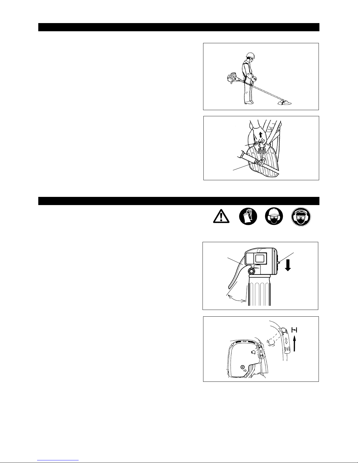
– Always wear a helmet where there is a risk of falling objects. The protective
helmet (1) is to be checked at regular intervals for damage and is to be
replaced at the latest after 5 years. Use only approved protective helmets.
– The visor (2) of the helmet (or alternatively goggles) protects the face from
flying debris and stones. During operation of the Petrol Brush Cutter always
wear goggles, or a visor to prevent eye injuries.
– Wear adequate noise protection equipment to avoid hearing impairment (ear
muffs (3), ear plugs etc.).
– The work overalls (4) protect against flying stones and debris.
We strongly recommend that the user wears work overalls.
– Special gloves (5) made of thick leather are part of the prescribed equipment
and must always be worn during operation of the Petrol Brush Cutter.
– When using the Petrol Brush Cutter, always wear sturdy shoes (6) with a
non-slip sole. This protects against injuries and ensures a good footing.
Starting up the Petrol Brush Cutter
– Please make sure that there are no children or other people within a working
range of 15 meters (50ft), also pay attention to any animals in the working
vicinity.
– Before use always check that the Petrol Brush Cutter is safe for operation:
Check the security of the cutting tool, the control lever for easy action and
check for proper functioning of the control lever lock.
– Rotation of the cutting tool during idling speed is not allowed. Check with
your dealer for adjustment if in doubt. Check for clean and dry handles and
test the function of the start/stop switch.
SAFETY INSTRUCTIONS
(1)
(6)
(2)
(4)
(5)
(3)
Diagrammatic figure

4
Start the Petrol Brush Cutter only in accordance with the instructions.
Do not use any other methods for starting the engine!
– Use the Petrol Brush Cutter and the tools only for such applications as
specified.
– Only start the Petrol Brush Cutter engine, after the entire assembly is done.
Operation of the device is only permitted after all the appropriate accessories
are attached!
– Before starting make sure that the cutting tool has no contact with hard
objects such as branches, stones etc. as the cutting tool will revolve when
starting.
– The engine is to be switched off immediately in case of any engine problems.
– Should the cutting tool hit stones or other hard objects, immediately switch off
the engine and inspect the cutting tool.
– Inspect the cutting tool at short regular intervals for damage (detection of
hairline cracks by means of tapping-noise test).
– Operate the Petrol Brush Cutter only with the shoulder strap attached which is
to be suitably adjusted before putting the Petrol Brush Cutter into operation.
It is essential to adjust the shoulder strap according to the users size to
prevent fatigue occurring during use. Never hold the cutter with one hand
during use.
– During operation always hold the Petrol Brush Cutter with both hands.
Always ensure a safe footing.
– Operate the Petrol Brush Cutter in such a manner as to avoid inhalation of the
exhaust gases. Never run the engine in enclosed rooms (risk of gas
poisoning). Carbon monoxide is an odorless gas.
– Switch off the engine when resting and when leaving the Petrol Brush Cutter
unattended, and place it in a safe location to prevent danger to others or
damage to the machine.
– Never put the hot Petrol Brush Cutter onto dry grass or onto any combustible
materials.
– The cutting tool has to be equipped with it’ s appropriate guard.
Never run the cutter without this guard!
– All protective installations and guards supplied with the machine must be used
during operation.
– Never operate the engine with faulty exhaust muffler.
– Shut off the engine during transport.
– During transport over long distances the tool protection included with the
equipment must always be used.
– Ensure safe position of the Petrol Brush Cutter during car transportation to
avoid fuel leakage.
– When transporting the Petrol Brush Cutter, ensure that the fuel tank is
completely empty.
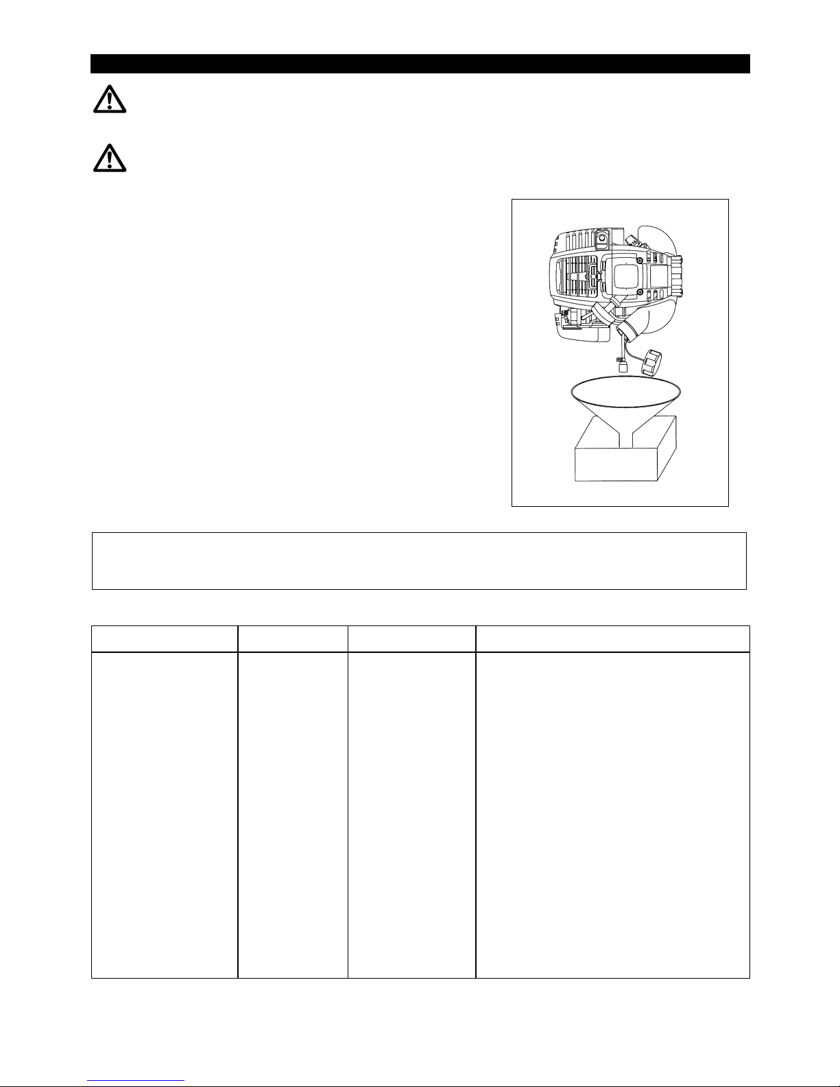
– When unloading the Petrol Brush Cutter from the truck, never drop the Engine
to the ground or this may severely damage the fuel tank.
– Except in case of emergency, never drop or cast the Petrol Brush Cutter to the
ground or this may severely damage the Petrol Brush Cutter.
– Remember to lift the entire equipment from the ground when moving the
equipment. Dragging the fuel tank is highly dangerous and will cause
damage and leakage of fuel, possibly causing fire.
Refuelling
– Shut off the engine during refuelling, keep away from open flames and do not
smoke.
– Avoid skin contact with mineral oil products. Do not inhale fuel vapor.
Always wear protective gloves during refuelling. Change and clean
protective clothing at regular intervals.
– Take care not to spill either fuel or oil in order to prevent soil contamination
(environmental protection). Clean the Petrol Brush Cutter immediately after
fuel has been spilt.
– Avoid any fuel contact with your clothing. Change your clothing instantly if
fuel has been spilt on it (to prevent clothing catching fire).
– Inspect the fuel cap at regular intervals making sure that it can be securely
fastened and does not leak.
– Carefully tighten the fuel tank cap. Change location to start the engine (at
least 3 meters away from the place of refuelling).
– Never refuel in closed rooms. Fuel vapors accumulate at ground lever (risk
of explosions).
– Only transport and store fuel in approved containers. Make sure the fuel
stored is not accessible to children.
䃂㩷
Resting
䃂㩷
Transport
䃂㩷
Refuelling
䃂㩷
Maintenance
䃂㩷
Tool Replacement
3 meters
5
Caution:
Kickback
Diagrammatic
figure
Method of operation
– Only use the Petrol Brush Cutter in good light and visibility. During the winter
season beware of slippery or wet areas, ice and snow (risk of slipping).
Always ensure a safe footing.
– Never cut above waist height.
– Never stand on a ladder and run the Petrol Brush Cutter.
– Never climb up into trees to perform cutting operation with the Petrol Brush
Cutter.
– Never work on unstable surfaces.
– Remove sand, stones, nails etc. found within the working range.
– Foreign particles may damage the cutting tool and can cause dangerous
kick-backs.
– Before commencing cutting, the cutting tool must have reached full working
speed.
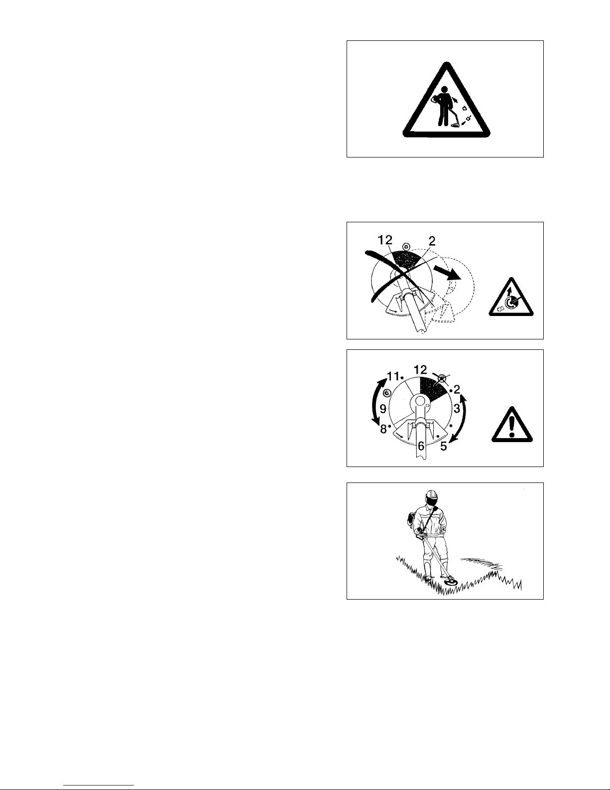
Kickback
– When operating the petrol brush cutter, uncontrolled kickback may occur.
– This is particularly the case when attempting to cut within a blade segment
between 12 and 2 o’clock.
– Never apply the Petrol Brush Cutter within a segment between 12 and 2
o’clock.
– Never apply this segment of the petrol brush cutter blade to solids, such as
bushes and trees, etc., having a diameter in excess of 3 cm or the petrol brush
cutter will be deflected at great force with the risk of injuries.
Kickback prevention
To avoid kickbacks, observe the following:
– Operation within a blade segment between 12 and 2 o’clock presents positive
hazards, especially when using metal cutting tools.
– Cutting operations within a blade segment between 11 and 12 o’clock, and
between 2 and 5 o’clock, must only be performed by trained and experienced
operators, and then only at their own risk.
Easy cutting with almost no kickback is possible within a blade segment
between 8 and 11 o’clock.
Cutting Tools
Employ only the correct cutting tool for the job in hand.
EBH340U/EBH340UG with cutter blade (Star Blade (4 teeth), Eddy Blade (8
teeth)), Nylon cutting head
For cutting thick materials, such as weed, high grass, bushes, shrubs,
underwood, thicket etc. (max. 2 cm dia. thickness). Perform this cutting work
by swinging the petrol brush cutter evenly in half-circles from right to left (similar
to using a scythe).
Maintenance instructions
– The condition of the cutter, in particular of the cutting tool of the protective
devices and also of the shoulder strap must be checked before commencing
work. Particular attention is to be paid to the cutting blades which must be
correctly sharpened.
– Turn off the engine and remove spark plug connector when replacing or
sharpening cutting tools, and also when cleaning the cutter or cutting tool.
Diagrammatic
figure

6
Never straighten or weld damaged cutting tools.
– Operate the Petrol Brush Cutter with as little noise and contamination as
possible. In particular check the correct setting of the carburetor.
– Clean the Petrol Brush Cutter at regular intervals and check that all screws
and nuts are well tightened.
– Never service or store the Petrol Brush Cutter in the vicinity of naked flames.
– Always store the Petrol Brush Cutter in locked rooms and with an emptied fuel
tank.
Observe the relevant accident prevention instructions issued by the relevant trade associations and by the insurance companies.
Do not perform any modifications on the Petrol Brush Cutter as this will endanger your safety.
The performance of maintenance or repair work by the user is limited to those activities as described in the instruction manual. All other work is
to be done by an Authorized Service Agent. Use only genuine spare parts and accessories released and supplied by MAKITA.
Use of non-approved accessories and tools means increased risk of accidents.
MAKITA will not accept any liability for accidents or damage caused by the use of non-approved cutting tools and fixing devices of cutting tools, or
accessories.
First Aid
In case of accident make sure that a first-aid box is available in the vicinity of the
cutting operations. Immediately replace any item taken from the first aid box.
When asking for help, please give the following information:
– Place of accident
– What happened
– Number of injured persons
– Kind of injuries
– Your name
Packaging
The MAKITA Petrol Brush Cutter will be delivered in two protective cardboard
boxes to prevent transport damage. Cardboard is a basic raw material and is
therefore consequently reusable or suitable for recycling (waste paper
recycling).

7
EBH340U/EBH340UG
Model
U handle
Dimensions : length x width x height (without cutting blade) mm
1765 x 615 x 425
Mass (without plastic guard and cutting blade) kg
7.5
Volume (fuel tank) L
0.65
Cutting attachments (cutter blade dia.) mm
255 (Refer to the text P.11)
Engine displacement cm
3
33.5
Maximum engine performance kw
1.07 at 7000 min
-1
Maximum rotational frequency of the spindle min
-1
6850
Engine speed at recommended max. spindle
rotational frequency min
-1
10000
Fuel consumption at max. engine performance kg/h
0.458
Specific fuel consumption at max. engine performance g/kwh
426
Engine speed at idling min
-1
3000
Clutch engagement speed min
-1
4100
Carburetor (Diaphragm - carburetor) type
WALBRO WYL
Ignition system type
Solid state ignition
Spark plug type
NGK CMR6A
Electrode gap mm
0.7 - 0.8
Fuel
Automobile gasoline
Engine oil
SAE 10W-30 oil API Classification
Class SF or higher (4-stroke engine for automobile)
Gear ratio
14/19
EBH340UG:This model has adapted for use with brazillian Gasoline(E25).
TECHNICAL DATA

8
㽾
㾁
㽿
㽽
㽺
㽹
㽵
㽻
㽸
㽴
㾀
㽶
㽼
GB DESIGNATION OF PARTS
1
Fuel Tank
2
Rewind Starter
3 Air Cleaner
4
I-O Switch (on/off)
5 Spark Plug
6
Exhaust Muffler
7
Clutch Case
8 Hanger
9
Handle
10
Throttle Lever
11 Control Cable
12 Shaft
13 Protector
14
Gear Case/Head Case
15 Handle Holder
16 Nylon cutting head
17 Fuel Filler Cap
18 Starter Knob
19
Primmer Pump
20 Choke Lever
21 Exhaust Pipe
22 Oil Gauge
DESIGNATION OF PARTS
㽴
㾅
㽳
㽲
㽷
㪉㪈
㾄
㪉㪉
EBH340U/EBH340UG
Petrol Brush Cutter
㾃
㾂
9
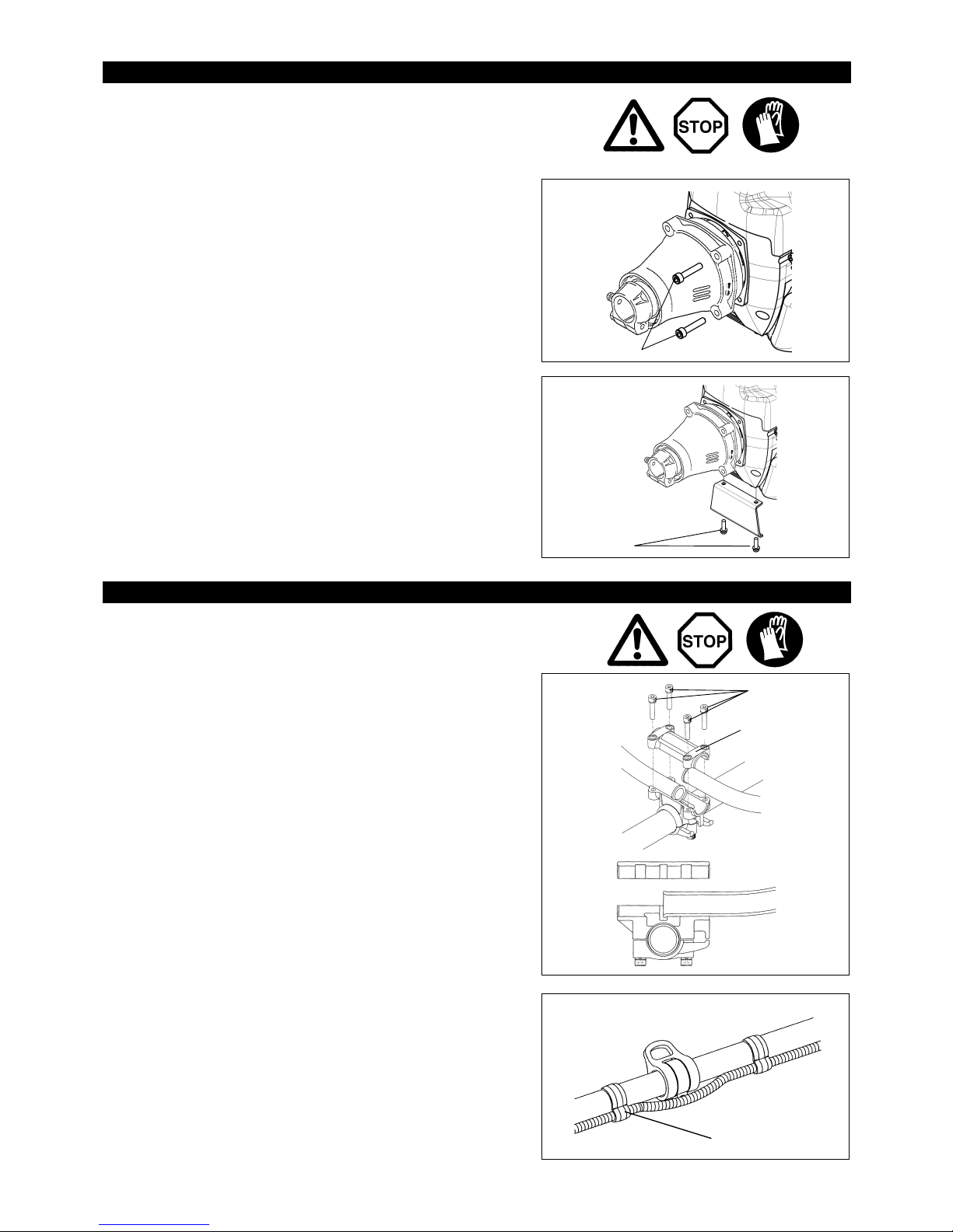
CAUTION: Before doing any work on the petrol brush cutter, always switch off
the motor and pull the spark plug connector off the spark plug.
Always wear protective gloves!
CAUTION: Start the Petrol Brush Cutter only after having assembled it
completely.
– After checking the parts, fasten the drive shaft to the engine with four bolts M6
x 30 (1).
– Mount the stand by two screws M5 x 12 (2).
MOUNTING OF HANDLE For BH3600
– Place the handle with the throttle lever on the handle holder on the right side
(to be held by the right hand) and the other on the left side.
– Fit the handle edge to the handle holder groove, and provisionally fix the
upper side (3) of the handle holder by four bolts M5 x 25 (4).
– Adjust the handle to an angle easy to manipulate, and tighten the bolt (4)
uniformly on the right and left sides.
– Fix the control cable to the shaft by two clips (5).
ASSEMBLY OF ENGINE AND SHAFT
MOUNTING OF HANDLE
Clips (5)
(4)
(3)
(1)
(2)
10
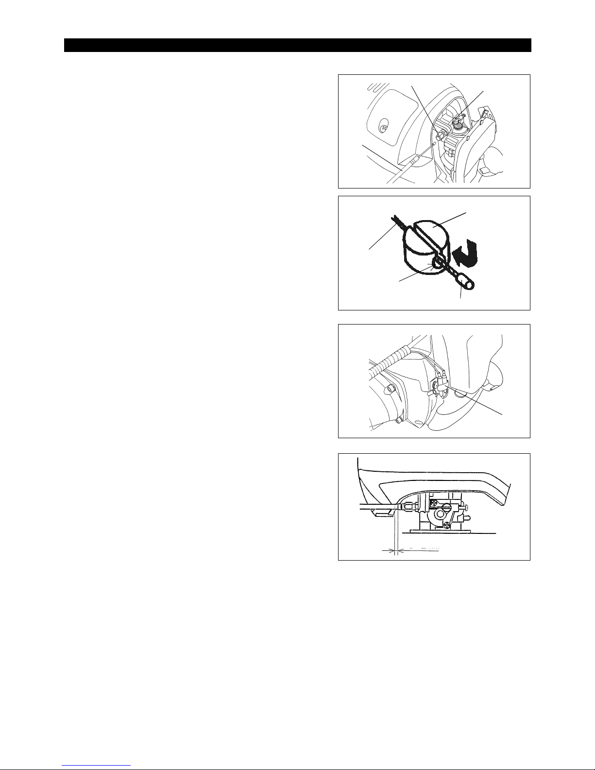
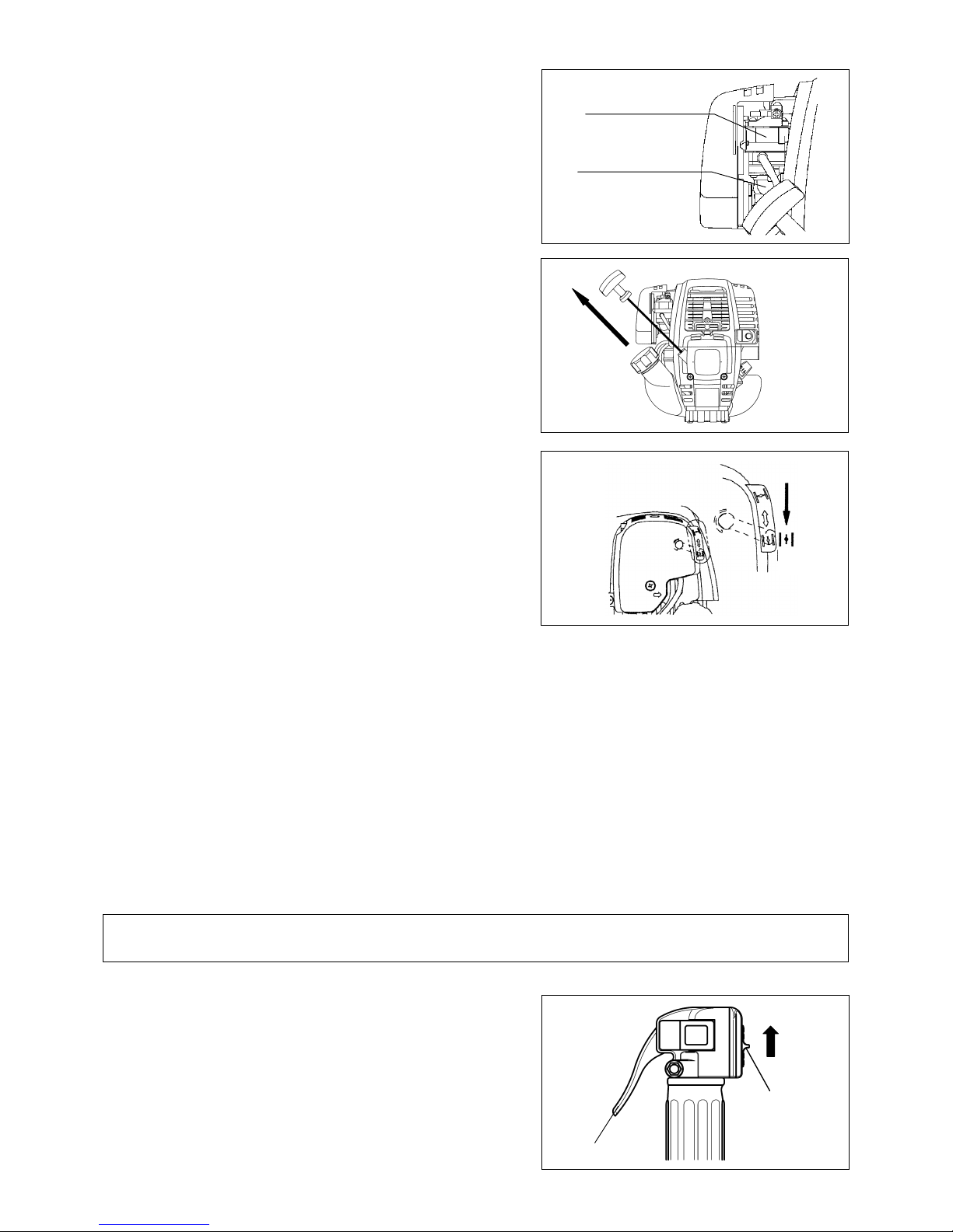
– Remove the air cleaner cover.
– Place the control cable (1) in the adjusting bolt (2), and shift the swivel (3) so
that the cable will be put in the swivel groove. At this time, the round-hole
side of the swivel will be oriented toward the inner wire end-metal fitting.
– Release the swivel, and confirm that the inner wire-end metal fitting will be
placed in the hole.
– Mount the air cleaner cover.
CONNECTION OF SWITCH CORD
– Connect the switch cords to the two cords from the engine by inserting one
into the other.
– Fix the cord connector by clamp (4).
ADJUSTMENT OF CONTROL CABLE
Adjust the control cable by adjusting bolt so that it will have 1 to 2 mm play when
the throttle lever is set to the low-speed position by carburetor adjusting bolt. (Be
careful that the cutter blade will not turn in idling.)
MOUNTING OF CONTROL CABLE
Control cable
Swivel
End fitting
Round-hole
(4)
Insert
1-2 mm
(2)
(1)
(3)
11
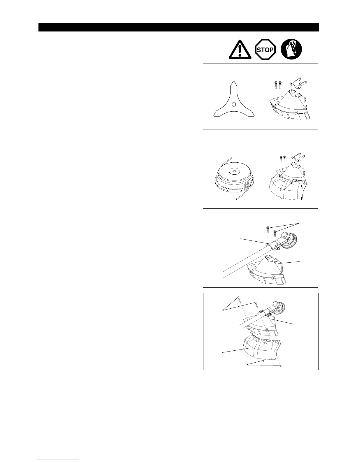
To meet the applicable safety provisions, only the tool/protector combinations as
indicated in the table must be used.
Be sure to use genuine MAKITA cutter blades or nylon cutting head.
– The cutter blade must be well polished, free of cracks or breakage. If the
cutter blade hits against a stone during operation, stop the engine and check
the blade immediately.
– Polish or replace the cutter blade every three hours of operation.
– If the nylon cutting head hits against a stone during operation, stop the engine
and check the nylon cutting head immediately.
CAUTION: The appropriate protector must always be installed, for your own
safety and in order to comply with accident-prevention regulations.
Operation of the equipment without the guard being in place is not
permitted.
– The outside diameter of the cutter blade must be 255mm (10”). Never use
any blades surpassing 255mm (10”) in outside diameter.
– Fix the protector (1) to the clamp (3) with two bolts M6 x 30 (2).
NOTE: Tighten the right and left bolts evenly so that the gap between the clamp
(3) and the protector (1) will be constant.
Otherwise, the protector sometimes may not function as specified.
– In use of the nylon cutting head insert the protector (6) into the protector (1),
and fasten them with two screw (4) and two nuts (5).
Cutter Blade Protector for metal blades
MOUNTING OF PROTECTOR
(2)
(3)
(1)
(4)
(1)
(5)
(6)
Nylon cutting head Protector for cord cutter
12
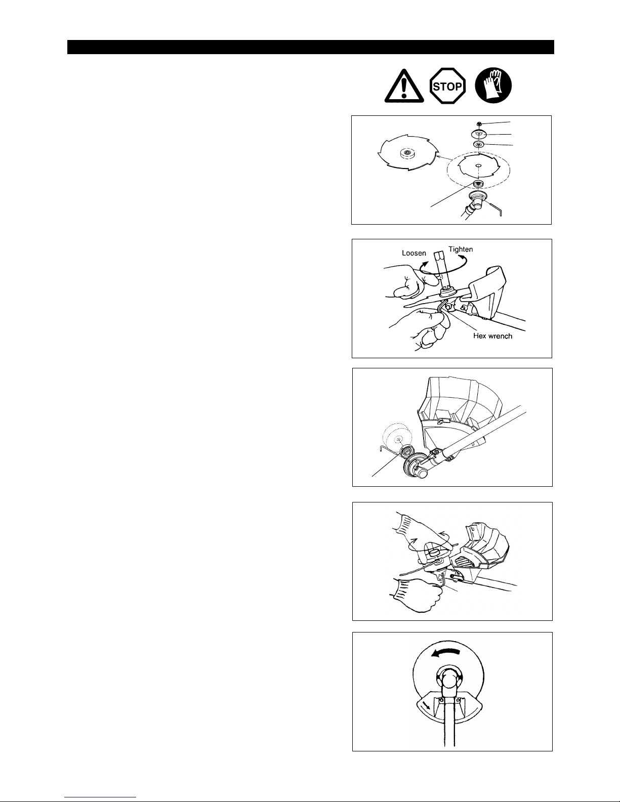
Turn the machine upside down, and you can replace the cutter blade or the
nylon cutting head easily.
– Insert the hex wrench through the hole in the gear case and rotate the receiver
washer (4) until it is locked with the hex wrench.
– Loosen the nut (1) (left-hand thread) with the socket wrench and remove the
nut (1), cup (2), and clamp washer (3).
Mounting of cutter blade
With the hex wrench still in place.
– Mount the cutter blade onto the shaft so that the guide of the receiver washer
(4) fits in the arbor hole in the cutter blade. Install the clamp washer (3), cup
(2), and secure the cutter blade with the nut (1).
[Tightening torque: 13 - 23 Nm]
NOTE: Always wear gloves when handling the cutter blade.
NOTE: The cutter blade-fastening nut (with coned disc spring) is a consumable
part.
If there appears any wear or deformation on the coned disc spring,
replace the nut.
Mounting of nylon cutting head
– The clamp washer (3), cup (2), and nut (1) are not necessary for mounting the
nylon cutting head. The nylon head should go on top of the receiver washer
(4).
– Insert the hex wrench through the hole in the gear case and rotate the receiver
washer (4) until it is locked with the hex wrench.
– Then screw the nylon cutting head onto the shaft by turning it
counter-clockwise.
– Remove the hex wrench.
– Make sure that the blade is the left way up.
MOUNTING OF CUTTER BLADE OR NYLON CUTTING HEAD
Rotation
Tighten
Hex wrench
Loosen
(4)
(2)
(1)
(4)
(3)
13
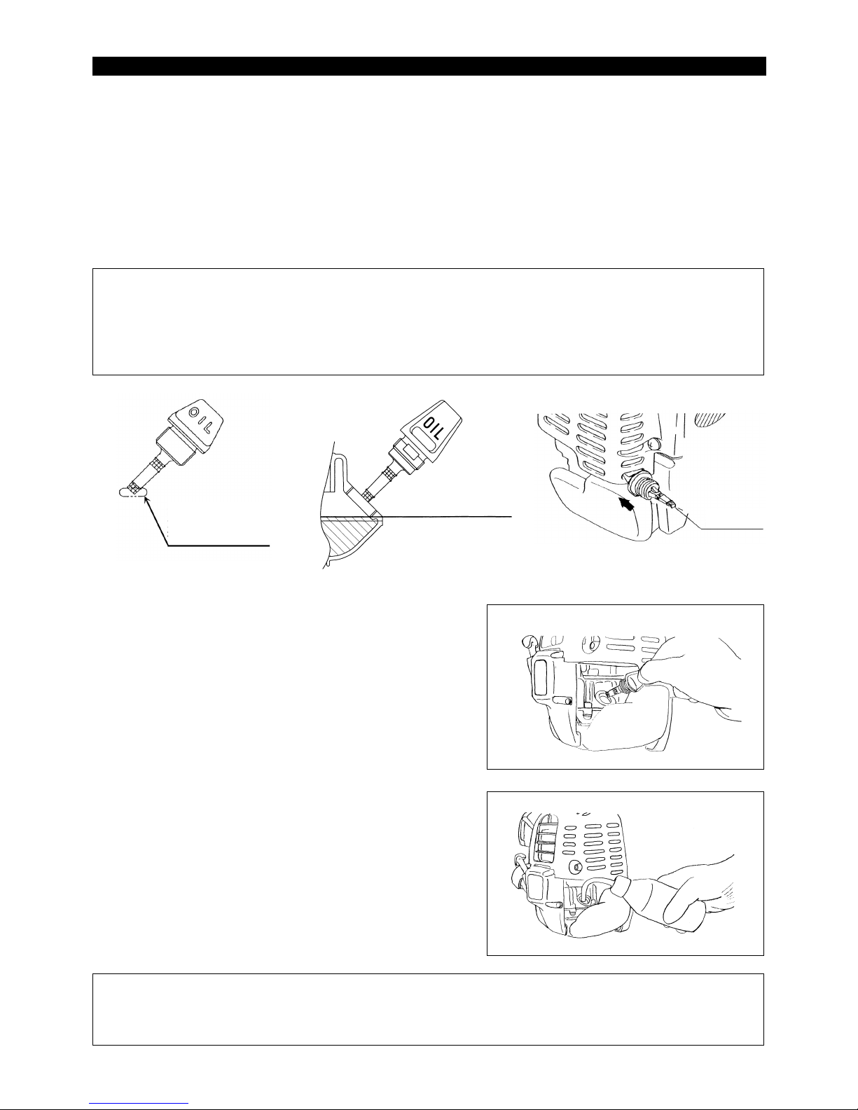
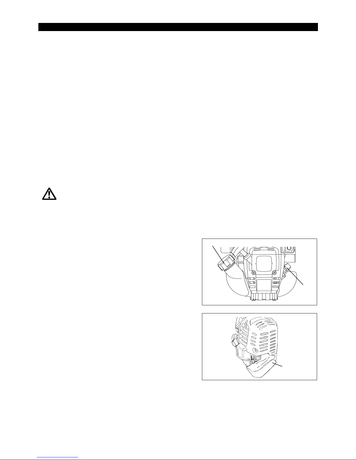
Inspection and Refill of Engine Oil
– Perform the following procedure, with the engine cooled down.
– While keeping the engine level, remove the oil gauge, and confirm that the oil is filled within the upper and lower limit marks.
When the oil is in short in such a way that the oil gauge touches the oil only by its tip, in particular with the oil gauge remaining inserted in the
crankcase without screwing-in (Fig. 1), refill new oil near the port (Fig. 2).
– For reference, the oil refill time is about 15 h (refill frequency: 15 times).
– If the oil changes in color or mixes with dirt, replace it with new one. (For the interval and method of replacement, refer to P. 18)
Recommended oil: SAE 10W-30 oil of API Classification, Class SF or higher (4-stroke engine for automobile)
Oil volume: Approx. 0.1 L
Note: If the engine is not kept upright, oil may go into around the engine, and may be refilled excessively.
If the oil is filled above the limit, the oil may be contaminated or may catch fire with white.
Point 1 in Replacement of Oil : “Oil Gauge”
– Remove dust or dirt near the oil refill port, and detach the oil gauge.
– Keep the detached oil gauge free of sand or dust. Otherwise, any sand or dust adhering to the oil gauge may cause irregular oil circulation
or wear on the engine parts, which will result in troubles.
– As an example to keep the oil gauge clean, it is recommended to insert the oil gauge on its knob side into the engine cover, as shown in
Fig.3.
(1) Keep the engine level, and detach the oil gauge.
(2) Fill oil up to the edge of the oil refill port. (Refer to Fig.2).
Feed oil with the lubricant refill container.
(3) Securely tighten the oil gauge. Insufficient tightening may cause oil leakage.
Point 2 in Replacement of Oil: “If oil spills out”
– If oil spills out between the fuel tank and engine main unit, the oil is sucked into through the cooling air intake port, which will contaminate
the engine. Be sure to wipe out spilt oil before start of operation.
BEFORE START OF OPERATION
Oil gauge
If oil adheres around
this tip, refill new oil.
Upper limit of oil level
(Lower part of oil refill port
threaded part)
Fig.1 Fig.2 Fig.3
14
REFUELING
Handling of Fuel
It is necessary to handle fuel with utmost care. Fuel may contain substances similar to solvents. Refueling must be performed in a sufficiently
ventilated room or in the open air. Never inhale fuel vapor, and keep fuel away from you. If you touch fuel repeatedly or for a long time, the skin
becomes dry, which may cause skin disease or allergy. If fuel enters into the eye, clean the eye with fresh water. If your eye remains still irritated,
consult your doctor.
Storage Period of Fuel
Fuel should be used up within a period of 4 weeks, even if it is kept in a special container in a well-ventilated shade.
If a special container is not used or if the container is not covered, fuel may deteriorate in one day.
STORAGE OF MACHINE AND REFILL TANK
– Keep the machine and tank at a cool place free from direct sunshine.
– Never keep the fuel in the cabin or trunk.
Fuel
The engine is a four-stroke engine. Be sure to use an automobile gasoline (regular gasoline or premium gasoline).
Points for Fuel
– Never use a gasoline mixture which contains engine oil. Otherwise, it will cause excessive carbon accumulation or mechanical troubles.
– Use of deteriorated oil will cause irregular startup.
– EBH340UG :This model has adapted for use with brazillian Gasoline(E25).
Refueling
WARNING: INFLAMMABLES STRICTLY PROHIBITED
Gasoline used: Automobile gasoline (unleaded gasoline)
– Loosen the tank cap a little so that there will be no difference in atmospheric
pressure.
– Detach the tank cap, and refuel, discharging air by tilting the fuel tank so that
the refuel port will be oriented upward. (Never refill fuel full to the oil refill port.)
– Wipe well the periphery of the tank cap to prevent foreign matter from entering
into the fuel tank.
– After refueling, securely tighten the tank cap.
٨
If there is any flaw or damage on the tank cap, replace it.
٨
The tank cap is consumable, and therefore should be renewed every two to
three years.
Fuel upper limit
Fuel tank
Fuel tank ca
p
15
Attachment of shoulder strap
– Adjust the strap length so that the cutter blade will be kept parallel with the
ground.
Detachment
– In case of emergency, remove the emergency detachment lever (1) by pulling
strongly with a finger. The machine sill detach from body.
Be extremely careful to maintain control of the machine at this time. Do not
allow the machine to be deflected toward you or anyone in the work vicinity.
WARNING: Failure to maintain complete control of the machine at all could
result in serious bodily injury or DEATH.
Observe the applicable accident prevention regulations!
STARTING
Move at least 3m away from the place of refuelling. Place the Petrol Brush Cutter on a clean piece of ground taking care that the cutting tool
does not come into contact with the ground or any other objects.
A:Cold start
1) Set this machine on a flat space.
For machine with U Handle
1) Set the I-O switch (1) to OPERATION.
2) Choke lever
Close the choke lever.
Choke opening:
– Full closing in cold or when the engine is cold.
– Full or half opening in restart just after stop of operation.
CORRECT HANDLING OF MACHINE
POINTS IN OPERATION AND HOW TO STOP
CLOSE
I-O switch (1)
Throttle lever
Low speed
High speed
OPERATION
Hanger
(1)
16
3) Primer pump
Continue to push the primer pump until fuel enters into the primer pump. (In
general, fuel enters into the primer pump by 7 to 10 pushes.)
If the primer pump is pushed excessively, an excess of gasoline returns to the
fuel tank.
4) Recoil starter
– Pull the start knob gently until it is hard to pull (compression point). Then,
return the start knob, and pull it strongly.
– Never pull the rope to the full. Once the start knob is pulled, never release
your hand immediately. Hold the start knob until it returns to its original
point.
5) Choke lever
When the engine starts, open the choke lever.
– Open the choke lever progressively while checking the engine operation.
Be sure to open the choke lever to the full in the end.
– In cold or when the engine is cooled down, never open the choke lever
suddenly. Otherwise, the engine may stop.
6) Warm-up operation
Continue warm-up operation for 2 to 3 minutes.
Note: − If the starter handle is pulled repeatedly when the choke lever remains at “START” position, the engine will not start easily due to
excessive fuel intake.
− In case of excessive fuel intake, remove the spark plug and pull the starter handle slowly to remove excess fuel. Also, dry the electrode
section of the spark plug.
Caution during operation:
If the throttle lever is opened fully in a no-load operation, the engine rotation is increased to 10,000 min-1 or more. Never operate the engine at a
higher speed than required and at an approximate speed of 6,000 - 8,500 min
-1
.
B: Startup after warm-up operation
1) Push the primer pump repeatedly.
2) Keep the throttle lever at the idling position.
3䋩 Pull the recoil starter strongly.
4) If it is difficult to start the engine, open the throttle by about 1/3.
Pay attention to the cutter blade which may rotate.
Attention in Operation
When the engine is operated upside down, white smoke may come out from the muffler.
STOPPING
1) Release the throttle lever (2) fully, and when the engine rpm has lowered, set
the I-O switch to STOP the engine will now stop.
2) Be aware that the cutting head may not stop immediately and allow it to slow
down fully.
OPEN
STOP
Throttle lever (2)
I-O switch
㩷
(1)
Carburettor
Primer Pump

17
Most effective cutting area
Operation of Throttle Lever
With the throttle lever main unit held by hand (with the lock-off lever pushed), pull the throttle lever and the engine rotation will be increased.
Release the throttle lever, and the engine will run idle again.
Release the hand from the throttle lever main unit, and the lock-off lever will return automatically so that the throttle lever will not be pulled by
mistake.
Adjustment of Engine ROTATION
When adjusting the engine rotation with the throttle lever opened to the full, turn the throttle control dial. Turn the dial clockwise, and the engine
rotation will be reduced. Turn the dial counterclockwise, and the engine rotation will be increased.
ADJUSTMENT OF LOW-SPEED ROTATION (IDLING)
When it is necessary to adjust the low-speed rotation (idling), perform it by the carburetor adjusting screw.
CHECKUP OF LOW-SPEED ROTATION
– Set the low-speed rotation to 3000min
-1
.
If it is necessary to change the rotation speed, regulate the adjusting screw
(illustrated on the left), with Phillips screwdriver.
– Turn the adjusting screw to the right, and the engine rotation will increase.
Turn the adjusting screw to the left, and the engine rotation will drop.
– The carburetor is generally adjusted before shipment. If it is necessary to
readjust it, please contact Authorized Service Agent.
CAUTION: The cutting tools mentioned below must only be resharpened by an
authorized facility. Manual resharpening will result in imbalances of
the cutting tool causing vibrations and damage to the equipment.
– cutter blade (star blade (4 teeth), eddy blade (8 teeth))
An expert resharpening and balancing service is provided by Authorized
Service Agents.
NOTE: To increase the service life of the cutter blade (star blade, eddy blade) it
may be turned over once, until both cutting edges have become blunt.
NYLON CUTTING HEAD
The nylon cutting head is a dual string trimmer head capable of both automatic
and bump & feed mechanisms.
The nylon cutting head will automatically feed out the proper length of nylon cord
by the changes in centrifugal force caused by increasing or decreasing rpms.
However, to cut soft grass more efficiently, bump the nylon cutting head against
the ground to feed out extra cord as indicated under operation section.
Operation
– Increase the nylon cutting head speed to approx. 6,000min-1.
Low speed (under 4,800min
-1
) is not suitable, the nylon cord will not feed out
properly at low speed.
– The most effective cutting area is shown by the shaded area.
If the nylon cord does not feed out automatically proceed as follows:
1. Release the throttle lever to run the engine idle and then squeeze the throttle
lever fully. Repeat this procedure until the nylon cord feeds out to the proper
length.
2. If the nylon cord is too short to feed out automatically with the above
procedure, bump the knob of the nylon cutting head against the ground to
feed out the nylon cord.
3. If the nylon cord does not feed out with procedure 2, rewind/replace the nylon
cord by following the procedures described under “Replacing the nylon cord”
RESHARPENING THE CUTTING TOOL
A
djusting screw
Carburetor
Idle speed Full speed
Tap knob
18
CAUTION: Before doing any work on the petrol brush cutter, always stop the engine and pull the plug cap off the spark plug (see “checking the
spark plug”).
Always wear protective gloves!
To ensure a long service life and to avoid any damage to the equipment, the following servicing operations should be performed at regular
intervals.
Daily checkup and maintenance
– Before operation, check the machine for loose screws or missing parts. Pay particular attention to the tightness of the cutter blade or nylon
cutting head.
– Before operation, always check for clogging of the cooling air passage and the cylinder fins.
Clean them if necessary.
– Perform the following work daily after use:
• Clean the petrol brush cutter externally and inspect for damage.
• Clean the air filter. When working under extremely dusty conditions, clean the filter the several times a day.
• Check the blade or the nylon cutting head for damage and make sure it is firmly mounted.
• Check that there is sufficient difference between idling and engagement speed to ensure that the cutting tool is at a standstill while the engine
is idling (if necessary reduce idling speed).
If under idling conditions the tool should still continue to run, consult your nearest Authorized Service Agent.
– Check the functioning of the I-O switch, the lock-off lever, the throttle lever.
REPLACEMENT OF ENGINE OIL
Deteriorated engine oil will shorten the life of the sliding and rotating parts to a great extent. Be sure to check the period and quantity of
replacement.
ATTENTION: In general, the engine main unit and engine oil still remain hot just after the engine is stopped. In replacement of oil,
confirm that the engine main unit and engine oil are sufficiently cooled down. Otherwise, there may remain a risk of
scald.
Note: If the oil filled above the limit, it may be contaminated or may catch fire with white smoke.
Interval of replacement: Initially, every 20 operating hours, and subsequently every 50 operating hours
Recommended oil: SAE10W-30 oil of API Classification SF Class or higher (4-stroke engine oil for automobile)
In replacement, perform the following procedure.
1) Confirm that the tank cap is tightened securely.
2) Detach the oil gauge.
Keep the oil gauge free from dust or dirt.
3) Place waste or paper near the oil refill port.
SERVICING INSTRUCTIONS
Fuel tank cap
Oil gauge
Waste or paper
㪧㫉㫆㫋㫉㫌㫊㫀㫆㫅
㪧㫉㫆㫋㫉㫌㫊㫀㫆㫅㪧㫉㫆㫋㫉㫌㫊㫀㫆㫅
㪧㫉㫆㫋㫉㫌㫊㫀㫆㫅
19
4) Detach the oil gauge, and drain oil, tilting the main unit toward the oil refill port.
Drain oil in a container.
5) Keep the engine level, and feed new oil up to the edge of the oil refill port.
In refill, use a lubricant refill container.
6) After refill, securely tighten the oil gauge. Insufficient tightening of the oil
gauge will lead to oil leakage.
POINTS ON OIL
– Never discard replaced engine oil in garbage, earth or sewage ditch. Disposal of oil is regulated by law. In disposal, always follow the
relevant laws and regulations. For any points remaining unknown, contact Authorized Service Agent.
– Oil will deteriorate even when it is kept unused. Perform inspection and replacement at regular intervals (replace with new oil every 6
months).
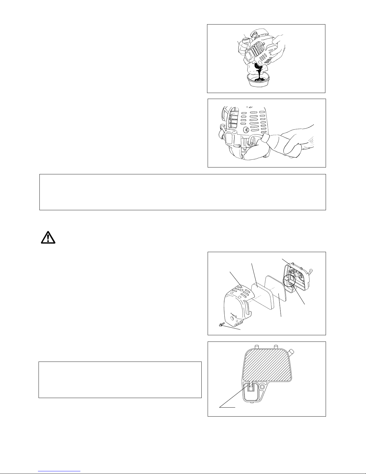
CLEANING OF AIR CLEANER
DANGER: INFLAMMABLES STRICTLY PROHIBITED
Interval of Cleaning and Inspection: Daily (every 10 operating hours)
– Turn the choke lever to the full close side, and keep the carburetor off from
dust or dirt.
– Remove the air cleaner cover-fixing bolts.
– Pull the cover lower side and detach the air cleaner cover.
– If oil adheres to the element (sponge), squeeze it firmly.
– For heavy contamination:
1) Remove the element (sponge), immerse it in warm water or in water-diluted
neutral detergent, and dry it completely.
2) Clean the element (felt) with gasoline, and dry it completely.
– Before attaching the element, be sure to dry it completely. Insufficient drying
of the element may lead to difficult startup.
– Wipe out with waste cloth, oil adhering around the air cleaner cover and plate
breather.
– Immediately after cleaning is finished, attach the cleaner cover and tighten it
with fixing bolts. (In remounting, first place the upper claw, and then the lower
claw.)
Points in Handling Air Cleaner Element
– Clean the element several times a day, if excessive dust adheres to it.
– If operation continues with the element remaining not cleared of oil, oil in
the air cleaner may fall outside, resulting in oil contamination.
Plate
Breather Part
Fixing bolt
Air cleaner cover
Element (sponge)
Element (felt)
Pick this part and remove the element (felt).

20
0.7mm-0.8mm
(0.028”-0.032”)
CHECKING THE SPARK PLUG
– Only use the supplied universal wrench to remove or to install the spark plug.
– The gap between the two electrodes of the spark plug should be 0.7-0.8mm
(0.028”-0.032”). If the gap is too wide or too narrow, adjust it. If the spark
plug is clogged with carton or fouled, clean it thoroughly or replace it.
CAUTION: Never touch the spark plug connector while the engine is running
(danger of high voltage electric shock).
SUPPLY OF GREASE TO GEAR CASE
– Supply grease (Shell Alvania 2 or equivalent) to the gear case through the
grease hole every 30 hours. (Genuine MAKITA grease may be purchased
from your MAKITA dealer.)
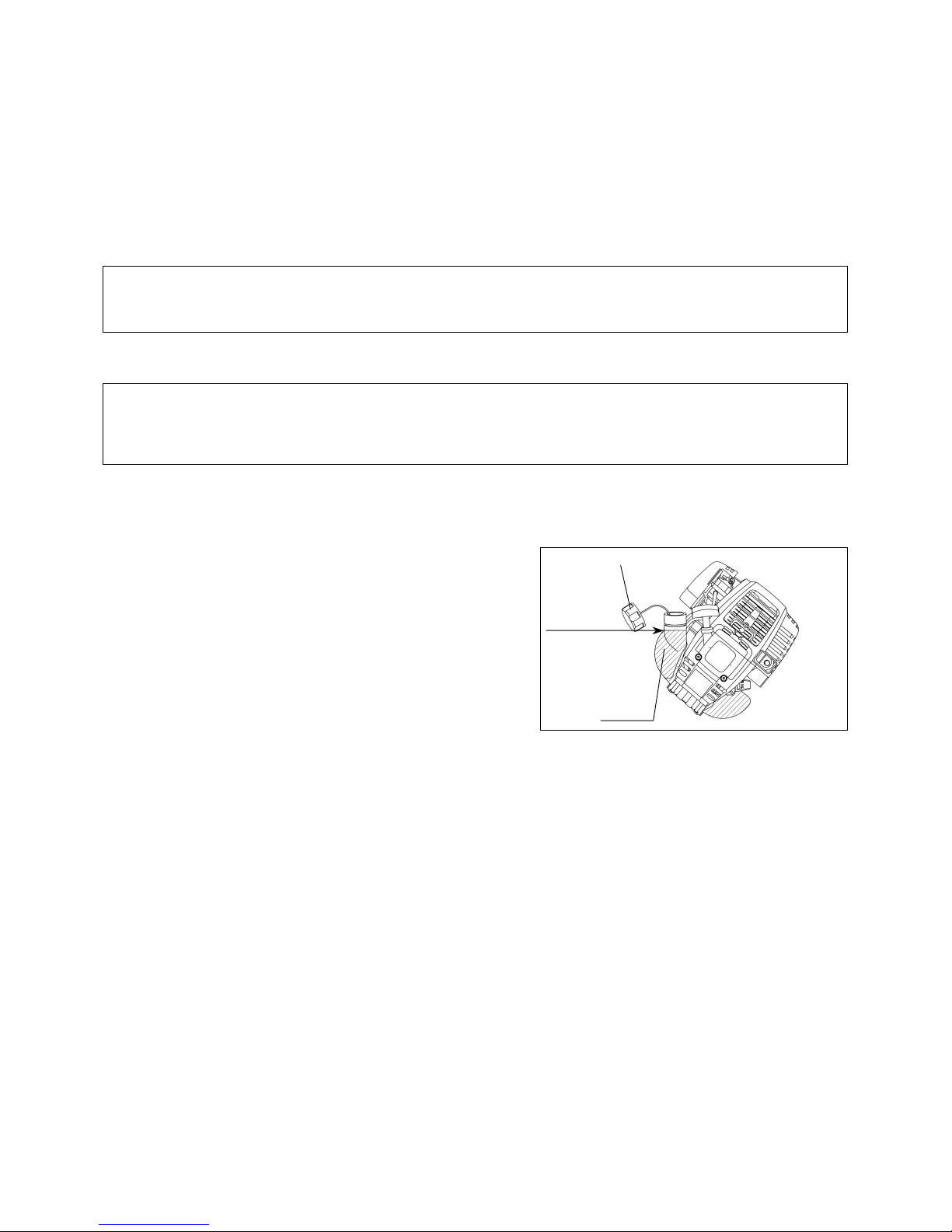
CLEANING OF FUEL FILTER
WARNING: INFLAMMABLES
STRICTLY
PROHIBITED
Interval of Cleaning and Inspection: Monthly (every 50 operating hours)
Suction head in the fuel tank
– The fuel filler (1) of the suction head is used to filler the fuel required by the
carburetor.
– A periodical visual inspection of the fuel filter is to be conducted. For that
purpose open the tank cap, use a wire hook and pull out the suction head
through the tank opening. Filters found to have hardened, been polluted or
clogged up are to be replaced.
– Insufficient fuel supply can result in the admissible maximum speed being
exceeded. It is therefore important to replace the fuel filter at least quarterly
to ensure satisfactory fuel supply to the carburetor.
REPLACEMENT OF FUEL PIPE
CAUTION: INFLAMMABLES STRICTLY PROHIBITED
Interval of Cleaning and Inspection: Daily (every 10 operating hours)
Replacement: Annually (every 200 operating hours)
Replace the fuel pipe every year, regardless of operating frequency. Fuel
leakage may lead to fire.
If any leakage is detected during inspection, replace the oil pipe immediately.
INSPECTION OF BOLTS, NUTS AND SCREWS
– Retighten loose bolts, nuts, etc.
– Check for fuel and oil leakage.
– Replace damaged parts with new ones for safety operation.
CLEANING OF PARTS
– Keep the engine always clean.
– Keep the cylinder fins free of dust or dirt. Dust or dirt adhering to the fins will cause seizure.
REPLACEMENT OF GASKETS AND PACKINGS
In reassembling after the engine is dismounted, be sure to replace the gaskets and packings with new ones.
Any maintenance of adjustment work that is not included and described in this manual is only to be performed by Authorized Service Agents.
Gear case
Grease hole
Fuel pipe
Hose clam
p
Fuel pipe
21
WARNING: When draining the fuel, be sure to stop the engine and confirm that the engine cools
down.
Just after stopping the engine, it may still hot with possibility of burns, inflammability and fire.
ATTENTION: When the machine is kept out of operation for a long time, drain up all fuel from the fuel
tank and carburetor, and keep it at a dry and clean place.
– Drain up fuel from the fuel tank and carburetor according to the following
procedure:
1) Remove the fuel tank cap, and drain fuel completely.
If there is any foreign matter remaining in the fuel tank, remove it
completely.
2) Pull out the fuel filter from the refill port using a wire.
3) Push the primer pump until fuel is drained from there, and drain fuel
coming into the fuel tank.
4) Reset the filter to the fuel tank, and securely tighten the fuel tank cap.
5) Then, continue to operate the engine until it stops.
– Remove the spark plug, and drip several drops of engine oil through the spark
plug hole.
– Gently pull the starter handle so that engine oil will spread over the engine,
and attach the spark plug.
– Attach the cover to the cutter blade.
– During storage, keep the rod horizontal or keep the machine upright with the
blade edge oriented upward. (In this case, pay full attention to prevent the
machine from falling.)
Never store the machine with the cutter blade edge oriented downward.
Lubricating oil may spill out.
– Keep the drained fuel in a special container in a well-ventilated shade.
Attention after long-time storage
– Before startup after long-time shutdown, be sure to replace oil (refer to P 18). Oil will deteriorate while the machine is kept out of
operation.
Fault location
Fault System Observation Cause
Engine not starting or with
difficulty
Ignition system Ignition spark O.K.
Fault in fuel supply or compression system, mechanical
defect
No ignition spark
STOP-switch operated, wiring fault or short circuit, spark
plug or connector defective, ignition module faulty
Fuel supply Fuel tank filled
Incorrect choke position, carburetor defective, fuel supply
line bent or blocked, fuel dirty.
Compression
No compression when
pulled over
Cylinder bottom gasket defective, crankshaft seals
damaged, cylinder or piston rings defective or improper
sealing of spark plug
Mechanical fault Starter not engaging Broken starter spring, broken parts inside of the engine
Warm start problems
Tank filled ignition spark
existing
Carburetor contaminated, have it cleaned
Engine starts but dies Fuel supply Tank filled Incorrect idling adjustment, carburetor contaminated
Fuel tank vent defective, fuel supply line interrupted,
cable or STOP-switch faulty
Insufficient performance
Several systems
may simultaneously
be affected
Engine idling poor
Air filter contaminated, carburetor contaminated, muffler
clogged, exhaust duct in the cylinder clogged
STORAGE

22
Operating time
Item
Before
operation
After
lubrication
Daily
(10h)
30h 50h 200h
Shutdown
/rest
Corres-
ponding P
Inspect/clean 䂾 13
Engine oil
Replace 䂾
*1
18
Tightening parts
(bolt, nut)
Inspect 䂾 20
Clean/inspect 䂾 㵪
Fuel tank
Drain fuel 䂾
*3
21
Throttle lever Check function 䂾 15
Stop switch Check function 䂾 15
Cutting blade Inspect 䂾 䂾 11
Low-speed rotation Inspect/adjust 䂾 17
Air cleaner Clean 䂾 19
Ignition plug Inspect 䂾 20
Cooling air duct Clean/inspect 䂾 20
Inspect 䂾 20
Fuel pipe
Replace
䃁
*2
㵪
Gear-case grease Refill 䂾
20
Fuel filter Clean/replace 䂾
20
Clearance between air intake
valve and air discharge valve
Adjust
䃁
*2
㵪
Oil tube Inspect
䃁
*2
Engine overhaul
䃁
*2
㵪
Carburetor Drain fuel 䂾*3 21
*1 Perform initial replacement after 20h operation.
*2 For the 200 operating hour inspection, request Authorized Service Agent or a machine shop.
*3 After emptying the fuel tank, continue to run the engine and drain fuel in the carburetor.

23
TROUBLESHOOTING
Before making a request for repairs, check a trouble for yourself. If any abnormality is found, control your machine according to the description of
this manual. Never tamper or dismount any part contrary to the description. For repairs, contact Authorized Service Agent or local dealership.
State of abnormality Probable cause (malfunction) Remedy
Failure to operate primer pump Push 7 to 10 times.
Low pulling speed of starter rope Pull strongly.
Lack of fuel Feed fuel.
Clogged fuel filter Clean
Broken fuel tube Straighten fuel tube
Deteriorated fuel
Deteriorated fuel makes starting more difficult.
Replace with new one. (Recommended
replacement: 1 month)
Excessive suction of fuel
Set throttle lever from medium speed to high
speed, and pull starter handle until engine
starts. Once engine starts, cutter blade
starts rotating. Pay full attention to cutter
blade.
If engine will not start still, remove spark plug,
make electrode dry, and reassemble them as
they originally are. Then, start as specified.
Detached plug cap Attach securely
Contaminated spark plug Clean
Abnormal clearance of spark plug Adjust clearance
Other abnormality of spark plug Replace
Abnormal carburetor Make request for inspection and maintenance.
Starter rope cannot be pulled Make request for inspection and maintenance
Engine does not start
Abnormal drive system Make request for inspection and maintenance
Insufficient warm-up Perform warm-up operation
Choke lever is set to “CLOSE” although engine
is warmed up
Set to “OPEN”
Clogged fuel filter Clean
Contaminated or clogged air cleaner Clean
Abnormal carburetor Make request for inspection and maintenance
Engine stops soon
Engine speed does not increase
Abnormal drive system Make request for inspection and maintenance
Loosened cutter blade-tightening nut Tighten securely
Twigs caught by cutter blade or
dispersion-preventing cover
Remove foreign matter
Cutter blade does not rotate
Abnormal drive system Make request for inspection and maintenance.
Broken, bent or worn cutter blade Replace cutter blade
Loosened cutter blade-tightening nut Tighten securely
Shifted convex part of cutter blade and cutter
blade support fitting
Attach securely
Main unit vibrates abnormally.
Abnormal drive system Make request for inspection and maintenance
High idling rotation Adjust
Detached throttle wire Attach securely
Cutter blade does not stop immediately.
Abnormal drive system Make request for inspection and maintenance
Detached connector Attach securely
Abnormal electric system Make request for inspection and maintenance.
Engine does not stop.
When the engine does not start after warm-up operation:
If there is no abnormality found for the check items, open the throttle by about 1/3 and start the engine.
Stop engine immediately
Stop engine immediately
Stop engine immediately
Run engine at idling, and set choke
lever to CLOSE.

24
Nous vous remercions d'avoir fait l'acquisition de la débroussailleuse
MAKITA. Nous sommes heureux de pouvoir vous conseiller la
débroussailleuse MAKITA qui représente le résultat d'un long programme
de développement et de plusieurs années de recherche et d'expérience.
Veuillez lire cette brochure qui fait référence en détail aux différents points
témoignant de l'efficacité exceptionnelle de votre débroussaileuse MAKITA.
Table des matières Page
Symboles........................................................................24
Consignes de sécurité.....................................................25
Caractéristiques techniques............................................29
Nomenclature des pièces................................................30
Assemblage du moteur et de l’arbre................................31
Montage de la poignee....................................................31
Montage du câble de commande....................................32
Montage du dispositif de protection.................................33
Montage de la lame de coupe ou de la tête
de coupe à fil ..................................................................34
Avant mise en marche ....................................................35
Manipulation correct de la machine.................................37
Consignes de mise en marche et arrêt de la machine.....37
Réaffûtage de l'outil de coupe.........................................39
Instructions relatives aux réparations..............................40
Remisage........................................................................43
Vous rencontrerez les symboles suivants en parcourant le manuel d'instructions.
Lire le manuel d'instructions
Porter des protections visuelles et
auditives (pour la taille bordures
d’herbe)
Etre particuliérement soigneux et
attentif
Porter un casque de protection, des
protections visuelles et auditives (pour
la débroussailleuse uniquement)
Interdit
Ne pas utiliser de lames métalliques
(Pour la taille bordures uniquement)
Maintenir ses distances
Vitesse maximale carburant et d’huile
Risque de projections d'objets
Carburant (Essence)
Interdit de fumer
Démarrage manuel de la machine
Pas de flame nue
Arrêt d'urgence
Porter des gants de protection
Premier secours
Porter les chaussures solides munie
d’une semelle antidérapante. Il est
recommandé de porter les chaussures
de travail a pointe de fer.
Recyclage
Rejet
On/Démarrage
Maintenir toute personne et tout
animal domestique à l'écart de la zone
de travail
Off/Arrêt
SYMBOLES
French
25
Instructions générales
– Pour utiliser la machine correctement, I’utilisateur doit lire ce manuel
d’instructions afin de se familiariser avec la manipulation de la
débroussailleuse. Les utilisateurs disposant d’informations insuffisantes
risquent de mettre leur propre vie comme celle de tiers en danger en
manipulant la machine de façon incorrecte.
– Il est conseillé de prêter la débroussailleuse uniquement à des personnes
ayant fait leurs preuves dans la manipulation de débroussailleuse.
Toujours leur remettre le manuel d’instructions.
– Les premiers utilisateurs devraient demander au concessionnaire de leur
dispenser les instructions de base afin de se familiariser à la manipulation de
débroussailleuse thermique.
– Les enfants et les jeunes gens de moins de 18 ans ne sont pas autorisés à
utiliser la débroussailleuse. Cependant, les jeunes gens âgés de plus de 16
ans peuvent utiliser la machine pour s'entraîner, mais uniquement sous la
surveillance d'un formateur qualifié.
– Utiliser les débroussailleuse avec le plus de soin et d'attention possibles.
– Utilisez la débroussailleuse uniquement si vous être en bonne condition
physique.
Procédez aux travaux avec calme et attention. L’utilisateur est responsible
vis à vis des autres personnes.
– Ne jamais utiliser la débroussailleuse après absorption d'alcool ou de
médicaments ou si l'on se sent fatigué ou souffrant.
Utilisation spéciale de la machine
– La débroussailleuse est seulement pour couper l’herbes, broussailles et en
sous-bois. Ne jamais employer la machine pour les usages comprenant
tailles de bordure et de haies que pouvaient causer des blessures.
Équipement personnel de protection
– Les habits doivent être fonctionnels et adaptés, c'est-à-dire qu'ils doivent être
serrés sans toutefois entraver les mouvements. Ne pas porter de bijoux ou
d'habits qui pourraient s'accrocher dans les buissons ou les broussailles.
– Porter l'équipement et les habits de protection lors de l'utilisation de la
débroussailleuse afin d'éviter les blessures au niveau de la tête, des yeux,
des mains ou des pieds.
– Toujours porter un casque dans les endroits o'les chutes d'objets sont
possibles. Vérifier à intervalles réguliers si le casque de protection (1) n'est
pas endommagé et le remplacer au plus tard aprés 5 ans. Utiliser
uniquement des casques de protection réglementaires.
– La visière (2) du casque (ou les lunettes) protège le visage des débris et des
pierres projetées. Toujours porter des lunettes ou une visière pour éviter les
blessures au niveau des yeux lors de l'utilisation de la débroussailleuse.
– Porter un équipement de protection contre le bruit approprié pour éviter une
détérioration de l'ouïe (serre-tête (3), protège-tympans etc.).
– La combinaison de travail (4) protège contre les projections de débris et de
pierres. Nous conseillons vivement à l'utilisateur d’en porter une.
– Des gants spéciaux (5) en cuir épais font partie de l'équipement prescrit et
doivent être portés en permanence lors de l'utilisation de la débroussailleuse.
– Lors de l'utilisation de la débroussailleuse, toujours porter des chaussures de
sécurité (6) munies d'une semelle antidérapante. Elles assurentt une
protection contre les blessures et un bon équilibre.
Démarrage de la débroussailleuse
– Veuillez vous assurer de l'absence d'enfants ou d'autres personnes dans un
rayon de 15 mètres ainsi que d'animaux à proximité de la zone de travail.
– Avant d'utiliser la machine, toujours vérifier que la débroussailleuse peut
fonctionner en toute sécurité.
Vérifier si l'outil de coupe est en bon état, si le levier de commande peut être
actionné facilement et si le verrou du levier de commande fonctionne
correctement.
En cas de doute, consulter son revendeur pour les réglages. Au ralenti la
tête de coupe ne doit pas tourner. Vérifier si les poignées sont propres et
sèches et tester le fonctionnement de l’interrupteur de marche/arrêt.
㩷
Diagrammatic figure
㩷
㩷
㩷
CONSIGNES DE SÉCURITÉ
(1)
(6)
(2)
(4)
(5)
(3)
15mètres

26
– Mettre la débroussailleuse en marche en appliquant strictement les
instructions.
Ne pas utiliser d’autres méthodes pour mettre la machine en marche!
– Utiliser la débroussailleuse et les outils uniquement pour les applications
conseillées.
– Lancer le moteur de la débroussailleuse uniquement une fois le montage
intégralement réalisé. Il est interdit d'utiliser la machine avant que les
accessoires appropriés ne soient montés
– Avant de mettre la machine en marche, s'assurer que l'outil de coupe n'est
pas en contact avec des objets durs tels que des branches ou des pierres car
la lame de coupe tournera au démarrage.
– Couper immédiatement le moteur en cas ou problémes.
– Si la lame de coupe devait heurter des pierres ou d'autres objets durs, couper
immédiatement le moteur et inspecter la lame de coupe.
– Vérifier à intervalles réguliers que l'outil de coupe n'est pas endommagé
(détection de fêlures en sonnant l'outil).
– Utiliser la débroussailleuse uniquement lorsque le harnais est fixé sur l'épaule;
ce harnais doit être ajusté correctement avant de mettre la machine en
marche. Le harnais doit être ajusté en fonction de la taille de l'utilisateur afin
d'éviter qu'il ne se fatigue. Ne jamais tenir la débroussailleuse avec une
seule main lors du fonctionnement.
– Toujours tenir la débroussailleuse avec les deux mains lors du fonctionnement.
Toujours garantir une bonne stabilité.
– Utiliser la débroussailleuse de manière á éviter l'inhalation de gaz
d'échappement. Ne jamais utiliser la machine dans des espaces clos (risque
d'intoxication au gaz). Le monoxyde de carbone est un gaz inodore.
– Coupez le moteur lors des pauses et lorsque vous laissez la débroussailleuse
sans surveillance et la placer dans un lieu sûr afin d'éviter de mettre la vie de
tiers en danger ou d'endommager la machine.
– Ne jamais placer la débroussailleuse encore chaude sur de l'herbe sèche ou
sur tout autre matériau combustible.
– L'outil de coupe doit être équipé de la protection appropriée. Ne jamais
utiliser la débroussailleuse sans cette protection!
– Utiliser tous les dispositifs de protection fournis avec la machine.
– Ne jamais lancer la moteur si le pot d'échappement est défectueux.
– Couper le moteur lors du transport.
– Toujours utiliser la protection de l'outil incluse dans l'équipement pour le
transport sur de longues distances.
– S'assurer du positionnement correct de la débroussailleuse afin d'éviter des
fuites d'huile.
– Vérifier que le réservoir de carburant est complètement vide lors du transport
de la débroussailleuse.
– Lors du déchargement de la débroussailluse ne jamais la laissez tomber sur
le sol pour éviter des dommage important sur le réservoir d’essence.
– Sauf cas d’urgence, ne jamais laisser tomber ou lancer le débroussailleuse
sur le sol, cela endommagera débroussailleuse.
– Ne jamais trainer l’appareil pour le déplacer. Toujours le déplacer en le
soulevant par le bas. Si l’appareil traîne sur le sol le réservoir à combustible
peut être endommagé, le combustible risque de se renverser et provoquer un
début d’incendie.
㩷
Ravitaillement
– Couper le moteur durant le ravitaillement, se tenir à l'écart des flammes et ne
pas fumer.
– Éviter les contacts cutanés avec des produits à base d'huile minérale. Ne
pas respirer des vapeurs de carburant. Toujours porter des gants de
protection lors du ravitaillement. Changer et nettoyer les habits de protection
à intervalles réguliers.
– Prendre garde à ne pas renverser du carburant ou de l'huile afin d'éviter de
polluer le sol (protection de l'environnement). Nettoyer immédiatement la
débroussailleuse après débordement de carburant.
– Évitez tout contact entre le carburant et les habits. Si du carburant a été
renversé sur vos habits, changez-en imm'ediatement pour éviter que les
habits ne prennent feu.
– Inspecter le bouchon du réservoir à intervallles réguliers en vérifiant s’il est
serré correctement et qu’il n'y a pas de fuite.
– Serrer soigneusement le bouchon du réservoir du carburant. Changer
d'endroit pour lancer le moteur (au moins à trois mètres de l'emplacement de
ravitaillement).
– Ne jamais procéder au ravitaillement dans des espaces clos. Les vapeurs
de carbutant s'accumulent au niveau du sol (risque d'explosions).
– Transporter et stocker le carburant uniquement dans des containers
réglementaires. S'assurer que le carburant stocké n'est pas accessible aux
enfants.
㩷
㩷
㩷
㩷
㩷
㩷
3 meter
䃂
㩷 Repos
䃂
㩷 Transport
䃂
㩷 Ravitaillement
䃂
㩷 Maintenance
䃂
㩷 Changement d’outils

27
Méthode d'utilisation
– Utiliser la débroussailleuse uniguement lorsque les conditions de luminosité
et de visibilité sont bonnes. En hiver, être conscient des risques engendrés
par le verglas, les zones humides, la glace et la neige (dérapage). Toujours
garantir une bonnes stabilité.
– Ne jamais couper au-dessus de la hauteur de la taille.
– Ne jamais se tenir sur une échelle en manipulant la débroussailleuse.
– Ne jamais grimper dans les arbres pour procéder à des travaux de coupe
avec la débroussailleuse.
– Ne jamais travailler sur des surfaces instables.
– Retirer le sable, les pierres, les clous etc. trouvés à l'intérieur du rayon
d'action. Les particules étrangères risquent d'endommager la lame de
coupe et peuvent engendrer des projection dangereuse.
– Attendre que la lame ait atteint sa pleine vitesse de travail avant de
commencer à couper.
㩷
Effet de retour
– Un retour incontrôlé peut se produire lors de l'utilisation de la
débroussailleuse.
– Ce phénomène se produit en particulier lors de coupes effectuées dans
l'angle de lame compris entre midi et 2 h.
– Ne jamais utiliser la débroussailleuse dans I'angle de la lame compris entre
midi et 2 h
– Ne jamais utiliser un tel angle de la lame pour la coupe de matériaux solides
tels buissons, arbres etc. dont le diamètre est supérieur à 3 cm car la
débroussailleuse scrait alors déviée avec une force importante et pourrait
ainsi provoquer des blessures.
㩷
㩷
Prévention contre l’effet de retour
Observer les points suivants pour éviter l’effet de retour:
– Le mode de fonctionnement "Angle de lame entre midi et 2 h" présente
certaines risques, en particulier lors de l'utilisation d'outils de coupe
métalliques.
– Seuls des utilisateurs formés et expérimentés peuvent procéder à des
travaux de coupe avec des angles de lame compris entre 11 et midi ou 2 et 5
h, et ce uniquement à leurs propres risques. Une coupe facile et quasiment
exempte de retour peut s’effectuer à un angle compris entre 8 et 11 h.
㩷
Outils de coupe
Utiliser uniquement les outils de coupe corrects pour procéder aux fravaux.
EBH340U/EBH340UG avec lame de coupe (lame Star à 4 dents, lame Eddy
à 8 dents), Tête de coupe à fil
Lame de coupe (lame Star à 4 dents, lame Eddy à 8 dents), Tête de coupe à fil
Pour couper les matériaux épais, comme les mauvaises herbes, hautes herbes,
buissons, l arbustes, sous-bois, fourrés, etc. (diamètre maximal de 2 cm).
Pour ce genre de travaux, déplacer la débroussailleuse en demi-cercles
réguliers, de droite à gauche (comme avec une faux).
Instructions de maintenance
– L'état de la débroussailleuse et en particulier l’outil de coupe, des appareils
de protection ainsi que de la courroie de maintien doivent être vérifié avant le
début des travaux. Attacher particulièrement de l'attention aux lames de
coupe qui doivent être affûtées correctement.
– Couper le moteur et retirer le connecteur de la bougie d'allumage lors de
mantage ou de l'affûtage des outils de coupe et également lors du nettoyage
de la débroussailleuse ou de l'outil de coupe.
㩷
Attention:Retour
Représentation
schématique
㩷
㩷
Représentation
schématique
㩷

28
Ne jamais redresser ou souder des outils de coupe endommagés.
– Utiliser la débroussailleuse à un niveau sonore et polluant aussi faible que
possible. Contrôler en particulier si le carburateur est monté correctement.
– Nettoyer la débroussailleuse à des intervalles réguliers et vérifier que
l'ensemble des vis et des écrous soient bien serrés
– Ne jamais réparer ou remiser la débroussailleuse à proximité de flammes.
– Toujours remiser la débroussailleuse dans des pièces fermées à clé et en
veillant à ce que le réservoir de carburant soit vide.
Respecter les instructions de prévention contre les accidents établies par les associations commerciales et les compagnies d'assurance
habilitées. Ne procéder à aucune modification sur la débroussailleuse car elles pourraient mettre votre vie en danger.
L'efficacité des travaux de maintenance et des réparations se limite aux opérations décrites dans le manuel d'instructions.
Tout autre opération doit être effectuée par un agent habilité du service après-vente.
Utiliser uniquement des piéces détachées et des accessoires d'origine commercialisés et fournis par MAKITA.
L'utilisation d'accessoires et d'outils non autorisés peut accroître le risque d'accidents.
MAKITA décline toute responsabilité pour des accidents ou des dommages survenus à la suite de l'utilisation d'outils de coupe, d'appareils de
fixation pour outils de coupe et d'accessoires non autorisés.
Premier secours
Vérifier qu'une boîte de premier secours est toujours disponible à proximité du
lieu de travail. Remplacer immédiatement tout article prélevé dans la boîte de
premier secours.
Si vous demandez du secours, veuillez indiquer les informations
suivantes:
– Lieu de l'accident
– Ce qui se passe
– Le nombre de personnes blessées
– Le type de blessures
– Votre nom
Emballage
La débroussailleuse MAKITA est livrée dans deux cartons
de protection afin d'éviter des endommagements au cours du transport.
Le carton est une matière première réutilisable ou recyclable (recyclage des
vieux papiers).
㩷
㩷
 Loading...