

Page 1
INSTRUCTION MANUAL
MANUEL D'INSTRUCTION
MANUAL DE INSTRUCCIONES
Cordless Grass Trimmer
Coupe Herbe Sans Fil
Cortador Inalámbrico de Pasto
DUR182L
DUR183L
IMPORTANT: Read Before Using.
IMPORTANT: Lire avant usage.
IMPORTANTE: Leer antes de usar.
014149
1
Page 2

ENGLISH (Original instructions)
SPECIFICATIONS
Model DUR182L DUR183L
Type of pipe Integrated pipe Splittable pipe
No load speed (RPM) 3,500 - 6,000 /min
Overall length with nylon cutting head 1,843 mm (72-1/2")
Cutting diameter with nylon cutting head 300 mm (11-3/4")
Warning: Use only the battery(ies) described.
• Due to our continuing program of research and development, the specifications herein are subject to change without notice.
• Specifications and battery cartridge may differ from country to country.
• Weight, with battery cartridge, according to EPTA-Procedure 01/2003
IMPORTANT SAFETY
INSTRUCTIONS
WARNING! Read all safety warnings and all
instructions. Failure to follow the warnings and
instructions may result in electric shock, fire and/or
serious injury.
Save all warnings and
instructions for future reference.
General instructions
1. Do not allow persons unfamiliar with the string
trimmer or these instructions to operate the tool.
String trimmers are dangerous in the hands of
untrained users.
2. Be sure that anyone who is to operate the string
trimmer has first read the instruction manual.
3. Use the string trimmer with the utmost care and
attention.
4. Operate the string trimmer only if you are in good
physical condition. Perform all work calmly and
carefully. Use common sense and keep in mind
that the operator or user is responsible for
accidents or hazards occurring to other people or
their property.
5.
Never operate the string trimmer when tired,
feeling ill or under the influence of alcohol or drugs.
6. Avoid accidentally starting:
− Ensure the switch is in the off position before
Split length - 982 mm (38-3/4")
Net weight
Rated voltage D.C. 18 V
Standard battery cartridge(s)
3.6 kg (8.0 lbs) 3.9 kg (8.6 lbs) 3.9 kg (8.5 lbs) 4.1 kg (9.1 lbs)
BL1815N /
BL1820 /
BL1820B
USB108-1
BL1830 / BL1830B /
BL1840 / BL1840B /
BL1850 / BL1850B /
BL1860B
BL1815N /
BL1820 /
BL1820B
− Carrying the string trimmer with your finger
on the switch invites accidents.
7. The string trimmer should be switched off
immediately if it shows any signs of abnormal
operation.
8. Disconnect the battery from the string trimmer
before making any adjustments, changing
accessories or storing. Such preventive safety
measures reduce the risk of starting the sting
trimmer accidentally.
9. Don't force the tool. It will do the job better and
with less likelihood of a risk of injury at the rate for
which it was designed.
10. Don't overreach. Keep proper footing and
balance at all times.
Intended use of the tool
1. Use right tool. The cordless string trimmer is only
intended for cutting grass and light weeds. It
should not be used for any other purpose such as
edging or hedge cutting as this may cause injury.
Personal protective equipment
1. Dress Properly. The clothing worn should be
functional and appropriate, i.e. it should be tightfitting but not cause hindrance. Do not wear either
jewelry or clothing which could become entangled
with bushes or shrubs. Wear protective hair
covering to contain long hair.
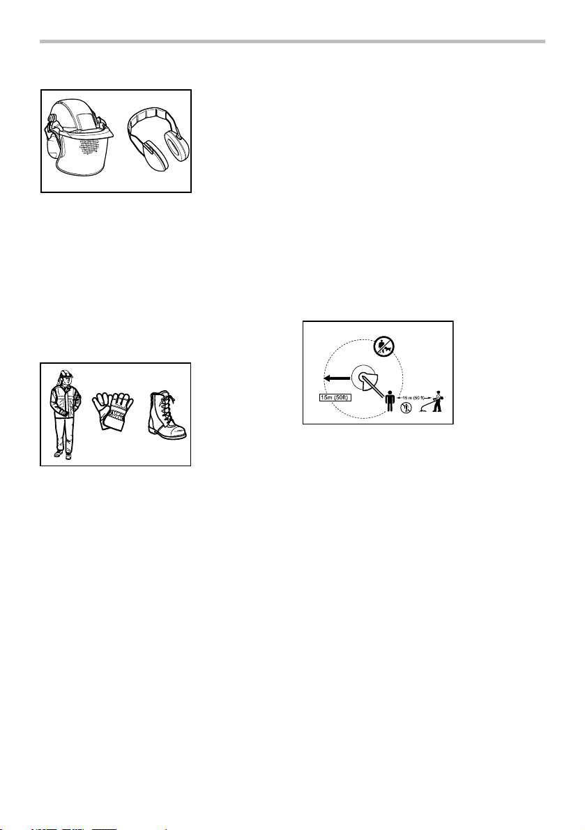
2. In order to avoid either head, eye, hand or foot
injuries as well as to protect your hearing the
following protective equipment and protective
installing the battery pack. Inserting the
battery pack into the string trimmer with the
switch on invites accidents.
clothing must be used during operation of the
equipment.
2
BL1830 / BL1830B /
BL1840 / BL1840B /
BL1850 / BL1850B /
BL1860B
Page 3
010820
3. Always wear a helmet where there is a risk of
falling objects. The protective helmet is to be
checked at regular intervals for damage and is to
be replaced at least every five years. Use only
approved protective helmets.
4. The visor of the helmet (or alternatively goggles)
protects the face from flying debris and stones.
During operation of the tool always wear goggles,
or a visor to prevent eye injuries.
5. Wear adequate noise protection equipment to
avoid hearing impairment (ear muffs , ear plugs
etc.).
4. When battery pack is not in use, keep it away
from other metal objects, like paper clips, coins,
keys, nails, screws or other small metal objects,
that can make a connection from one terminal to
another. Shorting the battery terminals together
may cause burns or a fire.
5. Under abusive conditions, liquid may be ejected
from the battery; avoid contact. If contact
accidentally occurs, flush with water. If liquid
contacts eyes, seek medical help. Liquid ejected
from the battery may cause irritation or burns.
6. Do not dispose of the battery(ies) in a fire. The
cell may explode. Check with local codes for
possible special disposal instructions.
7.
Do not open or mutilate the battery(ies). Released
electrolyte is corrosive and may cause damage to
the eyes or skin. It may be toxic if swallowed.
Starting up the tool
360°
010821
6. Work overalls protect against flying stones and
debris. It is strongly recommended that the user
wears work overalls.
7. Special gloves made of thick leather are part of
the prescribed equipment and must always be
worn during operation of the tool.
8. When using the tool, always wear sturdy shoes
with a nonslip sole. This protects against injuries
and ensures a good footing.
Electrical and battery safety
1. Avoid dangerous environment. Don't use the tool
in damp or wet locations or expose it to rain.
Water entering the tool will increase the risk of
electric shock.
2. Recharge only with the charger specified by the
manufacturer. A charger that is suitable for one
type of battery pack may create a risk of fire when
used with another battery pack.
3. Use power tools only with specifically designated
battery packs. Use of any other battery packs
may create a risk of injury and fire.
012858
1. Make sure that there are no children or other
people within a working range of 15 meters (50 ft),
also pay attention to any animals in the working
vicinity. Otherwise stop using the tool.
2.
Before use always check that the tool is safe for
operation. Check the security of the nylon cutting
head and the guard and the switch trigger/lever for
easy and proper action. Check for clean and dry
handles and test the on/off function of the switch.
3. Check damaged parts before further use of the
tool. A guard or other part that is damaged should
be carefully checked to determine that it will
operate properly and perform its intended
function. Check for alignment of moving parts,
binding of moving parts, breakage of parts,
mounting, and any other condition that may affect
its operation. A guard or other part that is
damaged should be properly repaired or replaced
by our authorized service center unless indicated
elsewhere in this manual.
4. Switch on the motor only when hands and feet
are away from the nylon cutting head.
5. Before starting make sure that the nylon cutting
head has no contact with hard objects such as
branches, stones etc. as the nylon cutting head
will revolve when starting.
3
Page 4

Method of operation
1. Only use the tool in good light and visibility.
During the winter season beware of slippery or
wet areas, ice and snow (risk of slipping). Always
ensure a safe footing.
2. Take care against injury to feet and hands from
the nylon cutting head.
3. Never cut above waist height.
4. Never stand on a ladder and run the tool.
5. Never climb up into trees to perform cutting
operation with the tool.
6. Never work on unstable surfaces.
7. Remove sand, stones, nails etc. found within the
working range. Foreign particles may damage the
nylon cutting head.
8. Should the nylon cutting head hit stones or other
hard objects, immediately switch off the motor
and inspect the nylon cutting head.
9. Before commencing cutting, the nylon cutting
head must have reached full working speed.
10. Operate the tool only with the shoulder harness
attached which is to be suitably adjusted before
putting the tool into operation. It is essential to
adjust the shoulder harness according to the user
size to prevent fatigue occurring during use.
11. During operation always hold the tool with both
hands. Never hold the tool with one hand during
use. Always ensure a safe footing.
12. The nylon cutting head has to be equipped with
the guard. Never run the tool with damaged
guards or without guards in place!
13. All protective equipment such as guards and the
shoulder harness supplied with the string trimmer
must be used during operation.
14. Except in case of emergency, never drop or cast
the tool to the ground or this may severely
damage the tool.
15. Never drag the tool on the ground when moving
from place to place, the tool may become
damaged if moved in this manner.
16. Always remove the battery cartridge from the tool:
− whenever leaving the tool unattended;
− before clearing a blockage;
− before checking, cleaning or working on the
tool;
− whenever the tool starts vibrating
abnormally;
− whenever transporting the tool.
17. Always ensure that the ventilation openings are
kept clear of debris.
Maintenance instructions
1. The condition of the nylon cutting head, protective
devices and shoulder harness must be checked
before commencing work.
2. Turn off the motor and remove the battery
cartridge before carrying out maintenance,
replacing the nylon cutting head or nylon cord
and cleaning the tool.
3. Check for loose fasteners and damaged parts
such as cracks in the nylon cutting head.
4. Follow instructions for lubricating and changing
accessories if applicable.
5. When not in use store the equipment in a dry
location that is locked up or out of children's
reach.
6. Use only the manufacturer's recommended
replacement parts and accessories.
7. Inspect and maintain the tool regularly, especially
before/after use. Have the tool repaired only by
our authorized service center.
8. Keep handles dry, clean and free from oil and
grease.
SAVE THESE INSTRUCTIONS.
WARNING:
DO NOT let comfort or familiarity with product
(gained from repeated use) replace strict adherence
to safety rules for the subject product. MISUSE or
failure to follow the safety rules stated in this
instruction manual may cause serious personal
injury.
WARNING:
Use of this product can create dust containing
chemicals which may cause respiratory or other
illnesses.
Some examples of these chemicals are compounds
found in pesticides, insecticides, fertilizers and
herbicides.
Your risk from these exposures varies, depending on
how often you do this type of work. To reduce your
exposure to these chemicals: work in a well ventilated
area, and work with approved safety equipment, such
as those dust masks that are specially designed to filter
out microscopic particles.
4
USG001-2
Page 5

USD301-5
Symbols
The followings show the symbols used for tool.
・ volts
・ direct current
・ no load speed
・ revolutions or reciprocation per minute
ENC007-10
IMPORTANT SAFETY
INSTRUCTIONS
FOR BATTERY CARTRIDGE
1. Before using battery cartridge, read all
instructions and cautionary markings on (1)
battery charger, (2) battery, and (3) product
using battery.
2. Do not disassemble battery cartridge.
3. If operating time has become excessively
shorter, stop operating immediately. It may
result in a risk of overheating, possible burns
and even an explosion.
4. If electrolyte gets into your eyes, rinse them
out with clear water and seek medical
attention right away. It may result in loss of
your eyesight.
5. Do not short the battery cartridge:
(1) Do not touch the terminals with any
conductive material.
(2) Avoid storing battery cartridge in a
container with other metal objects such
as nails, coins, etc.
(3) Do not expose battery cartridge to water
or rain.
A battery short can cause a large current flow,
overheating, possible burns and even a
breakdown.
6. Do not store the tool and battery cartridge in
locations where the temperature may reach or
exceed 50 ゚ C (122 ゚ F).
7. Do not incinerate the battery cartridge even if
it is severely damaged or is completely worn
out. The battery cartridge can explode in a fire.
8. Be careful not to drop or strike battery.
9. Do not use a damaged battery.
10. Follow your local regulations relating to
disposal of battery.
SAVE THESE INSTRUCTIONS.
CAUTION: Only use genuine Makita batteries.
Use of non-genuine Makita batteries, or batteries that
have been altered, may result in the battery bursting
causing fires, personal injury and damage. It will also
void the Makita warranty for the Makita tool and charger.
Tips for maintaining maximum battery life
1. Charge the battery cartridge before
completely discharged.
Always stop tool operation and charge the
battery cartridge when you notice less tool
power.
2. Never recharge a fully charged battery
cartridge.
Overcharging shortens the battery service life.
3. Charge the battery cartridge with room
temperature at 10 ゚ C - 40 ゚ C (50 ゚ F - 104 ゚ F).
Let a hot battery cartridge cool down before
charging it.
4. Charge the battery cartridge if you do not use
it for a long period (more than six months).
5
Page 6
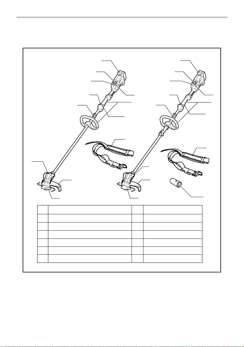
PARTS DESCRIPTION
13
DUR182L
6
10
9
11
1
Battery cartridge
2
Speed adjusting dial
3
Indication lamp
4
Power button
Lock-off lever
5
Hanger (suspension point)
6
7
Grip
1
2
3
5
7
8
12
DUR183L
4
6
10
9
11
Switch trigger
8
9
Guard
Wire guard
10
Cutting tool
11
Shoulder harness
12
13
Cap
1
2
3
5
13
13
4
7
8
12
014161
6
Page 7
FUNCTIONAL DESCRIPTION
WARNING:
• Always be sure that the tool is switched off
and battery cartridge is removed before
adjusting or checking the functions on the
trimmer. Failure to switch off and remove the
battery cartridge may result in serious personal
injury from accidental start-up.
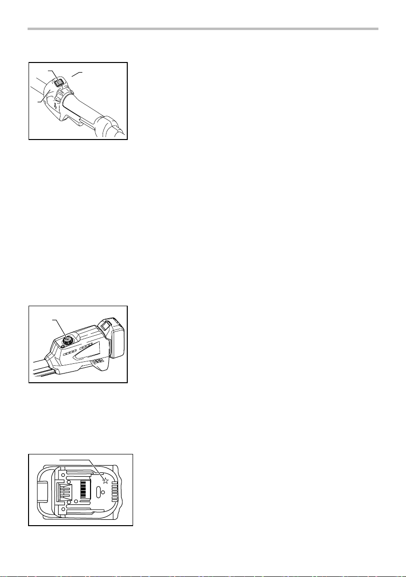
Installing or removing battery cartridge
1. Red indicator
1
013921
CAUTION:
• Always switch off the tool before installing or
removing of the battery cartridge.
• Hold the tool and the battery cartridge firmly
when installing or removing battery cartridge.
Failure to hold the tool and the battery cartridge
firmly may cause them to slip off your hands and
result in damage to the tool and battery cartridge
and a personal injury.
To remove the battery cartridge, slide it from the tool
while sliding the button on the front of the cartridge.
To install the battery cartridge, align the tongue on the
battery cartridge with the groove in the housing and slip
it into place. Insert it all the way until it locks in place
with a little click. If you can see the red indicator on the
upper side of the button, it is not locked completely.
CAUTION:
• Always install the battery cartridge fully until the
red indicator cannot be seen. If not, it may
accidentally fall out of the tool, causing injury to
you or someone around you.
• Do not install the battery cartridge forcibly. If the
cartridge does not slide in easily, it is not being
inserted correctly.
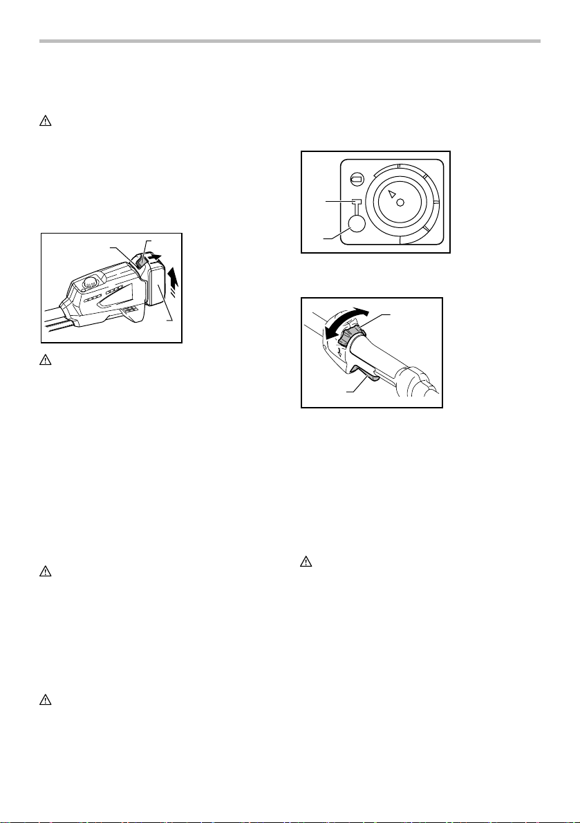
Power switch action
WARNING:
• Before inserting the battery cartridge in the
trimmer, always check to see that the switch
trigger actuates properly and returns to the
"OFF" position when released. Do not pull the
2
2. Button
3. Battery cartridge
3
switch trigger hard without turning the lock-off
lever. This can cause switch breakage.
Operating a tool with a switch that does not
actuate properly can lead to loss of control and
serious personal injury.
1. Power indicator
2. Power button
1
2
013834
Push the power button on the housing so that the tool is
powered on and power indicator lights.
1. Lock-off lever
1
2. Switch trigger
2
014158
To prevent the switch trigger from being accidentally
pulled, a lock-off lever is provided.
To start the tool, turn the lock-off lever and then pull the
switch trigger. Release the switch trigger to stop.
NOTE:
• After the power button is pushed and the tool is
left one minute without any operations, the tool is
automatically powered off.
Reversing Switch for Debris Removal
WARNING:
• Always be sure that the tool is switched off
and battery cartridge is removed before
removing weeds or debris entangled in the
trimmer that could not be removed when
operated in the reverse mode. Failure to switch
off and remove the battery cartridge may result in
serious personal injury from accidental start-up.
7
Page 8
1
A
2
014159
This trimmer has a reversing switch which is only
provided to change the direction of rotation so that it can
be used to remove weeds and debris entangled in the
trimmer. To operate the tool normally the "A" side of the
switch should be depressed.
To remove weeds and debris that are jammed in the
rotating head the tool can be reversed by depressing
the "B" side of the switch. In the reverse position the
tool will only operate for a short period of time and
automatically shut off.
NOTICE:
•
Always check the direction of rotation before operation.
• Use the reversing switch only after the trimmer
comes to a complete stop. Changing the direction
of rotation before the trimmer stops may damage
the tool.
3
B
1. Reversing switch
2. A position
depressed for
normal operation
3. B position
depressed for
weed and debris
removal
Speed adjusting dial
1. Speed adjusting
1
013922
The trimmer speed can be infinitely adjusted from 3,500
/min to 6,000 /min with the speed adjusting dial.
Turn the speed adjusting dial clockwise for higher speed,
and counterclockwise for lower speed.
dial
Battery protection system
(Lithium-ion battery with star marking)
1
012128
1. Star marking
Lithium-ion batteries with a star marking are equipped
with a protection system. This system automatically cuts
off power to the tool to extend battery life.
The tool will automatically stop during operation if the
tool and/or battery are placed under one of the following
conditions:
• Overloaded:
The tool is operated in a manner that causes
it to draw an abnormally high current.
In this situation, release the switch trigger on
the tool and stop the application that caused
the tool to become overloaded. Then pull the
switch trigger again to restart.
If the tool does not start, the battery is
overheated. In this situation, let the battery
cool before pulling the switch trigger again.
• Low battery voltage:
The remaining battery capacity is too low
and the tool will not operate. In this situation,
remove and recharge the battery.
8
Page 9
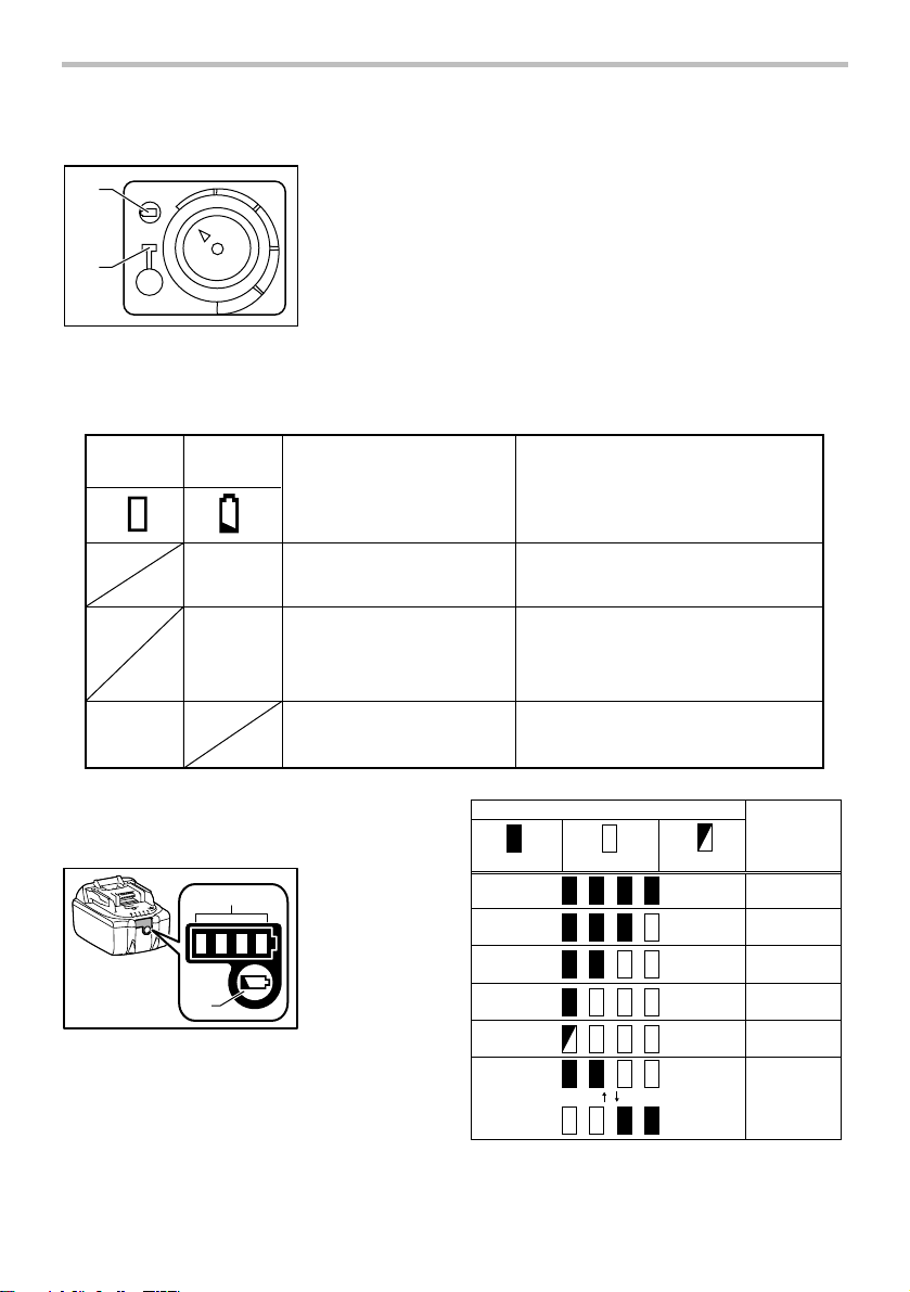
Indication lamps
1
2
013836
When the protection system works during the operation,
the lamps light up.
Refer to the following table for the status and action to
be taken for the indication lamp.
1. Battery indicator
2. Power indicator
Power
indicator
Battery
indicator
Status
Blinking
Battery power has been
nearly used up.
Battery protector is
Lighting Up
shutting off the power battery power has been
used up.
Blinking
013900
Overheat protector is shutting
off the power - overheating.
Indicating the remaining battery capacity
(Only for battery cartridges with "B" at the end of the
model number.)
1. Indicator lamps
1
2
015676
Press the check button on the battery cartridge to
indicate the remaining battery capacity. The indicator
lamps light up for few seconds.
2. CHECK button
Action to be taken
Replace the battery with fully charged one.
Replace the battery with fully charged one.
Rest and cool down the equipment
for a while.
Indicator lamps
Off
015658
BlinkingLighted
Remaining
capacity
75% to 100%
50% to 75%
25% to 50%
0% to 25%
Charge the
battery.
The battery
may have
malfunctioned.
9
Page 10
NOTE:
• Depending on the conditions of use and the
ambient temperature, the indication may differ
slightly from the actual capacity.
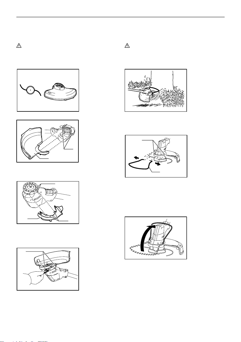
Nylon cutting head
NOTICE:
• Do not attempt to bump feed the head while the
trimmer is operating at a high RPM. Bump feeding
at a high RPM may cause damage to the nylon
cutting head.
• The bump feed will not operate properly if the
head is not rotating.
1. Most effective
1
cutting area
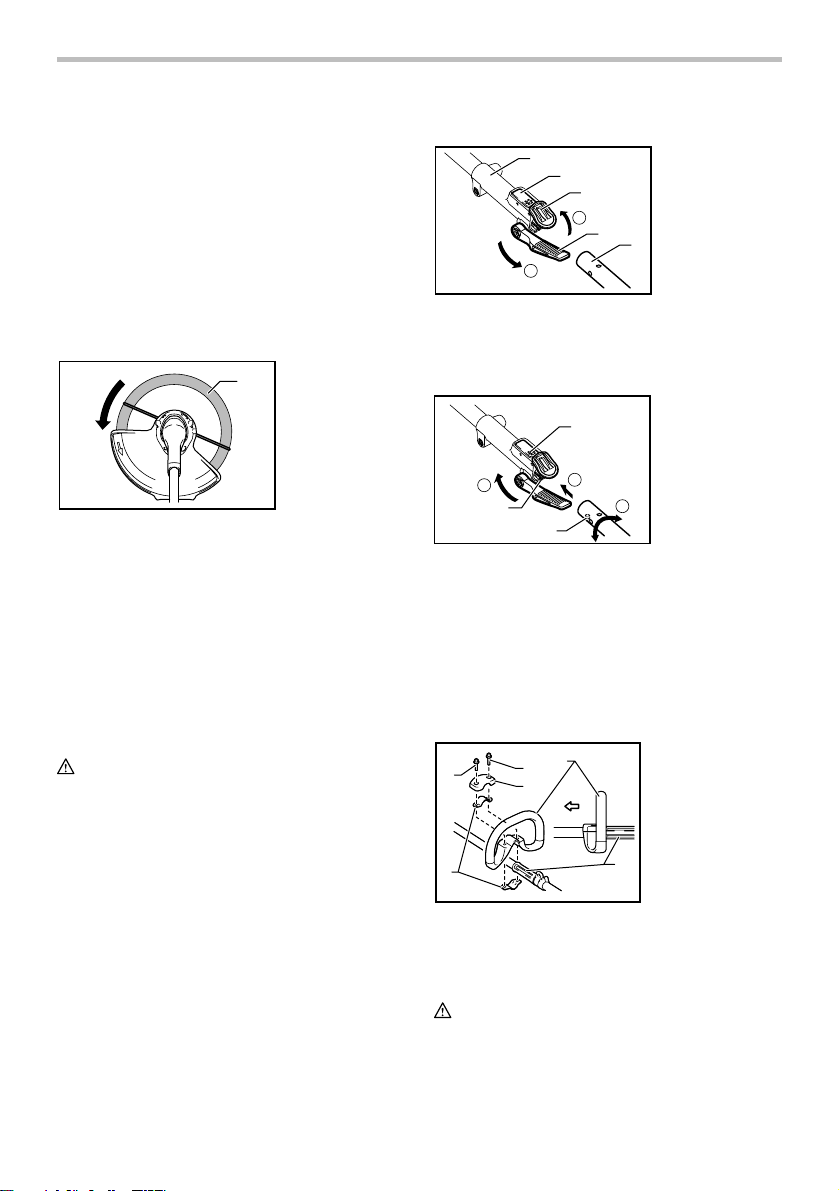
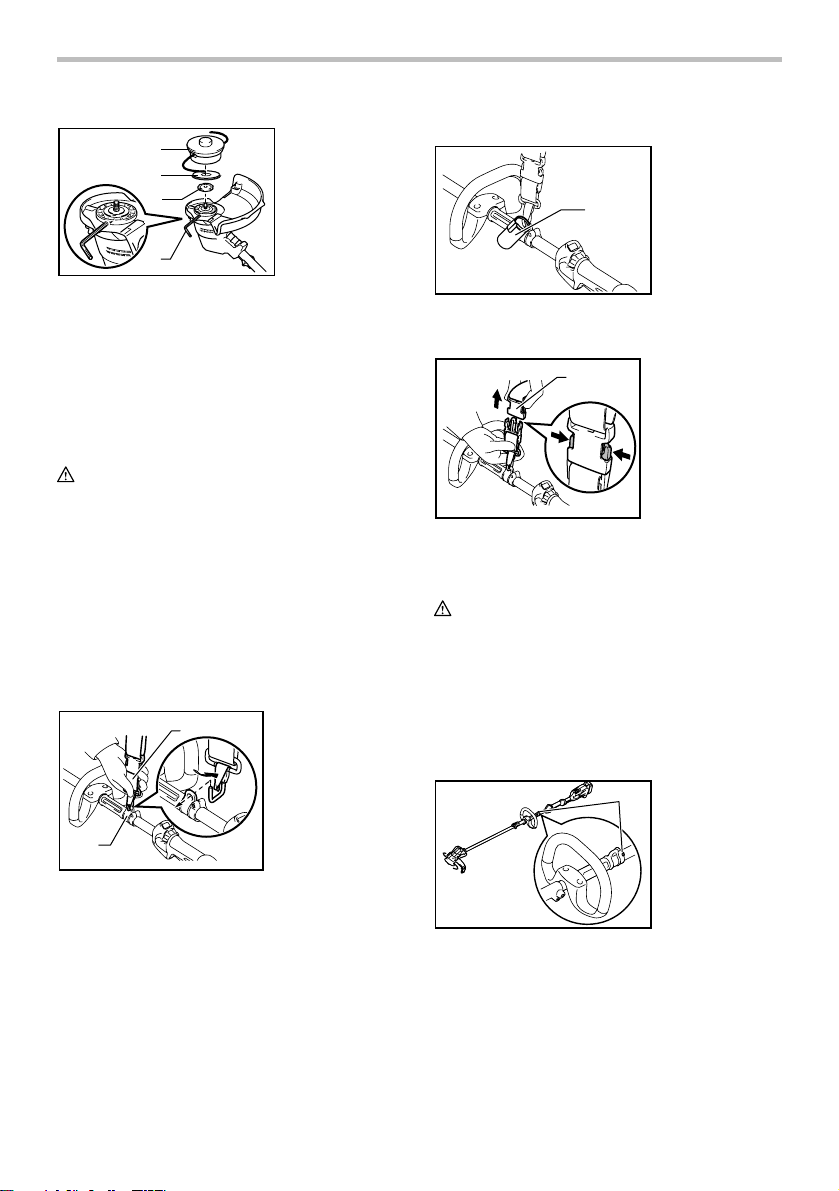
For Model DUR183L
1
2
3
2
4
1
013831
1. Joint
2. Lock lever
3. Joint cover
4. Lever
5. Pipe (Cutting
tool side)
5
To mount the attachment to a power unit:
1. Make sure that the lever is not tightened.
2. To open the entrance of the joint, depress the
joint cover.
1. Lock lever
1
2. Concave portion
3. Protrusion
013811
The nylon cutting head is a dual grass trimmer head
provided with a bump & feed mechanism.
To cause the nylon cord to feed out, the cutting head
should be bumped against the ground while rotating at a
low RPM.
NOTE:
If the nylon cord does not feed out while bumping the
head, rewind/replace the nylon cord by following the
procedures described under “Maintenance.”
ASSEMBLY
WARNING:
• Always be sure that the tool is switched off
and battery cartridge is removed before
carrying out any work on the trimmer. Failure to
switch off and remove the battery cartridge may
result in serious personal injury from accidental
start-up.
• Never start the tool unless it is completely
assembled. Operation of the tool in a partially
assembled state may result in serious personal
injury from accidental start-up.
5
2
013832
4
3
3
3. Align the protrusion on the pipe (cutting tool side )
with the concave portion of the joint part.
4. Insert the attachment pipe into the joint part.
Make sure that the surface of the lock lever is
horizontal to the pipe.
5. Tighten the lever firmly as shown.
To remove the attachment, loosen the lever, press the
front part of the lock lever and then slide the pipe.
Installing the grip
1
2
2
3
5
4
014155
Fit the grip onto the shaft pipe and tighten it with two
hex bolts. Make sure that the spacer on the shaft pipe is
located between the grip assembly and the other grip.
Do not remove or shrink the spacer.
CAUTION:
• For model DUR183L, never install the grip on the
joint.
1. Grip
2. Hex bolts
3. Cover
4. Clamps
5. Cutting tool side
6. Spacer
6
10
Page 11
Installing the guard
WARNING:
• Never use the trimmer without the guard in
place. Failure to do so can cause serious personal
injury.
Installing the wire guard
CAUTION:
• Before adjusting the wire guard, wait for the
cutting head comes to standstill. Do not adjust the
wire guard with your foot.
013813
2
013839
1. Grooves
2. Protector
1
Align the protrusions on the protector with the grooves
of the motor housing.
1
2
013838
1. Concave
portions
2. Protector holder
3. Protrusions
3
Align the protrusions on the protector holder with the
concave portions of the motor housing. Insert the
protector holder to the motor housing.
1
014185
1. Hex bolts
After attaching the protector and the protector holder to
the motor housing, tighten the hex bolts securely.
013843
To reduce the risk damaging the objects in front of the
cutting head, insert the wire guard so that it controls the
cutting range of the mowing line.
1
2
013841
1. Holes
2. Wire guard
Slightly expand the wire guard outward and then insert it
into the holes of the protector.
NOTE:
• Do not expand the wire guard outward too much.
Otherwise it may break.
013842
When wire guard is not in use, lift it for the idle position.
Installing nylon cutting head
NOTICE:
• Be sure to use genuine Makita nylon cutting head.
Turn the tool upside down so that you can replace the
nylon cutting head easily.
11
Page 12
1
2
3
1. Nylon cutting
head
2. Metal guard
3. Receive washer
4. Hex wrench
For Model DUR183L
1. Cap
1
4
013817
Insert the hex wrench through the hole on the protector
cover and the motor housing and rotate the receive
washer until it is locked with the hex wrench. Mount the
metal guard, the nylon cutting head onto the threaded
spindle directly and tighten it by turning it
counterclockwise. Remove the hex wrench.
To remove the nylon cutting head, turn the nylon cutting
head clockwise while holding the receive washer with
the hex wrench.
CAUTION:
• If during operation the nylon cutting head
accidentally impacts a rock or hard object the
trimmer should be stopped and inspected for
any damage. If the nylon cutting head is
damaged it should be replaced immediately.
Use of a damaged nylon cutting head could result
in serious personal injury.
OPERATION
Correct handling of tool
Attachment of shoulder harness
1
1. Buckle
2. Hook
014165
When the cap is not in use, hang it on the hook.
Detachment
1
014157
The buckle is provided with a means of quick release.
Simply squeeze the sides and the buckle to release the
tool.
WARNING:
• Be extremely careful to maintain control of the
trimmer at all times. Do not allow the trimmer
to be deflected toward you or anyone in the
work vicinity. Failure to keep control of the
trimmer could result in serious injury to the
bystander and the operator.
Adjustment of the hanger position and shoulder
harness
1. Buckle
1. Hex bolt
1
2
014156
Put the shoulder harness on. Then connect the buckles
on both the hook and the harness. Be sure that the
buckles click and lock completely in place.
014164
To change the hanger position, loosen the hex bolt on
the hanger with the supplied wrench. Then move the
hanger.
After adjusting the hanger position, tighten the hex bolt
with the wrench securely.
12
Page 13
MAINTENANCE
WARNING:
• Always be sure that the tool is switched off
and battery cartridge is removed before
attempting to perform inspection or
maintenance on the trimmer. Failure to switch
off and remove the battery cartridge may result in
serious personal injury from accidental start-up.
NOTICE:
Never use gasoline, benzine, thinner, alcohol or
the like. Discoloration, deformation or cracks may
result.
Replacing the nylon cord
WARNING:
• Make sure that the cover of the nylon cutting
head is secured to the housing properly as
described below. Failure to properly secure the
cover may cause the nylon cutting head to fly
apart resulting in serious personal injury.
• Use only 2.0 - 3.0 mm (0.08" - 0.12") diameter
nylon cord. Never use metal wire, rope or the
like. Use of something other than the
recommended nylon cord may cause damage to
the trimmer and result in serious personal injury.
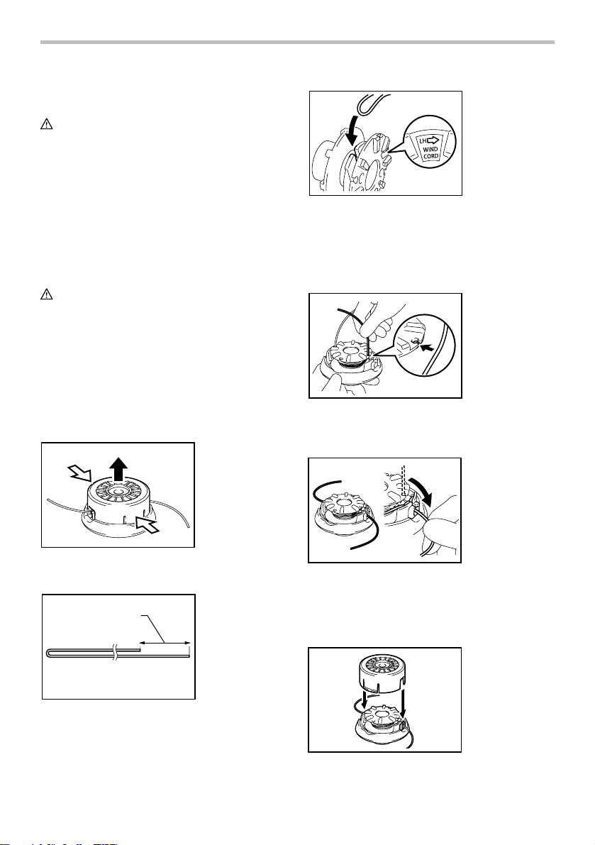
013824
Hook the middle of the new nylon cord to the notch
located at the center of the spool between the 2
channels provided for the nylon cord.
Wind both ends firmly around the spool in the direction
marked on the head for left hand direction indicated by
LH.
013825
Wind all but about 100 mm (4") of the cords, leaving the
ends temporarily hooked through a notch on the side of
the spool.
013822
Take off cover from housing, pressing two latches which
are slotted section oppositely on side of housing.
1
013823
Cut a nylon line in 3-6m (10 - 20 ft). Fold the cutting line
in two halves, leave one of half longer 80-100 mm (3 - 4
inches) than another.
1. 80-100 mm
013826
Mount the spool on the cover so that the grooves and
protrusions on the spool match up with those on the
cover. Now, unhook the ends of the cord from their
temporary position and feed the cords through the
eyelets to come out of the cover.
013827
13
Page 14

Align the protrusion on the underside of the cover with
the slots of the eyelets. Then push the cover firmly onto
the housing to secure it. Make sure the latches fully
spread in the cover.
To maintain product SAFETY and RELIABILITY, repairs,
any other maintenance or adjustment should be
performed by Makita Authorized or Factory Service
Centers, always using Makita replacement parts.
TROUBLE SHOOTING
Before asking for repairs, first, conduct your own
inspection. If you find a problem that is not explained in
the manual, do not attempt to dismantle the tool.
Instead, ask Makita Authorized or Factory Service
Centers, always using Makita replacement parts.
Malfunction status
Motor does not run.
Motor stops running after
a little use.
It does not reach maximum
RPM.
Cutting tool does not rotate:
stop the machine immediately!
Abnormal vibration:
stop the machine immediately!
Cutting tool and motor
stop:
Remove the battery
immediately!
010856
cannot
Cause
Battery cartridge is not installed.
Battery problem (under voltage)
The drive system does not work
correctly.
Rotation is in reverse.
Battery's charge level is low.
Overheating.
Battery is installed improperly.
Battery power is dropping.
The drive system does
not work correctly.
Foreign object such as a branch
is jammed between the guard
the nylon cutting head.
The drive system does not work
correctly.
One end of the nylon cord has
been broken.
The drive system does not work
correctly.
Electric or electronic malfunction.
and
Action
Install the battery cartridge.
Recharge the battery. If recharging
is not effective, replace
Ask your local authorized service
center for repair.
Change the direction of ratation
with the reversing switch.
Recharge the battery. If recharging
is not effective, replace battery.
Stop using of tool to allow it to cool
down.
Install the battery cartr
described in this manual.
Recharge the battery. If recharging
is not effective, replace battery.
Ask your local authorized service
center for repair.
Remove
the foreign object.
Ask your local authorized service
center for repair.
Bump the nylon cutting head
against the ground while it is
rotating to cause the cord to feed.
Ask your local authorized service
center for repair.
Remove the battery and ask your
local authorized service center for
repair.
battery.
idge as
14
Page 15

OPTIONAL ACCESSORIES
WARNING:
• Do not mount a blade on this string trimmer
and only use the recommended accessories or
attachments indicated in this manual. The use
of a blade or any other accessory or attachment
may result in serious personal injury.
If you need any assistance for more details regarding
these accessories, ask your local Makita Service Center.
• Nylon cutting head
• Nylon cord (cutting line)
• Shoulder harness
• Hex wrench
• Makita genuine battery and charger
NOTE:
• Some items in the list may be included in the tool
package as standard accessories. They may differ
from country to country.
MAKITA LIMITED ONE YEAR WARRANTY
Warranty Policy
Every Makita tool is thoroughly inspected and tested
before leaving the factory. It is warranted to be free of
defects from workmanship and materials for the period
of ONE YEAR from the date of original purchase.
Should any trouble develop during this one year period,
return the COMPLETE tool, freight prepaid, to one of
Makita’s Factory or Authorized Service Centers. If
inspection shows the trouble is caused by defective
workmanship or material, Makita will repair (or at our
option, replace) without charge.
This Warranty does not apply where:
repairs have been made or attempted by others:
repairs are required because of normal wear and
tear:
the tool has been abused, misused or improperly
maintained:
alterations have been made to the tool.
IN NO EVENT SHALL MAKITA BE LIABLE FOR ANY
INDIRECT, INCIDENTAL OR CONSEQUENTIAL
DAMAGES FROM THE SALE OR USE OF THE
PRODUCT. THIS DISCLAIMER APPLIES BOTH
DURING AND AFTER THE TERM OF THIS
WARRANTY.
MAKITA DISCLAIMS LIABILITY FOR ANY IMPLIED
WARRANTIES, INCLUDING IMPLIED WARRANTIES
OF "MERCHANTABILITY" AND "FITNESS FOR A
SPECIFIC PURPOSE," AFTER THE ONE YEAR TERM
OF THIS WARRANTY.
This Warranty gives you specific legal rights, and you
may also have other rights which vary from state to
state. Some states do not allow the exclusion or
limitation of incidental or consequential damages, so
the above limitation or exclusion may not apply to you.
Some states do not allow limitation on how long an
implied warranty lasts, so the above limitation may not
apply to you.
EN0006-1
15
Page 16

FRANÇAIS (Mode d’emploi original)
SPÉCIFICATIONS
Modèle DUR182L DUR183L
Type de tube Tube intégré Tube démontable
Vitesse à vide (RPM) 3 500 - 6 000 /min
Longueur totale avec tête à fils de nylon 1 843 mm (72-1/2")
Diamètre de coupe avec la tête à fils de nylon 300 mm (11-3/4")
Avertissement : Utilisez seulement la/les batterie(s) décrite(s).
• Étant donné l'évolution constante de notre programme de recherche et de développement, les spécifications contenues dans ce
manuel sont sujettes à modification sans préavis.
• Les caractéristiques techniques et la batterie peuvent varier suivant les pays.
• Poids, batterie comprise, conforme à la procédure EPTA de 01/2003
CONSIGNES DE SÉCURITÉ
IMPORTANTES
AVERTISSEMENT! Veuillez lire toutes les mises en
garde de sécurité et toutes les instructions.
des mises en garde et des instructions comporte un risque
de décharge électrique, d’incendie et/ou de blessure grave.
Conservez toutes les mises en
garde et instructions pour
référence future.
Consignes générales
1. Ne laissez pas les personnes ne sachant pas
utiliser le taille-bordures ou n’ayant pas
connaissance des présentes instructions utiliser
l’outil. Les taille-bordures peuvent être dangereux
s’ils sont utilisés par des utilisateurs non formés.
2. Assurez-vous qu’avant de manipuler le taillebordures, l’utilisateur a lu le mode d’emploi.
3. Utilisez le taille-bordures avec le maximum de
soin et d’attention.
4.
Utilisez le taille-bordures seulement si vous êtes en
bonne forme physique. Manipulez délicatement et
soigneusement la machine. Faites preuve de bon
sens et rappelez-vous que l’utilisateur est
responsable des accidents ou des dangers auxquels
il expose les autres personnes ou leurs biens.
5. N’utilisez jamais le taille-bordures en cas de
fatigue, de maladie, ni sous l'influence de l'alcool
ou de médicaments.
Longueur divisée - 982 mm (38-3/4")
Poids net
Tension nominale C.C. 18 V
Batterie(s) standard
3,6 kg (8,0 lbs) 3,9 kg (8,6 lbs) 3,9 kg (8,5 lbs) 4,1 kg (9,1 lbs)
BL1815N /
BL1820 /
BL1820B
USB108-1
BL1830 / BL1830B /
BL1840 / BL1840B /
BL1850 / BL1850B /
BL1860B
BL1815N /
BL1820 /
BL1820B
6. Évitez les démarrages accidentels :
BL1830 / BL1830B /
BL1840 / BL1840B /
BL1850 / BL1850B /
− Avant d’installer la batterie, vérifiez que le
commutateur est en position OFF. Si vous
insérez la batterie dans le taille-bordures
alors que le commutateur est en position ON,
L’ignorance
vous risquez de provoquer un accident.
− Ne transportez pas le taille-bordures alors
que vous doigt est sur le commutateur; vous
risquez de provoquer un accident.
7. En cas de fonctionnement anormal, éteignez
immédiatement le taille-bordures.
8. Retirez la batterie du taille-bordures avant de
procéder à des réglages, au remplacement
d’accessoires ou à son rangement. De telles
mesures de prévention réduisent le risque de
démarrage accidentel du taille-bordures.
9. Ne forcez pas l’outil, il fonctionnera mieux et en
présentant moins de risque de blessure si vous
respectez la vitesse de travail pour laquelle il a
été conçu.
10. Restez en bonne position d'équilibre. Maintenez
en permanence un équilibre stable.
Utilisation normale de l’outil
1. Utilisez l’outil correctement. Le coupe herbe
sans-fil est seulement conçu pour couper l'herbe
et les mauvaises herbes fines. Il ne doit pas être
utilisé à toute autre fin comme le dressage de
bordures ou encore pour tailler les haies. Cela
représente un risque de blessure.
Équipement de protection personnel
1. Vêtissez-vous correctement. La tenue portée doit
être fonctionnelle et appropriée, autrement dit elle
16
BL1860B
Page 17

doit être ajustée et ne pas entraver les
mouvements. Ne portez pas de bijoux ni de
vêtements qui pourraient s'accrocher dans les
buissons ou les arbustes. Si vos cheveux sont
longs, recouvrez-les d’un filet de protection.
2. Afin d'éviter les blessures à la tête, aux yeux, aux
mains ou aux pieds et de protéger votre ouïe,
vous devez porter l'équipement et les vêtements
de protection indiqués ci-dessous lorsque vous
manipulez l’équipement.
010820
3.
Portez toujours un casque s'il y a un risque de
projection d'objets. Le casque de protection doit
être inspecté régulièrement pour s’assurer qu’il ne
présente pas de dommages et il doit être remplacé
au moins tous les 5 ans. Utilisez uniquement des
casques de protection homologués.
4.
La visière-écran du casque (ou à défaut les lunettes
étanches) protège le visage des projections de
débris et de pierres. Portez toujours des lunettes
étanches ou une visière lorsque vous utilisez l’outil,
afin de prévenir les blessures aux yeux.
5. Portez un équipement antibruit adéquat afin
d'éviter une perte auditive (protège-oreilles,
bouchons d'oreilles, etc.).
Consignes de sécurité concernant
l’alimentation et la batterie
1. Évitez les environnements dangereux. N’utilisez
pas l’outil dans les endroits humides ou mouillés
et ne l’exposez pas à la pluie. L’infiltration d’eau
dans un outil accroît le risque de décharge
électrique.
2. Ne la rechargez qu’avec le chargeur spécifié par
le fabricant. Un chargeur conçu pour un certain
type de batterie risque de déclencher un incendie
s’il est utilisé avec une autre batterie.
3. N’utilisez les outils électriques qu’avec leurs
batteries spécifiques. Les autres batteries
risqueraient de vous blesser ou de provoquer un
incendie.
4. Lorsque la batterie n’est pas utilisée, tenez-la à
distance des objets métalliques tels que
trombones, pièces de monnaie, clés, clous, vis ou
autres petits objets métalliques, conducteurs
potentiels entre une borne et une autre. Un courtcircuit entre les bornes de la batterie peut
provoquer des brûlures ou un incendie.
5. Dans des conditions d’utilisation inadéquates de
la batterie, il peut y avoir fuite d’électrolyte. En
cas de contact accidentel, rincez avec beaucoup
d’eau. Si du liquide entre en contact avec les
yeux, consultez un médecin. Le liquide qui gicle
de la batterie peut provoquer des irritations ou
des brûlures.
6. Ne jetez pas la/les batterie(s) dans le feu.
L’élément pourrait exploser. Vérifiez la
réglementation de votre région pour savoir s’il
existe des directives particulières qui s’appliquent
à l’élimination des batteries.
7. N’ouvrez pas et n’endommagez pas la/les
batterie(s). L’électrolyte qui s’échappe est corrosif
et peut provoquer des dommages aux yeux ou à
la peau. Il peut être toxique s’il est ingéré.
Démarrage de l’outil
010821
6. Les combinaisons de travail vous protègent des
projections de débris et de pierres. Il est vivement
conseillé à l'utilisateur de porter une combinaison
de travail.
7.
Parmi l'équipement recommandé, on trouve également
des gants spéciaux en cuir épais, qui devraient être
toujours portés lors de l'utilisation de l’outil.
8. Lorsque vous utilisez l’outil, portez toujours des
chaussures robustes dotées d’une semelle
antidérapante. Cela vous préservera des
blessures et vous assurera une bonne stabilité.
360°
012858
1. Veillez à éloigner les enfants ou toute autre
personne dans une zone de travail de 15 mètres,
et faites également attention aux animaux
présents dans cette zone. Si cette zone de
sécurité n’est pas respectée, n’utilisez pas l’outil.
17
Page 18

2. Avant de l’utiliser, vérifiez toujours que l’outil est
en bonne condition. Vérifiez si la tête à fils de
nylon et le protecteur sont sûrs et si le levier/la
gâchette du commutateur fonctionne librement et
adéquatement. Vérifiez si les poignées sont
propres et sèches, et testez le fonctionnement du
commutateur marche/arrêt.
3.
Vérifiez si des pièces sont endommagées avant de
continuer à utiliser l’outil. Si un protecteur ou toute
autre pièce est endommagée, examinez-la
attentivement pour vérifier si elle fonctionnera
adéquatement et sera en mesure de remplir sa
fonction. Vérifiez tous les éléments pouvant affecter
le bon fonctionnement de l’outil : l’alignement des
pièces en mouvement, l’absence de grippage ou de
pièces fissurées, le montage des pièces, etc. Toute
pièce endommagée (protecteur, etc.) doit être
correctement réparée ou remplacée par notre centre
de service après-vente agréé, à moins d’indication
contraire dans le présent mode d’emploi.
4. N’allumez le moteur qu’une fois vos mains et vos
pieds à distance de la tête à fils de nylon.
5. Avant de démarrer l’outil, veillez à ce que la tête
à fils de nylon ne touche pas d’objets durs tels
que des branches, des pierres, etc., cela pourrait
la faire basculer au démarrage.
Mode de fonctionnement
1. Utilisez l’outil seulement avec un bon éclairage et
dans de bonnes conditions de visibilité. En hiver,
faites attention aux sols glissants et aux zones
humides, à la glace et à la neige (risque de
glissade). Assurez-vous toujours de votre stabilité.
2. Attention à ne pas vous blesser aux pieds et aux
mains avec la tête à fils de nylon.
3. Ne réalisez jamais de coupe en tenant la
machine plus haut que votre taille.
4.
N’utilisez jamais l’outil en vous tenant sur une échelle.
5. Ne réalisez jamais de coupe avec l’outil en étant
perché dans un arbre.
6. Ne travaillez pas sur des surfaces instables.
7. Retirez le sable, les pierres, les clous, etc. qui se
trouvent dans la zone d'utilisation de la machine.
Des corps étrangers pourraient endommager la
tête à fils de nylon.
8. Si la tête à fils de nylon heurte des pierres ou des
objets durs, coupez immédiatement le moteur et
inspectez la tête à fils de nylon.
9. Avant de commencer la coupe, la tête à fils de
nylon doit avoir atteint sa pleine vitesse de travail.
10.
Utilisez l’outil seulement après avoir mis la sangle
d’épaule; qui doit être réglée adéquatement avant
que l’outil ne soit mis en marche. La sangle
d'épaule doit être ajustée en fonction de la taille de
l'utilisateur, afin d'éviter une fatigue à l'utilisation.
11. Tenez toujours l’outil à deux mains lorsqu’il est en
marche. Ne tenez jamais l'outil d’une seule main
lorsqu’il est en marche. Assurez-vous toujours de
votre stabilité.
12.
La tête à fils de nylon doit être équipée du protecteur.
N’utilisez jamais l’équipement si le protecteur est
endommagé ou s’il n'est pas en place!
13.
Tout équipement de protection, notamment les
protecteurs et la sangle d’épaule fournis avec le taillebordures, doit être utilisé lors du fonctionnement.
14. Sauf en cas d’urgence, ne faites jamais tomber
l’outil ou ne le lancez pas par terre; cela risque de
gravement l’endommager.
15. Ne traînez jamais l’outil sur le sol lorsque vous
allez d’un endroit à l’autre, car cela risquerait de
l’endommager.
16. Retirez toujours la batterie de l’outil :
− chaque fois que vous laissez l’outil sans
surveillance;
− avant de le débloquer;
− avant d’examiner l’outil, de le nettoyer ou
d’effectuer des travaux;
− chaque fois que l’outil vibre de façon anormale;
− lorsque l’outil est transporté.
17. Assurez-vous toujours que les orifices de
ventilation ne présentent pas de débris.
Consignes d'entretien
1. L’état de la tête à fils de nylon, des dispositifs de
protection et de la sangle d’épaule doit être
inspecté avant de commencer à travailler.
2. Éteignez le moteur et retirez la batterie avant de
réaliser tout travail d’entretien, de remplacer la
tête à fils de nylon ou le fil de nylon, ou de
nettoyer l’outil.
3. Assurez-vous qu’il n’y a pas d’attaches mal
serrées ni de pièces endommagées, comme des
fissures sur la tête à fils de nylon.
4. Suivez les instructions concernant le graissage et
le remplacement des accessoires, s’il y a lieu.
5. Lorsque vous ne l’utilisez pas, rangez
l’équipement dans un lieu sec, hors de la portée
des enfants.
6. N’utilisez que les pièces de rechange et les
accessoires recommandés par le fabricant.
7. Procédez régulièrement à l'inspection et à
l'entretien de l'outil, particulièrement avant/après
l'utilisation. Ne confiez les réparations de l’outil
qu’aux centres de service après-vente agréés.
8. Gardez les poignées de l’outil sèches, propres et
sans trace d’huile ou de graisse.
CONSERVEZ CE MODE
D'EMPLOI.
18
Page 19

AVERTISSEMENT:
NE VOUS LAISSEZ PAS tromper (au fil d'une
utilisation répétée) par un sentiment d'aisance ou
de familiarité avec le produit en négligeant les
consignes de sécurité qui accompagnent le produit.
L'utilisation non sécuritaire ou incorrecte de cet
outil comporte un risque de blessure grave.
AVERTISSEMENT:
L'utilisation de ce produit peut lever une poussière
contenant des produits chimiques susceptibles
d'entraîner des troubles respiratoires ou d'autres
maladies.
Parmi ces produits chimiques, on trouve des
composants de pesticides, insecticides, engrais et
herbicides.
Les risques varient en fonction de la fréquence à
laquelle vous utilisez l'outil. Pour réduire les risques liés
à l'exposition à ces produits chimiques : travaillez dans
une pièce bien ventilée et portez des dispositifs de
sécurité homologués, tels que des masques
antipoussières spécialement conçus pour filtrer les
particules microscopiques.
USG001-2
USD301-5
Symboles
Les symboles utilisés pour l'outil sont indiqués cidessous.
・ volts
・ courant continu
・ vitesse à vide
・ tours ou alternances par minute
ENC007-10
CONSIGNES DE SÉCURITÉ
IMPORTANTES
POUR LA BATTERIE
1. Avant d'utiliser la batterie, lisez toutes les
instructions et précautions relatives (1) au
chargeur de batterie, (2) à la batterie, et (3) à
l'outil utilisant la batterie.
2. Ne démontez pas la batterie.
3. Cessez immédiatement l'utilisation si le temps
de fonctionnement devient excessivement
court. Il y a risque de surchauffe, de brûlures,
voire d'explosion.
4. Si l'électrolyte pénètre dans vos yeux, rincezles à l'eau claire et consultez immédiatement
un médecin. Il y a risque de perte de la vue.
5. Ne court-circuitez pas la batterie :
(1) Ne touchez les bornes avec aucun
matériau conducteur.
(2) Évitez de ranger la batterie dans un
conteneur avec d'autres objets
métalliques, par exemple des clous, des
pièces de monnaie, etc.
(3) Évitez d'exposer la batterie à l'eau ou à la
pluie.
Un court-circuit de la batterie pourrait
provoquer un fort courant, une surchauffe,
parfois des brûlures et même une panne.
6. Ne rangez pas l'outil ou la batterie dans des
endroits où la température risque d'atteindre
ou de dépasser 50 ゚ C (122 ゚ F).
7. Ne jetez pas la batterie au feu même si elle est
sérieusement endommagée ou complètement
épuisée. La batterie peut exploser au contact
du feu.
8.
Prenez garde d'échapper ou de heurter la batterie.
9. N'utilisez pas une batterie si elle est
endommagée.
10. Suivez la réglementation locale concernant la
mise au rebut de la batterie.
CONSERVEZ CE MODE
D'EMPLOI.
ATTENTION : Utilisez uniquement des batteries
Makita d'origine.
L'utilisation de batteries autres que les batteries
d'origine Makita ou de batteries qui ont été modifiées
peut entraîner l'explosion de la batterie et provoquer
des incendies, blessures et autres dommages. Cela
annulerait également la garantie de Makita s'appliquant
à l'outil Makita et au chargeur.
Conseils pour obtenir la durée de service
maximale de la batterie
1. Rechargez la batterie avant qu'elle ne soit
complètement déchargée.
Arrêtez toujours l'outil et rechargez la batterie
quand vous remarquez que la puissance de
l'outil diminue.
2. Ne rechargez jamais une batterie
complètement chargée.
La surcharge réduit la durée de service de la
batterie.
3. Rechargez la batterie à une température
ambiante comprise entre 10 ゚ C et 40 ゚ C (50 ゚
F - 104 ゚ F). Si la batterie est chaude, laissezla refroidir avant de la recharger.
4. Rechargez la batterie si vous ne l'utilisez pas
pendant une période prolongée (plus de six
mois).
19
Page 20

DESCRIPTION DES PIÈCES
13
DUR182L
6
10
9
11
1
Batterie
2
Cadran de réglage de la vitesse
3
Voyant lumineux
4
Bouton d’alimentation
Levier de sécurité
5
1
2
3
5
7
8
12
Crochet (point de suspension)
7
Poignée
DUR183L
2
3
4
11
Gâchette
8
9
Gaine de protection
Gaine de protection du fil
10
Outil de coupe
11
Sangle d’épaule
12
13
Bouchon6
5
6
10
9
1
4
7
8
12
13
13
014161
20
Page 21

DESCRIPTION DU
FONCTIONNEMENT
AVERTISSEMENT:
• Assurez-vous toujours que l’outil est éteint et
que la batterie est retirée avant d'effectuer un
réglage ou de vérifier quelque chose sur le
taille-bordures. Si vous ne respectez pas cette
précaution, vous risquez de graves blessures,
dues à un démarrage accidentel.
Installation ou retrait de la batterie
1. Indicateur rouge
1
013921
ATT EN TI ON :
• Mettez toujours l'appareil hors tension avant
d'installer ou de retirer la batterie.
• Tenez fermement l'outil et la batterie lors de
l'installation ou du retrait de cette dernière.
Sinon, l'outil et la batterie pourraient vous glisser
des mains, ce qui risque d'endommager l'outil et la
batterie, ou encore de provoquer des blessures.
Pour retirer la batterie, faites-la glisser de l'outil tout en
faisant glisser le bouton se trouvant à l'avant.
Pour installer la batterie, alignez sa languette sur la
rainure pratiquée dans le boîtier, et glissez la batterie en
place. Insérez-la à fond jusqu'à ce que vous entendiez
un clic. Si vous pouvez voir l'indicateur rouge situé sur
le dessus du bouton, la batterie n'est pas complètement
verrouillée.
ATT EN TI ON :
• Installez toujours la batterie à fond jusqu’à ce que
vous ne puissiez plus voir l’indicateur rouge. Dans
le cas contraire, elle pourrait tomber de l'outil et
entraîner des blessures.
• Ne forcez pas sur la batterie pour l'installer. Si la
batterie ne glisse pas facilement, c'est qu'elle n'est
pas insérée correctement.
Activation du commutateur d'alimentation
AVERTISSEMENT:
• Avant d'insérer la batterie dans le taille-
bordures, vérifiez toujours si la gâchette
fonctionne correctement et qu'elle revient en
2
2. Bouton
3. Batterie
3
position « OFF » quand vous la relâchez. Ne
tirez pas fortement sur la gâchette sans avoir
d'abord enfoncé le levier de sécurité. Vous
risquez de casser la gâchette. Si vous utilisez un
outil avec une gâchette qui ne fonctionne pas
correctement, vous risquez de perdre le contrôle
de l’outil et de vous blesser grièvement.
1. Indicateur
d’alimentation
2. Bouton
1
d’alimentation
2
013834
Appuyez sur le bouton d’alimentation situé sur le boîtier
afin de mettre l’outil sous tension et que l’indicateur
d'alimentation s'allume.
1. Levier de sécurité
1
2. Gâchette
2
014158
L’outil est doté d’un levier de sécurité pour éviter
l’activation accidentelle de la gâchette.
Pour faire démarrer l’outil, tournez le levier de sécurité
puis appuyez sur la gâchette. Pour arrêter l'outil,
relâchez la gâchette.
NOTE:
• Lorsque l’outil n'est pas utilisé pendant plus d'une
minute après l'appui sur le bouton d'alimentation,
l'outil est automatiquement éteint.
Commutateur de marche inverse pour retrait
de débris
AVERTISSEMENT:
• Assurez-vous toujours que l’outil est éteint et
que la batterie est retirée avant de retirer à la
main les mauvaises herbes ou les débris
coincés que la marche inverse n’a pas permis
de décoincer. Si vous ne respectez pas cette
précaution, vous risquez de graves blessures,
dues à un démarrage accidentel.
21
Page 22

1
A
2
3
B
1. Inverseur
2. Position A,
fonctionnement
normal
3. Position B, retrait
de mauvaises
herbes et de
débris
Système de protection de la batterie
(batterie lithium-ion marquée d’une étoile)
1
1. Étoile
014159
Ce taille-bordures est équipé d’un commutateur de
marche inverse, fourni uniquement pour changer le
sens de rotation, afin de pouvoir retirer l’herbe et les
débris coincés dans le taille-bordures. Pour utiliser l’outil
normalement, le commutateur doit être enfoncé du côté
« A ».
Pour retirer les mauvaises herbes et les débris coincés
dans la tête pivotante de l’outil, vous pouvez inverser le
sens de rotation en appuyant sur le côté « B » du
commutateur. Dans la position inverse, l’outil ne
fonctionnera que pendant un bref instant avant d’être
automatiquement coupé.
AVIS :
• Vérifiez toujours le sens de rotation avant de
mettre l'outil en marche.
• Utilisez le commutateur de marche inverse
seulement une fois le taille-bordures
complètement arrêté. Changer le sens lorsque
l'outil est encore en marche peut l’endommager.
Cadran de rélage de vitesse
1. Cadran de
1
013922
La vitesse du taille-bordures peut être réglée sans
limitation de 3 500 /min à 6 000 /min à l’aide du cadran
de réglage de vitesse.
Tournez le cadran de réglage de vitesse dans le sens
des aiguilles d'une montre pour une vitesse plus élevée,
et dans le sens contraire pour une vitesse moins élevée.
réglage de la
vitesse
012128
Les batteries lithium-ion marquées d’une étoile sont
équipées d’un système de protection. Ce système
coupe automatiquement l’alimentation de l’outil pour
augmenter la durée de vie de la batterie.
L'outil s'arrête automatiquement pendant l'utilisation
lorsque l'outil et/ou la batterie sont dans l'une des
situations suivantes :
• En surcharge :
L'outil est utilisé d'une manière entraînant
une consommation anormale de courant.
Dans cette situation, relâchez la gâchette et
arrêtez l'activité qui entraîne une surcharge
de l'outil. Puis appuyez de nouveau sur la
gâchette pour redémarrer.
Si l’outil ne démarre pas, la batterie est en
surchauffe. Dans cette situation, laissez
refroidir la batterie avant d'appuyer de
nouveau sur la gâchette.
• Tension de la batterie faible :
La capacité restante de la batterie est trop
faible pour que l'outil puisse fonctionner.
Dans cette situation, retirez et rechargez la
batterie.
22
Page 23

Témoins lumineux
1
2
013836
Lorsque le système de protection fonctionne pendant
l’utilisation, les témoins s’allument.
Reportez-vous au tableau suivant pour connaître les
différents états et les mesures à prendre en fonction des
témoins lumineux.
1. Indicateur de
batterie
2. Indicateur
d’alimentation
Indicateur
d’alimentation
Indicateur de
batterie
État
Clignotement
Presque toute l'énergie de la
batterie a été épuisée.
Le protecteur de la batterie coupe
Allumé
l’alimentation - l'alimentation de la
batterie a été épuisée.
Clignotement
013900
La protection contre la surchauffe
coupe l’alimentation - surchauffe.
Affiche la capacité restante de la batterie
(Uniquement pour les batteries dont le numéro de
modèle se termine par « B ».)
1. Témoins
1
2
015676
Appuyez sur le bouton de vérification sur la batterie
pour afficher la capacité résiduelle de la batterie. Les
témoins s'allument pendant quelques secondes.
2. Bouton CHECK
23
Mesure à prendre
Remplacez la batterie par une autre
complètement chargée.
Remplacez la batterie par une autre
complètement chargée.
L’appareil ne doit pas être utilisé pendant
un moment et doit refroidir.
Témoins
ARRÊT
015658
ClignotementAllumé
Capacité
résiduelle
75 % à 100 %
50 % à 75 %
25 % à 50 %
0 % à 25 %
Chargez la
batterie.
La batterie peut
avoir présenté
un défaut de
fonctionnement.
Page 24

NOTE:
• Selon les conditions d'utilisation et la température
ambiante, il est possible que la capacité relevée
soit légèrement différente par rapport à la capacité
réelle.
Tête à fils de nylon
AVIS :
• N’essayez pas de cogner la tête à fils de nylon
lorsque le taille-bordures fonctionne à une vitesse
de rotation élevée. Dans le cas contraire, vous
risquez d’endommager la tête à fils de nylon.
• L’alimentation ne fonctionnera pas correctement si
la tête ne pivote pas.
1. Zone de coupe
1
013811
la plus efficace
La tête à fils de nylon est une tête de coupe d’herbe à
double mécanisme à frappe et à alimentation.
Pour rajouter du fil de nylon, vous devez cogner la tête
de coupe contre le sol alors qu’elle tourne à vitesse
réduite.
NOTE:
Si le fil de nylon ne se déploie pas lorsque la tête est
cognée, rembobinez/remplacez le fil de nylon en
procédant comme indiqué à la section « Entretien ».
ASSEMBLAGE
AVERTISSEMENT:
• Assurez-vous toujours que l’outil est éteint et
que la batterie est retirée avant d'effectuer une
quelconque opération sur l’outil. Si vous ne
respectez pas cette précaution, vous risquez de
graves blessures, dues à un démarrage accidentel.
• Ne démarrez jamais l'outil s'il n'est pas
complètement assemblé. Dans le cas contraire,
vous risquez de vous blesser à cause d'un
démarrage accidentel.
Pour les modèles DUR183L
1
2
3
2
4
1
013831
1. Raccord
2. Levier de
verrouillage
3. Couvre-joint
4. Levier
5. Tube (Côté de
5
l’outil de coupe)
Pour monter la tête sur un groupe moteur :
1. Veillez à ce que le levier soit desserré.
2. Pour ouvrir l’entrée du joint, abaissez le couvrejoint.
1. Levier de
verrouillage
2. Portion concave
3. Saillie
3
013832
1
5
4
2
3
3. Alignez la saillie sur le tube (du côté de l’outil de
coupe) et la portion concave du joint.
4. Insérez le tube dans le joint. Assurez-vous que la
surface du levier de sécurité est en position
horizontale par rapport au tube.
5. Serrez à fond le levier comme illustré.
Pour retirer l’accessoire, desserrez le levier, appuyez
sur l’avant du levier de sécurité, puis faites glisser le
tube.
Installation du manche
1
2
2
3
5
4
014155
Ajustez la poignée sur le tube de l’arbre, et serrez-la
avec deux boulons à tête hexagonale. Assurez-vous
que la pièce d’écartement du tube de l'arbre se trouve
entre l’ensemble de la poignée et l’autre poignée. Ne
retirez pas et ne compressez pas la pièce d’écartement.
ATT EN TI ON :
• Pour le modèle DUR183L, n’installez jamais la
poignée sur le joint.
1. Poignée
2. Boulons
hexagonaux
3. Couvercle
4. Fixations
5. Côté de l’outil de
coupe
6. Entretoise
6
24
Page 25

Installation de la gaine de protection
AVERTISSEMENT:
• N’utilisez jamais le taille-bordures en l’absence
de la gaine de protection. Dans le cas contraire,
vous risquez de vous blesser grièvement.
Installation de la gaine de protection du fil
ATT EN TI ON :
•
Avant d’ajuster la gaine de protection du fil,
attendez que la tête de coupe soit arrêtée. N’ajustez
pas la gaine de protection du fil avec le pied.
013813
2
013839
1. Rainures
2. Protecteur
1
Alignez les saillies du dispositif de protection avec les
rainures du boîtier du moteur.
1
2
013838
1. Portions
concaves
2. Support du
dispositif de
protection
3. Saillies
3
Alignez les saillies du support du dispositif de protection
avec les portions concaves du boîtier du moteur.
Insérez le support du dispositif de protection sur le
boîtier du moteur.
1
014185
1. Boulons
hexagonaux
Après avoir fixé le dispositif de protection et son support
sur le boîtier du moteur, serrez fermement les boulons à
tête hexagonale.
013843
Pour réduire le risque d’endommager des objets situés
devant la tête de coupe, insérez la gaine de protection
du fil pour contrôler la zone couverte par les fils de
coupe.
1
2
013841
1. Trous
2. Gaine de
protection du fil
Tirez légèrement la gaine de protection du fil vers l'extérieur,
puis insérez-la dans les trous du dispositif de protection.
NOTE:
• Ne tirez pas trop sur la gaine de protection du fil.
Elle risquerait de se casser.
013842
Lorsque la gaine de protection du fil n’est pas utilisée,
placez-la en position relevée.
Fixation de la tête à fils de nylon
AVIS :
• Assurez-vous d'utiliser une tête à fils de nylon
Makita d'origine.
Retournez l’outil pour pouvoir remplacer facilement la
tête à fils de nylon.
25
Page 26

1
2
3
4
013817
Insérez la clé hexagonale dans l’orifice du couvercle du
dispositif de protection et du boîtier du moteur et serrez
la rondelle d'appui avec la clé hexagonale jusqu'à ce
qu'elle se bloque. Montez la gaine métallique, placez la
tête à fils de nylon directement sur l’arbre fileté et
serrez-la en la tournant dans le sens inverse des
aiguilles d’une montre. Retirez la clé hexagonale.
Pour retirer la tête à fils de nylon, tournez celle-ci dans
le sens des aiguilles d’une montre tout en tenant la
rondelle d’appui à l’aide de la clé hexagonale.
ATT EN TI ON :
• En cours de fonctionnement, si la tête à fils de
nylon heurte accidentellement un rocher ou un
objet dur, arrêtez le taille-bordures et
recherchez les éventuels dommages. Une tête
à fils de nylon endommagée doit être
remplacée immédiatement. Dans le cas
contraire, vous risquez de vous blesser
grièvement.
1. Tête à fils de
nylon
2. Gaine
métallique
3. Rondelle
d’appui
4. Clé hexagonale
UTILISATION
Manipulation correcte de l’outil
Fixation de la sangle d'épaule
1
1. Boucle
2. Crochet
Pour les modèles DUR183L
1. Bouchon
1
014165
Lorsque le bouchon n’est pas utilisé, rangez-le sur le
crochet.
Détachement
1
014157
La boucle est pourvue d’un système d’ouverture rapide.
Pressez simplement ses côtés pour détacher l'outil.
AVERTISSEMENT:
• Veillez à garder le contrôle du taille-bordures à
tout moment. Ne laissez pas le taille-bordures
dévier vers vous ou en direction de quiconque
près de la zone de travail. Dans le cas contraire,
vous risquez de provoquer de graves blessures.
Réglage de la position du crochet de suspension et
de la sangle d’épaule
1. Boucle
1. Boulon
1
hexagonal
2
014156
Installez la sangle d’épaule. Fixez ensuite les boucles
sur les deux crochets et sur la sangle. Vérifiez que les
boucles s’enclenchent et se verrouillent.
014164
Pour modifier la position du crochet de suspension,
desserrez son boulon à tête hexagonale à l’aide de la
clé hexagonale fournie. Déplacez ensuite le crochet de
suspension.
Après avoir réglé la position du crochet de suspension,
serrez fermement le boulon à tête hexagonale avec la
clé.
26
Page 27

ENTRETIEN
AVERTISSEMENT:
• Assurez-vous toujours que l’outil est éteint et
que la batterie est retirée avant d'effectuer une
opération d’inspection ou d’entretien sur le
taille-bordures. Si vous ne respectez pas cette
précaution, vous risquez de graves blessures,
dues à un démarrage accidentel.
AVIS :
N'utilisez jamais d'essence, de benzine, de solvant,
d'alcool ou d'autres produits similaires. Une
décoloration, une déformation, ou la formation de
fissures peuvent en découler.
Remplacement du fil de nylon
AVERTISSEMENT:
•
Assurez-vous que le couvercle de la tête à fils de
nylon est correctement fixé au boîtier, comme décrit
ci-dessous.
risque de se détacher et de vous blesser grièvement.
• Utilisez seulement un fil de nylon de 2 à 3 mm
(0,08" à 0,12") de diamètre. N’utilisez jamais de
fil métallique, de câble, etc. Si vous utilisez autre
chose que le fil de nylon conseillé, vous risquez
d’endommager le taille-bordures et de vous
blesser grièvement.
Dans le cas contraire, la tête à fils de nylon
013824
Suspendez le milieu du fil de nylon neuf dans le creux
central de la bobine qui se trouve entre les deux canaux
prévus pour le fil de nylon.
Enroulez fermement les deux extrémités autour de la
bobine, dans le sens indiqué sur la tête par les lettres
LH.
013825
Laissez environ 100 mm (4") de fil non enroulé, les
extrémités dépassant temporairement des entailles sur
le côté de la bobine.
013822
Retirez le couvercle du boîtier en appuyant sur les deux
ergots de verrouillage situés sur la partie dentelée, de
chaque côté du boîtier.
1
013823
Coupez une longueur de fil de nylon de 3 à 6 m (10 à 20
pi). Pliez la ligne de coupe en deux moitiés, dont l’une
sera plus longue de 80 à 100 mm (3 à 4
1. 80 à 100 mm
”
) que l’autre.
013826
Montez la bobine sur le couvercle, de sorte que les
rainures et les saillies de la bobine correspondent à
celles du couvercle. Enfin, retirez les extrémités du fil de
nylon de leur position temporaire et engagez-les dans
les œillets pour que le fil de nylon sorte du couvercle.
013827
27
Page 28

Alignez la saillie de la partie inférieure du couvercle
avec les encoches des œillets. Puis enfoncez à fond le
couvercle sur le boîtier pour le fixer. Assurez-vous que
les ergots de verrouillage sont bien fixés au couvercle.
Pour maintenir la SÉCURITÉ et la FIABILITÉ du produit,
les réparations, tout autre travail d'entretien ou de
réglage doivent être effectués dans un centre de service
Makita agréé ou un centre de service de l'usine Makita,
exclusivement avec des pièces de rechange Makita.
DÉPANNAGE
Avant de demander la réparation, commencez par
mener votre propre inspection. Si vous rencontrez un
problème non recensé dans ce manuel, ne démontez
pas l’outil, cela est imprudent. Demandez plutôt de
l’aide à une usine ou un centre de service après-vente
Makita agréé, et utilisez toujours des pièces de
remplacement Makita.
État du dysfonctionnement
Le moteur ne s'allume pas.
Le moteur s’arrête
en cours d’utilisation.
La machine ne parvient
pas à atteindre sa vitesse
de rotation maximale.
L’outil de coupe
ne tourne pas : arrêtez la
machine
immédiatement!
Cause
La batterie n'est pas installée.
Problème de batterie (sous tension)
Le système d'entraînement ne
fonctionne pas correctement.
La rotation est en sens inverse.
Le niveau de charge de la batterie
est faible.
Surchauffe.
La batterie n'est pas installée
correctement.
L'alimentation de la batterie chute.
Le système d'entraînement ne
fonctionne pas correctement.
Un corps étranger, comme une
branche, est coincé entre le
protecteur et la tête à fils de nylon.
Le système d'entraînement ne
fonctionne pas correctement.
Mesure
Installez la batterie.
Rechargez la batterie. Si cela ne
fonctionne pas, remplacez la batterie.
Confiez les réparations au centre de
service après-vente agréé de votre région.
Changez le sens de rotation à l'aide du
commutateur de marche inverse.
Rechargez la batterie. Si cela ne
fonctionne pas, remplacez la batterie.
Arrêtez l’outil pour le laisser refroidir.
Installez la batterie de la façon décrite
dans le présent manuel.
Rechargez la batterie. Si cela ne
fonctionne pas, remplacez la batterie.
Confiez les réparations au centre de
service après-vente agréé de votre région.
Retirez le corps étranger.
Confiez les réparations au centre de
service après-vente agréé de votre région.
Vibrations anormales :
arrêtez la machine
immédiatement!
Impossible d’arrêter
l’outil de coupe et le
moteur : Retirez la
batterie immédiatement!
010856
Une extrémité du fil de nylon a
été brisée.
Le système d'entraînement ne
fonctionne pas correctement.
Dysfonctionnement électrique ou
électronique.
28
Tapez la tête à fils de nylon sur le sol
pendant qu’elle tourne pour sortir plus
de fil.
Confiez les réparations au centre de
service après-vente agréé de votre région.
Retirez la batterie et confiez les
réparations au centre de service
après-vente agréé de votre région.
Page 29

ACCESSOIRES EN OPTION
A
À
A
AVERTISSEMENT:
• Ne montez pas de lame sur ce taille-bordures
et n’utilisez que les accessoires ou fixations
indiqués dans le présent manuel. L’utilisation de
lame, d’autres accessoires ou fixations peut
provoquer de graves blessures.
Si vous désirez obtenir plus de détails concernant ces
accessoires, veuillez contacter le centre de service
après-vente Makita le plus près.
• Tête à fils de nylon
• Fil de nylon (ligne de coupe)
• Sangle d’épaule
• Clé hexagonale
• Chargeur et batterie authentiques Makita
NOTE:
• Certains éléments de la liste peuvent être inclus
avec l'outil comme accessoires standard. Ils
peuvent varier suivant les pays.
GARANTIE LIMITÉE D’UN AN MAKITA
Politique de garantie
Chaque outil Makita est inspecté rigoureusement et
testé avant sa sortie d’usine. Nous garantissons qu’il
sera exempt de défaut de fabrication et de vice de
matériau pour une période d’UN AN à partir de la date
de son achat initial. Si un problème quelconque devait
survenir au cours de cette période d’un an, veuillez
retourner l’outil COMPLET, port payé, à une usine ou à
un centre de service après-vente Makita. Makita
réparera l’outil gratuitement (ou le remplacera, à sa
discrétion) si un défaut de fabrication ou un vice de
matériau est découvert lors de l’inspection.
Cette garantie ne s’applique pas dans les cas où:
des réparations ont été effectuées ou tentées par
un tiers:
des réparations s’imposent suite à une usure
normale:
l’outil a été malmené, mal utilisé ou mal entretenu:
l’outil a subi des modifications.
MAKITA DÉCLINE TOUTE RESPONSABILITÉ POUR
TOUT DOMMAGE ACCESSOIRE OU INDIRECT LIÉ À
LA VENTE OU À L’UTILISATION DU PRODUIT. CET
VIS DE NON-RESPONSABILITÉ S’APPLIQUE À LA
FOIS PENDANT ET APRÈS LA PÉRIODE COUVERTE
PAR CETTE GARANTIE.
MAKITA DÉCLINE TOUTE RESPONSABILITÉ QUANT
TOUTE GARANTIE TACITE, INCLUANT LES
GARANTIES TACITES DE “QUALITÉ MARCHANDE”
ET “ADÉQUATION À UN USAGE PARTICULIER”
PRÈS LA PÉRIODE D’UN AN COUVERTE PAR
CETTE GARANTIE.
Cette garantie vous donne des droits spécifiques
reconnus par la loi, et possiblement d’autres droits, qui
varient d’un État à l’autre. Certains États ne permettant
pas l’exclusion ou la limitation des dommages
accessoires ou indirects, il se peut que la limitation ou
exclusion ci-dessus ne s’applique pas à vous. Certains
États ne permettant pas la limitation de la durée
d’application d’une garantie tacite, il se peut que la
limitation ci-dessus ne s’applique pas à vous.
EN0006-1
29
Page 30

ESPAÑOL (Instrucciones originales)
ESPECIFICACIONES
Modelo DUR182L DUR183L
Tipo de tubo Tubo integrado Tubo separable
Velocidad sin carga (RPM) 3 500 r/min - 6 000 r/min
Longitud general con cabeza cortadora de nailon 1 843 mm (72-1/2")
El diámetro de corte con la cabeza cortadora de nailon (nylon)
• Debido a nuestro programa continuo de investigación y desarrollo, las especificaciones aquí dadas están sujetas a cambios sin
previo aviso.
• Las especificaciones y el cartucho de la batería pueden variar de país a país.
• Peso de acuerdo al procedimiento de EPTA-01/2003 incluyendo el cartucho de la batería
INSTRUCCIONES IMPORTANTES
DE SEGURIDAD
¡ADVERTENCIA! Lea todas las advertencias de
seguridad, al igual que todas las instrucciones. No
seguir todas las advertencias e instrucciones que se
presentan a continuación puede que resulte en
descarga eléctrica, incendio y/o lesión grave.
Guarde todas las advertencias e
instrucciones para su futura
referencia.
Instrucciones generales
1.
2. Asegúrese de que cualquiera que esté por utilizar
3. Use la desbrozadora con máxima precaución y
4.
5. Nunca opere la desbrozadora si siente cansancio,
Longitud de separación - 982 mm (38-3/4")
Peso neto
Tensión nominal 18 V c.c.
Cartucho(s) de batería estándar
Advertencia: Use solamente la(s) batería(s)
indicada(s).
3,6 kg (8,0 lbs) 3,9 kg (8,6 lbs) 3,9 kg (8,5 lbs) 4,1 kg (9,1 lbs)
BL1815N /
BL1820 /
BL1820B
USB108-1
300 mm (11-3/4")
BL1830 / BL1830B /
BL1840 / BL1840B /
BL1850 / BL1850B /
BL1860B
BL1815N /
BL1820 /
BL1820B
influencia de medicamentos, drogas o alcohol.
6. Evite el encendido accidental:
− Asegúrese de que el interruptor se encuentre en
la posición de apagado antes de instalar el
cartucho de la batería. Insertar el cartucho de la
batería en la desbrozadora con el interruptor en
la posición de encendido fomenta los accidentes.
− Cargar la desbrozadora con su dedo en el
interruptor fomenta los accidentes.
7. La desbrozadora deberá apagarse
inmediatamente si empieza mostrar cualquier
señal de anomalía en su funcionamiento.
8.
Retire el cartucho de la batería de la desbrozadora
antes de hacer ajustes, cambiar accesorios, o guardar
la herramienta. Tales medidas de seguridad preventiva
No permita que las personas que no estén
familiarizadas con la desbrozadora o que no hayan
leído estas instrucciones utilicen la herramienta. Las
desbrozadoras son peligrosas en manos inexpertas.
la desbrozadora haya primero leído el manual de
instrucciones.
atención.
Opere la desbrozadora sólo si se encuentra en
buena condición física. Realice todo el trabajo
tranquila y cuidadosamente. Use el sentido común
y tenga en cuenta que el operador o usuario es
responsable de los accidentes o peligros que
ocurran hacia otras personas o a su propiedad.
si tiene alguna enfermedad o si está bajo la
reducirán el riesgo de que la podadora de bordes
pueda ser puesta en marcha de forma accidental.
9. No fuerce la herramienta. Con ello logrará un
mejor trabajo con un menor riesgo de lesiones a
una velocidad para la cual fue diseñado.
10.
No exceda su alcance al operar el equipo. Mantenga
los pies firmes y el equilibrio en todo momento.
Uso intencionado de la herramienta
1.
Utilice la herramienta adecuada. La desbrozadora
inalámbrica a batería está diseñada sólo para cortar
césped y maleza ligera. No deberá usarse para
ningún otro propósito como el reborde o podar cercos
de setos, lo cual puede que resulte en lesiones.
Equipo de protección personal
1.
Vista apropiadamente. La vestimenta a ser usada
debe ser funcional y adecuada, es decir, debe
quedar ajustada pero sin que estorbe. Evite el uso de
30
BL1830 / BL1830B /
BL1840 / BL1840B /
BL1850 / BL1850B /
BL1860B
Page 31

joyas o prendas de vestir que podrían enredarse con
las ramas o arbustos. Utilice protector que contenga
el cabello largo para mantenerlo fuera de peligro.
2.
Para evitar lesiones ya sea en la cabeza, ojos,
manos o pies, así como para proteger su audición,
se requiere el uso del siguiente equipo protector y
prendas protectoras durante la operación del equipo.
010820
3.
Use casco siempre en donde haya riesgo de caída
de objetos. El casco protector debe ser revisado
durante intervalos periódicos para ver si tiene
daños y debe reemplazarse al menos cada cinco
años. Use sólo cascos protectores aprobados.
4.
El visor del casco (o gafas protectoras como
alternativa) protege la cara de piedras y otros residuos
que salgan proyectados durante la operación. Use
siempre gafas protectoras o visor para evitar lesiones
en los ojos durante el uso de la herramienta.
5. Use equipo adecuado de protección auditiva para
evitar daño auditivo (orejeras, tapones para los
oídos, etc.).
lluvia. El agua que ingrese a la herramienta
incrementará el riesgo de descarga eléctrica.
2. Recargue sólo con el cargador especificado por
el fabricante. Un cargador que sea adecuado
para un tipo específico de cartucho de batería
puede generar un riesgo de incendio al usarse
con un cartucho de batería distinto.
3. Use las herramientas a batería sólo con sus
cartuchos de batería designados. El uso de
cualquier otro cartucho de batería puede generar
riesgo de lesión e incendio.
4.
Cuando no se esté usando el cartucho de batería,
manténgalo alejado de otros objetos metálicos, como
sujetapapeles (clips), monedas, llaves, clavos, tornillos
u otros objetos pequeños de metal los cuales pueden
actuar creando una circuito entre las terminales de la
batería. Cerrar el circuito con las terminales de la
batería puede causar quemaduras o incendios.
5. En condiciones de mal uso, podrá escapar
líquido de la batería, evite tocarlo. Si lo toca
accidentalmente, enjuague con agua. Si hay
contacto del líquido con los ojos, acuda por
atención médica. Puede que el líquido expulsado
de la batería cause irritación o quemaduras.
6. No arroje la(s) batería(s) al fuego, puede que la
pila produzca una explosión. Consulte con las
regulaciones de la localidad para indicaciones
sobre el manejo de estos desechos.
7. No abra ni mutile la(s) batería(s). El electrolito
liberado es una sustancia corrosiva y puede que
cause daños a la piel y los ojos. Esta sustancia
puede ser tóxica si llega a ser ingerida.
Encendido de la herramienta
010821
6. Los overoles de trabajo ofrecen protección contra
piedras y residuos que salgan proyectados
durante la operación. Recomendamos
firmemente que el operador use overol de trabajo.
7. Los guantes especiales hechos de piel gruesa
forman parte del equipo prescrito y deben usarse
siempre durante la operación.
8.
Al usar la herramienta, use siempre calzado
resistente con suela antiderrapante. Esto le protegerá
de lesiones y asegura que pise firmemente.
Seguridad en el uso de equipo eléctrico y a
batería
1.
Evite los entornos peligrosos. No utilice la herramienta
en lugares húmedos o mojados, ni lo exponga a la
31
360°
012858
1.
Asegúrese de que no haya niños ni otras
personas en un rango de 15 metros (50 pies), y
también ponga atención de que no haya animales
alrededor del área de trabajo. De otra manera,
interrumpa la operación de la herramienta.
2.
Antes de usar la herramienta, revísela siempre para
una operación segura. Compruebe la seguridad de
la herramienta al revisar la cabeza cortadora de
nailon (nylon) y el protector, así como la
palanca/gatillo interruptor para un accionamiento
fácil y correcto. Revise que los mangos estén
Page 32

limpios y secos, y compruebe el funcionamiento del
interruptor de encendido/apagado.
3.
Revise si hay piezas dañadas antes de continuar
usando la herramienta. Si algún protector u otra
pieza se daña, deberá revisarse cuidadosamente
para confirmar que vaya a funcionar debidamente y
realizar la función para la que se diseñó. Verifique la
alineación de las piezas móviles, la unión de las
mismas, roturas de las piezas, montura y cualquier
otra condición que pueda afectar la operación. Un
protector o pieza que presente algún daño deberá
repararse o reemplazarse de manera apropiada en
uno de nuestros centros de servicio autorizado, a
menos que se indique de alguna otra forma en el
manual de instrucciones.
4. Encienda el motor sólo cuando la cabeza
cortadora de nailon (nylon) se encuentre alejada
tanto de las manos como de los pies.
5.
Antes de arrancar el motor asegúrese que la cabeza
cortadora de nailon (nylon) no esté haciendo
contacto con objetos duros como ramas, piedras, etc.
ya que dicha pieza girará al encender la herramienta.
Método de operación
1.
Use la herramienta sólo en condiciones de buena
iluminación y visibilidad. Durante la época invernal,
tenga especial cuidado con las áreas resbalosas y
mojadas, así como con el hielo y la nieve (riesgo de
resbalones). Siempre asegúrese de pisar suelo firme.
2. Ponga atención en evitar lesiones de pies y
manos con la cabeza cortadora de nailon (nylon).
3. No haga nunca cortes que le queden por encima
de la altura de su cintura.
4. Nunca se coloque sobre una escalera para
activar la herramienta.
5. Nunca trepe los árboles para realizar
operaciones de corte con la herramienta.
6. No trabaje nunca sobre superficies inestables.
7. Despeje el área quitando la arena, las piedras,
los clavos, etc. que encuentre dentro del área de
trabajo. Puede que estos residuos ajenos dañen
la cabeza cortadora de nailon.
8.
En caso de que la cabeza cortadora de nailon (nylon)
golpee piedras u otros objetos duros, apague el motor
de inmediato y haga una inspección de dicha pieza.
9. Tiene que permitir que la cabeza cortadora de
nailon (nylon) alcance velocidad completa antes
de comenzar a cortar.
10. Use la herramienta sólo con la correa de hombro
colocada la cual debe ajustarse antes de
activarla. Es esencial ajustar la correa de hombro
de acuerdo al tamaño del usuario para prevenir el
cansancio durante la operación.
11. Sostenga siempre con ambas manos la
herramienta durante la operación. Nunca
sostenga la herramienta con una mano durante el
uso. Siempre asegúrese de pisar suelo firme.
12.
La cabeza cortadora de nailon (nylon) está equipada
con su protector correspondiente. ¡Nunca active la
herramienta sin que alguno de sus protectores esté
colocado en su lugar o que esté dañado!
13. Se deberá usar todo el equipo protector como las
piezas protectoras y las correas para hombro que
se incluyen con la podadora de bordes durante
su operación.
14. Salvo en caso de emergencia, nunca deje caer ni
arroje la herramienta al suelo ya que podría
dañarse severamente.
15.
Nunca arrastre la herramienta por el suelo al moverla
de un lugar a otro, ya que con ello podría dañarse.
16. Retire siempre el cartucho de batería de la
herramienta:
− cada vez que no pueda dedicar su atención a ésta;
− antes de despejar residuos;
− antes de revisar, limpiar o dar servicio de
mantenimiento a ésta;
− cada vez que la herramienta comience a
vibrar sin normalidad;
− cuando la herramienta sea transportada.
17. Asegure siempre que las rejillas de ventilación
estén libres de residuos.
Instrucciones de mantenimiento
1. La condición de la cabeza cortadora de nailon
(nylon), así como de los componentes
protectores y correas de hombro deberán ser
revisados antes de iniciar la operación.
2.
Apague el motor y quite el cartucho de batería antes
de llevar a cabo operaciones de mantenimiento,
reemplazo de la cabeza cortadora de nailon (nylon) o
del cordón, o limpieza del equipo o pieza cortadora.
3. Revise si hay sujetadores que estén sueltos o
piezas dañadas, tal como grietas en la cabeza
cortadora de nailon (nylon).
4. Siga las instrucciones para la lubricación y el
cambio de los accesorios si aplica para el caso.
5.
Cuando no se utilice, almacene el equipo en un lugar
seco y bajo llave fuera del alcance de los niños.
6. Use sólo los accesorios y las piezas de repuesto
que se recomienden por el fabricante.
7. Inspeccione y dé servicio de mantenimiento a la
herramienta de forma periódica, especialmente
antes y después de su utilización. Lleve la
herramienta a reparación sólo en nuestros
centros de servicio autorizado.
8. Mantenga los mangos secos, limpios, y libres de
aceite y grasa.
GUARDE ESTAS INSTRUCCIONES.
32
Page 33

ADVERTENCIA:
NO DEJE que la comodidad o familiaridad con el producto
(a base de utilizarlo repetidamente) sustituya la estricta
observancia de las normas de seguridad para dicho
producto. El MAL USO o el no seguir las normas de
seguridad establecidas en este manual de instrucciones
puede ocasionar graves lesiones personales.
ADVERTENCIA:
El uso de este producto puede generar polvo que
contenga sustancias químicas que pueden causar
enfermedades respiratorias, entre otros males.
Algunos ejemplos de estos químicos son los
compuestos que se encuentran en los pesticidas,
insecticidas, fertilizantes y herbicidas.
El riesgo al que se expone variara, dependiendo de la
frecuencia con la que realice este tipo de trabajo. Para
reducir la exposición a estos productos químicos:
trabaje en un área bien ventilada, y póngase el equipo
de seguridad indicado, tal como esas mascaras contra
el polvo que están especialmente diseñadas para filtrar
partículas microscópicas.
USG001-2
USD301-5
Símbolos
A continuación se muestran los símbolos utilizados para
la herramienta.
・ volts o voltios
・ corriente directa o continua
・ velocidad en vacío o sin carga
・ revoluciones o alternaciones por
minuto, frecuencia de rotación
ENC007-10
INSTRUCCIONES IMPORTANTES
DE SEGURIDAD
PARA CARTUCHO DE BATERÍA
1.
Antes de utilizar el cartucho de batería, lea todas
las instrucciones e indicaciones de precaución
sobre (1) el cargador de baterías, (2) la batería, y
(3) el producto con el que se utiliza la batería.
2. No desarme el cartucho de batería.
3. Si el tiempo de operación se ha acortado en
exceso, deje de operar de inmediato. Podría
correrse el riesgo de sobrecalentamiento,
posibles quemaduras e incluso explosión.
4. En caso de que ingresen electrolitos en sus
ojos, enjuáguelos bien con agua limpia y
consulte de inmediato a un médico. Podría
perder la visión.
5. No cortocircuite el cartucho de batería:
(1) No toque las terminales con ningún
material conductor.
(2) Evite guardar el cartucho de batería en un
cajón junto con otros objetos metálicos,
tales como clavos, monedas, etc.
(3) No exponga la batería de cartucho a la
lluvia o nieve.
Un corto circuito en la batería puede causar un
flujo grande de corriente, sobrecalentamiento,
posibles quemaduras y aún descomposturas.
6. No guarde la herramienta ni el cartucho de
batería en lugares donde la temperatura
pueda alcanzar o exceder los 50 ゚ C (122 ゚ F).
7. Nunca incinere el cartucho de batería incluso
en el caso de que esté dañado seriamente o
ya no sirva en absoluto. El cartucho de
batería puede explotar si se tira al fuego.
8. Tenga cuidado de no dejar caer ni golpear el
cartucho de batería.
9. No use una batería dañada.
10. Siga las regulaciones locales relacionadas al
desecho de las baterías.
GUARDE ESTAS
INSTRUCCIONES.
PRECAUCIÓN: Use solo baterías auténticas de
Makita.
El uso de baterías no auténticas de Makita, o baterías
que hayan sido alteradas, puede que resulte en la
explosión de la batería, originando un incendio, así como
lesiones al usuario y daños. También anulará la garantía
de Makita para la herramienta y el cargador Makita.
Consejos para alargar al máximo la vida útil
de la batería
1. Cargue el cartucho de batería antes de que se
descargue completamente.
Pare siempre la operación y cargue el
cartucho de batería cuando note menos
potencia en la herramienta.
2. No cargue nunca un cartucho de batería que
esté completamente cargado.
La sobrecarga acortará la vida de servicio de
la batería.
3. Cargue el cartucho de batería a temperatura
ambiente de 10 ゚ C - 40 ゚ C (50 ゚ F - 104 ゚ F). Si
un cartucho de batería está caliente, déjelo
enfriar antes de cargarlo.
4. Cargue el cartucho de batería si no lo ha
usado por un largo período (más de seis
meses).
33
Page 34

DESCRIPCIÓN DE LAS PIEZAS
13
DUR182L
6
10
9
11
1
Cartucho de batería
2
Control de ajuste de velocidad
3
Luz indicadora
4
Botón de encendido
Palanca de desbloqueo
5
1
2
3
5
7
8
12
Gancho (punto de suspensión)
7
Empuñadura
DUR183L
4
6
10
9
11
Gatillo interruptor
8
9
Protector
Protector de alambre
10
Pieza cortadora
11
Correa de hombro
12
13
Tapa6
1
2
3
5
13
4
7
8
12
13
014161
34
Page 35

DESCRIPCIÓN DEL
FUNCIONAMIENTO
ADVERTENCIA:
• Asegúrese siempre de que la herramienta esté
apagada y el cartucho de batería extraído
antes de realizar cualquier ajuste o revisión del
funcionamiento de la desbrozadora. No seguir
esta indicación de apagar y quitar el cartucho de
la batería puede que resulte en graves lesiones a
la persona debido al encendido accidental.
Instalación o desmontaje del cartucho de
batería
1. Indicador rojo
1
2
2. Botón
3. Cartucho de
batería
Accionamiento del interruptor
ADVERTENCIA:
• Antes de insertar el cartucho de la batería en la
desbrozadora, compruebe siempre que el
gatillo interruptor se acciona debidamente y
que vuelve a la posición de apagado (“OFF”)
cuando lo suelta. No jale fuertemente el gatillo
interruptor sin girar la palanca de desbloqueo.
Esto puedo causar rotura del interruptor. Usar
una herramienta con un interruptor que no
funciona adecuadamente puede resultar en
pérdida del control ocasionando graves lesiones a
la persona.
1. Indicador de
encendido
2. Botón de
1
encendido
3
013921
PRECAUCIÓN:
• Apague siempre la herramienta antes de colocar o
quitar el cartucho de batería.
•
Sujete la herramienta y el cartucho de la batería
con firmeza al colocar o quitar el cartucho.
Si no
se sujeta con firmeza la herramienta y el cartucho de
la batería, puede ocasionar que se resbalen de sus
manos resultando en daños a la herramienta y al
cartucho, así como lesiones a la persona.
Para quitar el cartucho de batería, deslícelo de la
herramienta mientras desliza el botón sobre la parte
delantera del cartucho.
Para colocar el cartucho de batería, alinee la lengüeta
sobre el cartucho de batería con la ranura en la carcasa
y deslice en su lugar. Inserte por completo hasta que se
fije en su lugar con un pequeño clic. Si puede ver el
indicador rojo del lado superior del botón, esto indica
que no ha quedado fijo por completo.
PRECAUCIÓN:
• Introduzca siempre completamente el cartucho de
batería hasta que el indicador rojo no pueda verse.
Si no, podría accidentalmente salirse de la
herramienta y caer al suelo causando una lesión a
usted o alguien a su alrededor.
• No instale el cartucho de batería a la fuerza: si el
cartucho no se desliza al interior fácilmente, se
debe a que no está siendo insertado
correctamente.
2
013834
Presione el botón de encendido ubicado sobre la
carcasa para arrancar la herramienta y que las luces
indicadoras de encendido se enciendan.
1. Palanca de
1
desbloqueo
2. Gatillo interruptor
2
014158
Para evitar que el gatillo interruptor sea jalado
accidentalmente, se proporciona una palanca de
desbloqueo.
Para iniciar la herramienta, gire la palanca de
desbloqueo y luego jale el gatillo interruptor. Suelte el
gatillo interruptor para parar la herramienta.
NOTA:
• Tras haber presionado el botón de encendido y
dejar que la herramienta corra por sí sola sin
usarse, la herramienta se apagará
automáticamente.
35
Page 36

Conmutador de inversión de giro para la
eliminación de residuos
ADVERTENCIA:
• Asegúrese siempre de que la herramienta esté
apagada y sin el cartucho de la batería
colocado antes de quitar la hierba o los
residuos que se hayan enredado en la
podadora que no fue posible eliminar con tan
solo invertir la rotación. No seguir esta
indicación de apagar y quitar el cartucho de la
batería puede que resulte en graves lesiones a la
persona debido al encendido accidental.
1
A
2
014159
Esta desbrozadora de bordes cuenta con un interruptor
de rotación invertida que se utiliza para cambiar el
sentido de rotación sólo para que pueda extraer la
hierba y residuos que se hayan enredado en la
desbrozadora. Para utilizar la herramienta normalmente,
el lado "A" del interruptor deberá estar presionado.
Para eliminar maleza y residuos que se hayan enredado en
la cabeza giratoria de la herramienta, es posible invertir el
giro en ésta al presionar el lado "B" del conmutador. En la
posición de rotación invertida, la herramienta sólo funcionará
por un breve lapso de tiempo y automáticamente se apagará.
AV IS O:
• Confirme siempre la dirección de giro antes de la
operación.
• Utilice el interruptor de rotación invertida
solamente después de que la podadora de bordes
se haya detenido por completo. Si cambia la
dirección de rotación antes de que la podadora de
bordes se haya detenido podrá dañarla.
3
B
1. Conmutador de
inversión de giro
2. Posición A
oprimida para la
operación normal
Posición B
3.
oprimida para la
eliminación de
maleza y despojos
Control de ajuste de velocidad
1. Control de ajuste
1
013922
de velocidad
La velocidad de la desbrozadora podrá ajustarse
infinitamente entre 3 500 /min y 6 000 /min con el
control de ajuste de velocidad.
Gire el selector de ajuste de velocidad en dirección de
las agujas del reloj para una mayor velocidad, y en
dirección contraria para una menor velocidad.
Sistema de protección de batería
(batería de ión de litio con marca de estrella)
1
012128
Las baterías de ión de litio con una marca de estrella están
equipadas con un sistema de protección. Este sistema corta
en forma automática el suministro de energía a la
herramienta para prolongar la vida útil de la batería.
La herramienta se detendrá automáticamente durante
el funcionamiento si la herramienta y/o la batería se
someten a una de las siguientes condiciones:
• Sobrecarga:
La herramienta se está utilizando de una
manera que causa que consuma una
cantidad de corriente inusualmente alta.
En este caso, libere el gatillo interruptor en la
herramienta y detenga la aplicación que
causó que la herramienta se sobrecargara.
Luego, vuelva a jalar el gatillo interruptor
para reanudar el funcionamiento.
Si la herramienta no empieza a funcionar,
significa que la batería se sobrecalentó. En
este caso, espere que la batería se enfríe
antes de volver a jalar el gatillo interruptor.
• Bajo voltaje de la batería:
La capacidad restante de la batería es
demasiado baja y la herramienta no
funcionará. En este caso, extraiga la batería
y vuelva a cargarla.
1. Marca de
estrella
36
Page 37

Luces indicadoras
1
2
013836
Cuando el sistema de protección esté bajo
funcionamiento durante la operación, la luz indicadora
se enciende.
Consulte la tabla a continuación para el estado
reportado por la luz indicadora y la medida que se debe
tomar.
1. Indicador de
batería
2. Indicador de
encendido
Indicador de
encendido
Indicador de
batería
Estado
Intermitencia
El suministro de la batería está
casi agotado.
El protector de la batería interrumpe
Encendido
el suministro de energía - el suministro
de la batería se acabó.
El sobrecalentado del protector
Intermitencia
interrumpe el suministro de
energía – sobrecalentamiento.
013900
Indicación de la capacidad restante de la
batería
(Solo para cartuchos de batería con una "B" al final del
número de modelo.)
1. Luces
1
2
015676
Presione el botón de comprobación en el cartucho de la
batería para indicar la capacidad restante de la batería.
La luz indicadora se enciende por algunos segundos.
indicadoras
2. Botón de
verificación
“CHECK”
37
Acción a tomar
Reemplazar la batería por otra con carga.
Reemplazar la batería por otra con carga.
Deje el equipo en reposo y que se enfríe
por un momento.
Luces indicadoras
APAGADO
015658
IntermitenciaEncendido
Capacidad
restante
75% a 100%
50 % a 75 %
25% a 50%
0 % a 25 %
Recargue la
batería.
Puede que haya
un defecto en el
funcionamiento
de la batería.
Page 38

NOTA:
• Dependiendo de las condiciones de uso y de la
temperatura ambiental, puede que el nivel
indicado difiera ligeramente de la capacidad real
de la batería.
Cabeza cortadora de nailon (nylon)
AV IS O:
• No intente golpetear la cabeza ligeramente para
alimentar la podadora mientras se encuentre
girando a alta velocidad (elevadas r/min). Hacerlo
podría causar daños a la cabeza cortadora de
nailon (nylon).
• El golpeteo para la alimentación no funcionará
correctamente si la cabeza se encuentra girando.
1. Área de corte
1
013811
más eficiente
La cabeza cortadora de nailon consiste de un cortador
de pasto de dos cuerdas que incluye mecanismos de
golpeteo y alimentación.
Para provocar la alimentación del cordón de nailon, la
cabeza cortadora de nailon deberá golpetearse contra el
suelo mientras esté girando con un nivel bajo de RPM.
NOTA:
Si el cordón de nailon (nylon) no reacciona con el ligero
golpeteo de la cabeza, retracte/reemplace el cordón de
nailon (nylon) siguiendo los procedimientos descritos en
"Mantenimiento".
ENSAMBLE
ADVERTENCIA:
• Asegúrese siempre de que la herramienta esté
apagada y el cartucho de batería extraído
antes de realizar cualquier trabajo en la
desbrozadora. No seguir esta indicación de
apagar y quitar el cartucho de la batería puede
que resulte en graves lesiones a la persona
debido al encendido accidental.
• Nunca encienda la herramienta salvo que se
encuentre completamente ensamblada. La
operación en un estado de ensamble parcial
puede resultar en graves lesiones a la persona
por el encendido accidental.
Para modelo DUR183L
1
2
3
2
4
1
013831
1. Junta
2. Palanca de
bloqueo
3. Cubierta de la
junta
4. Palanca
5
5. Tubo (lado de la
pieza cortadora)
Para instalar del aditamento al equipo motorizado
1. Asegúrese de que la palanca no se encuentre
apretada.
2. Para abrir la entrada de la junta, presione la
cubierta de la junta.
1. Palanca de
1
5
4
2
3
013832
3.
Alinee la protuberancia en el tubo (lado de la pieza
bloqueo
2. Parte cóncava
3. Protuberancia
3
cortadora) con la parte cóncava de la pieza de la junta.
4.
Inserte el aditamento del tubo en la pieza de la junta.
Asegúrese que la superficie de la palanca de bloqueo
se encuentre horizontalmente con respecto al tubo.
5. Apriete la palanca con firmeza como se muestra.
Para quitar el aditamento, afloje la palanca, presione la parte
frontal de la palanca de bloqueo y luego deslice el tubo.
Instalación de la empuñadura
1
2
2
3
5
4
014155
Embone la empuñadura en el tubo del eje y apriételos
con dos pernos hexagonales. Asegúrese de que el
separador sobre el tubo del eje quede colocado entre el
ensamble de la empuñadura y la otra empuñadura. No
quite ni reduzca el separador.
PRECAUCIÓN:
• Para el modelo DUR183L, nunca instale la
empuñadura en la junta.
38
1. Empuñadura
2. Tornillos
hexagonales
3. Cubierta
4. Prensas
5. Lado de la pieza
cortadora
6. Separador
6
Page 39

Instalación del protector
ADVERTENCIA:
• Nunca use la desbrozadora sin el protector
colocado en su lugar. No seguir esta indicación
puede causar lesiones graves a la persona.
Instalación del protector de alambre
PRECAUCIÓN:
•
Antes de ajustar el protector de alambre, espere a
que la cabeza cortadora se inmovilice por completo.
No ajuste el protector de alambre con su pie.
013813
2
013839
1. Ranuras
2. Protector
1
Alinee las protuberancias sobre el protector con las
ranuras de la carcasa del motor.
1
2
013838
1. Partes
cóncavas
2. Sujetador del
protector
3. Protuberancias
3
Alinee las protuberancias sobre el sujetador del mango
con las partes cóncavas de la carcasa del motor.
Inserte el sujetador del protector a la carcasa del motor.
1
014185
1. Tornillos
hexagonales
Tras la colocación del protector y del sujetador del
protector a la carcasa del motor, fíjelos firmemente con
los pernos hexagonales.
013843
Para reducir el riesgo de daño a objetos en frente de la
cabeza cortadora, inserte el protector de alambre de tal
forma que se controle el rango de la línea de podado.
1
2
013841
1. Orificio
2. Protector de
alambre
Extienda ligeramente el protector de alambre hacia
afuera y luego insértelo en los orificios del protector.
NOTA:
• No se exceda en extender demasiado el protector
de alambre. De lo contrario, puede que se rompa.
013842
Cuando no se esté usando el protector de alambre,
levántelo para que quede en posición pasiva.
Instalación de la cabeza cortadora de nailon
(nylon)
AV IS O:
• Asegúrese de usar una cabeza cortadora de
nailon (nylon) auténtica de Makita.
39
Page 40

Voltee la herramienta para ponerla al revés para que
pueda reemplazar fácilmente la cabeza cortadora de
nailon (nylon).
1
2
3
4
013817
Inserte la llave hexagonal a través del orificio sobre la
cubierta del protector y la carcasa del motor, y gire la
arandela receptora hasta que quede fija en la llave
hexagonal. Instale el protector metálico y la cabeza
cortadora de nailon directamente en el eje enhebrado y
apriete al girarla en sentido contrario a las agujas del
reloj. Retire la llave hexagonal.
Para desinstalar la cabeza cortadora de nailon (nylon),
gírela en sentido de las agujas del reloj mientras sujeta
la arandela receptora con la llave hexagonal.
PRECAUCIÓN:
• Si durante la operación la cabeza cortadora de
nailon (nailon) se impacta accidentalmente
contra alguna piedra u objeto duro, se deberá
apagar e inspeccionar la desbrozadora para
ver si hubo algún daño. Si la cabeza cortadora
de nailon se daña, ésta deberá ser remplazada
inmediatamente. El uso de una cabeza
cortadora de nailon dañada puede resultar en
graves lesiones a la persona.
1. Cabeza
cortadora de
nailon (nylon)
2. Protector
metálico
3. Arandela
receptora
4. Llave
hexagonal
OPERACIÓN
Manejo correcto de la herramienta
Colocación de la correa de hombro
1
1. Hebilla
2. Gancho
Para modelo DUR183L
1. Tapa
1
014165
Cuando no se esté usando la tapa, cuélguela en el
gancho.
Desprendimiento
1
014157
La hebilla se proporciona como un medio para una
rápida liberación. Simplemente apriete los lados de la
hebilla y ésta se desprenderá de la herramienta.
ADVERTENCIA:
• Tenga extremo cuidado en mantener control
sobre la desbrozadora durante este momento.
No deje que la desbrozadora se desvíe hacia
usted ni hacia otra persona alrededor. No
seguir esta indicación podría resultar en graves
lesiones a alguna de las personas alrededor o al
mismo operador.
Ajuste la posición del colgador y de la correa de
hombro
1. Hebilla
1. Tornillo
1
hexagonal
2
014156
Colóquese la correa para hombro. Luego conecte las
hebillas tanto al gancho como al arnés. Asegúrese de
que las hebillas hagan clic y hayan quedado fijos por
completo en su lugar.
014164
Para cambiar la posición del colgador, afloje el perno
hexagonal sobre el colgador con la llave incluida. Luego
mueva el colgador.
Tras hacer el ajuste de la posición del colgador, apriete
el perno hexagonal con firmeza con la llave.
40
Page 41

MANTENIMIENTO
ADVERTENCIA:
•
Asegúrese siempre de que la herramienta esté
apagada y el cartucho de batería extraído antes de
intentar realizar una inspección o mantenimiento
en ésta.
No seguir esta indicación de apagar y quitar
el cartucho de la batería puede que resulte en graves
lesiones personales debido al encendido accidental.
AV IS O:
Nunca use gasolina, bencina, diluyente (tíner),
alcohol o sustancias similares. Puede que esto
ocasione grietas o descoloramiento.
Reemplazo del cordón de nailon (nylon)
ADVERTENCIA:
•
Asegúrese de que la cubierta de la cabeza
cortadora de nailon (nylon) quede fija en la
carcasa de forma correcta como se describe a
continuación.
quedado correctamente fija puede que cause que la
cabeza cortadora de nailon (nylon) salga arrojada
resultando en graves lesiones a la persona.
• Use sólo cordones de nailon (nylon) con un
diámetro de 2 mm a 3 mm (entre 0,08" y 0,12").
Nunca use alambre, cuerdas ni similares. El
uso de alto distinto al cordón de nailon (nylon)
recomendado puede que cause daños a la
desbrozadora y que resulte en graves lesiones a
la persona.
No asegurar que la cubierta haya
Corte una línea de nailon de 3 a 6 m (10 a 20 ft).
Pliegue la línea cortadora en dos mitades, dejando una
mitad más larga que la otra por unos 80 a 100 mm (3
a 4 pulgadas).
013824
Enganche la sección media del nuevo cordón de nailon
(nylon) a la ranura ubicada en el centro del carrete
entre los 2 canales designados para el cordón de nailon
(nylon).
Enrolle ambos extremos firmemente alrededor del
carrete en la dirección marcada sobre la cabeza para
dirección a mano izquierda indicada por "LH".
013825
Embobine todo, dejando alrededor de 100 mm (4") de
los cordones, dejando los extremos temporalmente
enganchados a través de la mueca en el costado del
carrete.
013822
Quite la cubierta de la carcasa, presionando las dos
aldabillas que se encuentran acanaladas opuestamente
sobre los costados de la carcasa.
1
013823
1. 80-100 mm
013826
Coloque el carrete en la carcasa de tal forma que los
dientes y protuberancias sobre encajen como
corresponda. Y ahora desenganche los extremos del
cordón de su posición temporal e introdúzcalos por los
ojales para que salgan de la cubierta.
41
Page 42

013827
Alinee la protuberancia sobre el lado inferior de la
cubierta con las ranuras de los ojales. Luego empuje la
cubierta con firmeza en la carcasa para fijarla.
Asegúrese que las aldabillas queden completamente
extendidas en la cubierta.
Para mantener la SEGURIDAD y FIABILIDAD del
producto, las reparaciones, y cualquier otra tarea de
mantenimiento o ajuste deberán ser realizadas en
Centros de Servicio Autorizados por Makita, empleando
siempre repuestos Makita.
42
Page 43

RESOLUCIÓN DE PROBLEMAS
Antes de solicitar algún servicio de reparación, primera
realice su propia inspección. No desmantele la
herramienta de manera compulsiva si detecta algún
problema que no se explica en este manual. En su lugar,
consulte con un centro de servicio o de manufactura
autorizado de Makita, usando siempre piezas de
repuesto Makita.
Condición del
funcionamiento defectuoso
El motor no se activa.
El motor deja de funcionar
al poco tiempo de
empezar la operación.
No alcanza
el nivel máximo de RPM.
Causa
El cartucho de batería no está
instalado.
Problema con la batería (bajo voltaje)
El sistema de accionamiento no
funciona correctamente.
La rotación está invertida.
El nivel de recarga de la batería
es bajo.
Sobrecalentamiento.
La batería está mal colocada.
La energía de la batería está
reduciéndose.
El sistema de accionamiento no
funciona correctamente.
Acción
Instale el cartucho de batería.
Recargue la batería. Si el recargado
no es efectivo, cambie de batería.
Solicite servicio de reparación en los
centros de servicio autorizado.
Cambie el sentido de la rotación con
el interruptor de rotación invertida.
Recargue la batería. Si el recargado
no es efectivo, cambie de batería.
Desactive la herramienta para permitir
que se enfríe.
Instale el cartucho de batería como se
describe en el manual.
Recargue la batería. Si el recargado
no es efectivo, cambie de batería.
Solicite servicio de reparación en los
centros de servicio autorizado.
La pieza cortadora no
gira: apague el equipo
inmediatamente!
Vibración anormal:
¡apague el equipo
inmediatamente!
La pieza cortadora y
el motor no se detienen.
¡Retire el cartucho de
batería inmediatamente!
010856
Un objeto extraño, como una rama,
se ha atascado entre el protector y la
cabeza cortadora de nailon (nylon).
El sistema de accionamiento no
funciona correctamente.
Un extremo del cordón de nailon
(nylon) se ha roto.
El sistema de accionamiento no
funciona correctamente.
Funcionamiento eléctrico o
electrónico defectuoso.
43
Despeje el objeto que cause la
obstrucción.
Solicite servicio de reparación en los
centros de servicio autorizado.
Dé un ligero golpeteo contra el suelo
a la cabeza cortadora de nailon (nylon)
mientras está girando para provocar la
alimentación del cordón.
Solicite servicio de reparación en los
centros de servicio autorizado.
Quite la batería y solicite la reparación
en un centro de servicio autorizado.
Page 44

ACCESORIOS OPCIONALES
ADVERTENCIA:
• No instale una cuchilla en la podadora de
cortes y sólo use los accesorios o aditamentos
recomendados que se indican en este manual.
El uso de cualquier otro accesorio o aditamento
puede que resulte en graves lesiones a la persona.
Si necesita cualquier ayuda para más detalles en
relación con estos accesorios, pregunte a su centro de
servicio Makita local.
• Cabeza cortadora de nailon (nylon)
• Cordón de nailon (línea cortadora)
• Correa de hombro
• Llave hexagonal
• Batería y cargador originales de Makita
NOTA:
• Algunos de los artículos en la lista puede que
vengan junto con el paquete de la herramienta
como accesorios incluidos. Puede que estos
accesorios varíen de país a país.
GARANTÍA LIMITADA MAKITA DE UN AÑO
Ésta Garantía no aplica para México
Política de garantía
Cada herramienta Makita es inspeccionada y probada
exhaustivamente antes de salir de fábrica. Se
garantiza que va a estar libre de defectos de mano de
obra y materiales por el periodo de UN AÑO a partir de
la fecha de adquisición original. Si durante este
periodo de un año se desarrollase algún problema,
retorne la herramienta COMPLETA, porte pagado con
antelación, a una de las fábricas o centros de servicio
autorizados Makita. Si la inspección muestra que el
problema ha sido causado por mano de obra o
material defectuoso, Makita la reparará (o a nuestra
opción, reemplazará) sin cobrar.
Esta garantía no será aplicable cuando:
se hayan hecho o intentado hacer reparaciones
por otros:
se requieran reparaciones debido al desgaste
normal:
la herramienta haya sido abusada, mal usada o
mantenido indebidamente:
se hayan hecho alteraciones a la herramienta.
EN NINGÚN CASO MAKITA SE HARÁ
RESPONSABLE DE NINGÚN DAÑO INDIRECTO,
FORTUITO O CONSECUENCIAL DERIVADO DE LA
VENTA O USO DEL PRODUCTO.
ESTA RENUNCIA SERÁ APLICABLE TANTO
DURANTE COMO DESPUÉS DEL TÉRMINO DE
ESTA GARANTÍA.
MAKITA RENUNCIA LA RESPONSABILIDAD POR
CUALQUIER GARANTÍA IMPLÍCITA, INCLUYENDO
GARANTÍAS IMPLÍCITAS DE “COMERCIALIDAD” E
“IDONEIDAD PARA UN FIN ESPECÍFICO”, DESPUÉS
DEL TÉRMINO DE UN AÑO DE ESTA GARANTÍA.
Esta garantía le concede a usted derechos legales
específicos, y usted podrá tener también otros
derechos que varían de un estado a otro. Algunos
estados no permiten la exclusión o limitación de daños
fortuitos o consecuenciales, por lo que es posible que
la antedicha limitación o exclusión no le sea de
aplicación a usted. Algunos estados no permiten
limitación sobre la duración de una garantía implícita,
por lo que es posible que la antedicha limitación no le
sea de aplicación a usted.
EN0006-1
44
Page 45

45
Page 46

46
Page 47

47
Page 48

Makita Corporation
3-11-8, Sumiyoshi-cho,
Anjo, Aichi 446-8502 Japan
885230C925 DUR182L-1
www.makita.com
48
 Loading...