

Makita DT2000, DT1800, DT1900 User Manual
Montageanleitung für Führungswagen (seite 2-5)
Assembly instructions for guide trolley (page 6-9)
Instructions de montage du chariot de guidage (page 10-13)
Instrucciones de montaje del carro guía (página 14-17)
Montageaanwijzing voor geleiwagen (bladzijde 18-21)
Istruzioni per il montaggio del carrello di guida (pagina 22-25)
26-31
DT 2000
DT 1900
DT 1800
1

Griffrohr am Führungswagen
A
B
2
1
6
5
3
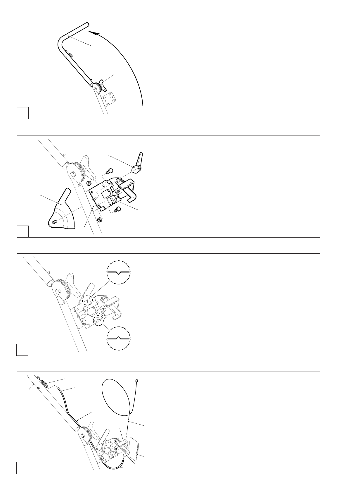
Sterngriff (1) lösen.
Griffrohr (2) in Pfeilrichtung nach oben klappen.
Sterngriff (1) festziehen.
HINWEIS:
Griffrohr je nach Körpergröße nach der Montage des Trennschleifers auf Arbeitshöhe einstellen.
Adaptersatz montieren
Aufnahmeblech (3) am Führungswagen (4), wie im Bild gezeigt, plazieren.
Schrauben und Muttern montieren (siehe Bild). Muttern vorerst
nicht anziehen.
Exzenterblech (5) mit Schnellspannhebel (6) montieren.
HINWEIS:
Durch Ziehen am Schnellspannhebel wird die Schraubwirkung
aufgehoben. Es kann durch „Nachfassen“ des Hebels gespannt werden.
4
C
D
12
11
13
Aufnahmeblech ausrichten, dazu die Einkerbungen in Übereinstimmung bringen.
Jetzt Muttern, siehe Bild B, fest anziehen.
Seilzug (7), wie im Bild dargestellt, durch den Bügel des
Adapters (8), die Druckfeder (9), die Gasbetätigung (10) und
durch die Bowdenzughülle (11) einfädeln.
Seilzugende durch den Gashebel (12) fädeln und am Seilende
ziehen, bis das Seil vollständig eingefädelt und die Bowdenzughülle (11) in der Aufnahme des Gashebels (12) sitzt.
8
7
9
Bowdenzughülle in die Aufnahme (13) am Griffrohr drücken.
HINWEIS:
Klemmschraube am Gashebel (12) nur leicht anziehen, um zu
verhindern, dass das Seil wieder herausrutscht. Die korrekte
Einstellung des Gashebels erfolgt bei der Montage des Trennschleifers (siehe „Trennschleifer montieren”).
1011
2

E
F
16
14
15
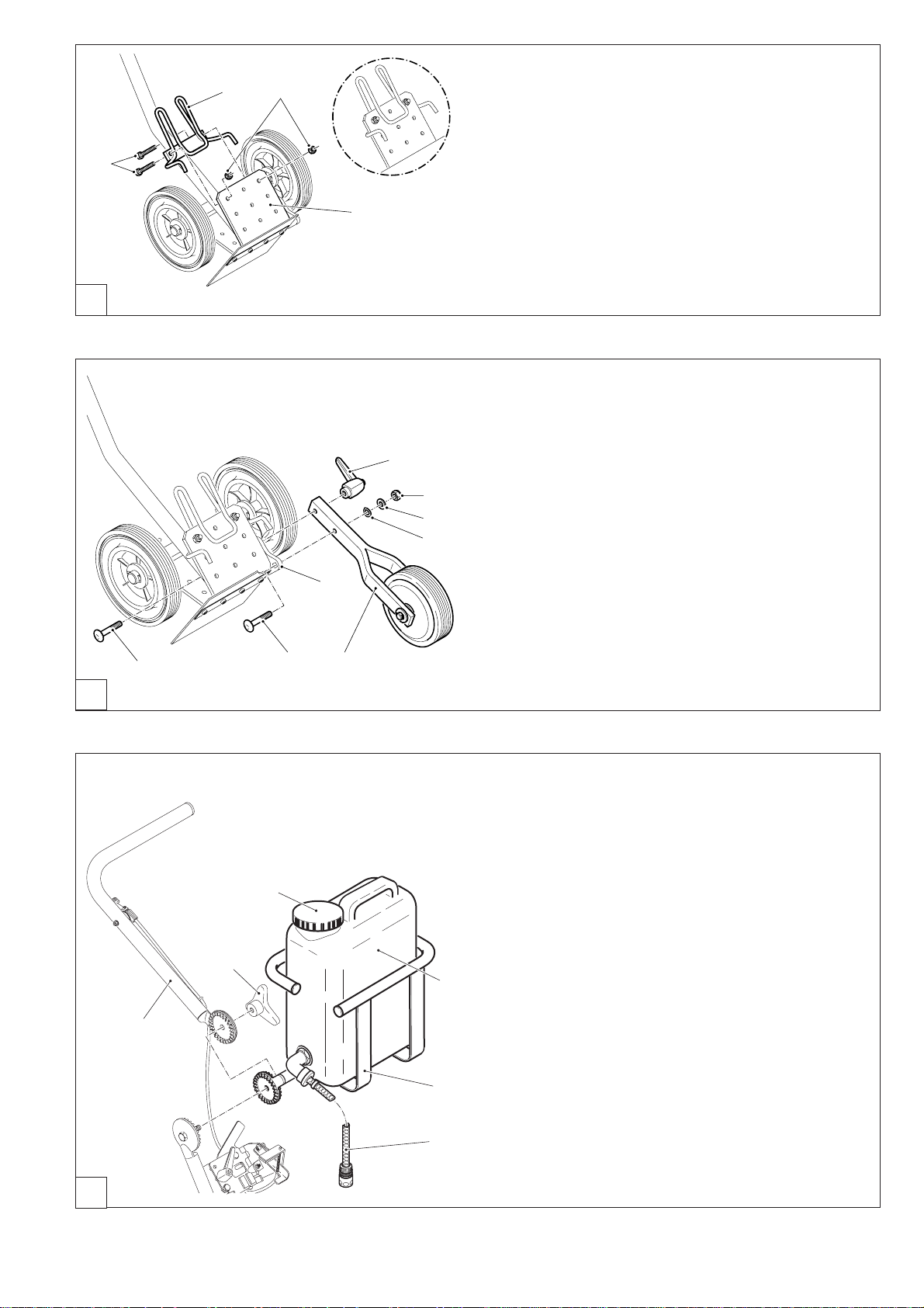
Klemmbügel (14) von unten (siehe Kreis) gegen die Aufnahmeplatte (17) mit Schrauben (16) montieren.
Muttern (15) aufschrauben und fest anziehen.
17
Führungsrad montieren
Schraube (1) durch die Vierkantbohrung am Führungswagen
7
6
5
4
2
8
1
3
(2) drücken (Vierkant der Schraube zum Vierkant der Bohrung
ausrichten).
Führungsrad (3), Federscheibe (4), Unterlegscheibe (5) und
Mutter (6) montieren.
Mutter (6) so anziehen, dass sich das Führungsrad am Führungswagen verdrehen läßt.
Zweite Schraube (8) durch die Langlochbohrung am Führungswagen und die Bohrung am Führungsrad führen.
Schnellspannhebel (7) aufschrauben.
HINWEIS:
Durch Ziehen am Schnellspannhebel wird die Schraubwirkung
aufgehoben. Es kann durch „Nachfassen“ des Hebels gespannt werden.
G
Wassertank montieren
Sterngriff (1) abschrauben und Griffrohr (2) abnehmen.
Tankhalter (3) und Griffrohr (2) mit Sterngriff montieren (siehe
Bild).
5
1
2
6
Wassertank (4) in den Tankhalter (3) stellen.
Anschlussschlauch (6) wird nach der Montage des Trenn-
schleifers seitlich am Trennschleifer vorbeigeführt und auf
das Kupplungsteil des Wassersets aufgesteckt.
HINWEIS:
4
Tankhalter (3) so ausrichten, dass der Wassertank beim
Arbeiten mit dem Führungswagen gerade steht.
HINWEIS:
Vor dem Befüllen des Wassertanks Anschlussschlauch (6)
vom Kupplungsteil des Wassersets am Trennschleifer tren-
3
nen. Wassertank aus Tankhalter nehmen, Deckel (5) abschrauben und den Wassertank mit sauberem Wasser füllen.
Verunreinigungen dürfen nicht in den Tank gelangen, da die
Berieselungsdüsen verstopfen können!
3

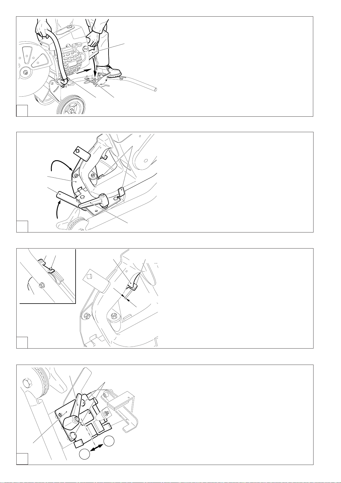
Trennschleifer montieren
H
2
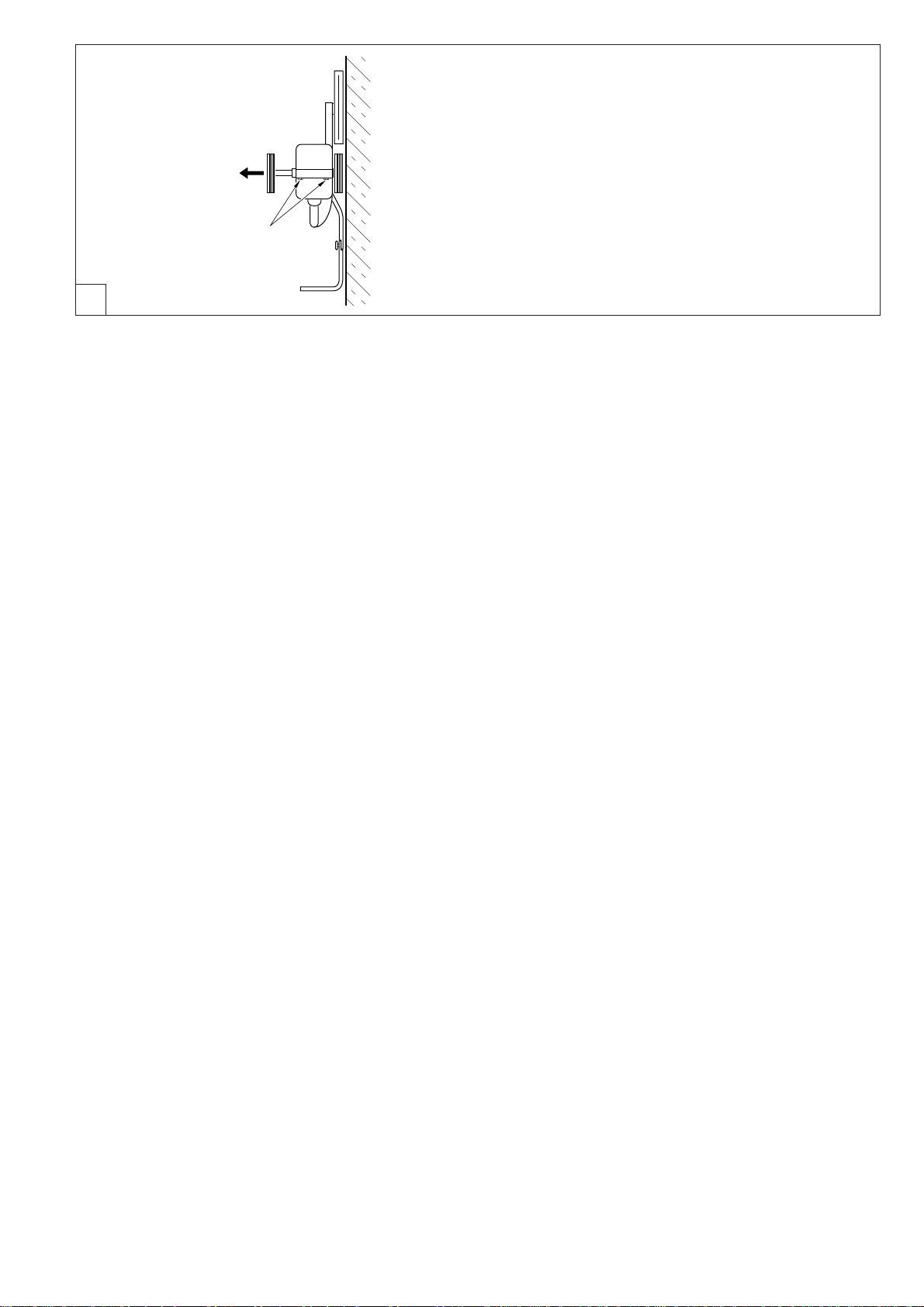
Führungswagen mit dem Griffrohr auf den Boden setzen.
Mit einem Fuß fest auf das Griffrohr treten.
Trennschleifer wie im Bild gezeigt festhalten und am Klemm-
bügel (1) auf beiden Seiten einhaken und bis zum Anschlag
nach hinten ziehen, dabei den Handschutz (2) zum Aufnahmeblech (3) schwenken.
1 3
4
Trennschleifer zwischen die beiden Aufnahmen (4) auf das
Aufnahmeblech drücken.
I
5
Feststellbügel (5) herumklappen (I) und mit dem Exzenterblech (6) sichern (II).
Exzenterblech mit dem Schnellspannhebel (7) verriegeln.
6
K
II
I
2
1
7
4 5
Gashebel einstellen
Gashebel (1) bis zum Anschlag zurückdrehen (parallel zum
Griffrohr).
Schraube (2) am Gashebel lösen.
3
2 - 3 mm
Seilende (3) anfassen und ziehen, bis der Abstand der Gasbetätigung (5) zum Gashebel am Trennschleifer (4) ca. 2 - 3 mm
beträgt.
Seil mit der Schraube (2) klemmen.
J
3
2
B
1
A
Gerade Schnittführung einstellen
Zieht der Führungswagen beim Schneiden mit dem Trennschleifer aus der geraden Schnittmarkierung nach links oder
rechts, kann eine Korrektur durch das Verschieben des Aufnahmeblechs (1) bewirkt werden.
Muttern an den Schrauben (2) lösen.
Schnellspannhebel (3) lösen.
Ein Verschieben des Aufnahmeblechs (1) in Richtung A be-
wirkt eine Schnittkorrektur nach links.
Ein Verschieben des Aufnahmeblechs (1) in Richtung B be-
wirkt eine Schnittkorrektur nach rechts.
4
schematische Darstellung
L
Räder verstellen
Der Radstand am Führungswagen läßt sich je nach Bedarf
einstellen. Um Schnitte sehr dicht an Hindernissen (z. B.
Bordsteinen, Mauern, Wänden u. s. w.) ausführen zu können,
Trennschleifer mit der Trennvorrichtung in Außenposition (siehe Betriebsanweisung des Trennschleifers) auf den Führungswagen montieren.
Schrauben (1) der Achsbefestigung lösen und Radachse ganz
1
nach links drücken.
Schrauben (1) fest anziehen.
5
Guide trolley control shaft
A
2
1
6
5
3
Loosen star handle (1).
Fold control shaft (2) upwards in the direction of the arrow.
Tighten star handle (1).
NOTE:
Depending on body size, adjust control shaft to working height
after mounting the power cut.
Mounting the adapter set
Place support plate (3) on guide trolley (4) as shown in illustration.
Fit the screws and nuts (see illustration), do not tighten nuts
for the moment.
Fit eccentric plate (5) with quick-action lever (6).
NOTE:
Pulling the quick-action lever cancels out the screw effect. It
can be tightened up by pulling the lever again.
B
C
D
12
11
4
Adjust support plate, aligning notches.
Now tighten nuts firmly, as shown in figure B.
Thread cable (7), as shown in picture, through the adapter
bracket (8), the compression spring (9), the gas operating device (10) and the Bowden cable sleeve (11).
Thread cable end through the gas lever (12) and pull on the
13
8
7
9
1011
cable end until the cable has been completely threaded through
and the Bowden cable sleeve (11) is resting in the support of
the gas lever (12).
Press Bowden cable sleeve into the support (13) on the control shaft.
NOTE:
Only tighten the clamping screw on the gas lever (12) slightly
to prevent the cable slipping out again. The gas lever is set
correctly when the power cut is mounted (see “Mounting the
power cut”).
6
E
F
16
14
15
Mount the clamp bracket (14) from underneath (see circled
diagram) against the support plate (17) using screws (16).
Fit nuts (15) and tighten firmly.
17
Mounting the guide wheel
Push screw (1) through the rectangular hole on the guide trol-
7
6
5
4
2
8
1
3
ley (2) (align the sides of the screw with the sides of the hole).
Mount guide wheel (3), compression washer (4), washer (5)
and nut (6).
Tighten nut (6) so that the guide wheel can be turned on the
guide trolley.
Push second screw (8) through the long hole on the guide
trolley and the hole on the guide wheel.
Tighten quick-action lever (7).
NOTE:
Pulling the quick-action lever cancels out the screw effect. It
can be tightened up by pulling the lever again.
G
Mounting the water tank
Unscrew the star handle (1) and remove control shaft (2).
Mount tank holder (3) and control shaft (2) with star handle
(see picture).
5
1
2
6
Put the water tank (4) in the tank holder (3).
When the Power Cut is assembled the hose (6) will go along
the side of the Power Cut and attach to the water set coupling.
NOTE:
Adjust the tank holder (3) so that the water tank is flush with
4
the guide trolley when working.
NOTE:
Before filling the water tank, detach the hose (6) from the water
set coupling and take the water tank out of the tank holder,
unscrew cap (5) and fill with clean water. Do not allow dirt to
3
get into the tank, as it could block the sprinkler nozzles.
7
Mounting the power cut
H
2
Place the guide trolley with the control shaft onto the floor.
Place one foot firmly on the control shaft.
Hold the power cut firmly as shown in the picture and hook on
the clamp bracket (1) on both sides; pull backwards as far as
it will go, swivelling the hand protector device (2) over the support plate (3).
1 3
4
Press the power cut between the two supports (4) onto the
support plate.
I
5
Fold out (I) the holding brackets (5) and secure (II) using the
eccentric plate (6).
Lock the eccentric plate in place using the quick-action lever
(7).
6
II
I
2
1
7
4 5
Setting the gas lever
Turn the gas lever (1) back as far as it will go (parallel to the
control shaft).
Loosen screw (2) on gas lever.
3
2 - 3 mm
Take hold of cable end (3) and pull until the distance between
the gas operating device (5) and the gas lever on the power
cut (4) is about 2-3 mm.
Clamp cable with screw (2).
J
3
2
Adjusting the cutting line
If the guide trolley pulls to the left or right of the straight cutting
line when you are cutting with the power cut, this can be corrected by pushing aside the support plate (1).
Loosen the nuts on the screws (2).
Loosen the quick-action lever (3).
Pushing the support plate (1) in the direction A corrects cut-
ting to the left.
1
B
Pushing the support plate (1) in the direction B corrects cutting to the right.
A
K
8

schematic diagram
L
Adjusting the wheels
The wheel spacing on the guide trolley may be adjusted if
necessary. To be able to cut very closely to obstacles (e.g.
kerbstones, masonry, walls, etc.), mount the power cut with
the cutting device in the outer position (see operating instructions for the power cut) on the guide trolley.
Loose screws (1) of the axle fixing and push wheel axle right
over to the left.
1
Tighten screws (1) firmly.
9

Tube-poignée du chariot
A
B
2
1
6
5
3
Desserrer la poignée en étoile (1).
Basculer le tube poignée (2) vers le haut dans le sens de la
flèche.
Serrer la poignée en étoile (1)
NOTA :
Régler la hauteur du tube-poignée à la taille de l’opérateur
après le montage de la découpeuse.
Montage du kit d’adaptation
Placer comme indiqué la tôle-support (3) sur le chariot de
guidage (4).
Monter les vis et les écrous (voir figure). Ne pas serrer les
écrous pour le moment.
Monter la tôle excentrique (5) avec le levier de serrage rapide
(6).
NOTA :
L’effet du vissage est annulé si l’on tire sur le levier de serrage
rapide. «Jouer» sur le levier pour serrer.
4
C
D
12
11
13
Ajuster la tôle-support en faisant coïncider les rainures.
Serrer fermement les écrous. Voir la figure B.
Enfiler le câble (7) comme indiqué sur la figure dans l’arceau
de l’adaptateur (8), le ressort de pression (9), la commande
des gaz (10) et le câble Bowden (11).
Enfiler l’extrémité du câble dans la manette des gaz (12) et
tirer sur l’extrémité du câble jusqu’à ce que celui-ci soit
entièrement enfilé et que le câble Bowden (11) ait pénétré
dans la manette des gaz (12).
8
7
9
1011
Appuyer le câble Bowden dans la fixation (13) sur le tubepoignée.
NOTA : Ne serrer que légèrement la vis de serrage sur la
manette des gaz (12) pour éviter que le câble ne ressorte. Le
réglage précis de la manette des gaz interviendra au moment
du montage de la découpeuse (voir «Montage de la
découpeuse»).
10
 Loading...