

Page 1
T
Model No.
Description
ECHNICAL INFORMATION
DS4010, DS4011/ DS5000
Drills 13mm (1/2")/ 16mm (5/8'')
PRODUCT
P 1/ 8
CONCEPT AND MAIN APPLICATIONS
These three drills are redesigned version of models 6013B, 6013BR, 6016BR
with the same high performance as the current models.
Their main features and benefits are:
Non-skid elastomer covering main handle area for good looking impression
and sure and comfortable grip
Full 360 degree rotatable D-handle with 24 positive stops
for multi-position operation
Switch type is the main notable specification difference between
these three models:
DS4010
Trigger type, without reverse function, with variable speed control
DS4011, DS5000
Rocker type, with reverse function, without variable speed control
DS4010 is also available without Drill chuck as model DS4010M.
Specification
DS4010
Voltage (V) Cycle (Hz)
110
120
220
230
240
DS4011, DS5000
110
120
220
230
240
Current (A)
7.2
6.5
3.6
3.4
3.3
7.2
6.5
3.6
3.4
3.3
50/ 60
50/ 60
50/ 60
50/ 60
50/ 60
50/ 60
50/ 60
50/ 60
50/ 60
50/ 60
Continuous Rating (W)
Input
750
--750
750
750
750
--750
750
750
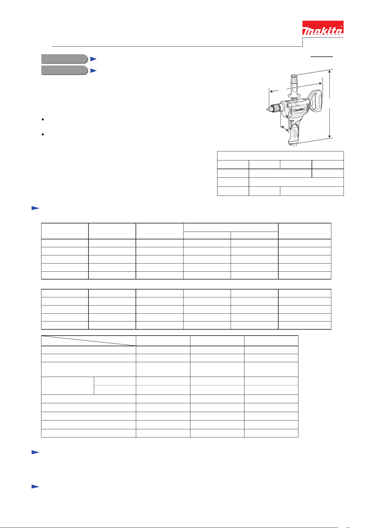
Model No.
Length (L)
Width (W)
Height (H)
L
W
Dimensions: mm (")
DS4010 DS4011 DS5000
391 (15-3/8)
Output
380
380
380
380
380
350
350
350
350
350
340 (13-3/8)
83 (3-1/4)
Max. Output (W)
348 (13-3/4)
401 (15-3/4)
540
650
650
650
650
550
550
550
550
550
H
Specification
No load speed: minDrill chuck type
Chuck capacity: mm (")
Capacities: mm (")
Reverse function
Variable speed control by trigger
Double insulation
Power supply cord
Net weight
*1 2.0m (6.6ft) for Brazil, Australia *2 Weight according to EPTA-Procedure 01/2003, with Side grip
*2: kg (lbs)
Model No.
1= rpm
Steel
Wood
*1: m (ft)
DS4010 DS4011 DS5000
0 - 600 600 600
Keyed Keyed Keyed
2 - 13
(1/16 - 1/2)
13 (1/2)
36 (1-7/16)
No
Yes
Yes
2.5 (8.2) 2.5 (8.2) 2.5 (8.2)
2.8 (6.2) 2.8 (6.3) 3.0 (6.6)
2 - 13
(1/16 - 1/2)
13 (1/2)
36 (1-7/16)
Yes
No
Yes
3 - 16
(1/8 - 5/8)
16 (5/8)
36 (1-7/16)
Yes
No
Yes
Standard equipment
Chuck key S-13 ........... 1 (for DS4010, DS4011)
Chuck key S-16 ........... 1 (for DS5000)
Note: The standard equipment for the tool shown above may vary by country.
Side grip ...................... 1
Plastic carrying case .... 1 (for DS4011, if requested)
Optional accessories
Depth gauge
Keyless Drill chuck set (for DS4010, DS4011)
Keyed drill chuck set (for DS4010, DS4011)
Bits
Hole saws
Wrench 9 (for Hole saw)
Angle attachment
Wrench 17 (for Angle attachment)
Page 2
P 2/ 8
Repair
CAUTION: Repair the machine in accordance with “Instruction manual” or “Safety instructions”.
[1] NECESSARY REPAIRING TOOLS
Code No. Description Use for
1R139 Drill chuck extractor Removing / Assembling Drill chuck
1R223 Torque wrench shaft 20-90 N.m Removing / Assembling Drill chuck
1R224 Ratchet head 12.7 Attaching to 1R223 Torque wrench shaft 20-90 N.m
1R269 Bearing extractor Removing Ball bearings
1R291 Retaining ring S and R pliers Removing / Assembling Retaining rings
1R298 Hex. bar 10 with square socket Removing / Assembling Drill chuck
1R340 Bearing retainer wrench Removing / Assembling Bearing retainer
781024-2 Wrench 43 Removing broken Drill chuck for DS4010 and DS4011
781007-2 Wrench 14 Removing broken Drill chuck for DS5000
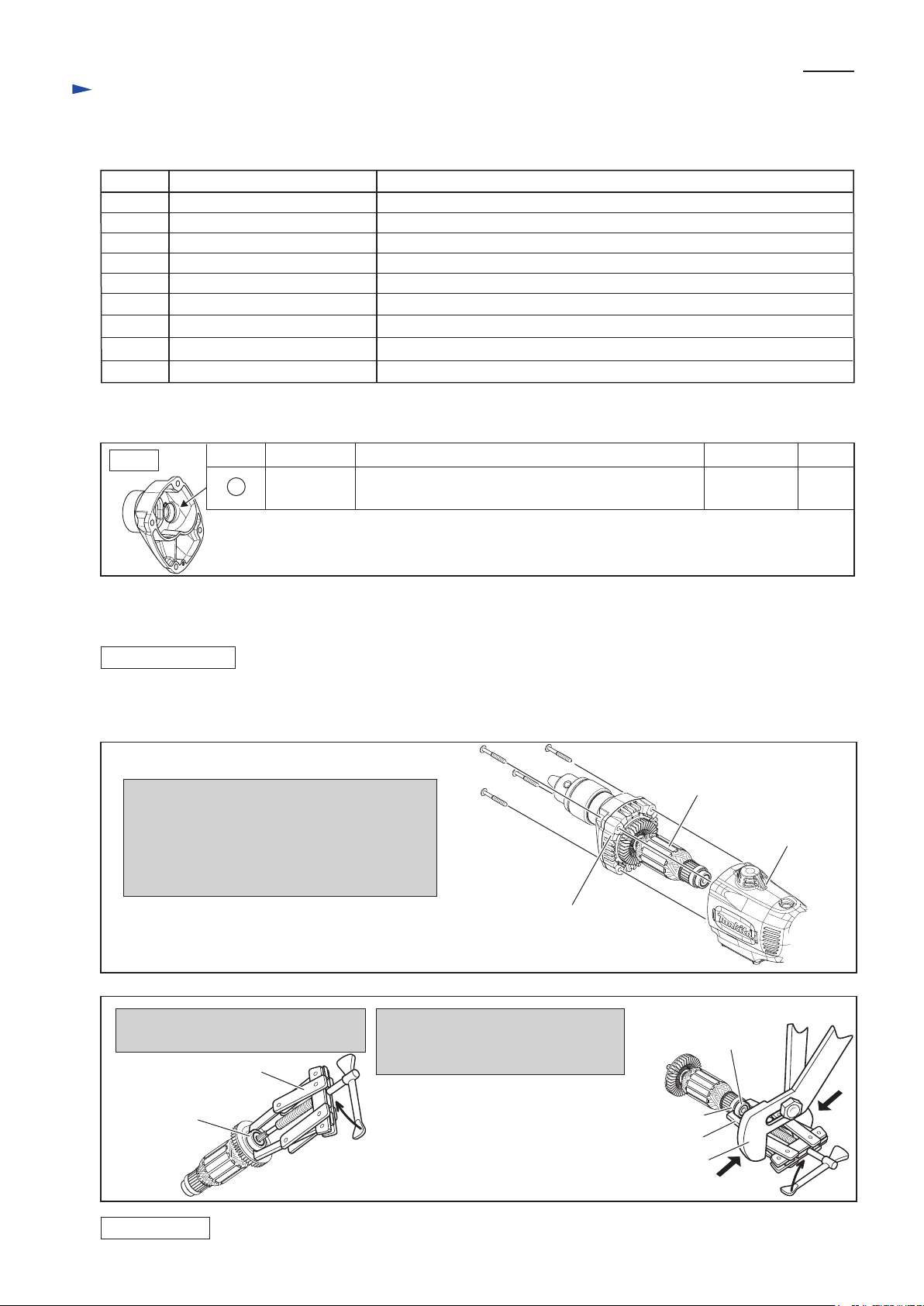
[2] LUBRICATIONS
Apply the following lubricant to the portion to protect parts and product from unusual abrasion.
Fig. 1
Item No.
8
Description Lubricant
Gear housing
complete
Gear room where Spur gear 47 and Gear complete 7-41
engage with Armature’ gear (Refer to Fig. 8.)
Portion to lubricate
Makita
grease N No.2
Amount
10g
[3] DISASSEMBLY/ASSEMBLY
[3]-1. Armature
DISASSEMBLING
(1) Remove Armature ass’y as illustrated in Fig. 2.
(2) Disassemble Armature ass’y as illustrated in Fig. 3.
Fig. 2
1. Remove Carbon brushes.
2. Remove four 5x40 Tapping screws and then
pull off Armature together with Gear housing
cover complete from Motor housing complete.
3. Remove Armature ass’y from Gear cover
housing complete.
Fig. 3
1. Remove Ball bearing 608LLB from
Armature drive end with 1R269.
1R269
Ball bearing 608LLB
2. Remove Ball bearing 608LLB from
the commutator end of Armature
with 1R269 and Water pump pliers.
Note: Be sure to firmly grasp
the jaws of 1R269 with
Water pump pliers because
the space between
Insulation washer and Ball
bearing 608LLB is very tight.
5x40 Tapping
screw (4pcs.)
Gear cover housing complete
Insulation washer
Water pump pliers
Armature ass’y
Motor housing
complete
Ball bearing 608LLB
1R269
ASSEMBLING
Take the disassembling step in reverse.
Page 3
Repair
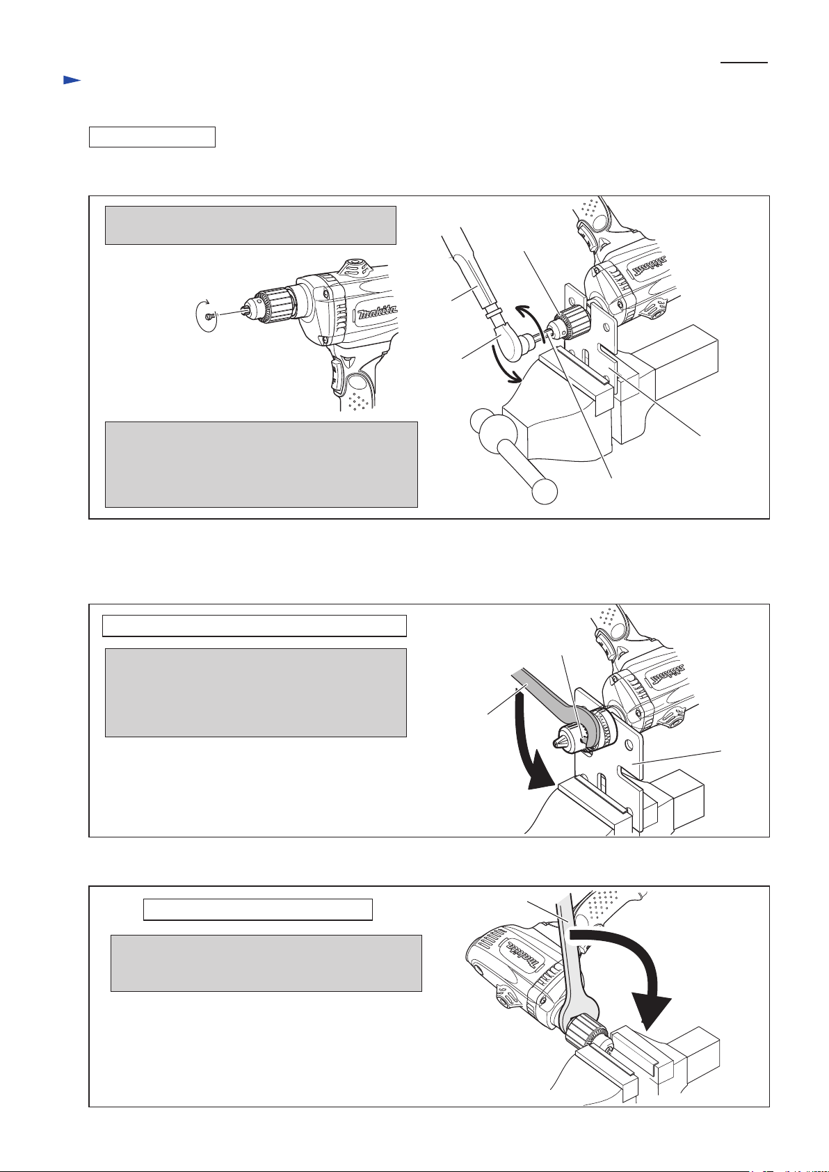
[3]-2. Drill chuck, Gear, Spindle
DISASSEMBLING
(1) Remove Drill chuck as illustrated in Fig. 4.
Fig. 4
1. Loosen the jaws of Drill chuck and then remove
M6x22 Flat head screw by turning it clockwise.
M6x22 Flat head screw
Note: It has left-hand thread.
P 3/ 8
Drill chuck
1R223
1R224
2. Fit the flats of Spindle to the notch of 1R139
and then hold 1R139 in vise.
3. Attach 1R224 and 1R298 to 1R223 and then secure
1R298 with Drill chuck.
4. Turn 1R223 counterclockwise.
(1A) When Drill chuck is broken, 1R298 can not be secured with the Drill chuck.
Therefore, separate the drill chuck from Spindle as illustrated in Fig. 5 or 6
after removing M6x22 Flat head screw.
Fig. 5
Removing Drill chuck S13 for DS4010 and DS4011
1. Fit the flats of Spindle to the notch of 1R139
and then hold 1R139 in vise.
2. Fit the pin of 781024-2 into a hole of Drill chuck,
and turn 781024-2 counterclockwise as illustrated
right.
Hole of Drill chuck
781024-2
1R139
1R298
1R139
Fig. 6
Removing Drill chuck S16 for DS5000
1. Hold Drill chuck in vise.
2. Fit the flats of 781007-2 to those of Spindle and
turn 781007-2 counterclockwise as illustrated right.
781007-2
Page 4

Repair
[3] DISASSEMBLY/ASSEMBLY
[3]-2. Drill chuck, Gear, Spindle
DISASSEMBLING
(2) Gears can be removed as illustrated in Figs. 7 and 8.
Fig. 7
P 4/ 8
1. Hold Switch cover handle in vise.
remove Bearing retainer 22-36 by
turning it clockwise with 1R340.
Note: Use Cushion to protect
Switch cover handle in vise.
1R340
Bearing
retainer
22-36
Note:
It has a
left-hand
thread.
Fig. 8
4. Remove Retaining ring S-14
with 1R291 from Spindle.
Retaining ring S-14
Switch cover
handle
2. Separate Motor housing complete
from Gear housing cover complete
by removing four 5x70 Tapping
screws.
5x70 Tapping screw
(4pcs.)
Gear housing
cover complete
Motor housing complete
5. Strike Gear housing complete to
remove Gears as illustrated below.
Gear complete 7-41 with
Fiber washer 6
Ball bearing 626LLB
Key 5
Spur gear 47
3. After pulling off Armature,
separate Gear housing cover
complete and Gasket from
Gear housing complete.
Do not lose Pin 3.
Gear housing complete
Gasket
Pin 3
Gear housing cover complete
6. Remove Spindle together
with Ball bearing 6202LLB
from Gear housing complete.
Spindle
(3) Remove Ball bearings on Spindle and Gear complete 7-41 with 1R269 as illustrated in Fig. 9.
Fig. 9
Remove Ball bearing
6202LLB from Spindle.
1R269
Ball bearing 6202LLB
Spindle
Remove Ball bearing
626LLB from Gear
complete 7-41.
Ball bearing 626LLB
Gear complete 7-41
Ring 15
1R269
Spindle
Ball bearing
6202LLB
Page 5

Repair
[3] DISASSEMBLY/ASSEMBLY
[3]-2. Gear, Spindle
(1) Assemble Gear section as illustrated in Figs. 10 and 11.
Fig. 10
P 5/ 8
1. Assemble Ball bearing 626LLB
to Gear housing complete.
Meanwhile, assemble Ball bearing
6202LLB to Spindle, then set them
in place of Gear housing complete.
Ball bearing
626LLB
Spindle
Ball bearing
6202LLB
Fig. 9
4. Set Pin 3 in place to assemble Gasket
and Gear housing cover complete
precisely to Gear housing complete
in the next step.
Key 5
2. Fit Key 5 to Spindle’s groove.
And assemble Ring 15 and Spur
gear 47 to Spindle.
Secure their parts to Spindle with
Retaining ring S-14.
Spur gear 47
Ring 15
Retaining
ring S-14
Key 5
5. Align the holes of Gasket and those of Gear housing cover complete
and insert Pin 3 through Gasket into Gear housing complete.
3. Insert Gear complete 7-41 into Ball
bearing 626LLB with Spur gear 47
engaged.
Do not forget to assemble Fiber
washer 6 to the Gear complete 7-41.
Fiber washer 6
Gear complete 7-41
Pin 3
Gasket
Pin 3
Gear housing complete
(3) Take the disassembling step in reverse. Refer to Figs. 5 and 4.
Note: 1. Turn 1R340 counterclockwise for setting Bearing retainer 22-36 in place.
2. Preset the fastening torque of 1R223 to 68.6 - 78.4 N.m (700 - 800 Kgf.cm) and turn Drill chuck clockwise to
Spindle using 1R223 with 1R224, 1R139, 1R298 and vise.
Gear housing
cover complete
[3]-3. Leaf spring
ASSEMBLING
Two Leaf springs have to be set in place of Handle set (L) without dropping. See Fig. 10.
Fig. 10
Handle set (L)
Leaf spring
Page 6

Circuit diagram
Fig.D-1
P 6/ 8
Model DS4010 without reverse switch,
with variable speed control
Color index of lead wires' sheath
Black
Brown
Blue
Switch
(Noise suppressor
is built in.)
This Lead wire is black
for some countries.
Field viewed from
Armature fan side
This Lead wire is white
for some countries.
Line filter
Fig.D-1A
Models DS4011 and DS5000 with reverse switch,
without variable speed control
Color index of lead wires' sheath
Black
Purple
Orange
Blue
White
Field viewed from
Armature Fan side
Switch viewed from
Trigger side
4
Noise
suppressor
Terminal
block
Line filter
1
5
6
1
2
3
Resistor
2
3
Page 7

Wiring diagram
Fig.D-2
P 7/ 8
Model DS4010 without reverse switch,
with variable speed control
Motor Housing
viewed from Armature fan side
To Switch terminals
M1 and M2
Pass Field lead wires
(black) through the
hole to connect
them to Switch.
Switch handle cover set (L)
Pass field lead wires
(black) between Boss
and rib of Hole.
Put Line filter between
Ribs.
Line filter
Switch
Hole for
storing
Chuck key
Boss
Rib
Power supply cord
Pass the Lead wires
of Power supply cord
through Line filter.
Fig.D-2A
Models DS4011 and DS5000 with reverse switch,
without variable speed control
Motor Housing viewed
from Armature fan side
Pass Field lead wires
(blue, orange, black)
through this hole.
Pass Field lead wires
(black, purple, white)
through this hole.
to Switch
Page 8

Wiring diagram (cont.)
Fig.D-3A
Put Line filter here
P 8/ 8
Models DS4011 and DS5000 with reverse switch,
without variable speed control
Switch handle cover set (L)
Hole for storing Chuck key
Pass field lead wires between Boss
and Hole for storing Chuck key
Line filter
Coil Field lead wires
(orange) and (purple)
to Line filter one time.
Resistor
Noise
supperssor
Viewed from Switch cover handle (R) side
1. Connect Field lead wire (white) to
Switch terminal No. 6 and Field lead
wire (blue) to Switch terminal No.3
from Switch trigger side.
Boss
Connect Field lead wires
(white), (purple), (orange),
(blue) as illustrated in
Fig. D-SP.
Rib
Do not to put the folowing Lead wires
Terminal
block
Rib
on the Ribs and Terminal block.
* Field lead wires (black)
* Noise suppressor’s lead wire (white)
* Lead wires (brown), (blue)
of Power supply cord
Viewed from Switch cover handle (L) side
Screw head
Switch terminal end
Field lead
wire (purple)
Field lead wire
(white)
2. Inflect their Insulated connectors of
the Field lead wires until they touch
Screw heads.
Insulated terminal
3. Insulated connectors of Field lead
wires (purple) and (orange) have to
be located inside of Switch terminal
end.
Field lead wire
(blue)
Screw head
Switch terminal end
Field lead wire
(orange)
 Loading...