

Page 1
EN
Cordless Slide Compound
Miter Saw
INSTRUCTION MANUAL 11
PL
HU
SK
CS
UK
RO
DE
Ukośnica akumulatorowa INSTRUKCJA OBSŁUGI 25
Vezeték nélküli csúszókocsis
gérvágó fűrész
Akumulátorová posuvná
pokosová píla na
kombinované rezanie
Akumulátorová radiální
pokosová pila
Акумуляторна пересувна
комбінована пила для
різання під кутом
Ferăstrău pentru tăieri oblice
combinate, fără cablu
Akku-Kapp. und
Gehrungssäge
DLS714
HASZNÁLATI KÉZIKÖNYV 41
NÁVOD NA OBSLUHU 56
NÁVOD K OBSLUZE 71
ІНСТРУКЦІЯ З
ЕКСПЛУАТАЦІЇ
MANUAL DE INSTRUCŢIUNI 101
BETRIEBSANLEITUNG 116
85
Page 2
1
4
6
7
5
3
2
Fig.1
8
10
12
17
18
16
19
15
9
11
13
20
12
14
21
22
Fig.2
Fig.3
22
1
25
24
1
1
Fig.4
2
23
Page 3
2
3
1
2
1
Fig.5
Fig.6
Fig.7
Fig.9
1
2
1
1
Fig.10
2
Fig.11
1
2
1
Fig.8
1
1
Fig.12
3
Page 4
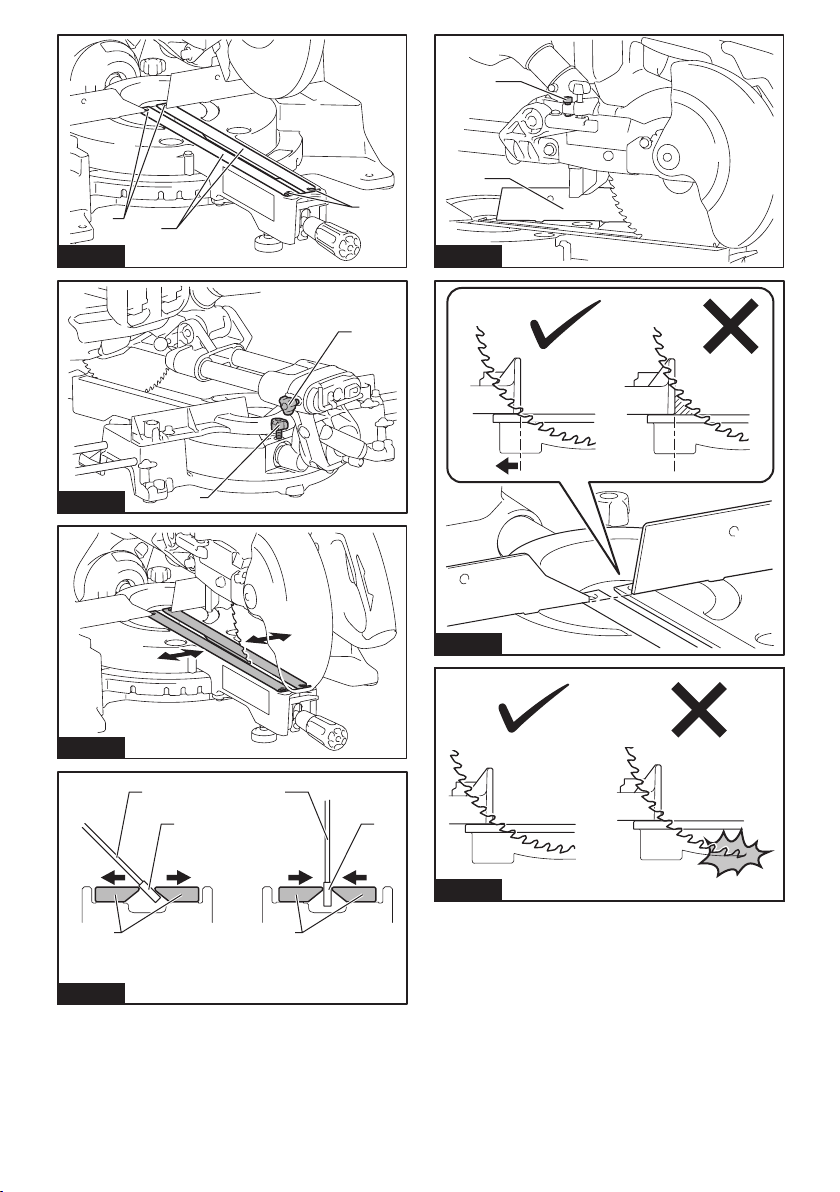
Fig.13
45
1
2
2
1
2
Fig.17
1
Fig.14
Fig.15
Fig.16
1 1
3
1
Fig.18
2 2
Fig.19
3
4
Page 5
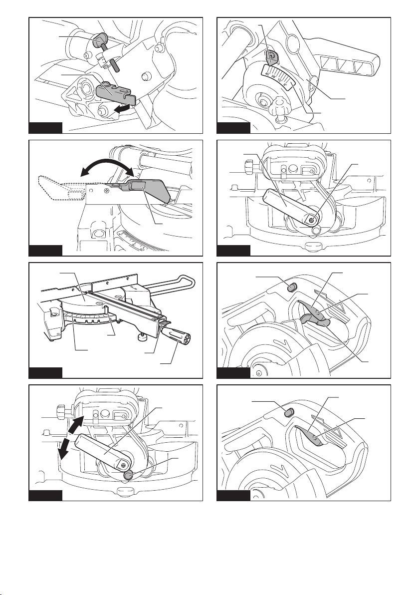
Fig.20
1
1
2
3
2
Fig.24
1
2
1
Fig.21
Fig.22
Fig.23
Fig.25
1
2
3
4
5
1
2
3
Fig.26
1
Fig.27
2
4
1
2
3
5
Page 6
1
2
3
Fig.28
Fig.29
3
Fig.30
4
1
1
2
2
1
Fig.32
2
Fig.33
1
4
Fig.34
2
4
6
2
5
1
3
5
Fig.31
1
3
2
6
1
Fig.35
2
4
5
3
6
Page 7
1
2
3
3
1
Fig.36
Fig.37
Fig.38
4
1
3
1
6
2
2
5
Fig.40
1
Fig.41
Fig.42
2
2
2
4
1
Fig.39
2
8
7
8
7
4
5
6
1
3
Fig.43
7
Page 8
(a)
(b)
(b)
(a)
1
(c)
(a)
(d)
(b)
(b)
(a)
(b)
2
(a)
Fig.44
Fig.45
123
Fig.46
Fig.48
2
3
1
4
Fig.49
(a) (b) (c) (d)
12
Fig.50
1
2
Fig.47
(a) (b) (c) (d)
12
3
4
5
Fig.51
8
Page 9
1
Fig.53
Fig.54
Fig.55
3
1
2
Fig.57
1
Fig.58
Fig.59
1
2
2
3
1
5
4
3
Fig.56
1
2
Fig.60
9
1
2
3
Page 10
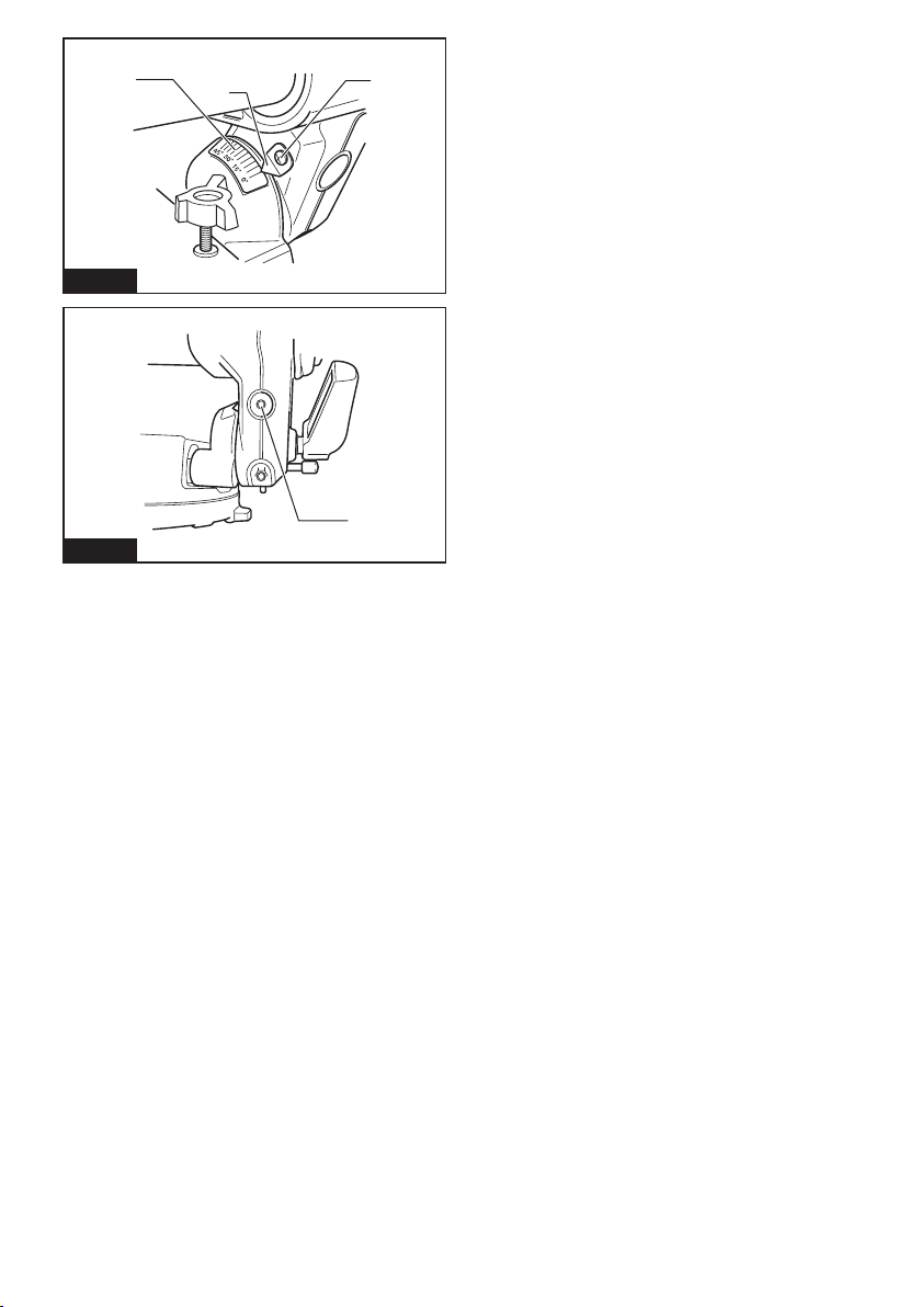
Fig.61
Fig.62
1
2
3
1
10
Page 11
ENGLISH (Original instructions)
Cd
Li-ion
SPECIFICATIONS
Model: DLS714
Blade diameter 190 mm
Blade body thickness 1.3 mm - 2.0 mm
Hole (arbor) diameter (country specic) 20 mm or 15.88 mm
Max. miter angle Left 47°, Right 57°
Max. bevel angle Left 45°, Right 5°
No load speed 5,700 min
Dimensions (L x W x H) 655 mm x 430 mm x 445 mm
Rated voltage D.C.36 V
Battery cartridge BL1815N, BL1820, BL1820B BL1830, BL1830B, BL1840,
Net weight 13.0 kg 13.5 kg
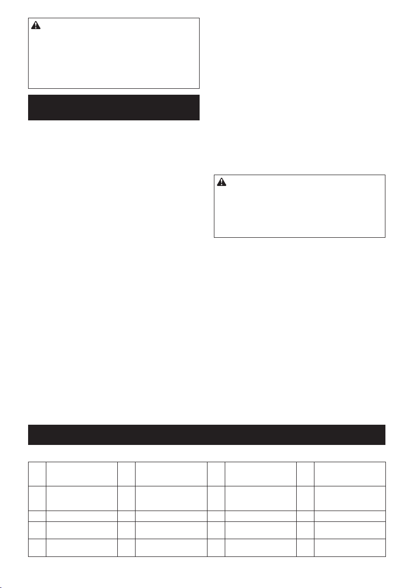
Cutting capacities (H x W) with blade 190 mm in diameter
Miter angle Bevel angle
45° (left) 0° 5° (right)
0° 40 mm x 300 mm 52 mm x 300 mm 40 mm x 300 mm
45 mm x 265 mm (NOTE 1) 60 mm x 265 mm (NOTE 1) –
45° (left and right) 40 mm x 212 mm 52 mm x 212 mm –
45 mm x 185 mm (NOTE 2) 60 mm x 185 mm (NOTE 2) –
57° (right) – 52 mm x 163 mm –
– 60 mm x 145 mm (NOTE 3) –
1. Max. Cutting capacity when using a wood facing 20 mm thickness
2. Max. Cutting capacity when using a wood facing 15 mm thickness
3. Max. Cutting capacity when using a wood facing 10 mm thickness
• Due to our continuing program of research and development, the specications herein are subject to change
without notice.
• Specications and battery cartridge may differ from country to country.
• Weight, with battery cartridge, according to EPTA-Procedure 01/2003
Symbols
The following show the symbols used for the equipment. Be sure that you understand their meaning before
use.
Read instruction manual.
To avoid injury from ying debris, keep
holding the saw head down, after making
cuts, until the blade has come to a complete stop.
When performing slide cut, rst pull carriage fully and press down handle, then
push carriage toward the guide fence.
Do not place hand or ngers close to the
blade.
Always set SUB-FENCE to left position
when performing left bevel cuts. Failure to
do so may cause serious injury to operator.
Ni-MH
Intended use
The tool is intended for accurate straight and miter
cutting in wood. With appropriate saw blades, aluminum
can also be sawed.
Do not use the saw to cut other than wood, aluminum or
similar materials.
Only for EU countries
Do not dispose of electric equipment or
battery pack together with household waste
material!
In observance of the European Directives,
on Waste Electric and Electronic
Equipment and Batteries and Accumulators
and Waste Batteries and Accumulators
and their implementation in accordance
with national laws, electric equipment and
batteries and battery pack(s) that have
reached the end of their life must be collected separately and returned to an environmentally compatible recycling facility.
-1
BL1840B, BL1850, BL1850B,
BL1860B
11 ENGLISH
Page 12

Noise
The typical A-weighted noise level determined according to EN61029:
Sound pressure level (LpA) : 88 dB(A)
Sound power level (LWA) : 97 dB (A)
Uncertainty (K) : 3 dB(A)
WARNING: Wear ear protection.
Vibration
The vibration total value (tri-axial vector sum) determined according to EN61029:
Vibration emission (ah) : 2.5 m/s2 or less
Uncertainty (K) : 1.5 m/s
NOTE: The declared vibration emission value has
been measured in accordance with the standard test
method and may be used for comparing one tool with
another.
NOTE: The declared vibration emission value
may also be used in a preliminary assessment of
exposure.
2
WARNING: The vibration emission during actual
use of the power tool can differ from the declared
emission value depending on the ways in which the
tool is used.
WARNING: Be sure to identify safety measures
to protect the operator that are based on an estimation of exposure in the actual conditions of use (taking
account of all parts of the operating cycle such as
the times when the tool is switched off and when it is
running idle in addition to the trigger time).
EC Declaration of Conformity
For European countries only
Makita declares that the following Machine(s):
Designation of Machine: Cordless Slide Compound
Miter Saw
Model No./ Type: DLS714
Conforms to the following European Directives:
2006/42/EC
They are manufactured in accordance with the following
standard or standardized documents: EN61029
The technical le in accordance with 2006/42/EC is
available from:
Makita, Jan-Baptist Vinkstraat 2, 3070, Belgium
16.1.2015
Yasushi Fukaya
Director
Makita, Jan-Baptist Vinkstraat 2, 3070, Belgium
General power tool safety warnings
WARNING: Read all safety warnings and
all instructions. Failure to follow the warnings and
instructions may result in electric shock, re and/or
serious injury.
Save all warnings and instructions for future reference.
The term "power tool" in the warnings refers to your
mains-operated (corded) power tool or battery-operated
(cordless) power tool.
Cordless miter saw safety warnings
1. Keep hands out of path of saw blade. Avoid
contact with any coasting blade. It can still
cause severe injury.
2. Check the saw blade carefully for cracks or
deformation before operation.
Replace damaged blades immediately.
3. Replace the kerf board when worn.
4. Use only saw blades specied by the manufac-
turer which conform to EN847-1.
5. Do not use saw blades manufactured from
high speed steel.
6. Wear eye protection.
7. Wear hearing protection to reduce the risk of
hearing loss.
8. Wear gloves for handling saw blade (saw
blades shall be carried in a holder wherever
practicable) and rough material.
9. Connect miter saws to a dust collecting device
when sawing.
10. Select saw blades in relation to the material to
be cut.
11. Always secure all moving portions before carrying the tool. When lifting or carrying the tool,
do not use the guard as a carrying handle.
12. Do not operate saw without guards in place.
Check blade guard for proper closing before
each use. Do not operate saw if blade guard
does not move freely and close instantly.
Never clamp or tie the blade guard into the
open position.
13. Keep the oor area free of loose material e.g.
chips and cut-offs.
14. Use only saw blades that are marked with a
maximum speed equal to or higher than the no
load speed marked on the tool.
15. When the tool is tted with a laser or LED, do
not replace the laser or LED with a different
type. Ask an authorized service center for repair.
16. Never remove any cut-offs or other parts of the
workpiece from the cutting area whilst the tool
is running with an unguarded saw blade.
17. Do not perform any operation freehand. The
workpiece must be secured rmly against the
turn base and guide fence with the vise during all
operations. Never use your hand to secure the
workpiece.
18. Ensure that the tool is stable before each cut.
19. Fix the tool to a work bench, if needed.
20. Support long workpieces with appropriate
additional supports.
21. Never cut so small workpiece which cannot be
securely held by the vise. Improperly held work-
piece may cause kickback and serious personal
injury.
22. Never reach around saw blade.
12 ENGLISH
Page 13

23. Turn off tool and wait for saw blade to stop
before moving workpiece or changing
settings.
24. Disconnect the plug from the power source
and/or the battery pack from the power tool
before changing blade or servicing.
25. Stopper pin which locks the cutter head down
is for carrying and storage purposes only and
not for any cutting operations.
26. Do not use the tool in the presence of ammable liquids or gases. The electrical operation of
the tool could create an explosion and re when
exposed to ammable liquids or gases.
27. Use only anges specied for this tool.
28. Be careful not to damage the arbor, anges
(especially the installing surface) or bolt.
Damage to these parts could result in blade
breakage.
29. Make sure that the turn base is properly
secured so it will not move during operation.
30. For your safety, remove the chips, small
pieces, etc. from the table top before
operation.
31. Avoid cutting nails. Inspect for and remove all
nails from the workpiece before operation.
32. Make sure the shaft lock is released before the
switch is turned on.
33. Be sure that the blade does not contact the
turn base in the lowest position.
34. Hold the handle rmly. Be aware that the saw
moves up or down slightly during start-up and
stopping.
35. Make sure the blade is not contacting the
workpiece before the switch is turned on.
36. Before using the tool on an actual workpiece,
let it run for a while. Watch for vibration or
wobbling that could indicate poor installation
or a poorly balanced blade.
37. Wait until the blade attains full speed before
cutting.
38. Stop operation immediately if you notice anything abnormal.
39. Do not attempt to lock the trigger in the on
position.
40. Be alert at all times, especially during repetitive, monotonous operations. Do not be lulled
into a false sense of security. Blades are
extremely unforgiving.
41. Always use accessories recommended in this
manual. Use of improper accessories such as
abrasive wheels may cause an injury.
42. Take care when slotting.
43. Some dust created from operation contains
chemicals known to cause cancer, birth
defects or other reproductive harm. Some
examples of these chemicals are:
• lead from lead-based-painted material
and,
• arsenic and chromium from chemical-
ly-treated lumber.
Your risk from these exposures varies,
depending on how often you do this type
of work. To reduce your exposure to these
chemicals: work in a well ventilated area and
work with approved safety equipment, such as
those dust masks that are specially designed
to lter out microscopic particles.
44. To reduce the emitted noise, always be sure
that the blade is sharp and clean.
45. The operator is adequately trained in the use,
adjustment and operation of the machine.
SAVE THESE INSTRUCTIONS.
WARNING: DO NOT let comfort or familiarity
with product (gained from repeated use) replace
strict adherence to safety rules for the subject
product. MISUSE or failure to follow the safety
rules stated in this instruction manual may cause
serious personal injury.
Important safety instructions for
battery cartridge
1.
Before using battery cartridge, read all instructions and cautionary markings on (1) battery charger, (2) battery, and (3) product using battery.
2. Do not disassemble battery cartridge.
3. If operating time has become excessively
shorter, stop operating immediately. It may
result in a risk of overheating, possible burns
and even an explosion.
4. If electrolyte gets into your eyes, rinse them
out with clear water and seek medical attention right away. It may result in loss of your
eyesight.
5. Do not short the battery cartridge:
(1) Do not touch the terminals with any con-
ductive material.
(2) Avoid storing battery cartridge in a con-
tainer with other metal objects such as
nails, coins, etc.
(3) Do not expose battery cartridge to water
or rain.
A battery short can cause a large current
ow, overheating, possible burns and even a
breakdown.
6. Do not store the tool and battery cartridge in
locations where the temperature may reach or
exceed 50 °C (122 °F).
7. Do not incinerate the battery cartridge even if
it is severely damaged or is completely worn
out. The battery cartridge can explode in a re.
8. Be careful not to drop or strike battery.
9. Do not use a damaged battery.
10. The contained lithium-ion batteries are subject
to the Dangerous Goods Legislation requirements.
For commercial transports e.g. by third parties,
forwarding agents, special requirement on packaging and labeling must be observed.
For preparation of the item being shipped, consulting an expert for hazardous material is required.
Please also observe possibly more detailed
national regulations.
13 ENGLISH
Page 14
Tape or mask off open contacts and pack up the
battery in such a manner that it cannot move
around in the packaging.
11. Follow your local regulations relating to dis-
posal of battery.
SAVE THESE INSTRUCTIONS.
CAUTION: Only use genuine Makita batteries.
Use of non-genuine Makita batteries, or batteries that
have been altered, may result in the battery bursting
causing res, personal injury and damage. It will
also void the Makita warranty for the Makita tool and
charger.
Tips for maintaining maximum
battery life
1. Charge the battery cartridge before completely
discharged. Always stop tool operation and
charge the battery cartridge when you notice
less tool power.
2. Never recharge a fully charged battery cartridge. Overcharging shortens the battery
service life.
3. Charge the battery cartridge with room temperature at 10 °C - 40 °C (50 °F - 104 °F). Let
a hot battery cartridge cool down before
charging it.
4. Charge the battery cartridge if you do not use
it for a long period (more than six months).
PARTS DESCRIPTION
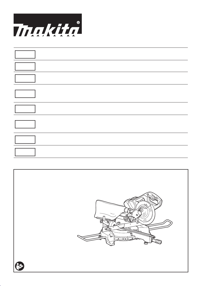
► Fig.1
1 Lock-off button 2 Switch trigger 3 Blade case 4 Adjusting screw (for
5 Adjusting bolt (for maxi-
mum cutting capacity)
9 Blade guard 10 Vertical vice 11 Guide fence 12 Holder
13 Lock lever (for turn base) 14 Grip (for turn base) 15 Adjusting bolt (for turn
17 Pointer (for miter angle) 18 Turn base - - - -
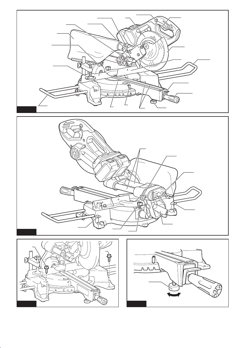
► Fig.2
19 Slide pole (upper) 20 Thumb screw (for lock-
23 Lever (for bevel angle
adjustment)
6 Stopper arm 7 Dust bag 8 Bevel scale
base)
ing upper slide pole)
24 Slide pole (lower) 25 Thumb screw (for lock-
21 Hex wrench 22 Clamp screw (for locking
ing lower slide pole)
lower limit position)
16 Kerf board
holder)
- -
INSTALLATION
Bench mounting
WARNING: Ensure that the tool does not
move on the supporting surface. Movement of the
miter saw on the supporting surface while cutting may
result in loss of control and serious personal injury.
1. Fix the base to a level and stable surface, screw-
ing with two bolts. This helps to prevent from tipping and
possible injury.
► Fig.3: 1. Bolt
2. Turn the adjusting bolt clockwise or counterclockwise so that it comes into a contact with the oor sur-
face to keep the tool stable.
► Fig.4: 1. Adjusting bolt
FUNCTIONAL
DESCRIPTION
WARNING: Always be sure that the tool is
switched off and the battery cartridge is removed
before adjusting or checking the functions on
the tool. Failure to switch off and remove the battery
cartridge may result in serious personal injury from
accidental start-up.
Installing or removing battery
cartridge
CAUTION: Always switch off the tool before
installing or removing of the battery cartridge.
CAUTION: Hold the tool and the battery car-
tridge rmly when installing or removing battery
cartridge. Failure to hold the tool and the battery
cartridge rmly may cause them to slip off your hands
and result in damage to the tool and battery cartridge
and a personal injury.
14 ENGLISH
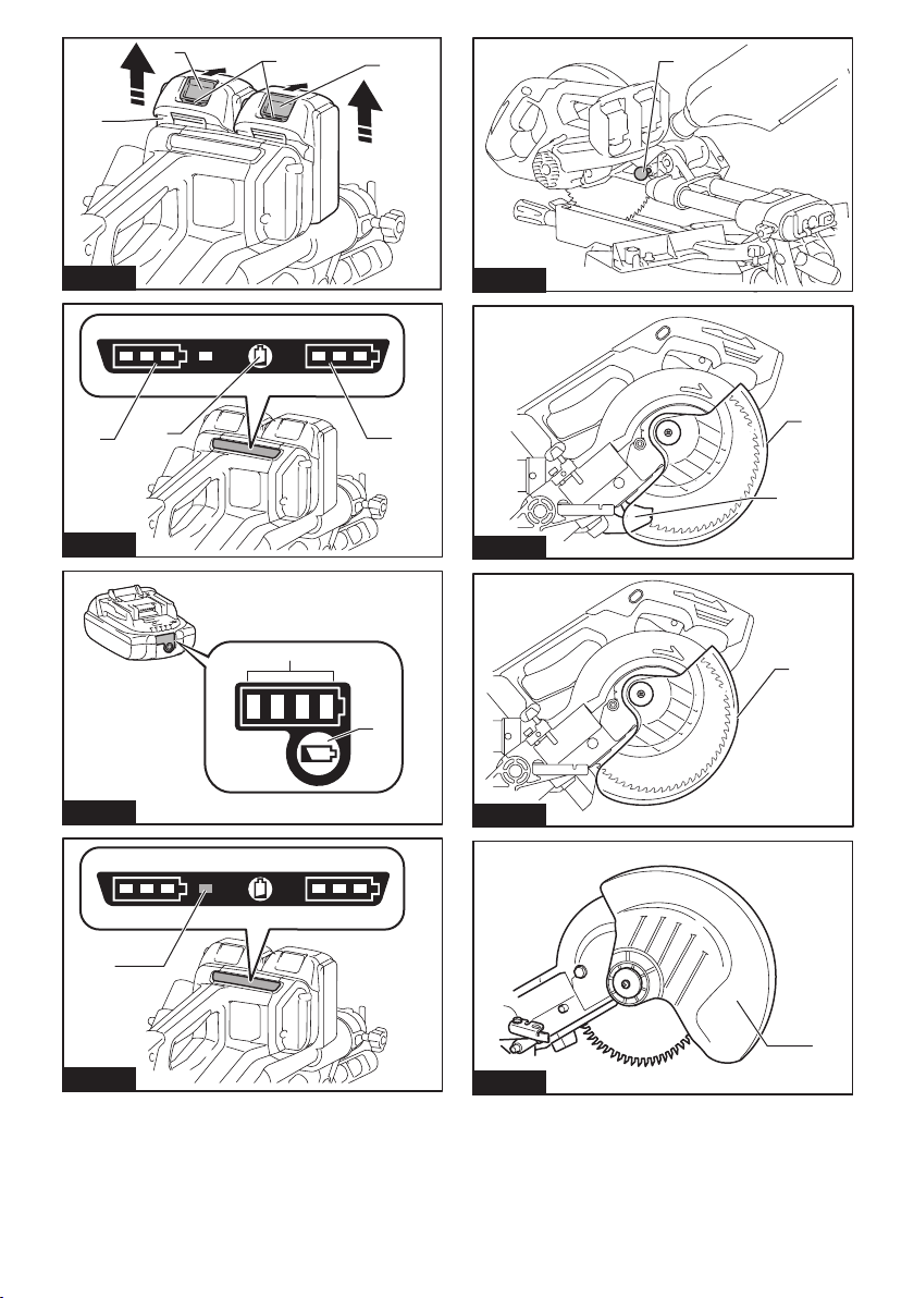
Page 15
► Fig.5: 1. Red indicator 2. Button 3. Battery cartridge
To remove the battery cartridge, slide it from the tool
while sliding the button on the front of the cartridge.
To install the battery cartridge, align the tongue on the
battery cartridge with the groove in the housing and slip
it into place. Insert it all the way until it locks in place
with a little click. If you can see the red indicator on the
upper side of the button, it is not locked completely.
CAUTION: Always install the battery cartridge
fully until the red indicator cannot be seen. If not,
it may accidentally fall out of the tool, causing injury to
you or someone around you.
CAUTION: Do not install the battery cartridge
forcibly. If the cartridge does not slide in easily, it is
not being inserted correctly.
NOTE: The tool does not work with only one battery
cartridge.
Tool / battery protection system
The tool is equipped with a tool/battery protection system. This system automatically cuts off power to the
motor to extend tool and battery life. The tool will automatically stop during operation if the tool or battery is
placed under one of the following conditions:
Overload protection
When the tool is operated in a manner that causes it to
draw an abnormally high current, the tool automatically
stops without any indication. In this situation, turn the
tool off and stop the application that caused the tool to
become overloaded. Then turn the tool on to restart.
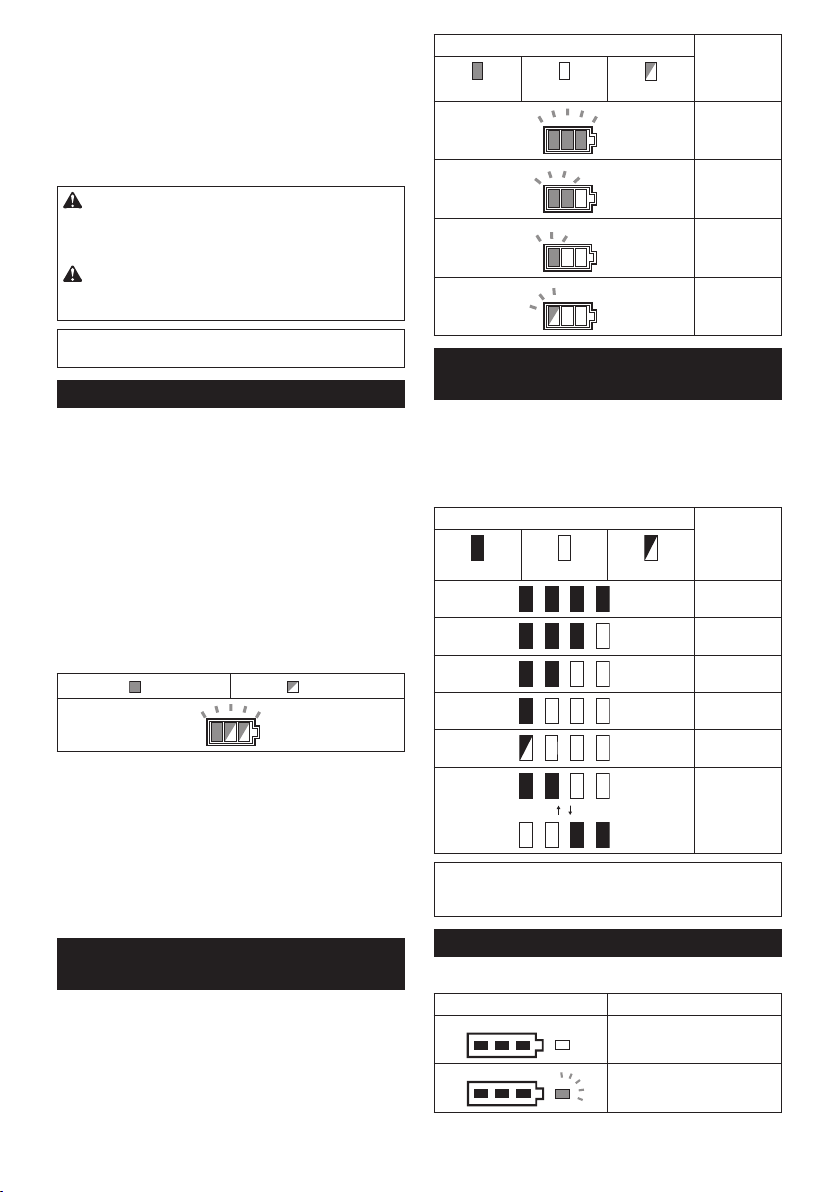
Overheat protection
on Blinking
Battery indicator status Remaining
On
Off
Blinking
battery
capacity
50% to 100%
20% to 50%
0% to 20%
Charge the
battery
Indicating the remaining battery
capacity
Only for battery cartridges with the indicator
► Fig.7: 1. Indicator lamps 2. Check button
Press the check button on the battery cartridge to indi-
cate the remaining battery capacity. The indicator lamps
light up for few seconds.
Indicator lamps Remaining
Lighted Off Blinking
capacity
75% to 100%
50% to 75%
25% to 50%
0% to 25%
When the tool is overheated, the tool stops automatically, and the battery indicator blink about 60 seconds.
In this situation, let the tool cool down before turning the
tool on again.
Overdischarge protection
When the battery capacity becomes low, the tool stops
automatically. If the product does not operate even
when the switches are operated, remove the batteries
from the tool and charge the batteries.
Indicating the remaining battery
capacity
► Fig.6: 1. Battery indicator 2. Check button
Press the check button to indicate the remaining battery
capacities. The battery indicators correspond to each
battery.
NOTE: Depending on the conditions of use and the
ambient temperature, the indication may differ slightly
from the actual capacity.
Automatic speed change function
► Fig.8: 1. Mode indicator
Mode indicator status Operation mode
High speed mode
High torque mode
15 ENGLISH
Charge the
battery.
The battery
may have
malfunctioned.
Page 16

This tool has "high speed mode" and "high torque
mode". It automatically changes operation mode
depending on the work load. When mode indicator
lights up during operation, the tool is in high torque
mode.
Stopper pin
CAUTION: Always hold the handle when
releasing the stopper pin. Otherwise the handle
springs up and it may result in personal injury.
To release the stopper pin, keep applying a slight
downward pressure on the handle and then pulling the
stopper pin.
► Fig.9: 1. Stopper pin
Blade guard
WARNING: Never defeat or remove the blade
guard or the spring which attaches to the guard.
An exposed blade as a result of defeated guarding
may result in serious personal injury during operation.
WARNING: Never use the tool if the blade
guard or spring are damaged, faulty or removed.
Operation of the tool with a damaged, faulty or
removed guard may result in serious personal injury.
CAUTION: Always maintain the blade guard in
good condition for safe operation. Stop the operation
immediately if there are any irregularity of the blade
guard. Check to assure spring loaded return action
of guard.
For tools with blade guard release lever
► Fig.10: 1. Blade guard A 2. Blade guard B
When lowering the handle, the blade guard A rises
automatically. The blade guard B rises as it contacts a
workpiece. The guards are spring loaded so it returns to
its original position when the cut is completed and the
handle is raised.
For tools without blade guard release lever
► Fig.11: 1. Blade guard
When lowering the handle, the blade guard raises
automatically. The guard is spring loaded so it returns to
its original position when the cut is completed and the
handle is raised.
Cleaning
► Fig.12: 1. Blade guard
If the transparent blade guard becomes dirty, or saw-
dust adheres to it in such a way that the blade and/or
workpiece is no longer easily visible, remove the battery
cartridge and clean the guard carefully with a damp
cloth. Do not use solvents or any petroleum-based
cleaners on the plastic guard because this may cause
damage to the guard.
For cleaning, raise the blade guard by referring to
"Installing or removing saw blade".
After cleaning, make sure to return the blade and center
cover and tighten the hex socket bolt.
1. Make sure that the tool is switched off and the
battery cartridges are removed.
2. Turn the hex socket bolt counterclockwise using
the supplied hex wrench with holding the center cover.
3. Raise the blade guard and center cover.
4. When cleaning is complete, return the center
cover and tighten the hex socket bolt by performing the
steps above in reverse.
WARNING: Do not remove spring holding
blade guard. If guard becomes damaged in course
of time or UV light exposure, contact a Makita service center for replacement. DO NOT DEFEAT OR
REMOVE GUARD.
Positioning kerf board
This tool is provided with the kerf boards in the turn
base to minimize tearing on the exit side of a cut. The
kerf boards are factory adjusted so that the saw blade
does not contact the kerf boards. Before use, adjust the
kerf boards as follows:
1. Make sure to remove the battery cartridge. Then,
loosen all the screws (2 each on left and right) securing
the kerf boards.
► Fig.13: 1. Kerf board 2. Screw
2. Re-tighten them only to the extent that the kerf
boards can still be easily moved by hand.
3. Lower the handle fully and push in the stopper pin
to lock the handle in the lowered position.
4. Loosen two clamp screws which secure the slide
poles.
► Fig.14: 1. Thumb screw
5. Pull the carriage toward you fully.
6. Adjust the kerf boards so that the kerf boards just
contact the sides of the blade teeth.
► Fig.15
► Fig.16: 1. Saw blade 2. Blade teeth 3. Kerf board
4. Left bevel cut 5. Straight cut
7. Tighten the front screws (do not tighten rmly).
8. Push the carriage toward the guide fence fully and
adjust the kerf boards so that the kerf boards just contact the sides of blade teeth.
9. Tighten the rear screws (do not tighten rmly).
10. After adjusting the kerf boards, release the stop-
per pin and raise the handle. Then tighten all the screws
securely.
NOTICE: After setting the bevel angle ensure
that the kerf boards are adjusted properly. Correct
adjustment of the kerf boards helps to provide proper
support of the workpiece and minimizing workpiece
tear out.
Maintaining maximum cutting
capacity
This tool is factory adjusted to provide the maximum
cutting capacity for a 190 mm saw blade.
When installing a new blade, always check the lower
limit position of the blade, and if necessary, adjust it as
follows:
16 ENGLISH
Page 17
1. Remove the battery cartridge. Then, push the carriage toward the guide fence fully and lower the handle
completely.
► Fig.17: 1. Adjusting bolt 2. Guide fence
2. Use the hex wrench to turn the adjusting bolt until
the saw blade comes slightly below the cross section of
the guide fence and the top surface of the turn base.
► Fig.18
3. Rotate the blade by hand while holding the handle
all the way down to be sure that the blade does not
contact any part of the lower base. Re-adjust slightly, if
necessary.
WARNING: After installing a new blade and
with the battery cartridge removed, always be
sure that the blade does not contact any part of
the lower base when the handle is lowered com-
pletely. If a blade makes contact with the base it may
cause kickback and result in serious personal injury.
► Fig.19
Stopper arm
The lower limit position of the blade can be easily
adjusted with the stopper arm. To adjust it, move the
stopper arm in the direction of the arrow as shown in
the gure. Turn the adjusting screw and press down the
handle fully to check the result.
► Fig.20: 1. Adjusting screw 2. Stopper arm
Sub-fence
Country specic
CAUTION: When performing left bevel cuts,
ip the sub-fence outward. Otherwise, it may con-
tact the blade or a part of the tool, and may result in
serious injury to the operator.
► Fig.21: 1. Sub-fence
This tool is equipped with the sub-fence. Usually posi-
tion the sub-fence inside. However, when performing
left bevel cuts, ip it outward.
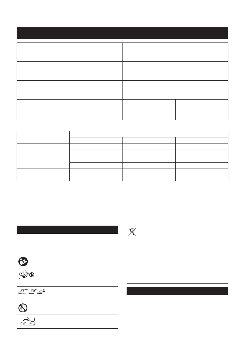
Adjusting the miter angle
► Fig.22: 1. Turn base 2. Pointer 3. Miter scale
4. Lock lever 5. Grip
1. Loosen the grip counterclockwise.
2. Press down and hold the lock lever, and adjust the
angle of the turn base. Use the pointer and the miter
scale as a guide.
3. Tighten the grip clockwise rmly.
CAUTION: After changing the miter angle,
always secure the turn base by tightening the grip
rmly.
NOTICE: When turning the turn base, be sure to
raise the handle fully.
Adjusting the bevel angle
To adjust the bevel angle, loosen the lever at the rear of
the tool counterclockwise.
► Fig.23: 1. Lever 2. Release button
To tilt the blade to the left, hold the handle and tilt the
carriage. Use the bevel scale and the pointer as a guide.
Then tighten the lever clockwise rmly to secure the arm.
► Fig.24: 1. Pointer 2. Bevel scale 3. Arm
To tilt the blade to the right, hold the handle and tilt the
carriage to the left slightly, and push the release button.
With the release button pressed, tilt the saw blade to
the right. Then tighten the lever.
CAUTION:
secure the arm by tightening the lever clockwise.
After changing the bevel angle, always
NOTICE: When tilting the saw blade be sure the
handle is fully raised.
NOTICE:
to position the kerf boards appropriately as
explained in the "Positioning kerf boards" section.
When changing bevel angles, be sure
Adjusting the lever position
If the lever does not provide full tightening in course of
time, change the position of the lever. The lever can be
repositioned at every 30° angle.
Loosen and remove the screw that secures the lever. Remove
the lever and install it again so that it points slightly above the
horizontal. Then, tighten the lever with the screw rmly.
► Fig.25: 1. Lever 2. Screw
Switch action
WARNING: Before installing the battery car-
tridge on the tool, always check to see that the
switch trigger actuates properly and returns to
the "OFF" position when released. Operating a tool
with a switch that does not actuate properly can lead
to loss of control and serious personal injury.
WARNING: Do not use a lock with a shank or
cable any smaller than 6.35 mm (1/4") in diameter.
A smaller shank or cable may not properly lock the
tool in the off position and unintentional operation
may occur resulting in serious personal injury.
WARNING:
ative switch trigger. Any tool with an inoperative switch
is HIGHLY DANGEROUS and must be repaired before
further usage or serious personal injury may occur.
WARNING: For your safety, this tool is equipped
with a lock-off button which prevents the tool from
unintended starting. NEVER use the tool if it runs
when you simply pull the switch trigger without
pressing the lock-off button. A switch in need of
repair may result in unintentional operation and seri-
ous personal injury. Return tool to a Makita service
center for proper repairs BEFORE further usage.
WARNING: NEVER defeat the lock-off button
by taping down or some other means. A switch with
a negated lock-off button may result in unintentional
operation and serious personal injury.
NEVER use tool without a fully oper-
17 ENGLISH
Page 18
NOTICE: Do not pull the switch trigger hard
without pressing in the lock-off button. This can
cause switch breakage.
For tools with blade guard release lever
To prevent the switch trigger from being accidentally
pulled, a lock-off button is provided. To start the tool,
push the blade guard release lever up, press in the
lock-off button and then pull the switch trigger. Release
the switch trigger to stop.
The lock-off button can be pressed from either right or
left.
A hole is provided in the switch trigger for insertion of a
padlock to lock the tool off.
► Fig.26: 1. Blade guard release lever 2. Switch trig-
ger 3. Lock-off button 4. Hole for padlock
For tools without blade guard release lever
To prevent the switch trigger from being accidentally
pulled, a lock-off button is provided. To start the tool,
press in the lock-off button and pull the switch trigger.
Release the switch trigger to stop.
The lock-off button can be pressed from either right or
left.
A hole is provided in the switch trigger for insertion of a
padlock to lock the tool off.
► Fig.27: 1. Lock-off button 2. Switch trigger 3. Hole
for padlock
ASSEMBLY
WARNING: Always be sure that the tool is
switched off and the battery cartridge is removed
before working on the tool. Failure to switch off and
remove the battery cartridge may result in serious
personal injury.
Hex wrench storage
The hex wrench is stored as shown in the gure. When
the hex wrench is needed it can be pulled out of the
wrench holder.
After using the hex wrench it can be stored by returning
it to the wrench holder.
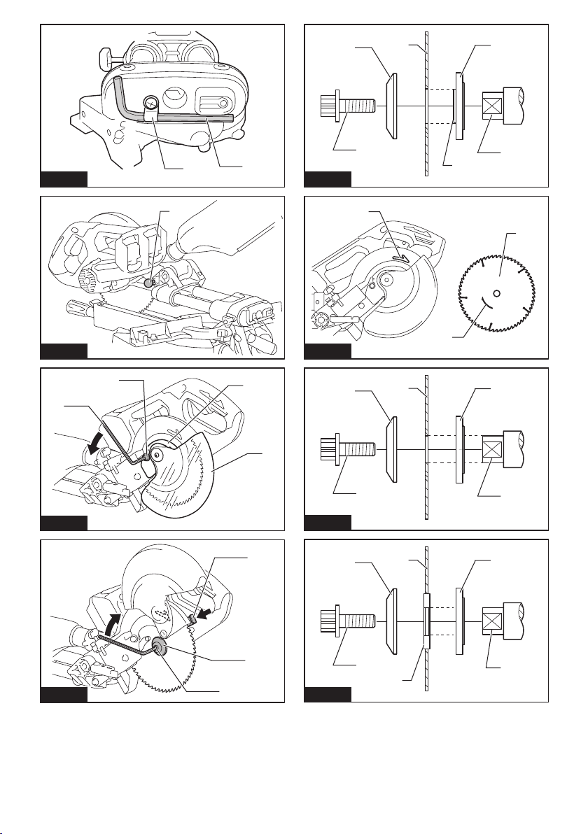
► Fig.28: 1. Wrench holder 2. Hex wrench
Installing or removing saw blade
WARNING: Always be sure that the tool is
switched off and the battery cartridge is removed
before installing or removing the blade. Accidental
start up of the tool may result in serious personal
injury.
CAUTION: Use only the Makita hex wrench
provided to install or remove the blade. Failure
to do so may result in overtightening or insufcient
tightening of the hex socket bolt. This could cause
an injury.
To remove the blade, perform the following steps:
1. Lock the handle in the raised position by pushing
in the stopper pin.
► Fig.29: 1. Stopper pin
2. Use the hex wrench to loosen the hex socket bolt
holding the center cover by turning it counterclockwise.
Then, raise the blade guard and center cover.
► Fig.30: 1. Center cover 2. Hex socket bolt 3. Hex
3.
wrench to loosen the hex socket bolt clockwise. Then remove
the hex socket bolt of the spindle, outer ange and blade.
► Fig.31: 1. Shaft lock 2. Hex socket bolt 3. Outer
4.
with its blade mounting part facing the blade. If the ange is
installed incorrectly the ange will rub against the machine.
► Fig.32: 1. Outer ange 2. Saw blade 3. Inner ange
To install the blade, perform the following steps:
1. Mount the blade carefully onto the inner ange.
Make sure that the direction of the arrow on the blade
matches the direction of the arrow on the blade case.
► Fig.33: 1. Saw blade 2. Arrow
2. Install the outer ange and hex socket bolt, and
then use the hex wrench to tighten the hex socket bolt
(left-handed) of the spindle securely counterclockwise
while pressing the shaft lock.
3. Return the blade guard and center cover to its
original position. Then tighten the hex socket bolt of the
center cover clockwise to secure the center cover.
4. Release the handle from the raised position by
pulling the stopper pin. Lower the handle to make sure
that the blade guard moves properly.
5. Make sure the shaft lock has released spindle
before making cut.
wrench 4. Blade guard
Press the shaft lock to lock the spindle and use the hex
ange
If the inner ange is removed, install it on the spindle
4. Hex socket bolt (left-handed) 5. Spindle
6. Blade mounting part
For tool with the inner ange for
15.88 mm hole-diameter saw blade
Country specic
Mount the inner ange with its recessed side facing
outward onto the mounting shaft and then place saw
blade (with the ring attached if needed), outer ange
and hex bolt.
For tool without the ring
► Fig.34: 1. Outer ange 2. Saw blade 3. Inner ange
For tool with the ring
► Fig.35: 1. Outer ange 2. Saw blade 3. Inner ange
blade onto the spindle, always be sure that the
correct ring for the blade's arbor hole you intend
to use is installed between the inner and the outer
anges. Use of the incorrect arbor hole ring may
result in the improper mounting of the blade causing
blade movement and severe vibration resulting in
possible loss of control during operation and in seri-
ous personal injury.
18 ENGLISH
4. Hex socket bolt (left-handed) 5. Spindle
4. Hex socket bolt (left-handed) 5. Ring
6. Spindle
WARNING: If the ring is needed to mount the
Page 19
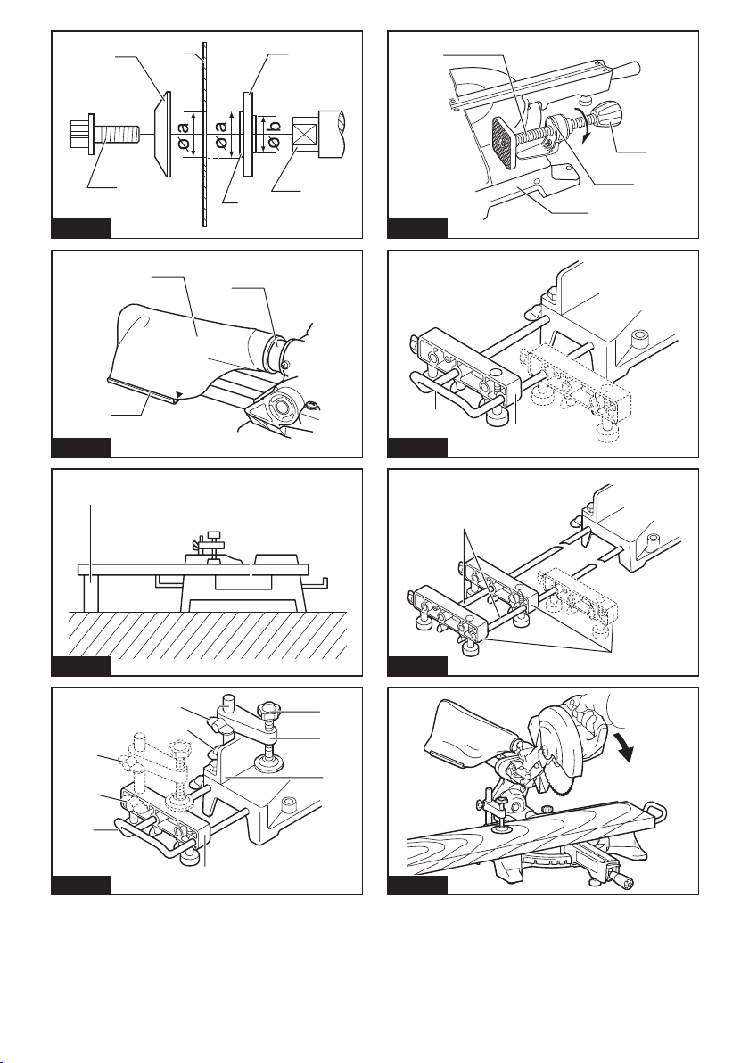
For tool with the inner ange for
other than 20 mm or 15.88 mm hole-
diameter saw blade
Country specic
The inner ange has a certain diameter of a blade
mounting part on one side of it and a different diameter
of blade mounting part on the other side. Choose a
correct side on which blade mounting part ts into the
saw blade hole perfectly.
► Fig.36: 1. Outer ange 2. Saw blade 3. Inner ange
4. Hex socket bolt (left-handed) 5. Spindle
6. Blade mounting part
CAUTION: Make sure that the blade mounting
part "a" on the inner ange that is positioned
outside ts into the saw blade hole "a" perfectly.
Mounting the blade on the wrong side can result in
the dangerous vibration.
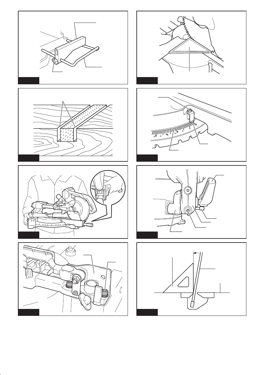
Dust bag
Optional accessory
The use of the dust bag makes cutting operations
cleaner and dust collection easier.
To attach the dust bag, t it onto the dust nozzle.
To attach the fastener, align the top end of the fastener
with the triangular mark on the dust bag.
When the dust bag is about half full, remove the dust
bag from the tool and pull the fastener out. Empty
the dust bag of its contents, tapping it lightly so as to
remove particles adhering to the insides which might
hamper further collection.
► Fig.37: 1. Dust bag 2. Dust nozzle 3. Fastener
NOTE: If you connect a vacuum cleaner to your saw,
cleaner operations can be performed.
Securing workpiece
WARNING: It is extremely important to always
secure the workpiece correctly with the proper
type of vise. Failure to do so may result in serious
personal injury and cause damage to the tool and/or
the workpiece.
WARNING: When cutting a workpiece that
is longer than the support base of the saw, support the entire length of the material beyond the
support base and at the same height to keep the
material level. Proper workpiece support helps to
avoid blade pinch and possible kickback which may
result in serious personal injury. Do not rely solely on
the vertical vise and/or horizontal vise to secure the
workpiece. Thin material tends to sag. Support work-
piece over its entire length to avoid blade pinch and
possible KICKBACK.
► Fig.38: 1. Support 2. Turn base
Vertical vise
WARNING: Secure the workpiece rmly
against the turn base and guide fence with the
vise during all operations. Otherwise the material
may move during the cutting operation, cause damage to the blade, and be thrown which may result in
loss of control and serious personal injury.
Install the vertical vise on either the left or right side of
the guide fence or the holder assembly (optional accessory). Insert the vise rod into the hole in the guide fence
or the holder assembly and tighten the lower screw to
secure the vise rod.
► Fig.39: 1. Vise arm 2. Vise rod 3. Guide fence
4. Holder 5. Holder assembly 6. Vise knob
7. Lower screw 8. Upper screw
Position the vise arm according to the thickness and
shape of the workpiece and secure the vise arm by
tightening the upper screw. If the upper screw contacts
the guide fence, install the upper screw on the opposite
side of vise arm. Make sure that no part of the tool
contacts the vise when lowering the handle fully and
pulling or pushing the carriage all the way. If some part
contacts the vise, re-position the vise.
Press the workpiece at against the guide fence and the
turn base. Position the workpiece at the desired cutting
position and secure it rmly by tightening the vise knob.
Horizontal vise
Optional accessory
WARNING: Grip the workpiece only when the
indicator is at the topmost position. Failure to do
so may result in insufcient securing of the workpiece.
This may cause the workpiece to be thrown, cause
damage to the blade or cause the loss of control,
which may result in personal injury.
► Fig.40: 1. Vise knob 2. Indicator 3. Vise shaft
4. Base
The horizontal vise can be installed on the left side of
the base.
By turning the vise knob counterclockwise, the screw
is released and the vise shaft can be moved rapidly in
and out. By turning the vise knob clockwise, the screw
remains secured.
To grip the workpiece, turn the vise knob gently clockwise until the indicator reaches its topmost position,
then fasten securely. If the vise knob is forced in or
pulled out while being turned clockwise, the indicator
may stop at an angle. In this case, turn the vise knob
back counterclockwise until the screw is released, and
then turn it again gently clockwise.
The maximum capacity of the horizontal vise is 120 mm
width.
19 ENGLISH
Page 20
Holders and holder assembly
Optional accessory
WARNING: Always support a long workpiece
so it is level with the top surface of the turn base
for an accurate cut and to prevent dangerous loss
of tool control. Proper workpiece support helps to
avoid blade pinch and possible kickback which may
result in serious personal injury.
The holders and the holder assembly (optional accessory) can be installed on either side as a convenient
means of supporting workpieces horizontally.
Install them on the side of the tool, then tighten the
screws rmly to secure them.
► Fig.41: 1. Holder 2. Holder assembly
When cutting long workpieces, use the holder-rod
assembly (optional accessory). It consists of two holder
assemblies and two rods 12.
► Fig.42: 1. Holder assembly 2. Rod 12
OPERATION
WARNING: Make sure the blade is not con-
tacting the workpiece, etc. before the switch
is turned on. Turning the tool on with the blade in
contact with the workpiece may result in kickback and
serious personal injury.
WARNING: After a cutting operation, do not
raise the blade until it has come to a complete
stop. The raising of a coasting blade may result in
serious personal injury and damage to the workpiece.
WARNING: Do not touch the clamp screws
which secure the slide poles while the saw blade
is rotating. Otherwise the tool may lose control and
result in personal injury.
NOTICE: Before use, be sure to release the
handle from the lowered position by pulling the
stopper pin.
NOTICE: Do not apply excessive pressure on the
handle when cutting. Too much force may result in
overload of the motor and/or decreased cutting efciency. Press down handle with only as much force as
necessary for smooth cutting and without signicant
decrease in blade speed.
NOTICE: Gently press down the handle to per-
form the cut. If the handle is pressed down with force
or if lateral force is applied, the blade may vibrate and
leave a mark (saw mark) in the workpiece and the
precision of the cut may be impaired.
NOTICE: During a slide cut, gently push the
carriage toward the guide fence without stopping.
If the carriage movement stops during the cut, a mark
may be left in the workpiece and the precision of the
cut may be impaired.
Press cutting (cutting small
workpieces)
WARNING: Firmly tighten two clamp screws
which secure the slide poles clockwise so that
the carriage will not move during operation.
Insufcient tightening of the locking screw may cause
possible kickback which may result in serious per-
sonal injury.
► Fig.43
Workpieces up to 52 mm high and 97 mm wide can be
cut in the following manner.
1. Push the carriage toward the guide fence fully and
tighten two clamp screws which secure the slide poles
clockwise to secure the carriage.
2. Secure the workpiece with the proper type of vise.
3. Switch on the tool without the blade making any
contact and wait until the blade attains full speed before
lowering.
4. Gently lower the handle to the fully lowered posi-
tion to cut the workpiece.
5. When the cut is completed, switch off the tool and
wait until the blade has come to a complete stop
before returning the blade to its fully elevated position.
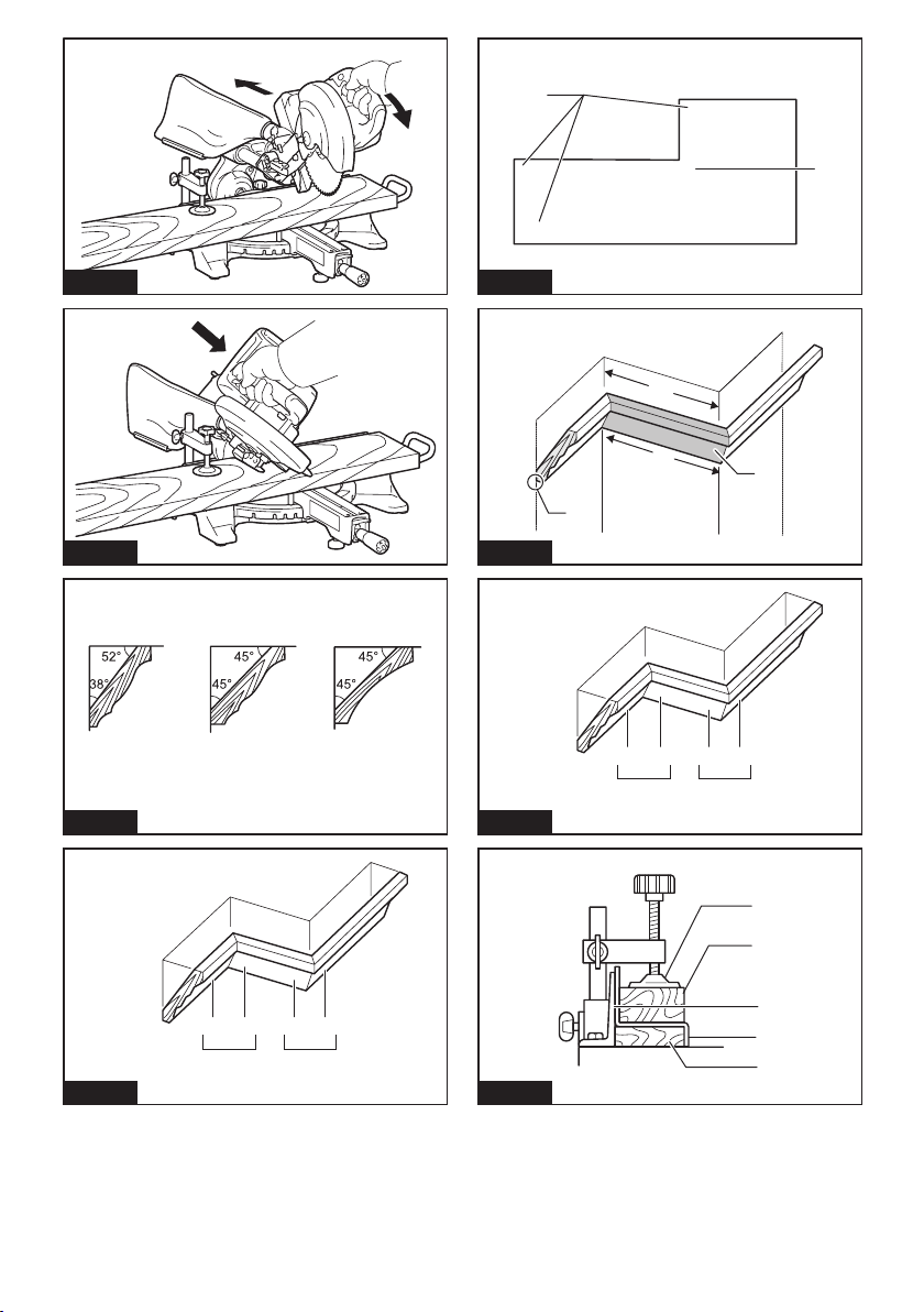
Slide (push) cutting (cutting wide
workpieces)
WARNING: Whenever performing a slide cut,
rst pull the carriage full towards you and press
the handle all the way down, then push the carriage toward the guide fence. Never start the cut
with the carriage not pulled fully toward you. If
you perform the slide cut without the carriage pulled
fully toward you unexpected kickback may occur and
serious personal injury may result.
WARNING: Never attempt to perform a slide
cut by pulling the carriage towards you. Pulling
the carriage towards you while cutting may cause
unexpected kickback resulting in possible serious
personal injury.
WARNING: Never perform the slide cut with
the handle locked in the lowered position.
WARNING: Never loosen the knob which
secures the carriage while the blade is rotating. A
loose carriage while cutting may cause unexpected
kickback resulting in possible in serious personal
injury.
► Fig.44
1. Loosen two clamp screws which secure the slide
poles counterclockwise so that the carriage can slide
freely.
2. Secure the workpiece with the proper type of vise.
3. Pull the carriage toward you fully.
4. Switch on the tool without the blade making any
contact and wait until the blade attains full speed.
5. Press the handle down and push the carriage
toward the guide fence and through the workpiece.
20 ENGLISH
Page 21
6. When the cut is completed, switch off the tool and
wait until the blade has come to a complete stop
before returning the blade to its fully elevated position.
Miter cutting
Refer to the previously covered "Adjusting the miter
angle".
Bevel cut
WARNING: After setting the blade for a bevel
cut, before operating the tool ensure that the carriage and blade will have free travel throughout
the entire range of the intended cut. Interruption of
the carriage or blade travel during the cutting operation may result in kickback and serious personal
injury.
WARNING: While making a bevel cut keep
hands out of the path of the blade. The angle of the
blade may confuse the operator as to the actual blade
path while cutting and contact with the blade will
result in serious personal injury
WARNING: The blade should not be raised
until it has come to a complete stop. During a
bevel cut the piece cut off may come to rest against
the blade. If the blade is raised while it is rotating the
cut-off piece maybe ejected by the blade causing
the material to fragment which may result in serious
personal injury.
CAUTION: (Only for tools with sub-fence)
Always set the sub-fence outside when performing left bevel cuts.
► Fig.45
1. Loosen the lever and tilt the saw blade to set the
bevel angle (Refer to the previously covered "Adjusting
the bevel angle"). Be sure to retighten the lever rmly to
secure the selected bevel angle safely.
2. Secure the workpiece with a vise.
3. Pull the carriage toward you fully.
4. Switch on the tool without the blade making any
contact and wait until the blade attains full speed.
5. Gently lower the handle to the fully lowered position while applying pressure in parallel with the blade
and push the carriage toward the guide fence to cut
the workpiece.
6. When the cut is completed, switch off the tool and
wait until the blade has come to a complete stop
before returning the blade to its fully elevated position.
NOTICE: When pressing down the handle, apply
pressure in parallel with the blade. If a force is
applied perpendicularly to the turn base or if the pressure direction is changed during a cut, the precision
of the cut will be impaired.
Compound cutting
Compound cutting is the process in which a bevel
angle is made at the same time in which a miter angle
is being cut on a workpiece. Compound cutting can be
performed at the angle shown in the table.
Miter angle Bevel angle
Left and Right 45° Left 0° - 45°
Right 50° Left 0° - 40°
Right 55° Left 0° - 30°
Right 57° Left 0° - 25°
When performing compound cutting, refer to "Press
cutting", "Slide cutting", "Miter cutting" and "Bevel cut"
explanations.
Cutting crown and cove moldings
Crown and cove moldings can be cut on a compound
miter saw with the moldings laid at on the turn base.
There are two common types of crown moldings and
one type of cove moldings; 52/38° wall angle crown
molding, 45° wall angle crown molding and 45° wall
angle cove molding.
► Fig.46: 1. 52/38° type crown molding 2. 45° type
crown molding 3. 45° type cove molding
There are crown and cove molding joints which are
made to t "Inside" 90° corners ((a) and (b) in the gure)
and "Outside" 90° corners ((c) and (d) in the gure.)
► Fig.47: 1. Inside corner 2. Outside corner
► Fig.48: 1. Inside corner 2. Outside corner
Measuring
Measure the wall width, and adjust the width of the
workpiece according to it. Always make sure that width
of the workpiece's wall contact edge is the same as wall
length.
► Fig.49: 1. Workpiece 2. Wall width 3. Width of the
workpiece 4. Wall contact edge
Always use several pieces for test cuts to check the
saw angles.
When cutting crown and cove moldings, set the bevel
angle and miter angle as indicated in the table (A) and
position the moldings on the top surface of the saw
base as indicated in the table (B).
In the case of left bevel cut
► Fig.50: 1. Inside corner 2. Outside corner
Table (A)
– Molding
For
inside
corner
For
outside
corner
position
in the
gure
(a) Left
(b) Left
(c)
(d) Right
Bevel angle Miter angle
52/38°
45° type 52/38°
type
33.9°
Left 30° Right
type
31.6°
31.6°
31.6°
45° type
Right
35.3°
Left
35.3°
Right
35.3°
21 ENGLISH
Page 22
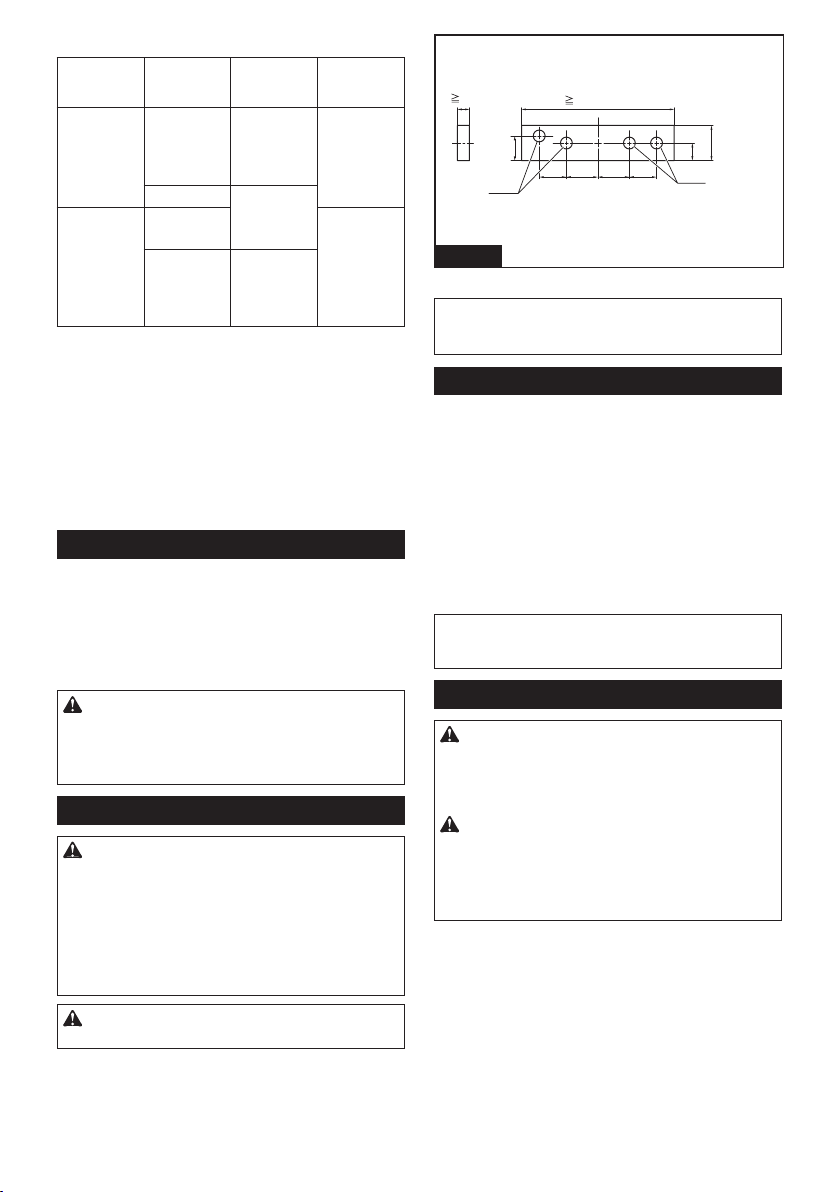
Table (B)
– Molding
For inside
corner
For outside
corner
position in
the gure
(a) Ceiling
(b) Wall contact
(c) Finished
Molding
edge against
guide fence
contact edge
should be
against guide
fence.
edge should
be against
guide fence.
contact edge
should be
against guide
fence.
Finished
piece
Finished
piece will be
on the Left
side of blade.
piece will be
on the Right
side of blade.(d) Ceiling
Example:
In the case of cutting 52/38° type crown molding for
position (a) in the above gure:
• Tilt and secure bevel angle setting to 33.9° LEFT.
• Adjust and secure miter angle setting to 31.6°
RIGHT.
•
Lay crown molding with its broad back (hidden)
surface down on the turn base with its CEILING
CONTACT EDGE against the guide fence on the saw.
•
The nished piece to be used will always be on the
LEFT side of the blade after the cut has been made.
Cutting aluminum extrusion
► Fig.51: 1. Vise 2. Spacer block 3. Guide fence
When securing aluminum extrusions, use spacer blocks
or pieces of scrap as shown in the gure to prevent
deformation of the aluminum. Use a cutting lubricant
when cutting the aluminum extrusion to prevent build-up
of the aluminum material on the blade.
aluminum extrusions. Thick aluminum extrusions
may come loose during operation and round alumi-
num extrusions cannot be secured rmly with this
tool.
4. Aluminum extrusion 5. Spacer block
CAUTION: Never attempt to cut thick or round
Wood facing
WARNING: Use screws to attach the wood
facing to the guide fence. The screws should be
installed so that the screw heads are below the
surface of the wood facing so that they will not
interfere with the positioning of the material being
cut. Misalignment of the material being cut can case
unexpected movement during the cutting operation
which may result in a loss of control and serious
personal injury.
CAUTION: Use the straight wood of even
thickness as the wood facing.
Use of wood facing helps to assure splinter-free cuts
in workpieces. Attach a wood facing to the guide fence
using the holes in the guide fence.
See the gure concerning the dimensions for a suggested wood facing.
15mm (5/8")
35mm
(1-3/8")
1
420mm (16-1/2")
92mm 85mm
100mm 70mm
(2-3/4")(3-15/16")(3-5/8")
(3-3/8")
27mm (1-1/16")
Fig.52
► Fig.52: 1. Holes
NOTICE: When the wood facing is attached, do
not turn the turn base with the handle lowered.
The blade and/or the wood facing will be damaged.
Cutting repetitive lengths
When cutting several pieces of stock to the same
length, ranging from 220 mm to 385 mm, use the set
plate (optional accessory). Install the set plate on the
holder (optional accessory) as shown in the gure.
► Fig.53: 1. Set plate 2. Holder 3. Screw
Align the cutting line on your workpiece with either the
left or right side of the groove in the kerf board, and
while holding the workpiece, move the set plate ush
against the end of the workpiece. Then secure the set
plate with the screw.
When the set plate is not used, loosen the screw and
turn the set plate out of the way.
NOTE: Use of the holder-rod assembly (optional
accessory) allows cutting repetitive lengths up to
2,200 mm approximately.
Groove cutting
WARNING:
of cut by using a wider type blade or dado blade.
Attempting to make a groove cut with a wider blade or
dado blade could lead to unexpected cutting results and
kickback which may result in serious personal injury.
WARNING: Be sure to return the stopper arm
to the original position when performing other
than groove cutting. Attempting to make cuts with
the stopper arm in the incorrect position could lead to
unexpected cutting results and kickback which may
result in serious personal injury.
For a dado type cut, perform as follows:
1. Adjust the lower limit position of the blade using
the adjusting screw and the stopper arm to limit the cutting depth of the blade. Refer to "Stopper arm" section
described on previously.
2. After adjusting the lower limit position of the blade,
cut parallel grooves across the width of the workpiece
using a slide (push) cut.
► Fig.54: 1. Cut grooves with blade
3. Remove the workpiece material between the
grooves with a chisel.
22 ENGLISH
Do not attempt to perform this type
50mm-60mm
(2"-2-3/8")
1
Page 23

Carrying tool
WARNING: Stopper pin is only for carrying
and storage purposes and should never be used
for any cutting operations. The use of the stopper
pin for cutting operations may cause unexpected
movement of the saw blade resulting in kickback and
serious personal injury.
CAUTION: Always secure all moving portions
before carrying the tool. If portions of the tool move
or slide while being carried loss of control or balance
may occur resulting in personal injury.
► Fig.55
1. Remove the battery cartridge.
2. Secure the blade at 0° bevel angle and the turn
base at the full right miter angle position.
3. Secure the slide poles so that the lower slide pole
is locked in the position of the carriage fully pulled to
operator and the upper poles are locked in the position
of the carriage fully pushed forward to the guide fence.
4. Lower the handle fully and lock it in the lowered
position by pushing in the stopper pin.
5. Carry the tool by holding both sides of the tool
base. If you remove the holders, dust bag, etc., you can
carry the tool more easily.
MAINTENANCE
WARNING: Always be sure that the blade is
sharp and clean for the best and safest performance. Attempting a cut with a dull and /or dirty blade
may cause kickback and result in a serious personal
injury.
CAUTION: Always be sure that the tool is
switched off and the battery cartridge is removed
before attempting to perform inspection or
maintenance.
NOTICE: Never use gasoline, benzine, thinner,
alcohol or the like. Discoloration, deformation or
cracks may result.
Adjusting the cutting angle
This tool is carefully adjusted and aligned at the factory,
but rough handling may have affected the alignment. If
your tool is not aligned properly, perform the following:
Miter angle
1. Push the carriage toward the guide fence and
tighten two clamp screws to secure the carriage.
2. Rotate the turn base until the pointer indicates 0°
on the miter scale.
3. Rotate the turn base slightly clockwise and counterclockwise to seat the turn base in the 0° miter notch.
(Leave as it is if the pointer does not indicate 0°.)
4. Loosen the hex socket bolt securing the guide
fence using the hex wrench.
► Fig.56: 1. Guide fence 2. Hex socket bolt
5. Lower the handle fully and lock it in the lowered
position by pushing in the stopper pin.
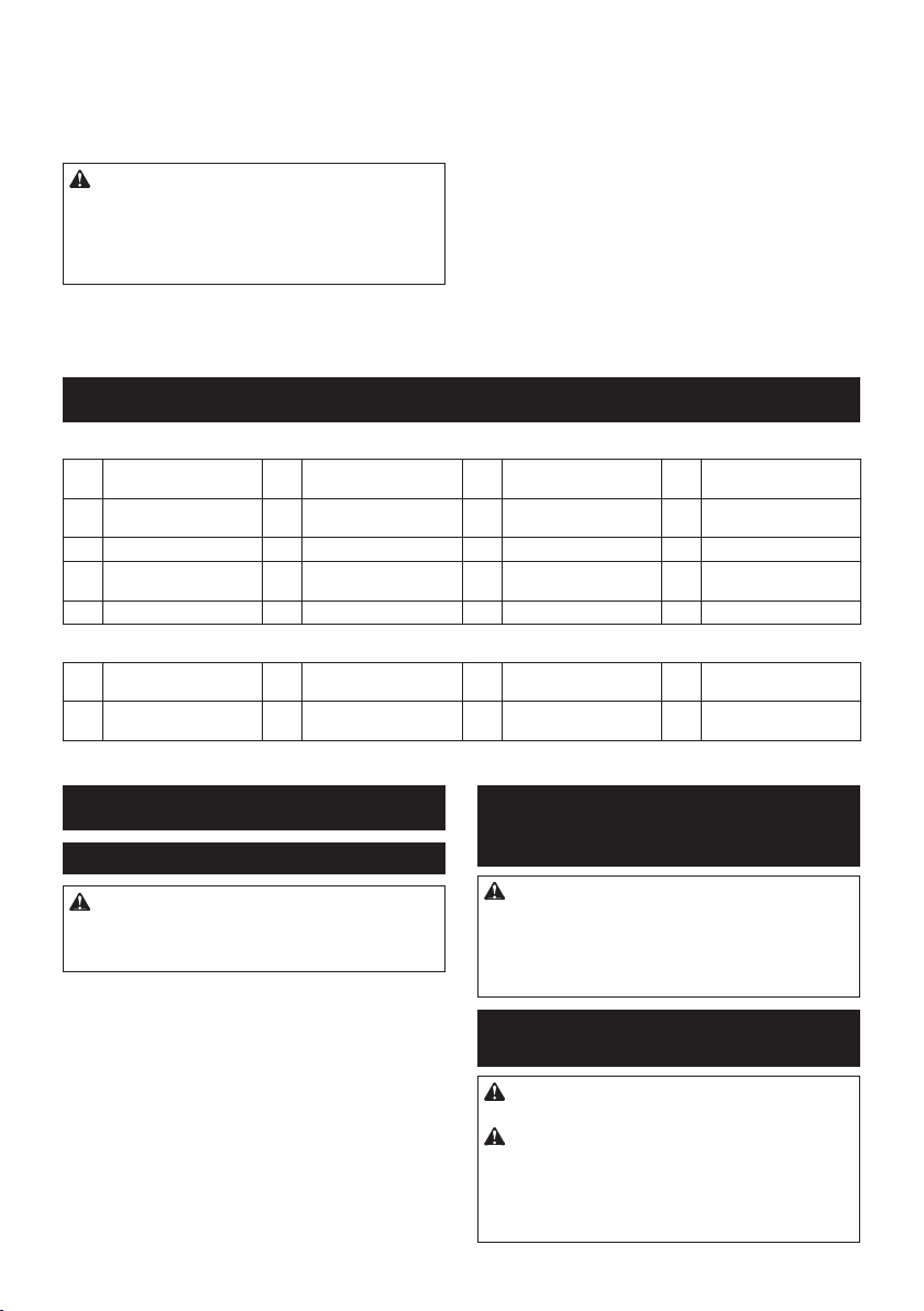
6. Adjust the guide fence until it makes a perpendic-
ular angle with the blade using a triangular rule, trysquare, etc. Then securely tighten the hex socket bolt
on the guide fence in order starting from the right side.
► Fig.57: 1. Triangular rule
7. Make sure that the pointer indicates 0° on the
miter scale. If the pointer does not indicate 0°, loosen
the screw which secures the pointer and adjust the
pointer so that it indicates 0°.
► Fig.58: 1. Screw 2. Miter scale 3. Pointer
Bevel angle
0° bevel angle
► Fig.59: 1. Lever 2. Arm holder 3. 0° degree bevel
angle adjusting bolt 4. Arm 5. Release
button
1. Push the carriage toward the guide fence and
tighten two clamp screws to secure the carriage.
2. Lower the handle fully and lock it in the lowered
position by pushing in the stopper pin.
3. Loosen the lever at the rear of the tool.
4. Turn the 0° bevel angle adjusting bolt (lower bolt)
on the right side of the arm two or three revolutions
counterclockwise to tilt the blade to the right.
5. Turn the 0° bevel angle adjusting bolt clockwise
carefully until the side of the blade makes a perpendic-
ular angle with the top surface of the turn base. Use the
triangular rule, try-square, etc. as a guide. Then tighten
the lever securely.
► Fig.60: 1. Triangular rule 2. Saw blade 3. Top sur-
face of turn table
6. Make sure that the pointer on the arm indicates 0°
on the bevel scale. If it does not indicate 0°, loosen the
screw which secures the pointer and adjust the pointer
so that it indicates 0°.
► Fig.61: 1. Bevel scale 2. Pointer 3. Screw
45° bevel angle
► Fig.62: 1. Left 45° bevel angle adjusting bolt
Adjust the 45° bevel angle only after performing 0°
bevel angle adjustment.
1. Loosen the lever and tilt the blade to the left fully.
2. Make sure that the pointer on the arm indicates
45° on the bevel scale. If the pointer does not indicate
45°, turn the 45° bevel angle adjusting bolt (upper bolt)
on the right side of the arm until the pointer indicates
45°.
After use
After use, wipe off chips and dust adhering to the tool
with a cloth or the like. Keep the blade guard clean
according to the directions in the previously covered
section titled "Blade guard". Lubricate the sliding portions with machine oil to prevent rust.
23 ENGLISH
Page 24
When storing the tool, pull the carriage toward you fully
so that the slide pole is thoroughly inserted into the turn
base.
To maintain product SAFETY and RELIABILITY,
repairs, any other maintenance or adjustment should
be performed by Makita Authorized or Factory Service
Centers, always using Makita replacement parts.
OPTIONAL
ACCESSORIES
WARNING: These Makita accessories or
attachments are recommended for use with your
Makita tool specied in this manual. The use of
any other accessories or attachments may result in
serious personal injury.
WARNING: Only use the Makita accessory
or attachment for its stated purpose. Misuse of
an accessory or attachment may result in serious
personal injury.
If you need any assistance for more details regard-
ing these accessories, ask your local Makita Service
Center.
• Carbide-tipped saw blades
• Vise assembly (Horizontal vise)
• Vertical vise
• Holder assembly
• Holder rod assembly
• Set plate
• Dust bag
• Triangular rule
• Hex wrench
• Makita genuine battery and charger
NOTE: Some items in the list may be included in the
tool package as standard accessories. They may
differ from country to country.
24 ENGLISH
Page 25

POLSKI (Instrukcja oryginalna)
DANE TECHNICZNE
Model: DLS714
Średnica tarczy 190 mm
Grubość tarczy tnącej 1,3–2,0 mm
Średnica otworu tarczy (w zależności od kraju) 20 mm lub 15,88 mm
Maks. kąt cięcia w poziomie W lewo 47°, w prawo 57°
Maks. kąt cięcia w pionie W lewo 45°, w prawo 5°
Prędkość bez obciążenia 5 700 min
Wymiary (dług. x szer. x wys.) 655 mm x 430 mm x 445 mm
Napięcie znamionowe Napięcie stałe 36 V
Akumulator BL1815N, BL1820, BL1820B BL1830, BL1830B, BL1840,
Ciężar netto 13,0 kg 13,5 kg
Maks. zakres cięcia (wys. x szer.) w przypadku tarczy o średnicy 190 mm
Kąt cięcia w poziomie Kąt cięcia w pionie
45° (w lewo) 0° 5° (w prawo)
0° 40 mm x 300 mm 52 mm x 300 mm 40 mm x 300 mm
45 mm x 265 mm
(WSKAZÓWKA 1)
45° (w lewo i w prawo) 40 mm x 212 mm 52 mm x 212 mm –
45 mm x 185 mm
(WSKAZÓWKA 2)
57° (w prawo) – 52 mm x 163 mm –
– 60 mm x 145 mm
60 mm x 265 mm
(WSKAZÓWKA 1)
60 mm x 185 mm
(WSKAZÓWKA 2)
(WSKAZÓWKA 3)
1. Maks. wydajność cięcia w przypadku użycia okładziny drewnianej o grubości 20 mm
2. Maks. wydajność cięcia w przypadku użycia okładziny drewnianej o grubości 15 mm
3. Maks. wydajność cięcia w przypadku użycia okładziny drewnianej o grubości 10 mm
• W związku ze stale prowadzonym przez naszą rmę programem badawczo-rozwojowym niniejsze dane mogą
ulec zmianom bez wcześniejszego powiadomienia.
• W innych krajach urządzenie może mieć odmienne parametry techniczne i może być wyposażone w inny
akumulator.
• Masa urządzenia wraz z akumulatorem obliczona zgodnie z procedurą EPTA 01/2003
Symbole
Poniżej pokazano symbole zastosowane na urządzeniu. Przed rozpoczęciem użytkowania należy zapoznać
się z ich znaczeniem.
Przeczytać instrukcję obsługi.
Dłonie i palce należy trzymać z dala od
tarczy.
Podczas cięcia pod kątem w pionie w lewą
stronę PROWADNICA POMOCNICZA
powinna być ustawiona w lewym położeniu. Niestosowanie się do tej zasady
może spowodować poważne obrażenia
operatora.
-1
BL1840B, BL1850, BL1850B,
BL1860B
–
–
–
Aby uniknąć obrażeń powodowanych
odpryskami, nie należy podnosić głowicy
tnącej po zakończeniu cięcia, aż do czasu
całkowitego zatrzymania się tarczy.
Podczas cięcia z przesunięciem najpierw
pociągnąć suport całkowicie do siebie
i przycisnąć uchwyt w dół, a następnie
popchnąć suport w stronę prowadnicy.
25 POLSKI
Page 26
Cd
Li-ion
Dotyczy tylko państw UE
Nie wyrzucać urządzeń elektrycznych ani
akumulatorów wraz z odpadami z gospo-
darstwa domowego!
Zgodnie z dyrektywami europejskimi w
sprawie zużytego sprzętu elektrycznego i
elektronicznego oraz baterii i akumulato-
rów oraz zużytych baterii i akumulatorów,
a także dostosowaniem ich do prawa
krajowego, zużyte urządzenia elektryczne,
baterie i akumulatory, należy składować
osobno i przekazywać do zakładu recyklingu działającego zgodnie z przepisami
dotyczącymi ochrony środowiska.
Ni-MH
Przeznaczenie
Narzędzie to jest przeznaczone do wykonywania precyzyjnych cięć prostych i ukośnych w drewnie.
Nie używać pilarki do cięcia materiałów innych niż
drewno, aluminium lub do nich podobnych.
Hałas
Typowy równoważny poziom dźwięku A określony w
oparciu o normę EN61029:
Poziom ciśnienia akustycznego (LpA): 88 dB(A)
Poziom mocy akustycznej (LWA): 97 dB (A)
Niepewność (K): 3 dB(A)
OSTRZEŻENIE: Nosić ochronniki słuchu.
Drgania
Całkowita wartość poziomu drgań (suma wektorów w 3
osiach) określona zgodnie z normą EN61029:
Emisja drgań (ah): 2,5 m/s2 lub mniej
Niepewność (K): 1,5 m/s
WSKAZÓWKA: Deklarowana wartość wytwarzanych
drgań została zmierzona zgodnie ze standardową
metodą testową i można ją wykorzystać do porównywania narzędzi.
WSKAZÓWKA: Deklarowaną wartość wytwarzanych
drgań można także wykorzystać we wstępnej ocenie
narażenia.
2
OSTRZEŻENIE: Drgania wytwarzane podczas
rzeczywistego użytkowania elektronarzędzia mogą
się różnić od wartości deklarowanej, w zależności od
sposobu jego użytkowania.
OSTRZEŻENIE:
żenie w rzeczywistych warunkach użytkowania należy
określić środki bezpieczeństwa w celu ochrony operatora (uwzględniając wszystkie elementy cyklu działania,
tj. czas, kiedy narzędzie jest wyłączone i kiedy pracuje
na biegu jałowym, a także czas, kiedy jest włączone).
W oparciu o szacowane nara-
Deklaracja zgodności WE
Dotyczy tylko krajów europejskich
Firma Makita oświadcza, że poniższe urządzenie(-a):
Oznaczenie maszyny: Ukośnica akumulatorowa
Model nr/typ: DLS714
Jest zgodne z wymogami określonymi w następujących
dyrektywach europejskich: 2006/42/EC
Jest/są produkowane zgodnie z następującymi normami lub dokumentami normalizacyjnymi: EN61029
Dokumentacja techniczna zgodna w wymaganiami
dyrektywy 2006/42/EC jest dostępna w:
Makita, Jan-Baptist Vinkstraat 2, 3070, Belgia
16.1.2015
Yasushi Fukaya
Dyrektor
Makita, Jan-Baptist Vinkstraat 2, 3070, Belgia
Ogólne zasady bezpiecznej
eksploatacji elektronarzędzi
OSTRZEŻENIE: Przeczytać wszystkie ostrze-
żenia bezpieczeństwa i wszystkie instrukcje.
Niezastosowanie się do wspomnianych ostrzeżeń i
instrukcji może doprowadzić do porażenia prądem
elektrycznym, pożaru i/lub poważnych obrażeń ciała.
Wszystkie ostrzeżenia i instrukcje należy zachować do wykorzystania w przyszłości.
Pojęcie „elektronarzędzie", występujące w wymienionych tu ostrzeżeniach, odnosi się do elektronarzędzia
zasilanego z sieci elektrycznej (z przewodem zasilającym) lub do elektronarzędzia akumulatorowego (bez
przewodu zasilającego).
Zasady bezpiecznej eksploatacji
ukośnicy akumulatorowej
1. Trzymać ręce z dala od drogi, po której porusza się tarcza tnąca. Nie dotykać obracającej
się z rozpędu tarczy. Grozi to w dalszym ciągu
poważnymi obrażeniami ciała.
2. Przed przystąpieniem do pracy dokładnie
sprawdzić tarczę tnącą pod kątem pęknięć lub
odkształceń.
Niezwłocznie wymieniać uszkodzone tarcze.
3. Wymieniać płytę nacięcia po zauważeniu na
niej śladów zużycia.
4. Należy stosować wyłącznie tarcze tnące
zalecane przez producenta, zgodne z normą
EN847-1.
5. Nie używać tarcz tnących wykonanych ze stali
szybkotnącej.
6. Należy stosować środki ochrony wzroku.
7. Nosić ochronniki słuchu, aby zmniejszyć
ryzyko utraty słuchu.
8. Podczas przenoszenia tarcz tnących oraz
ostrych materiałów należy nosić rękawice
(tarcze tnące należy umieszczać w uchwycie
zawsze, gdy jest to możliwe).
9. Podczas cięcia podłączać piłę do urządzenia
zbierającego pył.
10. Dobierać odpowiednie tarcze tnące do obrabianego materiału.
11. Przed przenoszeniem narzędzia należy zablokować wszystkie ruchome elementy. Podczas
podnoszenia lub przenoszenia narzędzia nie
używać jego osłony jako uchwytu.
26 POLSKI
Page 27

12. Nie uruchamiać piły bez założonych osłon.
Każdorazowo przed użyciem sprawdzić,
czy osłona prawidłowo się zamyka. Nie uruchamiać piły, jeśli osłona nie przesuwa się
swobodnie lub zamyka się z opóźnieniem.
Nie wolno w żadnym wypadku przywiązywać
osłony tarczy ani w inny sposób unieruchamiać jej w pozycji otwartej.
13. Dbać, aby na podłodze nie leżały luźne materiały i odpady, takie jak wióry czy ścinki.
14. Stosować wyłącznie tarcze tnące z oznaczeniem prędkości maksymalnej równej lub
wyższej niż wartość prędkości bez obciążenia
oznaczonej na narzędziu.
15. W przypadku gdy narzędzie jest wyposażone
w laser lub diodę LED, nie stosować podczas
ich wymiany innego typu lasera ani diody LED.
Zgłosić się do autoryzowanego centrum serwisowego w celu naprawy.
16. Nigdy nie usuwać żadnych ścinków ani innych
części elementu obrabianego z obszaru cięcia,
gdy narzędzie pracuje z nieosłoniętą tarczą
tnącą.
17. Nie wykonywać żadnych operacji, trzymając
obrabiany element w ręce. Obrabiany element
podczas wszystkich operacji musi być dobrze
zamocowany w podstawie obrotowej i prowadnicy
za pomocą zacisku. Nigdy nie trzymać obrabianego elementu ręką.
18. Upewnić się, że narzędzie jest stabilne przed
wykonaniem każdego cięcia.
19. W razie konieczności przymocować narzędzie
do stołu warsztatowego.
20. Podeprzeć dłuższe elementy obrabiane przy
użyciu odpowiednich podpór.
21. Nigdy nie ciąć małych elementów, których nie
można prawidłowo zamocować w zacisku.
Nieprawidłowo zamocowany element może zostać
odrzucony i spowodować poważne obrażenia
ciała.
22. Nie zbliżać rąk do tarczy tnącej.
23. Przed usunięciem obrabianego elementu lub
zmianą ustawień wyłączyć narzędzie i poczekać, aż tarcza tnąca zatrzyma się.
24. Odłączyć wtyczkę elektronarzędzia od źródła
zasilania i/lub akumulator przed przystąpieniem do wymiany tarczy lub serwisowania.
25. Kołek oporowy blokujący głowicę tnącą w
położeniu opuszczonym ma zastosowanie
wyłącznie przy przenoszeniu lub przechowywaniu urządzenia, nigdy podczas cięcia.
26. Nie używać narzędzia w pobliżu łatwopalnych
płynów lub gazów. Praca układu elektrycznego
narzędzia w obecności łatwopalnych płynów lub
gazów może spowodować wybuch i pożar.
27. Używać wyłącznie kołnierzy przeznaczonych
do tego urządzenia.
28. Uważać, aby nie uszkodzić wałka, kołnierzy
(szczególnie powierzchni mocujących) ani
śruby. Uszkodzenie tych części może być
przyczyną pęknięcia tarczy.
29. Upewnić się, że podstawa obrotowa jest
dobrze przymocowana i nie będzie się przesuwać podczas pracy.
30. Dla własnego bezpieczeństwa przed przystąpieniem do pracy usunąć wióry, drobne
kawałki materiału itp. z powierzchni stołu.
31. Należy unikać cięcia gwoździ. Przed przystąpieniem do pracy sprawdzić obrabiany element i usunąć z niego wszystkie gwoździe.
32. Przed włączeniem przełącznika sprawdzić, czy
blokada wałka została zwolniona.
33. Upewnić się, że tarcza w swoim najniższym
położeniu nie dotyka podstawy obrotowej.
34. Trzymać pewnie uchwyt urządzenia. Pamiętać,
że piła przesuwa się nieznacznie w górę lub w
dół na początku i na końcu cięcia.
35. Przed włączeniem przełącznika upewnić się, że
tarcza nie dotyka obrabianego elementu.
36. Przed rozpoczęciem obróbki danego elementu
pozwolić, aby urządzenie popracowało przez
chwilę bez obciążenia. Zwracać uwagę na
ewentualne drgania lub bicie osiowe, które
mogą wskazywać na nieprawidłowe zamocowanie lub niedokładne wyważenie tarczy.
37. Rozpocząć cięcie, gdy tarcza osiągnie pełną
prędkość.
38. Natychmiast przerwać pracę po zauważeniu
jakiejkolwiek nieprawidłowości.
39. Nie próbować blokować spustu przełącznika w
pozycji włączenia.
40. Zawsze zachować czujność, szczególnie
podczas wykonywania powtarzających się,
monotonnych czynności. Nie dać się zwieść
pozornemu poczuciu bezpieczeństwa. Tarcze
są niezwykle niebezpieczne.
41. Zawsze używać akcesoriów zalecanych w
niniejszej instrukcji obsługi. Używanie niewłaściwych akcesoriów, np. tarczy ściernych,
może być przyczyną obrażeń ciała.
42. Podczas wycinania rowków zachować
ostrożność.
43. Pył powstający w czasie pracy może zawierać
substancje chemiczne powodujące nowotwory, wady wrodzone oraz inne zaburzenia
płodności. Oto przykłady takich substancji:
• ołów w materiałach pomalowanych far-
bami zawierającymi ołów oraz
• arsen i chrom zawarty w impregnowanym
drewnie.
Stopień narażenia na te substancje zależy od
tego, jak często wykonywane są tego typu
prace. Aby zmniejszyć zagrożenie na powyższe substancje chemiczne: należy pracować
w miejscach dobrze wentylowanych i używać
sprawdzonych zabezpieczeń, takich jak maski
przeznaczone do odltrowywania mikroskopijnych cząstek.
44. Aby obniżyć poziom powstającego podczas
pracy hałasu, należy zawsze stosować ostre i
czyste tarcze.
45. Operator powinien przejść prawidłowe szkolenie w zakresie używania, regulacji i obsługi
urządzenia.
ZACHOWAĆ NINIEJSZE
INSTRUKCJE.
27 POLSKI
Page 28
OSTRZEŻENIE: NIE WOLNO pozwolić,
aby wygoda lub rutyna (nabyta w wyniku wielokrotnego używania urządzenia) zastąpiły ścisłe
przestrzeganie zasad bezpieczeństwa obsługi.
NIEWŁAŚCIWE UŻYTKOWANIE narzędzia lub
niestosowanie się do zasad bezpieczeństwa
podanych w niniejszej instrukcji obsługi może
prowadzić do poważnych obrażeń ciała.
Ważne zasady bezpieczeństwa
dotyczące akumulatora
1.
Przed użyciem akumulatora zapoznać się ze
wszystkimi instrukcjami i znakami ostrzegawczymi na (1) ładowarce, (2) akumulatorze i (3)
produkcie, w którym będzie używany akumulator.
2. Akumulatora nie wolno rozbierać.
3. Jeśli czas działania uległ znacznemu skróce-
niu, należy natychmiast przerwać pracę. Może
bowiem dojść do przegrzania, ewentualnych
poparzeń, a nawet eksplozji.
4. W przypadku przedostania się elektrolitu do
oczu, przemyć je czystą wodą i niezwłocznie
uzyskać pomoc lekarską. Może on bowiem
spowodować utratę wzroku.
5. Nie doprowadzać do zwarcia akumulatora:
(1) Nie dotykać styków materiałami przewo-
dzącymi prąd.
(2) Unikać przechowywania akumulatora w
pojemniku z metalowymi przedmiotami,
takimi jak gwoździe, monety itp.
(3) Chronić akumulator przed deszczem lub
wodą.
Zwarcie prowadzi do przepływu prądu elektrycznego o dużym natężeniu i przegrzania
akumulatora, co w konsekwencji może grozić
poparzeniami a nawet awarią urządzenia.
6. Narzędzia i akumulatora nie wolno przechowywać w miejscach, w których temperatura
osiąga bądź przekracza 50°C (122°F).
7. Akumulatorów nie wolno spalać, również tych
poważnie uszkodzonych lub całkowicie zużytych. Akumulator może eksplodować w ogniu.
8.
Chronić akumulator przed upadkiem i uderzeniami.
9. Nie wolno używać uszkodzonego akumulatora.
10. Stanowiące wyposażenie akumulatory lito-
wo-jonowe podlegają przepisom dotyczącym
produktów niebezpiecznych.
Na potrzeby transportu komercyjnego, np. świadczonego przez rmy trzecie czy spedycyjne,
należy przestrzegać specjalnych wymagań w
zakresie pakowania i oznaczania etykietami.
Przygotowanie produktu do wysyłki wymaga skonsultowania się ze specjalistą ds. materiałów niebezpiecznych. Należy także przestrzegać przepisów
krajowych, które mogą być bardziej szczegółowe.
Zakleić taśmą lub zaślepić otwarte styki akumulatora oraz zabezpieczyć go, aby nie mógł się przesuwać w opakowaniu.
11. Postępować zgodnie z przepisami lokalnymi
dotyczącymi usuwania akumulatorów.
ZACHOWAĆ NINIEJSZE
INSTRUKCJE.
PRZESTROGA:
akumulatorów rmy Makita. Używanie nieoryginalnych
akumulatorów rm innych niż Makita lub akumulatorów,
które zostały zmodykowane, może spowodować wybuch
akumulatora i pożar, obrażenia ciała oraz zniszczenie
mienia. Stanowi to również naruszenie warunków gwarancji rmy Makita dotyczących narzędzia i ładowarki.
Używać wyłącznie oryginalnych
Wskazówki dotyczące zachowania maksymalnej trwałości
akumulatora
1. Akumulator należy naładować zanim zostanie
do końca rozładowany. Po zauważeniu spadek
mocy narzędzia należy przerwać pracę i naładować akumulator.
2. Nie wolno ładować powtórnie w pełni naładowanego akumulatora. Przeładowanie akumulatora skraca jego trwałość.
3. Akumulator należy ładować w temperaturze
pokojowej w przedziale 10–40°C (50–104°F). W
przypadku gorącego akumulatora przed przystąpieniem do ładowania należy poczekać, aż
ostygnie.
4. Akumulatory niklowo-wodorkowe należy naładować po okresie długiego nieużytkowania
(dłuższego niż sześć miesięcy).
OPIS CZĘŚCI
► Rys.1
1 Przycisk blokady 2 Spust przełącznika 3 Obudowa tarczy 4 Śruba regulacyjna
5 Śruba regulacyjna
(maksymalnego zakresu
cięcia)
9 Osłona tarczy 10 Zacisk pionowy 11 Prowadnica 12 Podpora
13 Dźwignia blokady (pod-
stawy obrotowej)
17 Wskaźnik (kąta cięcia w
poziomie)
6 Ramię ogranicznika 7 Worek na pył 8 Podziałka kąta cięcia
14 Rączka (podstawy
obrotowej)
18 Podstawa obrotowa - - - -
15 Śruba regulacyjna (pod-
stawy obrotowej)
28 POLSKI
(dolnego położenia
granicznego)
w pionie
16 Płyta nacięcia
Page 29
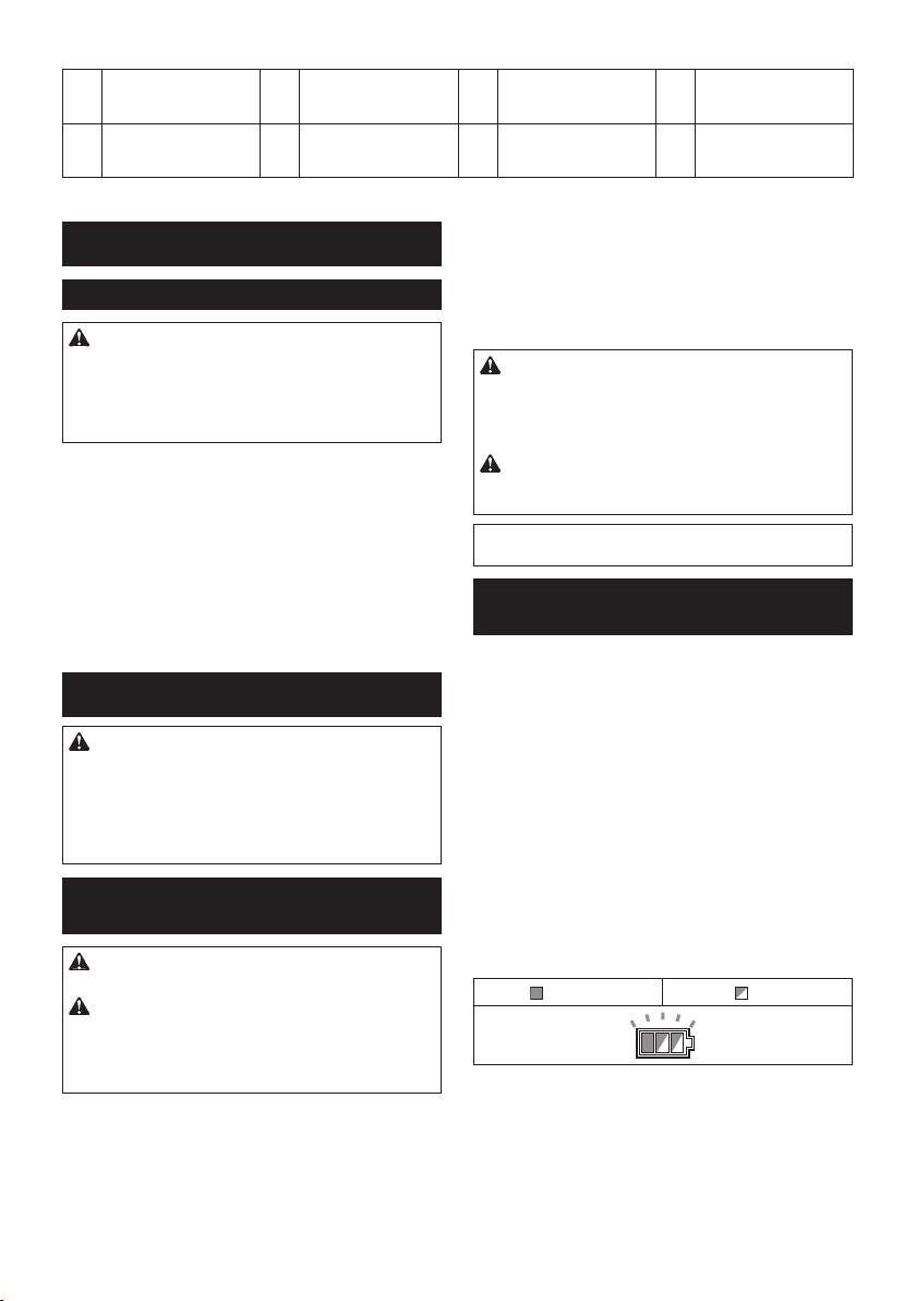
► Rys.2
19 Pręt przesuwu 20 Śruba skrzydełkowa
23 Dźwignia (regulacji kąta
cięcia w pionie)
(blokowania górnego
pręta przesuwu)
24 Pręt przesuwu (dolny) 25 Śruba skrzydełkowa
INSTALACJA
Mocowanie do stołu roboczego
OSTRZEŻENIE: Upewnić się, że narzędzie
nie będzie się przemieszczać po powierzchni, na
której zostało umieszczone. Przemieszczenie się
ukośnicy po powierzchni podczas pracy może spowodować utratę kontroli na urządzeniem i poważne
obrażenia ciała.
1. Przymocuj podstawę do poziomej, stabilnej
powierzchni, przykręcając ją dwoma wkrętami. Pomoże
to zapobiec przewróceniu się urządzenia i możliwym
obrażeniom ciała.
► Rys.3: 1. Wkręt
2. Przekręć śrubę regulującą w prawo lub lewo, tak
aby stykała się z powierzchnią podłoża, co zapewni
stabilność narzędzia.
► Rys.4: 1. Śruba regulacyjna
OPIS DZIAŁANIA
OSTRZEŻENIE: Przed przystąpieniem do
regulacji lub przeglądu narzędzia upewnić się, że
jest ono wyłączone, a akumulator został wyjęty.
Jeśli urządzenie pozostanie włączone lub pozostanie
w nim akumulator, może to spowodować poważne
obrażenia ciała w wyniku przypadkowego uruchomienia urządzenia.
Wkładanie i wyjmowanie
akumulatora
21 Klucz imbusowy 22 Śruba zaciskowa (bloko-
(blokowania dolnego
pręta przesuwu)
Aby włożyć akumulator, wyrównaj występ na akumulatorze z rowkiem w obudowie i wsuń go na swoje
miejsce. Akumulator należy wsunąć do oporu, aż się
zatrzaśnie na miejscu, co jest sygnalizowane delikatnym kliknięciem. Jeśli w górnej części przycisku jest
widoczny czerwony wskaźnik, akumulator nie został
całkowicie zatrzaśnięty.
PRZESTROGA: Akumulator należy włożyć
do końca, tak aby czerwony wskaźnik nie był
widoczny. W przeciwnym razie może przypadkowo
wypaść z narzędzia, powodując obrażenia operatora
lub osób postronnych.
PRZESTROGA: Nie wkładać akumulatora na
siłę. Jeśli akumulator nie daje się swobodnie wsunąć,
oznacza to, że został włożony nieprawidłowo.
WSKAZÓWKA: Narzędzie nie działa w przypadku
włożenia tylko jednego akumulatora.
wania podpory)
- -
Układ zabezpieczenia narzędzia/
akumulatora
Narzędzie jest wyposażone w układ zabezpieczenia
narzędzia/akumulatora. Układ automatycznie odcina
zasilanie silnika w celu wydłużenia trwałości narzędzia
i akumulatora. Narzędzie zostanie automatycznie
zatrzymane podczas pracy w następujących sytuacjach
związanych z narzędziem lub akumulatorem:
Zabezpieczenie przed przeciążeniem
W przypadku obsługi narzędzia w sposób powodujący
pobór nadmiernie wysokiego prądu narzędzie zostanie
automatycznie zatrzymane bez żadnej sygnalizacji. W
takiej sytuacji należy wyłączyć narzędzie i zaprzestać
wykonywania czynności powodującej przeciążenie
narzędzia. Następnie należy włączyć narzędzie w celu
jego ponownego uruchomienia.
PRZESTROGA: Przed włożeniem lub wyjęciem
akumulatora należy zawsze wyłączyć narzędzie.
PRZESTROGA: Podczas wkładania lub wyjmo-
wania akumulatora należy mocno trzymać narzę-
dzie i akumulator. W przeciwnym razie mogą się one
wyślizgnąć z rąk, powodując uszkodzenie narzędzia
lub akumulatora i obrażenia ciała.
► Rys.5: 1. Czerwony wskaźnik 2. Przycisk
3. Akumulator
Aby wyjąć akumulator, przesuń przycisk znajdujący się
w przedniej jego części i wysuń akumulator.
Zabezpieczenie przed przegrzaniem
Włączone Miga
W przypadku przegrzania narzędzie zostanie automatycznie zatrzymane, a wskaźnik akumulatora
zacznie migać przez około 60 s. W takiej sytuacji przed
ponownym włączeniem należy poczekać, aż narzędzia
ostygnie.
29 POLSKI
Page 30
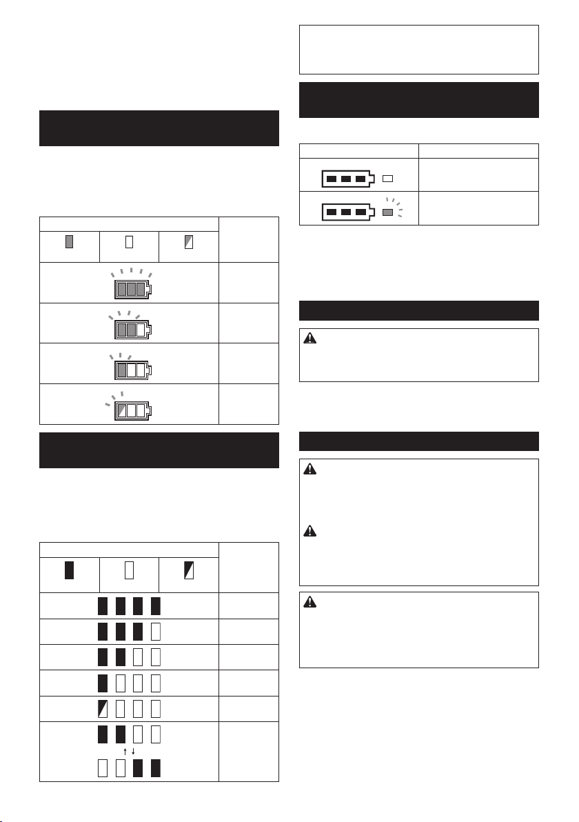
Zabezpieczenie przed nadmiernym
rozładowaniem
Gdy poziom naładowania akumulatora spadnie, narzędzie zostanie automatycznie zatrzymane. Jeśli produkt
nie działa pomimo włączenia przełączników, należy
wyjąć akumulatory z narzędzia i naładować je.
Wskazanie stanu naładowania
akumulatora
► Rys.6: 1. Wskaźnik akumulatora 2. Przycisk
Nacisnąć przycisk kontrolny, aby sprawdzić poziom
naładowania akumulatora. Wskaźniki akumulatora
odpowiadają każdemu akumulatorowi.
kontrolny
Stan wskaźnika akumulatora Stan nała-
Włączony
Wyłączony
Miga
dowania
akumulatora
50% do 100%
20% do 50%
WSKAZÓWKA: Zależnie od warunków użytkowania
i temperatury otoczenia, wskazywany poziom może
nieznacznie się różnić od rzeczywistego stanu nała-
dowania akumulatora.
Funkcja automatycznej zmiany
prędkości
► Rys.8: 1. Wskaźnik trybu
Status wskaźnika trybu Tryb pracy
Tryb wysokiej prędkości
Tryb wysokiego momentu
Narzędzie to może pracować w „trybie wysokiej prędkości” oraz w „trybie wysokiego momentu”. Narzędzie
zmienia automatycznie tryb pracy w zależności od jego
obciążenia. Włączenie się wskaźnika trybu podczas
pracy oznacza, że narzędzie pracuje w trybie wyso-
kiego momentu.
Kołek oporowy
0% do 20%
Naładować
akumulator.
Wskazanie stanu naładowania
akumulatora
Tylko w przypadku akumulatorów ze wskaźnikiem
► Rys.7: 1. Lampki wskaźnika 2. Przycisk kontrolny
Nacisnąć przycisk kontrolny na akumulatorze w celu
wyświetlenia stanu naładowania akumulatora. Lampki
wskaźnika zaświecą się przez kilka sekund.
Lampki wskaźnika Pozostała
Świeci się Wyłączony Miga
energia
akumulatora
75–100%
50–75%
25–50%
0–25%
Naładować
akumulator.
Akumulator
może nie
działać
poprawnie.
PRZESTROGA: Podczas zwalniania koła
oporowego przez cały czas trzymać uchwyt. W
przeciwnym razie uchwyt odskoczy do góry, co może
spowodować obrażenia ciała.
Aby zwolnić kołek oporowy, należy, naciskając uchwyt
w dół, wyciągnąć kołek oporowy.
► Rys.9: 1. Kołek oporowy
Osłona tarczy
OSTRZEŻENIE: Nie wolno modykować ani
zdejmować osłony tarczy i sprężyny mocującej
osłonę. Odsłonięta w wyniki modykacji tarcza może
spowodować poważne obrażenia ciała podczas
użytkowania.
OSTRZEŻENIE: Nie wolno użytkować narzę-
dzia, jeśli osłona tarczy lub sprężyna są uszkodzone, wadliwe lub wymontowane. Użytkowanie
narzędzia z uszkodzoną, wadliwą lub wymontować
osłoną może spowodować poważne obrażenia ciała.
PRZESTROGA: Osłonę tarczy należy przez cały
czas utrzymywać w dobrym stanie w celu zapewnienia bezpiecznego działania. Zatrzymać pracę natychmiast po zauważeniu jakichkolwiek nieprawidłowości
osłony tarczy. Upewnić się, czy sprężynowy mechanizm powrotny osłony działa prawidłowo.
Narzędzia z dźwignią zwalniania osłony tarczy
► Rys.10: 1. Osłona tarczy A 2. Osłona tarczy B
Podczas opuszczania uchwytu osłona tarczy A pod-
nosi się automatycznie. Osłona tarczy B podnosi się
po dotknięciu z elementem obrabianym. Osłony są
wyposażone w sprężynę, dlatego wracają do pierwotnego położenia po zakończeniu cięcia i podniesieniu
uchwytu.
30 POLSKI
Page 31

Narzędzie bez dźwigni zwalniania osłony tarczy
► Rys.11: 1. Osłona tarczy
Podczas opuszczania uchwytu osłona tarczy podnosi
się automatycznie. Osłona jest wyposażona w sprężynę, dlatego wraca do pierwotnego położenia po
zakończeniu cięcia i podniesieniu uchwytu.
Czyszczenie
► Rys.12: 1. Osłona tarczy
Jeśli przezroczysta osłona tarczy zabrudzi się albo
pokryje pyłem w takim stopniu, że tarcza i/lub obrabiany
element nie są dobrze widoczne, należy wyjąć akumulator i starannie wyczyścić osłonę wilgotną ściereczką.
Nie wolno stosować rozpuszczalników ani środków
czyszczących na bazie benzyny, gdyż może to spowodować uszkodzenie plastikowej osłony.
Do czyszczenia należy podnieść osłonę tarczy zgodnie
z informacjami z części „Zakładanie lub zdejmowanie
tarczy tnącej”.
Po zakończeniu czyszczenia należy z powrotem założyć tarczę i pokrywę środkową oraz dokręcić śrubę
imbusową.
1. Upewnij się, że urządzenie jest wyłączone, a
akumulator wyjęty.
2. Przykręć śrubę imbusową w lewą stronę przy
użyciu dostarczonego klucza, przytrzymując pokrywę
środkową.
3. Podnieś osłonę tarczy i pokrywę środkową.
4. Po zakończeniu czyszczenia załóż z powrotem
pokrywę środkową i dokręć śrubę imbusową, wykonując czynności z powyższych punktów w odwrotnej
kolejności.
OSTRZEŻENIE: Nie wolno wymontowywać
sprężyny przytrzymującej osłonę tarczy. Jeśli
osłona się uszkodzi lub przebarwi wraz z upływem
czasu lub pod wpływem promieniowania UV, należy
skontaktować się z punktem serwisowym narzędzi
Makita w celu wymiany. NIE BLOKOWAĆ ANI NIE
ZDEJMOWAĆ OSŁONY.
Pozycjonowanie płyty nacięcia
Narzędzie jest wyposażone w płyty nacięcia zamocowane w podstawie obrotowej, które minimalizują
wystrzępienie materiału po stronie wyjściowej podczas
cięcia. Płyty nacięcia są wyregulowane fabrycznie tak,
aby tarcza tnąca nie stykała się z nimi. Przed użyciem
narzędzia należy wyregulować płyty nacięcia w następujący sposób:
1. Wyjmij akumulator. Odkręć wszystkie wkręty
(dwa po lewej i dwa po prawej stronie) mocujące płyty
nacięcia.
► Rys.13: 1. Płyta nacięcia 2. Wkręt
2. Przykręć je z powrotem tylko do takiego stopnia,
aby płyty nacięcia można było łatwo przesuwać ręką.
3. Opuść całkowicie uchwyt i wepchnij kołek oporowy, aby zablokować uchwyt w najniższej pozycji.
4. Poluzuj dwie śruby zaciskowe, które unieruchamiają pręty przesuwu.
► Rys.14: 1. Śruba skrzydełkowa
5. Pociągnij do siebie suport do oporu.
6. Wyreguluj płyty nacięcia, tak aby ledwie stykały
się z zębami tarczy.
► Rys.15
► Rys.16: 1. Tarcza tnąca 2. Zęby tarczy 3. Płyta
nacięcia 4. Cięcie pod kątem w pionie z
lewej strony 5. Cięcie proste
7. Dokręć przednie wkręty (niezbyt mocno).
8. Popchnij suport ku prowadnicy do oporu i wyre-
guluj płyty nacięcia, tak aby ledwie stykały się z zębami
tarczy.
9. Dokręć tylne wkręty (niezbyt mocno).
10. Po wyregulowaniu płyt nacięcia zwolnij kołek opo-
rowy i podnieś uchwyt. Teraz dokręć solidnie wszystkie
wkręty.
UWAGA: Po ustawieniu kąta cięcia w pionie
należy sprawdzić, czy płyty nacięcia są prawidłowo wyregulowane. Prawidłowe ustawienie płyt
nacięcia zapewni lepsze podparcie obrabianego
elementu i zmniejszy wystrzępienie materiału.
Zachowanie maksymalnego zakresu
cięcia
Narzędzie jest fabrycznie wyregulowane w taki sposób,
aby zapewnić maksymalny zakres cięcia dla tarcz
tnących o średnicy 190 mm.
Zakładając nową tarczę, zawsze należy sprawdzić jej
dolne położenie graniczne i w razie potrzeby wyregulować w następujący sposób:
1. Wyjmij akumulator. Popchnij do oporu suport do
prowadnicy i całkowicie obniż uchwyt.
► Rys.17: 1. Śruba regulacyjna 2. Prowadnica
2. Za pomocą klucza imbusowego przekręć śrubę
regulacyjną, aż tarcza tnąca zejdzie nieco poniżej przekroju poprzecznego prowadnicy i górnej powierzchni
podstawy obrotowej.
► Rys.18
3. Obróć ręką tarczę, przytrzymując uchwyt w skrajnym dolnym położeniu, aby upewnić się, że tarcza nie
dotyka żadnej części dolnej podstawy. W razie potrzeby
skoryguj nieznacznie ustawienie.
OSTRZEŻENIE: Po zamontowaniu nowej
tarczy (gdy akumulator jest wyjęty) należy sprawdzić, czy tarcza nie styka się z dolną podstawą,
gdy uchwyt jest całkowicie opuszczony. Jeśli
tarcza styka się z podstawą, może to spowodować
odrzut i stać się przyczyną poważnych obrażeń ciała.
► Rys.19
Ramię ogranicznika
Dolne położenie graniczne tarczy można łatwo wyregulować za pomocą ramienia ogranicznika. Aby ją
wyregulować, należy przesunąć ramię ogranicznika w
kierunku wskazywanym przez strzałkę, jak pokazano
na rysunku. Przekręcić śrubę regulacyjną i całkowicie
obniżyć uchwyt, aby sprawdzić rezultat regulacji.
► Rys.20: 1. Śruba regulacyjna 2. Ramię
ogranicznika
31 POLSKI
Page 32

Prowadnica pomocnicza
W zależności od kraju
PRZESTROGA: Przed przystąpieniem do
wykonywania cięć pod kątem w pionie z lewej
strony należy odwrócić prowadnicę pomocniczą
na zewnątrz. W przeciwnym razie prowadnica może
stykać się z tarczą lub częścią narzędzia, grożąc
operatorowi poważnymi obrażeniami ciała.
► Rys.21: 1. Prowadnica pomocnicza
Narzędzie jest wyposażone w prowadnicę pomocniczą.
Standardowo prowadnica pomocnicza jest ustawiona
do wewnątrz. Jednakże w przypadku wykonywania cięć
pok kątem w pionie z lewej strony prowadnicę należy
odwrócić na zewnątrz.
Regulacja kąta cięcia w poziomie
► Rys.22: 1. Podstawa obrotowa 2. Wskaźnik
3. Podziałka kąta cięcia w poziomie
4. Dźwignia blokady 5. Rączka
1. Poluzuj rączkę, obracając ją w lewo.
2. Naciśnij dźwignię blokady i przytrzymując ją w
takim położeniu, ustaw kąt na podstawie obrotowej.
Kieruj się przy tym położeniem wskaźnika względem
podstawy obrotowej.
3. Dokręć mocno rączkę w prawą stronę.
PRZESTROGA: Po zmianie kąta cięcia w poziomie należy zawsze unieruchomić podstawę obrotową, dokręcając mocno rączkę.
UWAGA: Obracają podstawę obrotową należy
całkowicie podnieść uchwyt.
Regulacja kąta cięcia w pionie
Aby zmienić ustawienie kąta cięcia w pionie, należy
poluzować dźwignię z tyłu narzędzia, obracając ją w
lewo.
► Rys.23: 1. Dźwignia 2. Przycisk zwalniający
Aby pochylić tarczę w lewo, należy trzymać za uchwyt
i przechylić suport. Należy się przy tym kierować położeniem wskaźnika względem podziałki kąta cięcia w
pionie. Następnie dokręcić mocno dźwignię w prawą
stronę, aby unieruchomić ramię.
► Rys.24: 1. Wskaźnik 2. Podziałka kąta cięcia w
pionie 3. Ramię
Aby pochylić tarczę w prawo, należy trzymać za uchwyt
i przechylić suport lekko w lewo, a następnie wcisnąć
przycisk zwalniający. Gdy przycisk zwalniający jest wciśnięty, przechylić tarczę tnącą w prawo. Teraz dokręcić
mocno dźwignię.
PRZESTROGA: Po zmianie ustawienia kąta cięcia w pionie należy zawsze unieruchomić ramię,
dokręcając dźwignię w prawo.
UWAGA: Przy pochylaniu tarczy tnącej uchwyt
musi być całkowicie podniesiony.
UWAGA: Podczas zmiany kąta cięcia w pionie
upewnij się, że płyty nacięcia są ustawione w
prawidłowym położeniu — zgodnie z zaleceniami
zawartymi w rozdziale „Pozycjonowanie płyt
nacięcia”.
Regulacja położenia dźwigni
Jeśli dźwignia z biegiem czasu przestanie zapewniać pełne dociśnięcie, należy zmienić jej położenie.
Dźwignię można przestawiać co 30°.
Odkręcić i wyjąć śrubę mocującą dźwignię. Wyjąć
dźwignię i zamontować ją z powrotem w taki sposób,
aby znalazła się lekko ponad poziomem. Następnie
dokręcić dobrze dźwignię śrubą.
► Rys.25: 1. Dźwignia 2. Śruba
Działanie przełącznika
OSTRZEŻENIE: Przed włożeniem akumula-
tora do narzędzia należy zawsze sprawdzić, czy
spust przełącznika działa prawidłowo oraz czy
wraca do położenia wyłączenia po zwolnieniu.
Obsługa narzędzia, w przypadku nieprawidłowego
działania przełącznika, może prowadzić do utraty
kontroli nad narzędziem oraz poważnych obrażeń
ciała.
OSTRZEŻENIE: Nie używać kłódek z pałą-
kiem lub linką o średnicy mniejszej niż 6,35 mm
(1/4"). Mniejsza średnica pałąka lub linki może
spowodować nieprawidłowe zablokowanie narzędzia
w położeniu wyłączenia i umożliwić przypadkowe
uruchomienie, co może być przyczyną poważnych
obrażeń ciała.
OSTRZEŻENIE: NIE WOLNO użytkować
narzędzia, w którym spust przełącznika działa
nieprawidłowo. Narzędzie z niesprawnym przełącz-
nikiem stanowi POWAŻNE ZAGROŻENIE i należy
je naprawić przed ponownym użyciem; nieprzestrzeganie tego zalecenia grozi poważnymi obrażeniami
ciała.
OSTRZEŻENIE: Ze względów bezpieczeństwa
narzędzie jest wyposażone w przycisk blokady, który
zapobiega przypadkowemu uruchomieniu narzędzia.
NIE WOLNO używać narzędzia, jeśli można je
uruchomić tylko za pomocą spustu przełącznika
bez uprzedniego wciśnięcia przycisku blokady.
Niesprawny, wymagający naprawy przełącznik może
spowodować przypadkowe uruchomienie urządzenia
i poważne obrażenia ciała. PRZED dalszym użytkowaniem narzędzia należy przekazać je do punktu
serwisowego narzędzi Makita w celu naprawy.
OSTRZEŻENIE: NIE WOLNO pomijać ani
blokować działania przycisku blokady poprzez
zaklejanie go taśmą ani w inny sposób. Wyłącznik
z pominiętym lub zablokowanym przyciskiem blokady
może spowodować przypadkowe uruchomienie
narzędzia i poważne obrażenia ciała.
32 POLSKI
Page 33

UWAGA: Nie ciągnąć na siłę spustu przełącznika
bez wcześniejszego wciśnięcia przycisku blo-
kady. Można w ten sposób połamać przełącznik.
Narzędzia z dźwignią zwalniania osłony tarczy
Aby uniknąć przypadkowego pociągnięcia spustu przełącznika, urządzenie jest wyposażone w przycisk blokady. Aby uruchomić narzędzie, należy nacisnąć dźwignię zwalniania osłony tarczy, wcisnąć przycisk blokady
i pociągnąć za spust przełącznika. W celu zatrzymania
urządzenia wystarczy zwolnić spust przełącznika.
Przycisk blokady można nacisnąć z prawej lub z lewej
strony.
W spuście przełącznika znajduje się otwór, który
pozwala zablokować narzędzie w stanie wyłączenia
przy użyciu kłódki.
► Rys.26: 1. Dźwignia zwalniania osłony tarczy
2. Spust przełącznika 3. Przycisk blokady
4. Otwór na kłódkę
Narzędzie bez dźwigni zwalniania osłony tarczy
Aby uniknąć przypadkowego pociągnięcia spustu
przełącznika, urządzenie jest wyposażone w przycisk
blokady. Aby uruchomić urządzenie,naciśnij przycisk
blokady i pociągnij za spust. W celu zatrzymania urządzenia wystarczy zwolnić spust przełącznika.
Przycisk blokady można nacisnąć z prawej lub z lewej
strony.
W spuście przełącznika znajduje się otwór, który
pozwala zablokować narzędzie w stanie wyłączenia
przy użyciu kłódki.
► Rys.27: 1. Przycisk blokady 2. Spust przełącznika
3. Otwór na kłódkę
MONTAŻ
OSTRZEŻENIE: Przed przystąpieniem do
prac konserwacyjnych przy narzędziu upewnić
się, czy narzędzie jest wyłączone oraz czy został
wyjęty akumulator. Niewyłączenie narzędzie i nie-
wyjęcie akumulatora może być przyczyną poważnych
obrażeń ciała.
Miejsce na klucz imbusowy
Klucz imbusowy jest przechowywany w miejscu pokazanym na rysunku. Gdy klucz imbusowy jest potrzebny,
można go wyjąć z uchwytu.
Po użyciu klucz imbusowy należy umieścić z powrotem
w uchwycie.
► Rys.28: 1. Uchwyt klucza 2. Klucz imbusowy
Zakładanie lub zdejmowanie tarczy
tnącej
PRZESTROGA: Do zakładania i zdejmowania
tarczy należy używać wyłącznie dostarczonego
klucza imbusowego rmy Makita. Niestosowanie
się do tego zalecenia może spowodować nadmierne
lub niedostateczne dokręcenie śruby imbusowej.
Może to spowodować obrażenia ciała.
Aby zdjąć tarczę tnącą, należy wykonać następujące
czynności:
1. Zablokuj uchwyt w podniesionej pozycji, wciskając
kołek oporowy.
► Rys.29: 1. Kołek oporowy
2. Poluzuj kluczem imbusowym śrubę imbusową
przytrzymującą pokrywę środkową, obracając ją w lewą
stronę. Następnie podnieś osłonę tarczy i pokrywę
środkową.
► Rys.30: 1. Pokrywa środkowa 2. Śruba imbusowa
3. Klucz imbusowy 4. Osłona tarczy
3. Naciśnij blokadę wałka, aby zablokować wrze-
ciono, a następnie odkręć w prawo śrubę imbusową
za pomocą klucza imbusowego. Następnie wyjmij
śrubę imbusową z wrzeciona, zewnętrzny kołnierz oraz
tarczę.
► Rys.31: 1. Blokada wałka 2. Śruba imbusowa
3. Kołnierz zewnętrzny
4. Jeśli kołnierz wewnętrzny jest wymontowany,
należy go zamontować na wrzecionie w taki sposób,
aby część mocowania tarczy była zwrócona w stronę
tarczy. Jeśli kołnierz zostanie zamontowany w nieprawidłowy sposób, będzie on tarł o maszynę.
► Rys.32: 1. Kołnierz zewnętrzny 2. Tarcza tnąca
3. Kołnierz wewnętrzny 4. Śruba imbusowa
(z lewym gwintem) 5. Wrzeciono 6. Część
mocowania tarczy
Aby założyć tarczę, należy wykonać następujące
czynności:
1. Załóż ostrożnie tarczę na kołnierz wewnętrzny.
Upewniaj się, że kierunek strzałki na tarczy zgadza się
z kierunkiem strzałki na jej obudowie.
► Rys.33: 1. Tarcza tnąca 2. Strzałka
2. Załóż kołnierz zewnętrzny i śrubę imbusową, a
następnie dokręć dobrze śrubę imbusową (z lewym
gwintem) wrzeciona w lewą stronę za pomocą klucza
imbusowego, wciskając jednocześnie blokadę wałka.
3. Ustaw osłonę tarczy i pokrywę środkową w pierwotnym położeniu. Następnie dokręć śrubę imbusową
pokrywy środkowej w prawo, aby ją zamocować.
4. Zwolnij uchwyt z podniesionej pozycji, pociągając
za kołek oporowy. Opuść uchwyt, aby upewnić się, czy
osłona tarczy porusza się prawidłowo.
5. Przed rozpoczęciem cięcia sprawdź, czy blokada
wałka jest zwolniona.
OSTRZEŻENIE: Przed przystąpieniem do
zakładania lub zdejmowania tarczy sprawdzić, czy
narzędzie jest wyłączone i czy został wyjęty aku-
mulator. Przypadkowe uruchomienie narzędzia może
spowodować poważne obrażenia ciała.
33 POLSKI
Page 34

Narzędzia z kołnierzem wewnętrznym
dla tarczy tnącej z otworem o
średnicy 15,88
W zależności od kraju
Zamocować kołnierz wewnętrzny na wałku mocowania
stroną z wewnętrznym wgłębieniem skierowanym na
zewnątrz, a następnie założyć tarczę tnącą (z zamocowanym pierścieniem, w razie potrzeby), kołnierz
zewnętrzny i wkręcić śrubę sześciokątną.
Narzędzia bez pierścienia
► Rys.34: 1. Kołnierz zewnętrzny 2. Tarcza tnąca
3. Kołnierz wewnętrzny 4. Śruba imbusowa
(z lewym gwintem) 5. Wrzeciono
Narzędzia z pierścieniem
► Rys.35: 1. Zewnętrzny kołnierz 2. Tarcza tnąca
3. Kołnierz wewnętrzny 4. Śruba imbu-
sowa (z lewym gwintem) 5. Pierścień
6. Wrzeciono
OSTRZEŻENIE: Jeśli do zamocowania tarczy
na wrzecionie potrzebny jest pierścień, zawsze
upewnić się, czy pomiędzy kołnierzem wewnętrznym i zewnętrznym znajduje się prawidłowy
pierścień dopasowany do otworu tarczy, która ma
zostać użyta. Użycie pierścienia o nieprawidłowym
otworze może skutkować nieprawidłowym zamocowaniem tarczy, powodując jej ruch oraz mocne drgania, co może doprowadzić do utraty kontroli podczas
pracy oraz poważnych obrażeń ciała.
Narzędzia z kołnierzem wewnętrznym
dla tarcz tnących z otworem o
średnicy innej niż 20 lub 15,88
W zależności od kraju
Kołnierz wewnętrzny ma pewną średnicę części mocowania tarczy z jednej strony i inną średnicę części
mocowania tarczy z drugiej strony. Należy wybrać prawidłową stronę części mocowania tarczy, która będzie
pasowała idealnie do otworu w tarczy tnącej.
► Rys.36: 1. Kołnierz zewnętrzny 2. Tarcza tnąca
3. Kołnierz wewnętrzny 4. Śruba imbusowa
(z lewym gwintem) 5. Wrzeciono 6. Część
mocowania tarczy
PRZESTROGA: Upewnić się, że część mocowania tarczy „a” na kołnierzu wewnętrznym, która
jest skierowana na zewnątrz, pasuje idealnie do
otworu w tarczy tnącej. Montaż tarczy tnącej po złej
stronie może spowodować niebezpieczne wibracje.
Worek na pył
Akcesoria opcjonalne
Stosowanie worka na pył pozwala na czyste cięcie i
ułatwia zbieranie pyłu.
Worek na pył zakłada się na króciec odpylania.
Aby przymocować złącze, ustawić górną część złącza
zgodnie z trójkątnym znakiem na worku na pył.
Gdy worek zapełni się w przybliżeniu w połowie, należy
zdjąć go z narzędzia i wyciągnąć złącze. Opróżnić
worek i lekko go wytrzepać, aby usunąć pył przylegający do powierzchni wewnętrznych, gdyż może to
pogarszać skuteczność odbierania pyłu.
► Rys.37: 1. Worek na pył 2. Króciec odpylania
3. Złącze
WSKAZÓWKA: Po podłączeniu do piły odkurzacza
praca jest będzie czystsza.
Mocowanie obrabianych elementów
OSTRZEŻENIE: Bardzo ważne jest, aby
zawsze prawidłowo zamocować obrabiany
element przy użyciu odpowiedniego zacisku.
Niezastosowanie się do tego zalecenia może być
przyczyną poważnych obrażeń ciała oraz uszkodzenia narzędzia i/lub obrabianego elementu.
OSTRZEŻENIE: Podczas przecinania
elementu dłuższego od podstawy piły należy
podeprzeć go na całej długości poza podstawą
z zachowaniem tej samej wysokości. Prawidłowe
podparcie obrabianego elementu pozwoli uniknąć
zakleszczenia tarczy i ewentualnego odrzutu, który
może być przyczyną poważnych obrażeń ciała. Nie
wystarczy zastosowanie wyłącznie zacisku pionowego i/lub zacisku poziomego do przytrzymania
elementu. Elementy wykonane z cienkiego materiału
mają tendencję do wyginania się. Element obrabiany
należy podeprzeć na całej długości, aby uniknąć
zakleszczenia tarczy i ewentualnego ODRZUTU.
► Rys.38: 1. Podpórka 2. Podstawa obrotowa
Zacisk pionowy
OSTRZEŻENIE: Obrabiany element podczas
wszystkich czynności musi być dobrze zamocowany do podstawy obrotowej i prowadnicy
za pomocą zacisku. Nieprawidłowe zamocowanie
materiału może jego poruszenie się podczas cięcia,
powodując uszkodzenie tarczy oraz wyrzut materiału,
co może prowadzić do utraty kontroli nad urządzeniem i poważnych obrażeń ciała.
Zacisk pionowy można zamocować po lewej lub prawej
stronie prowadnicy bądź na wsporniku podpory (wyposażenie opcjonalne). Włożyć drążek zacisku w otwór
w prowadnicy lub wsporniku podpory i dokręcić dolną
śrubę, aby go zamocować.
► Rys.39: 1. Ramię zacisku 2. Drążek zacisku
3. Prowadnica 4. Podpora 5. Wspornik
podpory 6. Pokrętło zacisku 7. Dolna śruba
8. Górna śruba
Ustawienie ramienia zacisku należy dostosować do
grubości i kształtu obrabianego elementu i zamocować
je w żądanym położeniu, dokręcając górną śrubę. Jeśli
górna śruba styka się z prowadnicą, należy przykręcić ją z drugiej strony ramienia zacisku. Upewnić się,
że żadna część narzędzia nie styka się z zaciskiem
podczas opuszczania do oporu uchwytu ani podczas
ciągnięcia lub pchania suportu w całym zakresie ruchu.
Jeśli jakaś część dotyka zacisku, zmienić ustawienie
zacisku.
34 POLSKI
Page 35

Docisnąć płasko obrabiany element do prowadnicy
i podstawy obrotowej. Ustawić element obrabiany w
wybranej pozycji do cięcia i unieruchomić go, dokręcając mocno pokrętło zacisku.
Zacisk poziomy
Akcesoria opcjonalne
OSTRZEŻENIE: Obrabiany element należy
zamocować, tylko gdy wskaźnik znajduje się w
skrajnym górnym położeniu. W przeciwnym razie
zamocowanie obrabianego elementu może być zbyt
słabe. To z kolei może doprowadzić do wyrwania
elementu z zacisku, uszkodzenia tarczy lub utraty
kontroli nad urządzeniem, a w konsekwencji do obrażeń ciała.
► Rys.40: 1. Pokrętło zacisku 2. Wskaźnik 3. Wałek
zacisku 4. Podstawa
Zacisk poziomy można zamocować z lewej strony
podstawy.
Obrócenie pokrętła zacisku w lewą stronę powoduje
zwolnienie śruby i sprawia, że wałek zacisku można
szybko przesunąć do środka i na zewnątrz. Obrócenie
pokrętła w prawo utrzymuje zablokowanie śruby.
Aby zamocować obrabiany element, obrócić delikatnie
pokrętło w prawo, aż wskaźnik znajdzie się w skrajnym
górnym położeniu, a następnie mocno je dokręcić. Jeśli
pokrętło, podczas obracania, będzie zbyt mocno dociskane do środka lub odciągane na zewnątrz, wskaźnik
może zablokować się pod kątem. W takim przypadku
należy obróć pokrętło w lewą stronę, aż śruba zostanie
zwolniona, a następnie ponownie delikatnie przekręcić
je w prawo.
Maksymalny zakres zacisku poziomego wynosi 120 mm
na szerokość.
Podpory i wspornik podpory
Akcesoria opcjonalne
OSTRZEŻENIE: Długie elementy obrabiane
należy zawsze podeprzeć, aby były na jednym
poziomie z górną powierzchnią podstawy obrotowej, co zapewnia precyzyjne cięcie i zapobiega
utracie panowania nad narzędziem. Prawidłowe
podparcie obrabianego elementu pozwoli uniknąć
zakleszczenia tarczy i ewentualnego odrzutu, który
może być przyczyną poważnych obrażeń ciała.
Podpory i wspornik podpory (wyposażenie dodatkowe)
mogą być założone po obu stronach i służyć do wygodnego podparcia w poziomie obrabianych elementów.
Należy zamontować je z boku narzędzia, a następnie
mocno dokręcić śruby, aby je zamocować.
► Rys.41: 1. Podpora 2. Wspornik podpory
W przypadku przecinania długich elementów należy
skorzystać z zestawu wsporników podpory z prętami
(wyposażenie dodatkowe). Składa się on z dwóch
wsporników podpory i dwóch prętów 12.
► Rys.42: 1. Wspornik podpory 2. Pręt 12
OBSŁUGA
OSTRZEŻENIE: Przed włączeniem przełącz-
nika należy sprawdzić, czy tarcza nie styka się z
elementem obrabianym itp. Włączenie narzędzia,
gdy tarcza styka się z elementem obrabianym może
spowodować odrzut i stanowić przyczynę poważnych
obrażeń.
OSTRZEŻENIE: Po zakończeniu cięcia
nie podnosić tarczy, dopóki całkowicie się nie
zatrzyma. Podniesienie obracającej się z rozpędu
tarczy może być przyczyną poważnych obrażeń i
uszkodzenia obrabianego elementu.
OSTRZEŻENIE: Nigdy nie dotykać śrub
zaciskowych, które mocują pręty przesuwu, gdy
tarcza tnąca obraca się. Niezastosowanie się do
tego zalecenia grozi utratą kontroli nad narzędziem i
poważnymi obrażeniami ciała.
UWAGA: Przed przystąpieniem do pracy należy
koniecznie zwolnić uchwyt z dolnej pozycji,
wyciągając kołek oporowy.
UWAGA: Podczas cięcia nie wywierać nadmiernego nacisku na uchwyt. Zbyt duża siła może
spowodować przeciążenie silnika i/lub zmniejszenie
wydajności cięcia. Uchwyt należy dociskać tylko z
taką siłą, jaka jest potrzebna do równego cięcia bez
znaczącego obniżenia prędkości obrotowej tarczy.
UWAGA: Aby wykonać cięcie, należy delikatnie
dociskać uchwyt do dołu. Jeśli uchwyt zostanie
mocno dociśnięty do dołu lub zostanie wywarta siła
poprzeczna, tarcza zacznie drgać, pozostawiając
znak (nacięcie) na obrabianym elemencie, a dodatkowo może pogorszyć się dokładność cięcia.
UWAGA: Podczas cięcia z przesuwaniem tarczy
należy delikatnie popychać suport ku prowadnicy,
bez zatrzymywania. Jeśli ruch suportu zostanie
zatrzymany podczas cięcia, na obrabianym elemencie pozostanie znak i może pogorszyć się dokładność
cięcia.
Cięcie proste (cięcie małych
elementów)
OSTRZEŻENIE: Dokręcić mocno w prawo
dwie śruby zaciskowe, które mocują pręty przesuwu, tak aby suport nie poruszał się podczas
pracy. Niewłaściwe dokręcenie śruby zaciskowej
może spowodować odrzut, mogący być przyczyną
poważnych obrażeń ciała.
► Rys.43
Elementy obrabiane o wysokości do 52 i szerokości do
97 można ciąć w następujący sposób.
1. Popchnij suport do oporu ku prowadnicy i dokręć
w prawo dwie śruby zaciskowe, które blokują pręty
przesuwu, aby zablokować suport.
2. Zamocuj obrabiany element przy użyciu odpo-
wiedniego zacisku.
3. Włącz narzędzie, sprawdzając, czy tarcza niczego
nie dotyka, i poczekaj przed jej opuszczeniem, aż osiągnie pełną prędkość obrotową.
35 POLSKI
Page 36

4. Następnie powoli opuszczaj uchwyt do skrajnego
dolnego położenia, aby rozpocząć cięcie elementu.
5. Po zakończeniu cięcia wyłącz narzędzie i
przed podniesieniem tarczy do całkowicie podniesionego położenia zaczekaj, aż tarcza całkowicie się
zatrzyma.
Cięcie z przesuwaniem (cięcie
szerokich elementów)
OSTRZEŻENIE: Przy cięciu z przesuwaniem
najpierw należy przyciągnąć do siebie suport i
docisnąć uchwyt do całkowicie w dół, a następnie
popychać suport w stronę prowadnicy. Nie wolno
rozpoczynać cięcia, gdy suport nie jest całkowicie
przyciągnięty do operatora. W przypadku cięcia z
przesuwaniem, gdy suport nie jest całkowicie przyciągnięty do operatora, może wystąpić nieoczekiwany
odrzut, co może być powodem poważnych obrażeń
ciała.
OSTRZEŻENIE: Nie wolno wykonywać cięcia
z przesuwaniem, przyciągając suport do siebie.
Przyciąganie suportu do siebie podczas cięcia może
spowodować nieoczekiwany odrzut, co może być
powodem poważnych obrażeń ciała.
OSTRZEŻENIE: Nie wolno wykonywać cięcia
z przesuwaniem, gdy uchwyt jest zablokowany w
obniżonym położeniu.
OSTRZEŻENIE: Nie wolno odkręcać pokrętła
mocującego suport, gdy tarcza się obraca. Suport
poluzowany w trakcie cięcia może spowodować
nieoczekiwany odrzut, co może być powodem poważnych obrażeń ciała.
► Rys.44
1. Odkręć dwie śruby zaciskowe, które blokują pręty
przesuwu w lewo, aby suport mógł się swobodnie
poruszać.
2. Zamocuj obrabiany element przy użyciu odpo-
wiedniego zacisku.
3. Pociągnij do siebie suport do oporu.
4. Włącz narzędzie, upewniając się, że tarcza
niczego nie dotyka, i poczekaj, aż tarcza osiągnie pełną
prędkość obrotową.
5. Naciśnij uchwyt i popchnij suport ku prowad-
nicy przez obrabiany element.
6. Po zakończeniu cięcia wyłącz narzędzie i
przed podniesieniem tarczy do całkowicie podniesionego położenia zaczekaj, aż tarcza całkowicie się
zatrzyma.
Cięcie pod kątem w poziomie
Zapoznaj się z wcześniejszymi informacjami w punkcie
„Regulacja kąta cięcia w poziomie”.
Cięcie pod kątem w pionie
OSTRZEŻENIE: Po ustawieniu tarczy do
cięcia pod kątem w pionie, przed uruchomieniem
narzędzia należy sprawdzić, czy suport i tarcza
swobodnie poruszają się na całej długości przewidywanego cięcia. Napotkanie na przeszkodę
podczas ruchu suportu lub tarczy może spowodować
odrzut i poważne obrażenia ciała.
OSTRZEŻENIE: Podczas cięcia pod kątem
w pionie należy uważać, aby ręce nie znalazły się
na drodze ruchu tarczy. Kąt ustawienia tarczy może
zmylić operatora co do faktycznej drogi ruchu tarczy
podczas cięcia; zetknięcie rąk z tarczą spowoduje
poważne obrażenia ciała.
OSTRZEŻENIE: Nie wolno podnosić tarczy,
dopóki całkowicie się nie zatrzyma. Podczas cięcia
pod kątem w pionie, odcięty kawałek elementu może
pozostać na tarczy. Jeśli tarcza zostanie uniesiona,
gdy jeszcze się obraca, odcięty kawałek może zostać
odrzucony przez tarczę, ulegając rozerwaniu, co
może być przyczyną poważnych obrażeń ciała.
PRZESTROGA: (Dotyczy tylko narzędzi z prowad-
nicą pomocniczą). W przypadku wykonywania cięć
pod kątem w pionie z lewej strony zawsze ustawiać prowadnicę pomocniczą na zewnątrz.
► Rys.45
1. Poluzuj dźwignię i przechyl tarczę tnącą, aby usta-
wić wybrany kąt cięcia w pionie (zapoznaj się z wcześniejszymi informacjami w punkcie „Regulacja kąta
cięcia w pionie”). Koniecznie dokręć z powrotem mocno
dźwignię, aby zablokować ustawienie wybranego kąta.
2. Zamocuj obrabiany element w zacisku.
3. Pociągnij do siebie suport do oporu.
4. Włącz narzędzie, upewniając się, że tarcza
niczego nie dotyka, i poczekaj, aż tarcza osiągnie pełną
prędkość obrotową.
5. Następnie powoli opuść uchwyt do najniższego
położenia, wywierając nacisk równolegle do tarczy
i popchnij suport ku prowadnicy, aby przeciąć
element.
6. Po zakończeniu cięcia wyłącz narzędzie i
przed podniesieniem tarczy do całkowicie podniesionego położenia zaczekaj, aż tarcza całkowicie się
zatrzyma.
UWAGA: Podczas naciskania uchwytu w dół
nacisk należy wywierać równolegle do tarczy.
Jeżeli nacisk będzie wywierany prostopadle do podstawy obrotowej albo kierunek nacisku zmieni się
podczas cięcia, pogorszy się dokładność cięcia.
Cięcie złożone
Cięcie złożone polega na równoczesnym cięciu elementu pod kątem w pionie i w poziomie. Cięcie złożone
można wykonywać dla kątów pokazanych w poniższej
tabeli.
36 POLSKI
Page 37

Kąt cięcia w poziomie Kąt cięcia w pionie
Lewy i prawy 45° Lewy 0–45°
Prawy 50° Lewy 0–40°
Prawy 55° Lewy 0–30°
Prawy 57° Lewy 0–25°
Przed przystąpieniem do wykonywania cięcia złożonego należy zapoznać się z punktami „Cięcie proste",
„Cięcie pod kątem w poziomie" i „Cięcie pod kątem w
pionie".
Cięcie proli wypukłych i wklęsłych
Prole wypukłe i wklęsłe można ciąć przy użyciu ukośnicy, gdy leżą płaska na podstawie obrotowej.
Istnieją dwa rodzaje typowych proli wypukłych i jeden
rodzaj prolu wklęsłego: prol wypukły tworzący ze
ścianą kąty 52/38°, prol wypukły tworzący ze ścianą
kąty 45° oraz prol wklęsły tworzący ze ścianą kąty 45°.
► Rys.46: 1. Prol wypukły typu 52/38° 2. Prol wypu-
kły typu 45° 3. Prol wklęsły typu 45°
Istnieją takie połączenia proli wypukłych i wklęsłych,
które tworzą kąt 90° dla narożników wewnętrznych ((a)
i (b) na rysunku) kąt 90° dla narożników zewnętrznych
((c) i (b) na rysunku).
► Rys.47: 1. Narożnik wewnętrzny 2. Narożnik
zewnętrzny
► Rys.48: 1. Narożnik wewnętrzny 2. Narożnik
zewnętrzny
Pomiary
Zmierzyć szerokość ściany i dostosować do niej odpowiednią szerokość elementy obrabianego. Należy
zawsze upewnić się, że szerokość krawędzi elementu
stykającej się ze ścianą jest taka sama jak długość
ściany.
► Rys.49: 1. Obrabiany element 2. Szerokość ściany
3. Szerokość obrabianego elementu
4. Krawędź stykająca się ze ścianą
Zawsze używać kilku elementów do cięć testowych, aby
sprawdzić kąty piły.
Podczas cięcia proli wypukłych i wklęsłych należy
ustawić kąt cięcia w pionie oraz kąt cięcia w poziomie
jak pokazano w tabeli (A) oraz ustawić prole na górnej
powierzchni podstawy piły jak pokazano w tabeli (B).
W przypadku cięcia pod kątem w
pionie z lewej strony
► Rys.50: 1. Narożnik wewnętrzny 2. Narożnik
zewnętrzny
Tablica (A)
–
Położenie
Kąt cięcia w pionie Kąt cięcia w
Do
narożnika
wewnętrz-
nego
Do
-
naroż
nika
zewnętrznego
prolu na
rysunku
Typ
Typ 45° Ty p
52/38°
(a) Lewy
(b) Lewy
(c)
(d) Prawy
33,9°
Lewy
30°
poziomie
52/38°
Prawy
31,6°
31,6°
31,6°
Typ 45°
Prawy
35,3°
Lewy
35,3°
Prawy
35,3°
Tabela (B)
– Położenie
Do narożnika
wewnętrznego
Do narożnika
zewnętrznego
prolu na
rysunku
(a) Krawędź
(b) Krawędź
(c) Gotowy ele-
(d) Krawędź
Krawędź
prolu przy-
łożona do
prowadnicy
stykająca
się z sutem
powinna
się znajdować przy
prowadnicy.
stykająca się
ze ścianą
powinna
się znajdo-
wać przy
prowadnicy.
stykająca
się z sutem
powinna
się znajdo-
wać przy
prowadnicy.
Skończony
element
Gotowy ele-
ment znajdzie
się po lewej
stronie tarczy.
ment znajdzie
się po prawej
stronie tarczy.
Przykład:
W przypadku cięcia prolu wypukłego typu 52/38° dla
pozycji (a) na powyższym rysunku:
• Przechyl i zablokuj ustawienie kąta cięcia w pionie
na 33,9° PO LEWEJ STRONIE.
• Ustaw i zablokuj ustawienie kąta cięcia w poziomie na 31,6° PO PRAWEJ STRONIE.
• Połóż prol wypukły szeroką powierzchnią tylną
(ukrytą) na podstawie obrotowej KRAWĘDZIĄ
STYKAJĄCĄ SIĘ Z SUFITEM przysuniętą do
prowadnicy na pile.
• Gotowy element będzie się zawsze znajdował po
LEWEJ stronie tarczy po wykonaniu cięcia.
Cięcie proli aluminiowych
► Rys.51: 1. Zacisk 2. Klocek dystansowy
Do mocowania proli aluminiowych należy używać
klocków dystansowych lub materiałów odpadowych,
jak pokazano na rysunku, aby zapobiec odkształcenia
aluminium. Podczas cięcia aluminium należy stosować
smar do cięcia, aby zapobiec gromadzeniu się opiłków
aluminium na powierzchni tarczy.
3. Prowadnica 4. Prol aluminiowy
5. Klocek dystansowy
37 POLSKI
Page 38

PRZESTROGA: Nigdy nie próbować ciąć
grubych ani okrągłych proli aluminiowych.
Grube prole mogą poluzować się w trakcie cięcia,
a okrągłych nie można pewny sposób zamocować w
zacisku.
Osłony drewniane
OSTRZEŻENIE: Za pomocą wkrętów przy-
mocować osłonę drewnianą do prowadnicy.
Wkręty należy umieścić w taki sposób, aby ich
łby znajdowały się poniżej powierzchni osłony
drewnianej, dzięki czemu nie będą przeszkadzać w umieszczaniu przecinanego materiału.
Nieprawidłowe ustawienie materiału może spowodować niespodziewany ruch podczas cięcia, powodując
utratę panowania i poważne obrażenia ciała.
PRZESTROGA: Należy stosować gładkie
drewno o równej grubości.
Użycie drewnianych osłon pozwala ciąć obrabiane
elementy bez drzazg i odprysków wzdłuż linii cięcia.
Przymocować osłonę drewnianą do prowadnicy, wykorzystując w tym celu otwory w prowadnicy.
Na rysunku podano wymiary zalecanych osłon
drewnianych.
15 mm (5/8")
35 mm
(1 3/8")
1
Rys.52
► Rys.52: 1. Otwory
UWAGA: Po zamocowaniu osłon drewnianych nie
można obracać podstawy obrotowej przy opuszczonym uchwycie. W przeciwnym razie można
uszkodzić tarczę i/lub osłonę drewnianą.
420 mm (16 1/2")
92 mm 85 mm
100 mm 70 mm
(2 3/4")(3 15/16")(3 5/8")
(3 3/8")
50–60 mm
(2–2 3/8")
27 mm (1 1/16")
1
Cięcie na tę samą długość
Podczas przycinania wielu elementów na tę samą długość, od 220 do 385, wydajność pracy można zwiększyć,
stosując ogranicznik nastawny (wyposażenie dodatkowe). Zamocować ogranicznik nastawny na podporze
(wyposażenie dodatkowe), jak pokazano na rysunku.
► Rys.53: 1. Ogranicznik nastawny 2. Podpora
Wyrównać linię cięcia na obrabianym elemencie z lewą
lub prawą krawędzią rowka w płycie nacięcia i, przytrzymując element, aby się nie poruszył, ustawić ogranicznik równo z końcem elementu. Następnie zablokować
ogranicznik w tym położeniu za pomocą śruby.
Gdy ogranicznik nie jest używany, poluzować śrubę i
obrócić ogranicznik tak, aby nie przeszkadzał.
3. Śruba
WSKAZÓWKA: Zastosowanie zestawu wsporników
podpory i prętów (wyposażenie dodatkowe) pozwala
na cięcie na tę samą długość elementów do około 2
200.
Nacinanie rowków
OSTRZEŻENIE: Nie wolno wykonywać tego
rodzaju cięcia przy użyciu szerszej tarczy ani
tarczy do wpustów. Próba wykonania rowka przy
użyciu szerszej tarczy lub tarczy do wpustów może
przynieść nieoczekiwane rezultaty oraz odrzut, co
może stać się przyczyną poważnych obrażeń ciała.
OSTRZEŻENIE: Pamiętać, aby przywrócić
ramię ograniczające do pierwotnego położenia
przy wykonywaniu cięć innych niż nacinanie
rowków. Cięcie, gdy ramię ograniczające znajduje
się w nieprawidłowym położeniu, może spowodować
nieoczekiwane rezultaty oraz odrzut, co może stać
się przyczyną poważnych obrażeń ciała.
W celu wykonania rowka pod wpusty należy postępować w następujący sposób:
1. Wyreguluj dolne położenie graniczne tarczy za
pomocą śruby regulującej i ramienia ogranicznika, aby
ograniczyć głębokość cięcia. Zapoznaj się z częścią
„Ramię ogranicznika”.
2. Po wyregulowaniu dolnego położenia granicz-
nego tarczy można nacinać równoległe rowki na całej
szerokości obrabianego elementu, stosując cięcie z
przesuwaniem.
► Rys.54: 1. Nacinanie rowków tarczą
3. Następnie usuń materiał między rowkami za
pomocą dłuta.
Przenoszenie narzędzia
OSTRZEŻENIE: Kołek oporowy wykorzystuje
się tylko do transportu i przechowywania narzędzia i nie wolno go używać podczas cięcia. Użycie
kołka oporowego podczas cięcia może być przyczyną
nieoczekiwanego przemieszczenia się tarczy tnącej,
powodując odrzut i poważne obrażenia ciała.
PRZESTROGA: Przed przenoszeniem narzę-
dzia należy zablokować wszystkie ruchome
elementy. Jeśli części narzędzia poruszą się lub
przesuną podczas jego przenoszenia, może to spowodować utratę równowagi i poważne obrażenia
ciała.
► Rys.55
1. Wyjmij akumulator.
2. Zablokuj tarczę pod kątem 0° w pionie, a następ-
nie ustaw podstawę obrotową pod maksymalnym kątem
cięcia w poziomie z prawej strony.
3. Umocuj pręty przesuwu tak, aby dolny pręt prze-
suwu był zablokowany w położeniu, w jakim suport jest
całkowicie przyciągnięty do operatora, a górne pręty
były zablokowane w położeniu, w jakim suport jest
całkowicie dopchnięty do prowadnicy.
38 POLSKI
Page 39

4. Opuść całkowicie uchwyt i zablokuj go w tej pozycji, wciskając kołek oporowy.
5. Przenoś narzędzie trzymając podstawę po obu
stronach. Wymontowanie podpór, worka na pył itp.
ułatwi przenoszenie narzędzia.
KONSERWACJA
OSTRZEŻENIE: Tylko ostra i czysta tarcza
zapewnia najlepszą wydajność i gwarantuje
bezpieczną pracę. Cięcie przy użyciu stępionej lub
zabrudzonej tarczy może spowodować odrzut i być
przyczyną poważnych obrażeń ciała.
PRZESTROGA: Przed przystąpieniem do przeglądu narzędzia lub jego konserwacji upewnić się,
że jest ono wyłączone, a akumulator wyjęty.
UWAGA: Nie stosować benzyny, rozpuszczalników, alkoholu itp. środków. Mogą one powodować odbarwienia, odkształcenia lub pęknięcia.
Regulacja kąta cięcia
W fabryce została przeprowadzona dokładna regulacja
i kalibracja narzędzia, ale niedelikatne obchodzenie
może wpłynąć na skalibrowanie narzędzia. Jeśli urządzenie nie jest właściwie skalibrowane, należy wykonać
następujące czynności:
Kąt cięcia w poziomie
1. Popchnij suport do oporu ku prowadnicy i dokręć
dwie śruby zaciskowe, aby go zablokować.
2. Obrócić podstawę obrotową, aby wskaźnik pokazywał 0° na skali kąta cięcia w poziomie.
3. Następnie przekręć lekko podstawę obrotową w
prawo i w lewo, aby podstawa obrotowa została zamocowana w nacięciu 0° cięcia w poziomie. (Jeśli wskaźnik nie wskazuje pozycji 0°, zostaw narzędzie tak, jak
jest).
4. Odkręć śrubę imbusową blokującą prowadnicę za
pomocą klucza imbusowego.
► Rys.56: 1. Prowadnica 2. Śruba imbusowa
5. Opuść całkowicie uchwyt i zablokuj go w tej pozycji, wciskając kołek oporowy.
6. Wyreguluj prowadnicę, aż utworzy kąt prosty
z tarczą, przy użyciu np. ekierki, a następnie mocno
dokręcić śrubę imbusową na prowadnicy, zaczynając
od prawej strony.
► Rys.57: 1. Ekierka
7. Upewnij się, że wskaźnik na podziałce kąta cięcia
w poziomie wskazuje 0°. Jeśli wskaźnik nie wskazuje
0°, poluzuj śrubę, która mocuje wskaźnik i wyreguluj
wskaźnik, tak aby wskazywał 0°.
► Rys.58: 1. Śruba 2. Podziałka kąta cięcia w pozio-
mie 3. Wskaźnik
Kąt cięcia w pionie
Kąt 0° cięcia w pionie
► Rys.59: 1. Dźwignia 2. Uchwyt ramienia 3. Śruba
regulacyjna kąta 0° cięcia w pionie
4. Ramię 5. Przycisk zwalniający
1. Popchnij suport do oporu ku prowadnicy i dokręć
dwie śruby zaciskowe, aby go zablokować.
2. Opuść całkowicie uchwyt i zablokuj go w tej pozycji, wciskając kołek oporowy.
3. Poluzuj dźwignię z tyłu narzędzia.
4. Aby przechylić tarczę w prawą stronę, przekręć
śrubę regulującą kąta 0° cięcia w pionie (dolna śruba)
po prawej stronie ramienia o dwa lub trzy obroty w
prawo.
5. Obracaj ostrożnie śrubę regulacyjną kąta 0° cięcia w pionie, aż bok tarczy utworzy kąt prosty z górną
powierzchnią podstawy obrotowej. Do określenia kąta
prostego użyj np. ekierki lub kątownika stolarskiego.
Teraz dokręć mocno dźwignię.
► Rys.60: 1. Ekierka 2. Tarcza tnąca 3. Górna
powierzchnia podstawy obrotowej
6. Upewnij się, że wskaźnik na ramieniu wskazuje
0° na podziałce kąta cięcia w pionie. Jeśli wskaźnik nie
wskazuje 0°, poluzuj śrubę, która mocuje wskaźnik i
wyreguluj wskaźnik, tak aby wskazywał 0°.
► Rys.61: 1. Podziałka kąta cięcia w pionie
2. Wskaźnik 3. Śruba
Kąt 45° cięcia w pionie
► Rys.62: 1. Śruba regulacyjna kąta 45° cięcia w
pionie z lewej strony
Kąt 45° cięcia w pionie można wyregulować dopiero po
wyregulowaniu kąta 0° cięcia w pionie.
1. Poluzuj dźwignię i przechyl tarczę całkowicie w
lewo.
2. Upewnij się, że wskaźnik na ramieniu wskazuje
45° na podziałce kąta cięcia w pionie. Jeśli wskaźnik nie
wskazuje kąta 45°, obracaj śrubą regulacyjną kąta 45°
cięcia w pionie (górna śruba) po prawej stronie ramienia, aż wskaźnik wskaże kąt 45°.
Po zakończeniu pracy
Po zakończeniu pracy wytrzyj ściereczką narzędzie z
przylegających do niego wiórów i pyłu. Osłonę tarczy
należy utrzymywać w czystości zgodnie ze wskazówkami w części „Osłona tarczy”. Elementy przesuwu
należy posmarować olejem maszynowym, aby zabezpieczyć je przed korozją.
Na czas przechowywania narzędzia suport należy
pociągnąć do siebie do oporu, tak aby pręt przesuwu
całkowicie wsunął się w podstawę obrotową.
W celu zachowania odpowiedniego poziomu
BEZPIECZEŃSTWA i NIEZAWODNOŚCI produktu
wszelkie naprawy i różnego rodzaju prace konserwacyjne lub regulacje powinny być przeprowadzane przez
autoryzowany lub fabryczny punkt serwisowy narzędzi
Makita, zawsze z użyciem oryginalnych części zamien-
nych Makita.
39 POLSKI
Page 40

AKCESORIA
OPCJONALNE
OSTRZEŻENIE: Z opisanym w niniejszej
instrukcji narzędziem marki Makita współpracują zalecane poniżej akcesoria i przystawki.
Stosowanie innych akcesoriów lub przystawek może
być przyczyną poważnych obrażeń ciała.
OSTRZEŻENIE: Akcesoria i przystawki rmy
Makita można stosować tylko zgodnie z ich przeznaczeniem. Nieprawidłowe wykorzystanie akce-
soriów lub przystawek może spowodować poważne
obrażenia ciała.
W razie potrzeby wszelkiej pomocy i szczegółowych
informacji na temat niniejszych akcesoriów udzielą
Państwu lokalne punkty serwisowe Makita.
• Tarcze tnące z węglików spiekanych
• Zespół zacisku (zacisk poziomy)
• Zacisk pionowy
• Wspornik podpory
• Zestaw wsporników podpory i prętów
• Ogranicznik nastawny
• Worek na pył
• Ekierka
• Klucz imbusowy
• Oryginalny akumulator i ładowarka rmy Makita
WSKAZÓWKA: Niektóre pozycje znajdujące się na
liście mogą być dołączone do pakietu narzędziowego
jako akcesoria standardowe. Mogą to być różne
pozycje, w zależności od kraju.
40 POLSKI
Page 41

MAGYAR (Eredeti utasítások)
Cd
Li-ion
RÉSZLETES LEÍRÁS
Típus: DLS714
Fűrészlap átmérője 190 mm
Fűrészlap vastagsága 1,3 mm - 2,0 mm
Fűrésztárcsa furatának átmérője (felfogótüske átmérője)
(ország-specikus)
Max. gérvágási szög Balra 47°, jobbra 57°
Max. ferdevágási szög Balra 45°, jobbra 5°
Üresjárati fordulatszám 5 700 min
Méretek (H x SZ x M) 655 mm x 430 mm x 445 mm
Névleges feszültség 36 V egyenfeszültség
Akkumulátor BL1815N, BL1820, BL1820B BL1830, BL1830B, BL1840,
Tiszta tömeg 13,0 kg 13,5 kg
Max. vágási kapacitás (M x SZ) 190 mm átmérőjű fűrésztárcsával
Gérvágási szög Ferdevágási szög
45° (balra) 0° 5° (jobbra)
0° 40 mm x 300 mm 52 mm x 300 mm 40 mm x 300 mm
45 mm x 265 mm (1.
megjegyzés)
45° (balra és jobbra) 40 mm x 212 mm 52 mm x 212 mm –
45 mm x 185 mm (2.
megjegyzés)
57° (jobbra) – 52 mm x 163 mm –
– 60 mm x 145 mm (3.
60 mm x 265 mm (1.
megjegyzés)
60 mm x 185 mm (2.
megjegyzés)
megjegyzés)
1. Maximális vágási kapacitás 20 mm vastagságú fabetét alkalmazásakor
2. Maximális vágási kapacitás 15 mm vastagságú fabetét alkalmazásakor
3. Maximális vágási kapacitás 10 mm vastagságú fabetét alkalmazásakor
• Folyamatos kutató- és fejlesztőprogramunk eredményeként az itt felsorolt tulajdonságok gyelmeztetés nélkül
megváltozhatnak.
• A műszaki adatok és az akkumulátor országonként változhatnak.
• Súly az akkumulátorral, a 01/2003 EPTA eljárás szerint meghatározva
Szimbólumok
A következőkben a berendezésen használt jelképek
láthatók. A szerszám használata előtt bizonyosodjon
meg arról hogy helyesen értelmezi a jelentésüket.
Olvassa el a használati utasítást.
A repülő törmelék okozta sérülések elkerülése érdekében a vágás befejezése után
tartsa lent a fűrésztartót mindaddig, amíg a
fűrészlap teljesen meg nem áll.
Csúszóvágáskor előbb húzza el a kocsit
teljesen és nyomja le a fogantyút, majd
nyomja a kocsit a vezetőléc felé.
Ne tegye a kezét vagy az ujjait a fűrészlap
közelébe.
Ni-MH
20 mm vagy 15,88 mm
-1
BL1840B, BL1850, BL1850B,
BL1860B
–
–
–
Balos ferdevágások végzésekor állítsa a
KIEGÉSZÍTŐ VEZETŐLÉCET a bal oldali
pozícióba. Ennek elmulasztása veszélyes
sérüléseket okozhat a kezelőnek.
Csak EU-tagállamok számára
Az elektromos berendezéseket és akkumulátorukat ne dobja a háztartási szemétbe!
Az Európai Unió használt elektromos
és elektronikus berendezésekre vonatkozó irányelvei, illetve az elemekről és
akkumulátorokról, valamint a hulladékelemekről és akkumulátorokról szóló
irányelv, továbbá azoknak a nemzeti
jogba való átültetése szerint az elhasznált
elektromos berendezéseket, elemeket és
akkumulátorokat külön kell gyűjteni, és
környezetbarát módon kell gondoskodni
újrahasznosításukról.
41 MAGYAR
Page 42

Rendeltetés
A szerszám fa nagy pontosságú egyenes- és gérvágására szolgál.
Tilos a fűrészgépet alumínium, fa és hasonló anyagok
vágásán kívül más anyagok fűrészelésére használni.
Zaj
A tipikus A-súlyozású zajszint, a EN61029 szerint
meghatározva:
Hangnyomásszint (LpA): 88 dB(A)
Hangteljesítményszint (LWA): 97 dB (A)
Bizonytalanság (K): 3 dB(A)
FIGYELMEZTETÉS: Viseljen fülvédőt!
Vibráció
A vibráció teljes értéke (háromtengelyű vektorösszeg)
az EN61029 szerint meghatározva:
Rezgéskibocsátás (ah): 2,5 m/s2 vagy kisebb
Bizonytalanság (K): 1,5 m/s
MEGJEGYZÉS: A rezgéskibocsátás értéke a szabványos vizsgálati eljárásnak megfelelően lett mérve, és
segítségével az elektromos kéziszerszámok összehasonlíthatók egymással.
MEGJEGYZÉS: A rezgéskibocsátás értékének segítségével előzetesen megbecsülhető a rezgésnek való
kitettség mértéke.
2
FIGYELMEZTETÉS: A szerszám rezgéskibo-
csátása egy adott alkalmazásnál eltérhet a megadott
értéktől a használat módjától függően.
FIGYELMEZTETÉS: Határozza meg a kezelő
védelmét szolgáló munkavédelmi lépéseket, melyek
az adott munkafeltételek melletti vibrációs hatás
becsült mértékén alapulnak (gyelembe véve a
munkaciklus elemeit, mint például a gép leállításának
és üresjáratának mennyiségét az elindítások száma
mellett).
EK Megfelelőségi nyilatkozat
Csak európai országokra vonatkozóan
A Makita kijelenti, hogy az alábbi gép(ek):
Gép megnevezése: Vezeték nélküli csúszókocsis gérvágó fűrész
Típus sz./Típus: DLS714
Megfelel a következő Európai irányelveknek:
2006/42/EC
Gyártása a következő szabványoknak, valamint szabványosított dokumentumoknak megfelelően történik:
EN61029
A műszaki leírás a 2006/42/EC előírásainak megfelelően elérhető innen:
Makita, Jan-Baptist Vinkstraat 2, 3070, Belgium
16.1.2015
Yasushi Fukaya
Igazgató
Makita, Jan-Baptist Vinkstraat 2, 3070, Belgium
A szerszámgépekre vonatkozó
általános biztonsági
gyelmeztetések
FIGYELMEZTETÉS: Olvassa el az összes
biztonsági gyelmeztetést és utasítást. Ha nem
tartja be a gyelmeztetéseket és utasításokat, akkor
áramütés, tűz és/vagy súlyos sérülés következhet be.
Őrizzen meg minden gyelmeztetést és utasítást a későbbi tájékozódás érdekében.
A gyelmeztetésekben szereplő "szerszámgép" kifejezés az Ön hálózatról (vezetékes) vagy akkumulátorról (vezeték nélküli) működtetett szerszámgépére
vonatkozik.
A vezeték nélküli gérvágó
fűrészre vonatkozó biztonsági
gyelmeztetések
1. Tartsa távol a kezeit a fűrészlap útvonalától. Ne
érjen a lassuló fűrészlaphoz. Az még súlyos
sérülést okozhat.
2. Használat előtt gondosan ellenőrizze, hogy
nincs-e repedés vagy deformálódás a fűrészla-
pon.
A sérült fűrészlapot azonnal cserélje ki.
3. Az elkopott felszakadásgátlót cserélje ki.
4. Kizárólag a gyártó által meghatározott, az
EN847-1 szabványnak megfelelő fűrészlapokat
használjon.
5. Ne használjon gyorsacélból készült
fűrészlapokat.
6. Viseljen védőszemüveget.
7. Viseljen hallásvédőt, hogy csökkentse a hal-
lásvesztés kockázatát.
8. Viseljen kesztyűt a fűrészlapok és durva anyagok kezelésekor (a fűrészlapokat tartóban kell
szállítani, ahol lehetséges).
9. A gérvágó fűrészeket csatlakoztassa egy
porelszívó berendezéshez fűrészeléskor.
10. A fűrészlapot mindig a vágandó anyag fajtája
szerint válassza meg.
11. A szerszám szállítása előtt mindig rögzítsen
minden mozgó alkatrészt. Ha megemeli vagy
szállítja a szerszámot, ne használja a védőburkolatot fogantyúként.
12. Ne működtesse a fűrészt védőburkolatok
nélkül. Minden használat ellenőrizze, hogy a
fűrészlap védőburkolata megfelelően zár-e. Ne
működtesse a fűrészt, ha a fűrészlap védőbur-
kolata nem mozog akadálymentesen és nem
zár azonnal. Soha ne rögzítse vagy kösse ki a
fűrészlap védőburkolatát nyitott állásban.
13. Tartsa a padlót tisztán, takarítsa fel a forgácsot
és a munkadarab levágott darabjait egyaránt.
14. Csak olyan fűrészlapokat használjon, amelyek maximális fordulatszáma megegyezik a
szerszámon szereplő, terhelés nélküli fordulatszámmal, vagy nagyobb annál.
42 MAGYAR
Page 43

15. Ha a gépet felszerelték lézerrel vagy LED-del,
ezeket ne cserélje ki más típusú lézerre vagy
LED-re. Arra jogosult szervizzel végeztesse a
cserét.
16. Soha ne távolítson el levágott darabokat vagy
más részeket a munkadarabról a vágási területen, amíg a szerszám működésben van és
nincs rajta fűrészlapvédő.
17. Ne végezzen semmilyen műveletet szabad kéz-
zel. A munkadarabot minden művelethez szilárdan
rögzíteni kell a forgóasztal és a vezetőléc mentén
a befogóval. Soha ne rögzítse a munkadarabot
kézzel.
18. Minden vágás előtt bizonyosodjon meg arról,
hogy a szerszám stabilan áll.
19. Rögzítse a szerszámot munkapadra, ha
szükséges.
20. A hosszú munkadarabokat megfelelő kiegészítő támasztékkal lássa el.
21. Soha ne vágjon olyan kis munkadarabot,
amelyet a satuval nem lehet biztonságosan
befogni. A helytelenül rögzített munkadarab visz-
szarúgást, és súlyos személyi sérülést okozhat.
22. Ne nyúljon semmi után a fűrészlap pereme
körül.
23. Kapcsolja ki a szerszámot és várja meg, amíg a
fűrészlap forgása teljesen leáll, mielőtt elmozdítja a munkadarabot vagy megváltoztatja a
beállításokat.
24. Húzza ki a hálózati aljzatból és/vagy csatlakoztassa le az akkumulátorról az elektromos gépet
mielőtt bármilyen beállítást vagy tartozékcserét végezne el rajta, illetve mielőtt tárolja.
25. A vágófejet rögzítő rögzítőszeg csak szállítási és tárolási célokra használható és nem a
vágási műveletek során.
26. Ne használja a gépet gyúlékony folyadékok
vagy gázok közelében. A gép elektromos műkö-
dése gyúlékony folyadékok vagy gázok közelében
robbanást okozhat.
27. Csak a szerszámhoz előírt illesztőperemeket
használja.
28. Ne rongálja meg a tengelyt, az illesztőperemet
(különösen annak szerelési felületét) vagy a
csavart. Ezen alkatrészek károsodása a fűrészlap törését okozhatja.
29. Győződjön meg róla, hogy a forgóasztal megfelelően rögzítve van és nem mozdulhat el a
használat során.
30. A saját biztonsága érdekében távolítsa el a
forgácsot, kisméretű anyagdarabokat, stb. az
asztalról a használat előtt.
31. Kerülje a szegek átvágását. A művelet megkezdése előtt ellenőrizze a munkadarabot, és
húzza ki belőle az összes szeget.
32. Ellenőrizze, hogy a tengelyretesz ki van oldva,
mielőtt bekapcsolja a kapcsolót.
33. Ügyeljen rá, hogy a fűrészlap legalsó helyzetében ne érjen a forgóasztalhoz.
34. Szilárdan tartsa a fogantyút. Ne feledje, hogy
beindítás és leállítás közben a fűrész egy kicsit
felfelé vagy lefelé mozog.
35. Ellenőrizze, hogy a fűrészlap nem ér a munkadarabhoz, mielőtt bekapcsolja a kapcsolót.
36. Mielőtt használja a szerszámot a tényleges
munkadarabon, hagyja járni egy kicsit. Figyelje
a rezgéseket vagy imbolygást, amelyek roszszul felszerelt vagy rosszul kiegyensúlyozott
fűrészlapra utalhatnak.
37. A vágás megkezdése előtt várja meg, amíg a
fűrészlap teljes sebességgel forog.
38. Ha bármi rendellenességet észlel, azonnal
állítsa le a szerszámot.
39. Ne próbálja a kapcsolót bekapcsolt állapotban
rögzíteni.
40. Legyen folyamatosan éber, különösen az
ismétlődő, egyhangú munkaműveletek
közben. Ne hagyja magát hamis biztonságérzetbe ringatni. A fűrészlapok különösen
könyörtelenek.
41. Csak az ebben a kézikönyvben javasolt tartozékokat használja. A nem rendeltetésszerű
tartozékok, például a csiszolókorongok használata sérülést okozhat.
42. Horonyvágáskor legyen különösen
elővigyázatos.
43. A használat folyamán keletkező fűrészporok
némelyike olyan vegyi anyagokat tartalmaz,
amelyek daganatos megbetegedést, születési
rendellenességeket vagy egyéb nemzőszervi
ártalmakat okoznak. Néhány példa az ilyen
vegyi anyagokra:
• ólom az ólomalapú festékkel bevont mun-
kadarabokból és
• arzén és króm a vegykezelt faanyagokból.
Az ilyen anyagoknak való kitettség kockázata
attól függ, hogy Ön milyen gyakran végez ilyen
jellegű munkát. A behatás kockázatának csökkentése érdekében: dolgozzon jól szellőztetett
helyen, és a munkavégzéshez használjon erre
a célra jóváhagyott munkavédelmi felszereléseket, mint például olyan porvédő álarcokat, amelyet kifejezetten a mikroszkopikus
részecskék kiszűrésére fejlesztettek ki.
44.
A zajkibocsátás visszaszorítása érdekében mindig ellenőrizze, hogy a fűrészlap éles és tiszta.
45. A gép kezelőjének megfelelő szinten tisztában
kell lennie a gép használatával, beállításával
és működtetésével.
ŐRIZZE MEG EZEKET AZ
UTASÍTÁSOKAT.
FIGYELMEZTETÉS: NE HAGYJA, hogy (a
termék többszöri használatából eredő) kényelem
és megszokás váltsa fel a termék biztonsági
előírásainak szigorú betartását. A HELYTELEN
HASZNÁLAT és a használati útmutatóban szereplő biztonsági előírások megszegése súlyos
személyi sérülésekhez vezethet.
Fontos biztonsági utasítások az
akkumulátorra vonatkozóan
1. Az akkumulátor használata előtt tanulmányozza át az akkumulátortöltőn (1), az akkumulátoron (2) és az akkumulátorral működtetett
terméken (3) olvasható összes utasítást és
gyelmeztető jelzést.
43 MAGYAR
Page 44

2. Ne szerelje szét az akkumulátort.
3. Ha a működési idő nagyon lerövidült, azonnal
hagyja abba a használatot. Ez a túlmelegedés,
esetleges égések és akár robbanás veszélyé-
vel is járhat.
4. Ha elektrolit kerül a szemébe, mossa ki azt
tiszta vízzel és azonnal kérjen orvosi segítséget. Ez a látásának elvesztését okozhatja.
5. Ne zárja rövidre az akkumulátort:
(1) Ne érjen az érintkezőkhöz elektromosan
vezető anyagokkal.
(2) Ne tárolja az akkumulátort más fémtár-
gyakkal, mint pl. szegekkel, érmékkel,
stb. egy helyen.
(3) Ne tegye ki az akkumulátort víznek vagy
esőnek.
Az akkumulátor rövidzárlata nagy áramerősséget, túlmelegedést, égéseket, sőt akár meghibásodást is okozhat.
6. Ne tárolja a szerszámot vagy az akkumulátort
olyan helyen, ahol a hőmérséklet elérheti vagy
meghaladhatja az 50 °C-ot (122 °F).
7. Ne égesse el az akkumulátort még akkor
sem, ha az komolyan megsérült vagy teljesen
elhasználódott. Az akkumulátor a tűzben
felrobbanhat.
8. Vigyázzon, nehogy leejtse vagy megüsse az
akkumulátort.
9. Ne használjon sérült akkumulátort.
10. A készülékben található lítium-ion akkumuláto-
rokra a veszélyes árukkal kapcsolatos előírások vonatkoznak.
A termék pl. harmadik felek, fuvarozó cégek stb.
által történő szállítása esetén minden esetben
tartsa szem előtt a csomagoláson és a címkén
található speciális követelményeket.
A termék szállításra történő felkészítése esetén
vegye fel a kapcsolatot egy veszélyes anyagokkal
foglalkozó szakemberrel. Kérjük, hogy az esetlegesen szigorúbb nemzeti előírásokat is vegye
gyelembe.
Ragassza le a kiálló érintkezőket, illetve oly
módon csomagolja be az akkumulátort, hogy az
ne tudjon elmozdulni a csomagolásban.
11. Az akkumulátor ártalmatlanításakor tartsa be a
helyi előírásokat.
ŐRIZZE MEG EZEKET AZ
UTASÍTÁSOKAT.
VIGYÁZAT: Csak eredeti Makita akkumuláto-
rokat használjon. A nem eredeti Makita akkumulátorok vagy módosított akkumulátorok használata
esetén az akkumulátor felrobbanhat, ami tüzet,
személyi sérülést és anyagi kárt okozhat. A Makita
szerszámra és töltőre vonatkozó Makita garanciát is
érvénytelenítheti.
Tippek az akkumulátor maximális élettartamának eléréséhez
1. Töltse fel az akkumulátort, mielőtt teljesen
lemerülne. Állítsa le a gépet, és töltse fel az
akkumulátort, ha a gép erejének csökkenését
észleli.
2. Soha ne töltse újra a teljesen feltöltött akkumulátort. A túltöltés csökkenti az akkumulátor
élettartamát.
3. Töltse az akkumulátort szobahőmérsékleten,
10 °C - 40 °C (50 °F - 104 °F) között. Töltés előtt
hagyja lehűlni a fölforrósodott akkumulátort.
4. Töltse fel az akkumulátort, ha hosszabb ideje
(több mint hat hónapja) nem használta azt.
ALKATRÉSZEK LEÍRÁSA
► Ábra1
1 Reteszelőgomb 2 Kapcsológomb 3 Fűrészlapház 4 Beállítócsavar (alsó
5 Beállítócsavar (maximá-
lis vágási kapacitáshoz)
9 Fűrészlap védőburkolata 10 Függőleges satu 11 Vezetőléc 12 Tartó
13 Rögzítőkar
(forgóasztalhoz)
17 Mutató (gérvágási
szöghöz)
6 Ütközőkar 7 Porzsák 8 Ferdevágó skála
14 Fogantyú
(forgóasztalhoz)
18 Forgóasztal - - - -
15 Beállítócsavar
(forgóasztalhoz)
► Ábra2
19 Csúszórúd (felső) 20 Szárnyas csavar (a felső
23 Kar (a ferde vágás
beállításához)
csúszórúd rögzítéséhez)
24 Csúszórúd (alsó) 25 Szárnyas csavar
21 Imbuszkulcs 22 Szárnyas csavar (a tartó
(az alsó csúszórúd
rögzítéséhez)
44 MAGYAR
határhelyzethez)
16 Felszakadásgátló
rögzítéséhez)
- -
Page 45

TELEPÍTÉS
Telepítés munkaasztalra
FIGYELMEZTETÉS:
hogy az a tartófelületen ne mozduljon el. A gérvágó
fűrész vágás közbeni elmozdulása az uralom elvesztéséhez, így súlyos személyi sérülésekhez vezethet.
1. Rögzítse a gép alapját két csavarral egy szilárd
sík felületre. Ezzel elkerülhető annak felborulása és az
esetleges sérülés.
► Ábra3: 1. Csavar
2. Forgassa el a beállítócsavart az óramutató járásának irányába, vagy azzal ellentétesen, hogy az érintkezzen az asztallal és stabilan tartsa a gépet.
► Ábra4: 1. Beállítócsavar
Az eszközt úgy rögzítse,
A MŰKÖDÉS LEÍRÁSA
Szerszám-/akkumulátorvédő
rendszer
A gép szerszám-/akkumulátorvédő rendszerrel van
felszerelve. A rendszer automatikusan kikapcsolja a
motor áramellátását, így megnöveli a szerszám és az
akkumulátor élettartamát. A gép használat közben automatikusan leáll, ha a szerszám vagy az akkumulátor a
következő állapotok valamelyikébe kerül:
Túlterhelésvédelem
Ha a szerszámot úgy használják, hogy az rendellenesen nagy áramot vesz fel, akkor a szerszám mindenfajta jelzés nélkül leáll. Ilyenkor kapcsolja ki a gépet,
és állítsa le azt az alkalmazást, amelyik a túlterhelést
okozza. Újraindításhoz kapcsolja be a gépet.
Túlmelegedés elleni védelem
be Villogó lámpa
FIGYELMEZTETÉS: Beállítás vagy ellenőr-
zés előtt feltétlenül kapcsolja ki a szerszámot,
és vegye ki belőle az akkumulátort. A kikapcsolás
és az akkumulátor előzetes eltávolításának elmulasztása a véletlen beindulás miatt súlyos személyi
sérüléseket okozhat.
Az akkumulátor behelyezése és
eltávolítása
VIGYÁZAT: Mindig kapcsolja ki az eszközt,
mielőtt behelyezi vagy eltávolítja az akkumulátort.
VIGYÁZAT: Az akkumulátor behelyezésekor
vagy eltávolításakor erősen fogja meg a szerszá-
mot és az akkumulátort. Ha nem fogja erősen a
szerszámot és az akkumulátort, azok kicsúszhatnak a
kezei közül, ami a szerszám és az akkumulátor károsodásához, de akár személyi sérüléshez is vezethet.
► Ábra5: 1. Piros jel 2. Gomb 3. Akkumulátor
Az akkumulátoregység kivételéhez nyomja be az akkumulátoregység elején található gombot, és húzza le a gépről.
Az akkumulátor beszereléséhez illessze az akkumulátor
nyelvét a burkolaton található vájatba és csúsztassa a
helyére. Egészen addig tolja be, amíg az akkumulátor egy
kis kattanással a helyére nem ugrik. Ha látható a piros jel a
gomb felső oldalán, akkor a gomb nem kattant be teljesen.
VIGYÁZAT: Mindig tolja be teljesen az akku-
mulátort, amíg a piros jel el nem tűnik. Ha ez nem
történik meg, akkor az akkumulátor kieshet a szerszámból, és Önnek vagy a környezetében másnak
sérülést okozhat.
VIGYÁZAT: Ne erőltesse az akkumulátort behe-
lyezéskor. Ha az akkumulátor nem csúszik be köny-
nyedén, akkor nem megfelelően lett behelyezve.
MEGJEGYZÉS: A szerszám egy akkumulátorral nem
használható.
A gép túlmelegedéskor automatikusan leáll, és az
akkumulátortöltöttség-jelző körülbelül 60 másodpercen
keresztül villog. Ilyenkor hagyja kihűlni a gépet, mielőtt
ismét bekapcsolná.
Mélykisütés elleni védelem
Amikor az akkumulátor kapacitása lecsökken, a gép
automatikusan leáll. Ha a készülék a gombokkal sem
működtethető, vegye ki az akkumulátort és töltse fel.
Az akkumulátor töltöttségének
jelzése
► Ábra6: 1. Akkumulátortöltöttség-jelző 2. Check
Nyomja meg a CHECK (ELLENŐRZÉS) gombot a
hátralevő akkumulátor-kapacitás megjelenítéséhez. Az
akkumulátortöltöttség-jelzők az egyes akkumulátorokra
vonatkoznak.
45 MAGYAR
(ellenőrzés) gomb
Akkumulátor jelzőfényének állapota Hátralevő
BE
KI
Villogó
lámpa
akkumulá-
tor-kapacitás
50%-tól
100%-ig
20%-tól
50%-ig
0%-tól 20%-ig
Töltse fel az
akkumulátort
Page 46

Az akkumulátor töltöttségének
jelzése
Csak állapotjelzős akkumulátorok esetén
► Ábra7: 1. Jelzőlámpák 2. Check (ellenőrzés) gomb
Nyomja meg az ellenőrzőgombot, hogy az akkumulá-
tortöltöttség-jelző megmutassa a hátralévő akkumulátor-kapacitást. Ekkor a töltöttségiszint-jelző lámpák
néhány másodpercre kigyulladnak.
Világító
lámpa
Jelzőlámpák Töltöttségi
KI Villogó
lámpa
szint
75%-tól
100%-ig
50%-tól
75%-ig
25%-tól
50%-ig
0%-tól 25%-ig
Töltse fel az
akkumulátort.
Lehetséges,
hogy az
akkumulátor
meghibáso-
dott.
MEGJEGYZÉS: Az adott munkafeltételektől és a környezet hőmérsékletétől függően a jelzett töltöttségi
szint némileg eltérhet a tényleges töltöttségi szinttől.
Automatikus sebességváltó funkció
► Ábra8: 1. Üzemmód jelzőfénye
Az üzemmód-visszajelző
állapota
Üzemmód
Magas fordulatszámú mód
Nagy nyomatékú mód
A szerszám „magas fordulatszámú móddal” és „nagy
nyomatékú móddal” is képes működni. A használati
terhelés függvényében automatikusan vált az üzemmódok között. Amikor az üzemmód-visszajelző üzem
közben világít, akkor a szerszám nagy nyomatékú
módban üzemel.
Rögzítőszeg
VIGYÁZAT: A rögzítőszeg kioldásakor mindig
fogja a fogantyút. Egyébként a fogantyú felugrik, és
az személyi sérülést okozhat.
A rögzítőcsap kioldásához nyomja le kissé a fogantyút,
közben húzza kifelé a csapot.
► Ábra9: 1. Rögzítőszeg
Fűrészlap védőburkolata
FIGYELMEZTETÉS: Soha ne akadályozza
a fűrészlap védőburkolatának mozgását, és ne
távolítsa el sem azt, sem a hozzá kapcsolódó
rugót. A nem megfelelően működő fűrészlap védő-
burkolat miatt szabadon forgó fűrészlap súlyos személyi sérüléseket okozhat a munkavégzés során.
FIGYELMEZTETÉS: Ne használja a szer-
számgépet, sérült, hibás vagy hiányzó fűrészlapvédővel vagy rugóval. A szerszámgép sérült, hibás
vagy hiányzó fűrészlapvédővel vagy rugóval való
használata súlyos személyi sérülésekhez vezethet.
VIGYÁZAT: A biztonságos üzemeltetéshez a
fűrészlap védőburkolatát mindig tartsa jó állapotban.
Azonnal állítsa le a gépet, ha bármilyen rendellenességet észlel a fűrészlap védőburkolatánál.
Ellenőrizze a fűrészlapvédő rugóterheléses visszatérés funkcióját.
A fűrészlap védőburkolatát kioldó karral felszerelt
gépeknél
► Ábra10: 1. A fűrészlapvédő 2. B fűrészlapvédő
A fogantyú leeresztésekor a fűrészlapvédő (A) automa-
tikusan felemelkedik. A fűrészlapvédő (B) akkor emelkedik fel, ha hozzáér a munkadarabhoz. A vágás befejezésekor és a fogantyú felemelésekor a rugóelőfeszítésű
fűrészlapvédők visszatérnek eredeti helyzetükbe.
A fűrészlap védőburkolatát kioldó kar nélküli
gépeknél
► Ábra11: 1. Fűrészlap védőburkolata
A fogantyú leeresztésekor a fűrészlapvédő automati-
kusan felemelkedik. A fűrészlapvédő rugós terhelésű,
ezért visszatér az eredeti állásába a vágás befejezésekor, ha a fogantyút felemelik.
Tisztítás
► Ábra12: 1. Fűrészlap védőburkolata
Ha az átlátszó fűrészlapvédő annyira elszennyeződik
vagy annyi fűrészpor tapad hozzá, hogy a fűrészlap és/
vagy a munkadarab nehezen látható, távolítsa el az
akkumulátort, majd tisztítsa meg a fűrészlapvédőt egy
nedves törlőruhával. Ne használjon semmilyen benzin
alapú tisztítószert a műanyag fűrészlapvédő felületén,
mert ezzel károsíthatja.
Tisztításhoz emelje fel a fűrészlap védőburkolatát „A
fűrészlap felhelyezése vagy eltávolítása” részben leír-
tak szerint.
Tisztítás után ügyeljen a fűrészlap és a tengelyvédő burkolat visszahelyezésére és húzza meg az
imbuszcsavart.
1. Győződjön meg arról, hogy a gépet kikapcsolták,
az akkumulátort pedig kivették.
2. A tengelyvédő burkolatot tartva fordítsa el az
imbuszcsavart balra a mellékelt imbuszkulccsal.
3. Emelje fel a fűrészlapvédőt és a tengelyvédő
burkolatot.
4. Ha befejezte a tisztítást, helyezze vissza a ten-
gelyvédő burkolatot, és húzza meg az imbuszcsavart a
fenti műveletek fordított sorrendjében.
46 MAGYAR
Page 47

FIGYELMEZTETÉS: Ne távolítsa el a rugós
feszítésű fűrészlapvédőt. Ha a fűrészlapvédő
öregedés vagy UV fény hatásának következtében
károsodik, akkor új védőburkolat beszerzése érdekében forduljon egy Makita szervizközponthoz.
NE TÁMASSZA KI, VAGY TÁVOLÍTSA EL A
FŰRÉSZLAPVÉDŐT.
A felszakadásgátló beállítása
A szerszám forgóasztala felszakadásgátlókkal van
felszerelve a felszakadás minimalizálása érdekében
a vágás kilépő oldalán. A felszakadásgátlók gyárilag
úgy vannak beállítva, hogy a fűrészlap ne érintkezzen
velük. Használat előtt állítsa be a felszakadásgátlókat a
következő módon:
1. Győződjön meg arról, hogy kivette az akkumulátort. Lazítsa meg a felszakadásgátlókat rögzítő csavarokat (2 db található a bal és a jobb oldalon is).
► Ábra13: 1. Felszakadásgátló 2. Csavar
2. Ezután csak annyira húzza meg a csavarokat,
hogy a felszakadásgátlók kézzel még könnyen mozgathatók legyenek.
3. Engedje le teljesen a fogantyút, és nyomja be a
rögzítőcsapot a fogantyú leengedett helyzetben való
rögzítéséhez.
4. Lazítsa meg a csúszórudakat rögzítő két
szárnyascsavart.
► Ábra14: 1. Szárnyascsavar
5. Húzza maga felé a kocsit ütközésig.
6. Állítsa be a felszakadásgátlókat úgy, hogy azok
éppen csak noman érintsék a fűrészfogak oldalát.
► Ábra15
► Ábra16: 1. Fűrészlap 2. Fűrészfogak
3. Felszakadásgátló 4. Balos ferdevágás
5. Egyenes vágás
7. Húzza meg az elülső csavarokat (de ne erősen).
8. Tolja el a kocsit a vezetőléc felé, majd állítsa be
úgy a felszakadásgátlókat, hogy azok épphogy érintsék
a fűrészfogak oldalát.
9. Húzza meg a hátsó csavarokat (de ne erősen).
10. A felszakadásgátlók beállítása után húzza ki a
rögzítőcsapot, és emelje fel a fogantyút. Ezután szorosan húzza meg az összes csavart.
MEGJEGYZÉS: A ferdevágási szög beállítása
után ellenőrizze a felszakadásgátlók megfelelő
beállítását. A felszakadásgátlók megfelelő beállítása
segíti a munkadarab megfelelő megtámasztását, így
a roncsolás minimalizálható.
A maximális vágóteljesítmény
fenntartása
A szerszámgépet gyárilag úgy állították be, hogy
190 mm-es fűrészlappal nyújtson maximális vágási
kapacitást.
Új fűrészlap felrakásakor mindig ellenőrizze a fűrészlap
alsó ütközőpontját, és ha szükséges, állítsa be azt a
következő módon:
1. Távolítsa el az akkumulátort. Tolja át a kocsit
a vezetőléchez ütközésig, és süllyessze a fogantyút
legalsó helyzetébe.
► Ábra17: 1. Beállítócsavar 2. Vezetőléc
2. Az imbuszkulccsal fordítsa el a beállítócsavart,
míg a fűrészlap enyhén a vezetőléc, valamint a forgóasztal felső felülete alá ér.
► Ábra18
3. Forgassa a fűrészlapot kézzel, miközben a
fogantyút folyamatosan lenyomva tartja, annak ellenőrzésére, hogy a fűrészlap sehol nem ér az alaphoz.
Szükség esetén végezzen nombeállítást.
FIGYELMEZTETÉS: Az akkumulátor eltávo-
lítása, majd ezt követően az új fűrészlap felszerelése után mindig ellenőrizze, hogy a fűrészlap
teljesen leengedett fogantyú mellett sem érintkezik sehol az alappal. Ha a fűrészlap az alaphoz
ér, az visszarúgást okozhat, ami súlyos személyi
sérüléssel járhat.
► Ábra19
Ütközőkar
A fűrészlap alsó határpozíciója könnyen állítható az
ütközőkarral. Ennek beállításához fordítsa el az ütközőkart a nyíl irányába, az ábrán látható módon. Fordítsa el
a beállítócsavart, és nyomja le teljesen a fogantyút az
eredmény ellenőrzéséhez.
► Ábra20: 1. Beállítócsavar 2. Ütközőkar
Kiegészítő vezetőléc
Ország-specikus
VIGYÁZAT: Balos ferdevágások végzésekor
fordítsa kifelé a kiegészítő vezetőlécet. Ellenkező
esetben hozzáér a fűrészlaphoz vagy a szerszám
alkatrészeihez, ami a kezelőnek komoly sérüléseket
okozhat.
► Ábra21: 1. Kiegészítő vezetőléc
Ezt a gépet kiegészítő vezetőléccel szerelték fel.
Általában belülre állítsa a kiegészítő vezetőlécet.
Azonban balos ferdevágások végzésekor fordítsa azt ki.
A gérvágási szög beállítása
► Ábra22: 1. Forgóasztal 2. Mutató 3. Gérvágó skála
4. Reteszelőkar 5. Markolat
1. Lazítsa meg a rögzítőfogantyút, azt az óramutató
járásával ellentétes irányba elfordítva.
2. Nyomja le és tartsa lenyomva a reteszelőkart, és
állítsa be a forgóasztal szögét. Ehhez használja a mutatót és a gérvágó skálát.
3. Húzza meg szorosan a rögzítőfogantyút az óra
járásával egyező irányba forgatva.
VIGYÁZAT: A gérvágási szög megváltoztatását
követően mindig rögzítse a forgóasztalt, a rögzítőfogantyút szorosan meghúzva.
47 MAGYAR
Page 48

MEGJEGYZÉS: A forgóasztal elfordításakor
ügyeljen rá, hogy a fogantyú teljesen fel legyen
emelve.
A ferdevágási szög beállítása
A ferdevágási szög beállításához lazítsa meg a szabályozókart a szerszám hátsó részén, az óramutató
járásával ellentétes irányban elforgatva.
► Ábra23: 1. Kar 2. Felengedő gomb
A fűrészlap balra döntéséhez tartsa meg a fogantyút,
és döntse meg a kocsit. Ehhez használja a mutatót és a
ferdevágási skálát. Ezután húzza meg a szabályozókart
az óramutató járásának irányában a kar rögzítéséhez.
► Ábra24: 1. Mutató 2. Ferdevágó skála 3. Kar
A fűrészlap jobbra döntéséhez tartsa meg a fogantyút,
és döntse a kocsit enyhén balra, majd nyomja meg a
kioldógombot. A kioldógombot lenyomva tartva döntse a
fűrészlapot jobbra. Ezután szorosan húzza meg a kart.
VIGYÁZAT: A ferdevágási szög megváltoztatását követően mindig rögzítse a kart a szabályozókart az óramutató járásának irányában elforgatva.
MEGJEGYZÉS: A fűrészlap billentését csak
teljesen felemelt fogantyúnál végezze.
MEGJEGYZÉS: A ferdevágási szögek megvál-
toztatásakor ügyeljen rá, hogy a felszakadásgátlókat is megfelelően beállítsa, a "A felszakadásgátló
beállítása" részben leírtaknak megfelelően.
A szabályozókar helyzetének
beállítása
Ha a kar idővel nem húzható meg teljesen, változtassa
meg a helyzetét. A kar 30°-onként beállítható.
Lazítsa meg és csavarja ki a kart rögzítő csavart.
Szerelje ki a szabályozókart és szerelje azt fel ismét
úgy, hogy kissé a vízszintes fölé mutasson. Rögzítse
szilárdan a szabályozókart a csavarral.
► Ábra25: 1. Kar 2. Csavar
A kapcsoló használata
FIGYELMEZTETÉS: Mielőtt behelyezi az
akkumulátort a szerszámba, mindig ellenőrizze,
hogy a kapcsológomb hibátlanul működik, és
felengedéskor az “OFF” (KI) helyzetbe tér. A hibás
kapcsolóval működő gép fölött a kezelő elveszítheti az uralmat, és a gép súlyos személyi sérülést
okozhat.
FIGYELMEZTETÉS: Ne használjon 6,35
mm-nél (1/4") kisebb átmérőjű szárat vagy sod-
ronyt biztosításra. A kisebb méretű szár vagy sodrony nem rögzíti leállított helyzetben megfelelően a
szerszámgépet, aminek a véletlen elindulása súlyos
személyi sérüléshez vezethet.
FIGYELMEZTETÉS: SOHA ne használja a
szerszámot, ha a kapcsoló nem teljesen működő-
képes. A szerszámgép használata hibás kapcsolóval
RENDKÍVÜL VESZÉLYES! A további használat előtt
azt feltétlenül ki kel javítani, mert a további használat
súlyos személyi sérülésekhez vezethet.
FIGYELMEZTETÉS: Az Ön biztonsága érde-
kében ez a szerszám egy reteszelőgombbal van
felszerelve, ami meggátolja a szerszám véletlen
beindulását. SOHA ne használja ezt a szerszámot,
ha az akkor is beindul amikor Ön a reteszelőgomb
megnyomása nélkül húzza meg a kapcsolót. A
javításra szoruló kapcsoló a gép szándékolatlan beindulásához vezethet, ami súlyos személyi sérüléssel
járhat. A további használat ELŐTT vigye a szerszámot javításra egy MAKITA szervizközpontba.
FIGYELMEZTETÉS: NE gátolja a reteszelő
kapcsoló üzemszerű működését azzal, hogy
leragasztja, vagy más módon kitámasztja. Az
üzemképtelenné tett kapcsoló a gép szándékolatlan
beindulásához vezethet, ami súlyos személyi sérüléssel járhat.
MEGJEGYZÉS: Ne húzza túlzott erővel a kap-
csológombot úgy, hogy nem nyomta be a reteszelőgombot. Ez a kapcsoló törését okozhatja.
A fűrészlap védőburkolatát kioldó karral felszerelt
gépeknél
A kapcsoló véletlen működtetését reteszelő gomb
gátolja meg. A szerszám bekapcsolásához tolja fel a
kart, nyomja be a reteszelőgombot, és húzza meg a
kapcsolót. A megállításához engedje el a kapcsolót.
A reteszelőgombot balról és jobbról is meg lehet
nyomni.
A kapcsoló gombján egy furat található, amelybe
lakatot lehet helyezni a szerszám elindításának
megakadályozására.
► Ábra26: 1. Fűrészlap védőburkolatát kioldó kar
2. Kapcsológomb 3. Reteszelőgomb
4. Furat a lakat számára
A fűrészlap védőburkolatát kioldó kar nélküli
gépeknél
A kapcsoló véletlen működtetését reteszelő gomb
gátolja meg. A szerszám bekapcsolásához nyomja be
a reteszelőgombot és húzza meg a kapcsológombot. A
megállításához engedje el a kapcsolót.
A reteszelőgombot balról és jobbról is meg lehet
nyomni.
48 MAGYAR
Page 49

A kapcsoló gombján egy furat található, amelybe
lakatot lehet helyezni a szerszám elindításának
megakadályozására.
► Ábra27: 1. Reteszelőgomb 2. Kapcsológomb
3. Furat a lakat számára
ÖSSZESZERELÉS
FIGYELMEZTETÉS: A szerszámgépen vég-
zendő tevékenység megkezdése előtt feltétlenül
kapcsolja azt ki, és vegye ki az akkumulátort.
Ennek elmulasztása véletlen beindulással és súlyos
személyi sérülésekkel járhat.
Az imbuszkulcs tárolása
Az imbuszkulcsot az ábrán látható módon kell tárolni.
Ha szükség van az imbuszkulcsra, az a tartójából
kihúzható.
Az imbuszkulcs használat után visszahelyezhető a
tartójába.
► Ábra28: 1. Kulcstartó 2. Imbuszkulcs
A fűrészlap felhelyezése vagy
eltávolítása
FIGYELMEZTETÉS: A fűrészlap fel- vagy
leszerelése előtt mindig győződjön meg arról,
hogy a szerszámgépet kikapcsolta és az akkumu-
látort eltávolította. A gép véletlen beindulása súlyos
személyi sérülésekkel járhat.
VIGYÁZAT: A fűrészlap felszereléséhez vagy
eltávolításához csak a mellékelt Makita imbuszkulcsot használja. Ellenkező esetben előfordulhat,
hogy túlhúzza vagy nem feszíti be eléggé az imbuszcsavart. Ez sérüléshez vezethet.
A fűrészlap kiszereléséhez hajtsa végre a következő
lépéseket:
1. Rögzítse a fogantyút felemelt pozícióban a rögzítőszeg benyomásával.
► Ábra29: 1. Rögzítőszeg
2. A fűrészlap eltávolításához az imbuszkulccsal
lazítsa meg a tengelyvédő burkolatot tartó imbuszcsavart, azt az óramutató járásával ellentétesen elforgatva.
Emelje fel a fűrészlapvédőt és a tengelyvédő burkolatot.
► Ábra30: 1. Tengelyvédő burkolat 2. Imbuszcsavar
3. Imbuszkulcs 4. Fűrészlap védőburkolata
3. Nyomja be a tengelyreteszt az orsó rögzítéséhez,
az imbuszkulcs segítségével lazítsa meg az imbuszcsavart, az óramutató járása szerinti irányban elforgatva
azt. Távolítsa el az orsó imbuszcsavarját, majd vegye le
a külső illesztőperemet és a fűrészlapot.
► Ábra31: 1. Tengelyretesz 2. Imbuszcsavar 3. Külső
illesztőperem
4. Ha az illesztőperem nincs a helyén, mindenképpen úgy szerelje fel a tengelyre, hogy a kiemelkedése
a fűrészlappal ellentétes irányba nézzen. Az illesztőperem helytelen felszerelés esetén a géphez ér.
► Ábra32: 1. Külső illesztőperem 2. Fűrészlap
3. Belső illesztőperem 4. Imbuszcsavar
(balmenetes) 5. Orsó 6. Fűrészlap illesztő
pereme
A fűrészlap felhelyezéséhez hajtsa végre a következő
lépéseket:
1. A fűrészlapot óvatosan helyezze fel a belső illesztőperemre. Ügyeljen arra, hogy a fűrészlapon található
nyíl iránya egybeessen a fűrészlapházon látható nyíl
irányával.
► Ábra33: 1. Fűrészlap 2. Nyíl
2. Helyezze fel a külső illesztőperemet és az imbuszcsavart, majd az imbuszkulccsal húzza meg a tengely
imbuszcsavarját (balmenetes), az óramutató járásával
ellentétesen forgatva azt, miközben a tengelyreteszt
benyomva tartja.
3. Állítsa vissza a fűrészlapvédőt és a tengelyvédő burkolatot az eredeti helyzetbe. Ezután húzza
meg a tengelyvédő burkolat imbuszcsavarját az óramutató járásának irányába a tengelyvédő burkolat
rögzítéséhez.
4. Engedje fel a fogantyút a felemelt pozícióból a
rögzítőszeg kihúzásával. Engedje le a fogantyút annak
ellenőrzésére, hogy a fűrészlapvédő megfelelően
mozog-e.
5. Ügyeljen rá, hogy a tengelyretesz kijöjjön az orsóból, mielőtt elkezdi a vágást.
15,88 mm-es belső furatátmérővel
rendelkező fűrésztárcsához
való illesztőperemet használó
körfűrészhez
Ország-specikus
Helyezze fel a hornyolt oldalával kifele néző belső
illesztőperemet a tartótengelyre, majd helyezze fel a
fűrésztárcsát (a mellékelt gyűrűvel, ha szükséges), a
külső illesztőperemet és az imbuszcsavart.
Gyűrű nélküli szerszám
► Ábra34: 1. Külső illesztőperem 2. Fűrészlap
3. Belső illesztőperem 4. Imbuszcsavar
(balmenetes) 5. Orsó
Gyűrűvel felszerelt szerszám
► Ábra35: 1. Külső illesztőperem 2. Fűrésztárcsa
3. Belső illesztőperem 4. Imbuszcsavar
(balmenetes) 5. Gyűrű 6. Orsó
FIGYELMEZTETÉS: Ha gyűrűvel kell fel-
szerelni a fűrésztárcsát a tengelyre, mindig
ellenőrizze, hogy a használni kívánt fűrésztárcsa
tengelyfuratának megfelelő gyűrű van-e a belső
és külső illesztőperem közé helyezve. A tengely-
furatnak nem megfelelő gyűrű használata esetén a
fűrésztárcsát nem lehet megfelelően felszerelni, az
elmozdulva jelentős rezgést kelthet, ami a szerszám
feletti uralom elvesztésével és súlyos személyi sérülésekkel járhat.
49 MAGYAR
Page 50

20 mm vagy 15,88 mm-estől
eltérő furatátmérővel rendelkező
fűrésztárcsához való illesztőperemet
használó körfűrészhez
Ország-specikus
A belső illesztőperem bizonyos átmérőjű fűrésztárcsa
illesztőperemmel rendelkezik az egyik oldalán, valamint
egy eltérő átmérőjű fűrésztárcsa illesztőperemmel
rendelkezik a másik oldalán. Válassza ki azt az oldalt,
melynek illesztőpereme tökéletesen beleillik a körfűrészlap furatába.
► Ábra36: 1. Külső illesztőperem 2. Fűrészlap
3. Belső illesztőperem 4. Imbuszcsavar
(balmenetes) 5. Orsó 6. Fűrészlap illesztő
pereme
VIGYÁZAT: Ügyeljen arra, hogy a belső karima
kifele néző „a” külső illesztőpereme tökéletesen illeszkedjen a fűrésztárcsa „a” furatába.
Amennyiben a fűrésztárcsát a rossz oldalra szereli
fel, veszélyes rezgés jöhet létre.
Porzsák
Opcionális kiegészítők
A porzsák használata a vágási műveleteket tisztává, a
por összegyűjtését pedig egyszerűvé teszi.
A porzsák csatlakoztatásához illessze azt a porkifúvóra.
A rögzítő csatlakoztatásához állítsa annak felső végét a
porzsákon levő háromszögjelzéshez.
Amikor a porzsák nagyjából a feléig megtelt, távolítsa
el azt a szerszámról és húzza ki a rögzítőt. Ürítse ki a
porzsák tartalmát, óvatosan megütögetve az oldalát
az oldalához tapadt szemcsék eltávolítása érdekében,
melyek akadályozhatják a további porszívást.
► Ábra37: 1. Porzsák 2. Porkifúvó 3. Szorító
MEGJEGYZÉS: Ha a fűrészhez porszívót csatlakoztat, akkor tisztább megmunkálást tud végezni.
A munkadarab rögzítése
FIGYELMEZTETÉS: Rendkívül fontos a
munkadarab rögzítése a megfelelő satu segítsé-
gével. Ennek elmulasztása súlyos személyi sérüléshez, valamint a szerszámgép és/vagy a munkadarab
károsodásához vezethet.
FIGYELMEZTETÉS: Ha a fűrészgép alátá-
masztó felületénél hosszabb a munkadarab, a
szintben tartásához a szabadon függő részt teljes
hosszában azonos szinten alá kell támasztani. A
megfelelő alátámasztással megelőzhető a fűrészlap
megszorulása és esetleges visszarúgása, ami súlyos
személyi sérüléssel járhat. Ne csak a függőleges és/
vagy a vízszintes satu rögzítse a munkadarabot. A
vékony anyag meghajolhat. A munkadarabot teljes
hosszában támassza alá, a fűrészlap beszorulásának és az esetleges VISSZARÚGÁS elkerülése
érdekében.
► Ábra38: 1. Támasz 2. Forgóasztal
Függőleges satu
FIGYELMEZTETÉS: A munkadarabot min-
den művelethez szilárdan rögzíteni kell a forgóasztal és a vezetőléc mentén a satuval. Egyébként
az anyag a vágási művelet során elmozdulhat, ami a
fűrészlap károsodását okozhatja, és kirepülhet, ami
az irányítás elvesztését és súlyos személyi sérülést
okozhat.
A függőleges satut kétféle helyzetben lehet felszerelni,
a vezetőléc bal vagy jobb oldalára, vagy a tartószerelvényre (opcionális kiegészítő). Illessze a satu rúdját a
vezetőlécen vagy a tartószerelvényen található furatba,
és húzza meg a csavart a satu rúdjának rögzítéséhez.
► Ábra39: 1. Befogókar 2. Befogórúd 3. Vezetőléc
4. Tartó 5. Tartószerelvény 6. Satu gombja
7. Alsó csavar 8. Felső csavar
Állítsa be a satu karját a munkadarab vastagságának és
alakjának megfelelően, és rögzítse a satu karját a szorítócsavarral. Ha a satu karjának rögzítésére szolgáló
csavar érinti a vezetőlécet, csavarja be a szorítócsavart
a satu karjának másik oldaláról. Ellenőrizze, hogy a
szerszám alkatrészei ne érjenek a satuhoz amikor
leengedi a fogantyút és teljesen végighúzza vagy tolja a
kocsit. Ha valamelyik alkatrész mégis hozzáérne, állítsa
be újra a satut.
Tolja előre a munkadarabot a vezetőléc és a forgóasztal mentén. Állítsa be a munkadarabot a vágás
kívánt helyzetébe és rögzítse azt a satu gombjának
meghúzásával.
Vízszintes befogó
Opcionális kiegészítők
FIGYELMEZTETÉS: A munkadarabot csak
akkor fogja be, amikor a jel a legfelső helyzetben
van. Ennek elmulasztásakor a munkadarab nem lesz
megfelelően rögzítve. Ez a munkadarab kirepülését
okozhatja, a fűrészlap károsodásához vezet vagy az
uralom elvesztéséhez ami személyi sérülést okozhat.
► Ábra40: 1. Satu gombja 2. Jel 3. Satutengely
4. Alaplemez
A vízszintes satu az alaplemez bal oldalára szerelhető
fel.
A satu gombját az óramutató járásával ellentétes irányban elforgatva a csavar enged és a tengely gyorsan
kihúzható vagy betolható. A satu gombját az óramutató járásának irányában elforgatva a csavar rögzítve
marad.
A munkadarab befogásához forgassa el a satu gombját
noman az óramutató járásának irányában amíg a jel
felső helyzetbe kerül, majd húzza meg azt. Ha a satu
gombját erőlteti vagy kihúzza miközben az óramutató
járásának irányában forgatja, a jel egy adott szögben
megállhat. Ebben az esetben forgassa el a satu gombját az óramutató járásával ellentétesen amíg a csavart
kiengedi, majd forgassa ismét óvatosan az óramutató
járásának irányába.
A vízszintes satu befogási szélessége legfeljebb 120
mm.
50 MAGYAR
Page 51

Tartók és tartószerelvény
Opcionális kiegészítők
FIGYELMEZTETÉS: A hosszú munkadarabot
a pontos és biztonságos vágás érdekében mindig
támassza alá úgy, hogy végig egy szintben legyen
a forgóasztal felületével. A megfelelő alátámasztás-
sal megelőzhető a fűrészlap megszorulása és esetleges visszarúgása, ami súlyos személyi sérüléssel
járhat.
A tartók és a tartószerelvény (opcionális kiegészítő)
bármelyik oldalra felszerelhető a munkadarabok vízszintes megtámasztására.
Szerelje fel őket a gép oldalaira, majd a csavarok meghúzásával rögzítse őket szilárdan.
► Ábra41: 1. Tartó 2. Tartószerelvény
Hosszú munkadarabok vágásakor használja a tartórúdszerelvényt (opcionális kiegészítő). Ez két tartószerelvényből és két 12 mm-es rúdból áll.
► Ábra42: 1. Tartószerelvény 2. 12-es rúd
MŰKÖDTETÉS
FIGYELMEZTETÉS: Ellenőrizze, hogy a
fűrészlap nem ér a munkadarabhoz, stb. mielőtt
bekapcsolja a szerszámot. Ha úgy kapcsolja be a
gépet, hogy a fűrészlap a munkadarabhoz ér, akkor
visszarúgás és súlyos személyi sérülés történhet.
FIGYELMEZTETÉS: A vágás befejezése után
csak akkor emelje fel a fűrészlapot, ha már telje-
sen leállt. A még forgó fűrészlap felemelése súlyos
személyi sérüléshez, valamint a munkadarab károsodásához vezethet.
FIGYELMEZTETÉS: Soha ne lazítsa meg
a kocsit rögzítő szorítócsavart amíg a fűrészlap forog. Egyébként a munkadarab fölötti uralom
elvesztését és súlyos személyi sérülést okozhatja.
MEGJEGYZÉS: A használat előtt ügyeljen rá,
hogy felengedje a fogantyút a leengedett pozícióból a rögzítőszeg kihúzásával.
MEGJEGYZÉS: Ne fejtsen ki túlzott nyomást
a fogantyúra a vágás során. A túlzott erőltetés a
motor túlterhelését és/vagy a vágási hatásfok csökkenését eredményezheti. A fogantyút csak akkora
erővel nyomja, amennyi erő az egyenletes vágáshoz
szükséges és nem csökkenti le nagyon a fűrészlap
sebességét.
MEGJEGYZÉS: A vágás elvégzéséhez lassan
nyomja lefelé a fogantyút. Ha a fogantyút erővel
nyomja lefelé, vagy arra laterális erőt is kifejt, a
fűrészlap rezeghet és elhagyja a jelölést (fűrészelési
jelölés) a munkadarabon és a vágás pontossága
romlik.
MEGJEGYZÉS: A csúszóvágáskor lassan
nyomja a kocsit a vezetőléc irányába megállás
nélkül. Ha a kocsi mozgása megáll a vágás közben,
akkor nyomot hagy a munkadarabon és a vágás
pontossága csökken.
Nyomóvágás (kisméretű
munkadarabok vágása)
FIGYELMEZTETÉS: Húzza meg szilárdan a
csúszórudak két rögzítőcsavarját az óramutató
járásának irányába, hogy a kocsi nem mozdulhasson el a művelet során. A rögzítőcsavar nem kellő
módon való meghúzása visszarúgáshoz és súlyos
személyi sérüléshez vezethet.
► Ábra43
Az 52 mm-nél alacsonyabb és 97 mm-nél keskenyebb
munkadarabok a következő módon vághatók.
1. Tolja a kocsit ütközésig a vezetőléc felé, majd
a kocsi csúszórudakon való rögzítéséhez az óramutató járásának irányába forgatva húzza meg a két
szorítócsavart.
2. Rögzítse a munkadarabot a megfelelő típusú
satuval.
3. Kapcsolja be a szerszámgépet úgy, hogy a fűrészlap ne érjen semmihez, majd a leeresztés előtt várja
meg, amíg a fűrészlap eléri a maximális fordulatszámát.
4. Ezután a munkadarab átvágásához lassan
engedje le a fogantyút teljesen leengedett állásba.
5. A vágás befejeztével kapcsolja ki a szerszámgépet, és mielőtt teljesen felemelt pozícióba emelné a
fűrészlapot, várja meg, míg teljesen megáll.
Csúszó(toló)vágás (széles
munkadarabok vágása)
FIGYELMEZTETÉS: Csúszóvágásnál elő-
ször húzza el a kocsit maga felé, nyomja le teljesen a kart, majd tolja a kocsit a vezetőléc felé. Ne
kezdjen a vágásba addig, amíg a kocsit nem húzta
el teljesen maga felé. Ha anélkül kezdi el a vágást,
hogy teljesen maga felé húzta volna a kocsit, a gép
váratlanul visszarúghat, ami súlyos személyi sérülés-
hez vezethet.
FIGYELMEZTETÉS: Ne kísérelje meg a
csúsztató vágást a kocsit maga felé húzva. Vágás
közben a kocsit maga felé húzva a gép váratlanul
visszarúghat, ami súlyos személyi sérüléshez
vezethet.
FIGYELMEZTETÉS: Ne végezzen csúsztató
vágást úgy, hogy a kart alsó helyzetben rögzítette.
FIGYELMEZTETÉS: Soha ne lazítsa meg a
kocsit rögzítő gombot ha a fűrészlap forog. A rög-
zítetlen kocsi a gép váratlan visszarúgását okozhatja,
ami súlyos személyi sérüléshez vezethet.
► Ábra44
1. A kocsi szabad csúszásához az óramutató járásával ellentétes irányba forgatva lazítsa meg a csúszórudak két szorítócsavarját.
2. Rögzítse a munkadarabot a megfelelő típusú
satuval.
3. Húzza maga felé a kocsit ütközésig.
4. Kapcsolja be a készüléket anélkül, hogy a fűrész-
lap bármihez hozzáérne, majd várja meg, amíg a eléri
maximális fordulatszámát.
51 MAGYAR
Page 52

5. Nyomja le a kart, és tolja a kocsit a vezetőléc
irányába, majd vágja át a munkadarabot.
6. A vágás befejeztével kapcsolja ki a szerszámgépet, és mielőtt teljesen felemelt pozícióba emelné a
fűrészlapot, várja meg, míg teljesen megáll.
Gérvágás
Lásd a korábbi "A gérvágási szög beállítása" részt.
Ferdevágás
FIGYELMEZTETÉS: A fűrészlap ferdevá-
gáshoz való beállítását követően még a vágás
megkezdése előtt ellenőrizze, hogy a kocsi és a
fűrészlap szabadon jár a tervezett vágás teljes
tartományában. A kocsinak vagy a fűrészlapnak az
elakadása a vágás során visszarúgást okozhat, ami
súlyos személyi sérüléshez vezethet.
FIGYELMEZTETÉS: A ferdevágás során
tartsa távol kezeit a fűrészlap útjából. A ferde szög
miatt a fűrészlap útja félrevezető lehet, a fűrészlap
pedig súlyos személyi sérüléseket okozhat.
FIGYELMEZTETÉS: A fűrészlapot csak
akkor emelje fel, ha már teljesen leállt. A vágás
során a munkadarabból néhány szilánk a fűrészlapra tapadhat. Ha a fűrészlapot még forgás közben
emeli fel, a szilánk súlyos személyi sérülést okozva
kirepülhet.
VIGYÁZAT: (Csak a kiegészítő vezetőléccel felszerelt gépek esetében) Mindig kívülre szerelje fel
a kiegészítő vezetőlécet, ha balos ferdevágásokat
végez.
► Ábra45
1. Lazítsa meg a kart és döntse meg a fűrészt a
ferdevágási szög beállításához (lásd a korábbi "A
ferdevágási szög beállítása" részben). Ügyeljen rá,
hogy meghúzza a kart a kiválasztott ferdevágási szög
rögzítéséhez.
2. Rögzítse a munkadarabot a satuval.
3. Húzza maga felé a kocsit ütközésig.
4. Kapcsolja be a készüléket anélkül, hogy a fűrész-
lap bármihez hozzáérne, majd várja meg, amíg a eléri
maximális fordulatszámát.
5. Ezután lassan engedje le a fogantyút a teljesen
leengedett állásba, a fűrészlappal párhuzamos irányú
nyomást kifejtve és tolja a kocsit a vezetőléc felé a
munkadarab átvágásához.
6. A vágás befejeztével kapcsolja ki a szerszámgépet, és mielőtt teljesen felemelt pozícióba emelné a
fűrészlapot, várja meg, míg teljesen megáll.
MEGJEGYZÉS: A fogantyú lenyomásakor
fejtsen ki a fűrészlappal párhuzamos irányú nyo-
mást. Ha a kifejtett erő merőleges a forgóasztalra
vagy a nyomás iránya megváltozik a vágás folyamán,
akkor romlik a vágás pontossága.
Kombinált vágás
A kombinált vágás egy olyan művelet amelynél a ferdevágással egyszerre gérvágás is történik a munkadarabon. Kombinált vágást a táblázatban látható szögeknél
lehet végezni.
Gérvágási szög Ferdevágási szög
Bal és Jobb 45° Bal 0° - 45°
Jobb 50° Bal 0° - 40°
Jobb 55° Bal 0° - 30°
Jobb 57° Bal 0° - 25°
Kombinált vágás végzésekor tájékozódjon a
„Nyomóvágás", „Csúszóvágás", „Gérvágás" és
„Ferdevágás" fejezetekből.
Díszlécek és ívboltozatos díszlécek
vágása
A kombinált gérvágó fűrésszel különböző prolú díszlécek és ívboltozatos díszlécek is vághatók, ha a díszlécet laposan a forgóasztalra fektetik.
Két főbb díszléc-típus és egy ívboltozatos díszléc-típus
különböztethető meg: 52/38°-os falszögű díszléc, 45°os falszögű díszléc és 45°-os falszögű ívboltozatos
díszléc.
► Ábra46: 1. 52/38°-os falszögű díszléc 2. 45°-os
falszögű díszléc 3. 45°-os falszögű ívboltozatos díszléc
A díszlécekhez és ívboltozatos díszlécekhez illesztések
készíthetők „belső" 90°-os sarokba ((a) és (b) az ábrán)
és „külső" 90°-os sarokba ((c) és (d) az ábrán).
► Ábra47: 1. Belső sarok 2. Külső sarok
► Ábra48: 1. Belső sarok 2. Külső sarok
Mérés
Mérje meg a fal szélességét, és állítsa be ennek megfelelően a munkadarab szélességét. Mindig ügyeljen
arra, hogy a munkadarab falhoz csatlakozó részének
szélessége egyezzen meg a fal hosszával.
► Ábra49: 1. Munkadarab 2. Fal szélessége
3. Munkadarab szélessége 4. Falhoz
csatlakozó él
Mindig használjon néhány munkadarabot tesztvágásokhoz, hogy előzetesen ellenőrizze a vágási szöget.
Díszlécek és ívboltozatos díszlécek vágásakor a gérvágási szöget és a ferdevágási szöget az (A) táblázat
szerint állítsa be, és a (B) táblázat szerint állítsa be a
díszléceket a fűrészasztal alaplemezének felső részén.
Bal oldali ferdevágás esetén
► Ábra50: 1. Belső sarok 2. Külső sarok
52 MAGYAR
Page 53

(A). táblázat
– Díszléc
Belső
sarokhoz
Külső
sarokhoz
Ferdevágási szög Gérvágási szög
hely-
zete az
52/38°
típusú
ábrán
(a) Bal
33,9°
(b) Bal
(c)
(d) Jobb
45°
típusú
Bal 30° Jobb
52/38°
típusú
31,6°
31,6°
31,6°
45°
típusú
Jobb
35,3°
Bal
35,3°
Jobb
35,3°
(B). táblázat
– Díszléc
Belső
sarokhoz
Külső
sarokhoz
helyzete az
ábrán
(a) A mennyezet-
(b) A fallal érint-
(c) A befejezett
(d) A mennyezet-
A díszléc
vezetőléchez
illesztett
széle
tel érintkező
szélt a vezetőléchez kell
igazítani.
kező szélt a
vezetőléchez
kell igazítani.
tel érintkező
szélt a vezetőléchez kell
igazítani.
Befejezett
munkadarab
A befejezett
munkadarab
a fűrészlap
bal oldalán
lesz.
munkadarab
a fűrészlap
jobb oldalán
lesz.
Példa:
52/38° típusú díszléc vágása az ábra (a) pozíciója
szerint:
• Döntse meg a fűrészlapot és rögzítse a ferdevágási szöget 33,9° BAL állásban.
• A gérvágási szöget állítsa 31,6° JOBB értékre, és
rögzítse.
• Tegye a díszlécet a széles hátoldali (rejtett)
felületével lefelé a forgóasztalra úgy, hogy a
MENNEZETTEL ÉRINTKEZŐ SZÉLE a vezetőléchez illeszkedjen a fűrészen.
• A vágás után a használható munkadarab mindig a
fűrészlap BAL oldalán lesz.
Sajtolt alumínium vágása
► Ábra51: 1. Befogó 2. Távtartó tömb 3. Vezetőléc
A sajtolt alumínium rögzítésekor használja a távtartó
tömböket vagy hulladékdarabokat az alumínium deformálódásának elkerüléséhez az ábrának megfelelő
módon. A sajtolt alumínium vágásakor használjon
kenőanyagot az alumínium felhalmozódásának elkerülésére a fűrészlapon.
kerek sajtolt alumínium idomokat vágni. A vastag
sajtolt alumínium idomok a művelet során kilazulhatnak, a kerek idomokat pedig nem lehet megfelelően
rögzíteni a szerszámmal.
4. Sajtolt alumínium idom 5. Távtartó tömb
VIGYÁZAT: Soha ne próbáljon vastag vagy
Fabetét
FIGYELMEZTETÉS: A fabetétet csavarokkal
rögzítse a vezetőléchez. A csavarokat úgy kell
beszerelni, hogy a csavarfejek a fabetét felszíne
alá kerüljenek, ezáltal ne akadjanak össze a
vágott munkadarabbal. A vágott munkadarab nem
megfelelő beállítása nem várt elmozdulást okozhat a
vágási művelet során, ami a munkadarab fölötti uralom elvesztését és súlyos személyi sérülést okozhat.
VIGYÁZAT: Egyenes, egyenletes vastagságú
fát használjon fabetétként.
Fabetét használatával biztosítható a munkadarabok
felszakadásmentes vágása. Illessze a fabetétet a vezetőléchez a vetőlécben található furatok segítségével.
Tájékozódjon az ábráról a fabetét ajánlott méretével
kapcsolatban.
15 mm (5/8")
35 mm
(1-3/8")
1
420 mm (16-1/2")
92 mm 85 mm
100 mm 70 mm
(2-3/4")(3-15/16")(3-5/8")
(3-3/8")
50 mm - 60 mm
(2"-2-3/8")
27 mm (1-1/16")
1
Ábra52
► Ábra52: 1. Furatok
MEGJEGYZÉS: Amikor a fabetét fel van
helyezve, ne fordítsa el a forgóasztalt ha a
fogantyú le van engedve. A fűrészlap és/vagy a
fabetét károsodik.
Azonos hosszak vágása
Ha több azonos hosszúságú darabot szeretne vágni
220 mm és 385 mm közötti hosszal, akkor a rögzítőlap
(opcionális kiegészítő) használata hatékonyabbá teszi
a munkát. Szerelje a rögzítőlapot a tartóra (opcionális
kiegészítő) az ábrán látható módon.
► Ábra53: 1. Rögzítőlap 2. Tartó 3. Csavar
Igazítsa a munkadarab vágóvonalát a felszakadásgátló
résének jobb vagy bal oldalához, és a munkadarabot
lenyomva tartva mozgassa a rögzítőlapot a munkadarab végéhez. Ezután rögzítse a rögzítőlapot a csavarral.
Ha a rögzítőlapot nem használja, lazítsa meg a csavart
és fordítsa el az útból a rögzítőlapot.
MEGJEGYZÉS: A tartórúd szerelvény (opcionális
kiegészítő) használata azonos hosszak vágását teszi
lehetővé legfeljebb 2 200 mm hosszúságban.
53 MAGYAR
Page 54

Hornyolás
FIGYELMEZTETÉS: Ne kísérelje meg az
ilyen vágást szélesebb vagy horonyvágó lappal.
A szélesebb vagy horonyvágó lappal történő horonyvágás váratlan vágási eredményekhez és visszarúgáshoz vezethet, ami súlyos személyi sérülésekkel
járhat.
FIGYELMEZTETÉS: Ügyeljen rá, hogy visz-
szaállítsa az ütközőkart az eredeti pozícióba ha
nem végez hornyolást. Az ütköző karjának nem
megfelelő helyzetében megkísérelt vágás váratlan
vágási eredményekhez és visszarúgáshoz vezethet,
ami súlyos személyi sérülésekkel járhat.
A horonyvágáshoz kövesse az alábbi lépéseket:
1. Állítsa be a fűrészlap alsó pozícióját a csavarral és
az ütközővel a vágási mélység korlátozásához. Lásd az
„Ütközőkar" részben.
2. A fűrészlap alsó pozíciójának beállítása után pár-
huzamos hornyokat vághat széltében a munkadarabba
csúszó(toló)vágással.
► Ábra54: 1. Hornyolás fűrészlappal
3. Távolítsa el a munkadarab hornyok közötti részét
egy vésővel.
A szerszám szállítása
FIGYELMEZTETÉS: A rögzítőcsap használa-
tára csak szállítás és tárolás esetén van szükség,
vágási műveleteknél tilos a használata. A rögzítő-
csap vágási műveletek során történő használata a
fűrészlap váratlan mozgásához és visszarúgáshoz
vezethet, ami súlyos személyi sérülésekkel járhat.
VIGYÁZAT: A szerszám szállítása előtt mindig
rögzítsen minden mozgó alkatrészt. Ha a szer-
számgép egyes részei a szállítás során elmozdulnak
vagy elcsúsznak, a gép kibillenhet az egyensúlyából,
ami súlyos személyi sérülésekhez vezethet.
► Ábra55
1. Távolítsa el az akkumulátort.
2. Rögzítse a fűrészlapot 0°-os ferdevágási szög-
nél és a forgóasztalt a legnagyobb jobbos gérvágási
szögnél.
3. Rögzítse a csúszórudakat úgy, hogy az alsó csú-
szórudak teljesen a kezelő felé húzott kocsi pozíciójába
legyenek rögzítve, a felső csúszórudak pedig a kocsinak teljesen a vezetőléchez tolt pozíciójában.
4. Engedje le teljesen a fogantyút, és a rögzítőszeg
benyomásával rögzítse leengedett pozícióban.
5. Szállítsa a szerszámot az alaplemez két oldalánál
fogva. Könnyebben szállíthatja a szerszámot, ha eltávolítja a tartókat, porzsákot, stb.
KARBANTARTÁS
FIGYELMEZTETÉS: Mindig ügyeljen rá,
hogy a fűrészlap éles és tiszta legyen a legjobb
és legbiztonságosabb teljesítmény érdekében. A
tompa és/vagy szennyezett fűrészlap visszarúgást
okozhat, ami súlyos személyi sérülésekkel járhat.
VIGYÁZAT: Minden esetben ellenőrizze, hogy
a szerszám ki van kapcsolva és az akkumulátor
eltávolításra került mielőtt átvizsgálja a szerszá-
mot vagy annak karbantartását végzi.
MEGJEGYZÉS: Soha ne használjon gázolajt,
benzint, hígítót, alkoholt vagy hasonló anyagokat.
Ezek elszíneződést, alakvesztést vagy repedést
okozhatnak.
A vágási szög beállítása
Ezt a szerszámot a gyárban gondosan beállították és
beigazították, de a durva bánásmód kihathat a beállításokra. Ha a szerszám nincs megfelelően beállítva,
végezze el a következőket:
Gérvágási szög
1. Tolja a kocsit teljesen a vezetőléc felé, majd a
kocsit rögzítéséhez húzza meg a szorítócsavart.
2. Forgassa el úgy a forgóasztalt, hogy a mutató a
0°-ra mutasson a gérvágó skálán.
3. Kissé fordítsa el az asztalt az óramutató járásának
irányába és azzal ellentétesen, hogy a forgóasztal a
0°-os gérvágás rovátkájába kerüljön. (Hagyja azt így
még akkor is, ha a mutató nem a 0°-ra mutat.)
4. Lazítsa meg a vezetőlécet rögzítő imbuszcsavaro-
kat imbuszkulccsal.
► Ábra56: 1. Vezetőléc 2. Imbuszcsavar
5. Engedje le teljesen a fogantyút, és a rögzítőszeg
benyomásával rögzítse leengedett pozícióban.
6. Állítsa merőlegesre a fűrészlap oldalát a vezetőléc
lapjával egy háromszögvonalzó, acélderékszög stb.
segítségével, majd húzza meg a vezetőlécen található
imbuszcsavarokat jobbról balra haladva.
► Ábra57: 1. Háromszögvonalzó
7. Ellenőrizze, hogy a mutató a 0°-ra mutat a gérvágó skálán. Ha a mutató nem a 0°-ra mutat, lazítsa
meg a mutatót rögzítő csavart és állítsa be a mutatót,
hogy a 0°-ra mutasson.
► Ábra58: 1. Csavar 2. Gérvágó skála 3. Mutató
Ferdevágási szög
0°-os ferdevágási szög
► Ábra59: 1. Kar 2. Kar tartója 3. 0°-os ferdevágási
szög beállítócsavarja 4. Kar 5. Felengedő
gomb
1. Tolja a kocsit teljesen a vezetőléc felé, majd a
kocsit rögzítéséhez húzza meg a szorítócsavart.
2. Engedje le teljesen a fogantyút, és a rögzítőszeg
benyomásával rögzítse leengedett pozícióban.
54 MAGYAR
Page 55

3. Lazítsa meg a szerszámgép hátsó részén található kart.
4. Forgassa el a 0°-os ferdevágási szöget beállító
csavart (az alsó csavart) a kar jobb oldalán két vagy
három fordulatnyit az óramutató járásával ellentétes
irányába a fűrészlap jobbra döntéséhez.
5. Forgassa el a 0°-os ferdevágási szöget beállító
csavart óvatosan az óramutató járásával egyező irányába, míg a fűrésztárcsa felülete merőleges lesz a
forgóasztal felső felületére. Ehhez használjon háromszögvonalzót, acélderékszöget stb. Ezután húzza meg
a kart.
► Ábra60: 1. Háromszögvonalzó 2. Fűrészlap 3. A
forgóasztal felső lapja
6. Ellenőrizze, hogy a mutató 0°-ra mutat a kar tartóján található ferdevágási skálán. Ha a mutató nem a
0°-ra mutat, lazítsa meg a mutatót rögzítő csavart és
állítsa be a mutatót, hogy a 0°-ra mutasson.
► Ábra61: 1. Ferdevágó skála 2. Mutató 3. Csavar
45°-os ferdevágási szög
► Ábra62: 1. Bal 45°-os ferdevágási szög
beállítócsavarja
A 45°-os ferdevágási szöget csak azután állítsa be,
hogy a 0°-os ferdevágási szöget már beállította.
1. Lazítsa meg a kart, majd billentse a fűrészlapot
teljesen balra.
2. Ellenőrizze, hogy a mutató 45°-ra mutat a kar
tartóján található ferdevágási skálán. Ha a mutató nem
45°-a mutat, forgassa a 45°-os szöget beállító csavart
(felső csavart) a kar jobb oldalán addig, amíg a mutató
nem mutat a 45°-ra.
A használat után
A használatot követően törölje le a szerszámhoz tapadt
forgácsot és a fűrészport egy törlőruhával vagy más
szövetdarabbal. A fűrészlapvédőt tartsa tisztán, a
„Fűrészlap védőburkolata" fejezetben leírtaknak megfelelően. Kenje meg a csúszó alkatrészeket gépolajjal,
hogy ne rozsdásodjanak.
A szerszám tárolásakor húzza teljesen maga felé
a kocsit, hogy a csúszórúd teljesen becsússzon a
forgóasztalba.
A termék BIZTONSÁGÁNAK és
MEGBÍZHATÓSÁGÁNAK fenntartása érdekében a
javításokat és más karbantartásokat vagy beállításokat
a Makita hivatalos vagy gyári szervizközpontjában
kell elvégezni, mindig csak Makita cserealkatrészeket
használva.
OPCIONÁLIS
KIEGÉSZÍTŐK
FIGYELMEZTETÉS: Ezek a Makita kiegészí-
tők vagy tartozékok használhatók az a kézikönyvben ismertetett Makita szerszámgéphez. Bármilyen
más kiegészítő vagy tartozék használata súlyos
személyi sérüléshez vezethet.
FIGYELMEZTETÉS: A Makita kiegészítő
vagy tartozék csak a tervezett célra használható.
A kiegészítő vagy tartozék nem megfelelő módon történő használata súlyos személyi sérüléshez vezethet.
Ha bármilyen segítségre vagy további információkra
van szüksége ezekkel a tartozékokkal kapcsolatban,
keresse fel a helyi Makita Szervizközpontot.
• Keményfémlapkás fűrészlapok
• Befogó szerelvény (vízszintes satu)
• Függőleges satu
• Tartószerelvény
• Tartórúd szerelvény
• Rögzítőlap
• Porzsák
• Háromszögvonalzó
• Imbuszkulcs
• Eredeti Makita akkumulátor és töltő
MEGJEGYZÉS: A listán felsorolt néhány kiegészítő
megtalálható az eszköz csomagolásában standard
kiegészítőként. Ezek országonként eltérőek lehetnek.
55 MAGYAR
Page 56

SLOVENČINA (Originálny návod)
Cd
Li-ion
TECHNICKÉ ŠPECIFIKÁCIE
Model: DLS714
Priemer čepele 190 mm
Hrúbka tela čepele 1,3 mm – 2,0 mm
Priemer otvoru (hriadeľa) (špecický pre konkrétnu krajinu) 20 mm alebo 15,88 mm
Max. uhol zrezania Ľavý 47°, pravý 57°
Max. uhol skosenia Ľavý 45°, pravý 5°
Otáčky naprázdno 5 700 min
Rozmery (D x Š x V) 655 mm x 430 mm x 445 mm
Menovité napätie Jednosmerný prúd 36 V
Akumulátor BL1815N, BL1820, BL1820B BL1830, BL1830B, BL1840,
Hmotnosť netto 13,0 kg 13,5 kg
Kapacity rezania (V x Š) s 190 mm priemerom čepele
Uhol zrezania Uhol skosenia
45° (ľavý) 0° 5° (pravý)
0° 40 mm x 300 mm 52 mm x 300 mm 40 mm x 300 mm
45 mm x 265 mm
(POZNÁMKA 1)
45° (ľavý a pravý) 40 mm x 212 mm 52 mm x 212 mm –
45 mm x 185 mm
(POZNÁMKA 2)
57° (pravý) – 52 mm x 163 mm –
– 60 mm x 145 mm
60 mm x 265 mm
(POZNÁMKA 1)
60 mm x 185 mm
(POZNÁMKA 2)
(POZNÁMKA 3)
1. Maximálna kapacita rezania, keď sa používa drevené obloženie hrúbky 20 mm
2. Maximálna kapacita rezania, keď sa používa drevené obloženie hrúbky 15 mm
3. Maximálna kapacita rezania, keď sa používa drevené obloženie hrúbky 10 mm
• Vzhľadom k neustálemu výskumu a vývoju podliehajú technické údaje uvedené v tomto dokumente zmenám
bez upozornenia.
• Technické špecikácie a typ akumulátora sa môžu v rámci jednotlivých krajín líšiť.
• Hmotnosť s akumulátorom podľa postupu EPTA 01/2003
Symboly
Nižšie sú uvedené symboly, s ktorými sa môžete
stretnúť pri použití nástroja. Je dôležité, aby ste poznali
ich význam, skôr než začnete pracovať.
Prečítajte si návod na obsluhu.
Aby nedošlo k poraneniu odletujúcimi
úlomkami, pílu po vykonaní rezu ešte
podržte hlavou nadol, kým sa čepeľ úplne
nezastaví.
Keď vykonávate posuvný rez, najskôr
úplne potiahnite rám nástroja smerom k
sebe, potom ho potlačte smerom k ochrannému vodidlu.
Nepribližujte k čepeli ruku či prsty.
Ni-MH
Keď budete vykonávať ľavé skosené rezy,
vždy nastavte DOPLNKOVÉ OCHRANNÉ
VODIDLO do polohy vľavo. V opačnom
prípade môže dôjsť k úrazu obsluhujúcej
osoby.
Len pre štáty EÚ
Nevyhadzujte elektrické zariadenia ani
batériu do komunálneho odpadu!
Podľa európskej smernice o nakladaní s
použitými elektrickými a elektronickými
zariadeniami a smernice o batériách a akumulátoroch a odpadových batériách a akumulátoroch a ich implementovaní v súlade
s právnymi predpismi jednotlivých krajín
je nutné elektrické zariadenia a batérie po
skončení ich životnosti triediť a odovzdať
na zberné miesto vykonávajúce environmentálne kompatibilné recyklovanie.
-1
BL1840B, BL1850, BL1850B,
BL1860B
–
–
–
56 SLOVENČINA
Page 57

Určené použitie
Tento nástroj je určený na presné priame rezanie a
zrezávanie dreva.
Pílu používajte len na rezanie dreva, hliníka a podobných materiálov.
Hluk
Typická hladina akustického tlaku záťaže A určená
podľa štandardu EN61029:
Úroveň akustického tlaku (LpA) : 88 dB (A)
Úroveň akustického tlaku (LWA) : 97 dB (A)
Odchýlka (K): 3 dB (A)
VAROVANIE: Používajte ochranu sluchu.
Vibrácie
Celková hodnota vibrácií (trojosový vektorový súčet)
určená podľa štandardu EN61029:
Emisie vibrácií (ah) : 2,5 m/s2 alebo menej
Odchýlka (K): 1,5 m/s
POZNÁMKA:
meraná podľa štandardnej skúšobnej metódy a môže
sa použiť na porovnanie jedného nástroja s druhým.
POZNÁMKA: Deklarovaná hodnota emisií vibrácií sa
môže použiť aj na predbežné posúdenie vystavenia
ich účinkom.
2
Deklarovaná hodnota emisií vibrácií bola
VAROVANIE: Emisie vibrácií počas skutočného
používania elektrického nástroja sa môžu odlišovať
od deklarovanej hodnoty emisií vibrácií, a to v závislosti od spôsobov používania náradia.
VAROVANIE:
opatrenia s cieľom chrániť obsluhu, a to tie, ktoré sa
zakladajú na odhade vystavenia účinkom v rámci reálnych
podmienok používania (berúc do úvahy všetky súčasti
prevádzkového cyklu, ako sú doby, kedy je nástroj vypnutý
a kedy beží bez zaťaženia, ako dodatok k dobe zapnutia).
Nezabudnite označiť bezpečnostné
Vyhlásenie o zhode so smernicami
Európskeho spoločenstva
Len pre európske krajiny
Spoločnosť Makita vyhlasuje, že nasledovné strojné
zariadenie/aa:
Označenie zariadenia: Akumulátorová posuvná pokosová píla na kombinované rezanie
Číslo modelu/typ: DLS714
Je v zhode s nasledujúcimi európskymi smernicami:
2006/42/EC
Sú vyrobené podľa nasledovných noriem a štandardizovaných dokumentov: EN61029
Technická dokumentácia podľa smernice 2006/42/EC je
k dispozícii na adrese:
Makita, Jan-Baptist Vinkstraat 2, 3070, Belgicko
16.1.2015
Yasushi Fukaya
Riaditeľ
Makita, Jan-Baptist Vinkstraat 2, 3070, Belgicko
Všeobecné bezpečnostné predpisy
pre elektrické nástroje
VAROVANIE: Prečítajte si všetky bezpeč-
nostné výstrahy a pokyny. Nedodržiavanie výstrah
a pokynov môže mať za následok zasiahnutie elektrickým prúdom, požiar alebo vážne zranenie.
Všetky výstrahy a pokyny si
odložte pre prípad potreby v
budúcnosti.
Pojem „elektrický nástroj“ sa vo výstrahách vzťahuje na
elektricky napájané elektrické nástroje (s káblom) alebo
batériou napájané elektrické nástroje (bez kábla).
Bezpečnostné výstrahy pre
akumulátorovú pokosovú pílu
1. Ruky držte mimo dráhy čepele píly. Vyhnite sa
kontaktu so zastavujúcou čepeľou. Aj to môže
spôsobiť závažné poranenie.
2. Pred používaním dôkladne skontrolujte, či
sa na čepeli píly nevyskytujú praskliny alebo
deformácie.
Poškodené čepele okamžite vymeňte.
3. Keď je zárezová doska vydratá, vymeňte ju.
4. Používajte len čepele píly odporúčané výrob-
com, ktoré vyhovujú norme EN847-1.
5. Nepoužívajte čepele píly vyrobené z rýchloreznej ocele.
6. Používajte ochranu očí.
7. Používajte ochranu sluchu, aby sa znížilo
riziko straty sluchu.
8. Pri manipulácii s čepeľami píly a drsným materiálom používajte rukavice (ak je to možné,
čepele píly vždy prenášajte pomocou držiaka).
9. Pri pílení pripojte pokosovú pílu k zberaču
prachu.
10. Čepele píly vyberajte primerane podľa rezaného materiálu.
11. Pred prenesením nástroja vždy zaistite všetky
jeho pohyblivé časti. Pri zdvíhaní alebo prenášaní nástroja nepoužívajte ako rúčku na prenášanie chránič.
12. Nepoužívajte pílu bez nasadených chráničov.
Pred každým použitím skontrolujte, či je chránič čepele správne uzavretý. Nepoužívajte
pílu, ak sa chránič čepele nepohybuje voľne a
nezatvára sa ihneď. Nikdy neupínajte ani neuväzujte chránič čepele v otvorenej polohe.
13. Podlahu udržiavajte tak, aby bola bez výskytu
voľného materiálu, napr. úlomkov a odrezkov.
14. Používajte len také čepele píly, ktoré majú
vyznačenú maximálnu rýchlosť, ktorá sa rovná
alebo je vyššia ako rýchlosť bez zaťaženia
vyznačená na nástroji.
15. Ak je nástroj vybavený laserom alebo svetlom
LED, laser ani svetlo LED nevymieňajte za iný
typ. O opravu požiadajte autorizované stredisko.
16. Nikdy neodstraňuje žiadne odrezky alebo iné
časti obrobku z oblasti rezania, kým je nástroj
spustený a čepeľ píly nie je chránená.
57 SLOVENČINA
Page 58

17. Žiadne úkony nevykonávajte voľnou rukou.
Počas všetkých úkonov musí byť obrobok pevne
zaistený oproti rotačnej základni a ochrannému
vodidlu pomocou zveráka. Na zaistenie obrobku
nikdy nepoužívajte ruku.
18. Pred každým rezaním musí byť nástroj v stabil-
nom stave.
19. V prípade potreby upevnite nástroj k pracov-
nému stolu.
20. Dlhé obrobky podoprite vhodnými doplnkovými podperami.
21. Nikdy nerežte malý obrobok, ktorý nemožno
bezpečne uchytiť do zveráka. Nesprávne
uchytenie obrobku môže spôsobiť spätný náraz a
vážne poranenie osoby.
22. Nikdy nesiahajte do blízkosti čepele píly.
23. Pred presunutím obrobku alebo zmenou nasta-
vení vypnite nástroj a počkajte, kým sa čepeľ
píly nezastaví.
24. Pred výmenou čepele alebo vykonaním údržby
odpojte zástrčku od napájacieho zdroja,
prípadne odpojte akumulátor elektrického
nástroja.
25. Kolík zarážky, ktorý zaisťuje reznú hlavicu,
slúži len na účely prenášania a skladovania,
nie na akékoľvek úkony rezania.
26. Nástroj nepoužívajte v blízkosti horľavých kva-
palín alebo plynov. Elektrická prevádzka nástroja
môže pri vystavení účinkom horľavých tekutín
alebo plynov spôsobiť výbuch alebo požiar.
27. Používajte len obruby určené pre tento nástroj.
28. Buďte opatrní, aby ste nepoškodili hriadeľ,
obruby (najmä montážnu plochu) alebo
skrutku. Poškodenie týchto dielov by mohlo
spôsobiť narušenie čepele.
29. Skontrolujte, či je rotačná základňa bezpečne
zaistená, aby sa počas práce nepohybovala.
30. Pre vlastnú bezpečnosť odstráňte pred prácou
triesky, malé úlomky a podobné predmety zo
stola.
31. Nerežte klince. Pred prácou skontrolujte,
či na obrobku nie sú klince, a prípadne ich
odstráňte.
32. Skôr ako zapnete spínač, skontrolujte, či je
posúvačový uzáver uvoľnený.
33. Dbajte na to, aby sa čepeľ v najnižšej polohe
nedotkla rotačnej základne.
34. Pevne uchopte rukoväť. Myslite na to, že píla
sa pri spustení a zastavení trochu pohne nahor
alebo nadol.
35. Skôr ako zapnete spínač, skontrolujte, či sa
čepeľ nedotýka obrobku.
36. Skôr ako použijete nástroj na obrobku,
nechajte ho chvíľu bežať. Sledujte, či nedochádza k vibráciám alebo hádzaniu, ktoré by
mohli naznačovať nesprávnu montáž alebo
nesprávne vyváženú čepeľ.
37. Kým začnete rezať, počkajte, kým čepeľ nedosiahne plnú rýchlosť.
38. Ak spozorujete niečo nezvyčajné, okamžite
zastavte prácu.
39. Nepokúšajte sa uzamknúť spínač v zapnutej
polohe.
40. Neustále buďte strehu, zvlášť pri opakujúcich
sa a monotónnych úkonoch. Neupadnite do
stavu falošnej bezpečnosti. Čepele sú mimo-
riadne nemilosrdné.
41. Vždy používajte príslušenstvo odporúčané v
tomto návode. Pri používaní nevhodného príslušenstva, napríklad brúsnych kotúčov, môže
dôjsť k poraneniu.
42. Pri drážkovaní buďte opatrní.
43. Niekedy prach vytváraný pri práci obsahuje
chemikálie, o ktorých je známe, že spôsobujú rakovinu, poruchy plodov alebo iné
reprodukčné poškodenia. Niekoľko príkladov
takýchto chemikálií:
• olovo z maliarskych materiálov na báze
olova a
• arzén a chróm z chemicky ošetreného
stavebného dreva.
Riziko ohrozenia týmito látkami sa líši v závislosti od toho, ako často vykonávate tento typ
práce. Na zníženie rizík spôsobených vystavením sa týmto chemikáliám pracujte na dobre
vetranom mieste a pracujte s odporúčanými
bezpečnostnými pomôckami, napríklad s
protiprachovými maskami, ktoré sú špeciálne
určené na ltrovanie mikroskopických častíc.
44. Na zníženie emitovaného hluku zabezpečte,
aby bola čepeľ vždy ostrá a čistá.
45. Obsluha musí byť primerane zaškolená
na používanie, nastavovanie a prevádzku
nástroja.
TIETO POKYNY USCHOVAJTE.
VAROVANIE: NIKDY nepripustite, aby
sebavedomie a dobrá znalosť výrobku (získané
opakovaným používaním) nahradili presné dodržiavanie bezpečnostných pravidiel pre náradie.
NESPRÁVNE POUŽÍVANIE alebo nedodržovanie bezpečnostných zásad uvedených v tomto
návode môže viesť k vážnemu zraneniu.
Dôležité bezpečnostné a
prevádzkové pokyny pre akumulátor
1. Pred použitím akumulátora si prečítajte všetky
pokyny a výstažné označenia na (1) nabíjačke
akumulátorov, (2) akumulátore a (3) produkte
používajúcom akumulátor.
2. Akumulátor nerozoberajte.
3. Ak sa doba prevádzky príliš skráti, ihneď
prerušte prácu. Môže nastať riziko prehriatia,
možných popálením či dokonca explózie.
4. V prípade zasiahnutia očí elektrolytom ich
vypláchnite čistou vodou a okamžite vyhľadajte lekársku pomoc. Môže dôjsť k strate
zraku.
5. Akumulátor neskratujte:
(1) Nedotýkajte sa konektorov žiadnym vodi-
vým materiálom.
(2) Neskladujte akumulátor v obale s inými
kovovými predmetmi, napríklad klincami,
mincami a pod.
(3) Akumulátor nevystavujte vode ani dažďu.
58 SLOVENČINA
Page 59

Skrat akumulátora môže spôsobiť veľký
tok prúdu, prehriate, možné popáleniny či
dokonca poruchu.
6. Neskladujte nástroj ani akumulátor na
miestach s teplotou presahujúcou 50 °C (122
°F).
7. Akumulátor nespaľujte, ani keď je vážne
poškodený alebo úplne opotrebovaný.
Akumulátor môže v ohni explodovať.
8. Dávajte pozor, aby akumulátor nespadol, a
nevystavujte ho nárazom.
11. Akumulátor zlikvidujte v súlade s miestnymi
nariadeniami.
TIETO POKYNY USCHOVAJTE.
POZOR: Používajte len originálne akumu-
látory od spoločnosti Makita. Používanie batérií,
ktoré nie sú od spoločnosti Makita, alebo upravených
batérií môže spôsobiť výbuch batérie a následný
požiar, zranenie osôb alebo poškodeniu majetku.
Následkom bude aj zrušenie záruky od spoločnosti
Makita na nástroj a nabíjačku od spoločnosti Makita.
9. Nepoužívajte poškodený akumulátor.
10. Lítium-iónové akumulátory, ktoré sú súčasťou
náradia, podliehajú požiadavkám legislatívy o
nebezpečnom tovare.
V prípade obchodnej prepravy, napr. dodanie
tretími stranami či špeditérmi, sa musia dodržiavať
špeciálne požiadavky na zabalenie a označenie.
Pred prípravou položky na odoslanie sa vyžaduje
konzultácia s odborníkom na nebezpečný materiál. Taktiež treba dodržiavať potenciálne podrobnejšie predpisy príslušnej krajiny.
Prelepte alebo zakryte otvorené kontakty a
zabaľte akumulátor tak, aby sa v balíku nemohol
voľne pohybovať.
Rady na udržanie maximálnej
životnosti akumulátora
1. Akumulátor nabite ešte predtým, ako sa úplne
vybije. Vždy prerušte prácu s nástrojom a
nabite akumulátor, keď spozorujete nižší
výkon nástroja.
2. Nikdy nenabíjate plne nabitý akumulátor.
Prebíjanie skracuje životnosť akumulátora.
3. Akumulátor nabíjajte pri izbovej teplote 10 °C –
40 °C (50 °F – 104 °F). Pred nabíjaním nechajte
horúci akumulátor vychladnúť.
4. Lítium-iónový akumulátor nabite, ak ste ho
nepoužívali dlhšie ako šesť mesiacov.
POPIS SÚČASTÍ
► Obr.1
1 Tlačidlo odomknutia 2 Spúšťací spínač 3 Puzdro čepele 4 Nastavovacia skrutka
5 Nastavovacia skrutka
(pre maximálnu rezaciu
kapacitu)
9 Chránič čepele 10 Vertikálny zverák 11 Ochranné vodidlo 12 Držiak
13 Blokovacia páčka (pre
rotačnú základňu)
17 Ukazovateľ (pre uhol
zrezania)
6 Rameno zarážky 7 Vrecko na prach 8 Mierka skosenia
14 Svorka (pre rotačnú
základňu)
18 Rotačná základňa - - - -
15 Nastavovacia skrutka
(pre rotačnú základňu)
► Obr.2
19 Posuvná tyč (horná) 20 Krídlová skrutka (na
23 Páčka (na nastavenie
uhla skosenia)
zaistenie hornej posuvnej tyče)
24 Posuvná tyč (dolná) 25 Krídlová skrutka (na
21 Šesťhranný kľúč 22 Uťahovacia skrutka (na
zaistenie dolnej posuvnej tyče)
(pre dolnú koncovú
polohu)
16 Zárezová doska
zaistenie držiaka)
- -
59 SLOVENČINA
Page 60

INŠTALÁCIA
Montáž na pracovný stôl
VAROVANIE: Zabezpečte, aby sa nástroj na
podpornom povrchu nepohyboval. Pohyb pokoso-
vej píly na podpornom povrchu počas rezania môže
mať za následok stratu ovládania a vážne osobné
poranenie.
1. Základňu pomocou dvoch skrutiek pripevnite na
rovný a stabilný povrch. Toto pomôže zabrániť prevráteniu a možnému poraneniu.
► Obr.3: 1. Skrutka
2. Otáčajte nastavovacou skrutkou v smere alebo
proti smeru hodinových ručičiek, aby sa dostala do
kontaktu s povrchom, čo zaistí stabilitu nástroja.
► Obr.4: 1. Nastavovacia skrutka
OPIS FUNKCIÍ
Systém na ochranu nástroja/
akumulátora
Nástroj je vybavený systémom ochrany nástroja/akumulátora. Tento systém automaticky vypne napájanie
motora s cieľom predĺžiť životnosť nástroja a akumulátora. Nástroj sa počas prevádzky automaticky zastaví
v prípade, ak sa nástroj alebo akumulátor dostanú do
jedného z nasledujúcich stavov:
Ochrana proti preťaženiu
Keď sa nástroj používa spôsobom, ktorý spôsobuje
odber neštandardne vysokého prúdu, nástroj sa bez
upozornenia automaticky vypne. V tejto situácii vypnite
nástroj a ukončite prácu, ktorá spôsobuje preťažovanie
nástroja. Potom nástroj znova zapnutím spusťte.
Ochrana pred prehrievaním
svieti Bliká
VAROVANIE: Pred nastavovaním a kontro-
lou fungovania nástroja vždy nástroj vypnite a
vyberte z neho akumulátor. Ak sa nástroj nevypne a
akumulátor sa nevyberie, v prípade náhodného spustenia hrozí vážne zranenie.
Inštalácia alebo demontáž
akumulátora
POZOR: Pred inštaláciou alebo vybratím
akumulátora nástroj vždy vypnite.
POZOR: Pri inštalovaní a vyberaní akumu-
látora pevne uchopte nástroj a akumulátor. Ak
nástroj a akumulátor pevne neuchopíte, môže to mať
za následok vyšmyknutie z vašich rúk s dôsledkom
poškodenia nástroja a akumulátora, ako aj osobných
poranení.
► Obr.5: 1. Červený indikátor 2. Tlačidlo
3. Akumulátor
Ak chcete vybrať akumulátor, vysuňte ho z nástroja,
pričom posuňte tlačidlo na prednej strane akumulátora.
Akumulátor vložíte tak, že jazýček akumulátora
zarovnáte s drážkou v kryte a zasuniete ho na miesto.
Zatlačte ho úplne, kým zakliknutím nezapadne na
miesto. Ak vidíte červený indikátor na hornej strane
tlačidla, nie je správne zapadnutý.
POZOR: Akumulátor vždy nainštalujte úplne,
až kým nie je vidieť červený indikátor. V opačnom
prípade môže náhodne vypadnúť z nástroja a ublížiť
vám alebo osobám v okolí.
POZOR: Pri inštalovaní akumulátora nepou-
žívajte silu. Ak sa akumulátor nedá zasunúť ľahko,
nevkladáte ho správne.
POZNÁMKA: Nástroj nefunguje len s jedným
akumulátorom.
Keď je nástroj prehriaty, nástroj sa automaticky zastaví
a indikátor akumulátora začne blikať približne na 60
sekúnd. V tejto situácii nechajte nástroj pred jeho opätovným spustením vychladnúť.
Ochrana pred nadmerným vybitím
Keď sa kapacita akumulátora zníži, nástroj sa automaticky zastaví. Ak produkt nebude fungovať ani po použití
vypínača, z nástroja vyberte akumulátory a nabite ich.
Indikácia zvyšnej kapacity
akumulátora
► Obr.6: 1. Indikátor akumulátora 2. Tlačidlo kontroly
Stlačením tlačidla kontroly zobrazíte zostávajúcu kapa-
citu akumulátora. Indikátory akumulátora zodpovedajú
každému akumulátoru.
Stav indikátora akumulátora Zostávajúca
Svieti
Nesvieti
Bliká
kapacita
akumulátora
50 % až
100 %
20 % až 50%
0 % až 20%
Akumulátor
nabite
60 SLOVENČINA
Page 61

Indikácia zvyšnej kapacity
akumulátora
Len na akumulátory s indikátorom
► Obr.7: 1. Indikátory 2. Tlačidlo kontroly
Stlačením tlačidla kontroly na akumulátore zobrazíte
zostávajúcu kapacitu akumulátora. Indikátory sa na
niekoľko sekúnd rozsvietia.
Indikátory Zostávajúca
Svieti Nesvieti Bliká
POZNÁMKA: V závislosti od podmienok používania
a v závislosti od okolitej teploty sa môže zobrazenie
mierne odlišovať od skutočnej kapacity.
kapacita
75 % až
100 %
50 % až 75 %
25 % až 50 %
0 % až 25 %
Akumulátor
nabite.
Akumulátor
je možno
chybný.
Funkcia automatickej zmeny otáčok
► Obr.8: 1. Indikátor režimu
Stav indikátora režimu Prevádzkový režim
Režim vysokých otáčok
Režim vysokého krútiaceho
momentu
Tento nástroj je vybavený „režimom vysokých otáčok“ a
„režimom vysokého krútiaceho momentu“. V závislosti
od pracovného zaťaženia dôjde k automatickej zmene
prevádzkového režimu. Keď sa počas prevádzky indikátor režimu rozsvieti, nástroj je v režime vysokého
krútiaceho momentu.
Kolík zarážky
POZOR: Pri uvoľňovaní kolíka zarážky vždy
držte rukoväť. V opačnom prípade sa rukoväť pohne
nahor a môže spôsobiť zranenie osoby.
Kolík zarážky uvoľníte súčasným vyvinutím mierneho
tlaku na rukoväť smerom nadol a potiahnutím čapu
zarážky.
► Obr.9: 1. Kolík zarážky
Chránič čepele
VAROVANIE: Nikdy nedemontujte chránič
čepele ani pružinu, ktorá je pripojená chrániču,
ani neobmedzujte ich činnosť. Odhalená čepeľ ako
výsledok obmedzenia činnosti chrániča môže mať za
následok vážne osobné poranenia počas prevádzky.
VAROVANIE: Nikdy nepoužívajte nástroj
s poškodeným alebo odstráneným chráničom
čepele alebo čepeľou. Používanie nástroja s poško-
deným, chybným alebo demontovaným chráničom
môže mať za následok vážne osobné poranenia.
POZOR: Chránič čepele vždy udržiavajte v dob-
rom stave, aby bola zaistená bezpečnosť používania.
Ak na chrániči čepele spozorujete akékoľvek abnormálne javy, okamžite zastavte prácu. Skontrolujte, či
pružina pracuje správne a či vracia chránič späť na
miesto.
Pre nástroje s uvoľňovacou páčkou chrániča čepele
► Obr.10: 1. Chránič čepele A 2. Chránič čepele B
Pri znižovaní rukoväte sa chránič čepele A automaticky
dvíha. Chránič čepele B sa zdvihne, keď sa dostane do
kontaktu s obrobkom. Chrániče sú vybavené pružinou,
takže sa vrátia do svojej pôvodnej polohy, keď sa rez
dokončí a rukoväť sa zdvihne.
Pre nástroje bez uvoľňovacej páčky chrániča čepele
► Obr.11: 1. Chránič čepele
Pri znižovaní rukoväte sa chránič čepele automaticky
dvíha. Chránič má pružinu, takže sa vráti do svojej
pôvodnej polohy, keď sa rez dokončí a rukoväť sa
zdvihne.
Čistenie
► Obr.12: 1. Chránič čepele
Ak sa priesvitný chránič čepele znečistí alebo sa naň
prilepia piliny tak, že sú čepeľ a/alebo obrobok len
ťažko viditeľné, vyberte akumulátor a vyčistite opatrne
chránič pomocou vlhkej handričky. Na čistenie plastového chrániča nepoužívajte rozpúšťadlá ani čistiace
prostriedky na báze benzínu, pretože môže dôjsť k
poškodeniu chrániča.
Pri čistení zdvihnite chránič čepele podľa postupu
„Inštalácia alebo demontáž čepele píly“.
Po čistení nezabudnite čepeľ a stredný kryt vrátiť na
miesto a dotiahnuť skrutku s vnútorným šesťhranom.
1. Nástroj vypnite a vyberte z neho akumulátor.
2. Otočte skrutku s vnútorným šesťhranom proti
smeru hodinových ručičiek pomocou dodaného
šesťhranného kľúča a súčasne držte stredný kryt.
3. Zodvihnite chránič čepele a stredný kryt.
4. Po dokončení čistenia vráťte stredný kryt na
miesto a dotiahnite skrutku s vnútorným šesťhranom
vykonaním postupu uvedeného vyššie v obrátenom
poradí krokov.
VAROVANIE: Neodstraňujte pružinu, ktorá
drží chránič čepele. Ak sa chránič v dôsledku
účinkov UV žiarenia poškodí, kontaktujte servisné
centrum spoločnosti Makita a požiadajte o nový diel.
NEZNIČTE ANI NEODSTRAŇUJTE CHRÁNIČ
ČEPELE.
61 SLOVENČINA
Page 62

Polohovanie zárezovej dosky
Tento nástroj je vybavený zárezovými doskami v
rotačnej základni, ktoré minimalizujú rozvlákňovanie
vychádzajúcej strany rezu. Zárezové dosky sú nastavené už pri ich výrobe tak, aby sa čepeľ píly nedotýkala
zárezových dosiek. Pred použitím nastavte zárezové
dosky nasledovne:
1. Vyberte akumulátor. Potom uvoľnite všetky skrutky
(2 na ľavej a na pravej strane), ktoré zaisťujú zárezové
dosky.
► Obr.13: 1. Zárezová doska 2. Skrutka
2. Znova ich utiahnite do takej miery, aby sa zárezo-
vými doskami dalo hýbať rukou.
3. Úplne znížte rukoväť a potlačte kolík zarážky, aby
sa rukoväť uzamkla v zníženej polohe.
4. Uvoľnite dve krídlové skrutky, ktoré zaisťujú
posuvné tyče.
► Obr.14: 1. Krídlová skrutka
5. Potiahnite rám nástroja úplne smerom k sebe.
6. Nastavte zárezové dosky tak, aby sa zárezové
dosky dostali do malého kontaktu so stranami zúbkov
čepele.
► Obr.15
► Obr.16: 1. Čepeľ píly 2. Zúbky čepele 3. Zárezová
doska 4. Ľavý skosený rez 5. Rovný rez
7. Utiahnite predné skrutky (neuťahujte ich veľmi
pevne).
8. Potlačte rám nástroja smerom k ochrannému
vodidlu a nastavte zárezové dosky tak, aby sa zárezové
dosky dostali do malého kontaktu so stranami zúbkov
čepele.
9. Utiahnite zadné skrutky (neuťahujte ich veľmi
pevne).
10. Po nastavení zárezových dosiek uvoľnite kolík
zarážky a zodvihnite rukoväť. Potom pevne utiahnite
všetky skrutky.
UPOZORNENIE: Po nastavení uhla skosenia
sa presvedčte, že sú zárezové dosky správne
nastavené. Správne nastavenie zárezových dosiek
pomôže zabezpečiť správnu podporu obrobku a
minimalizovať jeho vytrhnutie.
Udržovanie maximálnej rezacej
kapacity
Tento nástroj bol vo výrobe nastavený s cieľom zabezpečiť maximálnu reznú kapacitu pre 190 mm čepeľ píly.
Pri inštalácii novej čepele vždy skontrolujte polohu
dolného limitu čepele a ak je to potrebné, nastavte ho
nasledovne:
1. Vyberte akumulátor. Posuňte rám nástroja úplne
smerom k ochrannému vodidlu a úplne znížte rukoväť.
► Obr.17: 1. Nastavovacia skrutka 2. Ochranné
vodidlo
2. Pomocou šesťhranného kľúča otáčajte nastavovaciu skrutku, kým čepeľ píly dosiahne polohu mierne
pod prierezom ochranného vodidla a horného povrchu
rotačnej základne.
► Obr.18
3. Rukou otáčajte čepeľou, zároveň držte rukoväť
úplne dole, aby ste sa uistili, že čepeľ nie je v kontakte
ani s jednou časťou dolnej základne. Znova jemne
nastavte, ak je to potrebné.
VAROVANIE: Po nainštalovaní novej čepele
a pri vybratom akumulátore sa vždy presvedčte,
že sa čepeľ pri úplnom znížení rukoväte nedotýka
žiadnej časti spodnej základne. Ak sa čepeľ dotkne
základne, môže spôsobiť spätný náraz s dôsledkom
vážnych osobných poranení.
► Obr.19
Rameno zarážky
Poloha dolného limitu čepele sa dá ľahko nastaviť
pomocou ramena zarážky. Ak ju chcete nastaviť,
posuňte rameno zarážky v smere šípky tak, ako je to
zobrazené na obrázku. Otáčajte nastavovacou skrutkou, tlačte rukoväť úplne nadol a skontrolujte výsledok.
► Obr.20: 1. Nastavovacia skrutka 2. Rameno
zarážky
Doplnkové ochranné vodidlo
Špecické pre jednotlivé krajiny
POZOR: Pri vykonávaní ľavých skosených
rezov vyklopte doplnkové ochranné vodidlo
von. V opačnom prípade sa dotkne čepele alebo
časti nástroja a môže zapríčiniť vážne zranenie
pracovníka.
► Obr.21: 1. Doplnkové ochranné vodidlo
Tento nástroj je vybavený doplnkovým ochranným
vodidlom. Doplnkové ochranné vodidlo zvyčajne
umiestnite vnútri. No pri vytváraní ľavých skosených
rezov ho vyklopte smerom von.
Nastavenie uhla zrezania
► Obr.22: 1. Rotačná základňa 2. Ukazovateľ
3. Mierka zrezania 4. Blokovacia páčka
5. Svorka
1. Uvoľnite svorku proti smeru hodinových ručičiek.
2. Zatlačte blokovaciu páčku smerom nadol a
podržte ju v tejto polohe, potom upravte uhol rotačnej
základne. Ako vodítko použite ukazovateľ a mierku
zrezania.
3. Svorku pevne dotiahnite v smere hodinových
ručičiek.
POZOR: Po zmene uhla zrezania vždy zaistite
rotačnú základňu pevným utiahnutím svorky.
UPOZORNENIE: Pri otočení rotačnej základne
sa uistite, že ste úplne zdvihli rukoväť.
Nastavenie uhla skosenia
Ak chcete nastaviť uhol skosenia, uvoľnite páčku na
zadnej časti nástroja proti smeru hodinových ručičiek.
► Obr.23: 1. Páčka 2. Uvoľňovacie tlačidlo
62 SLOVENČINA
Page 63

Ak chcete čepeľ nakloniť doľava, podržte rukoväť a
nakloňte rám nástroja. Ako vodítko použite ukazovateľ a
mierku skosenia. Potom utiahnite páčku v smere hodinových ručičiek, aby ste pevne zaistili rameno.
► Obr.24: 1. Ukazovateľ 2. Mierka skosenia
Ak chcete čepeľ nakloniť doprava, podržte rukoväť a
nakloňte rám nástroja mierne doľava a stlačte uvoľňovacie tlačidlo. So stlačeným uvoľňovacím tlačidlom
nakloňte čepeľ píly doprava. Potom utiahnite páčku.
rameno utiahnutím páčky v smere hodinových ručičiek.
POZOR:
3. Rameno
Po zmene uhla skosenia vždy zaistite
UPOZORNENIE: Pri nakláňaní čepele píly úplne
zdvihnite rukoväť.
UPOZORNENIE: Pri zmene uhlov skosenia
dbajte na správne polohovanie zárezových dosiek
tak, ako je to vysvetlené v časti „Polohovanie
zárezových dosiek".
Nastavenie polohy páčky
Ak páčka v priebehu času neposkytuje dostatočné dotiahnutie, zmeňte jej polohu. Polohu páčky možno meniť po 30°.
Uvoľnite a odskrutkujte skrutku, ktorá zaisťuje páčku.
Odstráňte páčku a znova ju nainštalujte tak, aby ukazovala trochu nad horizontálnu polohu. Potom páčku
pevne zaistite pomocou skrutky.
► Obr.25: 1. Páčka 2. Skrutka
Zapínanie
UPOZORNENIE: Spúšťací spínač silno nestlá-
čajte bez stlačenia tlačidla odomknutia. Môže to
spôsobiť zlomenie spínača.
Pre nástroje s uvoľňovacou páčkou chrániča čepele
Aby nedochádzalo náhodnému stlačeniu spúšťacieho
spínača, nachádza sa tu tlačidlo odomknutia. Ak chcete
zapnúť nástroj, posuňte uvoľňovaciu páčku chrániča
čepele nahor, stlačte tlačidlo odomknutia a potom
stlačte spúšťací spínač. Náradie zastavíte uvoľnením
spúšťacieho spínača.
Tlačidlo odomknutia je možné stlačiť z pravej alebo z
ľavej strany.
Otvor v spúšťacom spínači slúži na zasunutie visiaceho
zámku na uzamknutie nástroja.
► Obr.26: 1. Uvoľňovacia páčka chrániča čepele
2. Spúšťací spínač 3. Tlačidlo odomknutia
4. Otvor pre visiaci zámok
Pre nástroje bez uvoľňovacej páčky chrániča čepele
Aby nedochádzalo náhodnému stlačeniu spúšťacieho
spínača, nachádza sa tu tlačidlo odomknutia. Ak chcete
zapnúť nástroj, stlačte tlačidlo odomknutia a potiahnite
spúšťací spínač. Náradie zastavíte uvoľnením spúšťacieho spínača.
Tlačidlo odomknutia je možné stlačiť z pravej alebo z
ľavej strany.
Otvor v spúšťacom spínači slúži na zasunutie visiaceho
zámku na uzamknutie nástroja.
► Obr.27: 1. Tlačidlo odomknutia 2. Spúšťací spínač
3. Otvor pre visiaci zámok
VAROVANIE:
nástroja vždy skontrolujte, či sa spúšťací spínač
riadne uvádza do chodu a pri uvoľnení sa vracia do
polohy „OFF“ (VYP.). Prevádzka nástroja s nesprávne
fungujúcim spúšťacím spínačom môže viesť ku strate
ovládania a k vážnym osobným poraneniam.
VAROVANIE:
s káblom s priemerom menším ako 6,35 mm (1/4").
Menšia tyčka alebo kábel nemusia správne zablokovať
nástroj v polohe vypnutia, pričom môže dôjsť k náhodnému
spusteniu s dôsledkom vážnych osobných poranení.
VAROVANIE:
úplne funkčného spúšťacieho spínača. Akýkoľvek
nástroj s nefunkčným vypínačom je VEĽMI NEBEZPEČNÝ
a pred ďalším použitím musí byť opravený. V opačnom
prípade môže dôjsť k vážnym osobným poraneniam.
VAROVANIE:
tento nástroj vybavený tlačidlom odomknutia, ktoré
zabráni neúmyselnému zapnutiu nástroja. NIKDY
nepoužite nástroj, ak sa spustí len pri stlačení spúšťacieho spínača bez stlačenia tlačidla odomknutia.
Vypínač, ktorý potrebuje vykonanie opravy, môže spôsobiť náhodné spustenie a vážne osobné poranenie.
PRED ďalším použitím nástroj vráťte do servisného
centra Makita, kde ho dôkladne opravia.
Pred inštaláciou akumulátora do
Nepoužívajte zámok s tyčkou alebo
NIKDY nepoužívajte nástroj bez
Z dôvodu vašej bezpečnosti je
VAROVANIE: NIKDY neobchádzajte použitie
tlačidla odomknutia jeho prilepením v stlačenej
polohe alebo inými prostriedkami. Spínač s vyra-
deným tlačidlom odomknutia môže spôsobiť náhodné
spustenie s dôsledkom vážnych osobných poranení.
ZOSTAVENIE
VAROVANIE: Pred vykonávaním práce na
nástroji vždy nástroj vypnite a vyberte z neho
akumulátor. Ak sa nástroj nevypne a akumulátor sa
nevyberie, hrozí vážne zranenie.
Uskladnenie šesťhranného kľúča
Šesťhranný kľúč sa uskladňuje tak, ako je to zobrazené
na obrázku. Ak budete šesťhranný kľúč potrebovať,
vytiahnite ho z držiaka kľúča.
Po použití šesťhranného kľúča ho môžete uložiť vrátením do držiaka kľúča.
► Obr.28: 1. Držiak kľúča 2. Šesťhranný kľúč
Inštalácia alebo demontáž čepele
píly
VAROVANIE: Pred inštaláciou a demontážou
čepele nástroj vždy vypnite a vyberte z neho
akumulátor. Náhodné spustenie nástroja môže mať
za následok vážne osobné poranenie.
POZOR: Na vloženie alebo vybratie čepele
používajte výhradne šesťhranný kľúč spoločnosti
Makita. Ak tak neurobíte, môže to viesť k prílišnému
utiahnutiu alebo k nedostatočnému utiahnutiu skrutky
s vnútorným šesťhranom. Toto môže zapríčiniť
zranenie.
63 SLOVENČINA
Page 64

Čepeľ demontujte nasledovne:
1. Zaistite rukoväť v zodvihnutej polohe zatlačením
kolíka zarážky.
► Obr.29: 1. Kolík zarážky
2. Použite šesťhranný kľúč na uvoľnenie skrutky s
vnútorným šesťhranom, ktorá drží stredný kryt, a to jej
otočením proti smeru hodinových ručičiek. Potom zodvihnite chránič čepele a stredný kryt.
► Obr.30: 1. Stredný kryt 2. Skrutky s vnútorným
šesťhranom 3. Šesťhranný kľúč 4. Chránič
čepele
3. Stlačte posúvačový uzáver, aby sa uzamkol hriadeľ, a použite šesťhranný kľúč na uvoľnenie skrutky s
vnútorným šesťhranom v smere hodinových ručičiek.
Potom demontuje skrutku s vnútorným šesťhranom,
vonkajšiu obrubu a čepeľ.
► Obr.31: 1. Posúvačový uzáver 2. Skrutky s vnútor-
ným šesťhranom 3. Vonkajšia obruba
4. Ak ste demontovali vnútornú obrubu, nezabudnite
ju nainštalovať na hriadeľ tak, aby časť na uchytenie
čepele smerovala k čepeli. Pri nesprávnom namontovaní obruby sa bude obruba trieť o strojné zariadenie.
► Obr.32: 1. Vonkajšia obruba 2. Čepeľ píly
3. Vnútorná obruba 4. Skrutka s vnútorným
šesťhranom (ľavá) 5. Hriadeľ 6. Časť na
uchytenie čepele
Čepeľ namontujete nasledovne:
1. Čepeľ pozorne nasaďte na vnútornú obrubu.
Dbajte na to, aby sa smer šípky na čepeli zhodoval so
smerom šípky na puzdre čepele.
► Obr.33: 1. Čepeľ píly 2. Šípka
2. Nainštalujte vonkajšiu obrubu a skrutku s vnútorným šesťhranom a potom použite šesťhranný kľúč na
bezpečné utiahnutie skrutky s vnútorným šesťhranom
(ľavej) na hriadeľ proti smeru hodinových ručičiek,
zároveň stlačte posúvačový uzáver.
3. Vráťte chránič čepele a stredný kryt do ich
pôvodnej polohy. Potom utiahnite skrutku s vnútorným
šesťhranom na strednom kryte v smere hodinových
ručičiek, aby ste zaistili stredný kryt.
4. Uvoľnite rukoväť zo zdvihnutej polohy potiahnutím
kolíka zarážky. Znížte rukoväť, aby ste sa uistili, že sa
chránič čepele pohybuje správne.
5. Ešte pred rezaním sa uistite, že posúvačový uzáver uvoľnil hriadeľ.
Pre nástroj s vnútornou obrubou na
čepeľ píly s priemerom otvoru 15,88
Špecické pre jednotlivé krajiny
Vnútornú prírubu založte na montážny hriadeľ tak,
aby jej strana s preliačinou smerovala von, a následne
nasaďte čepeľ píly (v prípade potreby nasaďte prstenec), vonkajšiu prírubu a šesťhrannú skrutku.
Pre nástroj bez prstenca
► Obr.34: 1. Vonkajšia obruba 2. Čepeľ píly
3. Vnútorná obruba 4. Skrutka s vnútorným
šesťhranom (ľavá) 5. Hriadeľ
Pre nástroj s prstencom
► Obr.35: 1. Vonkajšia príruba 2. Čepeľ píly
3. Vnútorná príruba 4. Skrutka s vnútorným
šesťhranom (ľavá) 5. Prstenec 6. Hriadeľ
VAROVANIE: V prípade, že si montáž čepele
vyžaduje nasadenie prstenca na hriadeľ, vždy sa
presvedčte, že medzi vnútornou a vonkajšou prírubou je nasadený správny prstenec podľa montážneho otvoru na čepeli, ktorú chcete použiť.
Použitie nesprávneho prstenca do otvoru na hriadeľ
môže zapríčiniť nesprávne namontovanie čepele a
spôsobiť pohyb čepele a silné vibrácie, čo môže viesť
k strate kontroly nad nástrojom počas práce a zároveň môže dôjsť k vážnym zraneniam osôb.
Pre nástroj s vnútornou obrubou na
čepeľ píly s priemerom otvoru iným
ako 20 mm alebo 15,88
Špecické pre jednotlivé krajiny
Vnútorná obruba má časť na uchytenie čepele určitého
priemeru na jednej strane a časť na uchytenie čepele
iného priemeru na druhej strane. Vyberte správnu
stranu, kde časť na uchytenie čepele dobre zapadne do
otvoru čepeli píly.
► Obr.36: 1. Vonkajšia obruba 2. Čepeľ píly
3. Vnútorná obruba 4. Skrutka s vnútorným
šesťhranom (ľavá) 5. Hriadeľ 6. Časť na
uchytenie čepele
POZOR: Dávajte pozor, aby časť na uchy-
tenie čepele „a“ na vnútornej prírube smerujúca von dosadla do otvoru „a“ na čepeli píly.
Namontovanie čepele na nesprávnu stranu môže mať
za následok nebezpečné vibrácie.
Vrecko na prach
Voliteľné príslušenstvo
Používanie vrecka na prach zabezpečuje čisté úkony
rezania a uľahčuje zber prachu.
Vrecko na prach umiestnite do prachového otvoru.
Ak chcete pripevniť upínací prvok, zarovnajte horný
okraj upínacieho prvku s trojuholníkovou značkou na
vrecku na prach.
Ak je vrecko na prach naplnené približne do polovice,
odstráňte ho z nástroja a vytiahnite upínací prvok.
Vyprázdnite vrecko na prach jemným vyklepaním tak,
aby sa oddelili aj prichytené častice, ktoré by mohli
brániť v ďalšom zbieraní prachu.
► Obr.37: 1. Vrecko na prach 2. Otvor na prach
3. Upínací prvok
POZNÁMKA: Ak pripojíte k vašej píle vysávač,
dosiahnete čistejšiu prevádzku.
64 SLOVENČINA
Page 65

Zaistenie obrobku
VAROVANIE: Je nesmierne dôležité, aby
ste obrobok vždy správne zaistili, a to pomocou
správneho typu zveráka. V opačnom prípade môže
dôjsť k vážnym osobným poraneniami a k poškodeniu
náradia alebo obrobku.
VAROVANIE: Ak režete obrobok dlhší ako
pracovná základňa píly, materiál by ste mali po
celej jeho dĺžke za podpornou základňou podoprieť a mali by ste zachovať rovnakú výšku,
aby bol materiál vodorovný. Správne podoprenie
obrobku pomôže predchádzať uviaznutiu čepele a
možnému spätnému nárazu s dôsledkom vážnych
osobných poranení. Pri zaisťovaní obrobku sa nespoliehajte len na vertikálny zverák a/alebo horizontálny
zverák. Tenký materiál má tendenciu prehýbať sa.
Podoprite obrobok po celej jeho dĺžke, aby ste predišli
uviaznutiu čepele a možnému SPÄTNÉMU NÁRAZU.
► Obr.38: 1. Podpora 2. Rotačná základňa
Vertikálny zverák
VAROVANIE: Počas všetkých úkonov musí
byť obrobok pevne zaistený oproti rotačnej základni a ochrannému vodidlu pomocou zveráka.
V opačnom prípade sa môže materiál počas rezania
pohnúť a spôsobiť poškodenie čepele. Tiež môže byť
vyvrhnutý z nástroja, čo môže spôsobiť stratu kontroly a vážne osobné zranenie.
Vertikálny zverák sa môže nainštalovať buď na ľavej,
alebo pravej strane ochranného vodidla alebo na
súpravu držiaka (voliteľný doplnok). Zasuňte tyč zveráka do otvoru na ochrannom vodidle alebo na súprave
držiaka a utiahnite dolnú skrutku, aby ste zaistili tyč
zveráka.
► Obr.39: 1. Rameno zveráka 2. Tyč zveráka
3. Ochranné vodidlo 4. Držiak 5. Súprava
držiaka 6. Otočný gombík zveráka 7. Dolná
skrutka 8. Horná skrutka
Umiestnite rameno zveráka v závislosti od hrúbky a
tvaru obrobku a zaistite rameno zveráka utiahnutím
hornej skrutky. Ak sa horná skrutka dotýka ochranného
vodidla, nainštalujte uťahovaciu skrutku na protiľahlú
stranu ramena zveráka. Uistite sa, že sa žiadna časť
nástroja nedotýka zveráka počas znižovania rukoväti
ani pri úplnom posunutí rámu nástroja dopredu alebo
dozadu. Ak sa niektoré časti dotýkajú zveráka, zmeňte
polohu zveráka.
Pritlačte obrobok k ochrannému vodidlu a rotačnej
základni. Umiestnite obrobok do požadovanej polohy
rezania a pevne ho zaistite utiahnutím otočného gombíka zveráka.
Horizontálny zverák
Voliteľné príslušenstvo
VAROVANIE: Obrobok uchopte len vtedy, ak
je indikátor vo svojej najvyššej polohe. V opačnom
prípade to môže mať za následok nedostatočné zaistenie obrobku. Môže to zapríčiniť odhodenie obrobku,
poškodenie čepele alebo stratu kontroly, čoho výsledkom môže byť osobné zranenie.
► Obr.40: 1. Otočný gombík zveráka 2. Indikátor
3. Uzáver zveráka 4. Základňa
Horizontálny zverák je možné nainštalovať na ľavú
stranu základne.
Ak otočíte otočný gombík zveráka proti smeru hodinových ručičiek, skrutka sa uvoľní a posúvač zveráka sa
bude môcť rýchlo pohybovať dovnútra a von. Ak otočíte
otočný gombík zveráka v smere hodinových ručičiek,
skrutka zostane zaistená.
Ak chcete uchopiť obrobok, otočte jemne otočným
gombíkom zveráka v smere hodinových ručičiek, až
kým indikátor nedosiahne svoju najvyššiu polohu, a
potom ho bezpečne utiahnite. Ak sa otočný gombík
zveráka otočí násilím alebo sa vytiahne, keď sa otáča v
smere hodinových ručičiek, indikátor sa môže zastaviť
v určitom uhle. V takomto prípade otočte otočný gombík zveráka proti smeru hodinových ručičiek, až kým
sa skrutka neuvoľní, a potom ho opäť jemne otočte v
smere hodinových ručičiek.
Maximálna šírka horizontálneho zveráka je 120 mm.
Držiaky a súprava držiaka
Voliteľné príslušenstvo
VAROVANIE: Dlhý obrobok vždy podopierajte
tak, aby bol zarovno s horným povrchom rotačnej
základne, čím dosiahnete presný rez a zabránite
nebezpečnej strate ovládania nástroja. Správne
podoprenie obrobku pomôže predchádzať uviaznutiu
čepele a možnému spätnému nárazu s dôsledkom
vážnych osobných poranení.
Držiaky a súprava držiaka sa môžu nainštalovať na
jednu z dvoch strán ako vhodný prostriedok horizontálnej podpory obrobku.
Nainštalujte ich na požadovanú stranu nástroja a pevným dotiahnutím skrutiek ich zaistite.
► Obr.41: 1. Držiak 2. Súprava držiaka
Keď budete rezať dlhé obrobky, použite súpravu tyče
držiaka (voliteľný doplnok). Pozostáva z dvoch súprav
držiakov a dvoch tyčí 12.
► Obr.42: 1. Súprava držiaka 2. Tyč 12
65 SLOVENČINA
Page 66

PREVÁDZKA
VAROVANIE: Skôr ako zapnete spínač, uistite
sa, že sa čepeľ nedotýka obrobku ani iných častí.
Zapnutie nástroja, kým sa čepeľ dotýka obrobku,
môže spôsobiť spätný náraz a vážne osobné
poranenia.
VAROVANIE: Po vykonaní rezu čepeľ až do
jej úplného zastavenia nezdvíhajte. Zdvihnutie
otáčajúcej sa čepele môže mať za následok vážne
osobné poranenie a poškodenie obrobku.
VAROVANIE: Kým sa čepeľ píly otáča,
nedotýkajte sa upínacích skrutiek, ktoré zaisťujú
posuvné tyče. V opačnom prípade môže dôjsť k
strate kontroly a osobnému zraneniu.
UPOZORNENIE: Pred použitím uvoľnite ruko-
väť z dolnej polohy potiahnutím kolíka zarážky.
UPOZORNENIE: Počas rezania príliš netlačte
na rukoväť. Príliš veľký tlak môže zapríčiniť preťaže-
nie motora a/alebo zníženú účinnosť rezania. Zatlačte
na rukoväť len takým tlakom, ktorý je potrebný na
hladké rezanie, a bez výrazného zníženia rýchlosti
čepele.
UPOZORNENIE: Jemne stlačte rukoväť, aby
sa vykonal rez. Ak sa rukoväť stlačí príliš veľkou
silou alebo ak sa použije postranný tlak, čepeľ môže
vibrovať a zanechá stopu (stopu píly) v obrobku a
presnosť rezu bude narušená.
UPOZORNENIE: Počas kĺzavého rezu jemne
potlačte rám nástroja smerom k ochrannému
vodidlu bez zastavenia. Ak sa pohyb rámu nástroja
zastaví počas rezu, na obrobku sa môže zanechať
stopa a presnosť rezu bude narušená.
Tlakové rezanie (rezanie malých
obrobkov)
VAROVANIE: Pevne utiahnite dve uťahovacie
skrutky, ktoré zaisťujú posuvné tyče, v smere
hodinových ručičiek tak, aby sa rám nástroja
počas prevádzky nepohyboval. Nedostatočné
utiahnutie uťahovacej skrutky môže spôsobiť spätný
náraz s dôsledkom vážnych osobných poranení.
► Obr.43
Obrobky vysoké do 52 mm a široké do 97 mm sa môžu
rezať nasledovným spôsobom.
1. Posuňte rám nástroja úplne smerom ku ochrannému vodidlu a utiahnite dve uťahovacie skrutky, ktoré
zaistia posuvné tyče, v smere hodinových ručičiek, aby
sa zaistil rám nástroja.
2. Obrobok zaistite pomocou správneho typu
zveráka.
3. Zapnite nástroj bez toho, aby sa čepeľ niečoho
dotýkala, a počkajte, kým čepeľ nedosiahne plnú rýchlosť pred znížením.
4. Potom jemne znížte rukoväť do úplne dolnej
polohy, aby sa rezal obrobok.
5. Keď je rez dokončený, vypnite nástroj a pred
vrátením čepele do úplne zdvihnutej polohy počkajte,
až kým sa čepeľ úplne nezastaví.
Posuvné (tlačené) rezanie (rezanie
širokých obrobkov)
VAROVANIE: Vždy keď budete vykonávať
posuvný rez, najprv potiahnite rám nástroja k
sebe a stlačte rukoväť úplne nadol. Následne
zatlačte rám nástroja smerom k ochrannému
vodidlu. Nikdy nezačínajte rez, pokiaľ nie je rám
nástroja pritiahnutý úplne k vám. Pokiaľ vykonáte
posuvný rez bez úplného potiahnutia rámu nástroja
k sebe, môže dôjsť k neočakávanému spätnému
nárazu s dôsledkom vážnych osobných poranení.
VAROVANIE: Nikdy sa nepokúšajte vykoná-
vať posuvný rez ťahaním rámu nástroja k sebe.
Ťahanie rámu nástroja k sebe môže spôsobiť neočakávaný spätný náraz s dôsledkom vážnych osobných
poranení.
VAROVANIE: Nikdy nevykonávajte posuvný
rez s rukoväťou zablokovanou v zníženej polohe.
VAROVANIE: Nikdy neuvoľňujte otočný gom-
bík, ktorý zaisťuje rám nástroja, zatiaľ čo čepeľ
ešte rotuje. Uvoľnený rám nástroja počas vykonáva-
nia rezu môže spôsobiť neočakávaný spätný náraz s
dôsledkom vážnych osobných poranení.
► Obr.44
1. Uvoľnite dve uťahovacie skrutky, ktoré zaisťujú
posuvné tyče, proti smeru hodinových ručičiek, aby sa
rám nástroja mohol voľne posúvať.
2. Obrobok zaistite pomocou správneho typu
zveráka.
3. Potiahnite rám nástroja úplne smerom k sebe.
4. Zapnite nástroj bez toho, aby sa čepeľ niečoho
dotýkala, a počkajte, kým čepeľ nedosiahne plnú
rýchlosť.
5. Potlačte rukoväť nadol a potlačte rám nástroja
smerom k ochrannému vodidlu a cez obrobok.
6. Keď je rez dokončený, vypnite nástroj a pred
vrátením čepele do úplne zdvihnutej polohy počkajte,
až kým sa čepeľ úplne nezastaví.
Zrezávacie rezanie
Pozrite si predchádzajúcu časť „Nastavenie uhla
zrezania".
66 SLOVENČINA
Page 67

Skosený rez
VAROVANIE: Po nastavení čepele na vyko-
návanie skoseného rezu a pred použitím nástroja
sa presvedčte, že sa rám nástroja a čepeľ budú
môcť voľne pohybovať v rámci celej dĺžky zamýšľaného rezu. Prerušenie pohybu rámu nástroja
alebo čepele počas vykonávania rezu môže spôsobiť
spätný náraz a vážne osobné poranenia.
VAROVANIE: Pri vykonávaní skoseného rezu
majte ruky mimo trasy čepele. Uhol čepele môže
sťažiť vnímanie skutočnej trasy čepele počas rezania
a kontakt operátora s čepeľou môže mať za následok
vážne osobné poranenia.
VAROVANIE: Čepeľ nezdvíhajte až do jej
úplného zastavenia. Počas vykonávania skoseného
rezu sa môže pred čepeľ dostať kus odrezku. Pri
zdvihnutí otáčajúcej sa čepele môže byť odrezok
čepeľou odhodený, čo môže spôsobiť rozpadnutie
materiálu s dôsledkom vážnych osobných poranení.
POZOR: (Len nástroje s doplnkovým ochranným
vodidlom) Keď vykonávate ľavé skosené rezy,
vždy nastavte doplnkové ochranné vodidlo do
vonkajšej polohy.
► Obr.45
1. Uvoľnite páčku a nakloňte čepeľ píly, aby ste
nastavili uhol skosenia (pozrite si predchádzajúcu časť
„Nastavenie uhla skosenia“). Znova pevne utiahnite
páku, aby ste bezpečne zaistili zvolený uhol skosenia.
2. Zaistite obrobok pomocou zveráka.
3. Potiahnite rám nástroja úplne smerom k sebe.
4. Zapnite nástroj bez toho, aby sa čepeľ niečoho
dotýkala, a počkajte, kým čepeľ nedosiahne plnú
rýchlosť.
5. Jemne znížte rukoväť do úplne dolnej polohy a
súčasne vytvárajte tlak paralelne s čepeľou a posuňte
rám nástroja ku ochrannému vodidlu, aby sa rezal
obrobok.
6. Keď je rez dokončený, vypnite nástroj a pred
vrátením čepele do úplne zdvihnutej polohy počkajte,
až kým sa čepeľ úplne nezastaví.
UPOZORNENIE: Keď budete tlačiť rukoväť
nadol, vyvíjajte tlak paralelne s čepeľou. Ak budete
vyvíjať tlak kolmo na rotačnú základňu alebo ak sa
zmení smer tlaku počas rezu, presnosť rezu bude
narušená.
Zložené rezanie
Zložené rezanie je postup, pri ktorom sa na obrobku
súčasne vytvorí uhol skosenia aj uhol zrezania. Zložené
rezanie je možné vykonať pod uhlom, ktorý je uvedený
v tabuľke.
Uhol zrezania Uhol skosenia
Ľavý a pravý 45° Ľavý 0° – 45°
Pravý 50° Ľavý 0° – 40°
Pravý 55° Ľavý 0° – 30°
Pravý 57° Ľavý 0° – 25°
Keď budete vykonávať zložené rezy, pozrite si vysvetlenia v častiach „Tlakové rezanie“, „Posuvné rezanie“,
„Zrezávacie rezanie“ a „Skosené rezanie“.
Rezanie okrasných líšt s korunou
alebo oblúkom
Okrasné lišty s korunou alebo oblúkom je možné rezať
pomocou pokosovej píly na kombinované rezanie tak,
že okrasné lišty budú ležať na rotačnej základni.
Existujú dva bežné typy okrasných líšt s korunou a
jeden typ okrasných líšt s oblúkom: okrasná lišta s
korunou so sklonom steny 52/38°, okrasná lišta s korunou so sklonom steny 45° a okrasná lišta s oblúkom so
sklonom steny 45°.
► Obr.46: 1. Okrasná lišta s korunou typu 52/38°
2. Okrasná lišta s korunou typu 45°
3. Okrasná lišta s oblúkom typu 45°
Dostupnú sú spoje okrasných líšt s korunou a oblúkom,
ktoré sú navrhnuté tak, aby pasovali do „vnútorných“
90° rohov ((a) a (b) na obrázku) a do „vonkajších“ 90°
rohov ((c) a (d) na obrázku.)
► Obr.47: 1. Vnútorný roh 2. Vonkajší roh
► Obr.48: 1. Vnútorný roh 2. Vonkajší roh
Meranie
Odmerajte šírku steny a podľa nej upravte šírku
obrobku. Vždy dbajte, aby bola šírka okraja obrobku,
ktorý bude v kontakte so stenou, rovnaká ako dĺžka
steny.
► Obr.49: 1. Obrobok 2. Šírka steny 3. Šírka obrobku
4. Okraj kontaktu so stenou
Aby ste vyskúšali uhly čepele, vždy použite niekoľko
kúskov na vykonanie skúšobných rezov.
Pri rezaní okrasných líšt s korunou alebo oblúkom
nastavte uhol skosenia a uhol zrezania podľa tabuľky
(A) a okrasné lišty umiestnite na horný povrch základne
píly, ako je to uvedené v tabuľke (B).
V prípade ľavého skoseného rezu
► Obr.50: 1. Vnútorný roh 2. Vonkajší roh
Tabuľka (A)
– Poloha
lišty na
obrázku
Pre
vnútorný
roh
Pre
vonkajší
roh
67 SLOVENČINA
Uhol skosenia Uhol zrezania
Typ
Typ 45° Ty p
52/38°
(a) Ľavý
33,9°
(b) Ľavý
(c)
(d) Pravý
Ľavý
30°
52/38°
Pravý
31,6°
31,6°
31,6°
Typ 45°
Pravý
35,3°
Ľavý
35,3°
Pravý
35,3°
Page 68

Tabuľka (B)
– Poloha lišty
Pre vnútorný
roh
Pre vonkajší
roh
na obrázku
(a) Okraj kon-
(b) Okraj kon-
(c) Dokončený
(d) Okraj kon-
Okraj
okrasnej
lišty oproti
ochrannému
vodidlu
taktu so
stropom by
mal byť oproti
ochrannému
vodidlu.
taktu so
stenou by
mal byť oproti
ochrannému
vodidlu.
taktu so
stropom by
mal byť oproti
ochrannému
vodidlu.
Dokončený kus
Dokončený
kus bude na
ľavej strane
čepele.
kus bude na
pravej strane
čepele.
Príklad:
V prípade rezania okrasnej lišty s korunou typu 52/38°
pre polohu (a) na obrázku vyššie:
• Nastavte a zaistite uhol skosenia na 33,9° ĽAVÝ.
• Nastavte a zaistite nastavenie uhla zrezania na
31,6° PRAVÝ.
• Umiestnite okrasnú lištu s korunou tak, aby jej
široká zadná strana (skrytá) smerovala nadol na
rotačnú základňu. Jej OKRAJ KONTAKTU SO
STROPOM bude smerovať k ochrannému vodidlu
píly.
• Dokončený kus, ktorý sa použije, bude po vykonaní rezu vždy na ĽAVEJ strane čepele.
Rezanie hliníkových výliskov
► Obr.51: 1. Zverák 2. Blok rozpery 3. Ochranné
Aby ste predišli deformácii hliníka, na zaistenie hliníkových výliskov použite bloky rozpery alebo kusy zvyškov
tak, ako je to zobrazené na obrázku. Pri rezaní hliníkových výliskov používajte reznú kvapalinu, aby nedochádzalo k usadzovaniu hliníkového materiálu na čepeli.
okrúhle hliníkové výlisky. Hrubé hliníkové výlisky sa
počas práce môžu uvoľniť a okrúhle hliníkové výlisky
nemožno týmto nástrojom zaistiť.
vodidlo 4. Hliníkový výlisok 5. Blok rozpery
POZOR: Nikdy sa nepokúšajte rezať hrubé ani
POZOR: Použite rovné drevo rovnakej hrúbky,
ako má drevené obloženie.
Použitie dreveného obloženia pomáha zabezpečiť rezy
v obrobkoch bez triesok. Pripojte drevené obloženie k
ochrannému vodidlu pomocou otvorov na ochrannom
vodidle.
Pozrite si obrázok, kde sú uvedené rozmery odporúčaného dreveného obloženia.
15 mm (5/8")
35 mm
(1-3/8")
1
420 mm (16-1/2")
92 mm 85 mm
100 mm 70 mm
(2-3/4")(3-15/16")(3-5/8")
(3-3/8")
50 mm – 60 mm
(2"-2-3/8")
27 mm (1-1/16")
1
Obr.52
► Obr.52: 1. Otvory
UPOZORNENIE:
Keď je pripojené drevené obloženie, neotáčajte rotačnú základňu so zníženou rukoväťou. Čepeľ alebo drevené obloženie sa poškodia.
Rezanie opakujúcich sa dĺžok
Keď budete rezať niekoľko kusov rovnakého dreva na
rovnakú dĺžku od 220 mm do 385 mm, použite nastavovaciu dosku (voliteľný doplnok). Nainštalujte nastavovaciu dosku do držiaka (voliteľný doplnok) tak, ako je to
zobrazené na obrázku.
► Obr.53: 1. Nastavovacia doska 2. Držiak 3. Skrutka
Zarovnajte líniu rezania na vašom obrobku buď s ľavou,
alebo pravou stranou žliabku v zárezovej doske a zatiaľ
čo budete držať obrobok, posuňte nastavovaciu dosku
v jednej rovine oproti koncu obrobku. Potom zaistite
nastavovaciu dosku pomocou skrutky.
Ak sa nastavovacia doska nepoužíva, uvoľnite skrutku
a otočte nastavovaciu dosku tak, aby neprekážala.
POZNÁMKA: Použitie súpravy tyče držiaka (voliteľný
doplnok) umožňuje rezanie opakujúcich sa dĺžok
približne do 2 200 mm.
Rezanie žliabkov
Drevené obloženie
VAROVANIE: Použite skrutky na pripojenie
dreveného obloženia k ochrannému vodidlu.
Skrutky by mali byť nainštalované tak, aby boli
hlavy skrutiek pod povrchom dreveného obloženia a neprekážali pri nastavení polohy materiálu,
ktorý budete rezať. Nesprávne zarovnanie materi-
álu, ktorý budete rezať, môže spôsobiť neočakávaný
pohyb počas rezania s dôsledkom straty ovládania a
vážnych osobných poranení.
VAROVANIE: Nepokúšajte sa vykonávať
tento typ rezu so širším typom čepele alebo s
drážkovacou čepeľou. Snaha o vykonanie dráž-
kového rezu so širšou čepeľou alebo drážkovacou
čepeľou môže mať za následok neočakávané
výsledky rezu a spätný náraz s dôsledkom vážnych
osobných poranení.
VAROVANIE: Dbajte na to, aby ste vrátili
rameno zarážky do pôvodnej polohy, keď vykonávate iné ako žliabkové rezy. Pokus o vykonávanie
rezov s ramenom zarážky v nesprávnej polohe môže
viesť k neočakávaným výsledkom rezu a k spätnému
nárazu s dôsledkom vážnych osobných poranení.
68 SLOVENČINA
Page 69

Ak chcete vykonať typ rezu s drážkou, postupujte
nasledovne:
1. Nastavte dolnú polohu čepele pomocou nastavovacej skrutky a ramena zarážky na obmedzenie
hĺbky rezu čepele. Pozrite si už opísanú časť „Rameno
zarážky“.
2. Po nastavení dolnej krajnej polohy čepele vyrežte
rovnobežné žliabky po šírke obrobku pomocou posuvného (tlačeného) rezania.
► Obr.54: 1. Žliabky vyrezané čepeľou
3. Odstráňte materiál obrobku medzi žliabkami
pomocou dláta.
Prenášanie nástroja
VAROVANIE: Kolík zarážky slúži len na účely
prenášania a skladovania a nemal by sa nikdy
používať pri rezaní. Používanie kolíka zarážky pri
rezaní môže spôsobiť neočakávaný pohyb čepele píly
s dôsledkom spätného nárazu a vážnych osobných
poranení.
POZOR: Pred prenesením nástroja vždy zais-
tite všetky jeho pohyblivé časti. Ak sa budú časti
nástroja počas jeho prenášania pohybovať alebo
posúvať, môže dôjsť k strate ovládania alebo rovnováhy s dôsledkom osobných poranení.
► Obr.55
1. Vyberte akumulátor.
2. Zaistite čepeľ v 0° uhle skosenia a úplne otočte
rotačnú základňu v pravom uhle zrezania.
3. Zaistite posuvné tyče tak, aby sa spodná posuvná
tyč zablokovala v polohe rámu nástroja úplne vytiahnutého smerom k obsluhe a horné tyče v polohe rámu
nástroja úplne zatlačeného smerom k ochrannému
vodidlu.
4. Úplne znížte rukoväť a zaistite ju v dolnej polohe
vtlačením kolíka zarážky.
5. Nástroj prenášajte držiac ho na oboch stranách
základne nástroja. Ak odstránite držiaky, vrecko na
prach atď., nástroj sa vám bude ľahšie prenášať.
ÚDRŽBA
VAROVANIE: Vždy dbajte, aby bola čepeľ
ostrá a čistá, aby ste získali najlepší výkon a
zaistili bezpečnosť. Rezanie s tupou alebo špina-
vou čepeľou môže mať za následok spätný náraz s
dôsledkom vážnych osobných poranení.
POZOR: Pred vykonaním kontroly alebo
údržby vždy skontrolujte, či je nástroj vypnutý a
akumulátor je vybratý.
UPOZORNENIE: Nepoužívajte benzín, riedidlo,
alkohol ani podobné látky. Mohlo by to spôsobiť
zmenu farby, deformácie alebo praskliny.
Nastavenie uhla rezania
Tento nástroj je starostlivo nastavený a vyrovnaný už pri
výrobe, ale neopatrné zaobchádzanie môže ovplyvniť
vyrovnanie. Ak nie je váš nástroj správne vyrovnaný,
vykonajte nasledovný postup:
Uhol zrezania
1. Posuňte rám nástroja smerom k ochrannému
vodidlu a utiahnite dve uťahovacie skrutky, aby ste
zaistili rám nástroja.
2. Otočte rotačnú základňu tak, že ukazovateľ smeruje na hodnotu 0° na mierke zrezania.
3. Jemne otočte rotačnú základňu v smere hodinových ručičiek a proti smeru hodinových ručičiek, aby
rotačná základňa zapadla na svoje miesto v drážke pre
0° zrezanie. (Nechajte ju tak, ak ukazovateľ nesmeruje
na 0°.)
4. Uvoľnite skrutku s vnútorným šesťhranom, ktorá
zaisťuje ochranné vodidlo, pomocou šesťhranného
kľúča.
► Obr.56: 1. Ochranné vodidlo 2. Skrutky s vnútor-
ným šesťhranom
5. Úplne znížte rukoväť a zaistite ju v dolnej polohe
vtlačením kolíka zarážky.
6. Pomocou trojuholníkového pravítka, uhlomeru
a pod. zarovnajte ochranné vodidlo do pravého uhla.
Následne dôkladne utiahnite skrutky so šesťhrannou
hlavou na ochrannom vodidle, a to v poradí z pravej
strany.
► Obr.57: 1. Trojuholníkové pravítko
7. Uistite sa, že ukazovateľ smeruje na 0° na mierke
zrezania. Ak ukazovateľ nesmeruje na 0°, uvoľnite
skrutku, ktorá zaisťuje ukazovateľ, a nastavte ukazovateľ tak, aby smeroval na 0°.
► Obr.58: 1. Skrutka 2. Mierka zrezania 3. Ukazovateľ
Uhol skosenia
0° uhol skosenia
► Obr.59: 1. Páčka 2. Držiak ramena 3. Nastavovacia
skrutka 0° uhla skosenia 4. Rameno
5. Uvoľňovacie tlačidlo
1. Posuňte rám nástroja smerom k ochrannému
vodidlu a utiahnite dve uťahovacie skrutky, aby ste
zaistili rám nástroja.
2. Úplne znížte rukoväť a zaistite ju v dolnej polohe
vtlačením kolíka zarážky.
3. Uvoľnite páčku na zadnej strane nástroja.
4. Otočte nastavovaciu skrutku 0° uhla skosenia
(spodná skrutka) na pravej strane rotačnej základne o
dve alebo tri otočenia proti smeru hodinových ručičiek,
aby ste naklonili čepeľ doprava.
5. Otáčajte nastavovaciu skrutku 0° uhla skosenia v
smere hodinových ručičiek, kým nebude bočná strana
čepele kolmá na vrchný povrch rotačnej základne. Ako
mierku použite trojuholníkové pravítko, uhlomer alebo
podobnú pomôcku. Potom bezpečne utiahnite páčku.
► Obr.60: 1. Trojuholníkové pravítko 2. Čepeľ píly
3. Vrchný povrch rotačného stola
69 SLOVENČINA
Page 70

Uistite sa, že ukazovateľ na ramene ukazuje 0° na mierke
6.
skosenia. Ak nesmeruje na 0°, uvoľnite skrutku, ktorá zaisťuje
ukazovateľ, a nastavte ukazovateľ tak, aby smeroval na 0°.
► Obr.61: 1. Mierka skosenia 2. Ukazovateľ
3. Skrutka
45° uhol skosenia
► Obr.62: 1. Nastavovacia skrutka ľavého 45° uhla
45° uhol skosenia nastavujte len po vykonaní nastave-
nia 0° uhla skosenia.
1. Uvoľnite páčku a nakloňte čepeľ úplne doľava.
2. Uistite sa, že ukazovateľ na ramene ukazuje na
45° na mierke skosenia. Ak ukazovateľ nesmeruje na
45°, otočte nastavovaciu skrutku 45° uhla skosenia
(horná skrutka) na pravej strane ramena, až kým ukazovateľ nebude smerovať na 45°.
skosenia
Po použití
Po použití zotrite piliny a prach, ktoré sa prilepili na
nástroj, pomocou handričky alebo podobnej pomôcky.
Udržujte chránič čepele čistý podľa pokynov v predchádzajúcej časti „Chránič čepele“. Namažte posuvné časti
strojovým olejom, aby ste predišli hrdzaveniu.
Počas uskladňovania nástroja úplne potiahnite rám
nástroja smerom k sebe tak, aby bola posuvná tyč celá
zasunutá do rotačnej základne.
Ak chcete udržať BEZPEČNOSŤ a BEZPORUCHOVOSŤ
výrobku, prenechajte opravy, údržbu a nastavenie na
autorizované alebo továrenské servisné centrá Makita,
ktoré používajú len náhradné diely značky Makita.
POZNÁMKA: Niektoré položky zo zoznamu môžu byť
súčasťou balenia nástrojov vo forme štandardného
príslušenstva. Rozsah týchto položiek môže byť v
každej krajine odlišný.
VOLITEĽNÉ
PRÍSLUŠENSTVO
VAROVANIE:
značky Makita sa odporúčajú na použitie v spojení s
nástrojmi značky Makita uvádzanými v tomto návode
na obsluhu. Používanie iného príslušenstva a doplnkov
môže mať za následok vážne osobné poranenia.
VAROVANIE: Príslušenstvo a doplnky
značky Makita používajte jedine na uvedený účel.
Nesprávne používanie príslušenstva alebo doplnkov
môže mať za následok vážne osobné poranenia.
Ak potrebujete bližšie informácie týkajúce sa tohoto
príslušenstva, obráťte sa na vaše miestne servisné
stredisko rmy Makita.
• Čepele píly s karbidovými zubami
• Súprava zveráka (horizontálny zverák)
• Vertikálny zverák
• Súprava držiaka
• Súprava tyče držiaka
• Nastavovacia doska
• Vrecko na prach
• Trojuholníkové pravítko
• Šesťhranný kľúč
• Originálna batéria a nabíjačka Makita
Toto príslušenstvo a doplnky
70 SLOVENČINA
Page 71

ČESKY (Původní návod k používání)
Cd
Li-ion
TECHNICKÉ ÚDAJE
Model: DLS714
Průměr kotouče 190 mm
Tloušťka kotouče 1,3 mm – 2,0 mm
Průměr otvoru (vřetene) (specické pro danou zemi) 20 mm nebo 15,88 mm
Max. úhel pokosu Vlevo 47°, vpravo 57°
Max. úhel úkosu Vlevo 45°, vpravo 5°
Otáčky bez zatížení 5 700 min
Rozměry (D × Š × V) 655 mm × 430 mm × 445 mm
Jmenovité napětí 36 V DC
Akumulátor BL1815N, BL1820, BL1820B BL1830, BL1830B, BL1840,
Hmotnost netto 13,0 kg 13,5 kg
Max. kapacita řezu (V × Š) při průměru kotouče 190 mm
Úhel pokosu Úhel úkosu
45° (vlevo) 0° 5° (vpravo)
0° 40 mm × 300 mm 52 mm × 300 mm 40 mm × 300 mm
45 mm × 265 mm
(POZNÁMKA 1)
45° (vlevo a vpravo) 40 mm × 212 mm 52 mm × 212 mm –
45 mm × 185 mm
(POZNÁMKA 2)
57° (vpravo) – 52 mm × 163 mm –
– 60 mm × 145 mm
60 mm × 265 mm
(POZNÁMKA 1)
60 mm × 185 mm
(POZNÁMKA 2)
(POZNÁMKA 3)
1. Max. kapacita řezu při použití 20mm dřevěné desky
2. Max. kapacita řezu při použití 15mm dřevěné desky
3. Max. kapacita řezu při použití 10mm dřevěné desky
• Vzhledem k neustálému výzkumu a vývoji zde uvedené technické údaje podléhají změnám bez upozornění.
• Technické údaje a akumulátor se mohou v různých zemích lišit.
• Hmotnost s akumulátorem dle EPTA – Procedure 01/2003
Symboly
Níže jsou uvedeny symboly, se kterými se můžete při
použití nářadí setkat. Je důležité, abyste dříve, než
s ním začnete pracovat, pochopili jejich význam.
Přečtěte si návod k obsluze.
V rámci předcházení zraněním odletujícími
třískami přidržte po dokončení řezu hlavu
pily dole, dokud se kotouč úplně nezastaví.
Při posuvném řezání nejdříve přitáhněte
vozík úplně k sobě, stiskněte dolů držadlo
a poté vozík tlačte směrem k vodicímu
pravítku.
Nepřikládejte ruce ani prsty do blízkosti
kotouče.
Ni-MH
Při provádění levých úkosových řezů vždy
nastavte POMOCNÉ VODÍTKO do polohy
vlevo. V opačném případě může dojít
k vážnému zranění obsluhy.
Pouze pro země EU
Elektrické zařízení ani akumulátor nelikvidujte současně s domovním odpadem!
Vzhledem k dodržování evropských směrnic o odpadních elektrických a elektronických zařízeních a směrnice o bateriích,
akumulátorech a odpadních bateriích a
akumulátorech s jejich implementací v souladu s národními zákony musí být elektrická zařízení, baterie a akumulátory po
skončení životnosti odděleně shromážděny
a předány do ekologicky kompatibilního
recyklačního zařízení.
-1
BL1840B, BL1850, BL1850B,
BL1860B
–
–
–
71 ČESKY
Page 72

Účel použití
Nářadí je určeno k přesnému přímému a pokosovému
řezání dřeva.
Nepoužívejte pilu k řezání jiných materiálů, než je
dřevo, hliník a podobné materiály.
Hlučnost
Typická vážená hladina hluku (A) určená podle normy
EN61029:
Hladina akustického tlaku (LpA): 88 dB(A)
Hladina akustického výkonu (LWA): 97 dB (A)
Nejistota (K): 3 dB(A)
VAROVÁNÍ: Používejte ochranu sluchu.
Vibrace
Celková hodnota vibrací (vektorový součet tří os)
určená podle normy EN61029:
Emise vibrací (ah): 2,5 m/s2 nebo méně
Nejistota (K): 1,5 m/s
POZNÁMKA: Hodnota deklarovaných emisí vibrací
byla změřena standardní zkušební metodou a dá se
použít k porovnání nářadí mezi sebou.
POZNÁMKA: Hodnotu deklarovaných emisí vibrací
lze také použít k předběžnému posouzení míry expozice vibracím.
2
VAROVÁNÍ: Emise vibrací při používání elek-
trického nářadí ve skutečnosti se mohou od hodnoty
deklarovaných emisí vibrací lišit v závislosti na způsobech použití nářadí.
VAROVÁNÍ: Nezapomeňte stanovit bezpeč-
nostní opatření na ochranu obsluhy podle odhadu
expozice ve skutečných podmínkách použití.
(Vezměte přitom v úvahu všechny části provozního
cyklu, tj. kromě doby zátěže například doby, kdy je
nářadí vypnuté a kdy běží naprázdno.)
Prohlášení ES o shodě
Pouze pro evropské země
Společnost Makita prohlašuje, že následující zařízení:
Popis zařízení: Akumulátorová radiální pokosová pila
Č. modelu / typ: DLS714
Vyhovuje následujícím evropským směrnicím:
2006/42/EC
Zařízení bylo vyrobeno v souladu s následující normou
či normativními dokumenty: EN61029
Technická dokumentace dle 2006/42/EC je k dispozici
na adrese:
Makita, Jan-Baptist Vinkstraat 2, 3070, Belgie
16.1.2015
Yasushi Fukaya
Ředitel
Makita, Jan-Baptist Vinkstraat 2, 3070, Belgie
Obecná bezpečnostní upozornění
k elektrickému nářadí
VAROVÁNÍ: Přečtěte si veškerá bezpečnostní
upozornění a všechny pokyny. Zanedbání upozor-
nění a pokynů může mít za následek úraz elektrickým
proudem, vznik požáru nebo vážné zranění.
Všechna upozornění a pokyny si
uschovejte pro budoucí potřebu.
Pojem „elektrické nářadí" v upozorněních označuje
elektrické nářadí, které se zapojuje do elektrické sítě,
nebo elektrické nářadí využívající akumulátory.
Bezpečnostní upozornění
k akumulátorové pokosové pile
1. Udržujte ruce mimo dráhu pilového kotouče.
Vyvarujte se kontaktu s dobíhajícím kotoučem.
Mohl by způsobit vážné poranění.
2. Před zahájením práce pečlivě zkontrolujte
pilový kotouč, zda není popraskaný či deformovaný.
Poškozené pilové kotouče ihned vyměňte.
3. Desku se spárou vyměňte, jakmile je
opotřebená.
4. Používejte pouze pilové kotouče specikované
výrobcem, jež vyhovují normě EN847-1.
5. Nepoužívejte pilové kotouče vyrobené z rychlořezné oceli.
6. Používejte ochranu zraku.
7. K omezení nebezpečí ztráty sluchu používejte
chrániče sluchu.
8. Při manipulaci s pilovým kotoučem a surovým materiálem používejte rukavice (pilové
kotouče je třeba přenášet pokud možno
v držáku).
9. Při řezání připojte pokosovou pilu k zařízení na
odsávání pilin.
10. Pilové kotouče volte podle řezaného materiálu.
11. Před přenášením nářadí vždy zajistěte všechny
pohyblivé díly. Při zvedání či přenášení nářadí
nepoužívejte jako držadlo k přenášení kryt.
12. Neprovozujte pilu bez krytů. Před každým
použitím zkontrolujte řádné uzavření krytu
kotouče. Neprovozujte pilu, pokud se kryt
kotouče nepohybuje volně a okamžitě se neuzavře. Nikdy neupínejte ani neuchycujte kryt
kotouče v otevřené poloze.
13. Udržujte podlahu v čistotě a bez nesoudržného
materiálu, např. třísek a odřezků.
14. Používejte pouze pilové kotouče označené
maximálními otáčkami, jejichž hodnota se
rovná či přesahuje hodnotu otáček bez zátěže
vyznačenou na nářadí.
15. Pokud je nářadí vybaveno laserem či diodou
LED, nenahrazujte laser ani diodu LED odlišným typem. O opravu požádejte v autorizovaném
servisním středisku.
16. Nikdy neodstraňujte žádné odřezky ani části
obrobku z oblasti řezání, pokud je nářadí spuštěno s nekrytým pilovým kotoučem.
72 ČESKY
Page 73

Neprovádějte žádnou operaci ručním přidržová-
17.
ním. Během všech operací musí být obrobek pevně
uchycen k otočnému stolu a vodicímu pravítku
svěrákem. Obrobek nikdy nepřidržujte rukama.
18. Před každým řezem zajistěte stabilitu nářadí.
19. V případě potřeby upevněte nářadí k pracov-
nímu stolu.
20. Dlouhé obrobky podepřete vhodnými přídavnými podpěrami.
21. Nikdy neřežte obrobky tak malé, že je nelze
bezpečně upnout do svěráku. Nesprávně
upnutý obrobek může vyvolat zpětný ráz a vážné
zranění.
22. Nikdy nesahejte přes pilový kotouč.
23. Před přesunováním obrobku nebo změnou
nastavení nářadí vypněte a počkejte, dokud se
nezastaví pilový kotouč.
24. Před výměnou kotouče nebo prováděním
servisních prací odpojte zástrčku elektrického
nářadí od zdroje napájení, případně odpojte
jeho akumulátor.
25. Čep zarážky, který uzamyká řezací hlavu,
slouží pouze pro účely přenášení a skladování. Není určen pro žádné činnosti spojené
s řezáním.
26. Nářadí nepoužívejte v prostředí s hořlavými
kapalinami či plyny. Elektrická činnost nářadí
může při kontaktu s hořlavými kapalinami či a
plyny způsobit výbuch nebo požár.
27. Používejte pouze příruby určené pro toto
nářadí.
28. Dávejte pozor, abyste nepoškodili vřeteno, příruby (zejména montážní plochu) nebo šroub.
Poškození těchto dílů může způsobit poškození kotouče.
29. Přesvědčte se, zda je otočný stůl řádně zajištěn, aby se během provozu nemohl pohybovat.
30. K zajištění vlastní bezpečnosti odstraňte před
zahájením provozu z povrchu stolu třísky,
drobný materiál, apod.
31. Neřežte hřebíky. Před uvedením do činnosti
zkontrolujte obrobek a odstraňte z něj všechny
případné hřebíky.
32. Dbejte, aby byl před zapnutím přepínače uvolněn zámek hřídele.
33. Ujistěte se, že se kotouč nedotýká otočného
stolu v nejnižší poloze.
34. Uchopte pevně držadlo. Nezapomeňte, že se
pila během spouštění a zastavování posunuje
mírně nahoru nebo dolů.
35. Před zapnutím spínače se ujistěte, zda kotouč
není v kontaktu s obrobkem.
36. Před použitím nářadí na zpracovávaném
obrobku jej nechejte na chvíli běžet. Sledujte,
zda nevznikají vibrace nebo viklání, které by
mohly signalizovat špatně nainstalovaný nebo
nedostatečně vyvážený kotouč.
37. Před řezáním počkejte, dokud kotouč nedosáhne plných otáček.
38. Pokud si během provozu povšimnete čehokoliv neobvyklého, přerušte okamžitě práci.
39. Nepokoušejte se zablokovat spoušť v aktivní
poloze.
40. Buďte vždy ostražití, zvláště při opakovaných
a monotónních pracích. Nenechejte se ukolébat falešným pocitem bezpečnosti. Ostří
nářadí neodpouští žádné chyby.
41. Vždy používejte příslušenství doporučené
v tomto návodu. Použití nesprávného příslušenství, jako jsou například brusné kotouče,
může způsobit poranění.
42. Při řezání drážek postupujte s opatrností.
43. Některé piliny vznikající při provozu obsahují
chemikálie, o kterých je známo, že způsobují
rakovinu, vrozené vady nebo jiná ohrožení
reprodukčního systému. Takovými chemikáliemi jsou například:
• olovo z materiálu opatřeného nátěrem na
bázi olova a
• arsen a chrom z chemicky ošetřeného
řeziva.
Riziko spojené s vystavením těmto materiálům
se liší podle toho, jak často provádíte tento
typ práce. Chcete-li omezit expozici těmto
materiálům: pracujte na dobře větraném místě
a používejte schválené bezpečnostní vybavení,
jako jsou například protiprašné respirátory
speciálně určené k odltrování mikroskopických částic.
44. Pracujte vždy s ostrým a čistým kotoučem.
Omezíte tak hladinu vznikajícího hluku.
45. Obsluha musí být odpovídajícím způsobem
vyškolena v používání, seřizování a provozování stroje.
TYTO POKYNY USCHOVEJTE.
VAROVÁNÍ: NEDOVOLTE, aby pohodlnost
nebo pocit znalosti výrobku (získaný na základě
předchozího použití) vedl k zanedbání dodržování
bezpečnostních pravidel platných pro tento výrobek. NESPRÁVNÉ POUŽÍVÁNÍ či nedodržení bezpečnostních pravidel uvedených v tomto návodu
k obsluze může způsobit vážné zranění.
Důležitá bezpečnostní upozornění
pro akumulátor
1. Před použitím akumulátoru si přečtěte
všechny pokyny a varovné symboly na (1)
nabíječce, (2) akumulátoru a (3) výrobku využívajícím akumulátor.
2. Akumulátor nerozebírejte.
3. Pokud se příliš zkrátí provozní doba akumu-
látoru, přerušte okamžitě práci. V opačném
případě existuje riziko přehřívání, popálení
nebo dokonce výbuchu.
4. Budou-li vaše oči zasaženy elektrolytem,
vypláchněte je čistou vodou a okamžitě vyhledejte lékařskou pomoc. Může dojít ke ztrátě
zraku.
5. Akumulátor nezkratujte:
(1) Nedotýkejte se svorek žádným vodivým
materiálem.
(2) Neskladujte akumulátor v nádobě s jinými
kovovými předměty, jako jsou hřebíky,
mince, apod.
(3) Nevystavuje akumulátor vodě a dešti.
73 ČESKY
Page 74

Zkrat akumulátoru může způsobit velký průtok
proudu, přehřátí, možné popálení a dokonce i
poruchu.
6. Neskladujte nářadí a akumulátor na místech,
kde může teplota překročit 50 °C (122 °F).
7. Nespalujte akumulátor, ani když je vážně
poškozen nebo úplně opotřeben. Akumulátor
může v ohni vybuchnout.
8. Dávejte pozor, abyste akumulátor neupustili
ani s ním nenaráželi.
9. Nepoužívejte poškozené akumulátory.
10. Obsažené lithium-iontové akumulátory pod-
léhají právním požadavkům na nebezpečné
zboží.
V případě komerční přepravy například externími
dopravci je třeba dodržet zvláštní požadavky na
balení a značení.
Pro přípravu zboží k přepravě je nutná konzultace
s odborníkem na nebezpečný materiál. Dodržujte
také případné podrobnější národní předpisy.
Odkryté kontakty přelepte izolační páskou či jinak
zakryjte a akumulátory zabalte tak, aby se v balení
nemohly pohybovat.
11. Při likvidaci akumulátoru postupujte podle
místních předpisů.
TYTO POKYNY USCHOVEJTE.
UPOZORNĚNÍ: Používejte pouze originální
akumulátory Makita. Používání neoriginálních nebo
upravených akumulátorů může způsobit explozi akumulátoru a následný požár, zranění a jiné poškození.
Zaniká tím také záruka společnosti Makita na nářadí
a nabíječku Makita.
Tipy k zajištění maximální životnosti akumulátoru
1. Akumulátor nabijte dříve, než dojde k jeho
úplnému vybití. Pokud si povšimnete sníženého výkonu nářadí, vždy jej zastavte a dobijte
akumulátor.
2. Nikdy nenabíjejte úplně nabitý akumulátor.
Přebíjení zkracuje životnost akumulátoru.
3. Akumulátor dobíjejte při pokojové teplotě od
10 °C do 40 °C (50 °F až 104 °F). Před nabíjením
nechejte horký akumulátor zchladnout.
4. Pokud se akumulátor delší dobu nepoužívá
(déle než šest měsíců), je nutno jej dobít.
POPIS DÍLŮ
► Obr.1
1 Odjišťovací tlačítko 2 Spoušť 3 Pouzdro kotouče 4 Stavěcí šroub (pro dolní
5 Stavěcí šroub (pro maxi-
mální kapacitu řezu)
9 Kryt kotouče 10 Svislý svěrák 11 Vodicí pravítko 12 Držák
13 Blokovací páčka (pro
otočný stůl)
17 Ukazatel (pro úhel
pokosu)
► Obr.2
19 Kluzná tyč (horní) 20 Křídlový šroub (k zajiš-
23 Páčka (k nastavení úhlu
úkosu)
6 Rameno zarážky 7 Vak na piliny 8 Stupnice úkosu
14 Rukojeť (pro otočný stůl) 15 Stavěcí šroub (pro
18 Otočný stůl - - - -
tění horní kluzné tyče)
24 Kluzná tyč (dolní) 25 Křídlový šroub (k zajiš-
otočný stůl)
21 Šestihranný klíč 22 Upínací šroub (k zajiš-
tění dolní kluzné tyče)
koncovou polohu)
16 Deska se spárou
tění držáku)
- -
INSTALACE
Instalace na pracovní stůl
VAROVÁNÍ: Zajistěte, aby se nářadí na nosné
ploše nepohybovalo. Pohyb pokosové pily na nosné
ploše během řezání může způsobit ztrátu kontroly a
vážné zranění.
1. Upevněte základnu na rovnou a stabilní plochu
a přišroubujte ji dvěma šrouby. Zabráníte tak převržení
nářadí a možnému zranění.
► Obr.3: 1. Šroub
2. Otáčejte stavěcí šroubem ve směru nebo proti
směru hodinových ručiček, aby se dostal do kontaktu
s povrchem plochy a byla tak zajištěna stabilita nářadí.
► Obr.4: 1. Stavěcí šroub
POPIS FUNKCÍ
VAROVÁNÍ: Před nastavováním či kontro-
lou funkcí nářadí se vždy ujistěte, zda je nářadí
vypnuté a zda je sejmut akumulátor. Jestliže nářadí
nevypnete a nevyjmete z něj akumulátor, může po
náhodném spuštění dojít k vážnému zranění.
74 ČESKY
Page 75

Nasazení a sejmutí akumulátoru
UPOZORNĚNÍ: Před nasazením či sejmutím
akumulátoru nářadí vždy vypněte.
UPOZORNĚNÍ: Při nasazování či snímání
akumulátoru pevně držte nářadí i akumulátor.
V opačném případě vám může nářadí nebo akumulátor vyklouznout z rukou a mohlo by dojít k jejich
poškození či ke zranění.
► Obr.5: 1. Červený indikátor 2. Tlačítko
3. Akumulátor
Chcete-li akumulátor sejmout, vysuňte jej se současným přesunutím tlačítka na přední straně akumulátoru.
Při nasazování akumulátoru vyrovnejte jazýček na
bloku akumulátoru s drážkou v krytu a zasuňte akumulátor na místo. Akumulátor zasuňte na doraz, až
zacvakne na své místo. Není-li tlačítko zcela zajištěno,
uvidíte na jeho horní straně červený indikátor.
UPOZORNĚNÍ: Akumulátor zasunujte vždy
zcela tak, aby nebyl červený indikátor vidět. Jinak
by mohl akumulátor ze zařízení vypadnout a způsobit
zranění obsluze či přihlížejícím osobám.
UPOZORNĚNÍ: Akumulátor nenasazujte
násilím. Nelze-li akumulátor zasunout snadno,
nevkládáte jej správně.
POZNÁMKA: Nářadí jen s jedním nasazeným akumulátorem nepracuje.
Systém ochrany nářadí a
akumulátoru
Nářadí je vybaveno systémem ochrany nářadí a akumulátoru. Tento systém automaticky přeruší napájení
motoru, aby se prodloužila životnost nářadí a akumulátoru. Budou-li nářadí nebo akumulátor vystaveny
některé z níže uvedených podmínek, nářadí se během
provozu automaticky vypne:
Ochrana proti přetížení
Pokud se s nářadím pracuje způsobem vyvolávajícím
mimořádně vysoký odběr proudu, nářadí se automaticky a bez jakékoli signalizace vypne. V takové situaci
nářadí vypněte a ukončete činnost, při níž došlo k přetížení nářadí. Potom nářadí zapněte a obnovte činnost.
Ochrana proti přehřátí
svítí Bliká
Indikace zbývající kapacity
akumulátoru
► Obr.6: 1. Kontrolka akumulátoru 2. Tlačítko kontroly
Zbývající kapacitu akumulátoru zjistíte stisknutím tla-
čítka kontroly. Kontrolky akumulátoru signalizují stav
odpovídajících akumulátorů.
Stav indikátoru akumulátoru Zbývající
Svítí
Nesvítí
Bliká
kapacita
akumulátoru
50 % až
100 %
20 % až 50 %
0 % až 20 %
Nabijte
akumulátor
Indikace zbývající kapacity
akumulátoru
Pouze pro akumulátory s diodovým ukazatelem
► Obr.7: 1. Kontrolky 2. Tlačítko kontroly
Stisknutím tlačítka kontroly na akumulátoru zjistíte
zbývající kapacitu akumulátoru. Kontrolky indikátoru se
na několik sekund rozsvítí.
Kontrolky Zbývající
Svítí Nesvítí Bliká
kapacita
75 % až
100 %
50 % až 75 %
25 % až 50 %
0 % až 25 %
Nabijte
akumulátor.
Došlo pravděpodobně
k poruše
akumulátoru.
Pokud je nářadí přehřáté, automaticky se zastaví a kontrolka
akumulátoru bude asi 60 sekund blikat. V takovém případě
nechte nářadí před opětovným zapnutím vychladnout.
Ochrana proti přílišnému vybití
V případě nízké zbývající kapacity akumulátoru se nářadí
automaticky vypne. Jestliže produkt při ovládání přepínači
nepracuje, vyjměte z nářadí akumulátory a nabije je.
POZNÁMKA: Kapacita udávaná indikátorem se
může mírně lišit od skutečné kapacity v závislosti na
podmínkách používání a teplotě prostředí.
75 ČESKY
Page 76

Funkce automatické změny otáček
► Obr.8: 1. Indikátor režimu
Stav indikátoru režimu Provozní režim
Režim vysokých otáček
Režim vysokého točivého
momentu
Nářadí disponuje „režimem vysokých otáček“ a „režimem vysokého točivého momentu“. Provozní režim se
přepíná automaticky podle pracovního zatížení. Jestliže
se za provozu rozsvítí indikátor režimu, pracuje nářadí
v režimu vysokého točivého momentu.
Čep zarážky
UPOZORNĚNÍ: Při uvolňování čepu zarážky
vždy uchopte držadlo. V opačném případě se
držadlo vymrští nahoru a může způsobit úraz.
Čep zarážky uvolníte lehkým tlakem na držadlo směrem dolů a následným vytažením čepu zarážky.
► Obr.9: 1. Čep zarážky
Kryt kotouče
VAROVÁNÍ:
kotouče a kryt ani pružinu, která jej přidržuje, nikdy
snímejte. Nechráněný kotouč může při potlačení
funkce krytu během provozu způsobit vážné zranění.
VAROVÁNÍ: Nářadí nikdy nepoužívejte, pokud
je poškozený, vadný či sejmutý kryt kotouče nebo
pružina. Práce s nářadím s poškozeným, vadným či
sejmutým krytem může způsobit vážné zranění.
UPOZORNĚNÍ: Vždy udržujte kryt kotouče
v dobrém stavu, aby byla zajištěna bezpečnost.
Pokud zjistíte na krytu kotouče nějakou nerovnoměrnost, přerušte okamžitě práci. Zkontrolujte správou
funkci pružiny zajišťující návrat krytu.
Pro nářadí s páčkou uvolnění krytu kotouče
► Obr.10: 1. Kryt kotouče A 2. Kryt kotouče B
Při spouštění držadla se automaticky zvedá kryt kotouče
A. Kryt kotouče B se zvedá při kontaktu s obrobkem.
Kryty jsou odpruženy, proto se po ukončení řezu a zvednutí držadla vrací do své původní polohy.
Pro nářadí bez páčky uvolnění krytu kotouče
► Obr.11: 1. Kryt kotouče
Při spouštění držadla se automaticky zvedá kryt
kotouče. Kryt je odpružen, proto se po ukončení řezu a
zvednutí držadla vrací do své původní polohy.
Čištění
► Obr.12: 1. Kryt kotouče
Dojde-li ke znečištění průhledného krytu kotouče, nebo
jestliže k němu přilnou piliny tak, že již není vidět kotouč
či obrobek, vyjměte akumulátor a kryt důkladně vyčistěte navlhčenou tkaninou. Na plastový kryt neaplikujte
žádná rozpouštědla ani čističe na bázi ropných produktů, neboť by jej mohly poškodit.
Nikdy neomezujte funkci krytu
Pro účely čištění zvedněte kryt kotouče podle popisu
v části „Montáž a demontáž pilového kotouče“.
Po vyčištění nezapomeňte nasadit zpět kotouč a středový kryt a utáhnout šroub s vnitřním šestihranem.
1. Ujistěte se, zda je nářadí vypnuto a zda byl vyjmut
akumulátor.
2. Přidržte středový kryt a pomocí dodaného
šestihranného klíče povolte šroub s vnitřním šestihranem proti směru hodinových ručiček.
3. Zvedněte kryt kotouče a středový kryt.
4. Po vyčištění vraťte středový kryt na místo a utáh-
něte šroub s vnitřním šestihranem podle výše uvedených kroků v obráceném pořadí.
VAROVÁNÍ: Nedemontujte pružinu přidržu-
jící kryt kotouče. Při poškození krytu stárnutím či
působením UV záření si objednejte nový v servisním
středisku Makita. NEOMEZUJTE FUNKCI KRYTU A
KRYT NEDEMONTUJTE.
Umístění desky se spárou
Nářadí je vybaveno deskami se spárou na otočném
stole, které omezují na minimum roztřepení na koncové
straně řezu. Desky se spárou jsou u výrobce seřízeny
tak, aby se pilový kotouč desek nedotýkal. Před použitím seřiďte desky se spárou následovně:
1. Nezapomeňte vyjmout akumulátor. Pak povolte
všechny šrouby (po 2 na levé i na pravé straně) zajišťující desky se spárou.
► Obr.13: 1. Deska se spárou 2. Šroub
2. Šrouby dotáhněte pouze tak, aby bylo možno
desky snadno posouvat rukou.
3. Spusťte držadlo úplně dolů a zatlačte čep zarážky,
aby se držadlo zablokovalo ve snížené poloze.
4. Povolte dva upínací šrouby zajišťující kluzné tyče.
► Obr.14: 1. Křídlový šroub
5. Přitáhněte vozík zcela k sobě.
6. Nastavte desky se spárou tak, aby se dotýkaly
stran zubů kotouče.
► Obr.15
► Obr.16: 1. Pilový kotouč 2. Zuby kotouče 3. Deska
se spárou 4. Levý úkosový řez 5. Přímý řez
7. Přitáhněte přední šrouby (neutahujte je pevně).
8. Zatlačte vozík zcela vpřed směrem k vodicímu
pravítku a nastavte desky se spárou tak, aby se dotýkaly stran zubů kotouče.
9. Přitáhněte zadní šrouby (neutahujte je pevně).
10. Po seřízení desek se spárou uvolněte čep zarážky
a zvedněte držadlo. Poté pevně utáhněte všechny
šrouby.
POZOR: Po nastavení úhlu úkosu se ujistěte, zda
jsou desky se spárou správně seřízeny. Správné
seřízení desek napomůže zajistit náležitou oporu
obrobku a minimalizuje jeho poškození.
76 ČESKY
Page 77

Zajištění maximální kapacity řezání
Nářadí je při výrobě seřízeno tak, aby poskytovalo
maximální výkonnost při použití pilového kotouče o
průměru 190 mm.
Při instalaci nového kotouče vždy zkontrolujte dolní
koncovou polohu kotouče a v případě potřeby ji seřiďte
následujícím způsobem:
1. Vyjměte akumulátor. Pak zatlačte vozík zcela
vpřed směrem k vodicímu pravítku a spusťte držadlo
úplně dolů.
► Obr.17: 1. Stavěcí šroub 2. Vodicí pravítko
2. Pomocí šestihranného klíče otáčejte stavěcím
šroubem, dokud se pilový kotouč neodstane mírně pod
příčný prol vodicího pravítka a horní plochy otočného
stolu.
► Obr.18
3. Přidržte držadlo v poloze úplně dole, otáčejte
rukou kotoučem a přesvědčte se, zda se kotouč nedotýká žádné části dolní základny. V případě potřeby
proveďte mírné seřízení.
VAROVÁNÍ: Po instalaci nového kotouče
vyjměte z nářadí akumulátor a vždy se ujistěte,
zda není kotouč při úplném spuštění držadla
v kontaktu s žádnou částí dolní základny.
Dostává-li se kotouč do kontaktu se základnou, může
dojít ke zpětnému rázu a vážnému zranění.
► Obr.19
Rameno zarážky
Dolní koncovou polohu kotouče lze snadno upravovat
pomocí ramena zarážky. Chcete-li provést úpravu,
přesuňte rameno zarážky ve směru šipky, jak je znázorněno na obrázku. Otáčejte stavěcím šroubem a úplným
zatlačením držadla dolů zkontrolujte výsledek.
► Obr.20: 1. Stavěcí šroub 2. Rameno zarážky
Pomocné vodítko
Specické podle země
UPOZORNĚNÍ: Při provádění levých úkoso-
vých řezů vyklopte pomocné vodítko ven. V opačném případě se může dotýkat kotouče nebo části
nářadí a obsluha může utrpět vážné zranění.
► Obr.21: 1. Pomocné vodítko
Toto nářadí je vybaveno pomocným vodítkem.
Pomocné vodítko bývá zpravidla zaklopeno. Při provádění levých úkosových řezů jej vyklopte ven.
Nastavení úhlu pokosu
► Obr.22: 1. Otočný stůl 2. Ukazatel 3. Stupnice
pokosu 4. Blokovací páčka 5. Rukojeť
1. Otáčením proti směru hodinových ručiček povolte
rukojeť.
2. Zatlačte na blokovací páčku, přidržte ji a nastavte
úhel na otočném stole. Řiďte se ukazatelem a stupnicí
pokosu.
3. Pevně utáhněte rukojeť otáčením ve směru hodinových ručiček.
UPOZORNĚNÍ: Po změně úhlu pokosu vždy
otočný stůl zajistěte pevným utažením rukojeti.
POZOR: Při otáčení otočného stolu je nutno
úplně zvednout držadlo.
Nastavení úhlu úkosu
Chcete-li upravit úhel úkosu, povolte páčku na zadní
straně proti směru hodinových ručiček.
► Obr.23: 1. Páčka 2. Tlačítko uvolnění
Chcete-li sklopit kotouč doleva, uchopte držadlo a
nakloňte vozík. Řiďte se ukazatelem a stupnicí úkosu.
Poté rameno zajistěte přesunutím páčky ve směru
hodinových ručiček.
► Obr.24: 1. Ukazatel 2. Stupnice úkosu 3. Rameno
Chcete-li sklopit kotouč doprava, uchopte držadlo,
nakloňte vozík mírně doleva a stiskněte tlačítko uvolnění. Při stisknutém uvolňovacím tlačítku sklopte pilový
kotouč doprava. Poté utáhněte páčku.
UPOZORNĚNÍ: Po úpravě úhlu úkosu
rameno vždy zajistěte otočením páčky ve směru
hodinových ručiček.
POZOR: Při naklánění pilového kotouče se ujis-
těte, zda je držadlo zcela zvednuté.
POZOR: Při úpravě úhlů úkosu nezapomeňte
řádně umístit desky se spárou, jak je vysvětleno
v odstavci „Umístění desek se spárou“.
Nastavení polohy páčky
Pokud po určité době není možné pomocí páčky zajistit
úplné dotažení, změňte polohu páčky. Polohu páčky lze
měnit po 30°.
Povolte a vyjměte šroub zajišťující páčku. Demontujte
páčku a nainstalujte ji zpět tak, aby směřovala mírně
nad vodorovnou rovinu. Pak páčku zajistěte pevným
dotažením šroubu.
► Obr.25: 1. Páčka 2. Šroub
77 ČESKY
Page 78

Zapínání
VAROVÁNÍ: Před vložením akumulátoru do
nářadí vždy zkontrolujte, zda správně funguje
spoušť a jestli se po uvolnění vrací do vypnuté
polohy. Práce s nářadím bez správně fungujícího
spínače může vést ke ztrátě kontroly a vážnému
zranění.
VAROVÁNÍ: Nepoužívejte zámek s okem či
lankem o průměru menším než 6,35 mm (1/4").
Menší oko či lanko nemusí nářadí správně zajistit
ve vypnutém stavu a neúmyslné zapnutí může vést
k vážnému zranění.
VAROVÁNÍ: NIKDY nepoužívejte nářadí bez
zcela funkční spouště. Jakékoli nářadí s nefunkč-
ním spínačem je VELMI NEBEZPEČNÉ a před
dalším použitím musí být opraveno – jinak může dojít
k vážnému zranění.
VAROVÁNÍ: K zajištění bezpečnosti je nářadí
vybaveno odjišťovacím tlačítkem zamezujícím neúmyslnému spuštění. NIKDY nepoužívejte nářadí,
které lze spustit pouhým stisknutím spouště bez
použití odjišťovacího tlačítka. Spínač vyžadující
opravu může způsobit neúmyslné zapnutí a vážné
zranění. V takovém případě nářadí PŘED dalším
použitím předejte servisnímu středisku Makita
k opravě.
VAROVÁNÍ: NIKDY neblokujte funkci odjiš-
ťovacího tlačítka zalepením páskou ani jinými
způsoby. Spínač se zablokovaným odjišťovacím
tlačítkem může být příčinou neúmyslného zapnutí a
vážného zranění.
POZOR: Nemačkejte spoušť silou bez stisknutí
odjišťovacího tlačítka. Mohlo by dojít k poškození
spínače.
Pro nářadí s páčkou uvolnění krytu kotouče
K zamezení náhodnému stisknutí spouště je nářadí
vybaveno odjišťovacím tlačítkem. Nářadí spustíte zatlačením páčky uvolnění krytu kotouče nahoru a stisknutím odjišťovacího tlačítka a spouště. Chcete-li nářadí
vypnout, uvolněte spoušť.
Odjišťovací tlačítko lze stisknout zprava i zleva.
Ve spoušti je připraven otvor k nasazení zámku a uzamčení nářadí.
► Obr.26: 1. Páčka uvolnění krytu kotouče 2. Spoušť
3. Odjišťovací tlačítko 4. Otvor pro zámek
Pro nářadí bez páčky uvolnění krytu kotouče
K zamezení náhodnému stisknutí spouště je nářadí
vybaveno odjišťovacím tlačítkem. Chcete-li nářadí
spustit, stiskněte odjišťovací tlačítko a poté spoušť.
Chcete-li nářadí vypnout, uvolněte spoušť.
Odjišťovací tlačítko lze stisknout zprava i zleva.
Ve spoušti je připraven otvor k nasazení zámku a uzamčení nářadí.
► Obr.27: 1. Odjišťovací tlačítko 2. Spoušť 3. Otvor
pro zámek
SESTAVENÍ
VAROVÁNÍ: Než začnete na nářadí pracovat,
vždy se ujistěte, zda je vypnuté a je vyjmut aku-
mulátor. Zanedbání vypnutí a vyjmutí akumulátoru
může vést k vážným zraněním.
Uložení šestihranného klíče
Šestihranný klíč je uložen v místě znázorněném na
obrázku. Budete-li šestihranný klíč potřebovat, vytlačte
jej z držáku.
Po použití klíč můžete uložit zpět do příslušného
držáku.
► Obr.28: 1. Držák klíče 2. Šestihranný klíč
Montáž a demontáž pilového
kotouče
VAROVÁNÍ: Před montáží či demontáží
kotouče se vždy ujistěte, zda je nářadí vypnuté a
je vyjmut akumulátor. Neúmyslné spuštění nářadí
může způsobit vážné zranění.
UPOZORNĚNÍ: K montáži či demontáži
kotouče používejte pouze dodaný šestihranný
klíč Makita. Nedodržením tohoto pokynu může dojít
k přetažení či nedostatečnému dotažení šroubu
s vnitřním šestihranem. Mohlo by tak dojít ke vzniku
úrazu.
Při demontáži kotouče postupujte podle následujících
kroků:
1. Zablokujte držadlo ve zvednuté poloze zatlačením
čepu zarážky.
► Obr.29: 1. Čep zarážky
2. Pomocí šestihranného klíče povolte proti směru
hodinových ručiček šroub s vnitřním šestihranem přidržující středový kryt. Zvedněte kryt kotouče a středový
kryt.
► Obr.30: 1. Středový kryt 2. Šroub s vnitřním šestih-
ranem 3. Šestihranný klíč 4. Kryt kotouče
3. Zablokujte hřídel stisknutím zámku hřídele a
šestihranným klíčem povolte ve směru hodinových ručiček šroub s vnitřním šestihranem. Potom vymontujte
šroub s vnitřním šestihranem, vnější přírubu a kotouč.
► Obr.31: 1. Zámek hřídele 2. Šroub s vnitřním
šestihranem 3. Vnější příruba
4. Sejmete-li vnitřní přírubu, namontujte ji na vře-
teno plochou pro montáž kotouče směrem ke kotouči.
Nesprávně namontovaná příruba se bude odírat o
zařízení.
► Obr.32: 1. Vnější příruba 2. Pilový kotouč 3. Vnitřní
příruba 4. Šroub s vnitřním šestihranem
(levý závit) 5. Vřeteno 6. Plocha pro mon-
táž kotouče
Při montáži kotouče postupujte podle následujících
kroků:
1. Pečlivě kotouč nasaďte na vnitřní přírubu. Dbejte,
aby směr šipky na kotouči odpovídal směru šipky na
pouzdru kotouče.
78 ČESKY
Page 79

► Obr.33: 1. Pilový kotouč 2. Šipka
2. Namontujte vnější přírubu a šroub s vnitřním
šestihranem, stiskněte zámek hřídele a proti směru
hodinových ručiček dotáhněte šestihranným klíčem
šroub s vnitřním šestihranem (s levým závitem).
3. Vraťte kryt kotouče a středový kryt na původní
místa. Potom středový kryt zajistěte dotažením šroubu
s vnitřním šestihranem na středovém krytu ve směru
hodinových ručiček.
4. Vytažením čepu zarážky uvolněte držadlo ze
zvednuté polohy. Spusťte držadlo dolů a přesvědčte se,
zda se správně pohybuje kryt kotouče.
5. Před řezáním se ujistěte, zda zámek hřídele uvolnil vřeteno.
Pro nářadí s vnitřní přírubou pro
pilové kotouče s průměrem otvoru
15,88 mm
Specické podle země
Na hřídel nasaďte vnitřní přírubu zapuštěnou částí
směrem ven a pak nasaďte pilový kotouč (pokud je
třeba, s nasazeným kroužkem), vnější přírubu a šroub s
šestihrannou hlavou.
Nářadí bez kroužku
► Obr.34: 1. Vnější příruba 2. Pilový kotouč 3. Vnitřní
příruba 4. Šroub s vnitřním šestihranem
(levý závit) 5. Vřeteno
Nářadí s kroužkem
► Obr.35: 1. Vnější příruba 2. Pilový kotouč 3. Vnitřní
příruba 4. Šroub s vnitřním šestihranem
(levý závit) 5. Prstenec 6. Vřeteno
VAROVÁNÍ: Pokud je pro nasazení kotouče
na vřeteno potřebný kroužek, vždy se ujistěte,
zda je na vřetenu mezi vnitřní a vnější přírubou
umístěn správný kroužek odpovídající otvoru v
kotouči, který se chystáte použít. Použití kroužku
s nesprávným otvorem může vést k nesprávnému
uchycení kotouče, jeho pohybu a silným vibracím s
následnou možností ztráty kontroly za provozu, jež
může způsobit vážné zranění.
UPOZORNĚNÍ: Dbejte, aby plocha pro mon-
táž kotouče „a“ vnitřní příruby směřující ven
dokonale zapadla do otvoru „a“ pilového kotouče.
Nasazení kotouče na chybnou stranu může způsobit
nebezpečné vibrace.
Vak na piliny
Volitelné příslušenství
Vak na piliny umožňuje čistší řezání a snazší shromažďování pilin.
Vak na piliny se umisťuje na příslušnou hubici.
Upevňovací prvek nasadíte vyrovnáním jeho horního
konce s trojúhelníkovou značkou vaku na piliny.
Je-li vak na piliny přibližně z poloviny plný, sejměte jej
z nářadí a vytáhněte upevňovací prvek. Vysypte vak a
jemně na něj poklepejte, aby došlo k odstranění materiálu zachyceného po stranách, který by mohl snížit
účinnost dalšího odsávání.
► Obr.37: 1. Vak na piliny 2. Hubice na piliny
3. Upevňovací prvek
POZNÁMKA: Připojíte-li k pile vysavač, můžete
pracovat čistěji.
Zajištění obrobku
VAROVÁNÍ: Je mimořádně důležité obro-
bek vždy správně zajistit odpovídajícím typem
svěráku. V opačném případě může dojít k vážnému
zranění a poškození nářadí či obrobku.
VAROVÁNÍ: Při řezání obrobku s délkou
přesahující rozměry podpěrné základny pily je
třeba materiál přesahující podpěrnou základnu
podepřít po celé délce ve stejné výšce, aby byl
umístěn v rovině. Správná opora obrobku napo-
máhá zamezit sevření kotouče a možnému zpětnému
rázu, jenž může způsobit vážné zranění. Při upevňování obrobku se nespoléhejte pouze na svislý a/nebo
vodorovný svěrák. Tenký materiál se často prohýbá.
Obrobek podepřete po celé délce – zamezíte tím
sevření kotouče a možnému ZPĚTNÉMU RÁZU.
► Obr.38: 1. Podpěra 2. Otočný stůl
Pro nářadí s vnitřní přírubou pro
jiné pilové kotouče než s otvorem o
průměru 20 mm nebo 15,88 mm
Specické podle země
Vnitřní příruba má na jedné straně plochu pro montáž
kotouče s otvorem určitého průměru a na druhé straně
plochu pro montáž kotouče s otvorem jiného průměru.
Zvolte správnou stranu, jejíž plocha pro montáž kotouče
dokonale zapadne do otvoru pilového kotouče.
► Obr.36: 1. Vnější příruba 2. Pilový kotouč 3. Vnitřní
příruba 4. Šroub s vnitřním šestihranem
(levý závit) 5. Vřeteno 6. Plocha pro mon-
táž kotouče
Svislý svěrák
VAROVÁNÍ: Při veškerých pracích je obrobek
nutno pevně uchytit na otočném stole a vodicím
pravítku pomocí svěráku. V opačném případě by
mohlo při řezání dojít k neočekávanému pohybu
materiálu, poškození kotouče a odmrštění obrobku
s možností následné ztráty kontroly a vážného
zranění.
Svislý svěrák lze nainstalovat ve dvou polohách, a to
buď nalevo nebo napravo od vodicího pravítka nebo
sestavy držáku (volitelné příslušenství). Vložte tyč svěráku do otvoru ve vodicím pravítku nebo sestavě držáku
a dotažením dolního šroubu tyč svěráku zajistěte.
► Obr.39: 1. Rameno svěráku 2. Tyč svěráku
3. Vodicí pravítko 4. Držák 5. Sestava
držáku 6. Knoík svěráku 7. Dolní šroub
8. Horní šroub
79 ČESKY
Page 80

Umístěte rameno svěráku podle tloušťky a tvaru dílu a
zajistěte jej dotažením horního šroubu. Pokud se horní
šroub dotýká vodicího pravítka, nainstalujte horní šroub
na opačné straně ramena svěráku. Přesvědčte se, že
se při úplném spuštění držadla a posunování vozíku
dopředu a dozadu nedotýká svěráku žádný díl nářadí.
Pokud se dílu dotýká jakýkoliv díl, upravte polohu
svěráku.
Přitlačte obrobek k vodicímu pravítku a otočnému stolu.
Umístěte obrobek do požadované polohy řezání a
zajistěte jej pevně dotažením knoíku svěráku.
Vodorovný svěrák
Volitelné příslušenství
VAROVÁNÍ: Obrobek upněte, až bude uka-
zatel v nejvyšší poloze. V opačném případě může
dojít k nedostatečnému zajištění obrobku. Důsledkem
může být odmrštění obrobku, poškození kotouče
nebo ztráta kontroly a zranění.
► Obr.40: 1. Knoík svěráku 2. Ukazatel 3. Hřídel
svěráku 4. Základna
Vodorovný svěrák lze nainstalovat nalevo od základny.
Otáčením knoíku svěráku proti směru hodinových ručiček se uvolňuje šroub a následně lze rychle zasunout a
vysunout hřídel svěráku. Otáčením knoíku svěráku ve
směru hodinových ručiček se šroub utahuje.
Při uchycování obrobku otáčejte knoíkem svěráku
mírně ve směru hodinových ručiček, dokud ukazatel
nedosáhne nejvyšší polohy. Poté jej pevně dotáhněte.
Pokud je při otáčení ve směru hodinových ručiček na
knoík svěráku vyvíjen tlak nebo je vytažen, může se
ukazatel zastavit zešikma. V takovém případě otáčejte
knoíkem svěráku proti směru hodinových ručiček,
dokud nedojde k uvolnění šroubu. Poté opět začněte
jemně otáčet ve směru hodinových ručiček.
Maximální šířková kapacita vodorovného svěráku je
120 mm.
Držáky a sestava držáku
Volitelné příslušenství
VAROVÁNÍ: Dlouhé obrobky vždy podepí-
rejte, aby byly v rovině s horní plochou otočného stolu – zajistíte tak přesný řez a zamezíte
nebezpečné ztrátě kontroly nad nářadím. Správná
opora obrobku napomáhá zamezit sevření kotouče a
možnému zpětnému rázu, jenž může způsobit vážné
zranění.
Držáky a sestavu držáku (volitelné příslušenství) lze
nainstalovat na libovolně straně jako vhodný prostředek
pro vodorovné podepření obrobků.
Nasaďte je na bok nářadí a zajistěte je pevným dotažením šroubů.
► Obr.41: 1. Držák 2. Sestava držáku
Při řezání dlouhých obrobků použijte sestavu držáku a
tyče (volitelné příslušenství). Skládá se ze dvou sestav
držáku a dvou tyčí 12.
► Obr.42: 1. Sestava držáku 2. Tyč 12
PRÁCE S NÁŘADÍM
VAROVÁNÍ: Před zapnutím spínače se ujis-
těte, zda kotouč není v kontaktu s obrobkem či
jiným předmětem. Zapnutí nářadí s kotoučem dotý-
kajícím se obrobku může způsobit zpětný ráz a vážné
zranění.
VAROVÁNÍ: Po dokončení řezu nezvedejte
kotouč, dokud se zcela nezastaví. Zvednutí dobíha-
jícího kotouče může mít za následek vážné zranění a
poškození obrobku.
VAROVÁNÍ: Nedotýkejte se upínacích šroubů
zajišťujících kluzné tyče, když se pilový kotouč
otáčí. V opačném případě by mohlo dojít ke ztrátě
kontroly nad nářadím a ke zranění.
POZOR: Před použitím nezapomeňte uvolnit
držadlo ze spuštěné polohy vytažením čepu
zarážky.
POZOR: Při řezání nevyvíjejte na držadlo příliš
velkou sílu. Příliš velký tlak může vést k přetížení
motoru a/nebo snížení účinnosti řezání. Držadlo
tlačte dolů pouze takovou silou, jaká je nutná pro
hladké řezání bez podstatného snížení otáček pilového kotouče.
POZOR: Při řezání jemně tlačte držadlo dolů.
Budete-li držadlo tlačit dolů silou nebo vyvinete
postranní sílu, kotouč začne vibrovat a zanechá na
obrobku stopu. Současně dojde ke snížení přesnosti
řezu.
POZOR: Při posuvném řezání jemně tlačte
vozík bez zastavení směrem k vodicímu pra-
vítku. Bude-li během řezání přerušen pohyb vozíku,
zůstane na obrobku stopa a může dojít ke ztrátě
přesnosti provedeného řezu.
Tlačné řezání (řezání malých dílů)
VAROVÁNÍ: Pevně dotáhněte dva upínací
šrouby zajišťující kluzné tyče ve směru hodinových ručiček tak, aby se vozík při provozu nepohyboval. Nedostatečné dotažení pojistného šroubu
může způsobit zpětný ráz s následným vážným
zraněním.
► Obr.43
Obrobky o výšce do 52 mm a šířce 97 mm lze řezat
následujícím způsobem.
1. Zatlačte vozík zcela směrem k vodicímu pravítku a
utažením (vpravo) dvou upínacích šroubů zajišťujících
kluzné tyče vozík zajistěte.
2. Uchyťte obrobek správným typem svěráku.
3. Zapněte nářadí, aniž by byl kotouč ve styku
s materiálem, a před spuštěním dolů počkejte, dokud
kotouč nedosáhne plné rychlosti.
4. Potom pomalu spusťte držadlo zcela dolů a pro-
veďte řez.
5. Po dokončení řezu nářadí vypněte a před přesu-
nutím kotouče zcela nahoru počkejte, dokud se pilový
kotouč úplně nezastaví.
80 ČESKY
Page 81

Posuvné (tlačné) řezání (řezání
širokých dílů)
VAROVÁNÍ: Při každém provádění řezu
s vozíkem nejprve přitáhněte vozík úplně k sobě,
stlačte držadlo zcela dolů a pak vozík zatlačte
k vodicímu pravítku. Nikdy nezačínejte řez s vozíkem nepřitaženým zcela k sobě. Jestliže budete
řezat s vozíkem, jenž není zcela přitažen směrem
k vám, může dojít k neočekávanému zpětnému rázu
a vážnému zranění.
VAROVÁNÍ: Nikdy se nepokoušejte řezat při-
tahováním vozíku k sobě. Přitahování vozíku k sobě
může během řezu způsobit neočekávaný zpětný ráz
a vážné zranění.
VAROVÁNÍ: Nikdy neřežte s vozíkem s drža-
dlem zablokovaným ve spuštěné poloze.
VAROVÁNÍ: Nikdy nepovolujte knoík zajiš-
ťující vozík, jestliže je kotouč v pohybu. Povolený
vozík může při řezání způsobit neočekávaný zpětný
ráz s následným vážným zraněním.
► Obr.44
1. Otáčením proti směru hodinových ručiček povolte
dva upínací šrouby zajišťující kluzné tyče, aby bylo
možno vozíkem volně pohybovat.
2. Uchyťte obrobek správným typem svěráku.
3. Přitáhněte vozík zcela k sobě.
4. Zapněte nářadí tak, aby se kotouč ničeho nedotý-
kal, a počkejte, až kotouč dosáhne plných otáček.
5. Stiskněte držadlo dolů a přitlačte vozík směrem
k vodicímu pravítku přes obrobek.
6. Po dokončení řezu nářadí vypněte a před přesunutím kotouče zcela nahoru počkejte, dokud se pilový
kotouč úplně nezastaví.
Pokosové řezání
Viz odstavec „Nastavení úhlu pokosu“ výše.
Úkosový řez
VAROVÁNÍ: Po nastavení kotouče pro úko-
sový řez se před prací s nářadím ujistěte, zda mají
vozík i kotouč volnou cestu v celé délce dráhy
zamýšleného řezu. Přerušení posunu vozíku nebo
kotouče může během řezu způsobit zpětný ráz a
vážné zranění.
VAROVÁNÍ: Při provádění úkosových řezů
nepřibližujte ruce ke dráze kotouče. Kotouč nasta-
vený šikmo může obsluhu ohledně skutečné dráhy
kotouče při řezu zmást a kontakt s kotoučem může
způsobit vážné zranění.
VAROVÁNÍ: Kotouč nezvedejte, dokud se
zcela nezastaví. Při úkosovém řezu se může odříz-
nutý kus opřít o kotouč. Zvednutím rotujícího kotouče
se může odříznutý kus kotoučem vymrštit, materiál se
může roztříštit a způsobit vážné zranění.
UPOZORNĚNÍ: (Pouze pro nářadí s pomocným
vodítkem) Při provádění levých úkosových řezů
vždy vyklopte pomocné vodítko.
► Obr.45
1. Povolte páčku a sklopením pilového kotouče
nastavte úhel úkosu (viz odstavec „Nastavení úhlu
úkosu" výše). Po nastavení požadovaného úhlu úkosu
jej nezapomeňte zajistit pevným dotažením páčky.
2. Uchyťte díl svěrákem.
3. Přitáhněte vozík zcela k sobě.
4. Zapněte nářadí tak, aby se kotouč ničeho nedotý-
kal, a počkejte, až kotouč dosáhne plných otáček.
5. Pomalu spusťte držadlo zcela dolů a současně
vyvíjejte tlak rovnoběžně s kotoučem. Tlačením vozíku
směrem k vodicímu pravítku proveďte řez.
6. Po dokončení řezu nářadí vypněte a před přesu-
nutím kotouče zcela nahoru počkejte, dokud se pilový
kotouč úplně nezastaví.
POZOR: Při stlačování držadla dolů vyvíjejte
tlak rovnoběžně s kotoučem. Budete-li tlačit kolmo
k otočnému stolu, nebo jestliže během řezu směr
tlaku změníte, zhoršíte přesnost řezu.
Kombinované řezání
Kombinované řezání je proces, při němž se na obrobku
provádí řez s úkosovým úhlem a současně s pokosovým úhlem. Kombinované řezy lze provádět v úhlu
uvedeném v tabulce.
Úhel pokosu Úhel úkosu
Vlevo a vpravo 45° Vlevo 0° až 45°
Vpravo 50° Vlevo 0° až 40°
Vpravo 55° Vlevo 0° až 30°
Vpravo 57° Vlevo 0° až 25°
Při kombinovaném řezání použijte informace uvedené v odstavcích „Tlačné řezání“, „Posuvné řezání“,
„Pokosové řezání“ a „Úkosový řez“.
Řezání vypouklých a vydutých lišt
Vypouklé a vyduté lišty lze radiální pokosovou pilou
řezat s lištami položenými naplocho na otočném stole.
Existují dva obvyklé typy vypouklých a jeden typ vydutých lišt: 52/38° rohová vypouklá lišta, 45° rohová vypouklá lišta a 45° rohová vydutá lišta.
► Obr.46: 1. Vypouklá lišta 52/38° typ 2. Vypouklá
lišta 45° typ 3. Vydutá lišta 45° typ
Existují spoje vypouklých a vydutých lišt ve „vnitřních"
90° koutech ((a) a (b) na obrázku) a na „vnějších" 90°
rozích ((c) a (d) na obrázku).
► Obr.47: 1. Vnitřní kout 2. Vnější roh
► Obr.48: 1. Vnitřní kout 2. Vnější roh
Měření
Změřte šířku stěny a upravte podle ní šířku obrobku.
Vždy dbejte, aby šířka hrany obrobku, která bude v kontaktu se stěnou, byla stejná jako délka stěny.
► Obr.49: 1. Zpracovávaný díl 2. Šířka stěny 3. Šířka
obrobku 4. Hrana kontaktu se stěnou
81 ČESKY
Page 82

Vždy proveďte několik zkušebních řezů, abyste se o
řezných úhlech ujistili.
Při řezání vypouklých a vydutých lišt nastavte úhel
úkosu a úhel pokosu tak, jak je naznačeno v tabulce (A)
a lišty ustavte na horní ploše stolu pily tak, jak je uve-
deno v tabulce (B).
V případě levého úkosového řezu
► Obr.50: 1. Vnitřní kout 2. Vnější roh
Tabulka (A)
– Poloha
Pro
vnitřní
kout
Pro
vnější
roh
lišty na
obrázku
(a) Vlevo
(b) Vlevo
(c)
(d) Vpravo
Úhel úkosu Úhel pokosu
52/38° typ
33,9°
45° typ
Vlevo
30°
52/38° typ
Vpravo
31,6°
31,6°
31,6°
45° typ
Vpravo
35,3°
Vlevo
35,3°
Vpravo
35,3°
Tabulka (B)
– Poloha lišty
na obrázku
Pro vnitřní
kout
Pro vnější roh (c) Hotový dílec
(a) Hrana
(b) Hrana
(d) Hrana
Orientace
hrany
lišty vůči
vodicímu
pravítku
kontaktu
se stropem
bude naproti
vodicímu
pravítku.
kontaktu
se stěnou
bude naproti
vodicímu
pravítku.
kontaktu
se stropem
bude naproti
vodicímu
pravítku.
Hotový dílec
Hotový dílec
bude na
levé straně
kotouče.
bude na
pravé straně
kotouče.
Příklad:
Při řezání vypouklé lišty typu 52/38° pro polohu (a) na
obrázku výše:
• Proveďte náklon a zajistěte nastavení úhlu úkosu
na 33,9° VLEVO.
• Nastavte a zajistěte úhel pokosu a na 31,6°
VPRAVO.
• Vypouklou lištu položte širokou zadní plochou
(jež bude skrytá) směrem dolů na otočný stůl
s HRANOU KONTAKTU SE STROPEM naproti
vodicímu pravítku pily.
• Hotový kus určený k použití bude po provedení
řezu vždy po LEVÉ straně kotouče.
Řezání hliníkových výlisků
► Obr.51: 1. Svěrák 2. Distanční blok 3. Vodicí pra-
vítko 4. Hliníkový výlisek 5. Distanční blok
Při uchycování hliníkových výlisků používejte jako
prevenci deformace hliníku distanční bloky nebo kusy
odpadního materiálu, jak je znázorněno na obrázku. Při
řezání hliníkových výlisků používejte řeznou kapalinu,
aby se zabránilo nahromadění hliníku na kotouči.
UPOZORNĚNÍ: Nikdy se nepokoušejte řezat
silné nebo kruhové hliníkové výlisky. Hliníkové
výlisky o velké tloušťce se mohou během provozu
uvolnit. Pomocí tohoto nářadí nelze řádně upevnit
kruhové hliníkové výlisky.
Dřevěná deska
VAROVÁNÍ: Dřevěnou desku upevněte k vodi-
címu pravítku šrouby. Šrouby je třeba upevnit
tak, aby byly jejich hlavy pod povrchem dřevěné
desky a nepřekážely při polohování řezaného
materiálu. Špatné ustavení řezaného materiálu může
při řezání způsobit neočekávaný pohyb, ztrátu kontroly a vážné zranění.
UPOZORNĚNÍ: Použijte rovnou dřevěnou
desku rovnoměrné tloušťky.
Dřevěná deska vám pomůže zajistit řezy v dílech bez
rozštěpení. Dřevěnou desku upevněte k vodicímu pravítku prostřednictvím otvorů v pravítku.
Doporučené rozměry dřevěné desky najdete na
obrázku.
15 mm (5/8")
35 mm
(1 3/8")
1
420 mm (16 1/2")
92 mm 85 mm
100 mm 70 mm
(2 3/4")(3 15/16")(3 5/8")
(3 3/8")
27 mm (1 1/16")
Obr.52
► Obr.52: 1. Otvory
POZOR: Je-li nainstalována dřevěná deska,
neotáčejte otočný stůl při spuštěném držadle.
V opačném případě dojde k poškození kotouče a/
nebo dřevěné desky.
Opakované řezání stejných délek
Při řezání několika kusů materiálu se stejnou délkou
v rozmezí od 220 mm do 385 mm použijte dorazovou
desku (volitelné příslušenství). Dorazovou desku namontujte na držák (volitelné příslušenství) podle obrázku.
► Obr.53: 1. Dorazová deska 2. Držák 3. Šroub
Vyrovnejte rysku řezání na obrobku buď s levou, nebo
pravou stranou drážky v desce se spárou. Přidržte díl,
abyste zabránili jeho pohybu, a posuňte dorazovou
desku tak, aby byla zarovnána s koncem obrobku. Poté
zajistěte dorazovou desku šroubem.
Pokud dorazovou desku nepoužíváte, povolte šroub a
otočte montážní desku mimo oblast práce.
82 ČESKY
50 mm až
60 mm
(2" až 2 3/8")
1
Page 83

POZNÁMKA: Pomocí sestavy držáku a tyče (volitelné příslušenství) lze opakovaně řezat stejné délky
přibližně do délky 2 200 mm.
Řezání drážek
VAROVÁNÍ: Tento typ řezání se nepokoušejte
provádět s širšími typy kotoučů nebo s drážkovacími kotouči. Snaha o vyřezání drážky širším nebo
drážkovacím kotoučem může způsobit nepředvídané
výsledky a zpětný ráz, jenž může zapříčinit vážné
zranění.
VAROVÁNÍ: Při provádění jiného řezání, než
je řezání drážek, nezapomeňte vrátit rameno
zarážky do původní polohy. Řezání s ramenem
zarážky v nesprávné poloze může způsobit nepředvídané výsledky a zpětný ráz, jenž může být příčinou
vážného zranění.
Při vyřezávání žlábků postupujte takto:
1. Pomocí stavěcího šroubu a ramena zarážky
upravte dolní koncovou polohu kotouče tak, aby byla
omezena řezná hloubka kotouče. Další informace
naleznete v odstavci „Rameno zarážky" výše.
2. Po seřízení dolní koncové polohy kotouče vyřežte
rovnoběžné drážky po celé šířce dílu posuvným (tlačným) řezáním.
► Obr.54: 1. Drážky vyřezané kotoučem
3. Materiál mezi drážkami odstraňte dlátem.
Přenášení nářadí
VAROVÁNÍ: Čep zarážky slouží pouze pro
účely přenášení či skladování a nikdy nesmí být
použit pro žádné operace související s řezáním.
Použití čepu zarážky při řezání může vyvolat neočekávaný pohyb pilového kotouče s následným zpětným rázem a vážným zraněním.
UPOZORNĚNÍ: Před přenášením nářadí
vždy zajistěte všechny pohyblivé díly. Jestliže se
díly nářadí během přenášení posunou či sklouznou,
můžete ztratit kontrolu či rovnováhu a přivodit si
zranění.
► Obr.55
1. Vyjměte akumulátor.
2. Zajistěte kotouč v úhlu úkosu 0° a otočný stůl
přesuňte do polohy zcela k pravému úhlu pokosu.
3. Zajistěte kluzné tyče tak, aby byla dolní kluzná tyč
zajištěna v poloze vozíku zcela přitaženého k obsluze a
horní tyče zajištěny v poloze vozíku zcela zatlačeného
vpřed k vodicímu pravítku.
4. Spusťte držadlo zcela dolů a v této poloze jej
zajistěte stlačením čepu zarážky.
5. Nářadí přenášejte uchopením za obě strany
základny. Nářadí lze přenášet snáze, pokud odmontujete držáky, vak na piliny apod.
ÚDRŽBA
VAROVÁNÍ: V rámci zajištění co nejlepšího a
nejbezpečnějšího provozu vždy zajistěte, aby byl
kotouč ostrý a čistý. Řezání s tupým nebo znečiště-
ným kotoučem může vyvolat zpětný ráz s následným
vážným zraněním.
UPOZORNĚNÍ: Před zahájením kontroly nebo
údržby nářadí se vždy ujistěte, zda je vypnuté a je
vyjmut akumulátor.
POZOR: Nikdy nepoužívejte benzín, benzen,
ředidlo, alkohol či podobné prostředky. Mohlo by
tak dojít ke změnám barvy, deformacím či vzniku
prasklin.
Nastavení úhlu řezání
Nářadí bylo pečlivě seřízeno a nastaveno u výrobce.
Hrubé zacházení však může seřízení narušit. Není-li
nářadí řádně seřízeno, proveďte následující kroky:
Úhel pokosu
1. Zatlačte vozík směrem k vodicímu pravítku a
utažením dvou upínacích šroubů jej zajistěte.
2. Otočný stůl přesuňte tak, aby byl ukazatel na
stupnici pokosu v poloze 0°.
3. Poté otočte otočný stůl mírně ve směru a proti
směru hodinových ručiček, aby se otočný stůl usadil
v zářezu pokosu 0°. (Není-li ukazatel nasměrován na
0°, nechte jej tak.)
4. Šestihranným klíčem povolte šroub s vnitřním
šestihranem přidržující vodicí pravítko.
► Obr.56: 1. Vodicí pravítko 2. Šroub s vnitřním
šestihranem
5. Spusťte držadlo zcela dolů a v této poloze jej
zajistěte stlačením čepu zarážky.
6. Srovnejte vodicí pravítko tak, aby bylo vůči kotouči
kolmo, pomocí trojúhelníkového pravítka, příložného
úhelníku, apod. Potom na vodicím pravítku postupně
pevně dotáhněte šrouby s vnitřním šestihranem počínaje pravou stranou.
► Obr.57: 1. Trojúhelníkové pravítko
7. Přesvědčte se, zda ukazatel na stupnici pokosu
směřuje na 0°. Pokud ukazatel nesměřuje na 0°,
povolte šroub uchycující ukazatel a upravte ukazatel
tak, aby směřoval na 0°.
► Obr.58: 1. Šroub 2. Stupnice pokosu 3. Ukazatel
Úhel úkosu
Úhel úkosu 0°
► Obr.59: 1. Páčka 2. Držák ramena 3. Stavěcí
šroub úhlu úkosu 0° 4. Rameno 5. Tlačítko
uvolnění
1. Zatlačte vozík směrem k vodicímu pravítku a
utažením dvou upínacích šroubů jej zajistěte.
2. Spusťte držadlo zcela dolů a v této poloze jej
zajistěte stlačením čepu zarážky.
83 ČESKY
Page 84

3. Uvolněte páčku na zadní straně nářadí.
4. Otočte stavěcí šroub úhlu úkosu 0° (dolní šroub)
na pravé straně ramena o dvě nebo tři otáčky proti
směru hodinových ručiček, aby se kotouč sklopil
doprava.
5. Opatrně otáčejte stavěcím šroubem úhlu úkosu
0° ve směru hodinových ručiček, dokud se boční strana
kotouče nezačne kolmo dotýkat horní plochy otočného
stolu. Jako pomůcku využijte trojúhelníkové pravítko,
příložný úhelník apod. Poté pevně utáhněte páčku.
► Obr.60: 1. Trojúhelníkové pravítko 2. Pilový kotouč
3. Horní povrch otočného stolu
6. Přesvědčte se, zda ukazatel na ramenu míří na
0° stupnice úkosu. Pokud ukazatel nesměřuje na 0°,
povolte šroub uchycující ukazatel a upravte ukazatel
tak, aby směřoval na 0°.
► Obr.61: 1. Stupnice úkosu 2. Ukazatel 3. Šroub
Úhel úkosu 45°
► Obr.62: 1. Stavěcí šroub levého úhlu úkosu 45°
Úhel úkosu 45° nastavte až po provedení seřízení úhlu
úkosu 0°.
1. Uvolněte páčku a sklopte kotouč zcela doleva.
2. Přesvědčte se, zda ukazatel na ramenu míří na
45° stupnice úkosu. Pokud ukazatel nesměřuje na
45°, otáčejte stavěcím šroubem úhlu úkosu 45° (horní
šroub) na pravé straně ramena, dokud ukazatel nesměřuje na 45°.
Činnosti po ukončení práce
Po použití otřete hadrem nebo podobným materiálem
třísky a piliny nahromaděné na nářadí. Udržujte kryty
kotouče v čistotě podle pokynů uvedených v odstavci
„Kryt kotouče“ výše. Promažte kluzné díly strojním
olejem, aby nekorodovaly.
Při skladování nářadí přitáhněte vozík zcela k sobě tak,
aby se kluzná tyč důkladně zasunula do otočného stolu.
K zachování BEZPEČNOSTI a SPOLEHLIVOSTI
výrobku musí být opravy a veškerá další údržba či
seřizování prováděny autorizovanými nebo továrními
servisními středisky společnosti Makita s využitím
náhradních dílů Makita.
• Pilové kotouče s karbidovým ostřím
• Sestava svěráku (vodorovný svěrák)
• Svislý svěrák
• Sestava držáku
• Sestava držáku a tyče
• Dorazová deska
• Vak na piliny
• Trojúhelníkové pravítko
• Šestihranný klíč
• Originální akumulátor a nabíječka Makita
POZNÁMKA: Některé položky seznamu mohou být
k nářadí přibaleny jako standardní příslušenství.
Přibalené příslušenství se může v různých zemích
lišit.
VOLITELNÉ
PŘÍSLUŠENSTVÍ
VAROVÁNÍ: Pro nářadí Makita popsané
v tomto návodu doporučujeme používat následující příslušenství či nástavce. Použití jakéhokoli
jiného příslušenství či nástavců může způsobit vážné
zranění.
VAROVÁNÍ: Příslušenství či nástavce
Makita používejte pouze ke stanoveným účelům.
Nesprávné použití příslušenství či nástavce může
přivodit vážné zranění.
Potřebujete-li bližší informace ohledně tohoto příslušenství, obraťte se na místní servisní středisko společnosti
Makita.
84 ČESKY
Page 85

УКРАЇНСЬКА (Оригінальні вказівки)
Cd
Li-ion
ТЕХНІЧНІ ХАРАКТЕРИСТИКИ
Модель: DLS714
Діаметр диска 190 мм
Товщина диска 1,3—2,0 мм
Діаметр отвору (провідного валу) (залежить від країни) 20 мм або 15,88 мм
Макс. косий кут Лівий 47°, правий 57°
Макс. кут нахилу Лівий 45°, правий 5°
Швидкість без навантаження 5 700 хв
Розміри (Д х Ш х В) 655 мм x 430 мм x 445 мм
Номінальна напруга 36 В пост. струму
Касета з акумулятором BL1815N, BL1820, BL1820B BL1830, BL1830B, BL1840,
Чиста вага 13,0 кг 13,5 кг
Ріжуча спроможність (В х Ш) з діаметром диска 190 мм
Косий кут Кут нахилу
45° (лівий) 0° 5° (правий)
0° 40 мм x 300 мм 52 мм x 300 мм 40 мм x 300 мм
45 мм x 265 мм (ПРИМІТКА 1) 60 мм x 265 мм (ПРИМІТКА 1) –
45° (лівий та правий) 40 мм x 212 мм 52 мм x 212 мм –
45 мм x 185 мм (ПРИМІТКА 2) 60 мм x 185 мм (ПРИМІТКА 2) –
57° (правий) – 52 мм x 163 мм –
– 60 мм x 145 мм (ПРИМІТКА 3) –
1. Макс. ріжуча спроможність при використанні лицьової дошки товщиною 20 мм
2. Макс. ріжуча спроможність при використанні лицьової дошки товщиною 15 мм
3. Макс. ріжуча спроможність при використанні лицьової дошки товщиною 10 мм
• Оскільки наша програма наукових досліджень і розробок триває безперервно, наведені тут технічні
характеристики можуть бути змінені без попередження.
• Технічні характеристики приладу та касета з акумулятором можуть відрізнятися в різних країнах.
• Вага разом з касетою з акумулятором відповідно до EPTA-Procedure 01/2003
Символи
Далі наведено символи, які застосовуються для
позначення обладнання. Перед користуванням
переконайтеся, що ви розумієте їхнє значення.
Читайте інструкцію з експлуатації.
Для того щоб запобігти пораненню внаслідок розлітання сміття, після різання
слід притиснути голівку пили, доки диск
повністю не зупиниться.
При виконанні пересувного різання
спочатку потягніть каретку до упора та
натисніть на ручку, потім пересуньте
каретку до напрямної планки.
Тримайте руки або пальці на відстані
від диска.
Ni-MH
Під час виконання прорізів із лівим
нахилом, завжди слід встановлювати
НАПРЯМНУ ПІДПОРУ в ліве положення.
Невиконання цієї умови може призвести
до серйозного поранення оператора.
Тільки для країн ЄС
Не викидайте електроприлади або
акумуляторні батареї разом із побутовим
сміттям!
Згідно з Європейськими директивами
про утилізацію електричного та електронного обладнання та про утилізацію
батарей і акумуляторів, а також батарей
та акумуляторів, термін служби яких
закінчився, та їх використанням із дотриманням національних законів, електричне обладнання, батареї та акумулятори, термін служби яких закінчився,
потрібно збирати окремо та відправляти
на екологічно чисті підприємства з їхньої
переробки.
-1
BL1840B, BL1850, BL1850B,
BL1860B
85 УКРАЇНСЬКА
Page 86

Призначення
Інструмент призначено для точного різання деревини за прямою лінією та під кутом.
Пилу можна застосовувати тільки для різання деревини, алюмінію або подібних матеріалів.
Шум
Рівень шуму за шкалою А в типовому виконанні,
визначений відповідно до стандарту EN61029:
Рівень звукового тиску (LpA): 88 дБ (A)
Рівень звукової потужності (LWA): 97 дБ (A)
Похибка (K): 3 дБ (A)
ПОПЕРЕДЖЕННЯ: Користуйтеся засобами
захисту органів слуху.
Вібрація
Загальна величина вібрації (векторна сума трьох
напрямків) визначена згідно з EN61029:
Вібрація (ah): 2,5 м/с2 або менше
Похибка (K): 1,5 м/с
ПРИМІТКА: Заявлене значення вібрації було
виміряно відповідно до стандартних методів тестування та може використовуватися для порівняння
одного інструмента з іншим.
ПРИМІТКА:
використовуватися для попередньої оцінки впливу.
ПОПЕРЕДЖЕННЯ:
стання вібрація під час фактичної роботи електроінструмента може відрізнятися від заявленого значення вібрації.
2
Заявлене значення вібрації може також
Залежно від умов викори-
ПОПЕРЕДЖЕННЯ: Забезпечте належні
запобіжні заходи для захисту оператора, що відповідатимуть умовам використання інструмента (слід
брати до уваги всі складові робочого циклу, такі як
час, коли інструмент вимкнено та коли він починає
працювати на холостому ході під час запуску).
Декларація про відповідність
стандартам ЄС
Тільки для країн Європи
Компанія Makita наголошує на тому, що обладнання:
Позначення обладнання: Акумуляторна пересувна
комбінована пила для різання під кутом
№ моделі / тип: DLS714
Відповідає таким європейським директивам:
2006/42/EC
Обладнання виготовлене відповідно до таких стандартів або стандартизованих документів: EN61029
Технічну інформацію відповідно до 2006/42/EC
можна отримати:
Makita, Jan-Baptist Vinkstraat 2, 3070, Belgium (Бельгія)
16.1.2015
Ясуші Фукайя
Директор
Makita, Jan-Baptist Vinkstraat 2, 3070, Belgium
(Бельгія)
Загальні застереження щодо
техніки безпеки при роботі з
електроінструментами
ПОПЕРЕДЖЕННЯ:
ження стосовно техніки безпеки та всі інструкції.
Недотримання попереджень та інструкцій може призвести до ураження електричним струмом, до виникнення пожежі та/або до отримання серйозних травм.
Прочитайте усі застере-
Збережіть усі інструкції з техніки безпеки та експлуатації на
майбутнє.
Термін «електроінструмент», зазначений у інструкції з
техніки безпеки, стосується електроінструмента, який
функціонує від електромережі (електроінструмент з
кабелем живлення), або електроінструмента з живленням від батареї (безпровідний електроінструмент).
Попередження про необхідну
обережність під час роботи
з акумуляторною пилою для
різання під кутом
1.
Не торкайтеся руками доріжки диска пили. Не
слід торкатися диска, що рухається за інерцією.
Він усе ще може завдати серйозної травми.
2. Перед початком роботи ретельно перевіряйте диск пили на наявність тріщин або
деформацій.
Негайно замінюйте пошкоджені диски.
3. Слід замінити щиток із пропилом у разі його
спрацювання.
4. Використовуйте тільки рекомендовані
виробником диски пили, які відповідають
стандарту EN847-1.
5. Не слід застосовувати диски пили, що виготовлені з швидкорізальної сталі.
6. Вдягайте засоби захисту очей.
7. Надягайте засоби захисту органів слуху,
щоб знизити ризик втрати слуху.
8. Надягайте рукавиці під час роботи з диском
пили (диски пили по можливості слід переносити в тримачі) та грубими матеріалами.
9. Під час різання слід приєднати пристрій для
збору пилу до пили.
10. Обирайте диски пили відповідно до матеріалу, що буде різатися.
11.
Перед перенесенням інструмента завжди
закріплюйте всі рухомі деталі. При підніманні
або перенесенні інструмента не використовуйте захисний кожух як переносну ручку.
12. Не слід експлуатувати пилу, якщо захисний
кожух не встановлено в робочому положенні. Щоразу перед початком роботи слід
перевіряти належне закриття захисного
кожуха. Не слід починати роботу, якщо
захисний кожух диска не рухається вільно
та одразу не закривається. Ніколи не слід
затискувати або блокувати захисний кожух
диска у відкритому положенні.
86 УКРАЇНСЬКА
Page 87

13. Слідкуйте за тим, щоб на підлозі не було
сипких матеріалів, наприклад тирси та
обрізків.
14. Використовуйте тільки такі диски пили, на
яких вказана максимальна швидкість дорівнює зазначеній на інструменті швидкості
холостого ходу або є більшою за неї.
15. Коли інструмент оснащений лазером або
світлодіодом, не замінюйте лазер або світлодіод елементами іншого типу. Звертайтеся
до авторизованого сервісного центру для проведення ремонту.
16. Ніколи не видаляйте обрізки або інші
частини оброблюваної деталі з зони
різання, коли інструмент працює без захисного кожуха на диску пили.
17. Не слід виконувати різання від руки. Під
час усіх операцій деталь повинна бути надійно
прикріплена до поворотної основи та напрямної
планки за допомогою затиску. Ніколи не утримуйте деталь руками.
18. Перед кожним різанням перевіряйте, щоб
інструмент був стійким.
19. Якщо потрібно, прикріпіть інструмент до
верстака.
20. Підтримуйте довгі деталі відповідними
додатковими опорами.
21. Ніколи не пиляйте такі маленькі деталі, які
неможливо надійно закріпити затиском.
Неналежним чином закріплена деталь може
спричинити віддачу, що призведе до отримання
серйозних травм.
22. Ніколи не обхоплюйте диск пили.
23. Для того щоб пересунути деталь або змі-
нити настройки, вимкніть інструмент та
заждіть, доки диск пили не зупиниться.
24. Перед заміною диска чи проведенням технічного обслуговування електроінструмента
необхідно відключити його від розетки та/
або від батареї.
25. Стопорний штифт, який блокує ріжучу
голівку, призначений тільки для транспортування та зберігання, а не для різання.
26. Не слід використовувати інструмент за
наявності займистих рідин чи газів. Контакт
інструмента, який знаходиться під напругою, з
вогненебезпечною рідиною або газами може
спричинити вибух або пожежу.
27. Слід застосовувати тільки фланці, зазначені
для цього інструмента.
28. Будьте обережними, щоб не пошкодити
провідний вал, фланці (особливо поверхню
встановлення) або болт. Пошкодження цих
частин може призвести до поломки диска.
29. Поворотна основа повинна бути надійно
закріплена, щоб не рухалась під час роботи.
30. Перед початком роботи заберіть тирсу,
маленькі частки тощо зі столу для вашої
безпеки.
31. Слід уникати різання цвяхів. Перед початком роботи огляньте та заберіть усі цвяхи з
деталі.
32. Перед увімкненням перевірте, щоб фіксатор
вала було відпущено.
33. Диск не повинен торкатися поворотної
основи в найнижчому положенні.
34. Слід міцно триматися за ручку. Пам’ятайте,
що пила мимовільно пересувається вгору
та вниз під час пуску та зупинки.
35. Перевірте, щоб диск не торкався деталі до
його увімкнення.
36. Перед початком різання деталі запустіть
інструмент та дайте попрацювати йому
деякий час. Зверніть увагу на вібрацію та
колихання, що вказують на погане встановлення або балансування диска.
37. Заждіть, доки диск набере повну швидкість
до початку різання.
38. Негайно зупиніть інструмент, якщо помітите
відхилення в роботі пили.
39. Не намагайтеся заблокувати курок у положенні ВМК.
40. Слід бути пильним увесь час, особливо під
час виконання повторюваних, монотонних
дій. Не заспокоюйте себе помилковим відчуттям безпеки. Гострі предмети нехлюйства не вибачають.
41. Завжди використовуйте приладдя, рекомендоване в цій інструкції. Використання
неналежного приладдя, наприклад шліфувальних кіл, може спричинити травму.
42. Будьте уважними під час різання пазів.
43.
Інколи пил, що утворюється під час різання,
містить хімічні речовини, які спричиняють
захворювання на рак, пороки розвитку або
інше порушення репродуктивної функції.
Нижче наведені деякі з цих хімічних речовин:
• свинець, який утворюється під час
різання матеріалу з барвником на свинцевій основі, а також
• миш’як та хром, які утворюються
під час різання хімічно обробленого
пиломатеріалу.
Ризик негативного впливу таких речовин
залежить від частоти виконання вами такого
виду роботи. Для того щоб зменшити вплив
таких хімічних речовин, слід працювати
в добре провітрюваному приміщенні та із
затвердженими засобами індивідуального
захисту, такими як пилозахисні маски,
які спеціально призначені для фільтрації
мікроскопічних часток.
44.
Для того щоб зменшити вироблений шум,
диск повинен бути завжди гострим та чистим.
45. Оператор повинен мати належні знання
щодо користування, регулювання та експлуатації обладнання.
ЗБЕРІГАЙТЕ ЦІ ВКАЗІВКИ.
ПОПЕРЕДЖЕННЯ: НІКОЛИ НЕ СЛІД втра-
чати пильності та розслаблюватися під час
користування виробом (що має місце при
частому користуванні); слід завжди строго
дотримуватися відповідних правил безпеки.
НЕНАЛЕЖНЕ ВИКОРИСТАННЯ або недотримання правил безпеки, викладених у цій
інструкції з експлуатації, може призвести до
серйозних травм.
87 УКРАЇНСЬКА
Page 88

Важливі інструкції з безпеки для
касети з акумулятором
1. Перед тим як користуватися касетою з акумулятором, слід прочитати всі інструкції та
застережні знаки щодо (1) зарядного пристрою акумулятора, (2) акумулятора та (3)
виробів, що працюють від акумулятора.
2. Не слід розбирати касету з акумулятором.
3. Якщо період роботи дуже покоротшав, слід
негайно припинити користування. Це може
призвести до виникнення ризику перегріву,
опіку та навіть вибуху.
4. У разі потрапляння електроліту в очі слід
промити їх чистою водою та негайно звернутися до лікаря. Це може призвести до
втрати зору.
5. Не закоротіть касету з акумулятором.
(1) Не слід торкатися клем будь яким стру-
мопровідним матеріалом.
(2) Не слід зберігати касету з акумулято-
ром у ємності з іншими металевими
предметами, такими як цвяхи, монети
тощо.
(3) Не залишайте касету з акумулятором
під дощем, запобігайте контакту з
водою.
Коротке замикання може призвести до
появи значного струму, перегріву, можливих
опіків та навіть виходу з ладу.
6. Не слід зберігати інструмент та касету з акумулятором в місцях, де температура може
сягнути чи перевищити 50°C (122°F).
7. Не слід спалювати касету з акумулятором,
навіть якщо вона була неодноразово пошкоджена або повністю спрацьована. Касета з
акумулятором може вибухнути у вогні.
8. Не слід кидати або ударяти акумулятор.
9. Не слід використовувати пошкоджений
акумулятор.
10. Літій-іонні акумулятори, що містяться в
інструменті, мають відповідати вимогам
законів про небезпечні товари.
Під час транспортування за допомогою комерційних перевезень, наприклад із залучанням
третьої сторони та експедиторів, необхідно
дотримуватись особливих вимог, вказаних на
пакуванні й у маркуванні.
Під час підготування позиції до відправлення
необхідно проконсультуватись зі спеціалістом з
небезпечних матеріалів. Крім того, слід виконувати
більш докладні національні настанови, якщо такі є.
Заклейте відкриті контакти стрічкою або заховайте їх і запакуйте акумулятор таким чином,
щоб він не міг рухатися в пакуванні.
11. Дотримуйтеся норм місцевого законодавства щодо утилізації акумуляторів.
ЗБЕРІГАЙТЕ ЦІ ВКАЗІВКИ.
ОБЕРЕЖНО: Використовуйте тільки акуму-
лятори Makita. Використання акумуляторів, інших
ніж оригінальні акумулятори Makita, або акумуляторів, конструкцію яких було змінено, може призвести до вибуху акумулятора і спричинити пожежу,
травму або пошкодження. У зв'язку з цим також
буде анульовано гарантію Makita на інструмент
Makita і на зарядний пристрій.
Поради з забезпечення максимального строку експлуатації
акумулятора
1. Касету з акумулятором слід заряджати до
того, як він розрядиться повністю. Завжди
слід зупиняти роботу інструмента та зарядити акумулятор, якщо ви помітили зменшення потужності інструмента.
2.
Ніколи не слід заряджати повторно повністю заряджену касету з акумулятором. Перезарядження
скорочує строк експлуатації акумулятора.
3. Заряджайте касету з акумулятором при кімнатній температурі 10°C—40°C (50°F—104°F).
Перед тим як заряджати касету з акумулятором, слід зачекати, доки вона охолоне.
4. Якщо касета з акумулятором не використовувалася тривалий час (понад шість місяців), її слід зарядити.
ОПИС ДЕТАЛЕЙ
► Рис.1
1 Кнопка блокування
вимкненого положення
5 Болт регулювання
(максимальної ріжучої
спроможності)
9 Захисний кожух диска 10 Вертикальний затиск 11 Напрямна планка 12 Тримач
13 Важіль блокування
(поворотної основи)
17 Покажчик (косого кута) 18 Поворотна основа - - - -
2 Курок вмикача 3 Корпус диска 4 Гвинт регулювання
6 Стопорне плече 7 Мішок для пилу 8 Шкала нахилу
14 Затиск (поворотної
основи)
15 Болт регулювання
(поворотної основи)
88 УКРАЇНСЬКА
16 Щиток із пропилом
(нижнього граничного
положення)
Page 89

► Рис.2
19 Пересувна рейка
(верхня)
23 Важіль (регулювання
кута нахилу)
20 Гвинт з накатаною
головкою (для блокування верхньої пересувної рейки)
24 Пересувна рейка
(нижня)
ВСТАНОВЛЕННЯ
Встановлення на верстат
ПОПЕРЕДЖЕННЯ: Перевіряйте, щоб
інструмент не рухався на опорній поверхні.
Якщо пила для різання під кутом рухається на
опорній поверхні під час різання, це може призвести до втрати контролю та серйозних травм.
1. Закріпіть основу на рівній та стійкій поверхні за
допомогою двох болтів. Це допоможе уникнути перекидання та можливого нещасного випадку.
► Рис.3: 1. Болт
Для утримання стійкості інструмента поверніть болт
2.
регулювання за стрілкою годинника або проти стрілки
годинника так, щоб він торкнувся поверхні підлоги.
► Рис.4: 1. Болт регулювання
ОПИС РОБОТИ
ПОПЕРЕДЖЕННЯ: Перед тим як регулю-
вати інструмент або перевіряти його функціональність, переконайтеся, що інструмент
вимкнено й знято касету з акумулятором. Якщо
інструмент не вимкнути та не зняти касету з акумулятором, це може призвести до серйозних травм
внаслідок випадкового запуску інструмента.
Встановлення та зняття касети з
акумулятором
ОБЕРЕЖНО: Завжди вимикайте інструмент
перед встановленням або зняттям касети з
акумулятором.
ОБЕРЕЖНО:
зняття касети з акумулятором слід міцно тримати
інструмент та касету з акумулятором. Якщо ви
утримуватимете інструмент та касету з акумулятором
недостатньо міцно, вони можуть вислизнути з рук,
що може призвести до пошкодження інструмента та
касети з акумулятором або може спричинити травми.
► Рис.5: 1. Червоний індикатор 2. Кнопка 3. Касета
Щоб зняти касету з акумулятором, слід витягнути її з інструмента, натиснувши на кнопку в передній частині касети.
Під час встановлення або
з акумулятором
21 Шестигранний ключ 22 Затискний гвинт (для
25 Гвинт з накатаною
головкою (для блокування нижньої пересувної рейки)
Щоб установити касету з акумулятором, слід сумістити виступ на касеті з акумулятором із пазом у
корпусі та вставити касету на місце. Її необхідно
вставити повністю, аж доки не почуєте клацання.
Якщо на верхній частині кнопки помітний червоний
індикатор, це означає, що касета з акумулятором
установлена не до кінця.
блокування тримача)
- -
ОБЕРЕЖНО: Завжди вставляйте касету
з акумулятором повністю, аж поки червоний
індикатор стане невидимим. Якщо цього не
зробити, касета може випадково випасти з інструмента та завдати травми вам або людям, що знаходяться поряд.
ОБЕРЕЖНО: Не встановлюйте касету з
акумулятором із зусиллям. Якщо касета не
вставляється легко, то це означає, що ви її неправильно вставляєте.
ПРИМІТКА: Інструмент не працює тільки з однією
касетою з акумулятором.
Система захисту інструмента/
акумулятора
Інструмент оснащено системою захисту інструмента/
акумулятора. Ця система автоматично вимикає живлення двигуна з метою збільшення терміну служби
інструмента та акумулятора. Інструмент автоматично зупиняється під час роботи, якщо інструмент
або акумулятор перебувають у зазначених нижче
умовах.
Захист від перевантаження
Якщо інструмент використовується в умовах надмірного споживання струму, він автоматично вимикається без будь-якого попередження. У такому
випадку вимкніть інструмент та припиніть роботу,
під час виконання якої інструмент зазнав перевантаження. Щоб перезапустити інструмент, увімкніть
його знову.
Захист від перегрівання
вмк. Блимає
При перегріванні інструмента він автоматично зупиняється, а індикатор акумулятора блимає приблизно
60 секунд. У такому випадку дайте інструменту охолонути перед повторним вмиканням.
89 УКРАЇНСЬКА
Page 90

Захист від надмірного розрядження
Коли заряд акумулятора стає замалим, інструмент
автоматично зупиняється. Якщо інструмент не працює, навіть коли задіяні вмикачі, необхідно витягнути
з інструмента акумулятори та зарядити їх.
Відображення залишкового
заряду акумулятора
► Рис.6: 1. Індикатор акумулятора 2. Кнопка
Натисніть кнопку перевірки для відображення
залишкового ресурсу акумулятора. Індикатори акумулятора відносяться до кожного акумулятора.
перевірки
Стан індикатора акумулятора Залишок
Вмк.
Вимк.
Блимає
заряду
акумулятора
Від 50 до
100%
Від 20 до
50%
ПРИМІТКА: Залежно від умов використання та
температури оточуючого середовища показання
можуть незначним чином відрізнятися від дійсного
ресурсу.
Функція автоматичної зміни
швидкості
► Рис.8: 1. Індикатор режиму
Стан індикатора режиму Режим роботи
Режим високої швидкості
Режим високого крутного
моменту
Цей інструмент має «режим високої швидкості» та
«режим високого крутного моменту». Він змінює
режим роботи автоматично залежно від робочого
навантаження. Якщо індикатор режиму горить під
час роботи, інструмент працює у режимі високого
крутного моменту.
Стопорний штифт
Від 0 до 20%
Зарядіть
акумулятор
Відображення залишкового
заряду акумулятора
Тільки для касет з акумулятором, які мають
індикатори
► Рис.7: 1. Індикаторні лампи 2. Кнопка перевірки
Натисніть кнопку перевірки на касеті з акумулятором
для відображення залишкового ресурсу акумулятора. Індикаторні лампи загоряться на кілька секунд.
Індикаторні лампи Залишковий
Горить Вимк. Блимає
ресурс
від 75 до
100%
від 50 до
75%
від 25 до
50%
від 0 до 25%
Зарядіть
акумулятор.
Можливо,
акумулятор
вийшов з
ладу.
ОБЕРЕЖНО: Завжди притримуйте ручку,
коли виймаєте стопорний штифт. Інакше ручка
різко підстрибне, що може призвести до отримання травм.
Щоб відпустити стопорний штифт, його слід потягнути, при цьому легко натиснувши вниз на ручку та
утримуючи її в такому положенні.
► Рис.9: 1. Стопорний штифт
Захисний кожух диска
ПОПЕРЕДЖЕННЯ: Ніколи не знімайте
захисний кожух або пружину, яка кріпиться до
нього, та не змінюйте їх конструкцію. Інакше
незахищений диск може спричинити серйозні
травми під час роботи.
ПОПЕРЕДЖЕННЯ: Ніколи не використо-
вуйте інструмент, якщо захисний кожух або
пружину пошкоджено, знято або якщо вони
мають будь-які дефекти. Робота з інструментом,
захисний кожух якого пошкоджено або знято, може
призвести до серйозних травм.
ОБЕРЕЖНО: Для забезпечення безпечної
роботи слідкуйте за тим, щоб захисний кожух
диска завжди був у хорошому стані. Негайно
зупиніть роботу за наявності яких-небудь невідповідностей у зовнішньому вигляді захисного кожуха
диска. Перевіряйте зворотну дію підпружиненого
захисного кожуха.
Для інструментів із важелем розблокування
захисного кожуха диска
► Рис.10: 1. Захисний кожух диска А 2. Захисний
кожух диска В
90 УКРАЇНСЬКА
Page 91

Коли ви опускаєте ручку, захисний кожух диска A
автоматично підіймається. Захисний кожух диска
В підіймається при торканні деталі. Кожухи підпружинені, тому вони повертаються в початкове положення після завершення різання та підйому ручки.
Для інструментів без важеля розблокування
захисного кожуха диска
► Рис.11: 1. Захисний кожух диска
Коли ви опускаєте ручку, захисний кожух диска
автоматично підіймається. Кожух підпружинений,
тому він повертається в початкове положення після
завершення різання та підйому ручки.
Чистка
► Рис.12: 1. Захисний кожух диска
Якщо прозорий захисний кожух диска забруднився
або весь покрився тирсою таким чином, що диск та/
або деталь погано видно, слід від’єднати касету з
акумулятором та ретельно почистити кожух мокрою
ганчіркою. Забороняється застосовувати розчинники
або будь-які миючі засоби на нафтовій основі для
чищення пластикового захисного кожуха, оскільки
так його можна пошкодити.
Для чистки підніміть захисний кожух диска так, як
це описано у розділі «Встановлення та зняття диска
пили».
Після чистки обов’язково поверніть диск та центральну кришку в попереднє положення та затягніть
болт із внутрішнім шестигранником.
1. Впевніться, що інструмент вимкнений, а касета
з акумулятором знята.
2. Шестигранним ключем, що входить у комплект
поставки, покрутіть проти годинникової стрілки болт
із внутрішнім шестигранником, який утримує центральну кришку.
3. Підніміть захисний кожух диска та центральну
кришку.
4. Після закінчення чистки поставте на місце
центральну кришку та затягніть болт із внутрішнім
шестигранником, виконуючи наведені вище кроки в
зворотному порядку.
ПОПЕРЕДЖЕННЯ: Не знімайте пру-
жину, яка утримує захисний кожух диска.
У разі пошкодження захисного кожуха через
тривалу експлуатацію або внаслідок впливу ультрафіолетового випромінювання зверніться до
центру обслуговування Makita для його заміни.
ЗАБОРОНЯЄТЬСЯ ПОШКОДЖУВАТИ АБО
ЗНІМАТИ ЗАХИСНИЙ КОЖУХ.
Позиціювання щитка з пропилом
Цей інструмент забезпечено щитками із пропилом
на поворотній основі для того, щоб мінімізувати
розрив краю пропилу деталі. Щитки із пропилом
регулюються на заводі таким чином, що диск пилки
не торкається щитків із пропилом. Перед використанням відрегулюйте щитки з пропилом як вказано
нижче:
1. Обов’язково вийміть касету з акумулятором.
Після цього ослабте всі гвинти (2 ліворуч та праворуч), які закріплюють щитки з пропилом.
► Рис.13: 1. Щиток із пропилом 2. Гвинт
2. Затягніть їх знову так, щоб щитки з пропилом
можна було легко пересувати рукою.
3. Опустіть ручку до упора та натисніть стопор-
ний штифт, щоб заблокувати ручку в нижньому
положенні.
4. Ослабте два затискні гвинти, що фіксують
пересувні рейки.
► Рис.14: 1. Гвинт із накатаною головкою
5. Потягніть на себе каретку до упора.
6. Відрегулюйте щитки з пропилом таким чином,
щоб вони ледве торкалися боків зубців диска.
► Рис.15
► Рис.16: 1. Диск пили 2. Зубці диску 3. Щиток із
пропилом 4. Різання з лівим нахилом
5. Пряме різання
7. Затягніть передні гвинти (не затягуйте міцно).
8. Пересуньте каретку до напрямної планки та
відрегулюйте щитки з пропилом таким чином, щоб
вони ледве торкалися боків зубців диска.
9. Затягніть задні гвинти (не затягуйте міцно).
10. Після регулювання щитків із пропилом від-
пустіть стопорний штифт і підніміть ручку. Потім
надійно затягніть усі гвинти.
УВАГА: Після регулювання кута нахилу
переконайтеся, що щитки з пропилом налаштовані відповідним чином. Правильне налашту-
вання щитків із пропилом забезпечить надійну
опору деталі та зменшить до мінімуму ризик її
виривання.
Утримання максимальної ріжучої
спроможності
Інструмент налаштовується на заводі таким чином,
щоб забезпечити максимальну ріжучу спроможність
диска пили діаметром 190 мм.
Коли ви встановлюєте новий диск, завжди перевіряйте нижнє граничне положення диска та в разі
необхідності регулюйте його наступним чином.
1. Зніміть касету з акумулятором. Пересуньте
каретку до напрямної планки до упора та повністю
опустіть ручку.
► Рис.17: 1. Болт регулювання 2. Напрямна планка
2. Шестигранним ключем крутіть болт регулю-
вання до тих пір, поки диск пили не опиниться трохи
нижче за лінію перетину напрямної планки та верхньої поверхні поворотної основи.
► Рис.18
3. Обертайте диск рукою, перевіряючи, чи не
торкається він нижньої основи, при цьому ручку слід
постійно утримувати в нижньому положенні. Якщо
необхідно, повторіть регулювання ще раз.
ПОПЕРЕДЖЕННЯ: Після встановлення
нового диска, коли від’єднано касету з акумулятором, переконайтеся, що диск не торкається основи, коли ручку повністю опущено.
Якщо диск торкається основи, це може спричинити
віддачу та призвести до серйозних травм.
► Рис.19
91 УКРАЇНСЬКА
Page 92

Стопорне плече
Нижнє граничне положення диска можна легко відрегулювати за допомогою стопорного плеча. Для
цього пересувайте стопорне плече за стрілкою, як
показано на малюнку. Для перевірки результату
поверніть гвинт регулювання та притисніть до упора
ручку.
► Рис.20: 1. Гвинт регулювання 2. Стопорне плече
Напрямна підпора
Залежно від країни
ОБЕРЕЖНО: Під час різання з лівим кутом
нахилу слід відкинути напрямну підпору назовні. Інакше вона буде торкатися диска або частини
інструмента, що може призвести до серйозних
травм оператора.
► Рис.21: 1. Напрямна підпора
Цей інструмент обладнаний напрямною підпорою.
Зазвичай напрямна підпора розташовується всередині. Однак під час різання з лівим кутом нахилу її
слід відкинути назовні.
Порядок регулювання косого кута
► Рис.22: 1. Поворотна основа 2. Покажчик
3. Шкала косого кута 4. Важіль блоку-
вання 5. Затиск
1. Ослабте затиск, повернувши його проти годин-
никової стрілки.
2. Натисніть вниз та утримуйте важіль блокування, регулюйте кут поворотної основи. При цьому
орієнтуйтеся на покажчик та шкалу косого кута.
3. Міцно затягніть затиск за годинниковою
стрілкою.
ОБЕРЕЖНО: Після зміни косого кута
обов’язково закріпіть поворотну основу, міцно
затягнувши затиск.
УВАГА: Обов’язково підійміть ручку до упора
при обертанні поворотної основи.
Регулювання кута нахилу
Щоб відрегулювати кут нахилу, послабте важіль
на задньому боці інструмента проти годинникової
стрілки.
► Рис.23: 1. Важіль 2. Кнопка розблокування
Щоб нахилити диск вліво, утримуйте ручку та нахиліть каретку. При цьому орієнтуйтеся на шкалу
нахилу та покажчик. Потім міцно затягніть важіль за
стрілкою годинника, щоб закріпити плече.
► Рис.24: 1. Покажчик 2. Шкала нахилу 3. Плече
Щоб нахилити диск управо, утримуйте ручку та
злегка нахиліть каретку, потім натисніть кнопку
розблокування. Натиснувши кнопку розблокування,
нахилить диск пили вправо. Потім затягніть важіль.
ОБЕРЕЖНО: Після зміни кута нахилу
обов’язково закріпіть плече, затягнувши
важіль за стрілкою годинника.
УВАГА: Нахиляючи диск пили, переконайтеся,
що ручка повністю піднята.
УВАГА: При зміні кутів нахилу перевірте, чи
належним чином розташовані щитки з пропилами відповідно до розділу «Позиціювання
щитків із пропилом».
Порядок регулювання положення
важеля
Якщо з часом важіль не забезпечуватиме повне
затягнення, слід змінити його положення. Положення
важеля можна змінювати з кроком 30°.
Послабте та зніміть гвинт, яким кріпиться важіль.
Зніміть важіль та встановіть його знову так, щоб він
був направлений трохи вище горизонтальної лінії.
Тоді міцно закріпіть важіль за допомогою гвинта.
► Рис.25: 1. Важіль 2. Гвинт
Дія вимикача
ПОПЕРЕДЖЕННЯ: Перед встановленням
касети з акумулятором на інструмент слід перевірити належну роботу курка вмикача, тобто
щоб він повертався у положення «ВИМК.», коли
його відпускають. Робота з інструментом, вмикач
якого не спрацьовує належним чином, може призвести до втрати контролю над інструментом та до
отримання серйозних травм.
ПОПЕРЕДЖЕННЯ: Не використовуйте
фіксатор зі стрижнем або кабелем, діаметр
яких менше 6,35 мм (1/4"). Менший стрижень або
кабель не зможуть належним чином зафіксувати
інструмент у вимкненому положенні, та це може
призвести до ненавмисного увімкнення та серйозних травм.
ПОПЕРЕДЖЕННЯ: ЗАБОРОНЯЄТЬСЯ
користуватися інструментом, якщо курок вмикача працює неналежним чином. Інструмент із
несправним вмикачем є ДУЖЕ НЕБЕЗПЕЧНИМ,
для подальшого використання його слід полагодити, інакше його використання може призвести
до серйозних травм.
ПОПЕРЕДЖЕННЯ: Із міркувань безпеки
цей інструмент обладнаний кнопкою блокування
вимкненого положення, що запобігає довільному
запуску інструмента. ЗАБОРОНЕНО користу-
ватися інструментом, якщо він запускається
простим натисканням курка вмикача без
натискання кнопки блокування вимкненого
положення. Вмикач, який потребує ремонту, може
спричинити ненавмисне увімкнення та серйозні
травми. ПЕРЕД подальшим використанням інструмент слід здати в ремонт до сервісного центру
Makita.
ПОПЕРЕДЖЕННЯ: ЗАБОРОНЯЄТЬСЯ
змінювати конструкцію кнопки блокування
вимкненого положення шляхом її затискання
або будь-яким іншим чином. Вмикач із непрацю-
ючою кнопкою блокування вимкненого положення
може спричинити ненавмисне увімкнення та серйозні травми.
92 УКРАЇНСЬКА
Page 93

УВАГА: Ніколи не натискайте із силою на
курок вмикача, якщо кнопка блокування вимкненого положення не натиснута. Це може при-
звести до поломки вмикача.
Для інструментів із важелем розблокування
захисного кожуха диска
Для того щоб запобігти випадковому натисканню
курка вмикача, передбачена кнопка блокування
вимкненого положення. Для того щоб запустити
інструмент, відведіть важіль розблокування захисного кожуха диска угору, натисніть на кнопку блокування вимкненого положення та натисніть на курок
вмикача. Для того щоб зупинити роботу, курок вмикача слід відпустити.
Кнопку блокування вимкненого положення можна
натиснути зліва чи справа.
У курку вмикача передбачений отвір для вставляння
замка та блокування інструмента.
► Рис.26: 1. Важіль розблокування захисного
кожуха диска 2. Курок вмикача 3. Кнопка
блокування вимкненого положення
4. Отвір для замка
Для інструментів без важеля розблокування
захисного кожуха диска
Для того щоб запобігти випадковому натисканню
курка вмикача, передбачена кнопка блокування
вимкненого положення. Для того щоб запустити
інструмент, натисніть на кнопку блокування вимкненого положення та натисніть на курок вмикача.
Для того щоб зупинити роботу, курок вмикача слід
відпустити.
Кнопку блокування вимкненого положення можна
натиснути зліва чи справа.
У курку вмикача передбачений отвір для вставляння
замка та блокування інструмента.
► Рис.27: 1. Кнопка блокування вимкненого поло-
ження 2. Курок вмикача 3. Отвір для
замка
ЗБОРКА
ПОПЕРЕДЖЕННЯ: Перед виконанням
будь-яких дій із обслуговування інструмента
переконайтеся, що його вимкнено і від’єднано
касету з акумулятором. Якщо інструмент не
вимкнено та не від’єднано касету з акумулятором,
це може призвести до серйозних травм.
Зберігання шестигранного ключа
Шестигранний ключ слід зберігати, як показано на
малюнку. За необхідності шестигранний ключ можна
витягнути з тримача.
Після використання шестигранний ключ слід зберігати в тримачі.
► Рис.28: 1. Тримач ключа 2. Шестигранний ключ
Встановлення та зняття диска
пили
ПОПЕРЕДЖЕННЯ: Перед встановленням
або зняттям диска завжди перевіряйте, чи
вимкнений інструмент та чи від’єднана касета
з акумулятором. Випадковий запуск інструмента
може призвести до серйозних травм.
ОБЕРЕЖНО: Для встановлення або знят-
тям диска слід використовувати тільки шестигранний ключ виробництва компанії Makita,
що входить до комплекту постачання. Якщо цю
вимогу не виконати, болт із внутрішнім шестигранником може бути затягнутий або занадто сильно,
або недостатньо сильно. Це може призвести до
травми.
Для того щоб зняти диск, виконайте такі дії:
1. Заблокуйте ручку в піднятому положенні,
натиснувши на стопорну шпильку.
► Рис.29: 1. Стопорний штифт
2. За допомогою шестигранного ключа послабте
болт із внутрішнім шестигранником, який утримує
центральну кришку, повертаючи його проти стрілки
годинника. Після цього підніміть захисний кожух
диска та центральну кришку.
► Рис.30: 1. Центральна кришка 2. Болт із внутріш-
нім шестигранником 3. Шестигранний
ключ 4. Захисний кожух диска
3. Натисніть на фіксатор валу для блокування
шпинделя та за допомогою шестигранного ключа
послабте болт із внутрішнім шестигранником, повертаючи його за стрілкою годинника. Потім вийміть
болт із внутрішнім шестигранником шпинделя, зніміть зовнішній фланець та диск.
► Рис.31: 1. Фіксатор 2. Болт із внутрішнім шести-
гранником 3. Зовнішній фланець
4. Якщо внутрішній фланець був знятий, вста-
новіть його на шпиндель таким чином, щоб його
частина, призначена для встановлення диска, була
направлена до диска. Якщо фланець встановлено
неправильно, він буде тертися об прилад.
► Рис.32: 1. Зовнішній фланець 2. Диск пили
3. Внутрішній фланець 4. Болт із
внутрішнім шестигранником (лівий)
5. Шпиндель 6. Частина, призначена для
встановлення диска
Щоб установити диск, виконайте такі дії:
1. Обережно вставте диск у внутрішній фланець.
Переконайтеся, що напрямок стрілки на диску співпадає з напрямком стрілки на корпусі диска.
► Рис.33: 1. Диск пили 2. Стрілка
2. Установіть зовнішній фланець та болт із вну-
трішнім шестигранником, а потім за допомогою
шестигранного ключа надійно затягніть болт (лівий)
шпинделя проти стрілки годинника, натискаючи на
фіксатор валу.
93 УКРАЇНСЬКА
Page 94

3. Установіть захисний кожух та центральну
кришку в початкове положення. Потім затягніть болт
із внутрішнім шестигранником центральної кришки,
повертаючи його за годинниковою стрілкою, щоб
закріпити центральну кришку.
4. Виведіть ручку з піднятого положення, потягнувши стопорний штифт. Опустіть ручку, щоб переконатися, що захисний кожух пересувається належним чином.
5. Перед початком різання переконайтеся, що
фіксатор валу розблокував шпиндель.
Для інструмента з внутрішнім
фланцем для диска пили з
діаметром отвору 15,88 мм
Залежно від країни
Встановіть внутрішній фланець виточеною частиною
назовні на вал кріплення, потім установіть диск пили
(за необхідності із прикріпленим кільцем), зовнішній
фланець та болт із шестигранною головкою.
Для інструмента без кільця
► Рис.34: 1. Зовнішній фланець 2. Диск пили
3. Внутрішній фланець 4. Болт із
внутрішнім шестигранником (лівий)
5. Шпиндель
Для інструмента з кільцем
► Рис.35: 1. Зовнішній фланець 2. Диск пили
3. Внутрішній фланець 4. Болт із
внутрішнім шестигранником (лівий)
5. Кільце 6. Шпиндель
ПОПЕРЕДЖЕННЯ: Перед встановленням
диска на шпиндель обов’язково переконайтеся, що між внутрішнім та зовнішнім фланцями встановлено правильне кільце для того
шпиндельного отвору диска, який буде використовуватися. Використання неправильного
кільця для шпиндельного отвору може призвести
до неналежного кріплення диска і, як наслідок, до
його зміщення і сильної вібрації, що може спричинити втрату контролю над інструментом під час
роботи і отримання важких травм.
Для інструмента з внутрішнім
фланцем під диск, діаметр отвору
якого є іншим, ніж 20 мм або
15,88 мм
Залежно від країни
Внутрішній фланець має частину, призначену для
встановлення диска, певного діаметра з одного боку
та частину, призначену для встановлення диска,
з діаметром, що відрізняється від попереднього,
з іншого боку. Виберіть правильний бік, з якого
частина, призначена для встановлення диска, точно
підходить до отвору диска.
► Рис.36: 1. Зовнішній фланець 2. Диск пили
3. Внутрішній фланець 4. Болт із
внутрішнім шестигранником (лівий)
5. Шпиндель 6. Частина, призначена для
встановлення диска
ОБЕРЕЖНО: Переконайтеся, що частина
«а» на внутрішньому фланці, призначена для
встановлення диска, яка направлена назовні,
точно підходить до отвору «а» диска пили.
Встановлення диска на неправильну сторону може
призвести до небезпечної вібрації.
Мішок для пилу
Додаткове приладдя
Якщо користуватися мішком для пилу, то операції з різання стають чистішими, а збирання
пилу — легшим.
Для того щоб закріпити мішок для пилу, його слід
надіти на штуцер для пилу.
Щоб встановити кріплення, вирівняйте його верхній
кінець із позначкою-трикутником на мішку для пилу.
Коли мішок для пилу заповнюється приблизно на
половину, його слід зняти з інструмента та витягти
кріплення. Звільніть мішок для пилу від його вмісту,
злегка його постукуючи, щоб видалити частки, які
пристали до внутрішньої поверхні, що може перешкоджати збору пилу.
► Рис.37: 1. Мішок для пилу 2. Штуцер для пилу
3. Кріплення
ПРИМІТКА: Якщо ви підключите до своєї пилки
пилосос, робота з інструментом стане чистішою.
Кріплення деталі
ПОПЕРЕДЖЕННЯ: Надзвичайно важливо
належним чином закріплювати деталь за допомогою відповідного затиску. Невиконання цієї
вимоги може призвести до серйозних травм та до
пошкодження інструмента та/або деталі.
ПОПЕРЕДЖЕННЯ: Під час різання деталі,
яка є довшою за основу пили, матеріал слід
тримати на одному рівні, підтримуючи по всій
довжині на тій самій висоті. Належна опора
деталі допоможе запобігти защемленню диска та
можливій віддачі, яка може призвести до серйозних травм. При кріпленні деталі не слід розраховувати виключно на вертикальний та/або горизонтальний затиск. Тонкий матеріал прогинається.
Деталь слід підпирати по всій довжині, щоб запобігти защемленню диска та можливій ВІДДАЧІ.
► Рис.38: 1. Опора 2. Поворотна основа
Вертикальний затиск
ПОПЕРЕДЖЕННЯ: Під час експлуатації
деталь слід міцно кріпити до поворотної
основи та напрямної планки за допомогою
затиску. Інакше матеріал може рухатися під час
різання, результатом чого буде пошкодження
диска та викидання самого матеріалу, що може
призвести до втрати контролю та серйозних травм.
Встановіть вертикальний затиск з лівого чи правого
боку напрямної планки чи тримача в зборі (додаткове приладдя). Вставте затискний штифт у отвір
на напрямній планці або тримачі у зборі та затягніть
нижній гвинт, щоб закріпити затискний штифт.
94 УКРАЇНСЬКА
Page 95

► Рис.39: 1. Затискне плече 2. Затискний штифт
3. Напрямна планка 4. Тримач 5. Тримач
у зборі 6. Затискна ручка 7. Нижній гвинт
8. Верхній гвинт
Розмістить затискне плече відповідно до товщини
та форми деталі та закріпіть затискне плече, затягнувши верхній гвинт. Якщо верхній гвинт торкається
напрямної планки, встановіть його з протилежного
боку затискного плеча. Перевірте, чи не торкається
затиск якої-небудь частини інструмента при опусканні ручки до упора або постійному натисканні
каретки. Якщо якась частина торкається затиску, то
повторіть його встановлення.
Притисніть деталь впритул до напрямної планки та
поворотної основи. Розмістіть деталь у бажаному
положенні різання та міцно закріпіть її, затягнувши
затискну ручку.
Горизонтальний затиск
Додаткове приладдя
ПОПЕРЕДЖЕННЯ: Деталь слід затискати
тільки коли індикатор знаходиться в найвищому положенні. Невиконання цієї умови може
призвести до недостатнього закріплення деталі.
Це в свою чергу може спричинити викидання
деталі, пошкодження диска або втрату контролю,
що може призвести до нещасного випадку.
► Рис.40: 1. Затискна ручка 2. Індикатор
3. Затискний вал 4. Станина
Горизонтальний затиск можна встановлювати як
ліворуч, так і праворуч від основи.
Для того щоб послабити гвинт, поверніть затискну
ручку проти стрілки годинника, після чого затискний
вал зможе швидко пересуватися. Якщо затискну
ручку повернути за годинниковою стрілкою, гвинт
залишиться у зафіксованому положенні.
Для того щоб зафіксувати деталь, злегка повертайте
затискну ручку за стрілкою годинника, доки індикатор
не опиниться у найвищому положенні, потім міцно
закріпіть його. Якщо, повертаючи затискну ручку, на
неї сильно натискати або тягнути з зусиллям, індикатор може зупинитися під кутом. У такому разі слід
повернути затискну ручку назад проти годинникової
стрілки, доки гвинт не послабне, а потім знову обережно повертати її за годинниковою стрілкою.
Максимальна ширина деталі, яку можна зафіксувати
за допомогою горизонтального затиску, — 120 мм.
Тримачі та тримачі в зборі
Додаткове приладдя
ПОПЕРЕДЖЕННЯ: Щоб забезпечити точ-
ність відрізу та уникнути небезпечної втрати
контролю над інструментом, слід завжди
підтримувати довгу деталь на одному рівні з
поверхнею поворотної основи. Належна опора
деталі допоможе запобігти защемленню диска та
можливій віддачі, яка може призвести до серйозних травм.
Тримачі та тримачі в зборі (додаткове приладдя) є
зручними засобами для утримання деталей у горизонтальному положенні, їх можна встановлювати з
будь-якого боку.
Встановіть їх збоку інструмента та зафіксуйте, міцно
затягнувши гвинти.
► Рис.41: 1. Тримач 2. Тримач у зборі
При здійсненні різання довгих деталей, застосовуйте
тримач-стрижені в зборі (додаткове приладдя). Він
складається з двох зібраних тримачів та двох стрижнів 12.
► Рис.42: 1. Тримач у зборі 2. Стрижень 12
РОБОТА
ПОПЕРЕДЖЕННЯ: Переконайтеся, що
диск не торкається деталі та ін., перш ніж
увімкнути інструмент. Увімкнення інструмента,
коли диск торкається деталі, може призвести до
віддачі та як наслідок до серйозних травм.
ПОПЕРЕДЖЕННЯ: Після завершення
різання не піднімайте диск, доки він повністю
не зупиниться. Якщо підняти диск, що рухається
за інерцією, це може призвести до серйозних
травм та пошкодити деталь.
ПОПЕРЕДЖЕННЯ: Не торкайтеся затис-
кних гвинтів, які фіксують пересувні рейки,
доки диск пили обертається. Інакше інструмент
може вийти з-під контролю та спричинити травми.
УВАГА: Перед застосуванням обов’язково
відпустіть ручку з опущеного положення,
натиснувши на стопорний штифт.
УВАГА: Не додавайте надлишкового тиску на
ручку під час різання. Занадто велике зусилля
може призвести до перенавантаження двигуна та/
або зниження продуктивності різання. Слід тиснути на ручку тільки з такою силою, яка необхідна
для плавного різання та без значного зниження
швидкості диска.
УВАГА: Для різання слід плавно тиснути
ручку вниз. Якщо ручку натискати із зусиллям
або при наявності бокового зусилля, диск може
почати вібрувати та залишить мітку (лінію різання)
на деталі, внаслідок чого точність різання буде
погіршена.
УВАГА: Під час пересувного різання, слід
плавно безупинно штовхати каретку в
напрямку до напрямної планки. Якщо каретка
зупиниться під час різання, на деталі може залишитися мітка, а точність різання може погіршитися.
Вирізання (різання маленьких
деталей)
ПОПЕРЕДЖЕННЯ: Міцно затягніть два
затискні гвинти, що фіксують пересувні рейки,
за стрілкою годинника, щоб каретка не рухалась під час роботи. Якщо вони затягнуті недо-
статньо міцно, це може спричинити віддачу, яка
може призвести до серйозних травм.
► Рис.43
95 УКРАЇНСЬКА
Page 96

Деталі висотою до 52 мм та шириною до 97 мм
можна різати наведеним нижче способом.
1. Проштовхніть каретку до напрямної планки до
упора та затягніть два затискні гвинти, що кріплять
пересувні рейки, за стрілкою годинника, щоб закріпити каретку.
2. Закріпіть деталь за допомогою затиску відповідного типу.
3. Увімкніть інструмент, переконавшись, що диск
нічого не торкається, і перед опусканням почекайте,
доки він набере максимальної швидкості.
4. Плавно опустіть ручку в найнижче положення
для різання деталі.
5. Після завершення різання вимкніть інструмент
та зачекайте, доки диск повністю не зупиниться,
після чого підніміть диск до упора.
Пересувне (поштовхом) різання
(різання великих деталей)
ПОПЕРЕДЖЕННЯ: Кожного разу під час
виконання пересувного різання спочатку потягніть каретку повністю до себе та натисніть на
ручку вниз до упора, потім пересуньте каретку
до напрямної планки. Ніколи не починайте
різання, повністю не пересунувши каретку
до себе. Якщо ви будете виконувати пересувне
різання, повністю не пересунувши каретку до себе,
може виникнути несподівана віддача, яка може
призвести до серйозних травм.
ПОПЕРЕДЖЕННЯ: Ніколи не намагайтеся
виконувати пересувне різання, потягнувши
каретку до себе. Якщо ви будете тягнути каретку
до себе під час різання, може виникнути несподівана віддача, яка може призвести до серйозних
травм.
ПОПЕРЕДЖЕННЯ: Ніколи не виконуйте
пересувне різання, якщо ручка заблокована в
опущеному положенні.
ПОПЕРЕДЖЕННЯ: Ніколи не послаблюйте
круглу ручку, яка фіксує каретку, при обертанні
диска. Через послаблення каретки під час різання
може виникнути несподівана віддача, яка може
призвести до серйозних травм.
► Рис.44
1. Послабте проти стрілки годинника два затискні
гвинти, що кріплять пересувні рейки, щоб каретка
мала можливість вільно пересуватись.
2. Закріпіть деталь за допомогою затиску відповідного типу.
3. Потягніть на себе каретку до упора.
4. Увімкніть інструмент, переконавшись, що диск
ні до чого не торкається, і зачекайте, доки він набере
максимальної швидкості.
5. Натисніть на ручку та пересуньте каретку до
напрямної планки та уздовж робочої деталі.
6. Після завершення різання вимкніть інструмент
та зачекайте, доки диск повністю не зупиниться,
після чого підніміть диск до упора.
Різання під косим кутом
Див. розділ вище «Регулювання косого кута».
Різання з кутом нахилу
ПОПЕРЕДЖЕННЯ: Після налаштування
диска для різання під кутом перш ніж почати
роботу із інструментом, переконайтеся, що
каретка та диск можуть вільно пересуватися по
всій довжині наміченого відрізу. Переривання
руху каретки або диска під час різання може призвести до несподіваної віддачі та серйозних травм.
ПОПЕРЕДЖЕННЯ: Виконуючи різання під
кутом, не торкайтесь руками доріжки диска
пили. Через те що диск розташовано під кутом,
оператор може не сприймати фактичний напрямок
диска під час різання; контакт з диском призведе
до серйозної травми.
ПОПЕРЕДЖЕННЯ: Доки диск повністю
не зупиниться, його не слід піднімати. Під час
різання під кутом обрізок деталі може зачепитися
за диск. Якщо підняти диск, що обертається, він
може вирвати обрізок деталі, розбивши його на
осколки, що призведе до серйозних травм.
ОБЕРЕЖНО: (Тільки для інструментів з
напрямною підпорою) завжди встановлюйте
напрямну підпору назовні під час різання з
лівим кутом нахилу.
► Рис.45
1. Послабте важіль та нахиліть диск пили,
щоб встановити кут нахилу (Див. розділ вище
«Регулювання кута нахилу»). Слід обов’язково повторно міцно затягти важіль, щоб надійно зафіксувати
обраний кут нахилу.
2. Закріпіть деталь за допомогою затиску.
3. Потягніть на себе каретку до упора.
4. Увімкніть інструмент, переконавшись, що диск
ні до чого не торкається, і зачекайте, доки він набере
максимальної швидкості.
5. Плавно опустіть ручку до упора, додаючи тиску
паралельно з диском, та штовхайте каретку до
напрямної планки для різання деталі.
6. Після завершення різання вимкніть інструмент
та зачекайте, доки диск повністю не зупиниться,
після чого підніміть диск до упора.
УВАГА: При натисканні ручки вниз, додавайте
тиск паралельно до диска. Якщо зусилля додано
перпендикулярно поворотній основі або змінився
напрямок тиску під час різання, точність різання
буде погіршена.
Комбіноване різання
Комбіноване різання — це процес, при якому встановлено кут нахилу і одночасно косий кут вирізається на деталі. Комбіноване різання може відбуватися під кутом, вказаним у таблиці нижче.
96 УКРАЇНСЬКА
Page 97

Косий кут Кут нахилу
Лівий та правий 45° Лівий 0—45°
Правий 50° Лівий 0—40°
Правий 55° Лівий 0—30°
Правий 57° Лівий 0°—25°
При комбінованому різанні див. розділи «Різання
невеликих деталей», «Пересувне різання», «Різання
під косим кутом» та «Різання з кутом нахилу».
Різання галтелей з хвилеподібним
та увігнутим профілем
Галтелі з хвилеподібним та увігнутим профілем
можна різати на комбінованій пилі для різання під
кутом разом з галтелями, встановленими горизонтально на поворотній основі.
Є два загальні типи галтелей із хвилеподібним профілем та один тип галтелей із увігнутим профілем;
настінна кутова галтель із хвилеподібним профілем
52/38°, настінна кутова галтель із хвилеподібним
профілем 45° та настінна кутова галтель із увігнутим
профілем 45°.
► Рис.46: 1. Галтель із хвилеподібним профілем
типу 52/38° 2. Галтель із хвилеподібним
профілем типу 45° 3. Галтель із увігнутим профілем типу 45°
Для галтелей із хвилеподібним та увігнутим профілем є два типи швів, які здійснюються для припасування у «внутрішні» кути 90° ((а) та (b) на малюнку),
а також у «зовнішні» кути 90° ((с) та (d) на малюнку).
► Рис.47: 1. Внутрішній кут 2. Зовнішній кут
► Рис.48: 1. Внутрішній кут 2. Зовнішній кут
Вимірювання
Виміряйте ширину стіни та підкоригуйте відповідно
до неї ширину деталі. Завжди пильнуйте, щоб
ширина краю деталі, що торкатиметься стіни, відповідала довжині стіни.
► Рис.49: 1. Деталь 2. Ширина стіни 3. Ширина
деталі 4. Край, що торкатиметься стіни
Завжди використовуйте декілька деталей для пробних проходів, щоб перевірити кути відрізу.
Під час різання галтелей із хвилеподібним та увігнутим профілем встановіть кут нахилу та кут різання,
як показано в таблиці (A), та розташуйте галтелі на
верхній стороні основи пили, як показано в таблиці
(B).
У випадку різання під кутом
ліворуч
► Рис.50: 1. Внутрішній кут 2. Зовнішній кут
Таблиця (A)
–
Для
внутрішнього
кута
Для
зовнішнього
кута
Положення
галтелі
на
малюнку
(a) Лівий
(b) Лівий
(c)
(d) Правий
Кут нахилу Косий кут
Тип
Тип 45° Тип
52/38°
33,9°
Лівий
30°
52/38°
Правий
31,6°
31,6°
31,6°
Тип 45°
Правий
35,3°
Лівий
35,3°
Правий
35,3°
Таблиця (B)
– Положення
Для внутрішнього кута
Для зовнішнього кута
галтелі на
малюнку
(a) Край, що
(b) Край, що
(c) Оброблена
(d) Край, що
Поверхня
галтелі
напроти
напрямної
планки
торкається
стелі, повинен бути
розташований напроти
напрямної
планки.
торкається
стіни, пови-
нен бути
розташова-
ний напроти
напрямної
планки.
торкається
стелі, пови-
нен бути
розташова-
ний напроти
напрямної
планки.
Оброблена
деталь
Оброблена
деталь
знаходитиметься
ліворуч від
диска.
деталь
знаходитиметься
праворуч від
диска.
Приклад:
У випадку різання галтелі з хвилеподібним профілем
типу 52/38° для положення (a) на малюнку вище:
• Нахиліть та встановіть кут нахилу на 33,9°
ЛІВОРУЧ.
• Налаштуйте та встановіть кут різання на 31,6°
ПРАВОРУЧ.
• Розташуйте галтель із хвилеподібним профілем
так, щоб її широка задня частина (що схована)
знаходилась на основі та була направлена
вниз, а КРАЙ, ЩО ТОРКАЄТЬСЯ СТЕЛІ, —
напроти напрямної планки пили.
• Після виконання відрізу призначена для використання оброблена деталь буде завжди розташована ЛІВОРУЧ від диска.
Різання алюмінієвого профілю
► Рис.51: 1. Затиск 2. Проміжний блок 3. Напрямна
планка 4. Алюмінієвий профіль
5. Проміжний блок
97 УКРАЇНСЬКА
Page 98

Для кріплення алюмінієвого профілю користуйтеся
проміжними блоками або шматком із відходів, як
показано на малюнку, щоб запобігти деформації
алюмінію. Щоб уникнути налипання алюмінієвої
стружки на диск, використовуйте мастило під час
різання алюмінієвого профілю.
ОБЕРЕЖНО: Не намагайтеся різати товсті
та круглі алюмінієві профілі. Товсті алюмінієві
профілі можуть вивільнитися під час роботи, а
круглі алюмінієві профілі неможливо міцно закріпити за допомогою інструмента.
Вирівняйте лінію різання на деталі з лівим або правим
боком паза на щитку з пропилом, та, утримуючи деталь
від зсунення, перемістіть набірну пластину урівень із кінцем деталі. Потім зафіксуйте набірну пластину гвинтом.
Коли набірна пластина не використовується, розкрутіть гвинт та витягніть набірну пластину.
ПРИМІТКА: Використання тримача-стриженів
у зборі (додаткове приладдя) дає можливість
різання однакової довжини приблизно до 2 200 мм.
Різання пазів
Лицьова дошка
ПОПЕРЕДЖЕННЯ: Гвинти використо-
вуються для кріплення лицьової дошки до
напрямної планки. Гвинти слід установлювати
таким чином, щоб їхні головки розташовувалися нижче поверхні лицьової дошки і не
заважали розміщенню деталі, що підлягає
різанню. Неналежне положення деталі, що підля-
гає різанню, може спричинити неочікуваний рух під
час різання, що може призвести до втрати контролю та як наслідок до серйозних травм.
ОБЕРЕЖНО: Як лицьову дошку використо-
вуйте пряму дошку постійної товщини.
Використання лицьової дошки допомагає забезпечити виконання надрізів у деталях без скіпок.
Прикріпіть лицьову дошку до напрямної планки за
допомогою наявних у ній отворів.
Див. малюнок стосовно розмірів пропонованої
лицьової дошки.
15 мм (5/8")
35 мм
(1-3/8")
1
420 мм (16-1/2")
92 мм 85 мм
100 мм 70 мм
(2-3/4")(3-15/16")(3-5/8")
(3-3/8")
50 мм—60 мм
(2"-2-3/8")
27 мм (1-1/16")
1
Рис.52
► Рис.52: 1. Отвори
УВАГА: Коли лицьова дошка прикріплена,
не слід повертати поворотну основу з опущеною ручкою. Диск та/або лицьова дошка будуть
пошкоджені.
Багаторазове різання однакової
довжини
Якщо треба нарізати багато деталей однакової довжини в межах від 220 мм до 385 мм, використовуйте
набірну пластину (додаткове приладдя). Встановіть
набірну пластину на тримач (додаткове приладдя) як
показано на малюнку.
► Рис.53: 1. Набірна пластина 2. Тримач 3. Гвинт
ПОПЕРЕДЖЕННЯ:
Не намагайтеся виконати
цей тип відрізу, використовуючи більш широкий
диск або диск для вирізання пазів. Спроба про-
різати паз за допомогою більш широкого диска або
диска для вирізання пазів може призвести до непередбачених результатів, віддачі або серйозних травм.
ПОПЕРЕДЖЕННЯ: Обов’язково поверніть
стопорне плече в початкове положення при
виконанні іншого виду різання окрім різання
пазів. Спроба зробити надріз, коли стопорне
плече знаходиться в неналежному положенні,
може призвести до непередбачених результатів,
віддачі або серйозних травм.
Для різання пазів виконайте наступні дії:
1. Відрегулюйте нижнє граничне положення диска
за допомогою регулюючого гвинта та стопорного
плеча для того, щоб обмежити глибину різання диском. Див. розділ «Стопорне плече» вище.
2. Після регулювання нижнього граничного положення диска, проріжте паралельні пази по ширині
деталі в режимі пересувного різання.
► Рис.54: 1. Проріжте пази диском
3. Потім зніміть матеріал деталі між пазами за
допомогою стамески.
Перенесення верстата
ПОПЕРЕДЖЕННЯ: Стопорний штифт
призначений для фіксування тільки з метою
транспортування та зберігання, його забороняється використовувати під час різання. Якщо
використовувати стопорний штифт під час різання,
це може викликати несподіваний рух диска пили та
призвести до віддачі і серйозних травм.
ОБЕРЕЖНО: Перед перенесенням інстру-
мента завжди закріплюйте всі рухомі деталі.
Якщо при перенесенні інструмента деякі його
частини рухаються, ви можете втратити рівновагу
й отримати серйозні травми.
► Рис.55
1. Зніміть касету з акумулятором.
2. Закріпіть диск під кутом нахилу 0° та поворотну
основу під правим косим кутом до упора.
3. Закріпіть пересувні рейки, щоб нижня пересувна рейка була зафіксована в положенні, коли
каретка повністю відтягнута до оператора, а верхня
рейка — в положенні, коли каретка повністю відсунута вперед до напрямної планки.
98 УКРАЇНСЬКА
Page 99

4. Опустіть ручку до упора та заблокуйте її в
опущеному положенні, натиснувши на стопорний
штифт.
5. Переносіть інструмент, тримаючи його за
основу з обох боків. Якщо ви знімете тримачі, мішок
для пилу тощо, інструмент буде легше перенести.
ТЕХНІЧНЕ
ОБСЛУГОВУВАННЯ
ПОПЕРЕДЖЕННЯ: Завжди перевіряйте,
щоб диск був гострий та чистий, це забезпечить найкращу та найбезпечнішу роботу.
Різання тупим та/або брудним диском може призвести до віддачі та серйозних травм.
ОБЕРЕЖНО: Перед здійсненням перевірки
або обслуговування завжди перевіряйте, щоб
інструмент був вимкнений, а касета з акумулятором була знята.
УВАГА: Ніколи не використовуйте газолін,
бензин, розріджувач, спирт та подібні речовини. Їх використання може призвести до зміни
кольору, деформації або появи тріщин.
Порядок регулювання кута
різання
Інструмент ретельно відрегульовано та налагоджено
на заводі, але внаслідок грубого поводження налаштування могло бути порушено. Якщо ваш інструмент не налагоджено належним чином, виконайте
наведені нижче дії.
Косий кут
1. Проштовхніть каретку до напрямної планки та
затягніть два затискні гвинти, щоб закріпити каретку.
2. Повертайте поворотну основу до тих пір, поки
покажчик на кутовій шкалі не вкаже значення 0°.
3. Злегка повертайте поворотну основу за стрілкою годинника та проти стрілки годинника, щоб
поворотна основа сіла в паз під кутом 0°. (Залиште
як є, якщо покажчик не вказує 0°.)
4. За допомогою шестигранного ключа відпустіть
болт із внутрішнім шестигранником, який закріплює
напрямну планку.
► Рис.56: 1. Напрямна планка 2. Болт із внутріш-
нім шестигранником
5. Опустіть ручку до упора та заблокуйте її в
опущеному положенні, натиснувши на стопорний
штифт.
6. За допомогою трикутної лінійки, косинця тощо
відрегулюйте напрямну планку таким чином, щоб
вона утворила прямий кут із диском. Потім міцно
затягніть болт із внутрішнім шестигранником на
напрямній планці, починаючи з правого боку.
► Рис.57: 1. Трикутна лінійка
7. Перевірте, чи вказує покажчик на 0° на кутовій
шкалі. Якщо покажчик не вказує на 0°, відкрутіть
гвинт, що кріпить покажчик та регулюйте покажчик,
доки він не буде вказувати на 0°.
► Рис.58: 1. Гвинт 2. Шкала косого кута
3. Покажчик
Кут нахилу
Кут нахилу 0°
► Рис.59: 1. Важіль 2. Тримач плеча 3. Болт регу-
лювання кута нахилу 0 градусів 4. Плече
5. Кнопка розблокування
1. Проштовхніть каретку до напрямної планки та
затягніть два затискні гвинти, щоб закріпити каретку.
2. Опустіть ручку до упора та заблокуйте її в
опущеному положенні, натиснувши на стопорний
штифт.
3. Відпустіть важіль позаду інструмента.
4. Поверніть болт регулювання кута нахилу 0°
(нижній болт) праворуч плеча на два або три оберти
проти стрілки годинника, для того щоб нахилити диск
вправо.
5. Поволі повертайте болт регулювання кута
нахилу 0° за годинниковою стрілкою, допоки бік
диска не утворить прямий кут із верхньою поверхнею поворотної основи. Скористайтеся трикутною
лінійкою, косинцем тощо та орієнтуйтеся на їх
покази. Потім міцно затягніть важіль.
► Рис.60: 1. Трикутна лінійка 2. Диск пили
3. Верхня поверхня поворотного столу
6. Перевірте, чи вказує покажчик на плечі на
0° шкали нахилу. Якщо покажчик не вказує на 0°,
послабте гвинт, що кріпить покажчик, та регулюйте
покажчик, доки він не буде вказувати на 0°.
► Рис.61: 1. Шкала нахилу 2. Покажчик 3. Гвинт
Кут нахилу 45°
► Рис.62: 1. Болт регулювання кута лівого нахилу
45°
Відрегулюйте кут нахилу 45° тільки після завершення регулювання кута нахилу 0°.
1. Послабте важіль та нахиліть диск ліворуч до
упора.
2. Перевірте, чи вказує покажчик на плечі на 45°
шкали нахилу. Якщо покажчик не вказує на 45°,
повертайте болт регулювання кута нахилу 45° (верхній болт) праворуч плеча, доки покажчик не буде
вказувати на 45°.
Після використання
Після використання слід витерти стружку та пил,
який прилип до інструмента, ганчіркою або чим-небудь подібним. Підтримуйте захисний кожух диска
в чистому стані згідно зі вказівками, наведеними
вище у розділі «Захисний кожух диска». Змащуйте
поверхні ковзання мастилом, щоб запобігти появі
іржі.
Під час зберігання інструмента потягніть каретку до
упора на себе, щоб пересувні рейки увійшли в поворотну основу.
99 УКРАЇНСЬКА
Page 100

Для забезпечення БЕЗПЕКИ та НАДІЙНОСТІ продукції, її ремонт, а також роботи з обслуговування
або регулювання повинні виконуватись уповноваженими або заводськими сервісними центрами Makita
із використанням запчастин виробництва компанії
Makita.
ДОДАТКОВЕ ПРИЛАДДЯ
ПОПЕРЕДЖЕННЯ: Це приладдя або
насадки Makita рекомендується використовувати з вашим інструментом Makita, зазначеним
у цій інструкції. Використання будь-якого іншого
приладдя або насадок може призвести до серйозних травм.
ПОПЕРЕДЖЕННЯ: Використовуйте при-
ладдя або насадки Makita виключно за призначенням. Неналежне використання приладдя або
насадки може призвести до серйозних травм.
У разі необхідності отримати допомогу в більш
детальному ознайомленні з оснащенням звертайтесь до місцевого сервісного центру Makita.
• Диски пили з твердосплавною ріжучою пластиною на кінці
• Затиск у зборі (горизонтальний затиск)
• Вертикальний затиск
• Тримач у зборі
• Тримач-стрижені у зборі
• Набірна пластина
• Мішок для пилу
• Трикутна лінійка
• Шестигранний ключ
• Оригінальний акумулятор та зарядний пристрій
Makita
ПРИМІТКА: Деякі елементи списку можуть входити до комплекту інструмента як стандартне
приладдя. Вони можуть відрізнятися залежно від
країни.
100 УКРАЇНСЬКА
 Loading...