

Makita DHR283ZU User Manual
EN
Cordless Combination
Hammer
INSTRUCTION MANUAL 10
FR
DE
IT
NL
ES
PT
DA
EL
TR
Marteau Combiné sans Fil MANUEL D’INSTRUCTIONS 24
Akku-Kombi-Bohrhammer BETRIEBSANLEITUNG 38
Tassellatore combinato a
batteria
Accucombihamer GEBRUIKSAANWIJZING 69
Martillo Rotativo Combinado
Inalámbrico
Martelete Combinado A
Bateria
Akku-kombinationshammer BRUGSANVISNING 116
Φορητό δράπανο
συνδυασμού
Kablosuz Kombine Darbeli
Matkap
DHR280
DHR281
ISTRUZIONI PER L’USO 53
MANUAL DE
INSTRUCCIONES
MANUAL DE INSTRUÇÕES 101
ΕΓΧΕΙΡΙΔΙΟ ΟΔΗΓΙΩΝ 130
KULLANMA KILAVUZU 146
85
DHR282
DHR283
1
AB
1
2
3
Fig.1
Fig.2
Fig.3
Fig.5
1
1
2
Fig.6
1 2
1
Fig.7
3
1 2
1
3
Fig.4
Fig.8
2
4
1
2
Fig.9
1 2
1
Fig.10
1
Fig.11
Fig.12
Fig.13
1
Fig.14
A
1
Fig.15
1
3
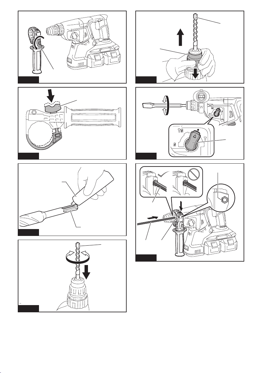
Fig.16
1
2
1
Fig.20
1
1
Fig.17
Fig.18
Fig.19
Fig.21
3
2
4
1
1
12
Fig.22
4
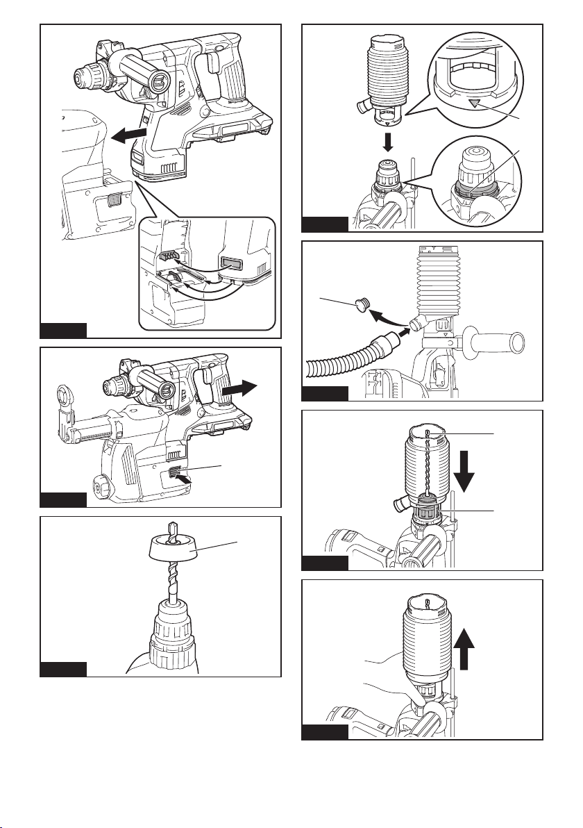
Fig.23
1
2
Fig.26
1
Fig.27
1
1
Fig.24
Fig.25
2
1
Fig.28
Fig.29
5
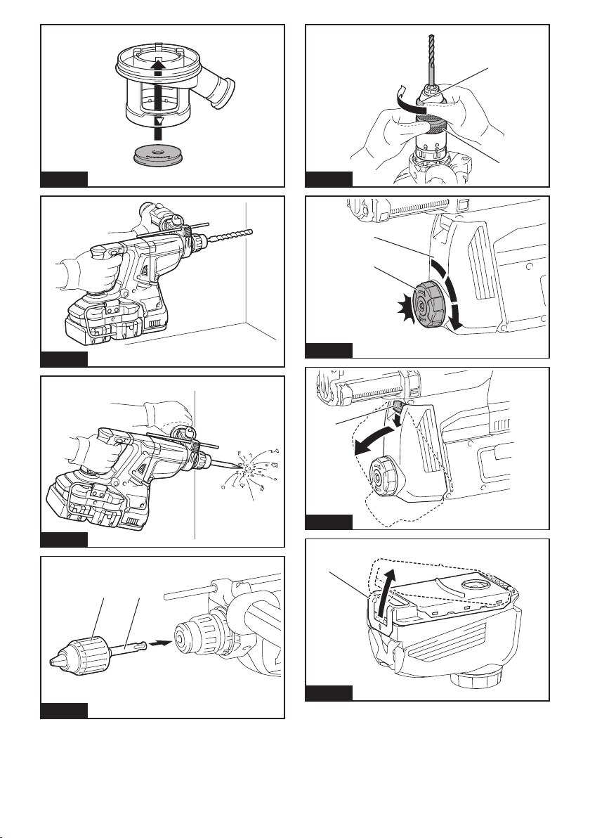
Fig.30
1
2
Fig.34
1
2
Fig.31
Fig.32
Fig.33
Fig.35
1
Fig.36
1
2
1
Fig.37
6
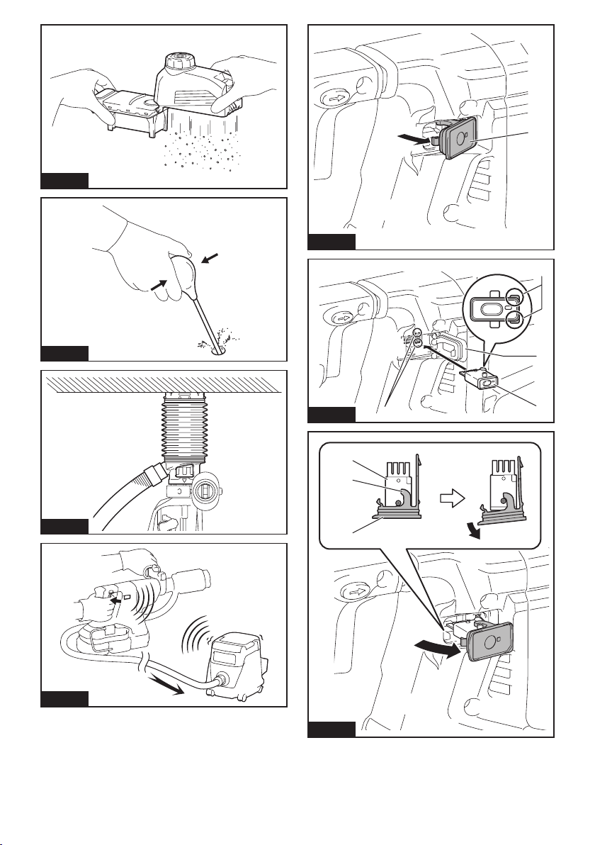
Fig.38
1
Fig.42
2
Fig.39
Fig.40
Fig.41
Fig.43
Fig.44
3
4
1
1
2
3
7
1
1
Fig.45
Fig.46
Fig.48
1 2
1 2
1 2
Fig.49
1
Fig.47
Fig.50
8
2
Fig.51
1 2
1
1 2
1
Fig.54
1
2
Fig.55
1
2
Fig.52
Fig.53
Fig.56
1
9

ENGLISH (Original instructions)
SPECIFICATIONS
Model: DHR280 DHR281 DHR282 DHR283
Capacities Concrete 28 mm
Core bit 54 mm
Diamond core bit (dry type) 65 mm
Steel 13 mm
Wood 32 mm
No load speed 0 - 980 min
Blows per minute 0 - 5,000 min
Overall length 373 mm 404 mm 373 mm 404 mm
Rated voltage D.C. 36 V
Net weight 3.9 - 5.1 kg
Optional accessory
Model: DX08 (For DHR280/DHR282) DX09 (For DHR281/DHR283)
Suction performance 350 l/min
Operating stroke Up to 190 mm
Suitable drill bit Up to 260 mm
Rated voltage D.C. 18 V
Net weight 1.6 kg
•
Due to our continuing program of research and development, the specications herein are subject to change without notice.
• Specications and battery cartridge may differ from country to country.
• The weight may differ depending on the attachment(s), including the battery cartridge. The lightest and heaviest combination, according to EPTA-Procedure 01/2014, are shown in the table.
Applicable battery cartridge
BL1815N / BL1820 / BL1820B / BL1830 / BL1830B / BL1840 / BL1840B / BL1850 / BL1850B / BL1860B
• Some of the battery cartridges listed above may not be available depending on your region of residence.
WARNING: Only use the battery cartridges listed above. Use of any other battery cartridges may cause
injury and/or re.
Intended use
The tool is intended for hammer drilling and drilling in
brick, concrete and stone as well as for chiselling work.
It is also suitable for drilling without impact in wood,
metal, ceramic and plastic.
Noise
The typical A-weighted noise level determined according to EN60745-2-6:
Model DHR280
Sound pressure level (L
Sound power level (LWA) : 104 dB (A)
Uncertainty (K) : 3 dB(A)
Model DHR281
Sound pressure level (L
Sound power level (LWA) : 103 dB (A)
Uncertainty (K) : 3 dB(A)
Model DHR282
Sound pressure level (L
Sound power level (LWA) : 104 dB (A)
Uncertainty (K) : 3 dB(A)
) : 93 dB(A)
pA
) : 92 dB(A)
pA
) : 93 dB(A)
pA
Model DHR283
Sound pressure level (L
Sound power level (LWA) : 103 dB (A)
Uncertainty (K) : 3 dB(A)
Model DHR280 with DX08
Sound pressure level (L
Sound power level (LWA) : 103 dB (A)
Uncertainty (K) : 3 dB(A)
Model DHR281 with DX09
Sound pressure level (L
Sound power level (LWA) : 103 dB (A)
Uncertainty (K) : 3 dB(A)
Model DHR282 with DX08
Sound pressure level (L
Sound power level (LWA) : 103 dB (A)
Uncertainty (K) : 3 dB(A)
Model DHR283 with DX09
Sound pressure level (L
Sound power level (LWA) : 103 dB (A)
Uncertainty (K) : 3 dB(A)
10 ENGLISH
) : 92 dB(A)
pA
) : 92 dB(A)
pA
) : 92 dB(A)
pA
) : 92 dB(A)
pA
) : 92 dB(A)
pA
-1
-1
NOTE: The declared noise emission value(s) has
been measured in accordance with a standard test
method and may be used for comparing one tool with
another.
NOTE: The declared noise emission value(s)
may also be used in a preliminary assessment of
exposure.
WARNING: Wear ear protection.
WARNING: The noise emission during actual
use of the power tool can differ from the declared
value(s) depending on the ways in which the
tool is used especially what kind of workpiece is
processed.
WARNING: Be sure to identify safety mea-
sures to protect the operator that are based on an
estimation of exposure in the actual conditions of
use (taking account of all parts of the operating
cycle such as the times when the tool is switched
off and when it is running idle in addition to the
trigger time).
Vibration
The following table shows the vibration total value
(tri-axial vector sum) determined according to applicable standard.
Model DHR280
Work mode Vibration
Hammer
drilling into
concrete
(a
h, HD
Hammer
drilling into
concrete with
DX08 (a
Chiselling function with side
grip (a
Drilling into
metal (a
)
h, Cheq
h, HD
h, D
)
)
emission
9.0 m/s
8.0 m/s
)
8.5 m/s
2.5 m/s
Model DHR281
Work mode Vibration
Hammer
drilling into
concrete
(a
h, HD
Hammer
drilling into
concrete with
DX09 (a
Chiselling function with side
grip (a
Drilling into
metal (a
)
h, Cheq
h, HD
h, D
)
)
emission
9.5 m/s
8.0 m/s
)
9.0 m/s
2.5 m/s
2
2
2
2
2
2
2
2
Uncertainty (K)
2
1.5 m/s
2
1.5 m/s
2
1.5 m/s
2
1.5 m/s
Uncertainty (K)
2
1.5 m/s
2
1.5 m/s
2
1.5 m/s
2
1.5 m/s
Applicable
standard
EN60745-2-6
EN60745-2-6
EN60745-2-6
EN60745-2-1
Applicable
standard
EN60745-2-6
EN60745-2-6
EN60745-2-6
EN60745-2-1
Model DHR282
Work mode Vibration
Hammer
drilling into
concrete
(a
h, HD
Hammer
drilling into
concrete with
DX08 (a
Chiselling function with side
grip (a
Drilling into
metal (a
)
h, Cheq
h, HD
h, D
)
)
emission
9.0 m/s
8.0 m/s
)
8.0 m/s
2.5 m/s
2
2
2
2
Uncertainty (K)
2
1.5 m/s
2
1.5 m/s
2
1.5 m/s
2
1.5 m/s
Applicable
standard
EN60745-2-6
EN60745-2-6
EN60745-2-6
EN60745-2-1
Model DHR283
Work mode Vibration
Hammer
drilling into
concrete
(a
h, HD
Hammer
drilling into
concrete with
DX09 (a
Chiselling function with side
grip (a
Drilling into
metal (a
)
h, Cheq
h, HD
h, D
)
)
emission
9.5 m/s
8.0 m/s
)
8.5 m/s
2.5 m/s
2
2
2
2
Uncertainty (K)
2
1.5 m/s
2
1.5 m/s
2
1.5 m/s
2
1.5 m/s
Applicable
standard
EN60745-2-6
EN60745-2-6
EN60745-2-6
EN60745-2-1
NOTE: The declared vibration total value(s) has been
measured in accordance with a standard test method
and may be used for comparing one tool with another.
NOTE: The declared vibration total value(s) may also
be used in a preliminary assessment of exposure.
WARNING: The vibration emission during
actual use of the power tool can differ from the
declared value(s) depending on the ways in which
the tool is used especially what kind of workpiece
is processed.
WARNING: Be sure to identify safety mea-
sures to protect the operator that are based on an
estimation of exposure in the actual conditions of
use (taking account of all parts of the operating
cycle such as the times when the tool is switched
off and when it is running idle in addition to the
trigger time).
EC Declaration of Conformity
For European countries only
The EC declaration of conformity is included as Annex A
to this instruction manual.
11 ENGLISH

SAFETY WARNINGS
General power tool safety warnings
WARNING: Read all safety warnings, instruc-
tions, illustrations and specications provided
with this power tool. Failure to follow all instructions
listed below may result in electric shock, re and/or
serious injury.
Save all warnings and instructions for future reference.
The term "power tool" in the warnings refers to your
mains-operated (corded) power tool or battery-operated
(cordless) power tool.
CORDLESS ROTARY HAMMER
SAFETY WARNINGS
1. Wear ear protectors. Exposure to noise can
cause hearing loss.
2. Use auxiliary handle(s), if supplied with the
tool. Loss of control can cause personal injury.
3. Hold power tool by insulated gripping surfaces, when performing an operation where
the cutting accessory may contact hidden
wiring. Cutting accessory contacting a "live"
wire may make exposed metal parts of the power
tool "live" and could give the operator an electric
shock.
4. Wear a hard hat (safety helmet), safety glasses
and/or face shield. Ordinary eye or sun glasses
are NOT safety glasses. It is also highly recommended that you wear a dust mask and thickly
padded gloves.
5. Be sure the bit is secured in place before
operation.
6. Under normal operation, the tool is designed
to produce vibration. The screws can come
loose easily, causing a breakdown or accident.
Check tightness of screws carefully before
operation.
7. In cold weather or when the tool has not been
used for a long time, let the tool warm up for
a while by operating it under no load. This
will loosen up the lubrication. Without proper
warm-up, hammering operation is difcult.
8. Always be sure you have a rm footing. Be
sure no one is below when using the tool in
high locations.
9. Hold the tool rmly with both hands.
10. Keep hands away from moving parts.
11. Do not leave the tool running. Operate the tool
only when hand-held.
12. Do not point the tool at any one in the area
when operating. The bit could y out and
injure someone seriously.
13. Do not touch the bit, parts close to the bit, or
workpiece immediately after operation; they
may be extremely hot and could burn your
skin.
14. Some material contains chemicals which may
be toxic. Take caution to prevent dust inhalation and skin contact. Follow material supplier
safety data.
15. Always be sure that the tool is switched
off and the battery cartridge and the bit are
removed before handing the tool to other
person.
SAVE THESE INSTRUCTIONS.
WARNING: DO NOT let comfort or familiarity
with product (gained from repeated use) replace
strict adherence to safety rules for the subject
product. MISUSE or failure to follow the safety
rules stated in this instruction manual may cause
serious personal injury.
Important safety instructions for
battery cartridge
1.
Before using battery cartridge, read all instructions and cautionary markings on (1) battery
charger, (2) battery, and (3) product using battery.
2. Do not disassemble battery cartridge.
3. If operating time has become excessively
shorter, stop operating immediately. It may
result in a risk of overheating, possible burns
and even an explosion.
4. If electrolyte gets into your eyes, rinse them
out with clear water and seek medical attention right away. It may result in loss of your
eyesight.
5. Do not short the battery cartridge:
(1) Do not touch the terminals with any con-
ductive material.
(2) Avoid storing battery cartridge in a con-
tainer with other metal objects such as
nails, coins, etc.
(3) Do not expose battery cartridge to water
or rain.
A battery short can cause a large current
ow, overheating, possible burns and even a
breakdown.
6. Do not store the tool and battery cartridge in
locations where the temperature may reach or
exceed 50 °C (122 °F).
7. Do not incinerate the battery cartridge even if
it is severely damaged or is completely worn
out. The battery cartridge can explode in a re.
8. Be careful not to drop or strike battery.
9. Do not use a damaged battery.
10. The contained lithium-ion batteries are subject
to the Dangerous Goods Legislation requirements.
For commercial transports e.g. by third parties,
forwarding agents, special requirement on packaging and labeling must be observed.
For preparation of the item being shipped, consulting an expert for hazardous material is required.
Please also observe possibly more detailed
national regulations.
Tape or mask off open contacts and pack up the
battery in such a manner that it cannot move
around in the packaging.
12 ENGLISH

11. Follow your local regulations relating to disposal of battery.
12. Use the batteries only with the products
specied by Makita. Installing the batteries to
non-compliant products may result in a re, excessive heat, explosion, or leak of electrolyte.
SAVE THESE INSTRUCTIONS.
CAUTION: Only use genuine Makita batteries.
Use of non-genuine Makita batteries, or batteries that
have been altered, may result in the battery bursting
causing res, personal injury and damage. It will
also void the Makita warranty for the Makita tool and
charger.
Tips for maintaining maximum
battery life
1. Charge the battery cartridge before completely
discharged. Always stop tool operation and
charge the battery cartridge when you notice
less tool power.
2. Never recharge a fully charged battery cartridge. Overcharging shortens the battery
service life.
3. Charge the battery cartridge with room temperature at 10 °C - 40 °C (50 °F - 104 °F). Let
a hot battery cartridge cool down before
charging it.
4. Charge the battery cartridge if you do not use
it for a long period (more than six months).
Important safety instructions for
wireless unit
1. Do not disassemble or tamper with the wireless unit.
2. Keep the wireless unit away from young children. If accidentally swallowed, seek medical
attention immediately.
3. Use the wireless unit only with Makita tools.
4. Do not expose the wireless unit to rain or wet
conditions.
5. Do not use the wireless unit in places where
the temperature exceeds 50°C (122°F).
6. Do not operate the wireless unit in places
where medical instruments, such as heart
pace makers are near by.
7. Do not operate the wireless unit in places
where automated devices are near by. If oper-
ated, automated devices may develop malfunction
or error.
8. Do not operate the wireless unit in places
under high temperature or places where
static electricity or electrical noise could be
generated.
9. The wireless unit can produce electromagnetic
elds (EMF) but they are not harmful to the
user.
10. The wireless unit is an accurate instrument. Be
careful not to drop or strike the wireless unit.
11. Avoid touching the terminal of the wireless
unit with bare hands or metallic materials.
12. Always remove the battery on the product
when installing the wireless unit into it.
13. When opening the lid of the slot, avoid the
place where dust and water may come into the
slot. Always keep the inlet of the slot clean.
14. Always insert the wireless unit in the correct
direction.
15. Do not press the wireless activation button
on the wireless unit too hard and/or press the
button with an object with a sharp edge.
16. Always close the lid of the slot when
operating.
17. Do not remove the wireless unit from the slot
while the power is being supplied to the tool.
Doing so may cause a malfunction of the wireless
unit.
18. Do not remove the sticker on the wireless unit.
19. Do not put any sticker on the wireless unit.
20. Do not leave the wireless unit in a place where
static electricity or electrical noise could be
generated.
21. Do not leave the wireless unit in a place subject to high heat, such as a car sitting in the
sun.
22. Do not leave the wireless unit in a dusty or
powdery place or in a place corrosive gas
could be generated.
23. Sudden change of the temperature may bedew
the wireless unit. Do not use the wireless unit
until the dew is completely dried.
24. When cleaning the wireless unit, gently wipe
with a dry soft cloth. Do not use benzine, thinner, conductive grease or the like.
25. When storing the wireless unit, keep it in the
supplied case or a static-free container.
26. Do not insert any devices other than Makita
wireless unit into the slot on the tool.
27. Do not use the tool with the lid of the slot damaged. Water, dust, and dirt come into the slot may
cause malfunction.
28. Do not pull and/or twist the lid of the slot more
than necessary. Restore the lid if it comes off
from the tool.
29. Replace the lid of the slot if it is lost or
damaged.
SAVE THESE INSTRUCTIONS.
13 ENGLISH
FUNCTIONAL DESCRIPTION
CAUTION: Always be sure that the tool is
switched off and the battery cartridge is removed
before adjusting or checking function on the tool.
Installing or removing battery cartridge
CAUTION: Always switch off the tool before
installing or removing of the battery cartridge.
CAUTION: Hold the tool and the battery car-
tridge rmly when installing or removing battery
cartridge. Failure to hold the tool and the battery
cartridge rmly may cause them to slip off your hands
and result in damage to the tool and battery cartridge
and a personal injury.
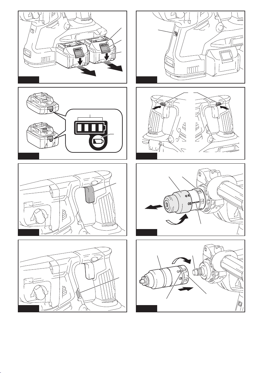
► Fig.1: 1. Red indicator 2. Button 3. Battery cartridge
To remove the battery cartridge, slide it from the tool
while sliding the button on the front of the cartridge.
To install the battery cartridge, align the tongue on the
battery cartridge with the groove in the housing and slip
it into place. Insert it all the way until it locks in place
with a little click. If you can see the red indicator on the
upper side of the button, it is not locked completely.
CAUTION: Always install the battery cartridge
fully until the red indicator cannot be seen. If not,
it may accidentally fall out of the tool, causing injury to
you or someone around you.
CAUTION: Do not install the battery cartridge
forcibly. If the cartridge does not slide in easily, it is
not being inserted correctly.
Indicating the remaining battery capacity
Only for battery cartridges with the indicator
► Fig.2: 1. Indicator lamps 2. Check button
Press the check button on the battery cartridge to indi-
cate the remaining battery capacity. The indicator lamps
light up for a few seconds.
Indicator lamps Remaining
Lighted Off Blinking
capacity
75% to 100%
50% to 75%
25% to 50%
0% to 25%
Charge the
battery.
The battery
may have
malfunctioned.
NOTE: Depending on the conditions of use and the
ambient temperature, the indication may differ slightly
from the actual capacity.
Tool / battery protection system
The tool is equipped with a tool/battery protection system. This system automatically cuts off power to the
motor to extend tool and battery life. The tool will automatically stop during operation if the tool or battery is
placed under one of the following conditions:
Overload protection
When the battery is operated in a manner that causes
it to draw an abnormally high current, the tool automatically stops without any indication. In this situation, turn
the tool off and stop the application that caused the tool
to become overloaded. Then turn the tool on to restart.
Overheat protection
When the tool or battery is overheated, the tool stops
automatically. In this case, let the tool and battery cool
before turning the tool on again.
NOTE: When the tool is overheated, the lamp blinks.
Overdischarge protection
When the battery capacity is not enough, the tool stops
automatically. In this case, remove the battery from the
tool and charge the battery.
Switch action
WARNING: Before installing the battery car-
tridge into the tool, always check to see that the
switch trigger actuates properly and returns to
the "OFF" position when released.
► Fig.3: 1. Switch trigger
To start the tool, simply pull the switch trigger. Tool
speed is increased by increasing pressure on the switch
trigger. Release the switch trigger to stop.
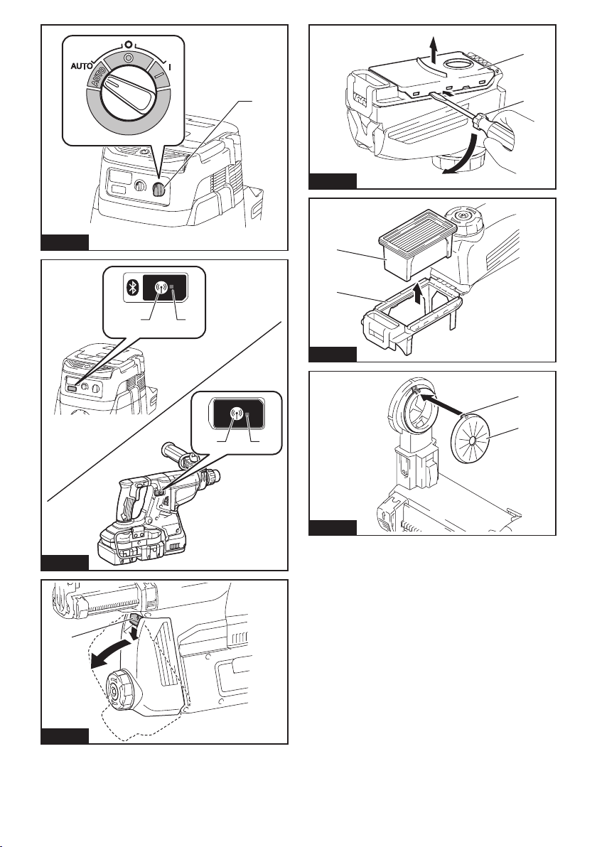
Speed change
The revolutions and blows per minute can be adjusted
by turning the adjusting dial. The dial is marked 1 (low-
est speed) to 5 (full speed).
► Fig.4: 1. Adjusting dial
Refer to the table below for the relationship between the
number on the adjusting dial and the revolutions and
blows per minute.
Number Revolutions per
5 980 5,000
4 810 4,130
3 640 3,260
2 470 2,400
1 300 1,550
minute
Blows per minute
14 ENGLISH
CAUTION: Do not turn the adjusting dial when
the tool is running. Failure to do so may result in
the loss of control of the tool and cause an injury.
NOTICE: If the tool is operated continuously at
low speed for a long time, the motor will get overloaded, resulting in tool malfunction.
NOTICE: The speed adjusting dial can be turned
only as far as 5 and back to 1. Do not force it past
5 or 1, or the speed adjusting function may no
longer work.
NOTE: Soft no-load rotation function (For
DHR282/DHR283)
When the speed adjusting dial is set to "3" or higher, the
tool automatically reduces the speed at no-load to reduce
the vibration under no-load. Once operation starts with
a bit against concrete, blows per minute increase and
reach the numbers as shown in the table. When tem-
perature is low and there is less uidity in grease, the tool
may not have this function even with the motor rotating.
This function is not available when the dust collection
system is installed.
Lighting up the front lamp
► Fig.5: 1. Lamp
CAUTION: Do not look in the light or see the
source of light directly.
Pull the switch trigger to light up the lamp. The lamp
keeps on lighting while the switch trigger is being pulled.
The lamp goes out approximately 10 seconds after
releasing the switch trigger.
CAUTION: For DHR282/DHR283
If the lamp goes off after blinking for a few seconds,
the active feedback sensing technology or the soft
no-load rotation function is not working properly.
Ask your local Makita Service Center for repair.
NOTE: Use a dry cloth to wipe the dirt off the lens of
the lamp. Be careful not to scratch the lens of lamp, or
it may lower the illumination.
NOTE: If the dust collection system is installed on the
tool, the lamp of the dust collection system lights up
instead of the lamp of the tool.
Reversing switch action
► Fig.6: 1. Reversing switch lever
CAUTION: Always check the direction of
rotation before operation.
CAUTION: Use the reversing switch only after
the tool comes to a complete stop. Changing the
direction of rotation before the tool stops may damage the tool.
CAUTION: When not operating the tool,
always set the reversing switch lever to the neutral position.
This tool has a reversing switch to change the direction
of rotation. Depress the reversing switch lever from the
A side for clockwise rotation or from the B side for counterclockwise rotation.
When the reversing switch lever is in the neutral position, the switch trigger cannot be pulled.
Changing the quick change chuck
for SDS-plus
For DHR281/DHR283
The quick change chuck for SDS-plus can be easily
exchanged for the quick change drill chuck.
Removing the quick change chuck
for SDS-plus
CAUTION: Before removing the quick change
chuck for SDS-plus, be sure to remove the bit.
Grasp the change cover of the quick change chuck for
SDS-plus and turn in the direction of the arrow until
the change cover line moves from the symbol to
the symbol. Pull forcefully in the direction of the arrow.
► Fig.7: 1. Quick change chuck for SDS-plus
2. Change cover 3. Change cover line
Installing the quick change drill chuck
Check the line of the quick change drill chuck shows
the symbol. Grasp the change cover of the quick
change drill chuck and set the line to the symbol.
Place the quick change drill chuck on the spindle of the
tool. Grasp the change cover of the quick change drill
chuck and turn the change cover line to the symbol
until a click can clearly be heard.
► Fig.8: 1. Quick change drill chuck 2. Spindle
3. Change cover line 4. Change cover
Selecting the action mode
NOTICE: Do not rotate the action mode chang-
ing knob when the tool is running. The tool will be
damaged.
NOTICE: To avoid rapid wear on the mode
change mechanism, be sure that the action mode
changing knob is always positively located in one
of the three action mode positions.
Rotation with hammering
For drilling in concrete, masonry, etc., rotate the action
mode changing knob to the symbol. Use a tungsten-
carbide tipped bit (optional accessory).
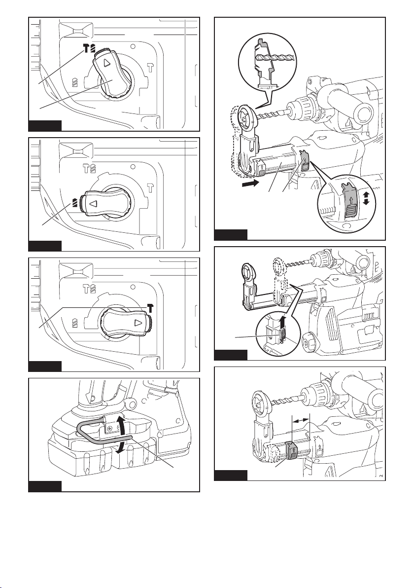
► Fig.9: 1. Rotation with hammering 2. Action mode
changing knob
Rotation only
For drilling in wood, metal or plastic materials, rotate
the action mode changing knob to the symbol. Use a
twist drill bit or wood drill bit.
► Fig.10: 1. Rotation only
15 ENGLISH

Hammering only
For chipping, scaling or demolition operations, rotate
the action mode changing knob to the symbol. Use a
bull point, cold chisel, scaling chisel, etc.
► Fig.11: 1. Hammering only
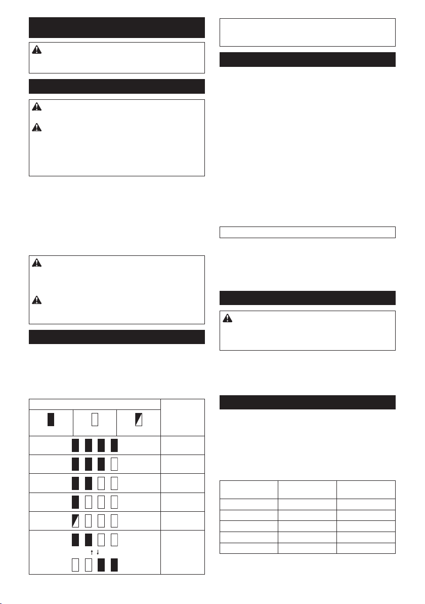
Hook
CAUTION: Never hook the tool at high loca-
tion or on potentially unstable surface.
► Fig.12: 1. Hook
The hook is convenient for temporarily hanging the tool.
To use the hook, simply lift up hook until it snaps into
the open position. When not in use, always lower hook
until it snaps into the closed position.
Adjusting the nozzle position of the
dust collection system
Optional accessory
Push in the guide while pushing up the guide adjustment button, and then release the button at the desired
position.
► Fig.13: 1. Guide 2. Guide adjustment button
NOTE: Before adjusting the nozzle position, release
the nozzle forward completely by pushing up the
guide adjustment button.
If a long drill bit is installed, extend the guide by pushing
up the extension button.
► Fig.14: 1. Extension button
Adjusting the drilling depth of the
dust collection system
Optional accessory
Slide the depth adjustment button to the desired position while pushing it up. The distance (A) is the drilling
depth.
► Fig.15: 1. Depth adjustment button
Torque limiter
NOTICE: As soon as the torque limiter actuates,
switch off the tool immediately. This will help pre-
vent premature wear of the tool.
NOTICE: Drill bits such as hole saw, which tend
to pinch or catch easily in the hole, are not appropriate for this tool. This is because they will cause
the torque limiter to actuate too frequently.
The torque limiter will actuate when a certain torque
level is reached. The motor will disengage from the
output shaft. When this happens, the drill bit will stop
turning.
Electronic function
The tool is equipped with the electronic functions for
easy operation.
• Constant speed control
The speed control function provides the constant
rotation speed regardless of load conditions.
• Active Feedback sensing Technology (For
DHR282/DHR283)
If the tool is swung at the predetermined acceleration during operation, the motor is forcibly stopped
to reduce the burden on the wrist.
NOTE:
This function does not work if the acceleration does
not reach the predetermined one when the tool is swung.
NOTE:
If the bit is swung at the predetermined acceleration during chipping, scaling, or demolishing, the motor
is forcibly stopped. In this case, release the switch trigger, and then pull the switch trigger to restart the tool.
ASSEMBLY
CAUTION: Always be sure that the tool is
switched off and the battery cartridge is removed
before carrying out any work on the tool.
Side grip (auxiliary handle)
CAUTION: Always use the side grip to ensure
safe operation.
CAUTION:
grip, make sure that the side grip is rmly secured.
To install the side grip, follow the steps below.
1. Loosen the thumb screw on the side grip.
► Fig.16: 1. Thumb screw
2. Attach the side grip while pressing the thumb
screw so that the grooves on the grip t in the protrusions on the tool barrel.
► Fig.17: 1. Thumb screw
3. Tighten the thumb screw to secure the grip. The
grip can be xed at desired angle.
Grease
Coat the shank end of the drill bit beforehand with a
small amount of grease (about 0.5 - 1 g).
This chuck lubrication assures smooth action and longer service life.
Installing or removing drill bit
Clean the shank end of the drill bit and apply grease
before installing the drill bit.
► Fig.18: 1. Shank end 2. Grease
Insert the drill bit into the tool. Turn the drill bit and push
it in until it engages.
After installing the drill bit, always make sure that the
drill bit is securely held in place by trying to pull it out.
► Fig.19: 1. Drill bit
16 ENGLISH
After installing or adjusting the side
To remove the drill bit, pull the chuck cover down all the
way and pull the drill bit out.
► Fig.20: 1. Drill bit 2. Chuck cover
Chisel angle (when chipping,
scaling or demolishing)
The chisel can be secured at the desired angle. To
change the chisel angle, rotate the action mode changing knob to the O symbol. Turn the chisel to the desired
angle.
► Fig.21: 1. Action mode changing knob
Rotate the action mode changing knob to the
bol. Then make sure that the chisel is securely held in
place by turning it slightly.
sym-
Depth gauge
The depth gauge is convenient for drilling holes of
uniform depth.
Press and hold the lock button, and then insert the
depth gauge into the hex hole. Make sure that the
toothed side of the depth gauge faces the marking.
► Fig.22: 1. Depth gauge 2. Lock button 3. Marking
Adjust the depth gauge by moving it back and forth
while pressing the lock button. After the adjustment,
release the lock button to lock the depth gauge.
NOTE: Make sure that the depth gauge does not
touch the main body of the tool when attaching it.
4. Toothed side
Installing or removing the dust
collection system
Optional accessory
To install the dust collection system, insert the tool into
the dust collection system all the way until it locks in
place with a little double click.
► Fig.23
To remove the dust collection system, pull the tool while
pressing the lock-off button.
► Fig.24: 1. Lock-off button
Dust cup
Optional accessory
Use the dust cup to prevent dust from falling over the
tool and on yourself when performing overhead drilling
operations. Attach the dust cup to the bit as shown in
the gure. The size of bits which the dust cup can be
attached to is as follows.
Model Bit diameter
Dust cup 5 6 mm - 14.5 mm
Dust cup 9 12 mm - 16 mm
► Fig.25: 1. Dust cup
Dust cup set
Optional accessory
Before installing the dust cup set, remove the bit from
the tool if installed.
Install the dust cup set on the tool so that the
bol on the dust cup is aligned with the groove in the tool.
► Fig.26: 1. symbol 2. Groove
NOTE: If you connect a vacuum cleaner to the dust
cup set, remove the dust cap before connecting it.
► Fig.27: 1. Dust cap
To remove the dust cup set, remove the bit while pulling
the chuck cover in the direction of the arrow.
► Fig.28: 1. Bit 2. Chuck cover
Hold the root of dust cup and pull it out.
► Fig.29
NOTE: If the cap comes off from the dust cup, attach
it with its printed side facing up so that groove on the
cap ts in the inside periphery of the attachment.
► Fig.30
OPERATION
CAUTION: Always use the side grip (auxiliary
handle) and rmly hold the tool by both side grip
and switch handle during operations.
CAUTION: Always make sure that the work-
piece is secured before operation.
CAUTION:
the bit gets stuck. Loss of control may cause injury.
CAUTION:
intended for drilling in concrete only. Do not use the
dust collection system for drilling in metal or wood.
CAUTION:
collection system, be sure to attach the lter to the
dust collection system to prevent dust inhalation.
CAUTION: Before using the dust collection
system, check that the lter is not damaged.
Failure to do so may cause dust inhalation.
CAUTION: The dust collection system col-
lects the generated dust at a considerable rate,
but not all dust can be collected.
NOTICE: Do not use the dust collection system
for core drilling or chiseling.
NOTICE:
drilling in wet concrete or use this system in wet environment. Failure to do so may cause malfunction.
NOTE: If the battery cartridge is in low temperature,
the tool’s capability may not be fully obtained. In this
case, warm up the battery cartridge by using the
tool with no load for a while to fully obtain the tool’s
capability.
► Fig.31
17 ENGLISH
Do not pull the tool out forcibly even
The dust collection system is
When using the tool with the dust
Do not use the dust collection system for
sym-
Hammer drilling operation
CAUTION: There is tremendous and sudden
twisting force exerted on the tool/drill bit at the time of
hole break-through, when the hole becomes clogged
with chips and particles, or when striking reinforcing
rods embedded in the concrete. Always use the side
grip (auxiliary handle) and rmly hold the tool by
both side grip and switch handle during operations. Failure to do so may result in the loss of control
of the tool and potentially severe injury.
Set the action mode changing knob to the symbol.
Position the drill bit at the desired location for the hole,
then pull the switch trigger. Do not force the tool. Light
pressure gives best results. Keep the tool in position
and prevent it from slipping away from the hole.
Do not apply more pressure when the hole becomes
clogged with chips or particles. Instead, run the tool at
an idle, then remove the drill bit partially from the hole.
By repeating this several times, the hole will be cleaned
out and normal drilling may be resumed.
NOTE: Eccentricity in the drill bit rotation may occur
while operating the tool with no load. The tool automatically centers itself during operation. This does not
affect the drilling precision.
Chipping/Scaling/Demolition
Set the action mode changing knob to the symbol.
Hold the tool rmly with both hands. Turn the tool on
and apply slight pressure on the tool so that the tool will
not bounce around, uncontrolled.
Pressing very hard on the tool will not increase the
efciency.
► Fig.32
Drilling in wood or metal
CAUTION: Hold the tool rmly and exert care
when the drill bit begins to break through the
workpiece. There is a tremendous force exerted on
the tool/drill bit at the time of hole break through.
CAUTION: A stuck drill bit can be removed
simply by setting the reversing switch to reverse
rotation in order to back out. However, the tool
may back out abruptly if you do not hold it rmly.
CAUTION: Always secure workpieces in a
vise or similar hold-down device.
NOTICE: Never use “rotation with hammering”
when the drill chuck is installed on the tool. The
drill chuck may be damaged.
Also, the drill chuck will come off when reversing the
tool.
NOTICE: Pressing excessively on the tool will
not speed up the drilling. In fact, this excessive
pressure will only serve to damage the tip of your drill
bit, decrease the tool performance and shorten the
service life of the tool.
Set the action mode changing knob to the symbol.
For DHR280/DHR282
Optional accessory
Attach the chuck adapter to a keyless drill chuck to
which 1/2"-20 size screw can be installed, and then
install them to the tool. When installing it, refer to the
section “Installing or removing drill bit”.
► Fig.33: 1. Keyless drill chuck 2. Chuck adapter
For DHR281/DHR283
Use the quick change drill chuck as standard equipment. When installing it, refer to "changing the quick
change chuck for SDS-plus".
Hold the ring and turn the sleeve counterclockwise to
open the chuck jaws. Place the bit in the chuck as far as
it will go. Hold the ring rmly and turn the sleeve clock-
wise to tighten the chuck.
► Fig.34: 1. Sleeve 2. Ring
To remove the bit, hold the ring and turn the sleeve
counterclockwise.
Diamond core drilling
NOTICE: If performing diamond core drilling
operations using “rotation with hammering”
action, the diamond core bit may be damaged.
When performing diamond core drilling operations,
always set the change lever to the position to use
"rotation only" action.
Beating dust on the lter
Optional accessory
CAUTION: Do not turn the dial on the dust
case while the dust case is removed from the
dust collection system. Doing so may cause dust
inhalation.
CAUTION: Always switch off the tool when
turning the dial on the dust case. Turning the dial
while the tool is running may result in the loss of
control of the tool.
By beating the dust on the lter inside the dust case,
you can keep the vacuum efciency and also reduce
the number of times to dispose of the dust.
Turn the dial on the dust case three times after collecting every 50,000 mm3 of dust or when you feel the
vacuum performance declined.
NOTE: 50,000 mm
holes of ø10 mm and 65 mm depth (14 holes of ø3/8″
and 2″ depth).
► Fig.35: 1. Dust case 2. Dial
3
of dust equivalents to drilling 10
18 ENGLISH
Disposing of dust
Optional accessory
CAUTION: Always be sure that the tool is
switched off and the battery cartridge is removed
before carrying out any work on the tool.
CAUTION: Be sure to wear dust mask when
disposing of dust.
CAUTION: Empty the dust case regularly
before the dust case becomes full. Failure to do so
may decrease the dust collection performance and
cause dust inhalation.
CAUTION: The performance of dust collection
decreases if the lter in the dust case become
clogged. Replace the lter with new one after
approximately 200 times of dust fulllment as a
guide. Failure to do so may cause dust inhalation.
1. Remove the dust case while pressing down the
lever of the dust case.
► Fig.36: 1. Lever
2. Open the cover of the dust case.
► Fig.37: 1. Cover
3. Dispose of the dust, and then clean the lter.
► Fig.38
NOTICE: When cleaning the lter, do not touch
the lter with brush or similar, or blow compressed air on the lter. It may damage the lter.
Blow-out bulb
Optional accessory
After drilling the hole, use the blow-out bulb to clean the
dust out of the hole.
► Fig.39
Using dust cup set
Optional accessory
Fit the dust cup set against the ceiling when operating
the tool.
► Fig.40
NOTICE: Do not use the dust cup set when drill-
ing in metal or similar. It may damage the dust
cup set due to the heat produced by small metal
dust or similar.
NOTICE: Do not install or remove the dust cup
set with the drill bit installed in the tool. It may
damage the dust cup set and cause dust leak.
WIRELESS ACTIVATION
FUNCTION
Optional accessory for DHR282/DHR283
What you can do with the wireless
activation function
The wireless activation function enables clean and comfortable operation. By connecting a supported vacuum
cleaner to the tool, you can run the vacuum cleaner
automatically along with the switch operation of the tool.
► Fig.41
To use the wireless activation function, prepare following items:
• A wireless unit (optional accessory)
• A vacuum cleaner which supports the wireless
activation function
The overview of the wireless activation function
setting is as follows. Refer to each section for detail
procedures.
1. Installing the wireless unit
2. Tool registration for the vacuum cleaner
3. Starting the wireless activation function
Installing the wireless unit
Optional accessory
CAUTION: Place the tool on a at and stable
surface when installing the wireless unit.
NOTICE: Clean the dust and dirt on the tool
before installing the wireless unit. Dust or dirt
may cause malfunction if it comes into the slot of the
wireless unit.
NOTICE: To prevent the malfunction caused by
static, touch a static discharging material, such
as a metal part of the tool, before picking up the
wireless unit.
NOTICE: When installing the wireless unit,
always be sure that the wireless unit is inserted
in the correct direction and the lid is completely
closed.
1. Open the lid on the tool as shown in the gure.
► Fig.42: 1. Lid
2. Insert the wireless unit to the slot and then close
the lid.
When inserting the wireless unit, align the projections
with the recessed portions on the slot.
► Fig.43: 1. Wireless unit 2. Projection 3. Lid
4. Recessed portion
When removing the wireless unit, open the lid slowly.
The hooks on the back of the lid will lift the wireless unit
as you pull up the lid.
► Fig.44: 1. Wireless unit 2. Hook 3. Lid
After removing the wireless unit, keep it in the supplied
case or a static-free container.
19 ENGLISH

NOTICE: Always use the hooks on the back of
the lid when removing the wireless unit. If the
hooks do not catch the wireless unit, close the lid
completely and open it slowly again.
Tool registration for the vacuum
cleaner
NOTE: A Makita vacuum cleaner supporting the
wireless activation function is required for the tool
registration.
NOTE: Finish installing the wireless unit to the tool
before starting the tool registration.
NOTE: During the tool registration, do not pull the
switch trigger or turn on the power switch on the
vacuum cleaner.
NOTE: Refer to the instruction manual of the vacuum
cleaner, too.
If you wish to activate the vacuum cleaner along with
the switch operation of the tool, nish the tool registration beforehand.
Install the batteries to the vacuum cleaner and the tool.
1.
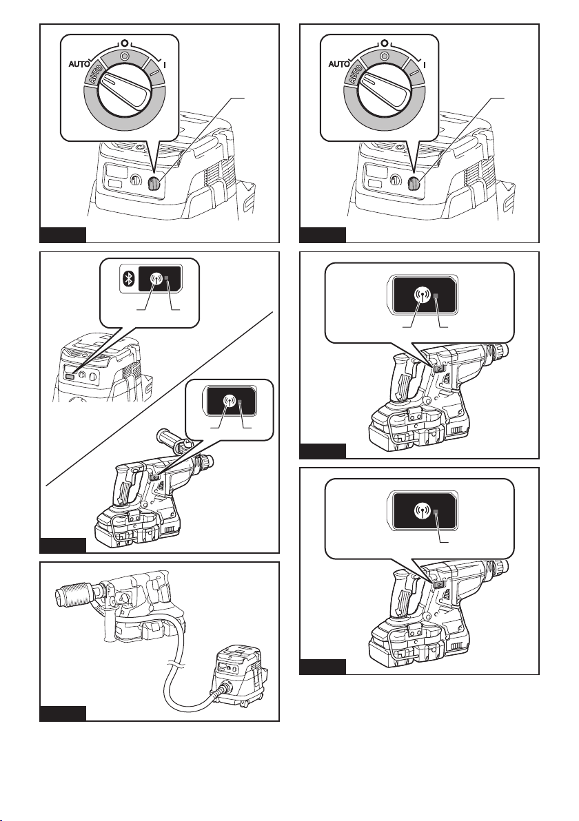
2. Set the stand-by switch on the vacuum cleaner to
"AUTO".
► Fig.45: 1. Stand-by switch
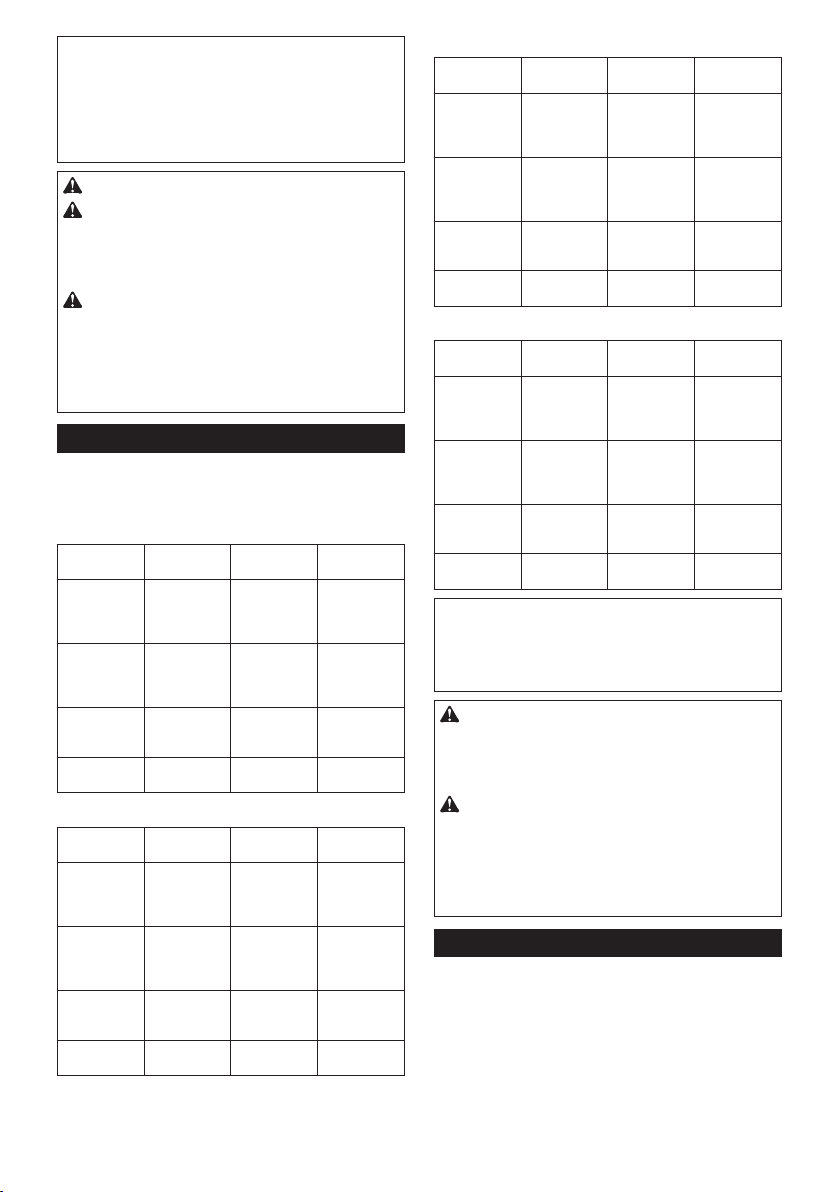
3. Press the wireless activation button on the vac-
uum cleaner for 3 seconds until the wireless activation
lamp blinks in green. And then press the wireless activation button on the tool in the same way.
► Fig.46: 1. Wireless activation button 2. Wireless
If the vacuum cleaner and the tool are linked successfully, the wireless activation lamps will light up in green
for 2 seconds and start blinking in blue.
NOTE: The wireless activation lamps nish blinking
in green after 20 seconds elapsed. Press the wireless
activation button on the tool while the wireless activation lamp on the cleaner is blinking. If the wireless
activation lamp does not blink in green, push the wire-
less activation button briey and hold it down again.
NOTE: When performing two or more tool registra-
tions for one vacuum cleaner, nish the tool registration one by one.
activation lamp
3. Set the stand-by switch on the vacuum cleaner to
"AUTO".
► Fig.48: 1. Stand-by switch
4. Push the wireless activation button on the tool
briey. The wireless activation lamp will blink in blue.
► Fig.49: 1. Wireless activation button 2. Wireless
activation lamp
5. Pull the switch trigger of the tool. Check if the
vacuum cleaner runs while the switch trigger is being
pulled.
To stop the wireless activation of the vacuum cleaner,
push the wireless activation button on the tool.
NOTE: The wireless activation lamp on the tool will
stop blinking in blue when there is no operation for
2 hours. In this case, set the stand-by switch on the
vacuum cleaner to "AUTO" and push the wireless
activation button on the tool again.
NOTE: The vacuum cleaner starts/stops with a delay.
There is a time lag when the vacuum cleaner detects
a switch operation of the tool.
NOTE: The transmission distance of the wireless unit
may vary depending on the location and surrounding
circumstances.
NOTE: When two or more tools are registered to one
vacuum cleaner, the vacuum cleaner may start running even if you don't pull the switch trigger because
an other user is using the wireless activation function.
Starting the wireless activation
function
NOTE: Finish the tool registration for the vacuum
cleaner prior to the wireless activation.
NOTE: Refer to the instruction manual of the vacuum
cleaner, too.
After registering a tool to the vacuum cleaner, the
vacuum cleaner will automatically runs along with the
switch operation of the tool.
1. Install the wireless unit to the tool.
Connect the hose of the vacuum cleaner with the tool.
2.
► Fig.47
20 ENGLISH
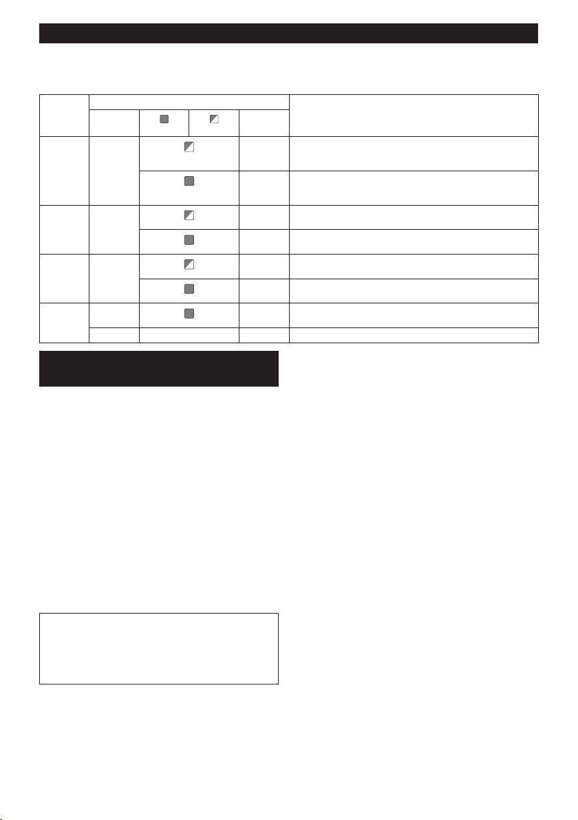
Description of the wireless activation lamp status
► Fig.50: 1. Wireless activation lamp
The wireless activation lamp shows the status of the wireless activation function. Refer to the table below for the
meaning of the lamp status.
Status Wireless activation lamp Description
Duration
2 hours The wireless activation of the vacuum cleaner is available. The
the tool is
running.
20 seconds Ready for the tool registration. Waiting for the registration by the
2 seconds The tool registration has been nished. The wireless activation
20 seconds Ready for the cancellation of the tool registration. Waiting for the
2 seconds The cancellation of the tool registration has been nished. The
3 seconds The power is supplied to the wireless unit and the wireless activa-
lamp will automatically turn off when no operation is performed
for 2 hours.
When
The wireless activation of the vacuum cleaner is available and the
tool is running.
vacuum cleaner.
lamp will start blinking in blue.
cancellation by the vacuum cleaner.
wireless activation lamp will start blinking in blue.
tion function is starting up.
Standby Blue
Tool
registration
Cancelling
tool
registration
Others Red
Color
Green
Red
Off - - The wireless activation of the vacuum cleaner is stopped.
On
Blinking
Cancelling tool registration for the
vacuum cleaner
Perform the following procedure when cancelling the
tool registration for the vacuum cleaner.
1. Install the batteries to the vacuum cleaner and the
tool.
2. Set the stand-by switch on the vacuum cleaner to
"AUTO".
► Fig.51: 1. Stand-by switch
3. Press the wireless activation button on the vac-
uum cleaner for 6 seconds. The wireless activation
lamp blinks in green and then become red. After that,
press the wireless activation button on the tool in the
same way.
► Fig.52: 1. Wireless activation button 2. Wireless
If the cancellation is performed successfully, the wireless activation lamps will light up in red for 2 seconds
and start blinking in blue.
NOTE: The wireless activation lamps nish blinking in
red after 20 seconds elapsed. Press the wireless activation button on the tool while the wireless activation
lamp on the cleaner is blinking. If the wireless activation lamp does not blink in red, push the wireless
activation button briey and hold it down again.
activation lamp
21 ENGLISH

Troubleshooting for wireless activation function
Before asking for repairs, conduct your own inspection rst. If you nd a problem that is not explained in the manual,
do not attempt to dismantle the tool. Instead, ask Makita Authorized Service Centers, always using Makita replacement parts for repairs.
State of abnormality Probable cause (malfunction) Remedy
The wireless activation lamp does
not light/blink.
Cannot nish tool registration / cancelling tool registration successfully.
The vacuum cleaner does not run
along with the switch operation of
the tool.
The vacuum cleaner runs while the
tool's switch trigger is not pulled.
The wireless unit is not installed into the tool.
The wireless unit is improperly installed
into the tool.
The terminal of the wireless unit and/or
the slot is dirty.
The wireless activation button on the
tool has not been pushed.
The stand-by switch on the vacuum
cleaner is not set to "AUTO".
No power supply
The wireless unit is not installed into the tool.
The wireless unit is improperly installed
into the tool.
The terminal of the wireless unit and/or
the slot is dirty.
The stand-by switch on the vacuum
cleaner is not set to "AUTO".
No power supply
Incorrect operation
The tool and vacuum cleaner are away
from each other (out of the transmission
range).
Before nishing the tool registration/
cancellation;
- the switch trigger on the tool is pulled or;
- the power button on the vacuum
cleaner is turned on.
The tool registration procedures for the
tool or vacuum cleaner has not nished.
Radio disturbance by other appliances
which generate high-intensity radio
waves.
The wireless unit is not installed into the tool.
The wireless unit is improperly installed
into the tool.
The terminal of the wireless unit and/or
the slot is dirty.
The wireless activation button on the
tool has not been pushed.
The stand-by switch on the vacuum
cleaner is not set to "AUTO".
More than 10 tools are registered to the
vacuum cleaner.
The vacuum cleaner erased all tool
registrations.
No power supply Supply the power to the tool and the vacuum
The tool and vacuum cleaner are away
from each other (out of the transmission
range).
Radio disturbance by other appliances
which generate high-intensity radio waves.
Other users are using the wireless
activation of the vacuum cleaner with
their tools.
Install the wireless unit correctly.
Gently wipe off dust and dirt on the terminal of the
wireless unit and clean the slot.
Push the wireless activation button on the tool
briey.
Set the stand-by switch on the vacuum cleaner to
"AUTO".
Supply the power to the tool and the vacuum cleaner.
Install the wireless unit correctly.
Gently wipe off dust and dirt on the terminal of the
wireless unit and clean the slot.
Set the stand-by switch on the vacuum cleaner to
"AUTO".
Supply the power to the tool and the vacuum cleaner.
Push the wireless activation button briey and perform
the tool registration/cancellation procedures again.
Get the tool and vacuum cleaner closer to each other.
The maximum transmission distance is approximately 10
m however it may vary according to the circumstances.
Push the wireless activation button briey and
perform the tool registration/cancellation procedures
again.
Perform the tool registration procedures for both the
tool and the vacuum cleaner at the same timing.
Keep the tool and vacuum cleaner away from the
appliances such as Wi-Fi devices and microwave
ovens.
Install the wireless unit correctly.
Gently wipe off dust and dirt on the terminal of the
wireless unit and clean the slot.
Push the wireless activation button briey and make
sure that the wireless activation lamp is blinking in blue.
Set the stand-by switch on the vacuum cleaner to
"AUTO".
Perform the tool registration again.
If more than 10 tools are registered to the vacuum cleaner,
the tool registered earliest will be cancelled automatically.
Perform the tool registration again.
cleaner.
Get the tool and vacuum cleaner closer each other. The
maximum transmission distance is approximately 10 m
however it may vary according to the circumstances.
Keep the tool and vacuum cleaner away from the appliances such as Wi-Fi devices and microwave ovens.
Turn off the wireless activation button of the other
tools or cancel the tool registration of the other
tools.
22 ENGLISH

MAINTENANCE
CAUTION: Always be sure that the tool is
switched off and the battery cartridge is removed
before attempting to perform inspection or
maintenance.
NOTICE: Never use gasoline, benzine, thinner,
alcohol or the like. Discoloration, deformation or
cracks may result.
To maintain product SAFETY and RELIABILITY,
repairs, any other maintenance or adjustment should
be performed by Makita Authorized or Factory Service
Centers, always using Makita replacement parts.
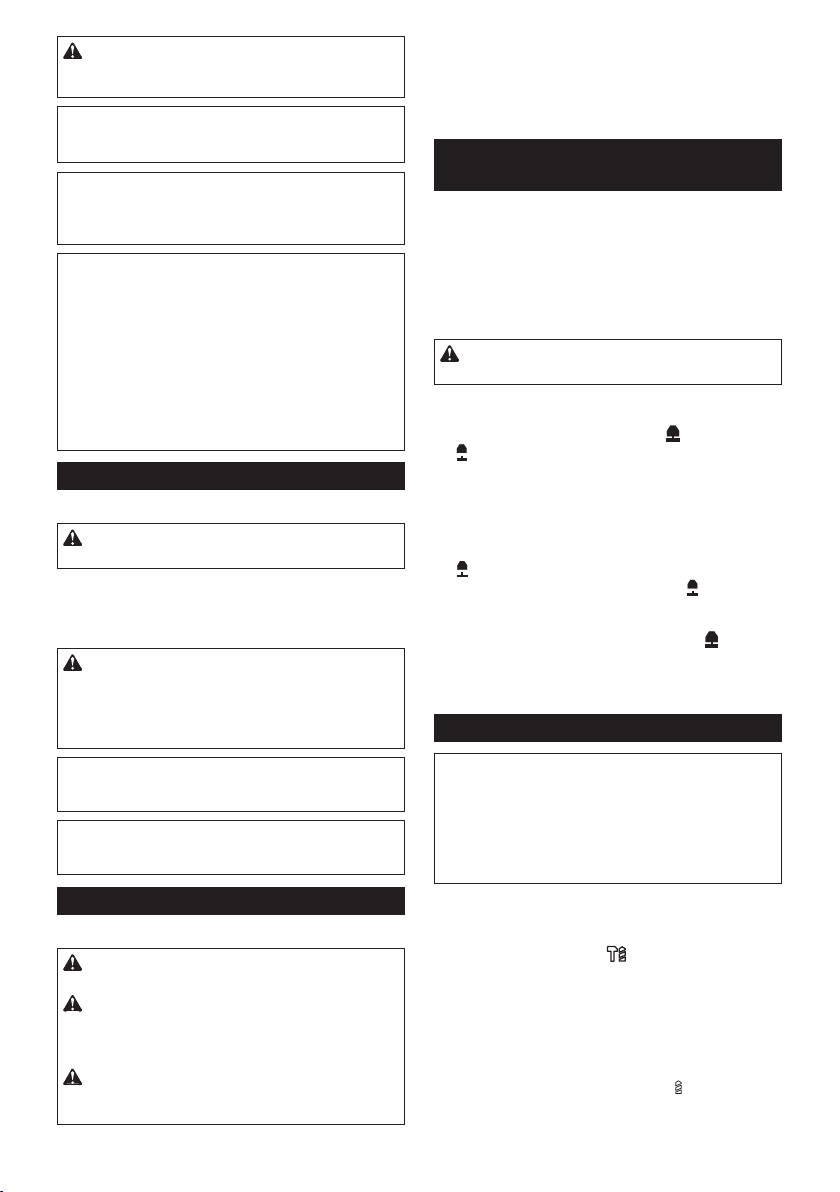
Replacing lter of dust case
Optional accessory
1. Remove the dust case while pressing down the
lever of the dust case.
► Fig.53: 1. Lever
2. Insert the at-blade screwdriver into the slots of
the lter cover to remove the lter cover.
► Fig.54: 1. Flat-blade screwdriver 2. Filter cover
3. Remove the lter from the lter case.
► Fig.55: 1. Filter 2. Filter case
4. Attach a new lter to the lter case, and then
attach the lter cover.
5. Close the cover of the dust case, and then attach
the dust case to the dust collection system.
Replacing sealing cap
Optional accessory
If the sealing cap is worn out, the performance of the
dust collection decreases. Replace it if it's worn out.
Remove the sealing cap, and then attach a new one
with its protrusion facing upward.
► Fig.56: 1. Protrusion 2. Sealing cap
• Grooving chisel
• Chuck adapter
• Keyless drill chuck
• Bit grease
• Depth gauge
• Blow-out bulb
• Dust cup
• Dust cup set
• Dust collection system
• Wireless unit
• Makita genuine battery and charger
• Safety goggles
• Plastic carrying case
NOTE: Some items in the list may be included in the
tool package as standard accessories. They may
differ from country to country.
OPTIONAL ACCESSORIES
CAUTION: These accessories or attachments
are recommended for use with your Makita tool
specied in this manual. The use of any other
accessories or attachments might present a risk of
injury to persons. Only use accessory or attachment
for its stated purpose.
If you need any assistance for more details regarding
these accessories, ask your local Makita Service Center.
• Carbide-tipped drill bits (SDS-Plus carbide-tipped
bits)
• Core bit
• Bull point
• Diamond core bit
• Cold chisel
• Scaling chisel
23 ENGLISH

FRANÇAIS (Instructions originales)
SPÉCIFICATIONS
Modèle : DHR280 DHR281 DHR282 DHR283
Capacités Béton 28 mm
Trépan 54 mm
Trépan diamant (type sec) 65 mm
Acier 13 mm
Bois 32 mm
Vitesse à vide 0 - 980 min
Frappes par minute 0 - 5 000 min
Longueur totale 373 mm 404 mm 373 mm 404 mm
Tension nominale 36 V CC
Poids net 3,9 - 5,1 kg
Accessoire en option
Modèle :
Performance d’aspiration 350 l/min
Course de travail Jusqu’à 190 mm
Foret adéquat Jusqu’à 260 mm
Tension nominale 18 V CC
Poids net 1,6 kg
DX08 (Pour le DHR280/DHR282) DX09 (Pour le DHR281/DHR283)
• Étant donné l’évolution constante de notre programme de recherche et de développement, les spécications
contenues dans ce manuel sont sujettes à modication sans préavis.
• Les spécications et la batterie peuvent être différentes suivant les pays.
• Le poids peut être différent selon les accessoires, notamment la batterie. Les associations la plus légère et la
plus lourde, conformément à la procédure EPTA 01/2014, sont indiquées dans le tableau.
Batterie applicable
BL1815N / BL1820 / BL1820B / BL1830 / BL1830B / BL1840 / BL1840B / BL1850 / BL1850B / BL1860B
• Certaines batteries répertoriées ci-dessus peuvent ne pas être disponibles selon la région où vous résidez.
AVERTISSEMENT : N’utilisez que les batteries répertoriées ci-dessus. L’utilisation de n’importe quelle
autre batterie peut provoquer des blessures et/ou un incendie.
Utilisation prévue
L’outil est conçu pour le perçage avec martelage et le perçage dans la
brique, le béton et la pierre, ainsi que pour les tâches de ciselage.
Il convient également au perçage sans impact dans le
bois, le métal, la céramique et le plastique.
Bruit
Niveau de bruit pondéré A typique, déterminé selon EN60745-2-6 :
Modèle DHR280
Niveau de pression sonore (LpA) : 93 dB (A)
Niveau de puissance sonore (L
Incertitude (K) : 3 dB (A)
Modèle DHR281
Niveau de pression sonore (L
Niveau de puissance sonore (L
Incertitude (K) : 3 dB (A)
Modèle DHR282
Niveau de pression sonore (L
Niveau de puissance sonore (L
Incertitude (K) : 3 dB (A)
) : 104 dB (A)
WA
) : 92 dB (A)
pA
) : 103 dB (A)
WA
) : 93 dB (A)
pA
) : 104 dB (A)
WA
Modèle DHR283
Niveau de pression sonore (L
Niveau de puissance sonore (L
Incertitude (K) : 3 dB (A)
Modèle DHR280 avec DX08
Niveau de pression sonore (L
Niveau de puissance sonore (L
Incertitude (K) : 3 dB (A)
Modèle DHR281 avec DX09
Niveau de pression sonore (L
Niveau de puissance sonore (L
Incertitude (K) : 3 dB (A)
Modèle DHR282 avec DX08
Niveau de pression sonore (L
Niveau de puissance sonore (LWA) : 103 dB (A)
Incertitude (K) : 3 dB (A)
Modèle DHR283 avec DX09
Niveau de pression sonore (L
Niveau de puissance sonore (LWA) : 103 dB (A)
Incertitude (K) : 3 dB (A)
24 FRANÇAIS
-1
-1
) : 92 dB (A)
pA
) : 103 dB (A)
WA
) : 92 dB (A)
pA
) : 103 dB (A)
WA
) : 92 dB (A)
pA
) : 103 dB (A)
WA
) : 92 dB (A)
pA
) : 92 dB (A)
pA

NOTE : La ou les valeurs d’émission de bruit déclarées ont été mesurées conformément à la méthode
de test standard et peuvent être utilisées pour comparer les outils entre eux.
NOTE : La ou les valeurs d’émission de bruit décla-
rées peuvent aussi être utilisées pour l’évaluation
préliminaire de l’exposition.
AVERTISSEMENT :
Portez un serre-tête antibruit.
AVERTISSEMENT : L’émission de bruit
lors de l’usage réel de l’outil électrique peut être
différente de la ou des valeurs déclarées, suivant
la façon dont l’outil est utilisé, particulièrement
selon le type de pièce usinée.
AVERTISSEMENT :
Les mesures de sécurité à
prendre pour protéger l’utilisateur doivent être basées
sur une estimation de l’exposition dans des conditions réelles d’utilisation (en tenant compte de toutes
les composantes du cycle d’utilisation, comme par
exemple le moment de sa mise hors tension, lorsqu’il
tourne à vide et le moment de son déclenchement).
Vibrations
Le tableau suivant indique la valeur totale de vibrations (somme
de vecteur triaxial) déterminée selon la norme applicable.
Modèle DHR280
Mode de
travail
Perçage avec
martelage
dans le béton
(a
h, HD
Perçage avec
martelage
dans le béton
avec le DX08
(a
h, HD
Fonction de
ciselage avec
poignée laté
rale (a
Perçage dans
le métal (a
Modèle DHR281
Mode de
travail
Perçage avec
martelage
dans le béton
(a
h, HD
Perçage avec
martelage
dans le béton
avec le DX09
(a
h, HD
Fonction de
ciselage avec
poignée latérale (a
Perçage dans
le métal (a
)
)
h, Cheq
)
)
h, Cheq
-
)
)
h, D
)
)
h, D
Émission de
vibrations
2
9,0 m/s
2
8,0 m/s
2
8,5 m/s
2
2,5 m/s
Émission de
vibrations
2
9,5 m/s
2
8,0 m/s
2
9,0 m/s
2
2,5 m/s
Incertitude (K)
2
1,5 m/s
2
1,5 m/s
2
1,5 m/s
2
1,5 m/s
Incertitude (K)
2
1,5 m/s
2
1,5 m/s
2
1,5 m/s
2
1,5 m/s
Norme
applicable
EN60745-2-6
EN60745-2-6
EN60745-2-6
EN60745-2-1
Norme
applicable
EN60745-2-6
EN60745-2-6
EN60745-2-6
EN60745-2-1
Modèle DHR282
Mode de
travail
Perçage avec
martelage
dans le béton
(a
h, HD
Perçage avec
martelage
dans le béton
avec le DX08
(a
h, HD
Fonction de
ciselage avec
poignée latérale (a
Perçage dans
le métal (a
)
)
h, Cheq
)
)
h, D
Émission de
vibrations
2
9,0 m/s
2
8,0 m/s
2
8,0 m/s
2
2,5 m/s
Incertitude (K)
2
1,5 m/s
2
1,5 m/s
2
1,5 m/s
2
1,5 m/s
Norme
applicable
EN60745-2-6
EN60745-2-6
EN60745-2-6
EN60745-2-1
Modèle DHR283
Mode de
travail
Perçage avec
martelage
dans le béton
(a
h, HD
Perçage avec
martelage
dans le béton
avec le DX09
(a
h, HD
Fonction de
ciselage avec
poignée latérale (a
Perçage dans
le métal (a
)
)
h, Cheq
)
)
h, D
Émission de
vibrations
2
9,5 m/s
2
8,0 m/s
2
8,5 m/s
2
2,5 m/s
Incertitude (K)
2
1,5 m/s
2
1,5 m/s
2
1,5 m/s
2
1,5 m/s
Norme
applicable
EN60745-2-6
EN60745-2-6
EN60745-2-6
EN60745-2-1
NOTE : La ou les valeurs de vibration totales déclarées ont été mesurées conformément à la méthode
de test standard et peuvent être utilisées pour comparer les outils entre eux.
NOTE : La ou les valeurs de vibration totales décla-
rées peuvent aussi être utilisées pour l’évaluation
préliminaire de l’exposition.
AVERTISSEMENT : L’émission de vibrations
lors de l’usage réel de l’outil électrique peut être
différente de la ou des valeurs déclarées, suivant
la façon dont l’outil est utilisé, particulièrement
selon le type de pièce usinée.
AVERTISSEMENT : Les mesures de sécurité
à prendre pour protéger l’utilisateur doivent être
basées sur une estimation de l’exposition dans
des conditions réelles d’utilisation (en tenant
compte de toutes les composantes du cycle
d’utilisation, comme par exemple le moment de
sa mise hors tension, lorsqu’il tourne à vide et le
moment de son déclenchement).
Déclaration de conformité CE
Pour les pays européens uniquement
La déclaration de conformité CE est fournie en Annexe
A à ce mode d’emploi.
25 FRANÇAIS

CONSIGNES DE SÉCURITÉ
Consignes de sécurité générales
pour outils électriques
AVERTISSEMENT : Veuillez lire les
consignes de sécurité, instructions, illustrations
et spécications qui accompagnent cet outil
électrique. Le non-respect de toutes les instructions
indiquées ci-dessous peut entraîner une électrocution, un incendie et/ou de graves blessures.
Conservez toutes les mises en
garde et instructions pour référence ultérieure.
Le terme « outil électrique » dans les avertissements
fait référence à l’outil électrique alimenté par le secteur
(avec cordon d’alimentation) ou à l’outil électrique fonctionnant sur batterie (sans cordon d’alimentation).
CONSIGNES DE SÉCURITÉ POUR
PERFORATEUR SANS FIL
1. Portez des protecteurs d’oreilles. L’exposition
au bruit peut entraîner la surdité.
2. Utilisez la ou les poignées auxiliaires, si l’outil
en possède. Toute perte de maîtrise de l’outil
comporte un risque de blessure.
3.
Tenez l’outil électrique par des surfaces de prise
isolées lorsque vous effectuez une tâche au cours
de laquelle l’accessoire de coupe peut entrer en
contact avec des ls cachés. Le contact de l’acces-
soire de découpe avec un l sous tension peut transmettre du courant dans les pièces métalliques expo-
sées de l’outil électrique et électrocuter l’utilisateur.
4.
Portez un casque de sécurité (casque de chantier), des lunettes de sécurité et/ou un écran
facial. Les lunettes de vue ou les lunettes de
soleil NE sont PAS des lunettes de sécurité. Il est
également vivement recommandé de porter un
masque anti-poussière et des gants matelassés.
5. Avant utilisation, assurez-vous que le foret est
bien xé en place.
6.
Dans des conditions normales de fonctionnement,
l’outil est conçu pour émettre des vibrations. Les
vis peuvent se desserrer facilement et provoquer
une panne ou un accident. Avant utilisation, véri-
ez soigneusement que les vis sont bien serrées.
7.
Par temps froid ou si l’outil n’a pas été utilisé
pendant longtemps, laissez-le chauffer un instant
en le faisant fonctionner à vide. Cela ramollira le
lubriant. Si vous ne chauffez pas adéquatement
l’outil, le martelage s’exécutera difcilement.
8.
Assurez-vous toujours de travailler en position
stable. Veillez à ce que personne ne se trouve en dessous de vous quand vous utilisez l’outil en hauteur.
9. Tenez l’outil fermement à deux mains.
10. Éloignez les mains des pièces en mouvement.
11. Ne vous éloignez pas en laissant l’outil tour-
ner. Ne le faites fonctionner que lorsque vous
l’avez bien en main.
12. Ne pointez l’outil vers personne dans la zone
d’utilisation. Le foret peut être projeté et blesser gravement quelqu’un.
13. Ne touchez pas le foret, les pièces proches du
foret ou la pièce immédiatement après l’exécution du travail ; ils peuvent être extrêmement
chauds et vous brûler la peau.
14. Certains matériaux contiennent des produits
chimiques qui peuvent être toxiques. Prenez
garde de ne pas avaler la poussière et évitez
tout contact avec la peau. Suivez les données
de sécurité du fournisseur du matériau.
15. Assurez-vous toujours que l’outil est hors
tension et que la batterie et le foret sont retirés
avant de passer l’outil à une autre personne.
CONSERVEZ CES INSTRUCTIONS.
AVERTISSEMENT :
(au l d’une utilisation répétée) par un sentiment d’aisance
et de familiarité avec le produit, en négligeant le respect
rigoureux des consignes de sécurité qui accompagnent le
produit en question. La MAUVAISE UTILISATION de l’outil
ou l’ignorance des consignes de sécurité indiquées dans
ce mode d’emploi peut entraîner de graves blessures.
Consignes de sécurité importantes
pour la batterie
1. Avant d’utiliser la batterie, lisez toutes les
instructions et précautions relatives (1) au
chargeur de batterie, (2) à la batterie, et (3) au
produit utilisant la batterie.
2. Ne démontez pas la batterie.
3.
Cessez immédiatement l’utilisation si le temps de
fonctionnement devient excessivement court. Il y a
risque de surchauffe, de brûlures, voire d’explosion.
4.
Si l’électrolyte pénètre dans vos yeux, rincez-les
à l’eau claire et consultez immédiatement un
médecin. Il y a risque de perte de la vue.
5. Ne court-circuitez pas la batterie :
(1) Ne touchez les bornes avec aucun maté-
riau conducteur.
(2)
Évitez de ranger la batterie dans un conteneur
avec d’autres objets métalliques, par exemple
des clous, des pièces de monnaie, etc.
(3)
N’exposez pas la batterie à l’eau ou à la pluie.
Un court-circuit de la batterie peut provoquer
une intensité de courant élevée, une surchauffe,
parfois des brûlures et même une panne.
6. Ne rangez pas l’outil et la batterie dans un
endroit où la température risque d’atteindre ou
de dépasser 50 °C.
7.
Ne jetez pas la batterie au feu même si elle est
sérieusement endommagée ou complètement épuisée. La batterie peut exploser au contact du feu.
8.
Évitez de laisser tomber ou de cogner la batterie.
9.
N’utilisez pas la batterie si elle est endommagée.
10. Les batteries au lithium-ion contenues sont
soumises aux exigences de la législation sur
les marchandises dangereuses.
Lors du transport commercial par des tierces
parties ou des transitaires par exemple, des exi-
gences spéciques en matière d’étiquetage et
d’emballage doivent être respectées.
26 FRANÇAIS
NE vous laissez PAS tromper

Pour la préparation de l’article expédié, il est nécessaire de consulter un expert en matériau dangereux.
Veuillez également respecter les réglementations
nationales susceptibles d’être plus détaillées.
Recouvrez les contacts exposés avec du ruban
adhésif ou du ruban de masquage et emballez la
batterie de telle sorte qu’elle ne puisse pas bouger
dans l’emballage.
11. Suivez les réglementations locales en matière
de mise au rebut des batteries.
12. Utilisez les batteries uniquement avec les
produits spéciés par Makita. L’insertion de
batteries dans des produits non conformes peut
provoquer un incendie, une chaleur excessive,
une explosion ou une fuite de l’électrolyte.
CONSERVEZ CES INSTRUCTIONS.
ATTENTION :
d’origine. L’utilisation de batteries de marque autre que
Makita ou de batteries modiées peut provoquer l’explosion des batteries, ce qui présente un risque d’incendie,
de dommages matériels et corporels. Cela annulera également la garantie Makita pour l’outil et le chargeur Makita.
N’utilisez que des batteries Makita
Conseils pour assurer la durée
de vie optimale de la batterie
1. Chargez la batterie avant qu’elle ne soit complètement déchargée. Arrêtez toujours l’outil
et rechargez la batterie quand vous remarquez
que la puissance de l’outil diminue.
2. Ne rechargez jamais une batterie complètement chargée. La surcharge réduit la durée de
service de la batterie.
3.
Chargez la batterie à une température ambiante
comprise entre 10 °C et 40 °C. Avant de charger
une batterie chaude, laissez-la refroidir.
4.
Rechargez la batterie si elle est restée inutilisée
pendant une période prolongée (plus de six mois).
Consignes de sécurité importantes
pour le connecteur sans l
1.
Ne démontez ni ne modiez le connecteur sans l.
2.
Conservez le connecteur sans l hors de portée
des jeunes enfants. En cas d’ingestion accidentelle, consultez immédiatement un médecin.
3. Utilisez le connecteur sans l uniquement
avec des outils Makita.
4. N’exposez pas le connecteur sans l à la pluie
ou à l’humidité.
5. N’utilisez pas le connecteur sans l dans un
endroit où la température dépasse 50 °C.
6.
Ne faites pas fonctionner le connecteur sans
l dans un endroit où des appareils médicaux
comme des simulateurs cardiaques sont utilisés.
7.
Ne faites pas fonctionner le connecteur sans l
dans un endroit où des appareils automatiques
sont utilisés. Sinon, ces appareils pourraient
présenter un dysfonctionnement ou une erreur.
8. N’utilisez pas le connecteur sans l dans
un endroit à température élevée ou dans un
endroit susceptible de générer de l’électricité
statique ou du bruit électrique.
9.
Le connecteur sans l peut produire des champs
électromagnétiques (CEM), mais ceux-ci ne sont
pas dangereux pour l’utilisateur.
10. Le connecteur sans l est un instrument de
précision. Évitez de laisser tomber ou de
cogner le connecteur sans l.
11. Évitez de toucher la borne du connecteur sans
l avec les mains nues ou avec des objets
métalliques.
12. Retirez toujours la batterie du produit avant
d’y installer le connecteur sans l.
13. Évitez d’ouvrir le couvercle de la fente dans un
endroit où de la poussière ou de l’eau pourrait
pénétrer dans la fente. Maintenez toujours
propre l’entrée de la fente.
14. Insérez toujours le connecteur sans l dans le
bon sens.
15. N’appuyez pas trop fort sur le bouton d’activation sans l du connecteur sans l, ni n’appuyez dessus avec un objet pointu.
16. Fermez toujours le couvercle de la fente pendant le fonctionnement.
17. Ne retirez pas le connecteur sans l de la
fente alors que l’outil est sous tension. Vous
risqueriez de provoquer un dysfonctionnement du
connecteur sans l.
18.
Ne retirez pas l’autocollant du connecteur sans l.
19. Ne placez pas d’autocollant sur le connecteur
sans l.
20. Ne laissez pas le connecteur sans l dans un
endroit susceptible de générer de l’électricité
statique ou du bruit électrique.
21. Ne laissez pas le connecteur sans l dans un
endroit soumis à une forte chaleur, comme
une voiture en plein soleil.
22. Ne laissez pas le connecteur sans l dans un
endroit poussiéreux ou sablonneux ou dans
un endroit susceptible de générer des gaz
corrosifs.
23. De la condensation peut se former sur le
connecteur sans l en cas de brusque changement de température. N’utilisez pas le connec-
teur sans l tant que la condensation n’a pas
complètement séché.
24. Pour nettoyer le connecteur sans l,
essuyez-le délicatement avec un chiffon doux
et sec. N’utilisez pas de benzine, diluant,
graisse conductrice ou autre.
25. Rangez le connecteur sans l en le conser-
vant dans l’étui fourni ou dans un récipient
anti-statique.
26.
N’insérez pas d’autres dispositifs que le connec-
teur sans l Makita dans la fente sur l’outil.
27. N’utilisez pas l’outil si le couvercle de la fente
est endommagé. L’eau, la poussière ou la saleté
pourraient pénétrer dans la fente provoquant un
dysfonctionnement.
28. Ne tirez, ni ne tordez plus que nécessaire le
couvercle de la fente. Remettez le couvercle en
place s’il se détache de l’outil.
29. Remplacez le couvercle de la fente si vous le
perdez ou l’endommagez.
CONSERVEZ CES INSTRUCTIONS.
27 FRANÇAIS
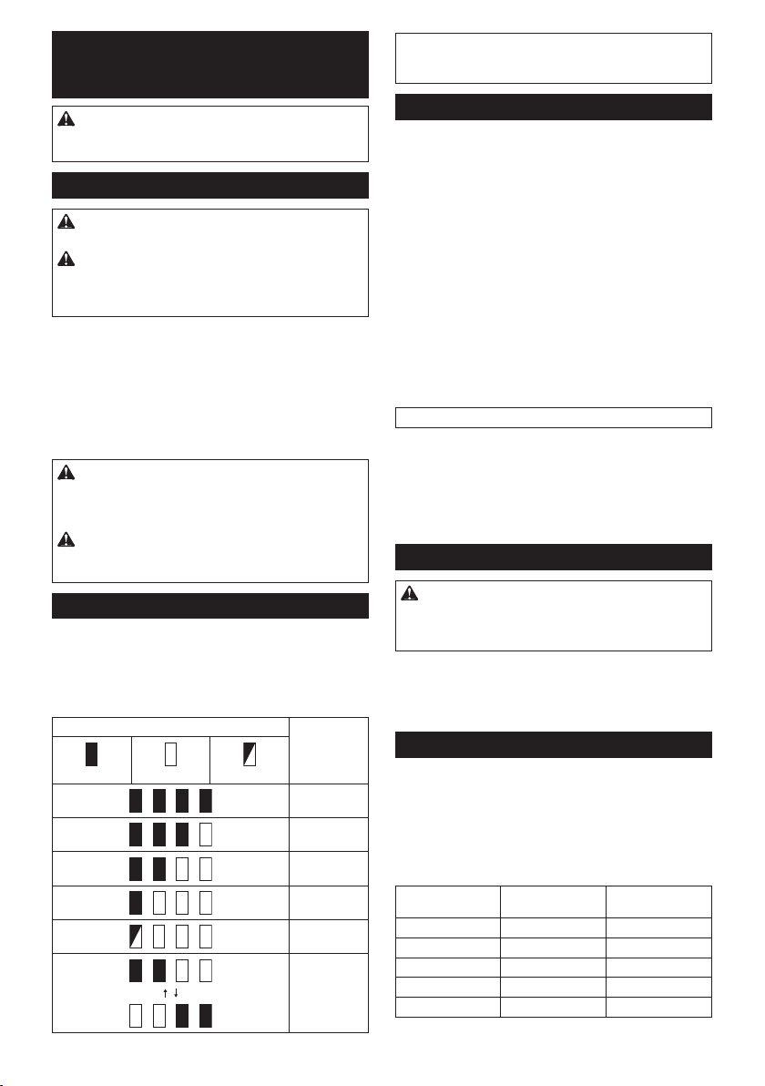
DESCRIPTION DU
FONCTIONNEMENT
ATTENTION :
est hors tension et que sa batterie est retirée avant
de l’ajuster ou de vérier son fonctionnement.
Insertion ou retrait de la batterie
ATTENTION : Éteignez toujours l’outil avant
de mettre en place ou de retirer la batterie.
ATTENTION :
rie lors de la mise en place ou du retrait de la batterie. Si
vous ne tenez pas fermement l’outil et la batterie, ils peuvent
vous glisser des mains, et s’abîmer ou vous blesser.
► Fig.1: 1. Voyant rouge 2. Bouton 3. Batterie
Pour retirer la batterie, faites-la glisser hors de l’outil
tout en faisant glisser le bouton à l’avant de la batterie.
Pour mettre en place la batterie, alignez la languette sur la
batterie avec la rainure sur le compartiment et insérez-la.
Insérez-la à fond jusqu’à ce qu’un léger déclic se fasse
entendre. Si le voyant rouge sur le dessus du bouton est
visible, cela signie qu’elle n’est pas bien verrouillée.
ATTENTION :
batterie jusqu’à ce que le voyant rouge ne soit plus visible.
Sinon, elle pourrait tomber accidentellement de l’outil, au risque
de vous blesser ou de blesser quelqu’un se trouvant près de vous.
ATTENTION : N’insérez pas la batterie de
force. Si elle ne glisse pas facilement, c’est que vous
ne l’insérez pas correctement.
Indication de la charge restante de la batterie
Uniquement pour les batteries avec voyant lumineux
► Fig.2: 1. Témoins 2. Bouton de vérication
Appuyez sur le bouton de vérication sur la batterie
pour indiquer la charge restante de la batterie. Les
témoins s’allument pendant quelques secondes.
Allumé Éteint Clignotant
Assurez-vous toujours que l’outil
Tenez fermement l’outil et la batte-
Insérez toujours complètement la
Témoins Charge
restante
75 % à 100 %
50 % à 75 %
25 % à 50 %
0 % à 25 %
Chargez la
batterie.
Anomalie
possible
de la batterie.
NOTE : Selon les conditions d’utilisation et la tem-
pérature ambiante, l’indication peut être légèrement
différente de la capacité réelle.
Système de protection de l’outil/la batterie
L’outil est équipé d’un système de protection de l’outil/la batterie. Ce système coupe automatiquement l’alimentation vers le
moteur pour prolonger la durée de vie de l’outil et de la batterie. Si l’outil ou la batterie se trouve dans l’une des situations
suivantes, l’outil cessera automatiquement de fonctionner.
Protection contre la surcharge
Lorsque la batterie est utilisée d’une manière provoquant
un appel de courant anormalement élevé, l’outil s’arrête
automatiquement sans indication. Dans ce cas, éteignez
l’outil et arrêtez la tâche ayant provoqué la surcharge de
l’outil. Puis rallumez l’outil pour reprendre la tâche.
Protection contre la surchauffe
En cas de surchauffe de l’outil ou de la batterie, l’outil
s’arrête automatiquement. Dans ce cas, laissez l’outil et
la batterie refroidir avant de rallumer l’outil.
NOTE : Si l’outil surchauffe, la lampe clignote.
Protection contre la décharge totale
de la batterie
Lorsque la charge de la batterie est insufsante, l’outil
s’arrête automatiquement. Dans ce cas, retirez la batte-
rie de l’outil et chargez-la.
Fonctionnement de la gâchette
AVERTISSEMENT : Avant d’insérer la batte-
rie dans l’outil, vériez toujours que la gâchette
fonctionne bien et revient en position d’arrêt
lorsque vous la relâchez.
► Fig.3: 1. Gâchette
Il suft d’enclencher la gâchette pour démarrer l’outil. La vitesse
de l’outil augmente à mesure que l’on accroît la pression exer-
cée sur la gâchette. Pour l’arrêter, relâchez la gâchette.
Changement de vitesse
Les tours et frappes par minute peuvent être réglés en
tournant le cadran de réglage. Le cadran est marqué de
1 (vitesse la plus basse) à 5 (pleine vitesse).
► Fig.4: 1. Cadran de réglage
Reportez-vous au tableau ci-dessous pour le rapport
entre le numéro sur le cadran de réglage et les tours et
frappes par minute.
Numéro Tours par minute Frappes par
5 980 5 000
4 810 4 130
3 640 3 260
2 470 2 400
1 300 1 550
minute
28 FRANÇAIS
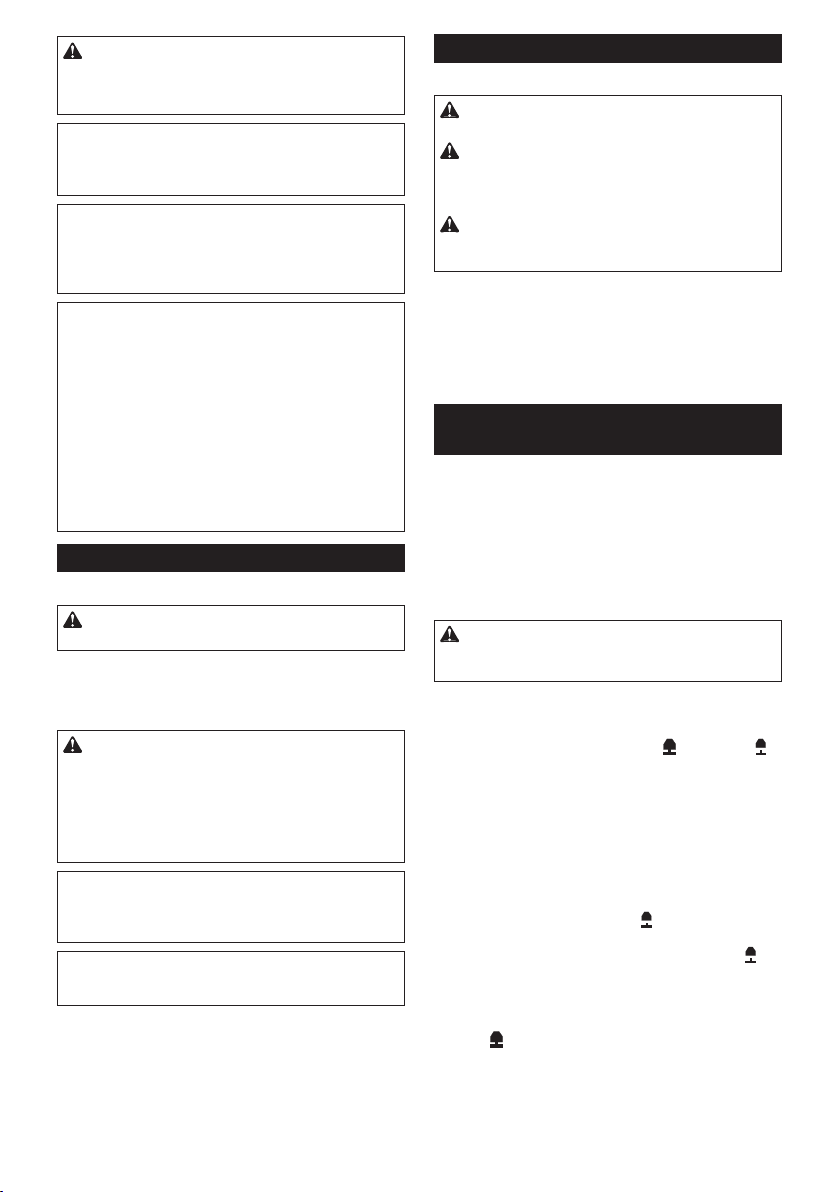
ATTENTION : Ne tournez pas le cadran de
réglage pendant que l’outil fonctionne. Si vous ne
suivez pas cette directive, vous risquez de perdre
la maîtrise de l’outil et de vous blesser.
REMARQUE : L’utilisation constante de l’outil
à une vitesse basse pendant un long moment
entraîne une surcharge du moteur, ce qui entraîne
un dysfonctionnement de l’outil.
REMARQUE : Le cadran de réglage de la vitesse
ne peut pas être tourné plus haut que 5 ou plus
bas que 1. N’essayez pas de le placer au-delà de 5
ou en dessous de 1, sinon la fonction de réglage
de la vitesse risque de ne plus fonctionner.
NOTE : Fonction de rotation en douceur à vide
(Pour le DHR282/DHR283)
Lorsque le cadran de réglage de la vitesse est réglé
sur « 3 » ou plus, l’outil réduit automatiquement
la vitesse à vide pour diminuer les vibrations sans
charge. Une fois que l’outil démarre avec un foret
contre du béton, les frappes par minute augmentent
pour atteindre les chiffres indiqués dans le tableau. Si
la température est basse et qu’il y a moins de uidité
dans la graisse, il se peut que l’outil n’ait pas cette
fonction même avec le moteur qui tourne.
Cette fonction n’est pas disponible lorsque le système
de collecte des poussières est installé.
Allumage de la lampe avant
► Fig.5: 1. Lampe
ATTENTION : Évitez de regarder directement
le faisceau lumineux ou sa source.
Enclenchez la gâchette pour allumer la lampe. La
lampe reste allumée tant que la gâchette est enclen-
chée. La lampe s’éteint environ 10 secondes après
avoir relâché la gâchette.
ATTENTION : Pour le DHR282/DHR283
Si la lampe s’éteint après avoir clignoté pendant
quelques secondes, la technologie de détection
de réaction active ou la fonction de rotation en
douceur à vide ne fonctionnera pas correctement.
Conez la réparation à votre centre de service
Makita.
NOTE : Retirez la saleté sur la lentille de la lampe
avec un chiffon sec. Prenez soin de ne pas éraer
la lentille de la lampe sous peine de diminuer son
éclairage.
NOTE : Si le système de collecte des poussières
est installé sur l’outil, sa lampe s’allume au lieu de la
lampe de l’outil.
Fonctionnement de l’inverseur
► Fig.6: 1. Levier de l’inverseur
ATTENTION : Vériez toujours le sens de
rotation avant d’utiliser l’outil.
ATTENTION : N’utilisez l’inverseur qu’une
fois que l’outil est complètement arrêté. Si vous
changez le sens de rotation avant l’arrêt de l’outil,
vous risquez de l’endommager.
ATTENTION : Lorsque vous n’utilisez pas
l’outil, placez toujours le levier de l’inverseur en
position neutre.
L’outil possède un inverseur qui permet de changer
le sens de rotation. Enfoncez le levier de l’inverseur
du côté A pour une rotation dans le sens des aiguilles
d’une montre, ou du côté B pour une rotation dans le
sens inverse des aiguilles d’une montre.
La gâchette ne peut pas être enclenchée lorsque le
levier de l’inverseur se trouve en position neutre.
Remplacement du mandrin de
remplacement rapide pour SDS-plus
Pour le DHR281/DHR283
Il est facile de remplacer le mandrin de remplacement
rapide pour SDS-plus par le mandrin à foret de remplacement rapide.
Retrait du mandrin de remplacement
rapide pour SDS-plus
ATTENTION : Avant de retirer le mandrin de
remplacement rapide pour SDS-plus, veillez à retirer
le foret.
Saisissez le couvercle de remplacement du mandrin de
remplacement rapide pour SDS-plus et tournez dans le
sens de la èche jusqu’à ce que la ligne du couvercle
de remplacement passe du symbole
Tirez fortement dans le sens de la èche.
► Fig.7: 1. Mandrin de remplacement rapide pour
SDS-plus 2. Couvercle de remplacement
3. Ligne du couvercle de remplacement
au symbole .
Installation du mandrin à foret de
remplacement rapide
Vériez que la ligne du mandrin à foret de remplacement rapide présente le symbole
vercle de remplacement du mandrin à foret de remplacement rapide et réglez la ligne sur le symbole .
Placez le mandrin à foret de remplacement rapide sur
l’axe de l’outil. Saisissez le couvercle de remplacement
du mandrin à foret de remplacement rapide et faites
tourner la ligne du couvercle de remplacement sur le
symbole jusqu’à ce qu’un clic se fasse clairement
entendre.
► Fig.8: 1. Mandrin à foret de remplacement rapide
2. Axe 3. Ligne du couvercle de remplace-
ment 4. Couvercle de remplacement
. Saisissez le cou-
29 FRANÇAIS
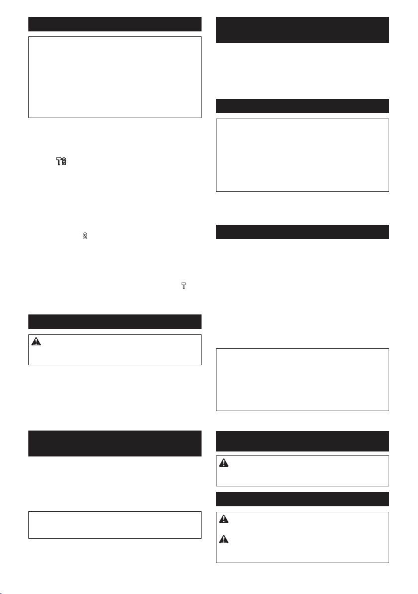
Sélection du mode de fonctionnement
REMARQUE : Ne tournez pas le bouton de
changement de mode pendant que l’outil fonctionne. L’outil serait endommagé.
REMARQUE : Pour éviter que le mécanisme
de changement de mode ne s’use rapidement,
vous devez toujours vous assurer que le bouton
de changement de mode est placé avec exactitude sur l’une des trois positions du mode de
fonctionnement.
Rotation avec martelage
Pour percer dans le béton, de la maçonnerie, etc.,
tournez le bouton de changement de mode jusqu’au
symbole . Utilisez un foret à pointe en carbure de
tungstène (accessoire en option).
► Fig.9: 1. Rotation avec martelage 2. Bouton de
changement de mode
Rotation uniquement
Pour percer dans le bois, le métal ou des matériaux en
plastique, tournez le bouton de changement de mode
jusqu’au symbole . Utilisez un foret hélicoïdal ou à bois.
► Fig.10: 1. Rotation uniquement
Martelage uniquement
Pour le burinage, l’écaillage ou la démolition, tournez le
bouton de changement de mode jusqu’au symbole .
Utilisez un pic, un ciseau à froid, un ciseau à écailler, etc.
► Fig.11: 1. Martelage uniquement
Crochet
ATTENTION : N’accrochez jamais l’outil dans
un emplacement élevé ou sur une surface potentiellement instable.
► Fig.12: 1. Crochet
Le crochet est pratique pour suspendre momentané-
ment l’outil.
Pour utiliser le crochet, il suft de le soulever jusqu’à ce
qu’il passe en position ouverte. Lorsque vous ne l’uti-
lisez pas, abaissez toujours le crochet jusqu’à ce qu’il
passe en position fermée.
Réglage de la position de la buse du
système de collecte des poussières
Accessoire en option
Appuyez sur le guide tout en poussant vers le haut le
bouton de réglage du guide, puis relâchez le bouton à
la position souhaitée.
► Fig.13: 1. Guide 2. Bouton de réglage du guide
NOTE : Avant de régler la position de la buse, relâ-
chez totalement la buse vers l’avant en poussant vers
le haut le bouton de réglage du guide.
Si un foret long est installé, déployez le guide en poussant vers le haut le bouton de déploiement.
► Fig.14: 1. Bouton de déploiement
Réglage de la profondeur de perçage du
système de collecte des poussières
Accessoire en option
Faites coulisser le bouton de réglage de la profondeur
jusqu’à la position souhaitée en le poussant vers le
haut. La distance (A) est la profondeur du perçage.
► Fig.15: 1. Bouton de réglage de la profondeur
Limiteur de couple
REMARQUE : Si le limiteur de couple se
déclenche, éteignez immédiatement l’outil. Ceci
permettra d’éviter l’usure prématurée de l’outil.
REMARQUE : Les forets, comme les scies clo-
ches qui ont tendance à se coincer ou se prendre
facilement dans le trou, ne sont pas appropriés
pour cet outil. Ils déclenchent trop fréquemment le
limiteur de couple.
Le limiteur de couple se déclenche lorsqu’un certain
niveau de couple est atteint. Le moteur se dégage de
l’arbre de sortie. Dans ce cas, le foret cesse de tourner.
Fonction électronique
L’outil est doté de fonctions électroniques pour en faciliter le fonctionnement.
• Contrôle de vitesse constante
La fonction de contrôle de la vitesse offre une
vitesse de rotation constante quelles que soient
les conditions de charge.
• Technologie de détection de réaction active (Pour
le DHR282/DHR283)
Si l’outil est animé d’un mouvement oscillant à
l’accélération prédéterminée pendant le fonc-
tionnement, le moteur sera forcé à s’arrêter pour
réduire la charge sur le poignet.
NOTE :
Cette fonction est inopérante si l’accélération n’atteint
pas celle prédéterminée lors du mouvement oscillant de l’outil.
NOTE : Si le foret est animé d’un mouvement
oscillant à l’accélération prédéterminée pendant le
burinage, l’écaillage ou la démolition, le moteur sera
forcé à s’arrêter. Dans ce cas, relâchez la gâchette,
puis enclenchez-la à nouveau pour redémarrer l’outil.
ASSEMBLAGE
ATTENTION : Assurez-vous toujours que
l’outil est hors tension et que sa batterie est retirée avant d’effectuer toute tâche dessus.
Poignée latérale (poignée auxiliaire)
ATTENTION : Utilisez toujours la poignée
latérale pour garantir votre sécurité.
ATTENTION : Après avoir mis en place ou
réglé la poignée latérale, assurez-vous qu’elle est
solidement xée.
30 FRANÇAIS
 Loading...