

Makita DC9711 Technical Information

T
ECHNICAL INFORMATION
Models No.
Description
DC9711
Charger
CONCEPTION AND MAIN APPLICATIONS
This charger can charge both Ni-Cd.and Ni-MH.batteries
of which powers are 7.2V and 9.6V.
Its brief benefits and features are as follows.
* The charging time is kept in the steady level by controlling the
out put current ( current for charging battery) in spite of the changeable
input voltage (power source voltage).
* The charger can switch into trickle charge (maintenance charge) mode
to keep the full charged condition for battery left in the charger.
Specification
H
W
Width ( W )
Height ( H )
Length ( L )
PRODUCT
P 1 / 2
L
Dimensions : mm ( " )
80 (3-1/8)
63 (2-1/2)
145 (5-3/4)
Voltage (V) Cycle (Hz)
220 - 240
230 - 240
Output voltage (D/C)
Output current (D/C)
Ni-Cd. battery 2.0Ah approx. 90 min.
Charging
time
Net weight : Kg ( lbs )
Cord length : m ( ft )
Current (A)
7.2 V, 9.6 V,
1.5 A
Ni-Cd. battery 1.3Ah
Ni-MH.battery 2.2Ah
Ni-MH.battery 2.6Ah
Ni-MH.battery 3.0Ah
0.41 (0.9)
2.0 (6.6)
50 / 60
50 / 60
approx. 60 min.
approx. 100 min.
approx. 115 min.
approx. 130 min.
Continuous Rating (W)
Input Output
35
35
The chargeable batteries
Voltage
7.2 V
9.6 V
Type No.
7000 (Ni-Cd. 1.3Ah)
7002 (Ni-Cd. 2.0Ah)
7033 (Ni-MH. 2.2Ah)
9000 (Ni-Cd. 1.3Ah)
9100 (Ni-Cd. 1.3Ah)
9120 (Ni-Cd. 1.3Ah)
9002 (Ni-Cd. 2.0Ah)
9102 (Ni-Cd. 2.0Ah)
9102A (Ni-Cd. 2.0Ah)
9122 (Ni-Cd. 2.0Ah)
9033 (Ni-MH. 2.2Ah)
9133 (Ni-MH. 2.2Ah)
9134 (Ni-MH. 2.6Ah)
9135 (Ni-MH. 3.0Ah)
Max. Output(W)
Charging time
approx. 60 min.
approx. 90 min.
approx. 100 min.
approx. 60 min.
approx. 60 min.
approx. 60 min.
approx. 90 min.
approx. 90 min.
approx. 90 min.
approx. 90 min.
approx. 100 min.
approx. 100 min.
approx. 115 min.
approx. 130 min.
Repair
<1> The circuit board can not be repaired, because the circuit itself are molded on the board
with the urethane resin.
It has to be replaced completely with new one.
<2> In case of damaged varistor or fuse, they can be repaired according to the following procedure without
replacing the circuit board.
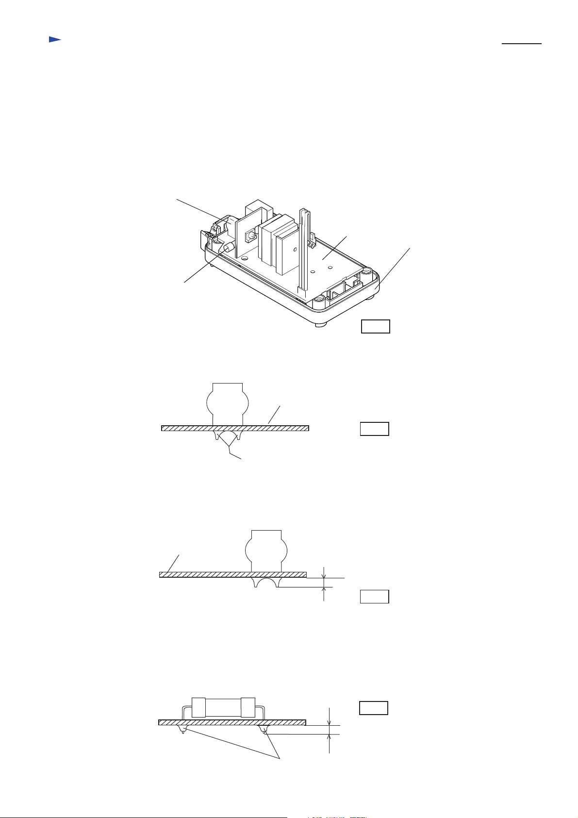
(1) How to find broken varistor
a. In case that the surface of varistor (ref. to the following illustration) has broken or has become black, and
fuse has been cut, the varistor has been damaged.
b. Varistor can be damaged easily, if the charger is plugged in a double voltage of the rating one.
c. It is considered that the varistor has been broken for other reasons, if the fuse is broken while the surface
of varistor is not damaged. In this case circuit board has to be replaced.
Varistor
Circuit board
Charger case set
Fuse
P 2 / 2
Fig.1
(2) Replacing damaged varistor
a. Varistor is assembled on circuit board with solder. Remove it from circuit board
with soldering iron.
Varistor
b. Assemble new varistor to the circuit board by soldering.
c. Cut the surplus of varistor's wire with nipper.
Circuit board
Circuit board
Fig.2
When removing varistor, melt this part with soldering iron
and remove varistor.
Varistor
Less than 3mm
Fig.3
(3) Replacing damaged fuse
a. Fuse is assembled on circuit board with solder. Remove it from circuit board with soldering iron.
b. Assemble new fuse to the circuit board by soldering.
c. Cut the surplus of fuse's wire with nipper.
Fuse
When removing fuse, melt this part with soldering iron
and remove fuse.
Fig.4
Less than 3mm
 Loading...