

Page 1
T
ECHNICAL INFORMATION
PRODUCT
P 1/ 5
Model No.
Description
DC18WA
Charger
CONCEPT AND MAIN APPLICATIONS
Model DC18WA is a Makita charger developed specially for
charging new slide-style Li-ion batteries.
New Makita Li-ion batteries model BL1411G (14.4V-1.1Ah)
and model BL1811G (18V-1.1Ah) can be charged approximately
in 60 minutes. But the maktec band Li-ion batteries designed with
the same concept, model L1451 (14.4V-1.1Ah) and model
L1851(18V-1.1Ah) cannot be charged.
In order to achieve a cost-competitive advantage, this charger
is not equipped with:
• Optimum charging system
• Forced air-cooling system
Also note that it is not compatible with:
• ADP01 Interchangeable adapter
• ADP02 Refreshing adapter
• ADP03 Automatic refreshing adapter
• ADP04 Interchangeable adapter
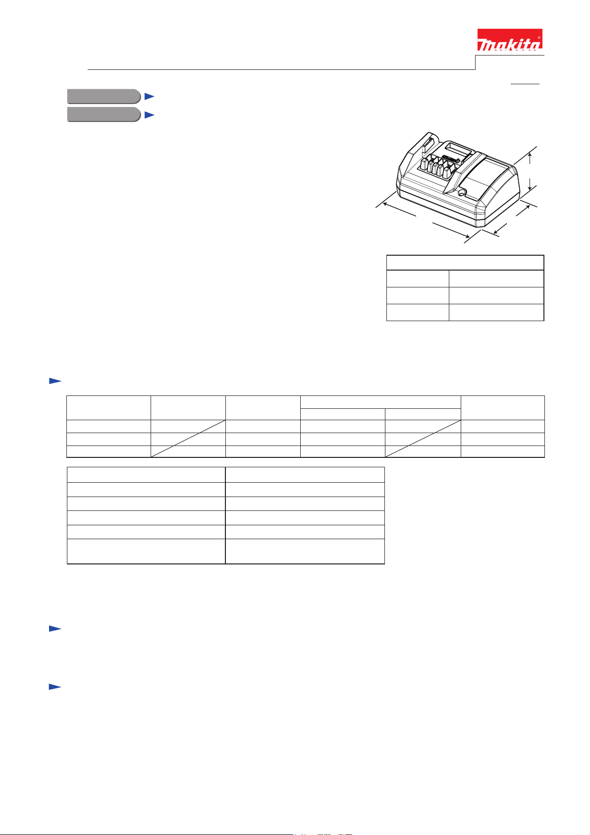
Specification
L
Dimensions: mm (")
Length (L)
Width (W)
Height (H)
H
W
150 (5-7/8)
100 (3-15/16)
65 (2-9/16)
Voltage (V) Cycle (Hz)
110 - 120
100 - 240
220 - 240
Output voltage
Output current
Charging time*
Protection against electric shock Double insulation/ Grounding
Power supply cord: m (ft)
Weight according to
EPTA-Procedure 01/2003:
*The charging time may depend on various conditions such as room temperature,
the condition of battery, etc.
Current (A)
kg (lbs)
50/60 41
50/60
50/60
DC 14.4 - 18V
DC 1.65 - 1.1A
approx. 60 min.
2.0 (6.6)
0.35 (0.77)
Continuous Rating (W)
Input Output
41
41
Standard equipment
No
Optional accessories
No
Standby power (W)
0.3
0.3
0.3
Page 2
P 2/ 5
Repair
CAUTION: Disconnect the charger from the power source for safety before repair/ maintenance!
DC18WA has two different kinds of specifications. Distinguish them by name plate
“DC18WA” and “DC18WA U” and follow each insturction. Do not use the different
parts in repair.
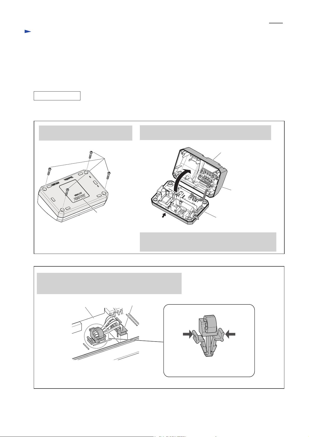
[1] DISASSEMBLY/ASSEMBLY FOR DC18WA
[1] -1. Terminal unit and Charger case complete
DISASSEMBLING
Replace Charger case complete as drawn in Figs. 1 and 2.
Fig. 1
1. Turn Charger upside down and remove
four tapping screws.
Tapping screws
Indication of DC18WA
Fig. 2
3. When replacing Charger case complete;
(1) By pinching Push mount tie, remove it from Charging circuit.
(2) Remove Connector from Charging circuit.
2. Turn Charger over again and open Charger case complete
from rear side.
*Open from
this side
Note: Terminal unit is fully integral with Charger case complete.
When it is necessary to replace Terminal unit, replacing
Charger case complete and Charging condition label is required.
Charger case complete
Terminal unit
Charger case cover
Charging circuit
Connector
Push mount tie
Pinch both levers of Push mount tie
when pulling it off from Charger circuit.
Page 3

Repair
[1] DISASSEMBLY/ASSEMBLY FOR DC18WA
[1] -1. Terminal unit and Charger case complete (cont.)
ASSEMBLING
Assemble Charger case cover and Charger case complete as drawn in Fig. 3.
Fig. 3
P 3
/ 5
1. Set Connector on Charging circuit as drawn below.
Then insert Push mount tie into the hole of
Charging circuit until its levers are fixed in the hole.
Push mount tie
Charging circuit
Connector
3. Assemble Charger case complete to Charger case cover.
2. Push Lead wires firmly between the ribs and
the wall of Charger case cover.
Charger case cover
Lead wires
Be sure to securely tighten four tapping screws.
[1] -2. Replacing Varistor and Fuse
(1) If the cause of Battery charger trouble is the breakage of Varistor and Fuse, you need not replace
Charging circuit, but simply replace Varistor and Fuse.
Sign of Varistor breakage:
Cracks exists in the surface of Varistor.
Cause of Varistor breakage:
Charger is plugged in a power source of two times or more than the rated voltage of Varistor.
Note: If Fuse has burned out meanwhile Varistor is not broken, something else in Charging circuit is probably
causing the trouble. In this case, replace Charger circuit.
(2) Replace Varistor and Fuse. (Fig. 4)
Fig. 4
Varistor/ Fuse is soldered on Charging circuit.
Remove a broken Varistor/ Fuse with soldering iron.
And solder new one with soldering iron.
Fuse
Varistor
Page 4

Repair
[2] DISASSEMBLY/ASSEMBLY FOR DC18WA U
[2] -1. Terminal unit and Charger case complete
DISASSEMBLING
Important: After disconnecting the charger from electric outlet, wait more than 5 minutes before repairing work.
Replace Charger case complete as drawn in Figs. 5 and 6.
Fig. 5
P 4/ 5
1. Turn Charger upside down and remove
four Tapping screws.
Tapping
screws
Indication of
DC18WA U
Fig. 6
3. Hold the connector on Charging circuit and pull up the connector.
2. Turn Charger over again and open Charger case complete from
rear side.
*Open from
this side
Note: Terminal unit is fully integral with Charger case complete.
When it is necessary to replace Terminal unit, replacing
Charger case complete and Charging condition label is required.
Charger case complete
Terminal unit
Charger case cover
Charging circuit Connector
ASSEMBLING
Assemble Charger case complete to Charger case cover by
reversing the disassembly procedure.
Be sure to push Power supply cord firmly between the ribs
and the wall of Charger case cover as drawn in Fig. 7.
Fig. 7
Power supply cord
Page 5

Repair
[2] DISASSEMBLY/ASSEMBLY FOR DC18WA U
[2] -2. Replacing Varistor and Fuse
Neither Varistor nor Fuse is supplied for the repair.
When they have damages, replace Charging circuit with a new one.
P 5
/ 5
 Loading...