

Page 1
ENGLISH (Original instructions)
INSTRUCTION MANUAL
Cordless Metal Shear
BJS160
BJS161
BJS100
BJS101
IMPORTANT: Read Before Using.
010082
1
Page 2
ENGLISH (Original instructions)
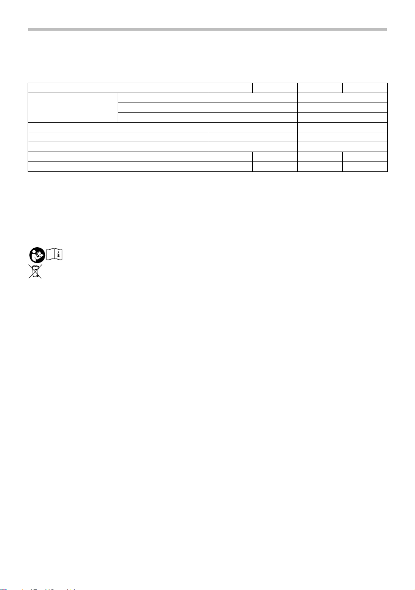
SPECIFICATIONS
Model BJS160 BJS161 BJS100 BJS101
Max. cutting capacities
Min. cutting radius 250 mm 30 mm
Strokes per minute (min-1) 4,300 4,300
Overall length 362 mm 364 mm
• Due to our continuing programme of research and development, the specifications herein are subject to change without notice.
• Specifications and battery cartridge may differ from country to country.
• Weight, with battery cartridge, according to EPTA-Procedure 01/2003
Rated voltage D.C. 14.4V D.C. 18V D.C. 14.4V D.C. 18V
Symbols
The following show the symbols used for the equipment.
Be sure that you understand their meaning before use.
Intended use
The tool is intended for cutting sheet steel and stainless
sheet steel.
For Model BJS160
For European countries only
Noise
The typical A-weighted noise level determined according
to EN60745:
The noise level under working may exceed 80 dB (A).
・ Read instruction manual.
Cd
・ Only for EU countries
Ni-MH
Li-ion
Do not dispose of electric equipment or
battery pack together with household
waste material!
In observance of European Directive
2002/96/EC on waste electric and
electronic equipment, 2006/66/EC on
batteries and accumulators and waste
batteries and accumulators and their
implementation in accordance with
national laws, electric equipment and
battery pack that have reached the end
of their life must be collected separately
and returned to an environmentally
compatible recycling facility.
Sound pressure level (L
Uncertainty (K) : 3 dB(A)
Wear ear protection.
Steel up to 400 N/mm2 1.6 mm (16 ga.) 1.0 mm (20 ga.)
Steel up to 600 N/mm2 1.2 mm (18 ga.) 0.7 mm (23 ga.)
Aluminum up to 200 N/mm2 2.5 mm (13 ga.) 2.5 mm (12 ga.)
Net weight 1.9 kg 2.0 kg 1.9 kg 2.0 kg
END004-4
Vibration
The vibration total value (tri-axial vector sum) determined
according to EN60745:
Work mode : cutting sheet metal
Vibration emission (a
Uncertainty (K) : 1.5 m/s
) : 12.0 m/s
h
2
2
For Model BJS161
For European countries only
Noise
The typical A-weighted noise level determined according
to EN60745:
Sound pressure level (L
Uncertainty (K) : 3 dB(A)
) : 71 dB(A)
pA
The noise level under working may exceed 80 dB (A).
Wear ear protection.
Vibration
ENE037-1
The vibration total value (tri-axial vector sum) determined
according to EN60745:
Work mode : cutting sheet metal
Vibration emission (a
Uncertainty (K) : 1.5 m/s
) : 13.0 m/s
h
2
2
ENG104-1
For Model BJS100
For European countries only
Noise
The typical A-weighted noise level determined according
) : 74 dB(A)
pA
to EN60745:
Sound pressure level (L
Uncertainty (K) : 3 dB(A)
) : 71 dB(A)
pA
The noise level under working may exceed 80 dB (A).
Wear ear protection.
2
ENG218-2
ENG104-1
ENG218-2
ENG104-1
Page 3

Vibration
r
ENG218-2
The vibration total value (tri-axial vector sum) determined
according to EN60745:
Work mode : cutting sheet metal
Vibration emission (a
Uncertainty (K) : 1.5 m/s
) : 12.5 m/s
h
2
2
For Model BJS101
ENG104-1
For European countries only
Noise
The typical A-weighted noise level determined according
to EN60745:
Sound pressure level (L
Uncertainty (K) : 3 dB(A)
) : 71 dB(A)
pA
The noise level under working may exceed 80 dB (A).
Wear ear protection.
ENG218-2
Vibration
The vibration total value (tri-axial vector sum) determined
according to EN60745:
Work mode : cutting sheet metal
Vibration emission (a
Uncertainty (K) : 1.5 m/s
The declared vibration emission value has been
•
) : 13.0 m/s
h
2
2
ENG901-1
measured in accordance with the standard test
method and may be used for comparing one tool
with another.
• The declared vibration emission value may also be
used in a preliminary assessment of exposure.
WARNING:
• The vibration emission during actual use of the
power tool can differ from the declared emission
value depending on the ways in which the tool is
used.
• Be sure to identify safety measures to protect the
operator that are based on an estimation of
exposure in the actual conditions of use (taking
account of all parts of the operating cycle such as
the times when the tool is switched off and when it
is running idle in addition to the trigger time).
ENH101-12
EC Declaration of Conformity
We Makita Corporation as the responsible
manufacturer declare that the following Makita
machine(s):
Designation of Machine:
Cordless Metal Shea
Model No./ Type: BJS100,BJS101,BJS160,BJS161
are of series production and
Conforms to the following European Directives:
98/37/EC until 28th December 2009 and then with
2006/42/EC from 29th December 2009
And are manufactured in accordance with the following
standards or standardised documents:
EN60745
The technical documentation is kept by our authorised
representative in Europe who is:
Makita International Europe Ltd,
Michigan, Drive, Tongwell,
Milton Keynes, MK15 8JD, England
000230
31th July 2009
Tomoyasu Kato
Director
Makita Corporation
3-11-8, Sumiyoshi-cho,
Anjo, Aichi, JAPAN
GEA006-2
General Power Tool Safety
Warnings
WARNING Read all safety warnings and all
instructions. Failure to follow the warnings and
instructions may result in electric shock, fire and/or
serious injury.
Save all warnings and
instructions for future reference.
The term "power tool" in the warnings refers to your
mains-operated (corded) power tool or battery-operated
(cordless) power tool.
Work area safety
1. Keep work area clean and well lit. Cluttered or
dark areas invite accidents.
2. Do not operate power tools in explosive
atmospheres, such as in the presence of
flammable liquids, gases or dust. Power tools
create sparks which may ignite the dust or fumes.
3. Keep children and bystanders away while
operating a power tool. Distractions can cause
you to lose control.
Electrical safety
4. Power tool plugs must match the outlet. Never
modify the plug in any way. Do not use any
adapter plugs with earthed (grounded) power
tools. Unmodified plugs and matching outlets will
reduce risk of electric shock.
5. Avoid body contact with earthed or grounded
surfaces such as pipes, radiators, ranges and
3
Page 4

refrigerators. There is an increased risk of
electric shock if your body is earthed or grounded.
6. Do not expose power tools to rain or wet
conditions. Water entering a power tool will
increase the risk of electric shock.
7. Do not abuse the cord. Never use the cord for
carrying, pulling or unplugging the power tool.
Keep cord away from heat, oil, sharp edges or
moving parts. Damaged or entangled cords
increase the risk of electric shock.
8. When operating a power tool outdoors, use an
extension cord suitable for outdoor use. Use of
a cord suitable for outdoor use reduces the risk of
electric shock.
9. If operating a power tool in a damp location is
unavoidable, use a ground fault circuit
interrupter (GFCI) protected supply. Use of an
GFCI reduces the risk of electric shock.
Personal safety
10. Stay alert, watch what you are doing and use
common sense when operating a power tool.
Do not use a power tool while you are tired or
under the influence of drugs, alcohol or
medication. A moment of inattention while
operating power tools may result in serious
personal injury.
11. Use personal protective equipment. Always
wear eye protection. Protective equipment such
as dust mask, non-skid safety shoes, hard hat, or
hearing protection used for appropriate conditions
will reduce personal injuries.
12. Prevent unintentional starting. Ensure the
switch is in the off-position before connecting
to power source and/or battery pack, picking
up or carrying the tool. Carrying power tools with
your finger on the switch or energising power tools
that have the switch on invites accidents.
13. Remove any adjusting key or wrench before
turning the power tool on. A wrench or a key left
attached to a rotating part of the power tool may
result in personal injury.
14. Do not overreach. Keep proper footing and
balance at all times. This enables better control
of the power tool in unexpected situations.
15. Dress properly. Do not wear loose clothing or
jewellery. Keep your hair, clothing, and gloves
away from moving parts. Loose clothes,
jewellery or long hair can be caught in moving
parts.
16. If devices are provided for the connection of
dust extraction and collection facilities,
ensure these are connected and properly used.
Use of dust collection can reduce dust-related
hazards.
Power tool use and care
17. Do not force the power tool. Use the correct
power tool for your application. The correct
power tool will do the job better and safer at the
rate for which it was designed.
18. Do not use the power tool if the switch does
not turn it on and off. Any power tool that cannot
be controlled with the switch is dangerous and
must be repaired.
19. Disconnect the plug from the power source
and/or the battery pack from the power tool
before making any adjustments, changing
accessories, or storing power tools. Such
preventive safety measures reduce the risk of
starting the power tool accidentally.
20. Store idle power tools out of the reach of
children and do not allow persons unfamiliar
with the power tool or these instructions to
operate the power tool. Power tools are
dangerous in the hands of untrained users.
21. Maintain power tools. Check for misalignment
or binding of moving parts, breakage of parts
and any other condition that may affect the
power tool’s operation. If damaged, have the
power tool repaired before use. Many accidents
are caused by poorly maintained power tools.
22. Keep cutting tools sharp and clean. Properly
maintained cutting tools with sharp cutting edges
are less likely to bind and are easier to control.
23. Use the power tool, accessories and tool bits
etc. in accordance with these instructions,
taking into account the working conditions
and the work to be performed. Use of the power
tool for operations different from those intended
could result in a hazardous situation.
Battery tool use and care
24. Recharge only with the charger specified by
the manufacturer. A charger that is suitable for
one type of battery pack may create a risk of fire
when used with another battery pack.
25. Use power tools only with specifically
designated battery packs. Use of any other
battery packs may create a risk of injury and fire.
26. When battery pack is not in use, keep it away
from other metal objects, like paper clips,
coins, keys, nails, screws or other small metal
objects, that can make a connection from one
terminal to another. Shorting the battery
terminals together may cause burns or a fire.
27. Under abusive conditions, liquid may be
ejected from the battery; avoid contact. If
contact accidentally occurs, flush with water. If
liquid contacts eyes, additionally seek medical
help. Liquid ejected from the battery may cause
irritation or burns.
4
Page 5

Service
28. Have your power tool serviced by a qualified
repair person using only identical replacement
parts. This will ensure that the safety of the power
tool is maintained.
29. Follow instruction for lubricating and
changing accessories.
30. Keep handles dry, clean and free from oil and
grease.
GEB067-1
CORDLESS SHEAR SAFETY
WARNINGS
1. Hold the tool firmly.
2. Secure the workpiece firmly.
3. Keep hands away from moving parts.
4. Edges and chips of the workpiece are sharp.
Wear gloves. It is also recommended that you
put on thickly bottomed shoes to prevent
injury.
5. Do not put the tool on the chips of the
workpiece. Otherwise it can cause damage
and trouble on the tool.
6. Do not leave the tool running. Operate the tool
only when hand-held.
7. Always be sure you have a firm footing.
Be sure no one is below when using the tool in
high locations.
8. Do not touch the blade or the workpiece
immediately after operation; they may be
extremely hot and could burn your skin.
9. Avoid cutting electrical wires. It can cause
serious accident by electric shock.
SAVE THESE INSTRUCTIONS.
WARNING:
DO NOT let comfort or familiarity with product
(gained from repeated use) replace strict adherence
to safety rules for the subject product. MISUSE or
failure to follow the safety rules stated in this
instruction manual may cause serious personal
injury.
ENC007-4
IMPORTANT SAFETY
INSTRUCTIONS
FOR BATTERY CARTRIDGE
1. Before using battery cartridge, read all
instructions and cautionary markings on (1)
battery charger, (2) battery, and (3) product
using battery.
2. Do not disassemble battery cartridge.
3. If operating time has become excessively
shorter, stop operating immediately. It may
result in a risk of overheating, possible burns
and even an explosion.
4. If electrolyte gets into your eyes, rinse them
out with clear water and seek medical
attention right away. It may result in loss of
your eyesight.
5. Do not short the battery cartridge:
(1) Do not touch the terminals with any
conductive material.
(2) Avoid storing battery cartridge in a
container with other metal objects such as
nails, coins, etc.
(3) Do not expose battery cartridge to water
or rain.
A battery short can cause a large current
flow, overheating, possible burns and
even a breakdown.
6. Do not store the tool and battery cartridge in
locations where the temperature may reach or
exceed 50 ゚ C (122 ゚ F).
7. Do not incinerate the battery cartridge even if
it is severely damaged or is completely worn
out. The battery cartridge can explode in a fire.
8. Be careful not to drop or strike battery.
9. Do not use dropped or struck battery.
SAVE THESE INSTRUCTIONS.
Tips for maintaining maximum battery life
1. Charge the battery cartridge before completely
discharged.
Always stop tool operation and charge the
battery cartridge when you notice less tool
power.
2. Never recharge a fully charged battery
cartridge.
Overcharging shortens the battery service life.
3. Charge the battery cartridge with room
temperature at 10 ゚ C - 40 ゚ C (50 ゚ F - 104 ゚ F).
Let a hot battery cartridge cool down before
charging it.
5
Page 6

FUNCTIONAL DESCRIPTION
CAUTION:
• Always be sure that the tool is switched off and the
battery cartridge is removed before adjusting or
checking function on the tool.
Installing or removing battery cartridge
1
2
1. Button
2. Red part
3. Battery cartridge
firm grasp on tool.
To start the tool, slide the switch lever toward the "I (ON)"
position. For continuous operation, press the front of the
switch lever to lock it.
To stop the tool, press the rear of the switch lever, then
slide it toward the "O (OFF)" position.
Indication lamp with multi function
1. Indicating lamp
1
3
010083
Always switch off the tool before insertion or
•
removal of the battery cartridge.
• To remove the battery cartridge, withdraw it from
the tool while sliding the button on the front of the
cartridge.
• To insert the battery cartridge, align the tongue on
the battery cartridge with the groove in the housing
and slip it into place. Always insert it all the way
until it locks in place with a little click. If you can see
the red part on the upper side of the button, it is not
locked completely. Insert it fully until the red part
cannot be seen. If not, it may accidentally fall out of
the tool, causing injury to you or someone around
you.
• Do not use force when inserting the battery
cartridge. If the cartridge does not slide in easily, it
is not being inserted correctly.
Switch action
1
010088
CAUTION:
• Before inserting the battery cartridge into the tool,
always check to see that the switch lever actuates
properly and returns to the "OFF" position when the
rear of the switch lever is depressed.
• Switch can be locked in "ON" position for ease of
operator comfort during extend use. Apply caution
when locking tool in "OFF" position and maintain
1. Switch lever
010089
Indication lamps are located in two positions.
− Battery cartridge replacing signal
− When the battery power is almost used up
during operation, the red lamp lights up and
the tool stops immediately. Replace the
battery with fully charged one when the red
lamp lights up.
− Accidental re-start preventive function
− Even if the battery cartridge is inserted on the
tool with the slide switch in the "I (ON)"
position, the tool does not start. At this time,
the lamp flickers slowly and this shows that
the accidental re-start preventive function is at
work.
− To start the tool, first slide the slide switch
toward the "O (OFF)" position and then slide it
toward the "I (ON)" position.
ASSEMBLY
CAUTION:
• Always be sure that the tool is switched off and the
battery cartridge is removed before carrying out
any work on the tool.
Adjusting the blade clearance
For BJS160 and BJS161 only
Adjust the clearance between the side blade and the
center blade according to the thickness of the workpiece.
6
Page 7

1
010085
First use a hex wrench to loosen the screw.
1
3
5
010086
Then use the hex wrench to adjust the clearance by
tightening or loosening the bolt. There may be a slight
difference between clearance of both sides of the center
blade.
Check the smaller clearance with the thickness gauge
and adjust it.
When using the thickness gauge to adjust the blade
clearance, refer to the table.
Workpiece thickness (mm) Marking on thickness gauge
006428
After adjusting the clearance, tighten the screw securely.
4
Less than 0.8 0.5
0.8 - 1.3 1.0
More than 1.3
1. Hex wrench
2. Screw
2
1. Center blade
2
2. Thickness gauge
3. Side blade
4. Hex wrench
5. Hex socket head
bolt
1.5
Storing hex wrench
1. Hex wrench
OPERATION
Lubrication
1. Oil supply
1
2
3
010084
Before operation, lubricate the contact point of the center
blade and the pin. To keep good cutting performance,
also use a cutting lubricant from time to time during
operation.
2. Center blade
3. Pin
OPERATION
010090
Turn the tool on and set front ends of the side blades on
the workpiece. Now simply move the tool forward,
keeping the side blades flush with the workpiece surface.
1
010087
Store the hex wrench as shown in the figure when not in
use.
010091
CAUTION:
• When cutting a small portion of the workpiece, you
may have difficulty completing the end of the cut. In
that case, try to cut it again, pulling the workpiece
back slightly.
MAINTENANCE
CAUTION:
• Always be sure that the tool is switched off and the
battery cartridge is removed before attempting to
perform inspection or maintenance.
7
Page 8

NOTICE:
• Never use gasoline, benzine, thinner, alcohol or the
like. Discoloration, deformation or cracks may
result.
The tool and its air vents have to be kept clean. Regularly
clean the tool's air vents or whenever the vents start to
become obstructed.
Replacing carbon brushes
1. Limit mark
1
001145
Remove and check the carbon brushes regularly.
Replace when they wear down to the limit mark. Keep
the carbon brushes clean and free to slip in the holders.
Both carbon brushes should be replaced at the same
time. Use only identical carbon brushes.
Insert the top end of slotted bit screwdriver into the notch
in the tool and remove the holder cap cover by lifting it up.
2
1
3
010092
Use a screwdriver to remove the brush holder caps. Take
out the worn carbon brushes, insert the new ones and
secure the brush holder caps.
1. Brush holder
cover
2. Notch
3. Screwdriver
1. Brush holder
cap
2. Screwdriver
Service Centers to replace the blades.
For BJS160 and BJS161
Material
Mild steel plate
(SPCC)
Stainless steel plate
(SUS304)
Aluminum plate
(A-5052)
010094
Cutting thickness
(mm)
1.2
Life of blades
(m)
2001.6
150
4002.5
For BJS100 and BJS101
Material
Mild steel plate
(SPCC)
Stainless steel plate
(SUS304)
010739
Cutting thickness
(mm)
0.7
Life of blades
(m)
1201.0
50
To maintain product SAFETY and RELIABILITY, repairs,
any other maintenance or adjustment should be
performed by Makita Authorized Service Centers, always
using Makita replacement parts.
ACCESSORIES
CAUTION:
• These accessories or attachments are
recommended for use with your Makita tool
specified in this manual. The use of any other
accessories or attachments might present a risk of
injury to persons. Only use accessory or
attachment for its stated purpose.
If you need any assistance for more details regarding
these accessories, ask your local Makita Service Center.
• Thickness gauge
• Center blade
• Side blade R
• Side blade L
• Hex wrench
• Various type of Makita genuine batteries and
chargers
1
2
010093
Reinstall the holder cap cover on the tool.
Replacing blades
The service life of the blades varies in terms of the
workpiece to be cut. The following reference tables
indicate the approximate service life of the blades.
When the blades become dull, ask Makita Authorized
8
Page 9

9 10 11 12
Page 10

Page 11

Page 12

884904C228
Makita Corporation Anjo, Aichi, Japan
 Loading...