

Makita BJR240 User Manual [en, es, fr]
INSTRUCTION MANUAL
MANUEL D'INSTRUCTION
MANUAL DE INSTRUCCIONES
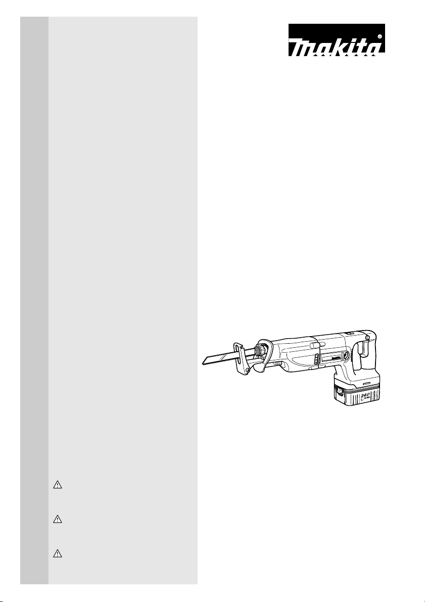
Cordless Recipro Saw
Scie récipro sans fil
Sierra de sable inalámbrico
BJR240
001660
WARNING:
For your personal safety, READ and UNDERSTAND before using.
SAVE THESE INSTRUCTIONS FOR FUTURE REFERENCE.
AVERTISSEMENT:
Pour votre propre sécurité, prière de lire attentivement avant l’utilisation.
GARDER CES INSTRUCTIONS POUR RÉFÉRENCE ULTÉRIEURE.
ADVERTENCIA:
Para su seguridad personal, LEA DETENIDAMENTE este manual antes de usar la herramienta.
GUARDE ESTAS INSTRUCCIONES PARA FUTURA REFERENCIA.
ENGLISH
SPECIFICATIONS
MODEL BJR240
Length of stroke 32 mm (1-1/4”)
Strokes per minute High speed: 0 - 2,700/min. Low speed: 0 - 2,300/min.
Overall length 469 mm (18-1/2”)
Net weight 4.4 kg (9.7 lbs)
Battery Charger DC24SA DC24WA
Input A.C. only 50 Hz - 60 Hz
Output D.C. 7.2 V - 24 V
Battery Cartridge BH2420 BH2433 BH2420 BH2433
Voltage 24 V
Charging time 30 min. 60 min. 55 min. 90 min.
• Due to our continuing programme of research and development, the specifications herein are subject to change
without notice.
• Note: Specifications may differ from country to country.
GENERAL SAFETY RULES
USA003-2
(FOR ALL BATTERY OPERATED TOOLS)
WARNING:
Read and understand all instructions.
Failure to follow all instructions listed below,
may result in electric shock, fire and/or serious personal injury.
SAVE THESE INSTRUCTIONS
Work Area
1. Keep your work area clean and well lit. Cluttered
benches and dark areas invite accidents.
2. Do not operate power tools in explosive atmo-
spheres, such as in the presence of flammable
liquids, gases, or dust. Power tools create sparks
which may ignite the dust or fumes.
3. Keep bystanders, children, and visitors away
while operating a power tool. Distractions can
cause you to lose control.
Electrical Safety
4. A battery operated tool with integral batteries or
a separate battery pack must be recharged only
with the specified charger for the battery. A
charger that may be suitable for one type of battery
may create a risk of fire when used with another battery.
5. Use battery operated tool only with specifically
designated battery pack. Use of any other batter-
ies may create a risk of fire.
Personal Safety
6. Stay alert, watch what you are doing, and use
common sense when operating a power tool. Do
not use tool while tired or under the influence of
drugs, alcohol, or medication. A moment of inat-
tention while operating power tools may result in
serious personal injury.
7. Dress properly. Do not wear loose clothing or
jewelry. Contain long hair. Keep your hair, clothing, and gloves away from moving parts. Loose
clothes, jewelry, or long hair can be caught in moving parts.
8. Avoid accidental starting. Be sure switch is in
the locked or off position before inserting battery pack. Carrying tools with your finger on the
switch or inserting the battery pack into a tool with
the switch on invites accidents.
9. Remove adjusting keys or wrenches before turning the tool on. A wrench or a key that is left
attached to a rotating part of the tool may result in
personal injury.
10. Do not overreach. Keep proper footing and balance at all times. Proper footing and balance
enable better control of the tool in unexpected situations.
11. Use safety equipment. Always wear eye protection. Dust mask, non-skid safety shoes, hard hat, or
hearing protection must be used for appropriate conditions.
2

Tool Use and Care
12. Use clamps or other practical way to secure and
support the workpiece to a stable platform. Hold-
ing the work by hand or against your body is unstable and may lead to loss of control.
13. Do not force tool. Use the correct tool for your
application. The correct tool will do the job better
and safer at the rate for which it is designed.
14. Do not use tool if switch does not turn it on or
off. A tool that cannot be controlled with the switch is
dangerous and must be repaired.
15. Disconnect battery pack from tool or place the
switch in the locked or off position before making any adjustments, changing accessories, or
storing the tool. Such preventive safety measures
reduce the risk of starting the tool accidentally.
16. Store idle tools out of reach of children and
other untrained persons. Tools are dangerous in
the hands of untrained users.
17. When battery pack is not in use, keep it away
from other metal objects like: paper clips, coins,
keys, nails, screws, or other small metal objects
that can make a connection from one terminal to
another. Shorting the battery terminals together
may cause sparks, burns, or a fire.
18. Maintain tools with care. Keep cutting tools
sharp and clean. Properly maintained tools with
sharp cutting edge are less likely to bind and are
easier to control.
19. Check for misalignment or binding of moving
parts, breakage of parts, and any other condition
that may affect the tool’s operation. If damaged,
have the tool serviced before using. Many acci-
dents are caused by poorly maintained tools.
20. Use only accessories that are recommended by
the manufacturer for your model. Accessories
that may be suitable for one tool may create a risk of
injury when used on another tool.
SERVICE
21. Tool service must be performed only by qualified
repair personnel. Service or maintenance per-
formed by unqualified personnel may result in a risk
of injury.
22. When servicing a tool, use only identical
replacement parts. Follow instructions in the
Maintenance section of this manual. Use of unau-
thorized parts or failure to follow Maintenance
instructions may create a risk of shock or injury.
SPECIFIC SAFETY RULES
USB029-2
DO NOT let comfort or familiarity with
product (gained from repeated use)
replace strict adherence to cordless
recipro saw safety rules. If you use this
tool unsafely or incorrectly, you can suffer serious personal injury.
1. Hold tool by insulated gripping surfaces when
performing an operation where the cutting tool
may contact hidden wiring. Contact with a “live”
wire will make exposed metal parts of the tool “live”
and shock the operator.
2. Be aware that this tool is always in an operating
condition, because it does not have to be
plugged into an electrical outlet.
3. Always use safety glasses or goggles. Ordinary
eye or sun glasses are NOT safety glasses.
4. Avoid cutting nails. Inspect workpiece for any
nails and remove them before operation.
5. Do not cut oversize workpiece.
6. Check for the proper clearance beyond the workpiece before cutting so that the blade will not
strike the floor, workbench, etc.
7. Hold the tool firmly.
8. Make sure the blade is not contacting the workpiece before the switch is turned on.
9. Keep hands away from moving parts.
10. Always switch off and wait for the blade to come
to a complete stop before removing the blade
from the workpiece.
11. Do not touch the blade or the workpiece immediately after operation; they may be extremely hot
and could burn your skin.
12. Some material contains chemicals which may be
toxic. Take caution to prevent dust inhalation
and skin contact. Follow material supplier safety
data.
SAVE THESE INSTRUCTIONS
WARNING:
MISUSE or failure to follow the safety
rules stated in this instruction manual
may cause serious personal injury.
3

SYMBOLS
The followings show the symbols used for tool.
V............................volts
.......................direct current
.......................no load speed
.../min....................revolutions or reciprocation per
minute
USD301-1
IMPORTANT SAFETY INSTRUCTIONS FOR CHARGER & BATTERY CARTRIDGE
1. SAVE THESE INSTRUCTIONS- This manual contains important safety and operating instructions for battery charger.
2. Before using battery charger, read all instructions and cautionary markings on (1) battery
charger, (2) battery, and (3) product using battery.
3. CAUTION - To reduce risk of injury, charge only
MAKITA rechargeable batteries marked on the
USC002-3
charger label. Other types of batteries may burst
causing personal injury and damage.
4. Do not expose charger to rain or snow.
5. Use of an attachment not recommended or sold
by the battery charger manufacturer may result
in a risk of fire, electric shock, or injury to persons.
6. To reduce risk of damage to electric plug and
cord, pull by plug rather than cord when disconnecting charger.
7. Make sure cord is located so that it will not be
stepped on, tripped over, or otherwise subjected
to damage or stress.
8. An extension cord should not be used unless
absolutely necessary. Use of improper extension
cord could result in a risk of fire and electric
shock. If extension cord must be used, make
sure:
a. That pins on plug of extension cord are the
same number, size, and shape as those of
plug on charger;
b. That extension cord is properly wired and in
good electrical condition; and
c. That wire size is at least as large as the one
specified in the table below.
Table 1: RECOMMENDED MINIMUM AWG SIZE FOR EXTENSION CORDS FOR BATTERY CHARGERS
Length of Cord (Feet) 25 50 100 150
AWG Size of Cord 18 18 18 16
9. Do not operate charger with damaged cord or
plug - replace them immediately.
10. Do not operate charger if it has received a sharp
blow, been dropped, or otherwise damaged in
any way; take it to a qualified serviceman.
11. Do not disassemble charger or battery cartridge;
take it to a qualified serviceman when service or
repair is required. Incorrect reassembly may
result in a risk of electric shock or fire.
12. To reduce risk of electric shock, unplug charger
from outlet before attempting any maintenance
or cleaning. Turning off controls will not reduce
this risk.
13. The battery charger is not intended for use by
young children or infirm persons without supervision.
14. Young children should be supervised to ensure
that they do not play with the battery charger.
15. If operating time has become excessively
shorter, stop operating immediately. It may
result in a risk of overheating, possible burns
and even an explosion.
16. If electrolyte gets into your eyes, rinse them out
with clear water and seek medical attention right
away. It may result in loss of your eyesight.
ADDITIONAL SAFETY RULES
FOR CHARGER & BATTERY CARTRIDGE
1. Do not charge Battery Cartridge when temperature is BELOW 10°C (50°F) or ABOVE 40°C
(104°F).
2. Do not attempt to use a step-up transformer, an
engine generator or DC power receptacle.
3. Do not allow anything to cover or clog the
charger vents.
4. Do not short the battery cartridge:
(1) Do not touch the terminals with any conduc-
tive material.
(2) Avoid storing battery cartridge in a con-
tainer with other metal objects such as nails,
coins, etc.
4
(3) Do not expose battery cartridge to water or
rain.
A battery short can cause a large current flow,
overheating, possible burns and even a breakdown.
5. Do not store the tool and Battery Cartridge in
locations where the temperature may reach or
exceed 50°C (122°F).
6. Do not incinerate the Battery Cartridge even if it
is severely damaged or is completely worn out.
The battery cartridge can explode in a fire.
7. Be careful not to drop, shake or strike battery.
8. Do not charge inside a box or container of any
kind. The battery must be placed in a well ventilated area during charging.
SAVE THESE INSTRUCTIONS
SYMBOLS
The following show the symbols used for the charger. Be
sure that you understand their meaning before use.
............Ready to charge
...............Charging
...............Charging complete
...........Delay charge (Cooling)
...........Defective battery
...........Conditioning
............Cooling abnormality
FUNCTIONAL DESCRIPTION
CAUTION:
• Always be sure that the tool is switched off and the
battery cartridge is removed before adjusting or
checking function on the tool.
Installing or removing battery cartridge
1
2
• Always switch off the tool before insertion or
removal of the battery cartridge.
001661
3
1. Red part
2. Button
3. Battery cartridge
• To remove the battery cartridge, withdraw it from
the tool while sliding the button on the side of the
cartridge.
• To insert the battery cartridge, align the tongue on
the battery cartridge with the groove in the housing
and slip it into place. Always insert it all the way
until it locks in place with a little click. If you can see
the red part on the upper side of the button, it is not
locked completely. Insert it fully until the red part
cannot be seen. If not, it may accidentally fall out of
the tool, causing injury to you or someone around
you.
• Do not use force when inserting the battery car-
tridge. If the cartridge does not slide in easily, it is
not being inserted correctly.
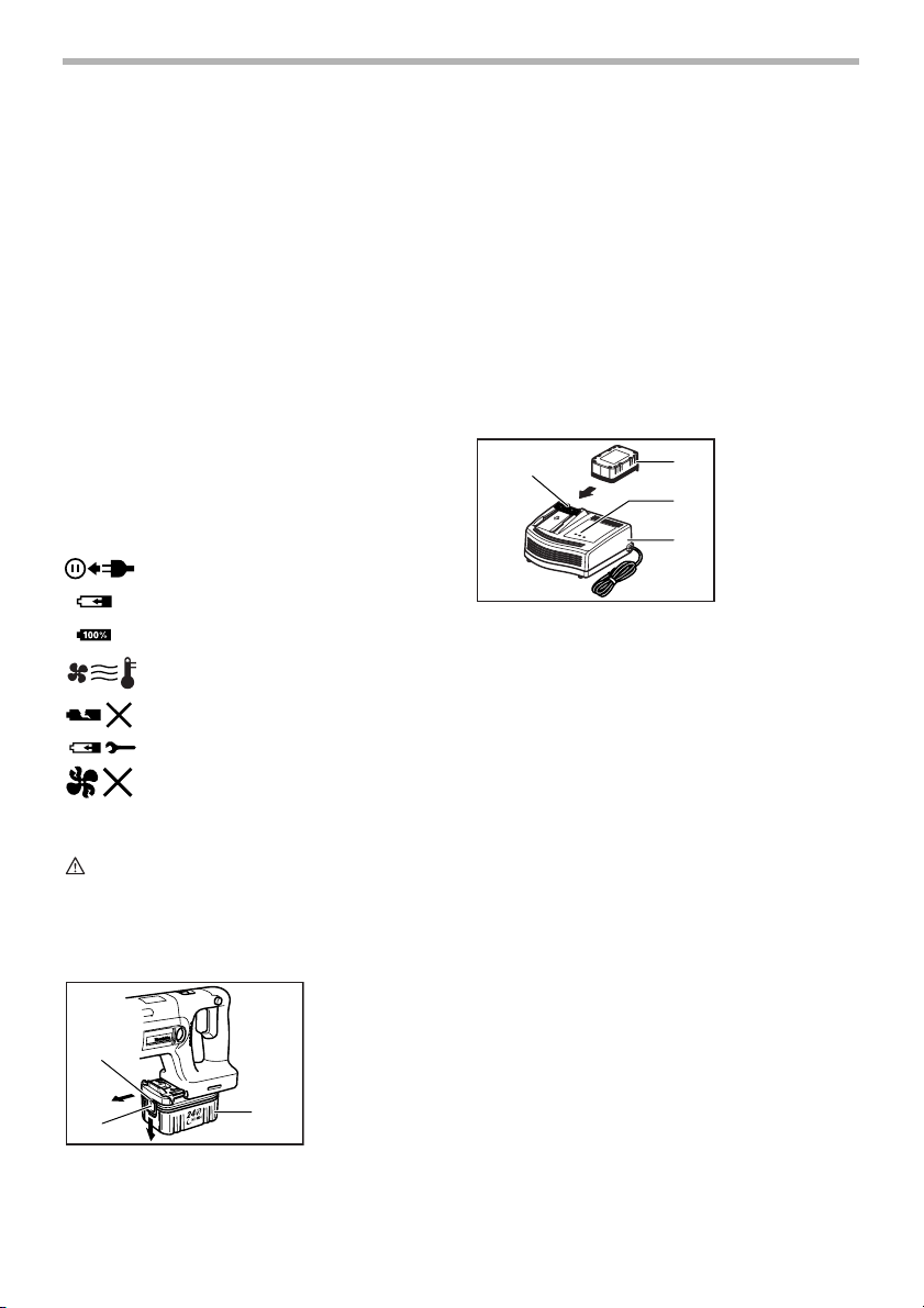
Charging
2
1. Plug the battery charger into the proper AC voltage
source. Two charging lights will flash in green color
repeatedly.
2. Insert the battery cartridge into charger until it stops
adjusting to the guide of charger. Terminal cover of
charger can be opened with inserting and closed
with pulling out the battery cartridge.
3. When the battery cartridge is inserted, the charging
light color will change from green to red and charging will begin. The charging light will keep lighting
up lit steadily during charging. One red charging
light indicates charged condition in 0 - 80% and two
red ones indicates 80 - 100%.
4. With finish of charge, the charging lights will
change from two red ones to two green ones.
5. If you leave the battery cartridge in the charger
after the charging cycle is complete, the charger
will switch into its “trickle charge (maintenance
charge)” mode which will last approximately 24
hours.
6. After charging, unplug the charger from the power
source.
NOTE:
• The battery charger is for charging Makita battery
cartridge. Never use it for other purposes or for
other manufacturer’s batteries.
• When you charge a new battery cartridge or a bat-
tery cartridge which has not been used for a long
period of time, it may not accept a full charge. This
is a normal condition and does not indicate a prob-
001662
1. Battery car-
1
2. Terminal cover
3
3. Charging lights
4. Battery charger
4
tridge
5
lem. You can recharge the battery cartridge fully
after discharging it completely and recharging a
couple of times.
• If you charge a battery cartridge from a just oper-
ated tool or battery cartridge which has been left in
a location exposed to direct sunlight for a long time,
the charging light may flash in red color. If this
occurs, wait for a while. Charging will begin after
the battery cartridge is cooled by the cooling fan
installed in the charger. (DC24SA only) When the
temperature on battery is more than approx. 70°C,
two charging lights may flash in red color, and when
approx. 50°C - 70°C, one charging light in red color.
• If the charging light flashes alternately in green and
red color, charging is not possible. The terminals on
the charger or battery cartridge are clogged with
dust or the battery cartridge is worn out or damaged.
Cooling system (DC24SA only)
• This charger is equipped with cooling fan for heated
battery in order to enable the battery to prove its
own performance. Sound of cooling air comes out
during cooling, which means no trouble on the
charger.
• Yellow light will flash for warning in the following
cases.
- Trouble on cooling fan
- Incomplete cool down of battery, such as, being
clogged with dust
The battery can be charged in spite of the yellow
warning light. But the charging time will be longer
than usual in this case.
• Check the sound of cooling fan, vent on the charger
and battery, which can be sometime clogged with
dust.
• The cooling system is in order although no sound of
cooling fan comes out, if the yellow warning light
will not flash.
• Always keep clean the vent on charger and battery
for cooling.
• The products should be sent to repair or mainte-
nance, if the yellow warning light will frequently
flash.
Conditioning charge (DC24SA only)
Conditioning charge can extend the life of battery by
automatically searching the optimum charging condition
for the batteries in every situations.
The battery employed in the following conditions repeatedly, will be worn out shortly, and yellow warning light
may flash.
1. Recharge of battery with its high temperature
2. Recharge of battery with its low temperature
3. Recharge of full charged battery
4. Over-discharge of battery (continue to discharge
battery in spite of down of power.)
The charging time of such battery is longer than usual.
Trickle charge (Maintenance charge)
If you leave the battery cartridge in the charger to prevent
spontaneous discharging after full charge, the charger
will switch into its “trickle charge (maintenance charge)”
mode and keep the battery cartridge fresh and fully
charged.
Tips for maintaining maximum battery life
1. Charge the battery cartridge before completely dis-
charged.
• Always stop tool operation and charge the bat-
tery cartridge when you notice less tool power.
2. Never recharge a fully charged battery cartridge.
• Overcharging shortens the battery service life.
3. Charge the battery cartridge with room temperature
at 10°C - 40°C (50°F - 104°F).
• Let a hot battery cartridge cool down before
charging it.
4. Charge the Nickel Metal Hydride battery cartridge
when you do not use it for more than six months.
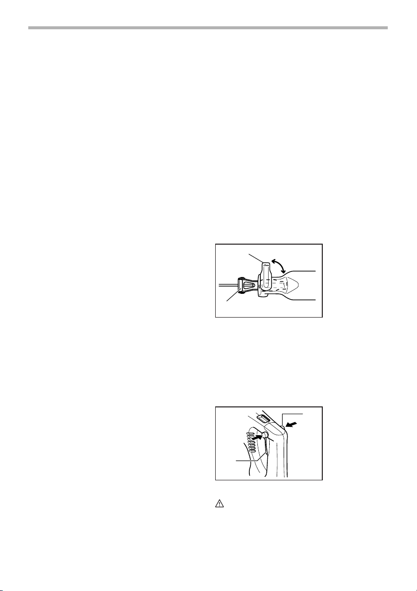
Adjusting the shoe
1
001663
1. Lever
2. Shoe
2
When the blade loses its cutting efficiency in one place
along its cutting edge, reposition the shoe to utilize a
sharp, unused portion of its cutting edge. This will help to
lengthen the life of the blade. To reposition the shoe,
loosen the lever counterclockwise and slide the shoe forward or back to the desired position. Then tighten the
lever clockwise to firmly secure the shoe.
Switch action
001664
1
1. Lock-off button
2. Switch trigger
2
CAUTION:
• Before inserting the battery cartridge into the tool,
always check to see that the switch trigger actuates
properly and returns to the “OFF” position when
released.
6
To prevent the switch trigger from being accidentally
pulled, a lock-off button is provided.
To start the tool, press in the lock-off button and pull the
switch trigger. The lock-off button can be pressed in from
either left or right side of the tool. Tool speed is increased
by increasing pressure on the switch trigger. Release the
switch trigger to stop.
Electric brake
This tool is equipped with an electric brake. If the tool
consistently fails to quickly stop after switch trigger
release, have tool serviced at a Makita service center.
Speed change
BA
001665
1
1. Speed change
lever
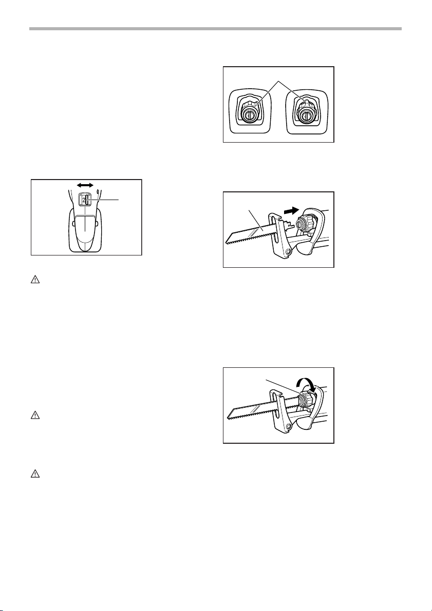
001666
1
23
1. Blade clamp
sleeve
2. Released position
3. Fixed position
Insert the saw blade into the blade clamp as far as it will
go. The blade clamp sleeve rotates and the saw blade is
fixed. Make sure that the saw blade cannot be extracted
even though you try to pull it out.
001667
1. Blade
1
CAUTION:
• Always set the speed change lever fully to the cor-
rect position. If you operate the tool with the speed
change lever positioned half-way, the tool may be
damaged.
• Do not use the speed change lever while the tool is
running. The tool may be damaged.
To change the speed, first switch off the tool and then
slide the speed change lever to the A side (2) for high
speed or B side (1) for low speed. Be sure that the speed
change lever is set to the correct position before operation. Use the right speed for your job.
ASSEMBLY
CAUTION:
• Always be sure that the tool is switched off and the
battery cartridge is removed before carrying out
any work on the tool.
Installing or removing the saw blade
CAUTION:
• Always clean out all chips or foreign matter adher-
ing to the blade, blade clamp and/or slider. Failure
to do so may cause insufficient tightening of the
blade, resulting in a serious injury.
To install the saw blade, always make sure that the blade
clamp sleeve is in released position before inserting the
saw blade. If the blade clamp sleeve is in fixed position,
rotate the sleeve to the released position.
NOTE:
• If you do not insert the saw blade deep enough, the
saw blade may be ejected unexpectedly during
operation. This can be extremely dangerous.
To remove the saw blade, rotate the blade clamp sleeve
in the direction of the arrow fully. The saw blade is
removed and the blade clamp sleeve is fixed at the
released position.
1
001668
1. Blade clamp
sleeve
NOTE:
• If you remove the saw blade without rotating the
blade clamp sleeve fully, the sleeve may not be
fixed. In this case, rotate the blade clamp sleeve
fully, then make the sleeve fixed at the released
position.
7

OPERATION
CAUTION:
• Always press the shoe firmly against the workpiece
during operation. If the shoe is held away from the
workpiece during operation, strong vibration and/or
twisting will be produced, causing the blade to snap
dangerously.
• Always wear gloves to protect your hands from hot
flying chips when cutting metal.
• Be sure to always wear suitable eye protection
which conforms with current national standards.
• Always use a suitable coolant (cutting oil) when cut-
ting metal. Failure to do so will cause premature
blade wear.
• If the tool is operated continuously until the battery
cartridge has discharged, allow the tool to rest for
15 minutes before proceeding with a fresh battery.
Press the shoe firmly against the workpiece. Do not allow
the tool to bounce. Bring the blade into light contact with
the workpiece. First, make a pilot groove using a slower
speed. Then use a faster speed to continue cutting.
001669
MAINTENANCE
CAUTION:
• Always be sure that the tool is switched off and the
battery cartridge is removed before attempting to
perform inspection or maintenance.
Replacing carbon brushes
Remove and check the carbon brushes regularly.
Replace when they wear down to the limit mark. Keep
the carbon brushes clean and free to slip in the holders.
Both carbon brushes should be replaced at the same
time. Use only identical carbon brushes.
001145
1. Limit mark
1
Use a screwdriver to remove the brush holder caps. Take
out the worn carbon brushes, insert the new ones and
secure the brush holder caps.
1
After replacing brushes, insert the battery cartridge into
the tool and break in brushes by running tool with no load
for about 1 minute. Then check the tool while running and
electric brake operation when releasing the switch trigger. If electric brake is not working well, ask your local
Makita service center for repair.
To maintain product SAFETY and RELIABILITY, repairs,
any other maintenance or adjustment should be performed by Makita Authorized or Factory Service Centers,
always using Makita replacement parts.
001670
2
1. Brush holder
cap
2. Screwdriver
ACCESSORIES
CAUTION:
• These accessories or attachments are recom-
mended for use with your Makita tool specified in
this manual. The use of any other accessories or
attachments might present a risk of injury to persons. Only use accessory or attachment for its
stated purpose.
If you need any assistance for more details regarding
these accessories, ask your local Makita Service Center.
• Recipro saw blades
• Various type of Makita genuine batteries and charg-
ers
• Plastic carrying case
MAKITA LIMITED ONE YEAR WARRANTY
Warranty Policy
Every Makita tool is thoroughly inspected and tested
before leaving the factory. It is warranted to be free of
defects from workmanship and materials for the period of
ONE YEAR from the date of original purchase. Should
any trouble develop during this one year period, return
the COMPLETE tool, freight prepaid, to one of Makita’s
Factory or Authorized Service Centers. If inspection
shows the trouble is caused by defective workmanship or
material, Makita will repair (or at our option, replace)
without charge.
This Warranty does not apply where:
• repairs have been made or attempted by others:
• repairs are required because of normal wear and
tear:
8
EN0006-1

• the tool has been abused, misused or improperly
maintained:
• alterations have been made to the tool.
IN NO EVENT SHALL MAKITA BE LIABLE FOR ANY
INDIRECT, INCIDENTAL OR CONSEQUENTIAL DAMAGES FROM THE SALE OR USE OF THE PRODUCT.
THIS DISCLAIMER APPLIES BOTH DURING AND
AFTER THE TERM OF THIS WARRANTY.
MAKITA DISCLAIMS LIABILITY FOR ANY IMPLIED
WARRANTIES, INCLUDING IMPLIED WARRANTIES
OF “MERCHANTABILITY” AND “FITNESS FOR A SPECIFIC PURPOSE,” AFTER THE ONE YEAR TERM OF
THIS WARRANTY.
This Warranty gives you specific legal rights, and you
may also have other rights which vary from state to state.
Some states do not allow the exclusion or limitation of
incidental or consequential damages, so the above limitation or exclusion may not apply to you. Some states do
not allow limitation on how long an implied warranty lasts,
so the above limitation may not apply to you.
9
 Loading...