

Makita BJR181, BJR181Z, BJR181SF, BJR181SFE Technical Information
T
ECHNICAL INFORMATION
Models No.
BJR181
PRODUCT
P 1 /14
Description
Cordless Recipro Saw
CONCEPT AND MAIN APPLICATIONS
Model BJR181 has been developed as the first cordless recipro saw that is
powered by 18V/3.0Ah Li-ion battery.
Whilst having the same basic construction as our AC model JR3050T,
features the additional and original advantages, for example, as follows;
Ergonomic grip best-fitting to overhead application
Two-light type LED job light for more illuminated work-surface
Belt clip
This new product will be available in the following variations.
Model No.
BJR181Z
BJR181SF
BJR181SFE 2
BJR181
All models also include the accessories listed below in "Standard equipment".
Charger
No
Battery
type quantity
No No
BL1830 DC18SC
No
BL1830 DC18SC
No
1
No
2
Plastic
carrying case
No
All countries other than
Yes
No
Yes
Offered to
All countries
USA, Canada,
Mexico, Panama
USA, Canada,
Mexico, Panama
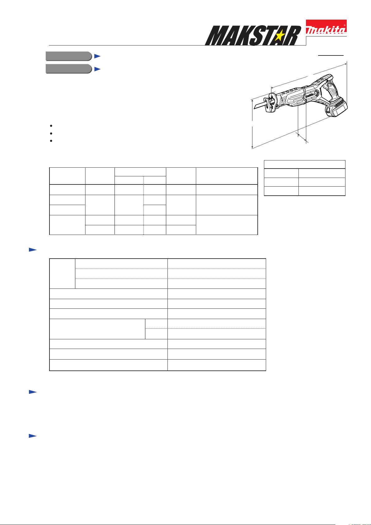
H
Dimensions: mm (")
Length (L)
Width (W)
Height (H)
L
W
499 (19-5/8)
91 (3-5/8)
234 (9-1/4)
Specification
Voltage: V
Battery
Max output (W) 290
Length of stroke: mm (")
No load speed: min-1=spm 0 - 2,900
Max cutting capacities: mm (")
[when cutting with a 300mm blade]
Variable speed Yes
Electric brake
Net weight*: kg (lbs)
*Includes battery BL1830
Capacity: Ah
Cell
wood 255 (10)
pipe
18
3.0
Li-ion
28 (1-1/8)
dia. 130 (5-1/8)
Yes
3.7 (8.1)
Standard equipment
Recipro saw blade for wood .................................. 1 pc
Recipro saw blade for metal .................................. 1 pc
Note: The standard equipment for the tool shown above may differ from country to country.
Optional accessories
Charger DC18SC
Charger DC24SA
Charger DC24SC
Li-ion battery BL1830
Assorted recipro saw blades
P 2 / 14
Repair
CAUTION: Remove the recipro saw blade and battery cartridge from the machine
for safety before repair/ maintenance !
[1] NECESSARY REPAIRING TOOLS
Code No. Description Use for
1R146 L type torx wrench M6 Removing Shoe guide
1R232 Pipe 30
1R242 Removing / installing Needle bearing 1012
1R250 Press-fitting Oil seal 14
1R267 Removing Shift button
1R269 Removing Ball bearing 6001DDW
1R291 Removing /installing Retaining rings S-18 and S-12
1R296 Removing Pin 3 from the Blade clamp section
1R314
---
Round bar foe arbor 13-100
Round bar foe arbor 26-100
Spring pin extractor 2.5
Bearing extractor
Retaining ring S and R pliers
Spring pin extractor 1.5
Torx bit VT-25
Recipro saw blade
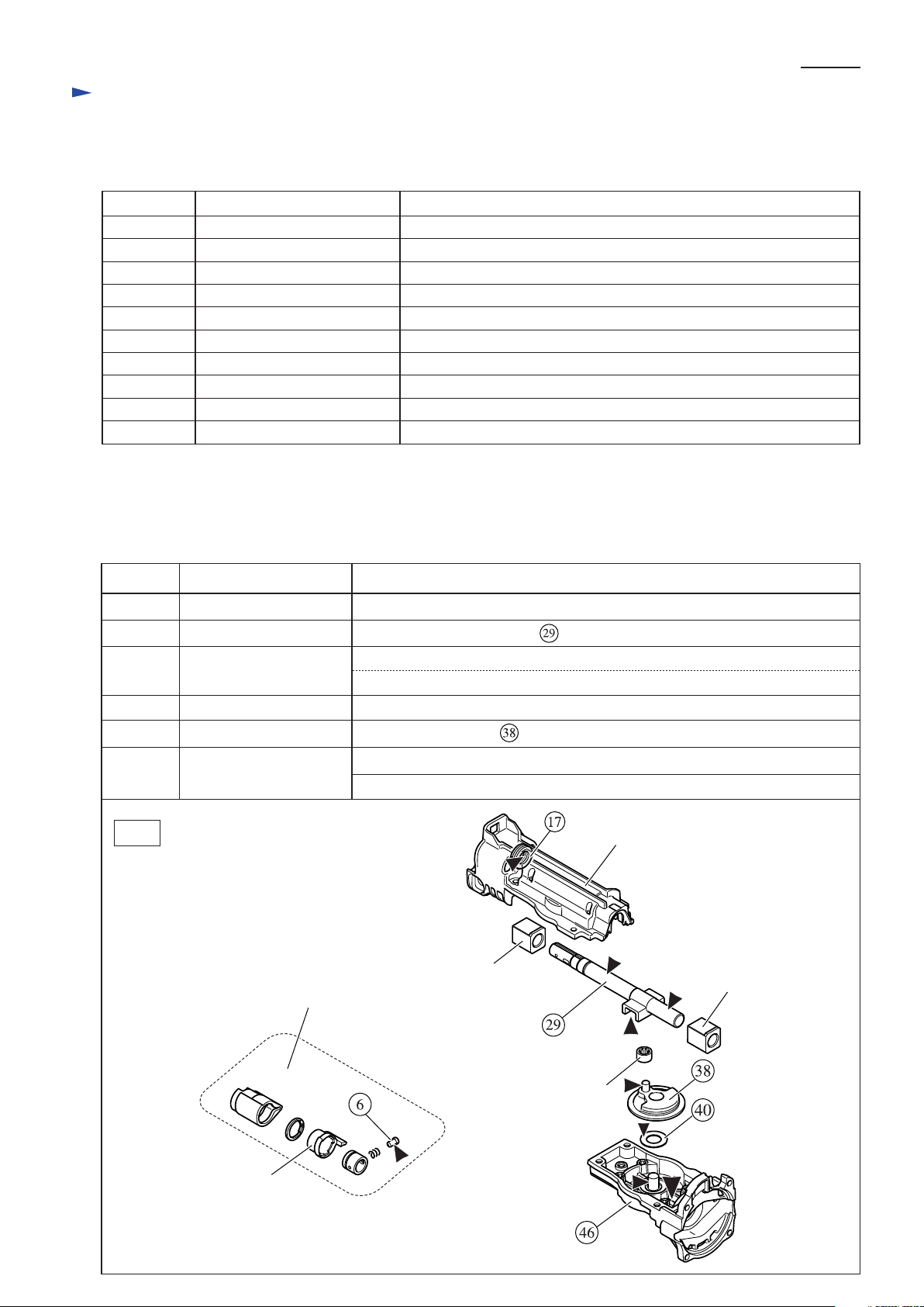
[2] LUBRICATION and ADHESIVE
Lubrication: Apply Makita grease FA No.2 to the following portions designated with the black triangle to protect
parts and product from unusual abrasion. (Fig. 1)
Adhesive: When reusing threadlocker coated screws, be sure to apply adhesive before tightening.
Recommended adhesives are ThreeBond 1321B or 1342B, or Loctite 242.
Removing/ installing Needle bearing 1012
Removing /installing Torx socket head screw
Assembling Pin 3 to the Blade clamp section
Item No. Description Portion to be lubricate
6 Shoulder pin 5
17 X ring 14 Inside surface that contacts Slider complete
29
38
40
46
Fig. 1
Slider complete
Gear assembly Surface of crank pin that contacts Needle nearing 708
Flat washer 14 Surface that contacts Gear assembly
Gear housing complete
Blade clamp section
Pin head that contacts Driving sleeve
Surface that contacts Plane bearing 14A
Surface that contacts Needle bearing 708 (Put approx. 7g.)
Pin 10 (the gear shaft for Gear assembly)
Gear room (Put approx. 10g.)
Gear housing cover complete
Plane bearing 14A
Plane bearing 14A
Driving sleeve
Needle bearing 708
Repair
[3] DISASSEMBLY/ASSEMBLY
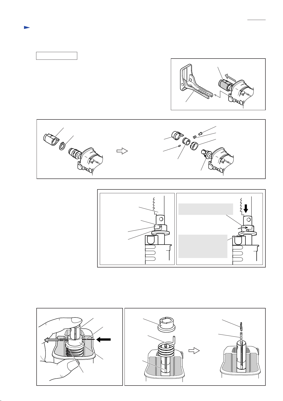
[3] -1. Blade Clamp Section
DISASSEMBLING
1) Remove Shoe. If the Blade clamp section is positioned inside
Gear housing, pull it out of Gear housing. (Fig. 2)
2) After removing Protector, remove Retaining ring S-18 with
Retaining Ring S and R pliers (No.1R291).
Then remove the following parts:
Driving sleeve, Shoulder pin 5, Compression spring 6,
Pin 3 (of 6mm length), Guide sleeve, Driving sleeve guide
Now Sleeve appears. (Fig. 3)
Fig. 3
P 3 / 14
Fig. 2
Blade clamp section
Shoe
Protector
Retaining ring S-18
3) Sleeve is still locked at this
stage. Therefore, release it
using a recipro saw blade
as illustrated in Fig. 4.
Driving sleeve
Pin 3
(of 6mm length)
Fig. 4
[Sleeve Locked] [Sleeve Released]
Recipro saw blade
Pin 3, 19.8mm long
Sleeve
groove
Guide sleeve
Sleeve
Push the recipro saw blade.
Now sleeve can rotate.
Pin 3 is positioned at
the lower end of the
groove on Sleeve
when Sleeve is released.
Shoulder pin 5
Compression spring 6
Driving sleeve guide
4) While putting your finger on the top of Slider to close the slit of Slider, remove Pin 3 (of 19.8mm length) by pushing
with a thin bar. (Fig. 5)
Note: Be sure to put your finger on the top of Slider or Push plate will pop out from the slit of Slider.
5) Remove Sleeve and Torsion spring 17 from Slider, then take Push plate and Compression spring 2 out of the slit of
Slider. (Fig. 6)
Fig. 5 Fig. 6
Slider
thin bar
Sleeve
Pin 3, 19.8mm long
Sleeve
Torsion
spring 17
Slider
Push plate
Compression
spring 2
Repair
[3] -1. Blade Clamp Section (cont.)
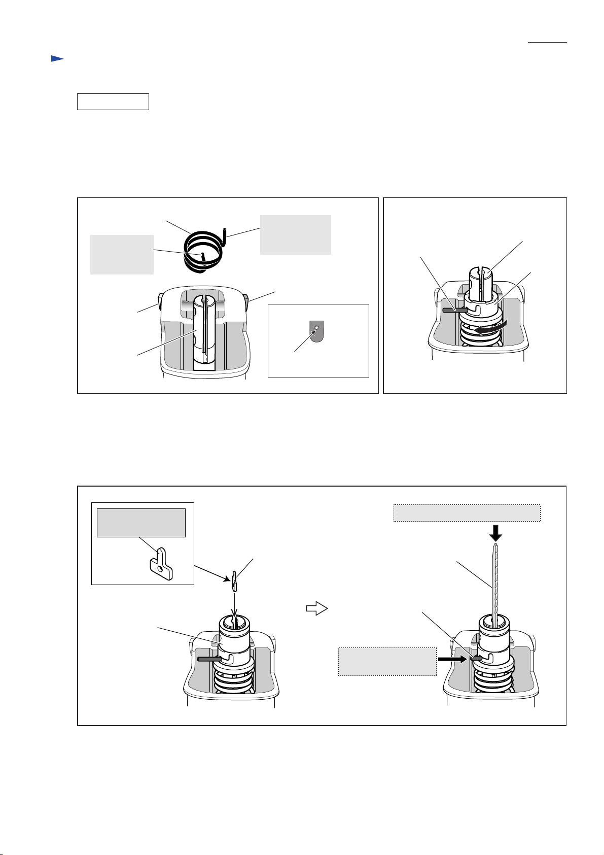
ASSEMBLING
1) Assemble Torsion spring 17 to Slider as illustrated in Fig. 7.
Important: Be sure that Torsion spring 17 is not reversible when assemble to Slider.
Follow the instruction described in Fig. 7.
2) Insert Compression spring 2 into the slit of Slider.
3) Install Sleeve on Slider, and lock Pin 3 provisionally by turning Sleeve clockwise. (Fig. 8)
P 4 / 14
Fig. 7
Torsion spring 17
Insert this end
into the slit of
Slider.
Shift button
Slider
4) Mount Guide sleeve provisionally, then put Push plate into the slit of Slider as illustrated to left in Fig. 9.
Important: Be sure that Push plate is not reversible when installed.
While pushing Push plate straight into Slider with recipro saw blade, insert Pin 3 (of 19.8mm length) through the hole
of Push plate as illustrated to right in Fig. 11. Then remove Guide sleeve.
Note: Guide sleeve is used as a jig, not assembled to Slider yet in this step.
Fig. 9
This end has to
be positioned
on the Cap side.
Cap
[Side view of cap]
Cap has an insert hole
for Shift button.
Fig. 8
Slider
Pin 3, 19.8mm long
Sleeve
This projection must
face the blade side.
Guide sleeve
Push plate
While pushing recipro saw blade,
Recipro saw blade
Pin 3, 19.8mm long
insert pin 3 through
the hole of push plate.
P 5 /14
Repair
[3] -1. Blade Clamp Section (cont.)
5) While fitting the two projections of Driving sleeve in the concavities of Sleeve, push Driving sleeve into Gear housing.
At this time, turn Driving sleeve clockwise so that the protruding portion of Driving sleeve cannot be interfered by
Gear housing. After Driving sleeve is pushed into Gear housing to the full, turn Driving sleeve clockwise to lock Pin 3
in place. (Fig. 10)
Note: Driving sleeve is used as a jig to lock Pin 3 in place, not assembled to Slider in this step.
6) Remove Driving sleeve.
Fig. 10
Driving sleeve
Sleeve
Projections
7) Assemble the following parts to Slider (Refer to Fig. 3.):
Driving sleeve guide, Guide sleeve, Pin 3 (of 6mm length), Shoulder pin 5, Compression spring 6
8) Put Driving sleeve over Guide sleeve and secure with Retaining ring S-18 using No.1R291.
Then cover Driving sleeve with Protector. (When installing Driving sleeve, fit its projections in the concavities of
Sleeve and Driving sleeve guide.)
Concavities
Sleeve
Driving sleeve
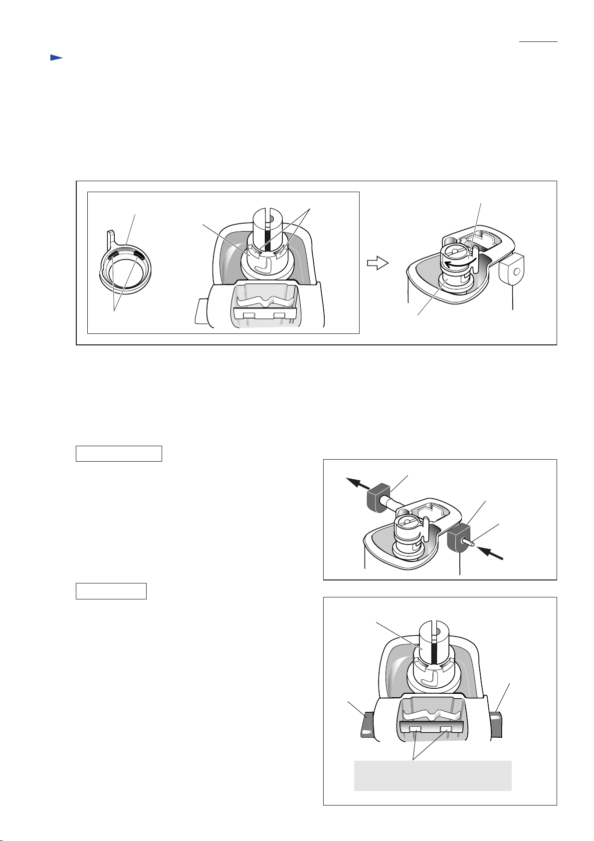
[3] -2. Shift Button and Cap
DISASSEMBLING
Shift button can be removed from Gear housing cover by
inserting a thin bar into the hole of Cap and push the bar.
(Fig. 11)
Fig. 11
Shift button
Cap
ASSEMBLING
1) Replace Cap by new one because removal of Shift button
damages the inside surface of Cap.
2) From Shift button, remove all the plastic dust scraped off
the removed Cap. Insert Shift button through the holes in
the both sides of Gear housing cover.
Then press-fit Shift button in the new Cap by hand.
Important:
Be sure to assemble Shift button to Gear housing cover
so that the two notches of Shift button face the side
opposite to slider as illustrated in Fig. 12.
thin bar
Fig. 12
Slider
Shift button
Cap
These notches of Shift button must
face the side opposite to Slider.
 Loading...