

Page 1
T
Description
ECHNICAL INFORMATION
Models No.
BJR141
Cordless Recipro Saw
PRODUCT
P 1 /10
W
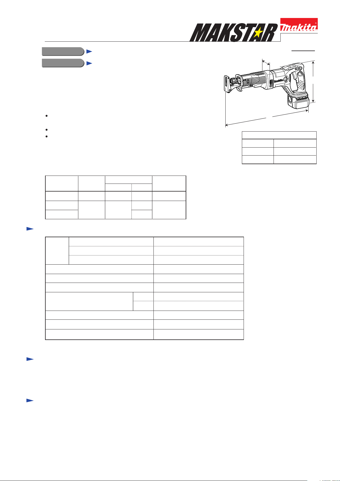
CONCEPT AND MAIN APPLICATIONS
Model BJR141 has been developed as the successor model to
the current Model JR140D 14.4V cordless recipro saw.
While having the same basic construction as Model JR140D,
features the following additional advantages;
Lightweight design achieved by using Li-ion battery
as a power unit instead of Ni-cd battery.
More work amount on a single full battery charge
Non-skid handle angled and contoured ergonomically for
best-fitting to reciprocating cutting
This product is available in the following variations.
Model No.
BJR141Z
BJR141RF
BJR181RFE 2
Charger
Battery
type quantity
No No
BL1430 DC18RA
No
1
Specification
Voltage: V
Battery
Max output (W) 280
Length of stroke: mm (")
No load speed: min-1=spm 0 - 2,700
Max cutting capacities: mm (")
[when cutting with a 160mm blade]
Capacity: Ah
Cell
wood 90 (3-1/2)
pipe
Plastic
carrying case
No
Yes
14.4
3.0
Li-ion
23 (7/8)
90 (3-1/2)
L
Dimensions: mm (")
Length (L)
Width (W)
Height (H)
H
466 (18-3/8)
79 (3-1/8)
226 (8-7/8)
Variable speed Yes
Electric brake
Net weight*: kg (lbs)
*Includes battery BL1430
Yes
3.1 (6.8)
Standard equipment
Recipro saw blade for metal ............................................................... 1
Recipro saw blade for composite material (wood plus metal) ........... 1
Plastic carrying case ........................................................................... 1
Note: The standard equipment for the tool shown above may differ from country to country.
Optional accessories
Charger DC18RA
Charger DC24RC
Charger DC24SC
Li-ion battery BL1430
Assorted recipro saw blades
Page 2
P 2 /10
Repair
CAUTION: Remove recipro saw blade and battery cartridge from the machine
for safety before repair/ maintenance !
[1] NECESSARY REPAIRING TOOLS
Code No. Description Use for
1R030 Bearing setting pipe 2.5-17.2 Press-fitting Dust seal 14 in Gear housing cover complete
1R269 Removing Ball bearing 6001DDW from the drive-end of Armature
1R291 Removing/installing Retaining ring S-18 from/on Blade clamp section
--- Recipro saw blade Assembling Pin 3 to Blade clamp section
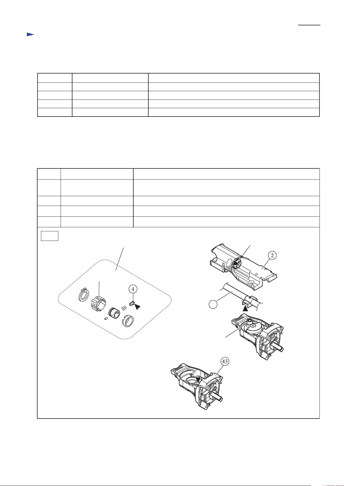
[2] LUBRICATION and ADHESIVE
Lubrication: Apply Makita grease FA No.2 to the following portions designated with the black triangle to protect
parts and product from unusual abrasion. (Fig. 1)
Adhesive: When reusing threadlocker coated screws, be sure to apply adhesive before tightening.
Recommended adhesives are Threebond 1342 or Loctite 242.
Item No. Description Portion to be lubricate
2 Gear housing cover complete
4 Shoulder pin 5
Bearing extractor
Retaining ring S and R pliers
Inside surface of the lip portion of Dust seal 14
(Any kind of lubricating grease can be used.)
Pin head that contacts Driving sleeve
17
Slider complete Surface that contacts Needle bearing 708 (Put approx. 9g.)
43 Gear housing Gear room (Put approx. 9g.)
Fig. 1
Blade clamp section
Driving sleeve
Needle bearing 708
Dust seal 14
17
Page 3
Repair
[3] DISASSEMBLY/ASSEMBLY
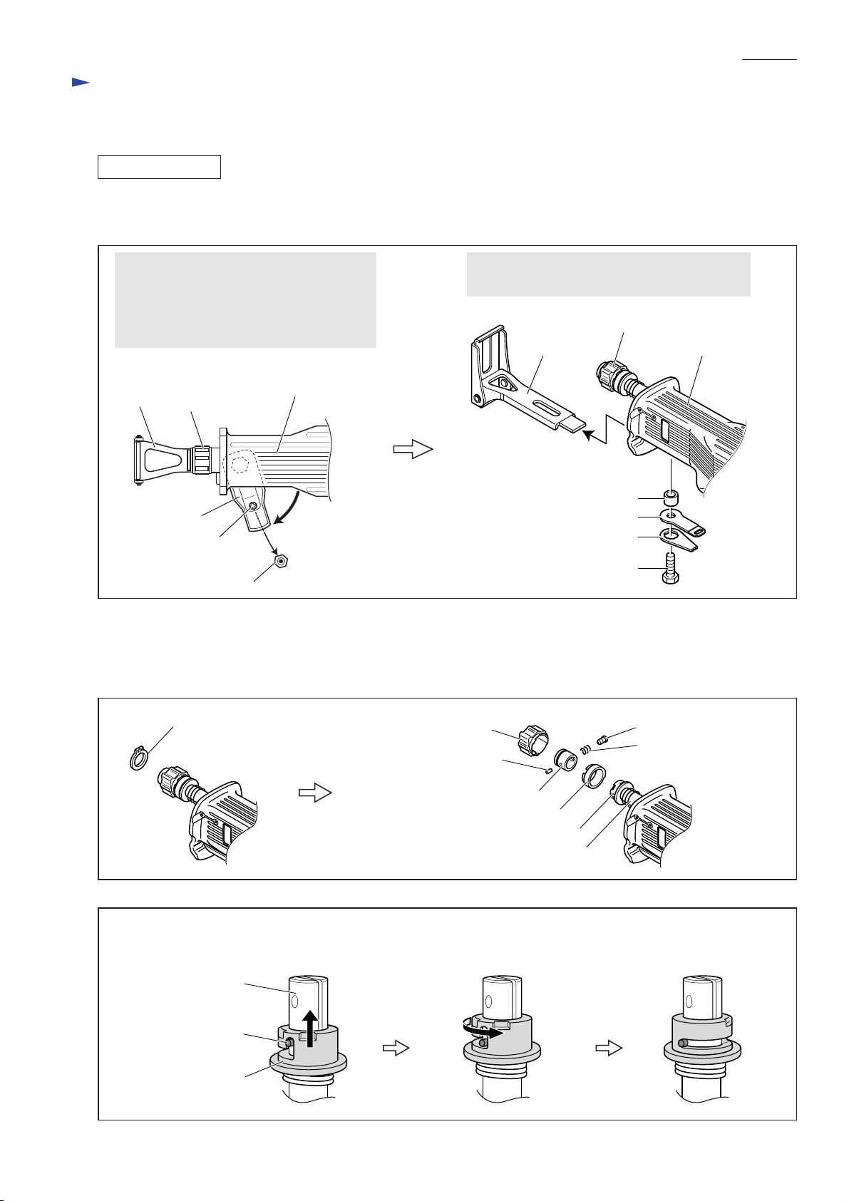
[3] -1. Blade Clamp Section
DISASSEMBLING
1) Remove Shoe as illustrated in Fig. 2.
Note: If the Blade clamp section is positioned inside Gear housing, pull it out of Gear housing.
Fig. 2
P 3 /10
Turn Lever 60 in the direction of the arrow.
Remove Pan head screw M4x10.
Remove Lever 60.
Note: Hex nut M4 will be left in Lever 60.
Be careful not to lose it.
[View from top]
Shoe
Blade clamp section
Lever 60
Pam head screw
M4x10
Hex nut M4
2) Remove Retaining ring S-18 using 1R291. The following parts can now be removed (Fig. 3):
Driving sleeve, Shoulder pin 5, Compression spring 6, Pin 3 (of 6mm length), Guide sleeve, Driving sleeve guide
Note: Sleeve is still locked on Slider in this step.
3) Unlock Sleeve from Slider as illustrated in Fig. 4.
Fig. 3
Insulation cover
By unscrewing Hex bolt M8x25, Shoe can now
be removed as illustrated below.
Blade clamp section
Shoe
Sleeve 9
Inner plate
Lock plate
Hex bolt M8x25
Insulation cover
Retaining ring S-18
Fig. 4
Pull up Sleeve until it stops against
Pin 3 (of 19.8mm length).
Slider
Pin 3
(of 19.8mm length)
Sleeve
Driving sleeve
Pin 3 (of 6mm length)
Guide sleeve
Driving sleeve guide
Turn Sleeve in the direction
of the arrow.
Shoulder pin 5
Compression spring 6
Sleeve
Slider
Sleeve is now unlocked.
Page 4

P 4 /10
Repair
[3] -1. Blade Clamp Section (cont.)
4) While putting your finger on the top of Slider to close the slit of Slider, remove Pin 3 (of 19.8mm length) by pushing
with a thin bar. (Fig. 5)
Note: Be sure to put your finger on the top of Slider or Push plate will pop out from the slit of Slider.
5) Remove Sleeve and Torsion spring 17 from Slider. Take out Push plate and Compression spring 2 from the slit of
Slider. (Fig. 6)
Fig. 5 Fig. 6
Pin 3
Slider
Sleeve
thin bar
ASSEMBLING
1) Assemble Torsion spring 17 to Slider then Sleeve to Slider as illustrated in Fig. 7.
Important: Torsion spring 17 is not reversible when assembled to Slider.
2) Put Compression spring 2 into the slit of Slider by provisionally locking Sleeve with Pin 3 (of 19.8mm length). (Fig. 8)
Fig. 7
Torsion spring 17
Shoulder pin 5
insertion hole
(of 19.8mm length)
Be sure that this end is
positioned on the opposite
side to Shoulder pin 5
insertion hole.
Put this end in
the slit of Slider.
Sleeve
Torsion
spring 17
Sleeve
hole
Push plate
Compression
spring 2
Slider
Fig. 8
Turn Sleeve in the direction
of the arrow so that Pin 3
insertion hole can be seen.
Sleeve
Gear housing
cover complete
Insert Pin 3 (of 19.8mm length) into
the hole provisionally.
Note: Be sure that the top of Pin 3
is not seen in the slit of Slider.
Pin 3 (of 19.8mm length)
Put this end of
Torsion spring 17
into the hole of
Sleeve.
Put Compression spring 2 into
the slit of Slider.
Compression
spring 2
Page 5

P 5 /10
Repair
[3] -1. Blade Clamp Section (cont.)
3) Install Guide sleeve on Sleeve provisionally. Put Push plate into the slit of Slider as illustrated in Fig. 9.
Note: 1. Push plate is not reversible when installed.
2. Guide sleeve is used as a jig in this step. Do not assemble to Slider yet.
4) Insert Push plate straight into Slider using recipro saw blade until the hole of Push plate is aligned with the hole of Slider.
Insert Pin 3 (of 19.8mm length) through the holes of Push plate and Slider. (Fig. 10)
Fig. 9
Fig. 10
This protrusion must
face the blade side.
Push plate
Guide sleeve
Pin 3
(of 19.8mm length)
5) Remove Guide sleeve, and install Driving sleeve on Sleeve provisionally. Then lock Sleeve as illustrated in Fig. 11.
Note: Driving sleeve is used as a jig to lock Sleeve in this step. Do not assemble to Slider yet.
Fig. 11
Hold Driving sleeve and turn it together with Sleeve
in the direction of the arrow until Sleeve stops against
Pin 3 (of 19.8mm length).
Driving sleeve
recipro saw blade
Pin 3 (of 19.8mm length)
hole of Slider
Sleeve
Compression spring 2
Push Sleeve towards
Gear housing side.
Sleeve is now locked.
Sleeve
Pin 3
(of 19.8mm length)
[Gear housing side]
6) Remove Driving sleeve.
7) Assemble the following parts to Slider (Refer to Fig. 3.):
Driving sleeve guide, Guide sleeve, Shoulder pin 5,
Compression spring 6, Pin 3 (of 6mm length)
8) Install Driving sleeve on Guide sleeve and secure with
Retaining ring S-18 using 1R291.
Note: When installing Driving sleeve, fit its protrusions
in the notches of Sleeve and Driving sleeve guide.
(Fig. 12)
Fig. 12
protrusion
Driving sleeve
Driving sleeve guide
notch
notch
Sleeve
Page 6

Repair
[3] -2. Slider Section
DISASSEMBLING
1) Remove Shoe. (See Fig. 2 in page 3.)
2) Remove Blade clamp section. (See [3] -1. Blade Clamp Section in pages 3 and 4.)
3) Remove Insulation cover;
If replacing with new one, cut away using cutter knife.
If reusing removed Insulation cover, remove as illustrated in Fig. 13.
Fig. 13
P 6 /10
Insulation cover has two raised
portions on its inside surface to
prevent from falling off from
the machine.
Insulation cover,
viewed from rear
raised portion (B)
raised portion (A)
4) Separate Gear housing cover complete from Gear housing
by unscrewing four M5x18 Pan head screws. (Fig. 14)
5) Remove two Plates that fix Plane bearing 14 by unscrewing
four M5x16 Pan head screws.
Remove Plane bearing 14 on the Motor housing side. (Fig. 15)
6) Move Slider towards the Motor housing side.
Slider can now be removed together with Plane bearing 14 on
the blade side by pulling in the direction of the gray arrow.
(Fig. 16)
Turn Insulation cover inside out
by hand until the raised portion (A)
is reached.
Insulation cover
Pull Insulation cover in the direction
of the arrow bit by bit while levering
off from Gear housing section using
two slotted screwdrivers.
Gear housing section
Fig. 14
Pan head screw M5x18 (4pcs)
Slider section
Gear housing
cover complete
Fig. 15 Fig. 16
Pan head screw M5x16 (4pcs)
Plate (2pcs)
[blade side]
Plane bearing 14
Slider
Gear housing
cover complete
[Motor housing side]
Gear housing
Plane bearing 14,
on the blade side Slider
Page 7

P 7 /10
Repair
[3] -2. Slider Section (cont.)
ASSEMBLING
Do the reverse of the disassembling steps.
Note 1: If replacing Dust seal 14 of Gear housing cover complete, press-fit using 1R030 as illustrated in Fig. 18.
Note 2: Plane bearing 14 is not reversible when assembled to Slider. Be sure to assemble each Plane bearing 14 to Slider
so that the stepped end of each Plane bearing is placed as illustrated in Fig. 19.
Note 3: Apply threadlocker to four M5x16 Pan head screws when fastening Slider section to Gear housing cover complete.
(Recommended adhesives: Threebond 1342, Loctite 242) (Fig. 20)
Note 4: Do not to forget to apply Makita grease FA No.2 to the crank portion of Slider. (Fig. 20)
Note 5: When assembling Gear housing cover complete to Gear housing, tighten four M5x18 Pan head screws while
pushing Gear housing cover complete against Motor housing (Fig. 21).
Note 6: Apply water or soap water to the inside surface of Insulation cover for easy installation over Gear housing section.
Fig. 18 Fig. 19
Fit the tapered end of 1R030 to Dust seal 14.
1R030
tapered end
Dust seal 14
Fig. 20 Fig. 21
: portion to apply threadlocker
: portion to apply Makita grease FA No.2
Gear housing
cover complete
Slider
Gear housing
cover complete
Pan head screw
M5x16 (4pcs)
[blade side]
stepped end
Gear housing
Plane bearing 14
Slider
Plane bearing 14
[Motor housing side]
Pan head screw M5x18 (4pcs)
Gear housing
cover complete
Motor housing
[3] -3. Spiral Bevel Gear Section
DISASSEMBLING
1) Remove Plate C from Gear housing by unscrewing two M5x12 Hex socket head bolts. Remove Spiral bevel gear section
from Gear housing by unscrewing three M5x8 Pan head screws. Remove Needle bearing 708. (Fig. 22)
Fig. 22
Hex socket head bolt
M5x12
Plate C
Gear housing
Needle bearing 708
Spiral bevel gear section
Pan head screw M5x8 (3pcs)
Page 8

P 8/10
Repair
[3] -3. Spiral Bevel Gear Section (cont.)
DISASSEMBLING
2) Fix Spiral bevel gear section in vise by clamping the flats of Gear shaft, then remove Torx socket head bolt M6x15
using Torx screwdriver applicable to T20 Torx socket. (Fig. 23)
Note: Securely fit Torx driver in the socket of Torx socket head bolt M6x15 because Threadlocker is applied to the bolt.
Spiral bevel gear section can now be disassembled as illustrated in Fig. 24.
Fig. 23 Fig. 24
Torx socket head bolt M6x15
(with T20 Torx socket)
Gear shaft
Vise
ASSEMBLING
Do the reverse of the disassembling steps.
Note: When tightening Torx socket head bolt M6x15, be sure to apply Threebond 1342 or Loctite 242 to the threaded
portion of the bolt.
Torx socket head bolt M6x15
Spiral bevel gear 48
Bearing retainer A
Ball bearing 6000LLB
Ring 10
Ball bearing 6900LLB
Gear shaft
[3] -4. Motor Section
DISASSEMBLING
1) Remove Carbon brushes. Turn Insulation cover inside out as illustrated in Fig. 25.
2) Remove Motor housing and Baffle plate by unscrewing four 5x35 Tapping screws. (Fig. 26)
3) Separate Armature from Gear housing by unscrewing two M4x12 Pan head screws. (Fig. 27)
4) Remove two E-10 Stop rings. Remove Ball bearing 6001DDW from Armature shaft using 1R269.
Bearing retainer B and Fan guide can now be removed. (Fig. 28)
Fig. 26Fig. 25
Gear housing
Insulation cover
Pan head screw M4x12
Tapping screw
5x35 (4pcs)
Fig. 28Fig. 27
Ball bearing 6001DDW
Stop ring E-10
Armature
Motor housing
Baffle plate
Bearing retainer B
Fan guide
Page 9

Repair
[3] -4. Motor Section (cont.)
ASSEMBLING
Do the reverse of the disassembling steps.
Note: When inserting Armature into Motor housing, Armature will be pulled strong towards Motor housing
by the magnet force of Yoke unit. Be careful not to damage the copper wire of Armature or not to pinch
your fingers.
Circuit diagram
Fig. 29
Brush holder, Right
Brush holder, Left
Right side
P 9/10
Left side
(+) Terminal
Brush holder, Left Brush holder, Right
Color index of lead wires' sheath
Black
Red
Switch
(-) Terminal
Terminal
Heatsink
FET
Terminal
Left side
Right side
Switch
Page 10

Wiring diagram
1) Motor Housing
Route two Lead wires (black, red) from Brush holder as illustrated in Fig. 30.
Fig. 30
P 10/10
Fix with the lead wire holder
on Motor housing.
Do not route over the rib
on Motor housing.
Fix with the lead wire holder
on Brush holder.
lead wire holder
on Motor housing
rib on Motor housing
lead wire holder
on Bush holder
Brush holder, left
2) Handle L
Fig. 31
Route all lead wires between the rib and the boss.
boss
red
black
rib
Motor housing
Brush holder, right
Handle L
Assemble Insulated connectors to
Switch terminals at such an angle
that the Insulated connectors do not
touch the rib.
Connecting Flag Connector to Terminal
The flag connector has to be so connected that
the wire connecting portion is positioned on
the side of pole marks of Terminal.
Wire connecting portion
Pole mark
Flag connector
Switch
rib
Terminal
Terminal
 Loading...