

Page 1
T
Model No.
Description
ECHNICAL INFORMATION
BJN160/ BJN161 (LXNJ01*1)
1.6mm (16Ga) Cordless Nibbler
*1 Model number for North and Central
American countries
BJN160
PRODUCT
P 1/ 8
L
H
W
L
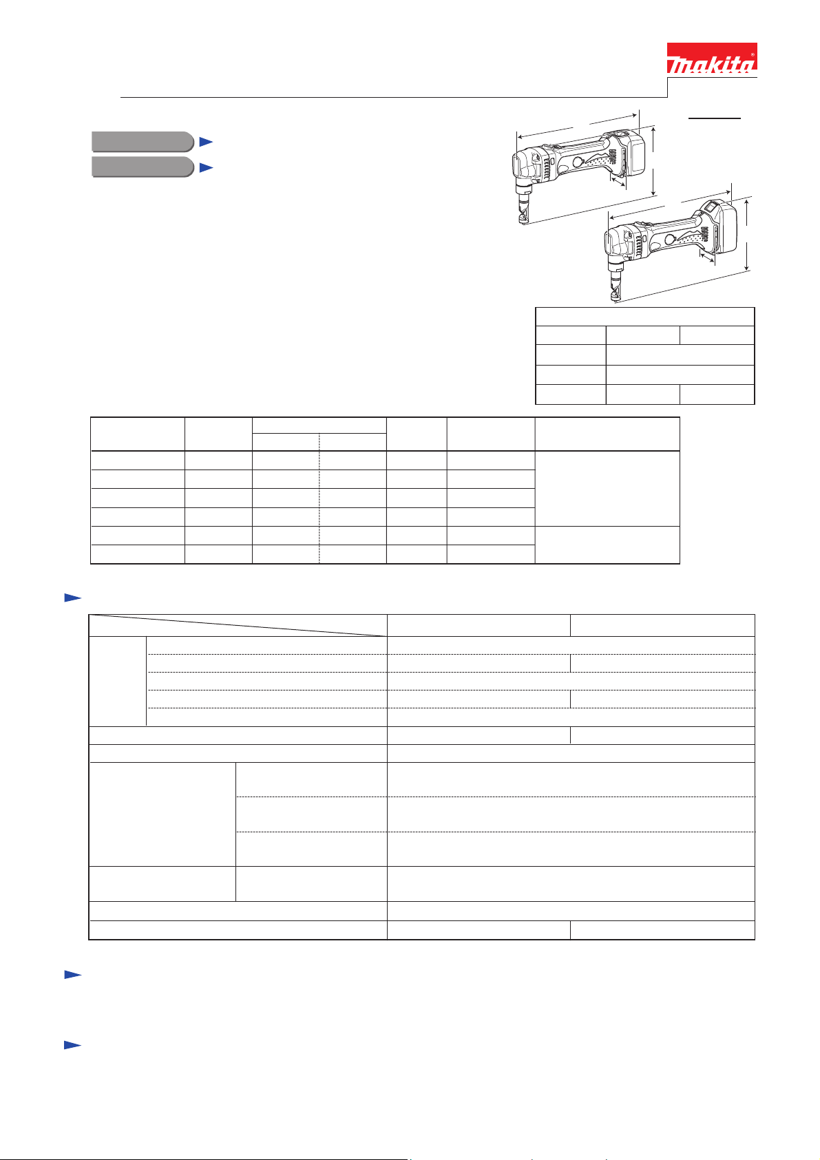
CONCEPT AND MAIN APPLICATIONS
Models BJN160 and BJN161 (LXNJ01*1) are cordless nibblers developed with
the same design concept as AC tool JN1601, featuring slim motor housing of
DC angle grinder BGA450.
Punch and die (that are the same as those of JN1601), and following 3.0Ah
Li-ion batteries provide high cutting capacity.
• BL1430 (14.4V) for BJN160
• BL1830 (18V) for BJN161 (LXNJ01*1)
Note: 1.3Ah Li-ion battery BL1415/ BL1815 cannot be used for these models.
These products will be available in the following variations.
Model No.
BJN160Z No No
BJN160RFE DC18RC Yes2
BJN161RFE DC18RC Yes2BL1830 1
LXNJ01*
All models also include the accessories listed below in "Standard equipment".
1 DC18RA No2BL1830 1
Charger
1
Battery
Type Quantity
NoNo
BL1430 1
NoNo
NoNo
No No
Battery
cover
Specification
Specification
Cell
Voltage: V
Battery
Max output (W)
No load speed: min.
Max cutting capacities:
mm (Ga)
Minimum cutting radius:
mm (")
Overload protection by current limiter Yes
Weight according to EPTA-Procedure 01/2003*2: kg (lbs)
*2 with Punch, Die and Battery
Capacity: Ah
Charging time (approx.): min.
ˉ¹=spm (strokes per minute) 1,900
Mild steel with tensile
strength up to 400N/mm²
Stainless steel with tensile
strength up to 600N/mm²
Aluminum with tensile
strength up to 200N/mm²
Cut SPCC sheet of
1.6mm (16Ga) thick
Model BJN160 BJN161 (LXNJ01*
Plastic
carrying case
No
NoBJN161Z No No
NoLXNJ01Z*
14.4 18
44
22
with DC18RC (DC18RA*1)
280 350
Inner edge: 45 (1-3/4),
Outer edge: 50 (2)
2.1 (4.6) 2.2 (4.8)
BJN161
Dimensions: mm (")
BJN160 BJN161
Length (L) 313 (12-3/8)
Width (W)
Height (H)
Offered to
All countries except
North and Central
American countries
North and Central
American countries
Li-ion
3.0
1.6 (16)
1.2 (18)
2.5 (12)
78 (3-1/16)
174 (6-7/8) 189 (7-7/16)
W
54Energy capacity: W
H
1)
Standard equipment
Punch .................... 1 Die .................... 1 Hex wrench 2.5 .................... 1 Wrench 32 .................... 1
Note: The standard equipment for the tool shown above may vary by country.
Optional accessories
Punch
Die
Battery BL1430 for Model BJN160
Battery BL1830 for Model BJN161
(LXNJ01*1)
Fast charger DC18RA (for USA, Canada, Guam, Panama, Mexico, Colombia)
Fast charger DC18RC (All countries except the countries above)
Charger DC24SC
Charger DC18SD
Automotive charger DC18SE
Page 2
P 2/ 8
Repair
CAUTION: Repair the machine in accordance with “Instruction manual” or “Safety instructions”.
[1] NECESSARY REPAIRING TOOLS
Code No. Description Use for
1R030 Bearing setting pipe 25-17.2 assembling Spur gear 31 to Crank shaft
1R032 Bearing setting plate 8.2 supporting Crank shaft when assembling Spur gear 31
1R217 Ring 22 supporting Spur gear 31 when removing Crank shaft
1R282 Round bar for Arbor 8-50 removing Crank shaft from Spur gear 31
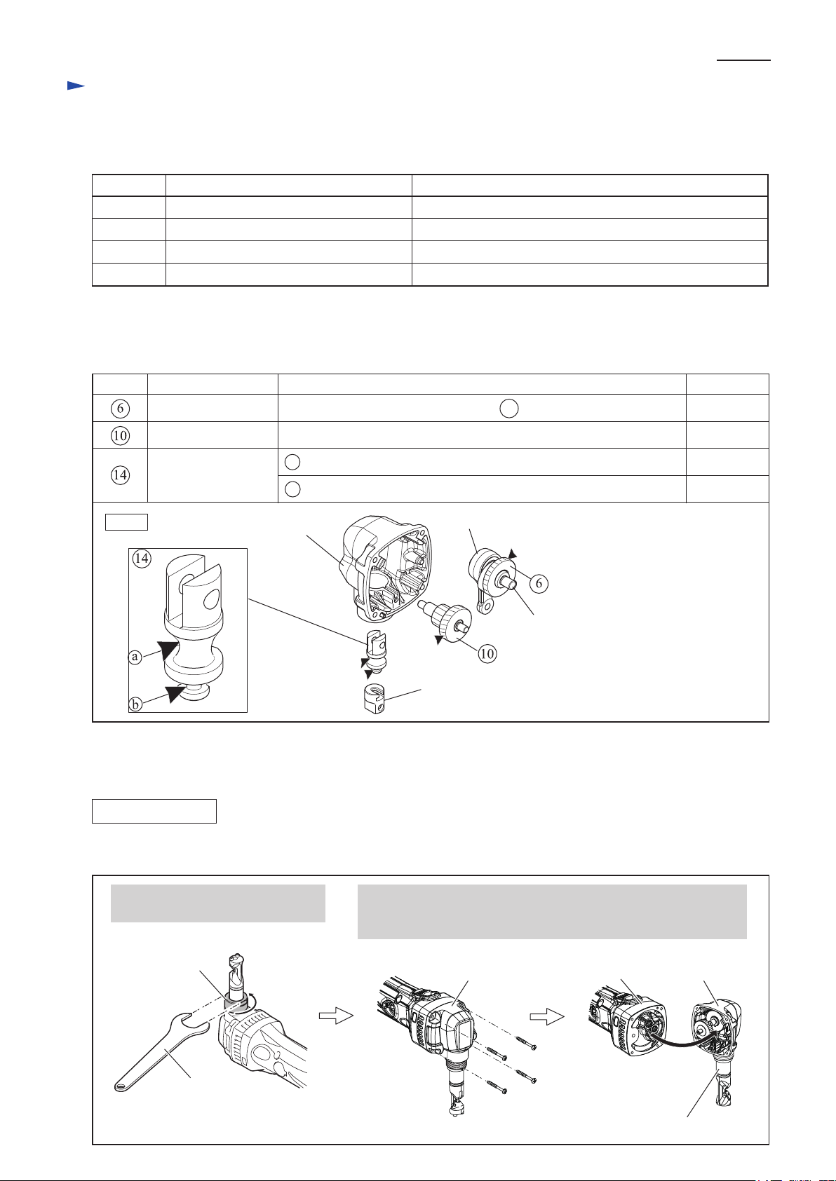
[2] LUBRICATION
Apply Makita grease FA No.2 to the following portions designated with the black triangle to protect parts and product
from unusual abrasion.
Item No. Description
AmountPortion to lubricate
Spur gear 31
Gear complete 16-36
Ram
Fig. 1
Teeth portion where the small gear of 10 engages
Teeth portion of large gear where Armature’s gear engages
a Currve of hourglass shaped portion
b narrow portion between small rim and large rim
Gear housing
complete
[3] DISASSEMBLY/ASSEMBLY
[3] -1. Gear housing complete
DISASSEMBLING
Approx. 3 g
Approx. 4 g
Approx. 1 g
Approx. 1 g
Rod
Crank shaft
Punch holder
(1) Separate Gear housing complete as drawn in Fig. 2.
Fig. 2
1. Remove Lock nut with Wrench 32
by turning it counterclockwise.
Lock nut
Wrench 32
2. Separate Gear housing complete together with Die holder section
from Gear housing cover complete by unscrewing four 4x40
Tapping screws.
Gear housing
complete
4x40 Tapping screw
(4 pcs.)
Gear housing
cover complete
Die holder section
Gear housing
complete
Page 3
Repair
[3] DISASSEMBLY/ASSEMBLY
[3] -1. Gear Housing Complete (cont.)
DISASSEMBLING
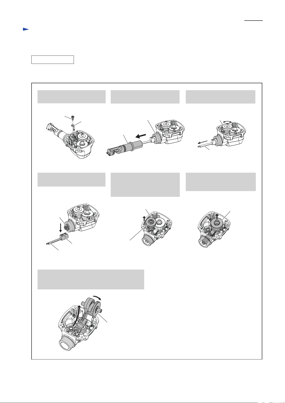
(2) Disassemble the component parts from Gear housing complete as drawn in Fig. 3.
Fig. 3
P 3/ 8
1. Remove Stopper by unscrewing
Bind CT4x12 Tapping screw.
Bind CT4x12 Tapping
screw
Stopper
4. Remove Punch holder together
with Punch from Ram.
Ram
2. Pull off Die holder section from
Gear housing complete.
Gear housing
complete
Die holder
section
5. Remove Gear complete 16-36
from Gear housing complete.
Note: Be careful not to lose
Flat washer 6.
Gear complete 16-36
3. Set Punch to the lowest position
by turning Gear complete 16-36.
Gear complete
16-36
Punch
6. Lift up Spur gear 31 until the
space for twisting Spur gear 31
and Crank shaft is reserved.
Spur gear 31
Punch holder
Punch
7. Remove Super gear 31 together with Crank section
while turning them 90°.
Note: Be careful not to lose Flat washer 8.
Flat washer 6
Flat washer 8
Page 4

Repair
[3] DISASSEMBLY/ASSEMBLY
[3] -1. Gear Housing Complete (cont.)
DISASSEMBLING
(3) Disassemble Spur gear 31 and Crank section as drawn in Fig. 4.
Fig. 4
P 4/ 8
1. Separate Ram by removing Pin 6, and then
remove Spur gear 31 together with Crank
shaft from Rod.
Crank shaft
Rod
Ram
Pin 6
ASSEMBLING
(1) Assemble Spur gear 31 and Crank section as drawn in Fig. 5.
Fig. 5
Spur gear 31
Crank shaft
Spur gear 31
2. Place Super gear 31 and Crank shaft on 1R217.
Then, press Crank shaft down with 1R282.
Note: Be careful not to lose Woodruff key 3.
1R282
1R217
Crank shaft
Woodruff key 3
1. Set Woodruff key 3 to Crank shaft.
And then, insert the slim end of
Crank shaft into Spur gear 31
from its stepped side while fitting
Woodruff key 3 to the groove of
Spur gear 31.
groove
Spur gear 31
stepped side
Crank shaft
slim end
Woodruff key 3
(2) Assemble Spur gear 31, Crank section and the other component parts to Gear housing complete by reversing
the disassembly procedure. (Refer to Fig. 3)
Note: Do not forget to mount Flat washer 6 to Gear complete 16-36. (Refer to the center drawn in Fig. 3)
2. Put Super gear 31 and Crank
section onto 1R032.
Then, Press the Gear down
with 1R030 until it stops.
1R030
Spur gear 31
Crank shaft
1R032
3. Insert Crank shaft into Rod, and
assemble Ram to the other end
of Rod with Pin 6.
Note: Do not forget to mount
Flat washer 8.
Crank shaft
Rod
Flat washer 8
Spur gear 31
Ram
Pin 6
Page 5

Repair
[3] DISASSEMBLY/ASSEMBLY
[3] -2. Armature
DISASSEMBLING
(3) Disassemble Carbon brushes and Armature as drawn in Fig. 6.
Fig. 6
P 5/ 8
1. Remove Holder cap cover by levering it up
with a slotted screwdriver.
Holder cap cover
3. Separate Gear housing complete from Housing set by unscrewing
four 4x20 Tapping screws.
Armature
2. Remove Brush holder caps and Carbon brushes.
Brush holder caps
Holder cap cover
Carbon brush
Carbon brush
Holder cap cover
4. Pull off Armature from
Housing set.
Gear housing
4x40 Tapping screw
(4 pcs.)
complete
Armature
[3] -3. Yoke unit
ASSEMBLING
Assemble Yoke unit to Housing L while aligning the notch of Yoke unit to the projection on Housing L. (Fig. 7)
Fig. 7
Yoke unit
Housing L
notch
projection
Page 6

Repair
[3] DISASSEMBLY/ASSEMBLY
[3] -4. Die and Punch
DISASSEMBLING
(1) Remove Lock nut with Wrench 32 by turning it counterclockwise. (See the left drawn in Fig. 2)
(2) Disassemble Die and Punch as drawn in Fig. 8.
Fig. 8
P 6/ 8
1 Pull off Die holder from Gear housing complete.
2 Remove Punch by loosening M5x8 Hex socket
set screw with Hex wrench.
2
Punch
Punch
holder
M5x8 Hex socket set screw
ASSEMBLING
Assemble Punch and Die holder as drawn in Fig. 9.
Fig. 9
Hex
wrench
1
Die holder
3
Die
M3x12 Hex socket
head screw (2 pcs.)
3 Remove Die from Die holder
by unscrewing two M3x12
Hex socket head screws.
1. Insert Punch into Punch holder until it stops
while aligning its concave portion with the screw
hole of Punch holder.
And tighten M5x8 Hex socket set screw.
concave for fitting the screw end
screw hole of
Punch holder
of M5x8 Hex socket set screw
M5x8 Hex socket
set screw
2. Assemble Die holder to Gear housing complete
while aligning the window of Die holder to
the stepped portion of Punch.
Punch
Die holder
window of Die holder
stepped portion of Punch
Page 7

Circuit diagram
Fig. D-1
Color index of lead wires' sheath
Black
Red
P 7/ 8
Switch
Terminal
Wiring diagram
Fig. D-2
Controller
Line filter
Line filter is not used
for some countries
Setting Endbell Complete on Housing L
Set Endbell complete on Housing L as follows:
* Face its Lead wires to the belly side of Housing L.
* Face Lead wire (black) to Housing L.
Endbell
complete
LED Circuit
Top side
Rear side Front side
Lead wire (black)Lead wire (red)
Belly side
Page 8

Wiring diagram
Fig. D-3
Fig. D-4
P 8/ 8
Wiring to Switch
Connect Insulated terminals to Switch while facing their wire
connecting portions to the opposite side of Switch button.
Wire connecting portions
of Insulated terminal
Switch button
Wiring in Housing L
Pass Lead wires of Controller
through the space between
Housing L and Controller.
Terminal Endbell complete
Lead wires of Controller
Switch
Controller
Line filter
Put Line filter in the
space as drawn above
if it is used.
Set Switch to Housing L as follows:
* Face Switch button to Controller side.
* Face Insulated terminals connected side
(See Fig. 3D.) to Housing L.
LED Circuit
Lead wire holder
Guide lead wires of LED circuit
along the wall side of Housing L
as drawn above. And then fix
the wires with Lead wire holder.
Wire connecting portions
Connect Flag connectors
so that their wire connecting
portions are located over
the mark of + - poles.
 Loading...