

Page 1
Models No.
Description
PRODUCT
P 1/ 16
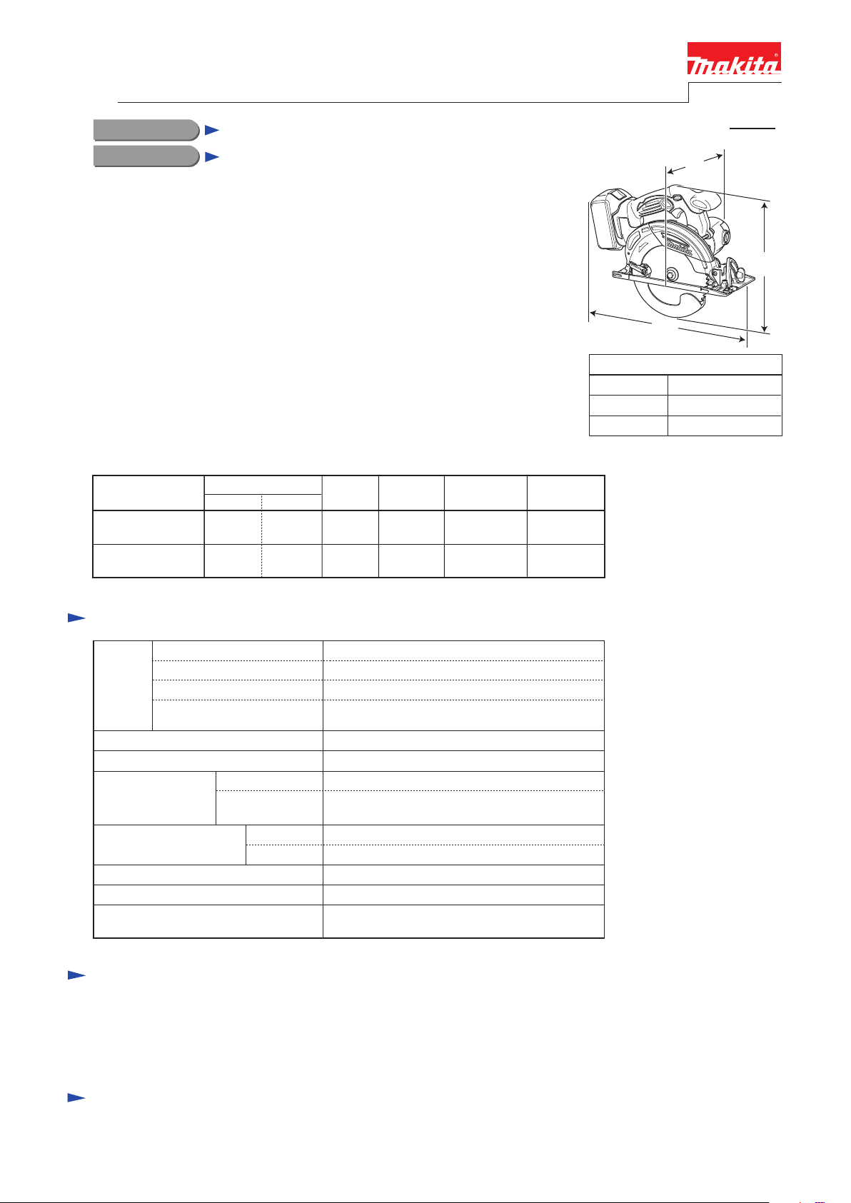
Model BHS630 is a 165mm (6-1/2") Cordless Circular Saw powered by
18V/3.0Ah Li-ion battery Model BL1830.
Its main features are:
• Aable to cut up to 66mm (2-5/8") thick wood with a single stroke,
which no competitors’ 18V models can do.
• In spite of compact and lightweight design, performs the same smooth
and comfortable cutting as AC circular saws.
• Compatible with 18V Li-ion battery of BL1830 equipped with the battery
protection circuit designed to protect the battery from damages due to
overdischarge, high temperature or overload current.
• High maneuverability provided by Good tool balance, Twin LED light,
Blower function and Fine parallel adjustment of base plate.
Dimensions: mm (")
Width (W)
Height (H)
Length (L) 346 (13-5/8)
220 (8-5/8)
247 (9-3/4)
Note: The standard equipment for the tool shown above may vary from country to country.
BHS630 (LXSH01*1)
165mm (6-1/2") Cordless Circular Saw
TCT Saw blade 165mm (6-1/2") .................................. 1
Hex wrench 5 ................................................................ 1
Rip fence ....................................................................... 1
Dust nozzle (for European countries only) ................... 1
Battery
Blade size: mm (")
Electric brake
Max cutting capacities:
mm (")
Diameter
Hole diameter
at 45°
No load speed: min-1=rpm
Cell
Voltage:V
Capacity:Ah
Li-ion
18
3.0
Weight according to
EPTA-Procedure 01/2003*2: kg (lbs)
*Includes TCT Saw Blade, Battery BL1830 and Dust nozzle
3.5 (7.7)
Yes
Job light Yes (Twin LED light)
North America: 15.88 (5/8)
All countries except North America: 20
46 (1-13/16)
at 0° 66 (2-5/8)
3,100
165 (6-1/2)
Max output (W) 730
This model is available in the following variations.
Note: 1.3Ah Li-ion battery of BL1815 cannot be used for this model.
T
ECHNICAL INFORMATION
CONCEPT AND MAIN APPLICATIONS
Specification
Standard equipment
Optional accessories
L
H
W
*1 Model number for North and Central American countries
All models also include the accessories listed below in "Standard equipment".
Model No.
Type Quantity
Charger
Plastic
carrying case
Battery
cover
Battery
BL1830
---
DC18RC Yes
BHS630Z
(LXSH01Z)
2 1
--- ---
Housing
color
Makita-blue
Makita-blue--- ---
BHS630RFE
(LXSH01)
Battery BL1830
165mm (6-1/2") TCT Saw Blades
Dust nozzle
Rip fences
Fast charger DC18RC
Charger DC18SD
Charger DC24SC
Automotive charger DC18SE
Safety goggles
Guide rail adapter
Various parts of guide rail
Charging time (approx.):
min.
15/ 22
with DC18RC
Page 2
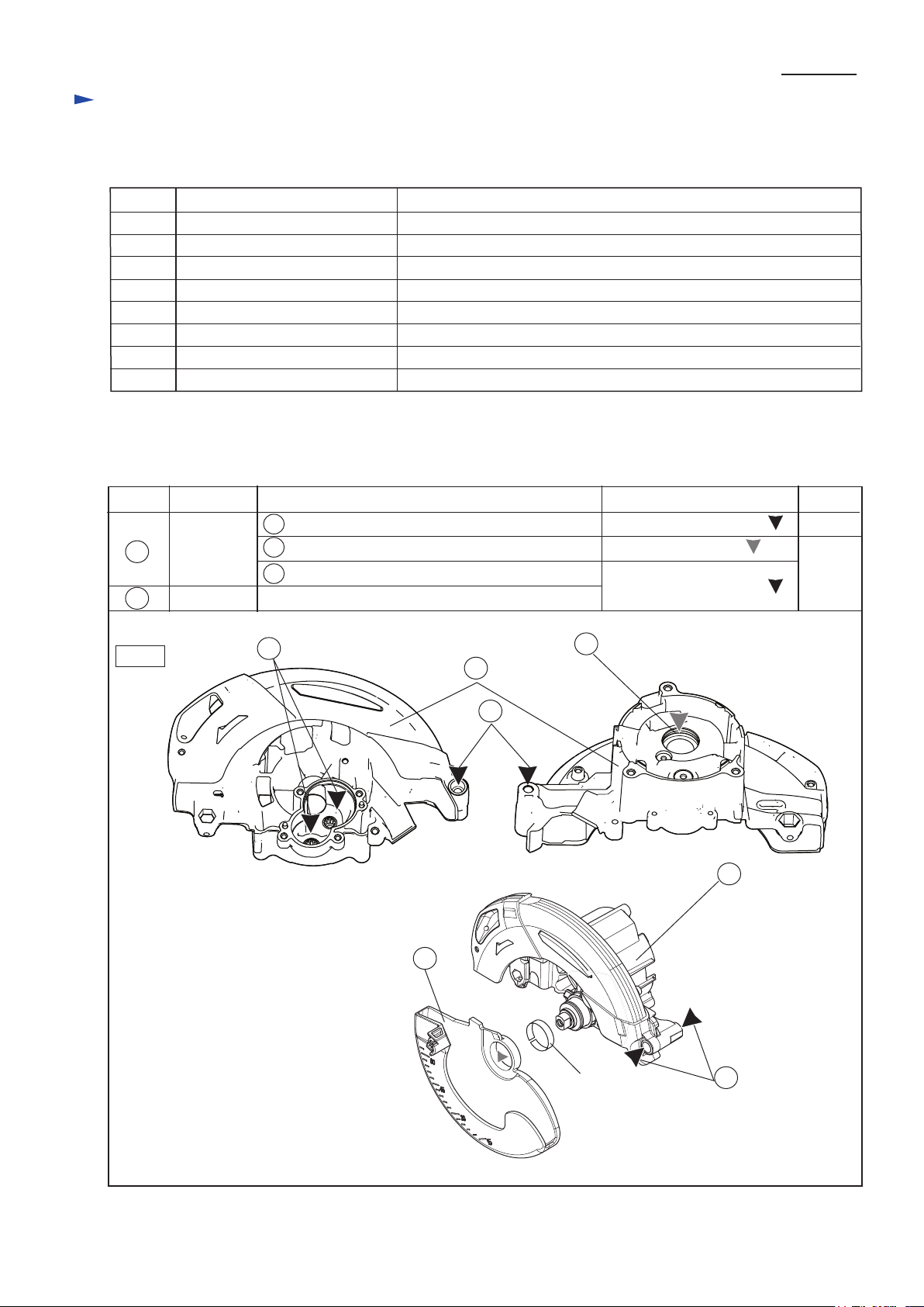
CAUTION: Repair the machine in accordance with “Instruction manual” or “Safety instructions”.
[1] NECESSARY REPAIRING TOOLS
[2] LUBRICATIONS
Fig. 1
Code No. Description Use for
1R003 Retaining ring S pliers ST2N removing / mounting Retaining ring WR-26
1R031 Bearing setting pipe 28-20.2 holding Bearing box when removing Helical gear 24
1R208 90 degree set square adjusting the angle of Saw blade to 90 Degrees
1R212 Tip for Retaining ring pliers attachment to 1R003
1R263 Bearing extractor removing Blade cover
1R269 Bearing extractor removing Ball bearings
1R291 Retaining ring S & R pliers removing Retaining ring S-10 from Spindle
1R361 Bearing retainer tightening tool removing / Mounting Bearing retainer 14-23
Item No.
60
A
A Gear room where Gears engage each other
B O ring 24 Lubricant VG100
a little
8 gMakita grease SG No.0
B
Apply the following grease and Lubricant to the portions pointed with triangles to protect parts and product
from unusual abrasion.
Description
Blade case
complete
Lubricant
Safety cover
AmountPortion to lubricate
Makita grease SG No.0
40
60
Thickness
Ring
C Pivot portion where Angular guide contacts
Inside of Ring portion where Thickness ring contacts
40
C
60
C
Repair
P 2/ 16
Page 3
M6x8 Hex socket head
set screw
Fig. 2
Fig. 3
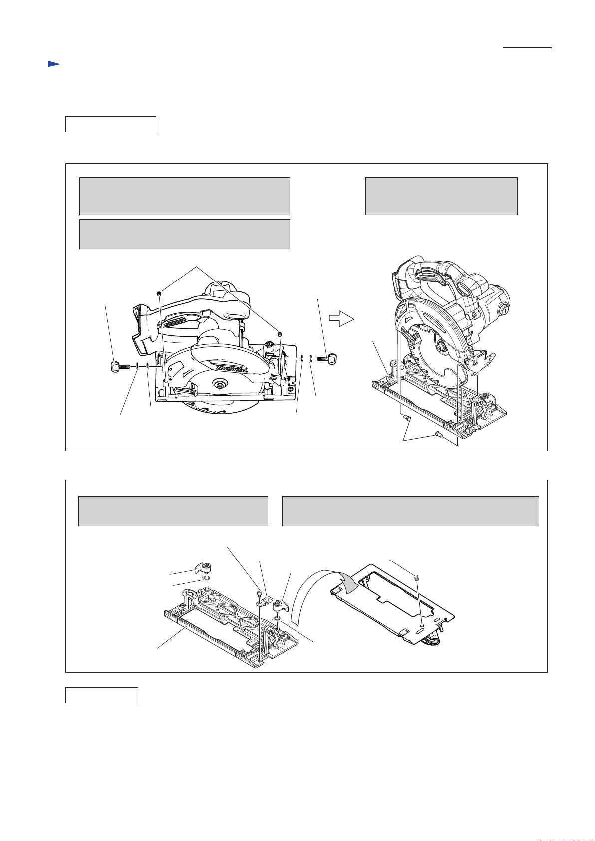
[3] DISASSEMBLY/ASSEMBLY
[3]-1. Base
DISASSEMBLING
M6x6 Hex socket head set Screw
1. Remove M6x20 Thumb screw, Spring washer 6,
and Flat washer 6 from Angular guide side and
Depth guide side.
2. Remove M6x6 Hex Socket Head Set Screw
from Angular guide side and Depth guide side.
M6x20 Thumb
screw
Shoulder pin 6-7
Base
Remove the parts drawn below from Base.
And then, replace the Base with the new one.
Do not forget to remove M6x8 Hex socket head set screw for
adjusting the angle of saw blade from the reverse side of Base.
Base
Note in Assembling
1. After mounting Lock lever, its adjustment is required to obtain the correct lock position for guide rule, mounted.
to Base. See “[3]-2. Lock Lever” .
2. After mounting Base to the machine, adjustment of angle of saw blade to the Base is required.
See “[4] Adjustment”
Take the reverse step of Disassembling. Refer to Fig. 3, Fig. 2.
Base can be separated from the machine as drawn in Figs. 2 and 3.
3. Remove Shoulder pin 6-7.
Now Base complete is separated
from the machine.
Spring
washer 6
Flat
washer 6
Lock lever
Torsion
spring 11
Torsion spring 11
Lock lever
Spring
washer 6
Flat
washer 6
M6x20 Thumb
screw
M4x8 Pan head screw
Top guide
ASSEMBLING
Repair
P 3/ 16
Page 4
M6x10 Hex bolt
Lock lever
Lock lever
3. Set Lock lever to M6x10 Hex bolt, while hooking Torsion spring 11
with its long Arm to the Rib of Base.
4. Push the Lock lever to engage it with M6x10 Hex bolt at the
convenient position for loosening and locking.
And secure the Lock lever with Stop ring E-6.
Note:
Do not yet push Lock lever to the
position where it is in this step.
Otherwise, Lock lever engages
unintentionally with M6x10
Hex bolt, before obtaining the
convenient position for operating
Lock lever.
Fig. 4
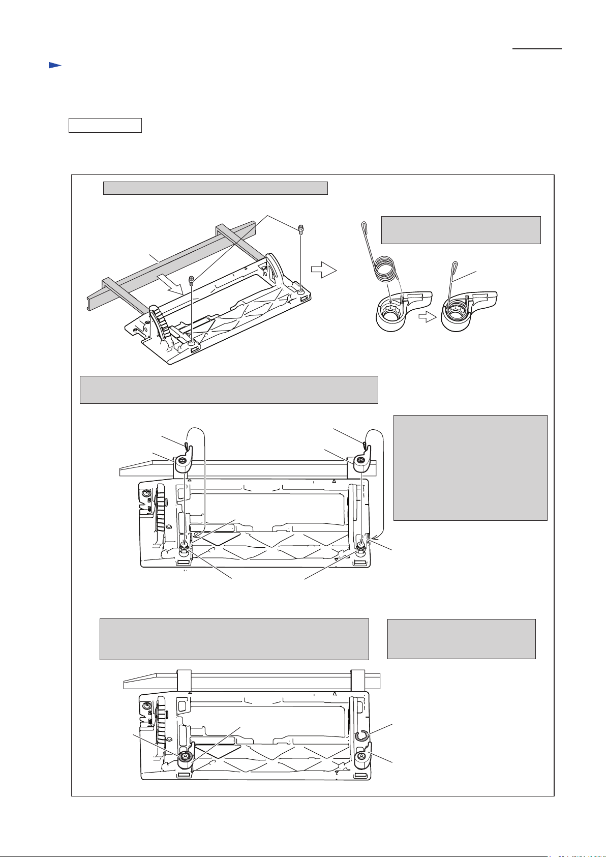
[3] DISASSEMBLY/ASSEMBLY
[3]-2. Lock Lever
ASSEMBLING
1. Tighten M6x10 Hex bolt to fix Guide rule to Base.
Guide Rule
M6x10 Hex bolt
2. Set Torsion spring 11 to Lock lever
as drawn in below.
Base
Assemble Lock lever to Base, and adjust to obtain the convenient lock position as drawn in Fig. 4.
Long arm of
Torsion spring 11
Long arm of
Torsion spring 11
Rib
Rib
long arm of
Torsion spring 11
Lock lever
Lock lever
Stop ring E-6
5. Make sure that the reassembled
Guide rule is locked with the
Lock lever at the same position.
Stop ring E-6
Repair
P 4/ 16
Page 5
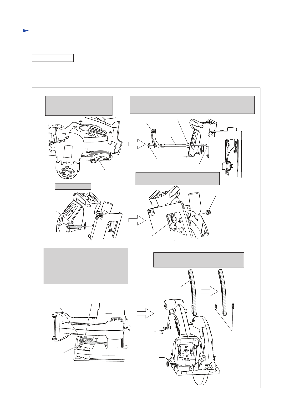
Fig. 5
[3] DISASSEMBLY/ASSEMBLY
[3]-3. Depth Guide
DISASSEMBLING
Depth guide is joined to the Machine at the Handle section, and to Base at Rear angular guide.
Separate Depth guide by disassembling from Handle section and from Rear angular guide as drawn in Fig. 5.
1. Loosen Lever 55 by turning
toward the direction designated
with arrow.
2. Take off Stop ring E-8, and remove M6x85 Hex bolt, by
employing Lever 55 as a wrench. And remove Flat washer 6.
Now, Depth guide is disjoined from the machine.
Lever 55
Lever 55
Flat washer 6
M6x85
Hex bolt
Stop ring E-8
Pipe 6
Pipe 6
M6 Hex nut
3. Remove Pipe 6.
4. Remove M6 Hex nut, loosening M5x8
Hex socket head set screw.
5. Remove M4x20 Hex socket head bolt
and M4-7 Hex lock nut, pulling down
Base to the position in which they can
be easily removed. Now, Depth guide is
disjoined both from the machine
and Rear angular guide.
Base
M5x8 Hex socket head
set screw ( No need to remove completely.)
M4x20 Hex socket
head bolt
Rear angular
guide
M4-7 Hex
lock nut
Collar
Depth guide
6. Disassemble Depth guide, and remove two
Collars from the both side of Depth guide.
Repair
P 5/ 16
Page 6

Fig. 6
[3] DISASSEMBLY/ASSEMBLY
[3]-3. Depth Guide
ASSEMBLING
Fig. 7
1. Mount M6 Hex nut, facing its concave side to M5x8 Hex socket head set screw side.
So, the Hex nut can be fixed with M5x8 Hex socket head screw firmly in Blade case.
This concave portion
accepts the end of
M5x8 Hex socket head
set screw.
M5x8 Hex socket head set screw
45 mm
4. The distance between the bottom of Base and
the bend of Lever 55 has to be approx 45 mm,
when the machine is adjusted to obtain max.
cutting depth.
1. Insert Pipe 6 into the hole of
Motor housing complete
at the Handle portion.
2. Passing M6x85 Hex bolt through Flat
washer 6, insert the Hex bolt into the
Pipe 6, and pass through two Collars
and Depth guide.
3. Setting the machine to the
deepest position (max. cut
mode), drive the M6x85 Hex
bolt to the M6 Hex nut,
mentioned in Fig. 6
4. Proceed the assembling as drawn in Fig. 7.
1. Assemble Depth guide to Rear angular guide by tightening with M4x20 Hex socket head bolt and M4-7 Hex lock nut.
Refer to the bottom left illustration in Fig. 5.
2. Set Collar to the both side of the Depth guide. Refer to the bottom right illustration in Fig. 5.
3. Mount M6 Hex nut to Blade case as illustrated in Fig. 6.
M6 Hex nut
M6 Hex nut
Pipe 6
Flat Washer 6
M6x85 Hex bolt
Pipe 6
Repair
P 6/ 16
Page 7

Fig. 8
[3] DISASSEMBLY/ASSEMBLY
[3]-4. Angular Guide
DISASSEMBLING
DISASSEMBLING
ASSEMBLING
1. Remove M5 Pan head screw with Screwdriver, while locking M5-8 Nut with wrench 8.
Now, Angular guide is removed from the machine.
Angular guide is fixed to the machine at the following 3 positions.
1. at the hinge portion fixed with Shoulder pin 6-7 and M6x6 Hex socket head set screw
2. at Angular plate on Base with M6x20 Thumb screw, Flat washer 6 and Spring washer 6
3. at Blade case section with M5 pan head screw and M5-8 Nut.
(1) Make Angular guide free at hinge portion and Angular plate portion as drawn in Fig. 2.
(2) Make the Angular plate free from the Blade case section as drawn in Fig. 8.
Wrench 8
M5-8 Nut
M5-8 Nut
M5 Pan head screw
Angular guide
Disassemble Cover by unscrewing 4x20 Tapping screws.
Now, Connectors and LED come into your sight. Disconnect Connectors. So, LED is replaced.
Blade case section
[3]-5. LED and Motor Section
Assemble Angular guide, referring to Fig. 2.
The machine is joined to Base at the following 2 positions.
1. at the hinge portion of Blade case ( at the front side of Blade case) with Angular guide
2. at the Handle section of Motor housing complete with Depth guide
Angular guide
M5 Pan head screw
(1) Remove Lever 55 and M6x85 Hex bolt as per the top right drawing in Fig. 5.
Now the machine is free from Depth guide.
(2) Make the machine free from Angular guide as illustrated in Fig. 8.
Now the machine is separated from Base completely. And disassemble LED as drawn in Fig. 9.
Fig. 9
Repair
P 7/ 16
Cover
LED
Connector
4x20 Tapping screw
Connector
LED
Page 8

Fig. 10
Fig. 11
[3] DISASSEMBLY/ASSEMBLY
[3]-5. LED and Motor Section
DISASSEMBLING
1. Remove Carbon brush and unscrew three M5x33
Pan head screws.
2. Separate Blade case section from Motor housing complete.
3. From Blade case section, Armature, Shaft lock and
Compression spring 6 are removed.
4. Disassemble Baffle plate and Yoke unit by unscrewing
two 4x65 Tapping screws.
(3) Armature and Yoke unit can be replaced as drawn in Fig. 10.
Carbon brush
M5x33 Pan
head screw
Armature
Compression
spring 6
Baffle plate
Yoke unit
(1) Assemble Yoke unit to Motor housing complete as illustrated in Fig. 11.
(2) Assemble Motor section by tasking the reverse step of Disassembling. Refer to Fig. 10.
4x65 Tapping screw
Shaft lock
Yoke unit
Note in Assembling:
Notch A and Notch B are reversible.
Note in Assembling:
Do not forget to assemble Shaft lock and Compression spring 6. Refer to the lower left drawing in Fig. 10.
Insert Yoke unit into Motor housing complete,
while aligning Notch A to Rib A.
So, Yoke unit is exactly mounted to Motor
housing complete, by fitting Notch B to Rib B.
Motor housing
complete
ASSEMBLING
Rib A
Rib B
Notch A
Notch B
Repair
P 8/ 16
Page 9

Fig. 12
[3] DISASSEMBLY/ASSEMBLY
[3]-6. Blade Case Complete
DISASSEMBLING
1. Remove retaining ring WR-26 and Flat washer 26.
Use 1R003 equipped with Claw of 1R212,
when removing retaining ring WR-26.
2. Remove Safety cover, Tension spring 4 and Thickness ring.
3. Remove the parts of LED section,
Rubber sleeve 6, M5-8 Hex socket
head set screw and M6 Hex nut.
4. Remove Bearing box (Gear section)
by unscrewing four M4x16 pan head
screws.
(1) Remove Lever 55 and M6x85 Hex bolt as per the top right drawing in Fig. 5.
Now the machine is free from Depth guide.
(2) Make the machine free from Angular guide as drawn in Fig. 8.
Now the machine is separated from Base completely.
(3) Separate Blade case as per the upper left, upper right and lower left drawings in Fig. 10.
(4) Disassemble Safety cover and Gear section from Blade case as drawn in Fig. 12.
Cover
Retaining
ring WR-26
<Note in Disassembling>
Hold the Retaining ring with your gloved hand
so that it does not spring when removing.
Flat washer 26
Safety cover
Tension spring 4
Thickness ring
Connector box
Connector
LED
Gasket
Gear section
M4x16 Pan
head screw
(4pcs.)
4x20 Tapping screw
Rubber
sleeve 6
M6 Hex nut
M5-8 Hex socket
head set screw
LED section
Repair
P 9/ 16
Page 10

Fig. 14
[3] DISASSEMBLY/ASSEMBLY
[3]-6. Blade Case Complete
ASSEMBLING
Fig. 13
(1) Take the reverse step of Disassembling. Refer to Figs. 13 and 12.
(5) Remove Blade cover and Duct from Blade case complete as drawn in Fig. 13.
1. Remove two 4x12 Tapping screws
with which Blade cover and Duct
are secured to Blade case complete.
2. Remove Blade cover from Blade
case complete by levering up with
1R263, inserted into the gap between
Blade case complete and Blade cover.
3. Remove Duct from Blade
case complete.
Note in Assembling:
Tension spring 4 has to be connected to Safety cover and Blade case as drawn in Fig. 14.
DISASSEMBLING
Blade cover
1R263
Duct
Duct
Tension spring 4
Blade case
Safety cover
Pass the Hook from Gear section side to Blade case.
Pass the Hook from Blade side to Gear section side.
Blade side
Gear section side
Repair
P 10/ 16
Page 11

[3] DISASSEMBLY/ASSEMBLY
[3]-7. Bearing Box (Gear Section)
DISASSEMBLING
ASSEMBLING
In case of repairing of Bearing box (Gear section) singly, no need to separate the machine from the Base.
(1) Remove Safety cover as per the upper left and upper right drawings in Fig. 12.
(2) Remove Bearing box (Gear section) from Blade case complete as per the lower right drawing in Fig. 12.
(3) Now the Bearing box can be disassembled as drawn in Fig. 15.
Helical gear 39
Helical gear 24
Rubber ring 10
Bearing box
Spindle
Helical gear 17
Ball bearing
606ZZ
Flat washer 7
1. Disassemble Rubber ring 10, Ball bearing 606ZZ
Helical gear 17, Helical gear 39 and Flat washer 7.
Spindle, Ball bearing 6900DDW, Helical gear 24
are still in Bearing box, which are disassembled
in the next step.
2. Disassemble Retaining ring S-10 from Spindle.
And then, remove Spindle with Arbor press,
setting Bearing box on 1R031.
The Ball bearing 6900DDW has been broken in
this step.
Spindle
Retaining ring S-10
Spindle
3. Helical gear 24, Ring 10 are removed from Bearing box.
In this step, Ball bearing 6900DDW is still in Bearing box.
1R031
Bearing retainer 14-43
for securing Ball bearing
6900DDW
Helical
gear 24
Ring 10
Spindle
5. Inserting Spindle into Ball bearing 6900DDW
as illustrated below, push the Ball bearing with
the Spindle. So, Ball bearing 6900DDW is
removed from Bearing box.
Bearing
retainer 14-43
1R361
4. Set 1R361 by fitting its Claw to the Groove of
Bearing retainer 14-43.
And turn it counter clockwise. Now Bearing
retainer 14-43 is removed from Bearing box.
Spindle
Ball bearing
6900DDW
Ball bearing
6900DDW
Ball bearing 6900DDW
Take the reverse step of Disassembling. Refer to Fig. 15 and Fig. 12.
Note in Assembling:
Assemble fresh Ball bearing 6900DDW instead of the removed one, because the Ball bearing has been broken when
removing Spindle from Bearing retainer 14-43.
Fig. 15
Repair
P 11/ 16
Page 12

[3] DISASSEMBLY/ASSEMBLY
[3]-8. Lock Off Lever, Switch Lever
ASSEMBLING
Compression spring 4
Compression spring 4
Note in Assembling:
Both Compression springs are interchangeable.
1. Compression spring 4 has to be assembled
deeply and firmly to Switch lever and Lock
off lever as drawn below.
Switch lever
Lock off lever
Lock off lever
Switch lever
2. Set Lock off lever Compression spring 4 and
Switch lever to the Handle at the position
drawn below.
Handle
Assemble Switch lever and Lock off lever to Handle as illustrated in Fig. 16.
Fig. 16
Repair
P 12/ 16
Page 13

[4] ADJUSTMENT
[4]-2. Adjusting Accuracy of Parallel of Base to Saw blade
Mounting Saw blade to the machine, set the machine to the lowest possible position to obtain the max. cut depth.
But, do not attach Battery to the machine.
Adjust accuracy of 90 degree cut as drawn in Fig. 18.
Following two kinds of adjustment screws are used in this product.
1. M6x8 Hex socket head set screw for adjusting Accuracy of 90 degrees .
2. M5x8 hex socket head set screw for adjusting Accuracy of Parallel of Base to saw blade
See the following drawing in Fig. 17.
Mounting Saw blade to the machine, set the machine to the lowest possible position to obtain the max. cut depth.
But, do not attach Battery to the machine.
Adjust accuracy of parallel of Base to saw blade as drawn in Fig. 19.
Fig. 18
Fig. 18
Fig. 17
M6x8 Hex socket
head set bolt
Apply triangular rule as per the illustration
and adjust the accuracy of right angle by turning
M6x8 Hex socket head set bolt with hex wrench,
until the two sides of the adjusting jig fit to Base
and saw blade completely.
1. M6x8 Hex socket head set screw
for adjusting accuracy of 90 degree
of Base to saw blade
2. M5x8 Hex socket head set screw
for adjusting accuracy of parallel
of Base to saw blade
Triangular rule or 1R208
Hex wrench
[4]-1. Adjusting Accuracy of 90 degree cut
Base
Rear side
of Base
1. Loosen M5x8 Hex socket head set screw
with Hex wrench a little bit.
2. Apply square to the machine as per the
illustration.
3. Adjust by moving the rear side of base,
until the Square fits both to the saw blade
and the front edge of base.
M5x8 Hex socket
head set screw
Square
Saw blade
Front edge of
Base
Repair
P 13/ 16
Page 14

Circuit diagram
P 14/ 16
White
Yellow
Color index of lead wires' sheath
Black
Red
Controller
Terminal
Handle section
Motor housing
Blade case
Brush holder
LED Job
Light
Switch for
LED job light
ON / OFF
Switch
Fig. D-1
Page 15

Fig. D-2
to ON/OFF Switch in Handle
Opening for Lead wires
Opening for Lead wire
Lead wire holder
Lead wire holder
Put Lead wires for
connecting to Connector
inside the Rib.
Brush holder
Brush holder
Fix Lead wires (black), (white) of Brush holders in
Lead wire holder here so as not to make any slacks
between Opening and the lead holder.
Fix Brush holder’s Lead wires
in Lead wire holders.
Pass the Lead wires through the opening
to Blade case side.
Lead wire
holder
Wiring of Brush holder’s Lead wires
Wiring in Handle
Fig. D-3
Fix the following Lead wires in these Lead wire holders.
* Lead wre (white) between ON/OFF switch and Switch unit of LED
* Lead wire (black) between Controller and Connector
Connector
See Fig. D-4 in
the next page.
Wiring diagram
P 15/ 16
Page 16

Fig. D-4
Put the extra portion of Lead
wires in Connector box.
Fix the Lead wires (black),
(red) from Handle in
Lead wire holder.
Do not put the lead wires on
rib and the place designated
with gray color.
Wiring of LED Lead wires
in Blade case and Connector box
Connector
Connector box
LED
Wiring diagram
P 16/ 16
 Loading...