


Makita 6837 Manual
|
|
|
|
|
|
|
|
|
|
|
GB |
Auto Feed Screwdriver |
Instruction Manual |
|
|
|
|
|
|
|
|
Visseuse à recharge automatique |
Manuel d’instructions |
|
|
F |
|||
|
|
|
|
|
|
|
Magazin-Schnellbauschrauber |
Betriebsanleitung |
|
|
D |
|||
|
|
|
|
|
|
|
Avvitatore ad auto-alimentazione |
Istruzioni per l’uso |
|
|
I |
|||
|
|
|
|
|
|
|
Schroef automaat |
Gebruiksaanwijzing |
|
|
NL |
|||
|
|
|
|
|
|
|
Atornillador autoalimentado |
Manual de instrucciones |
|
|
E |
|||
|
|
|
|
|
|
|
Chave de parafusos com alimentação |
Manual de instruções |
|
|
P |
|||
|
|
automática |
|
|
|
|
|
||
|
|
Magasin Skrueautomat |
Brugsanvisning |
|
|
DK |
|||
|
|
|
|
|
|
|
Skruvdragare med automatisk matning |
Bruksanvisning |
|
|
S |
|||
|
|
|
|
|
|
|
Skrutrekker med automatisk tilførsel |
Bruksanvisning |
|
|
N |
|||
|
|
|
|
|
|
|
Makasiini-pikaruuvinväännin |
Käyttöohje |
|
|
SF |
|||
|
|
|
|
|
|
|
Γεµιστήρας τα υ ιδωτήρας |
δηγίες ρήσεως |
|
|
GR |
|||
|
|
|
|
|
6837
 1 2
1 2
1 |
4 |
5 |
3 |
9 |
10 |
|
11 |
|
4 |
5 |
|
|
13 |
|
14 |
7 |
|
2 |
|
|
|
|
3 |
2 |
|
|
|
|
|
7 |
8 |
6 |
|
|
|
|
|
|
|
4 |
|
|
|
|
5 mm |
|
10 |
|
|
|
|
|
4 |
|
|
|
|
B |
12 |
|
|
A |
|
|
|
|
|
6 |
|
|
|
15 |
|
|
|
16 |
|
|
|
8 |
|
|
|

17 |
9 |
18 |
11 |
13 |
14 |
10 |
19
12
|
20 |
13 |
14 |
|
21 |
15 |
16 |
|
3 |

 10
10
22

 15 mm
15 mm
17 |
18 |
 23
23  24
24
19
4

Symbols
The followings show the symbols used for the tool. Be sure that you understand their meaning before use.
Symboles
Nous donnons ci-dessous les symboles utilisés pour l’outil. Assurez-vous que vous en avez bien compris la signification avant d’utiliser l’outil.
Symbole
Die folgenden Symbole werden für die Maschine verwendet. Machen Sie sich vor der Benutzung unbedingt mit ihrer Bedeutung vertraut.
Symboli
Per questo utensile vengono usati i simboli seguenti. Bisogna capire il loro significato prima di usare l’utensile.
Symbolen
Voor dit gereedschap worden de volgende symbolen gebruikt. Zorg ervoor dat u de betekenis van deze symbolen begrijpt alvorens het gereedschap te gebruiken.
Símbolos
A continuación se muestran los símbolos utilizados con esta herramienta. Asegúrese de que entiende su significado antes de usarla.
Símbolos
O seguinte mostra os símbolos utilizados para a ferramenta. Certifique-se de que compreende o seu significado antes da utilização.
Symboler
Nedenstående symboler er anvendt i forbindelse med denne maskine. Vær sikker på, at De har forstået symbolernes betydning, før maskinen anvendes.
Symboler
Det följande visar de symboler som används för den här maskinen. Se noga till att du förstår deras innebörd innan maskinen används.
Symbolene
Følgende viser de symblene som brukes for maskinen. Det er viktig å forstå betydningen av disse før maskinen tas i bruk.
Symbolit
Alla on esitetty koneessa käytetyt symbolit. Opettele näiden merkitys, ennen kuin käytät konetta.
Σύµ λα
Τα ακ λ υθα δεί ν υν τα σύµ λα π υ ρησιµ π ι ύνται για τ µη άνηµα. Βε αιωθείτε τι καταλα αίνετε τη σηµασία τ υς πριν απ τη ρήση.
Read instruction manual. |
Leia o manual de instruções. |
Lire le mode d’emploi. |
Læs brugsanvisningen. |
Bitte Betriebsanleitung lesen. |
Läs bruksanvisningen. |
Leggete il manuale di istruzioni. |
Les bruksanvisingen. |
Lees de gebruiksaanwijzing. |
Katso käyttöohjeita. |
Lea el manual de instrucciones. |
∆ια άστε τις δηγίες ρήσης |
DOUBLE INSULATION |
DUPLO ISOLAMENTO |
DOUBLE ISOLATION |
DOBBELT ISOLATION |
DOPPELT SCHUTZISOLIERT |
DUBBEL ISOLERING |
DOPPIO ISOLAMENTO |
DOBBEL ISOLERING |
DUBBELE ISOLATIE |
KAKSINKERTAINEN ERISTYS |
DOBLE AISLAMIENTO |
∆ΙΠΛΗ Μ#ΝΩΣΗ |
5

ENGLISH
Explanation of general view
1 |
Lock button |
9 |
Lever |
17 |
Slotted passage |
2 |
Switch trigger |
10 |
Stopper base |
18 |
Portion A |
3 |
Hook |
11 |
Plate |
19 |
Screw-driving position |
4 |
Casing |
12 |
Adjusting knob |
20 |
Reverse button |
5 |
Thumb screws |
13 |
Lock lever |
21 |
Extension handle |
6 |
Bit |
14 |
Magazine cap |
22 |
Limit mark |
7 |
Dust cover |
15 |
Screw strip |
23 |
Screwdriver |
8 |
Plain bearing |
16 |
Magazine |
24 |
Brush holder cap |
SPECIFICATIONS
Model |
6837 |
Screw strip ................................ |
4 mm x 25 mm – 40 mm |
No load speed (min–1) ............................................ |
6,000 |
Overall length ..................................................... |
364 mm |
Net weight ............................................................. |
2.1 kg |
Safety class ............................................................. |
/II |
•Due to our continuing program of research and development, the specifications herein are subject to change without notice.
•Note: Specifications may differ from country to country.
Intended use
The tool is intended for screw driving in wood, metal and plastic.
Power supply
The tool should be connected only to a power supply of the same voltage as indicated on the nameplate, and can only be operated on single-phase AC supply. They are double-insulated in accordance with European Standard and can, therefore, also be used from sockets without earth wire.
Safety hints
For your own safety, please refer to the enclosed safety instructions.
SPECIFIC SAFETY RULES
GEB017-1
DO NOT let comfort or familiarity with product (gained from repeated use) replace strict adherence to screwdriver safety rules. If you use this tool unsafely or incorrectly, you can suffer serious personal injury.
1.Hold power tools by insulated gripping surfaces when performing an operation where the cutting tool may contact hidden wiring or its own cord.
Contact with a “live” wire will make exposed metal parts of the tool “live” and shock the operator.
WARNING:
MISUSE or failure to follow the safety rules stated in this instruction manual may cause serious personal injury.
FUNCTIONAL DESCRIPTION
CAUTION:
•Always be sure that the tool is switched off and unplugged before adjusting or checking function on the tool.
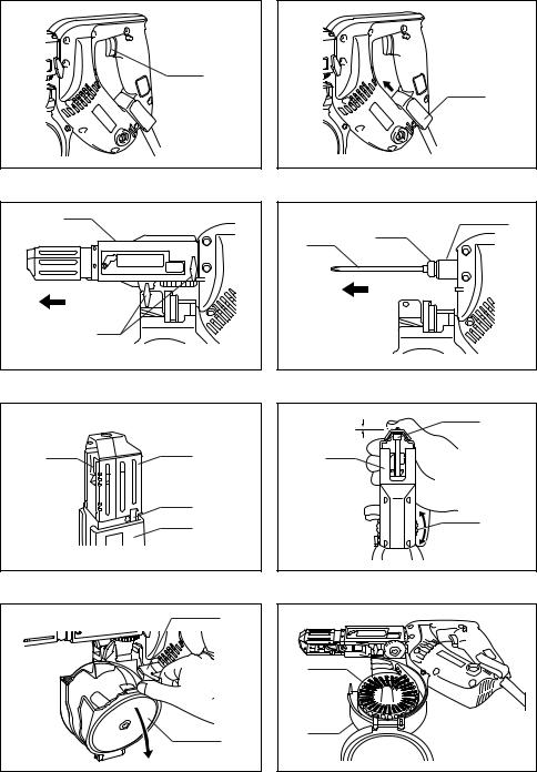
Switch action (Fig. 1)
CAUTION:
•Before plugging in the tool, always check to see that the switch trigger actuates properly and returns to the “OFF” position when released.
To start the tool, simply pull the trigger. Release the trigger to stop.
For continuous operation, pull the trigger and then push in the lock button.
To stop the tool from the locked position, pull the switch trigger fully, then release it.
Hook (Fig. 2)
The hook is convenient for hooking the tool to your belt. It can be installed on either side of the tool. To remove it, pull it out in the direction of the arrow while raising. To install the hook, push it down until it “clicks” into place on the tool.
ASSEMBLY
CAUTION:
•Always be sure that the tool is switched off and unplugged before carrying out any work on the tool.
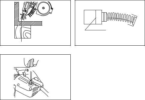
Installing or removing bit
Loosen the thumb screws which secure the casing. Pull out the casing in the direction of the arrow. (Fig. 3) Press the dust cover toward the plain bearing and pull
2.Always be sure you have a firm footing. Be sure out the bit. If the dust cover cannot be moved as far as
no one is below when using the tool in high locations.
3.Hold the tool firmly.
4.Keep hands away from rotating parts.
5.Do not touch the bit or the workpiece immediately after operation; they may be extremely hot and could burn your skin.
SAVE THESE INSTRUCTIONS.
the plain bearing, try it again after turning the bit slightly. To install the bit, insert it into the socket while turning it slightly. After installing, always make sure that the bit is securely held in place by trying to pull it out. (Fig. 4)
6
 Loading...