


6821
Makita 6821 Instruction Manual
GB
Drywall Screwdriver Instruction Manual
F
Visseuse Manuel d’instructions
D
Schrauber Betriebsanleitung
I
Avvitatrice per Muri a Secco Istruzioni per l’uso
NL
“Drywall” schroevendraaier Gebruiksaanwijzing
E
Atornillador “Drywall” Manual de instrucciones
P
Aparafusadora Manual de instruções
DK
Elektronisk Skruemaskine Brugsanvisning
S
Gipsskruvdragare Bruksanvisning
N
Skrutrekker til Gipsskruer Bruksanvisning
SF
Kiviseinäruuvinväännin Käyttöohje
GR Κατσαβίδι Ξηρού Τοίχου Οδηγίες χρήσεως
6821
1
1
2
3
4
2
12
1
2
34
5
6
56
7
8
9
78
2

ENGLISH
Explanation of general view
1 Locator
2 Locking sleeve
3Bit
4 Magnetic bit holder
5 Switch trigger
6 Lock button
SPECIFICATIONS
Model 6821
Capacities
Self drilling screw ................................................ 6mm
Drywall screw ..................................................... 5 mm
Bit shank size .................................... ..... ..... ...... . 1 /4” Hex
No load speed (min
Overall length .................................................... 273 mm
Net weight ......................... ..... ...... ...........................1.3 kg
• Due to our continuin g program of research and devel-
opment, the specifications herein are subject to change
without notice.
• Note: Specifications may differ from country to country.
Power sup ply
The tool should be connected only to a power supply of
the same voltage as indicated on the nameplate, and can
only be operated on sing le-phase AC supply. They are
double-insulated in accor dance with E uropean Standa rd
and can, therefore, also be use d from sockets without
earth wire.
Safety hints
For your own safety, plea se refer to the enclosed safety
instructions.
-1
) ....................... ..... ..... ...... .0 –4,000
SPECIFIC SAFET Y RULES
DO NOT let comfort or familiarity with product
GEB017-1
(gained from repeated use) replace strict
adherence to screwdriver safety rules. If you use
this tool unsafely or incorrectly, you can suffer
serious personal injury.
1. Hold power tools by insulated gripping surfaces
when performing an operation where the cutting
tool may contact hidden wiring or its own cord.
Contact with a “live” wire will make exposed metal
parts of the tool “live” and shock the operator.
2. Always be sure you have a firm foot ing. Be s ure
no one is belo w wh en usi ng t he tool i n h igh l o ca tions.
3. Hold the tool firmly.
4. Keep hands away from rotating parts.
5. Do not tou ch the bit or the workpiece imme di-
ately after operatio n; they may be extremely hot
and could burn your skin.
SAVE THESE INSTRUCTIONS.
WARNING:
MISUSE or failure to follo w the s afety r ules stated
in this instruction manual may cause serious
personal injury.
7 Reversing switch lever
8 Clockwise rotation
9 Counterclockwise rotation
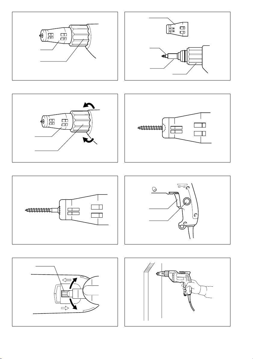
OPERATING INSTRUCTIONS
Removing or installing the bit (Fig. 1 & 2)
Important:
Always be sure that the tool is switched off and
unplugged before removing or installing the bit.
Pull the locator out of the locking sleeve while turning the
locator slightly. Then grasp the bit with a pair of pliers and
pull the bit out of the magnetic bit holder. Sometimes, it
helps to wiggle the bit with the plires as you pull.
To install the b it, push th e bit fir mly into the magnet ic bit
holder. Then install the locator by pushing it firmly onto
the locking sleeve while turning the locator slightly.
Depth adjustment (Fig. 3, 4 & 5)
Adjust the locator by turnin g the locking sleeve. One full
turn of the locking sleeve moves the locator 2 mm.
Initially, adjust the locator so tha t the tip of the locator is
flush with the base of the screw head . Dr i ve a tr ial screw
into your material or a piece of duplicate material. If the
depth is not suitable for the screw, continue adjusting
until the proper depth setting is obtained.
Switch action (Fig. 6)
CAUTION:
Before plugging in the too l, always check to see that the
switch trigger actuates pro per ly and ret ur ns to the “ OFF”
position when released.
To star t the tool, simply pull the tr igger. Tool speed is
increased by increasing p ress ure on the trigger. Release
the trigger to stop.
For continuous operation, pull the trigger and then push
in the lock button. To stop the tool from the locked position, pull the trigger fully, then release it.
Reversing switch action (Fig. 7)
This tool has a reversing switch to change the direction of
rotation. Move the reversing switch lever to the “
position for clockwise rotati on or the “
counterclockwise rotation.
CAUTION:
• Always check the direction of rotation before opration.
• Use the reversing switch only after the tool comes to a
complete stop. Charging the direction of rotation before
the tool stops may damage the tool.
E” position for
D”
3

Operation (Fig. 8)
Fit the screw on the point of the bit and place the point of
the screw on the surface of the workpiece to be fastened.
Apply presssure to the tool and star t it. Withdraw the tool
as soon as the clutch cuts in. Then release the trigger.
CAUTION:
• When fitting the screw onto the point of the bit, be careful not to push in on the screw. If the screw is pushed
in, the clutch will engage and the screw will rotate suddenly. This could damage a workpeice or cause an
injury.
• Make sure that the bit is inserted straight in the screw
head, or the screw and/or bit may be damaged.
• Do not continue unnecessary clutching operation.
MAINTENANCE
CAUTION:
Always be sure that the tool is switched off and
unplugged before carrying out any work on the tool.
To maintain product safety and reliability, repairs, maintenance or adjustment should be carried out by a Makita
Authorized Service Center.
4

FRANÇAIS
1 Positionneur
2 Manchon de verrouillage
3 Embout
4 Porte-embout magnétique
Descriptif
5 Gâchette
6 Bouton de blocage
7 Inverseur
8 Rotation vers la droite
9 Rotation vers la gauche
SPECIFICATIONS
Modèle 6821
Capacités
Vis auto-foreuses .................................................6 mm
Vis pour plaque de plâtre .....................................5 mm
Dimension de l’emmanchement ......................... 1/4” hex
Vitesse à vide (min
Longueur hors tout .............................................273 mm
Pois net .................................................................. 1,3 kg
• Etant donné l’évolutio n constante de notre programme
de recherche et de dé veloppement, les spécifications
contenues dans ce manuel sont sujette s à mo di fica tion
sans préavis.
• Note : Les spécifications peuvent varier suivant les
pays.
Alimentation
L’outil ne devra être raccor dé qu ’à u ne alimentation de la
même tension que cel le qui figur e sur la plaque signalétique, et il ne pourra fonctionner que sur un cou rant secteur monophasé. Réal isé avec une double isola tion, il est
conforme à la réglemen tation euro péenne et pe ut de ce
fait être alimenté sans mise à la terre.
Consignes de sécurité
Pour votre propre sécurité, repor tez-vous aux co nsignes
de sécurité qui accompagnent l’outil.
-1
) ....................................... 0 – 4 000
PRECAUTIONS SUPPLEMENTAIRES POUR
L’OUTIL
NE vous laissez PAS tromper (au fil d’une
utilisation répétée) par un sentiment d’aisance et
de familiarité avec l’outil, en négligeant le respect
rigoureux des consignes de sécurité qui
accompagnent la v isseuse.
1. Saisissez les outils électriques par leurs sur-
faces de poigne isolées lorsque vous effectuez
une opération au cou rs de laquelle l’outil tranchant peut entrer en contact avec des fils cachés
ou avec son propre cordon d’alim entation.
Le contact avec un fil sous tension mettra les parties
métalliques exposées de l’outil sous tension, causant ainsi un choc électrique chez l’utilisateur.
2. Veillez à toujours avoir un bon équilibre . Vérifiez
qu’il n’y a per s on ne dess ou s q ua nd v o us ut i l ise z
l’outil en hauteur.
3. Tenez l’outil fermement.
4. N’approchez pas les mains des pièces en mou-
vement.
5. Ne touchez ni la vis ni son support immédiate-
ment après un vissage. Ils peuvent être extrêmement chauds et risquer de vous brûler.
CONSERVEZ CES INSTRUCTIONS.
AVERTISSEMENT :
LA MAUVAISE UTILISATION de l’outil ou
l’ignorance des consignes de sécurité du présent
manuel d’instructions peuvent entraîner une
grave blessure.
MODE D’EMPLOI
Pose et dépose de l’embout (Fig. 1 et 2)
Important :
Assurez-vous toujours que le conta ct est coupé et l’outi l
débranché avant de retirer ou d’installer l’embout.
Sortez le positi onneur du manchon de verrouillage tout
en tournant légèrement le positionneur. Puis, saisissez
l’embout à l’aide de pi nces, et sor tez l’embout du por teembout magnétique. Pour faciliter l’opération, agitez
l’embout avec les pinces pendant que vous tirez dessus.
Pour installer l’embout, en foncez-le à fond dans le por teembout magnétique. Puis, remontez le positionneur en le
poussant à fond contre le manchon de verrouillage tout
en tournant légèrement le positionneur.
Réglage de profondeur (Fig. 3, 4 et 5)
Réglez le positionn eur en tournant le man chon de verrouillage. Un tour complet du manchon de verrouillage
déplace le positionneur de 2 mm.
Au début, réglez le positionneur de façon que son
extrémité arrive au niveau de la base de la tête de vis.
Enfoncez une vis d’essai dans votre matériau ou dans un
morceau de matériau équivalent. Si la profondeur ne
convient pas pour la vis, con tinuez le ré glage jusqu ’à ce
que vous obteniez la profondeur voulue.
Utilisation de la gâchette (Fig. 6)
ATTENTION :
Avant de brancher l’outil sur le secteur, vérifiez toujours
que la gâchette fonctionne correctement et qu’elle revient
sur la position “OFF” quand vous la relâchez.
Pour mettre l’outil en route, tirez simplement sur la
gâchette. La vitesse augment e avec la pression exercée
sur la gâchette. Pour arrêter l’outil, relâchez la gâchette.
Pour une utilisation continue, tirez sur la gâchette et
appuyez sur le bouton de blocage. Pour arrêter l’outil
pendant une utilisation continue, tirez à fond sur la
gâchette puis relâchez-la.
5

Inverseur (Fig. 7)
L’outil est muni d’un inverseur qui per met de changer l e
sens de rotation. Déplacez l’inverseur sur la position
“
D” pour obtenir u ne rotation vers la droite, et sur la
E” pour obtenir une rotation vers la gauche.
position “
ATTENTION :
• Vérifiez toujours le sens de rotation avant de mettre
l’outil en marche.
• N’actionnez l’inverseur qu’une fois que l’outil est complètement arrêté. Si vous changez l e sens de rotation
avant l’arrêt de l’outil, vous risquez de l’endommager.
Pour visser (Fig. 8)
Placez la vis à l’extrémité de l’embout et appliquez la
pointe de la vis contre la surface de la pièce à visser.
Exercez une pression sur l’outil et appuyez sur la
gachette. Retirez l’outil dès que la vis est complè tement
enfoncée. Puis, relâchez la gâchette.
ATTENTION :
• Quand vous fixez la vis sur la pointe de l’embout, faites
attention de ne p as enfoncer la vi s. Si la v is s’en fonce,
l’embrayage s’engagera et la vis se mettra br usquement à tourn er, ce qui pourrait endommager la pièce
ou provoquer des blessures.
• Vérifiez que l’embout est inséré droit sur la tête de vis,
sinon la vis et/ou l’embout pourraient être endommagés.
• Ne prolongez pas l’embrayage plus qu’il n’est nécessaire.
ENTRETIEN
ATTENTION :
Avant toute intervention, assurez -vous que le co nta ct est
coupé et l’outil débranché.
Pour maintenir la sécurité et la fiabilité du produit, le s
réparations, l’entretien ou les réglages doivent être effectués par le Centre d’Entretien Makita.
6

DEUTSCH
Übersicht
1 Führungshülse
2 Feststellhülse
3 Schraubendrehereinsatz
4 Magnetischer Bit-Halter
5 Elektronikschalter
6 Schalterarretierung
TECHNISCHE DATEN
Modell 6821
Maße
Selbstbohrschrauben ..... ................ ................ ..... 6mm
Schnellbauschrauben .... ..................................... 5 mm
Werkzeugaufnahme ..........................1/4-Zoll-Sechskant
Leerlaufdrehzah l (mi n
Gesamtlänge ............... ...................................... 273m m
Nettogewicht .......................... ................................ .1,3 kg
• Wir behalten uns vor, Änderungen im Zuge der Ent-
wicklung und des technischen Fortsch ritts ohne vorhe-
rige Ankündigung vorzunehmen.
• Hinweis: Die technische n Daten können von Land zu
Land abweichen.
Netzanschluß
Die Maschine darf nur an die auf dem Typenschild
angegebene Netzspa nnung angeschlossen wer den und
arbeitet nur mit Einphasen- Wechselspannung. Sie ist
entsprechend den Europäischen Richtlinien doppelt
schutzisolier t und kann daher auch an Steckdosen ohne
Erdanschluß betrieben werden.
Sicherheitshinweise
Lesen und beachten Sie diese Hinweise, bevor Sie das
Gerät benutzen.
-1
) ........................ ............ 0–4000
ZUSÄTZLICHE
SICHERHEITZSBESTIMMUNGEN
Lassen Sie sich NICHT durch Bequemlichkeit
oder Vertrautheit mit dem Produkt (durch
wiederholten Gebrauch erworben) von der
strikten Einhaltung der SchrauberSicherheitsregeln ab halten.
1. Halten Sie Elek trowerkzeuge nur an d en isolier-
ten Griffflächen, wenn Sie Arbeiten ausführen,
bei denen die Gefahr besteht, dass verborgene
Kabel oder das eigene Kabel kontaktiert werden.
Bei Kontakt mit einem stromfüh renden Kabel werden die freiliegenden Metallteile des Werkzeugs
ebenfalls stromführend, so das s der Benutzer ei nen
elektrischen Schlag erleiden kann.
2. Sorgen Sie für sicheren Stand und halten Sie
jederzeit Gleichgewicht. S tellen Sie sicher, daß
sich bei Einsatz der Maschine an hochgelegenen
Arbeitsplätzen keine Personen da runter aufhalten.
3. Halten Sie die Maschine sicher fest.
4. Halten Sie die Hä nde vo n roti erende n T eile n fern.
5. Das Einsatzwerkzeug oder das bearbeitete
Werkstück nicht unmittelbar nach Beendigung
der Arbeit berühren. Sie können sehr heiß sein
und Verbrennungen verursachen.
BEWAHREN SIE DIESE HINWEISE
SORGFÄLTIG AUF.
7 Drehrichtungsumschalter
8 Rechtslauf
9 Linkslauf
WARNUNG:
MISSBRAUCH oder Missachtung der
Sicherheitsvorschriften in dieser Anleitung
können schwere Verletzungen verursachen.
BEDIENUNGSHINWEISE
Montage bzw. Demontage von
Schraubendrehereinsätzen (Abb. 1 u. 2)
Wichtig:
Vergewissern Sie sich vor der Montage bz w. Demontage
von Schraubendrehereinsätzen, daß die Maschine abgeschaltet und der Netzstecker gezogen ist.
Zur Demontage die Führungshülse aus der Feststellhülse ziehen, während die Führungshülse geringfügig
gedreht wird. Dann den Schraubendrehereinsatz mit
einer Spitzzange aus dem mag netischen Bit-Halter ziehen. Sitzt der Schraubendrehereinsatz fest, bewegen Sie
ihn mit der Zange seitlich hin und her.
Zur Montage den Schraubendrehereinsatz fest in den
magnetischen Bit-Halter stecken. Dann die Führungshülse fest in die Feststellhülse stecken, während die Führungshülse geringfügig gedreht wird.
Tiefenbegrenzung (Abb. 3, 4 u. 5)
Die Führungshülse durch Drehen der Feststellhülse in
die gewünschte Position bringen. Die Schraubtiefe
ändert sich pro Umdrehung der Feststellhülse um
2,0 mm.
Zur Grundeins t ell u n g so l lt e d ie S p it ze de r Fü hrun g shü l s e
bündig mit dem Schraubenkopf sein. Führen Sie
zunächst eine Probeverschraubung durch. Falls diese
Tiefeneinstellung für die Schraube nicht geeignet ist,
nehmen Sie die erforderliche Änderung vor.
Schalterfunktion (Abb. 6)
VORSICHT:
Vor dem Anschließen der Maschine an das Str omnetz
stets überprüfen, ob de r Elektronikschalter ordnu ngsgemäß funktio niert und beim Loslasse n i n di e AUS-Stellun g
zurückkehrt.
Zum Einschalten drücken Sie den Elektronikschalter.
Zum Ausschalten lassen Si e de n Sch alter lo s. Die Dre hzahl erhöht sich durch verstärkte Druckausübung auf den
Elektronikschalter. Zum Ausschalten den Schalter loslassen.
Für Dauerbetrieb drücken Sie den Elektronikschalter und
gleichzeitig die Schalterarretierung. Zum Ausschalten
des Dauerbetriebs den Elektronikschalter drücken und
wieder loslassen.
7

Drehrichtungsumschalter (Abb. 7)
Mit dem Drehrich tun gsu msch al te r kann d ie Drehrichtung
verändert werden. Sc halten Sie für Re chts lauf auf “
für Linkslauf auf “
VORSICHT:
• Prüfen Sie stets die Dr ehrichtung, bevor Sie mit dem
Schraubvorgang beginnen.
• Wechseln Sie niemals die Drehrichtung, bevor der
Motor zum Stillstand gekommen ist. Andernfalls kann
die Maschine beschädigt werden.
E”.
D”,
Betrieb (Abb. 8)
Die Schraube in de n S chrau ben drehereinsatz eins et zen.
Mit Druck auf die Maschine die Verschraubung durchführen. Den Schraubvorgang beenden, sobald di e Kupplung
einrastet. Dann den Elektronikschalter loslassen.
VORSICHT:
• Beim Einpassen der Schraube in die Spitze des
Schraubendreherei ns atzes da rauf achten, nicht auf die
Schraube zu drücken. Anderenfalls wi rd die Kupplung
eingerückt, und die Schraube beginnt plötzlich zu rotieren. Dies kann zu Verletzungen ode r einer Beschädigung des Werkstücks führen.
• Sicherstellen , da ß der Schraubendreh ere i nsa tz ge rade
in den Schraubenkopf eingeführt wird, da Schraube
und/oder Schraubendrehereinsatz anderenfalls
beschädigt werden können.
• Keine unnötigen Einkupplungsvorgänge ausführen.
WARTUNG
VORSICHT:
Vor Arbeiten an der Maschine vergewissern Sie sich, daß
sich der Schalter i n der ,,O FF-Position” befind et und der
Netzstecker gezogen ist.
Um die Sicherheit und Zuverlässigkeit dieses Gerätes zu
gewährleisten, sollten Reparatur-, Wartungs-, und Einstellarbeiten nur von durch Makita autorisierten Werkstätter oder Kundendienstze ntren unter ausschließ licher
Verwendung von Makita-Originalersatzteilen ausgeführ t
werden.
8

ITALIANO
1 Localizzatore
2 Manicotto di bloccaggio
3Punta
4 Supporto magnetico punta
Visione generale
5 Grilletto interruttore
6 Bottone di bloccaggio
7 Leva interruttore di inversione
8 Rotazione in senso orario
9 Rotazione in senso antiorario
DATI TECNICI
Modello 6821
Capacità
Vite autoperforante ............................................. . 6 mm
Vite per muri a secco ...........................................5 mm
Dimensioni codolo punta ......................... 1/4” esagonale
Velocità a vuoto (min
Lunghezza totale ................................................273 mm
Peso netto .............................................................. 1,3 kg
• Per il nostro programma di ricerca e sviluppo continui, i
dati tecnici sono soggetti a modifiche senza preavviso.
• Nota: I dati tecnici potrebb ero differire a seconda del
paese di destinazione del modello.
Alimentazione
L’utensile deve essere collegato ad una presa di corrente
con la stessa tensione indicata sulla targhetta del nome,
e può funzionare soltanto con la corrente alternata
monofase. Esso ha un doppio isolamento i n osservanza
alle norme europee, per cui può essere usato con le
prese di corrente sprovviste della messa a terra.
Consigli per la sicurezza
Per la vostra sicurezza, riferitevi alle accluse istruzioni
per la sicurezza.
-1
) ....................................0 – 4.000
UL TERIORI REGOLE DI SICUREZZA PER
L’U TEN SILE
NON lasciar e che l a com odità o la f amili arit à con
il prodotto (acquisita con l’uso ripetuto)
sostituisca la stretta osservanza delle norme di
sicurezza per l’avvitatore.
1. Tenere gli utensili elettrici per le superfici di
presa isolate quando si eseguono operazioni
durante le quali l’utensile di taglio potrebbe
venire a co ntatto con fili elet trici n ascosti o co n
il suo stesso cavo di alimentazione.
Il contatto con un filo “sotto t ensione” mette “sotto
tensione” le parti metalliche esposte dell’utensile
causando una scossa all'operatore.
2. Appoggiar e sempre saldamente i piedi a terra.
Accertarsi che non ci sia nessuno sotto quando
si lavora su un posto alto.
3. Tenere saldamente l’uten sile.
4. Tenere le mani lontane dalle parti rotanti.
5. Non toccare la punta o ppure il pezzo sotto lavo-
razione subito dopo la foratura, potrebbero
essere estremamente caldi e causare ustioni alla
pelle.
CONSERVA TE QUESTE ISTRUZIONI.
ATTENZIONE:
L’utilizzo SBAGLIATO o la mancata osservanza
delle norme di sicurezza di questo manuale di
istruzioni potrebbero causare serie lesioni
personali.
ISTRUZIONI PER L’USO
Rimozione o installazione della punta (Fig. 1 e 2)
Importante:
Accertarsi sempre che l’utensile sia spento e staccato
dalla presa di corrente prima di r imuovere o di installare
la punta.
Tirare il localizzatore fuori dal manicotto di bloccaggio
girandolo leggermente. Afferrare poi la punta con una
pinza e tirarla fuor i dal supporto magnetico. A volte si
può facilitare la rimozione dimenando la punta con la
pinza quando la si tira via.
Per installare la punta, spingerla saldamente nel supporto magne tico. Installare poi il localizzato re spingendolo saldamente nel manicotto di bloccaggio girandolo
leggermente.
Regolazione della profondità (Fig. 3, 4 e 5)
Regolare il localizzatore girando il manicotto di bloccaggio. Un giro completo de l manicotto sposta il localizzatore di 2 mm.
Regolare prima il localizzatore in modo che la sua punta
sia a livello con la base della testa della vite. Avvitare una
vite di prova nel materiale o in un pezzo di duplica to del
materiale. Se la profondità non è adatta alla vite, continuare a regolare finché non si ottiene la profondità adatta.
Azionamento dell’interruttore (Fig. 6)
ATTENZIONE:
Prima di collegare l’utensi le all a pre sa di c orr en te, accertarsi sempre che il grilletto dell’interruttore funzioni correttamente e che ritorni sulla posizione “OFF” quando
viene rilasciato.
Per avviare l’utensile, schiacciare semplicemente il gr illetto. La velocità dell’utensile si aumen ta aumentando la
pressione sul grilletto. Rilasciare il grilletto per fermarlo.
Per il funzionamento continuo, schiacciare il grilletto e
spingere poi il botto ne di bloccaggio. Per fermare l’utensile dalla posizione di bloccagg io, schiacciare completamente il grilletto e rilasciarlo.
9

Azionamento dell’interruttore di inversione
(Fig. 7)
Questo utensile è dotato di un i nterruttore di inversione
per cambiare la di rezione di rotazion e. Spostare la leva
dell’interruttore di inversione sulla posizione “
rotazione in senso orario, oppure sulla posizione “
per la rotazione in senso antiorario.
ATTENZIONE:
• Controllare semp re la direzione d i rotazione pr ima del
funzionamento.
• Usare l’interruttore di inversione soltanto dopo che
l’utensile si è fermato completamente. Il cambiamento
di direzione della rotazione prima dell’arresto completo
potrebbe danneggiare l’utensile.
Funzionamento (Fig. 8)
Mettere la vite sulla punta e mettere la punta de lla vite
sulla superficie del pezzo da lavorare da fissare. Esercitare una pressione sull’utensile e avviarlo. Ritirare l’utensile non appena la frizione si innesta. Rilasciare poi il
grilletto.
ATTENZIONE:
• Quando si mette la vite sull’estremità d ella punta, fare
attenzione a non spin gerla d entro. Se si spinge dentro
la vite, la frizione si innesta e la vite comincia improvvisamente a girar e. Ciò potrebbe dannegg iare il p ezzo
da lavorare o causare ferite.
• Accertar si che la punta sia inserita diritta nella testa
della vite, perché altr imenti la vite e/o la punta p otrebbero danneggiarsi.
• Non continuare a far funzionare inutilmente la frizione.
D” per la
E”
MANUTENZIONE
ATTENZIONE:
Prima di eseguire qualsiasi lavoro sull’utensile, accertatevi sempre che sia spenta e staccata d alla presa di corrente.
Per mantenere la sicurezza e l’affidabilità del prodotto, le
riparazioni, la m anutenz ione o le regola zioni dovre bbero
essere eseguite da un centro di assiste nza Makit a aut orizzato.
10
 Loading...