

Page 1

Spindle-Table Crash
Avoidance Function
Operation Manual
Professional 6
0847C-1610 (en)
Original instructions
MAKINO GmbH
Essener Bogen 5, 22419 Hamburg
Phone ++49 / 40 / 29 80 90
Fax ++49 / 40 / 29 80 94 00
Page 2

Page 3

Imprint I
Imprint
Editor: MAKINO GmbH
Essener Bogen 5
D-22419 Hamburg
Germany
Tel.: ++49 / 40 / 298 09 - 0
Fax: ++49 / 40 / 298 09 - 400
e-mail: documentation@makino.de
Date issued: 2016-10
MAKINO 0847C-1610 (en)
Page 4

II Imprint
0847C-1610 (en) MAKINO
Page 5

Revisions III
Revisions
Date Chapter/Page Modification
MAKINO 0847C-1610 (en)
Page 6

IV Revisions
Revisions
Date Chapter/Page Modification
0847C-1610 (en) MAKINO
Page 7

Table of contents V
Table of contents
0 GENERAL SAFETY INSTRUCTIONS ....................................................................................................... 0-1
0.1 Indicator words and their meaning .......................................................................................................... 0-1
1INTRODUCTION ............................................................................................................................................. 1-1
2OUTLINE ............................................................................................................................................................. 2-1
3 OPERATIONAL NOTES ................................................................................................................................ 3-1
4 SWITCHING ON/OFF THE 3D CRASH AVOIDANCE MODE ...................................................... 4-1
4.1 M Codes .............................................................................................................................................................. 4-1
4.2 Function Button ................................................................................................................................................ 4-1
4.3 Verification of 3D Crash Avoidance State .............................................................................................. 4-2
5 CRASH CHECK ALARM AND RECOVERY ........................................................................................... 5-1
6 USE OF TOOL SHAPE DATA TRANSFER FUNCTION .................................................................... 6-1
6.1 Timing of Tool Shape Data Transfer Function ...................................................................................... 6-1
6.2 Tool Length, Tool Radius Data Handled by Tool Shape Data Transfer Function ................... 6-2
6.3 Tool Length (Check), Tool Radius/Diameter (Check) of Tool Shape
Data Transfer Function .................................................................................................................................. 6-2
6.4 Use of Tool Shape Data Transfer Function in dummy pot .............................................................. 6-3
7 Z AXIS COLLISION AVOIDANCE FUNCTION .................................................................................... 7-1
7.1 Z Axis Collision Avoidance Function Setting ......................................................................................... 7-3
7.2 Reference Position Z Setting according to M Code ........................................................................... 7-4
7.3 Cancel of the Limitation Area of Z Axis Collision Avoidance Function ....................................... 7-5
7.4 Application Example of Limitation Area of Z Axis Collision Avoidance Function ................... 7-5
7.5 Motion of the Limitation Area of Z Axis Collision Avoidance Function for Workpiece Rotation
Type Machines with 4 or 5 Axes ................................................................................................................ 7-7
7.6 Verification of Z Axis Collision Avoidance Function ........................................................................... 7-8
8 OTHER FUNCTIONS DIFFERENT IN EACH MACHINE TYPE ...................................................... 8-1
8.1 Use of 3DC Y position setting function (ONLY MCC2013VG) ........................................................ 8-1
8.2 About Automatic Pallet Change (APC) of a/A series-5XR machines ........................................... 8-2
8.3 About Spindle Model Change in EG3010 .............................................................................................. 8-3
8.4 About high-speed attachment specification in iQ300 ...................................................................... 8-4
9 MACHINE PARAMETERS ........................................................................................................................... 9-1
10 MACHINE ALARMS ................................................................................................................................... 10-1
MAKINO 0847C-1610 (en)
Page 8

VI Table of contents
0847C-1610 (en) MAKINO
Page 9
GENERAL SAFETY INSTRUCTIONS 0-1
0 GENERAL SAFETY INSTRUCTIONS
The hazards involved in operating the machine are identified by the following means:
- In this manual, warning notices serve to indicate aspects which are relevant to safety.
- On the machine, warning signs point out aspects which are relevant to safety.
0.1 Indicator words and their meaning
The indicator words use for warning notices are divided into the categories listed below, according to the
accepted degree of risk involved.
Consciously ignoring these warning notices can result in accidents, serious injuries or death.
Furthermore, serious damage may be caused to the machine and its auxiliary units. The warning notices
below must there be followed without fail!
DANGER!
Indicator word used to denote an immediately hazardous situation which, if not avoided,
will result in serious injury or death.
WARNING!
Indicator word used to denote a potentially hazardous situation which, if not avoided,
could result in serious injury or death.
CAUTION!
Indicator word used to denote a potentially hazardous situation which, if not avoided,
could result in slight to moderate injuries.
NOTICE! Indicator word used to denote a potentially hazardous situation which, if not avoided,
could result in damage to property.
REMARK Indicator word used to point out important or useful information.
MAKINO 0847C-1610 (en)
Page 10

0-2 GENERAL SAFETY INSTRUCTIONS
0847C-1610 (en) MAKINO
Page 11

INTRODUCTION 1-1
1INTRODUCTION
REMARK 1. Read this manual carefully before operating the machine.
2. Store this manual in a clearly marked location for easy reference.
3. All rights reserved. No part of this document may be reproduced, copied, or modified
in any form or any means without direct permission of Makino Milling Machine Co., Ltd.
The present document contains customer specific technical information concerning the “Spindle – Table
Crash Avoidance Function” (hereafter it is referred to as “3D crash avoidance function”).
This technical information describes the following:
- Function explanation
- Operational notes
- Switching ON/OFF the 3D crash avoidance mode
- Use of Tool Shape Data Transfer Function
- Use of the Z Axis Collision Avoidance Function
- Other functions different in each machine type
MAKINO 0847C-1610 (en)
Page 12

1-2 INTRODUCTION
0847C-1610 (en) MAKINO
Page 13
OUTLINE 2-1
2OUTLINE
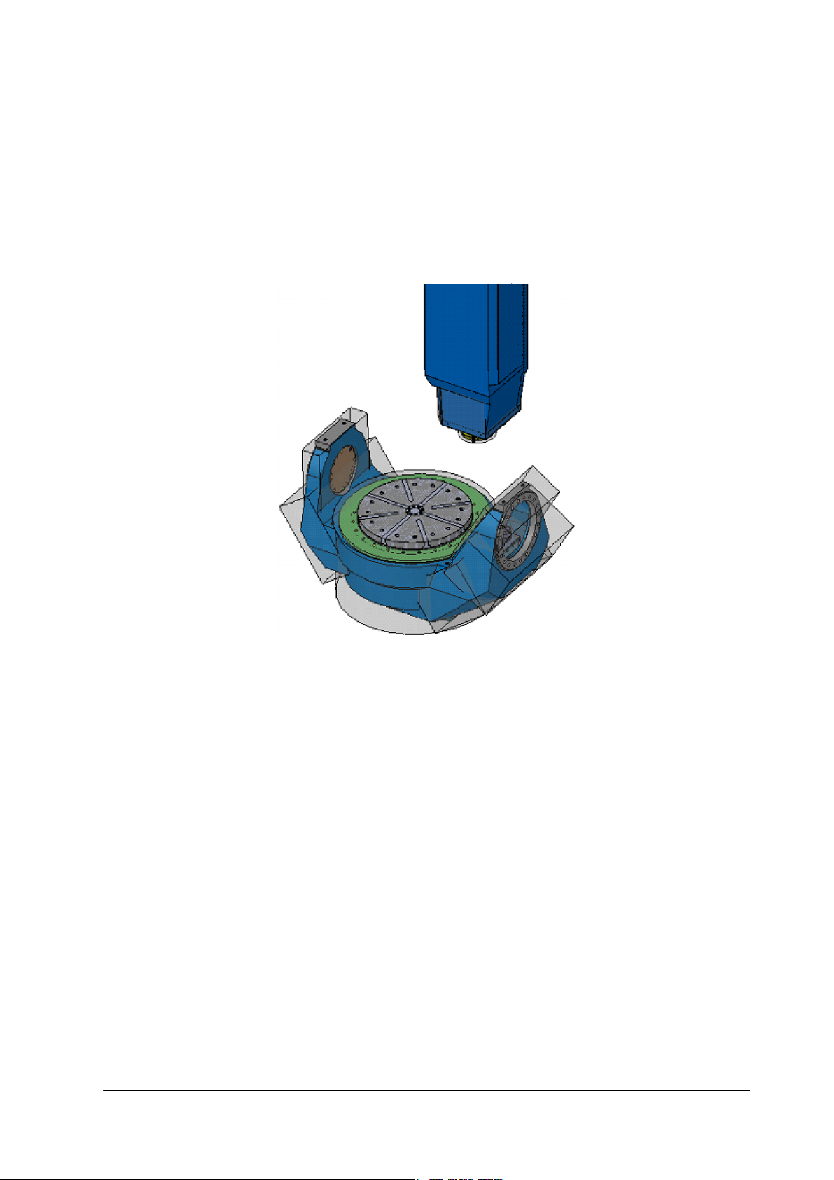
3D crash avoidance function allows stopping the machine in advance by an Crash Check Alarm when a
possible collision is detected between spindle and table which are defined by simplified factory preset geometrical configurations as shown in “Fig. 2-1: ”.
Usually this function becomes active at the machine start-up. No special handling by an operator is required.
Fig. 2-1:
Moreover, it is possible to prevent the following accidents using the Tool Shape Data Transfer Function
(chapter “6 USE OF TOOL SHAPE DATA TRANSFER FUNCTION”) and the Z Axis Collision Avoidance Function (chapter “7 Z AXIS COLLISION AVOIDANCE FUNCTION”).
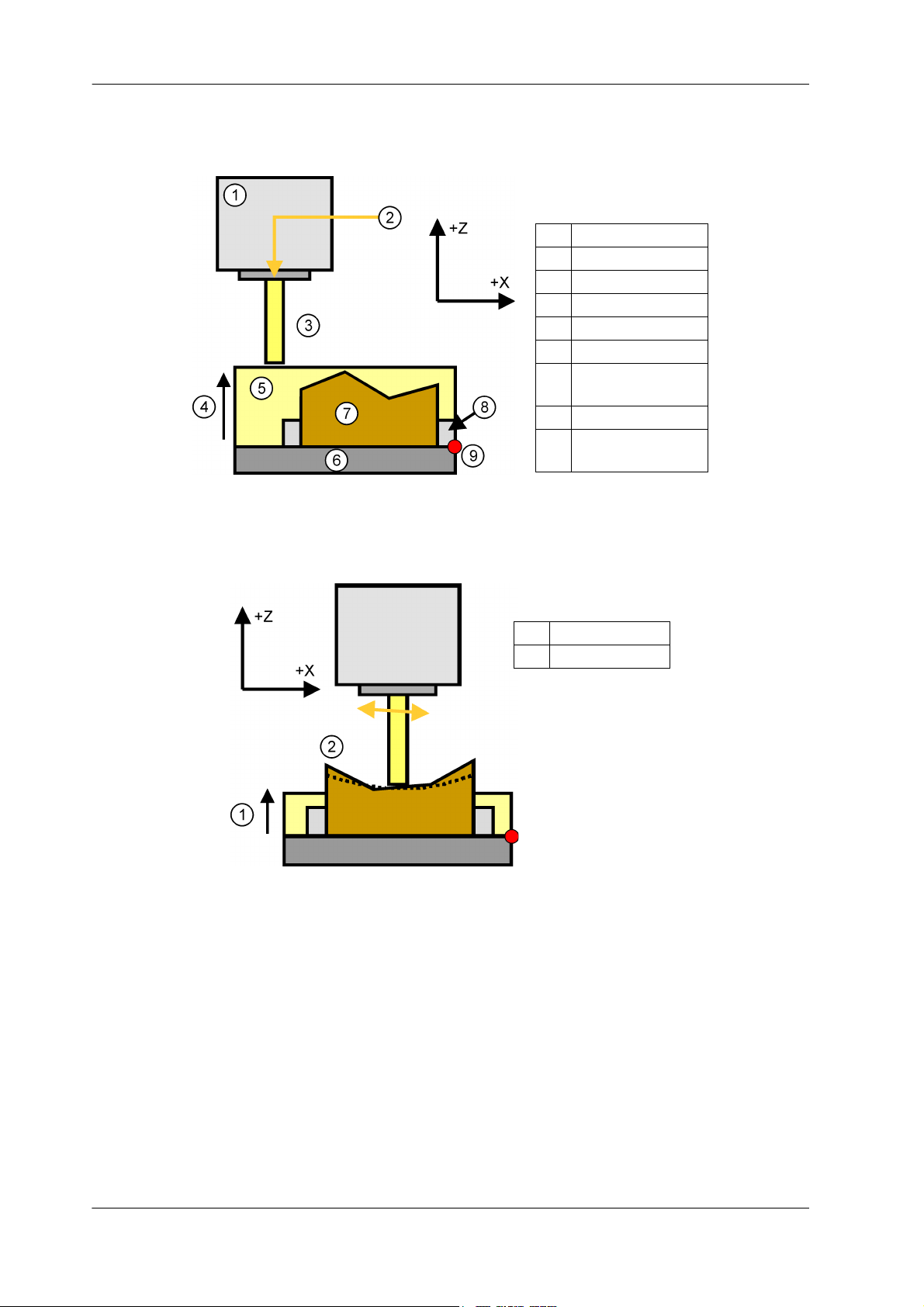
- Collision during the initial approach in Z axis direction (“Fig. 2-2: Initial approach”)
- Collision during the movement in –Z axis direction outwards machining area (“Fig. 2-3: Machining”)
MAKINO 0847C-1610 (en)
Page 14
2-2 OUTLINE
Legend
[1] Spindle
[2] Approach
[3] Tool model
[4] M code
[5] Limitation area
[6] Table
[7] Workpiece before
cutting
[8] Fixture
[9] Reference position
Z
Legend
[1] M code
[2] Machining area
Fig. 2-2: Initial approach
Fig. 2-3: Machining
0847C-1610 (en) MAKINO
Page 15
OPERATIONAL NOTES 3-1
3 OPERATIONAL NOTES
CAUTION!
Check that 3D crash avoidance function is active before starting machine operation.
Particularly, note that this function will not be active if referencing of all coordinate axes
had not been executed at least once.
NOTICE! 3D crash avoidance function may temporarily turn off during Machine Lock or while
searching for the program restart.
NOTICE! Please move axes in the opposite direction and push [NC Reset] button, when Crash
Check Alarm has been generated by this function. Movement in the direction of further
collision with [OT Release] button pushed is impossible. In order to enable movement in
the direction of further collision, first do NC reset and then turn this function OFF.
NOTICE! Except the automatic non-contact tool measuring device (separate-type) of D500, this
function is temporarily turned off and then restores during the automatic tool measurement procedure.
However, this function may remain turned off if there has been some intervention or some
alarms have been generated in the course of the measurement procedure.
Please be sure to have confirmed the status of the 3D crash avoidance mode as shown in
paragraph “4.3 Verification of 3D Crash Avoidance State” before proceeding to the next
operation execution.
NOTICE! The spindle model of the machine with the bar spindle is set with W axis at a reference
position. When the bar spindle is extended, Shape model of 3D crash avoidance func-
tion does not apply to the extension of the bar spindle.
CAUTION!
3D crash avoidance function does not apply to workpieces, jigs, tool holders, angle
plates etc.
Also note that 3D crash avoidance function does not apply to structural elements being
not in their usual positions during machining, such as advanced ATC arm or covers of auxiliary appliances in opened state etc.
Using Tool Shape Data Transfer function, tool’s cylindrical model is created so that tool
also becomes an object for 3D crash avoidance.
CAUTION!
As a general rule, 3D crash avoidance function does not apply to the chuck of WPS specifications, CPH arm, and tale stock which can be attached, removed and shifted to other
position.
And also, flexible nozzles do not apply.
CAUTION!
3D crash avoidance function does not apply to the Programmable coolant nozzle (PCN),
CD spindle in iGRINDER.
MAKINO 0847C-1610 (en)
Page 16

3-2 OPERATIONAL NOTES
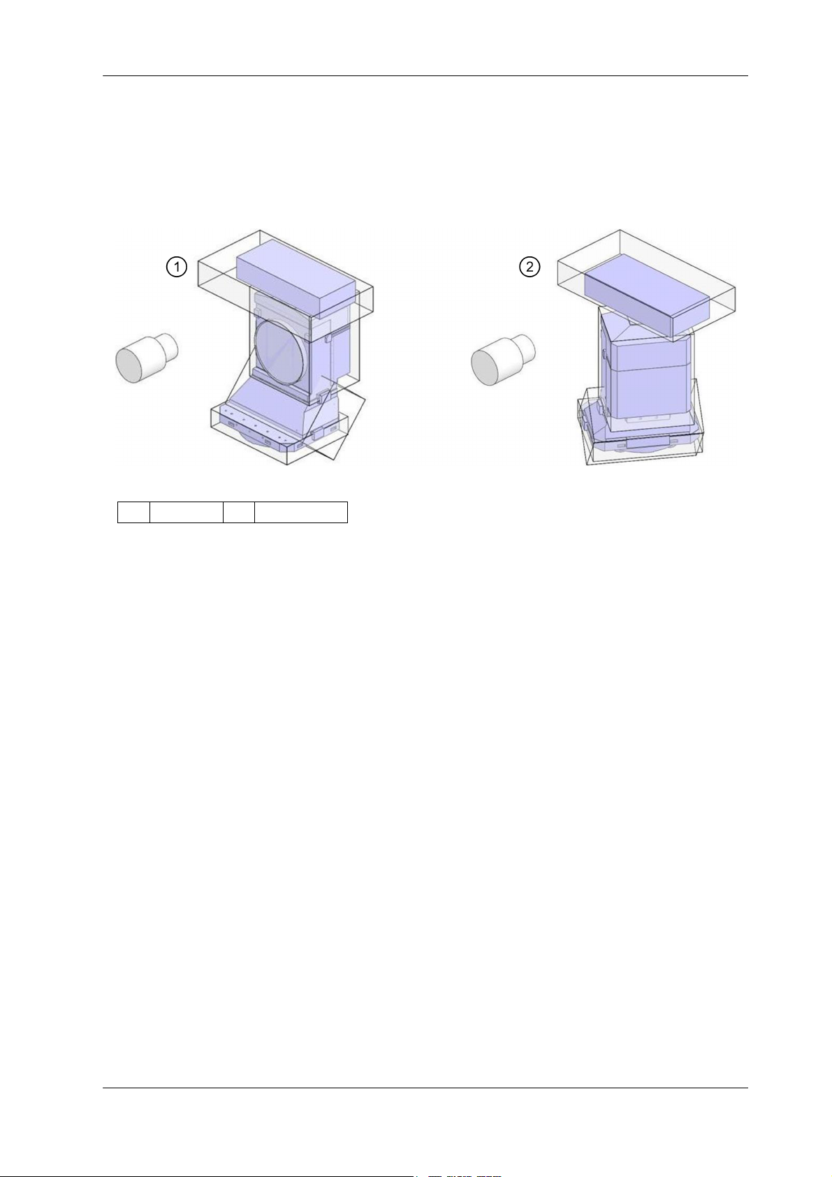
Legend
[1] The pallet part
does not apply.
CAUTION!
When Center of Rotation Axis Measurement is used, the Crash Check Alarm might be generated, because the spindle approaches to the table extremely. In such case, please operate it carefully after 3D crash avoidance mode is temporarily turned off.
CAUTION!
For the table with the chuck, the pallet gripped to chuck do not apply to the 3D crash
avoidance function.
Especially, about the RWH or 1-face angle plate with clamping system D of Work Holding
Pallet System, the pallet part does not apply to the 3D crash avoidance function.
Fig. 3-1: The example for the RWH with Clamping system D with Work Holding Pallet System
0847C-1610 (en) MAKINO
Page 17
OPERATIONAL NOTES 3-3
Legend
[1] B: 0 deg [2] B: -120 deg
NOTICE! In a92-5XR, the shape model for the collision check is greatly set to include the range of
motion though Terminal box on RWH moves by rotating B axis (see “Fig. 3-2: The shape
model of terminal box on B axis in a92-5XR”).
Fig. 3-2: The shape model of terminal box on B axis in a92-5XR
NOTICE! The distance in which the collision with the object is detected is as follows for operation
safety.
These change by the part.
• Objects in machining area: 10 mm or more
• Tool and Table side object: 10 mm or more
• Limitation area(*) and Table side object: 10 mm or more
• Limitation area(*) and Tool: 0 mm or more
(*) Area where work and fixture are protected (refer to chapter “7 Z AXIS COLLISION
AVOIDANCE FUNCTION”).
It is necessary to invalidate the function temporarily when it is necessary to cut it at the
position in which the distance becomes shorter than the above-mentioned setting.The
presence of collision need to be confirmed. The machining need to be executed safely.
(Refer to chapter “4 SWITCHING ON/OFF THE 3D CRASH AVOIDANCE MODE”.)
There are the following methods in the effective return of the function promptly after the
machining ends or manual interruption.
- Function button.
- M1401 command in MDI mode.
- M30 or NC reset button (machine parameter No. 2075=1).
MAKINO 0847C-1610 (en)
Page 18

3-4 OPERATIONAL NOTES
0847C-1610 (en) MAKINO
Page 19

SWITCHING ON/OFF THE 3D CRASH AVOIDANCE MODE 4-1
4 SWITCHING ON/OFF THE 3D CRASH AVOIDANCE MODE
Switching ON/OFF the 3D crash avoidance function can be performed either by M codes or by a function
button.
4.1 M Codes
M code Name Explanation
M1400 3D Crash Avoidance Mode Off Turns Off 3D Crash Avoidance mode
M1401 3D Crash Avoidance Mode On Turns On 3D Crash Avoidance mode
Table 4-1:
4.2 Function Button
“3D Crash Avoidance Mode” (On/Off).
Fig. 4-1:
NOTICE! The last commanded mode change becomes effective regardless of whether it was done
by an M code or by the function button.
Status of 3D Crash Avoidance Mode at Power ON can be specified by the machine parameter No. 02073.
NOTICE! It is necessary to turn On the function again either by M1401 “3D Crash Avoidance Mode
On” or by the function button at the “Function” screen, after it was turned Off either by
M1400 “3D Crash Avoidance Mode Off” or by the function button at the “Function”
screen.
MAKINO 0847C-1610 (en)
Page 20
4-2 SWITCHING ON/OFF THE 3D CRASH AVOIDANCE MODE
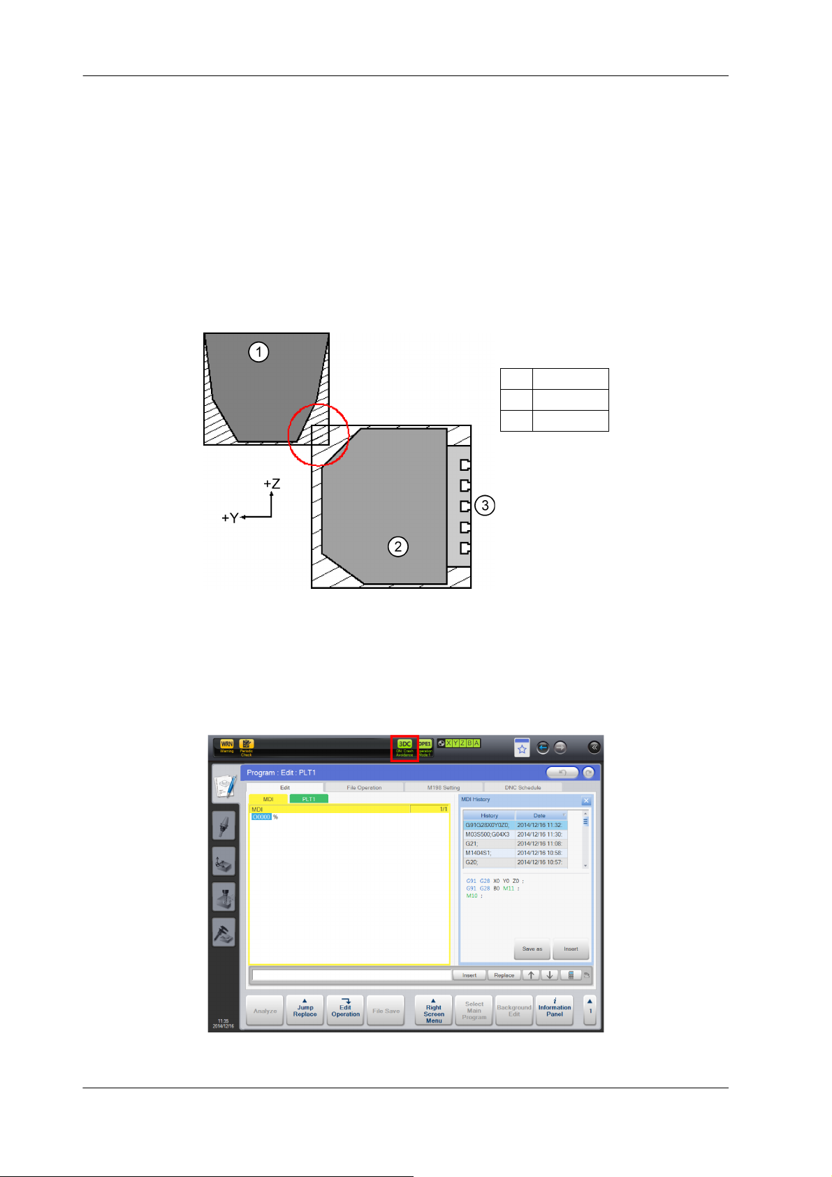
Legend
[1] Spindle
[2] Table
[3] A–90deg.
NOTICE! 3D Crash Avoidance function will not run properly if it is commanded when 3D Crash
Avoidance check areas are superposed as shown by ○ at the picture below, until superposed areas are not drawn apart.
This function should be turned On when the distance between structural elements is
200 mm or more.
This is valid during machine’s start-up as well. Machine’s power supply should be
turned Off in a position when the distance between structural elements satisfies the
aforementioned limits.
Fig. 4-2: Example of superposition of 3D Crash Avoidance check areas
4.3 Verification of 3D Crash Avoidance State
Fig. 4-3: 3D crash avoidance active
0847C-1610 (en) MAKINO
Page 21
SWITCHING ON/OFF THE 3D CRASH AVOIDANCE MODE 4-3
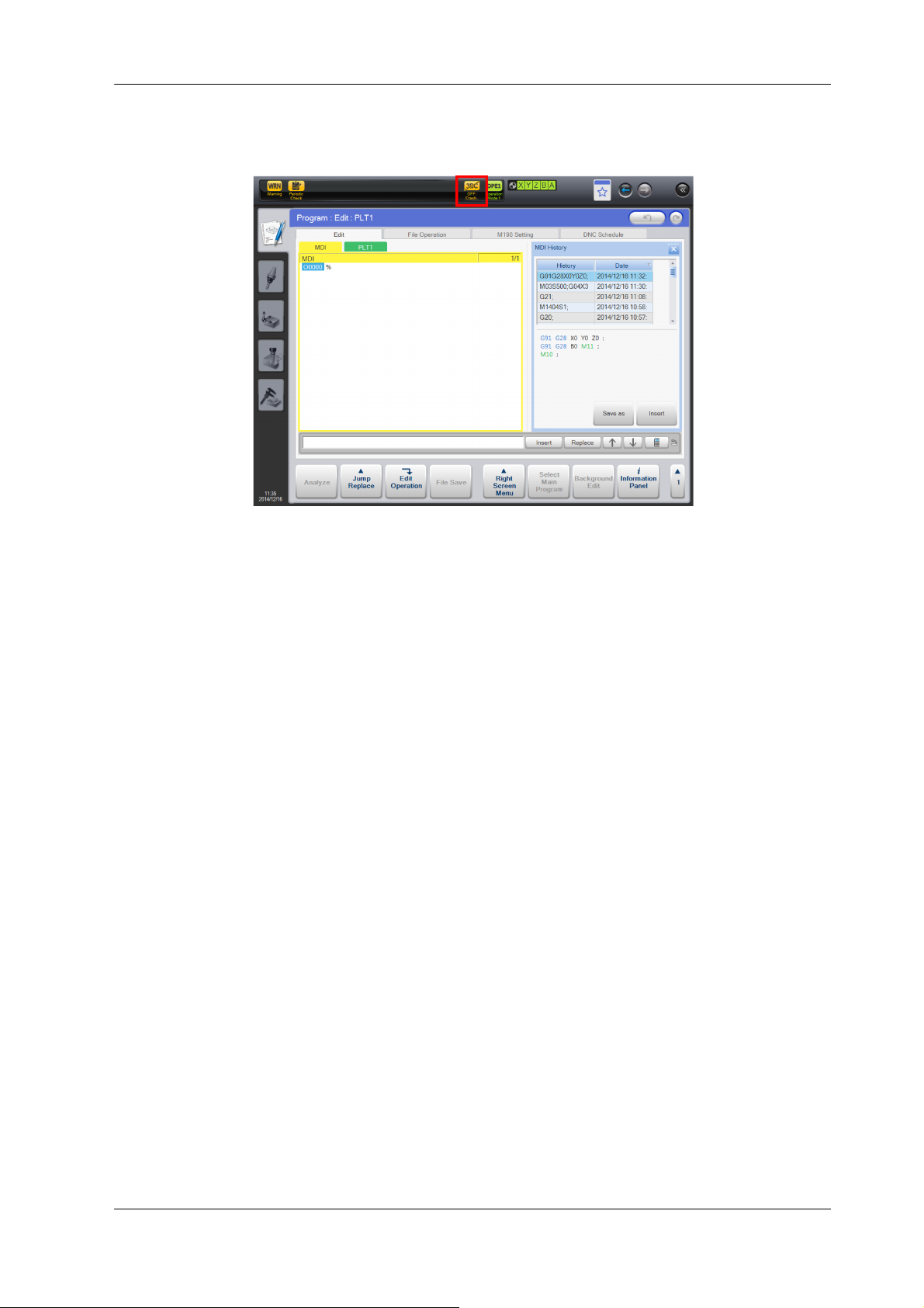
Fig. 4-4: 3D crash avoidance deactivated
In the above figures,
- when the 3D crash avoidance mode is On (active), [3DC] has green background color and the function
button has yellow background color;
- when the 3D crash avoidance mode is Off (deactivated), [3DC] has yellow background color and the
function button has gray background color.
MAKINO 0847C-1610 (en)
Page 22

4-4 SWITCHING ON/OFF THE 3D CRASH AVOIDANCE MODE
0847C-1610 (en) MAKINO
Page 23

CRASH CHECK ALARM AND RECOVERY 5-1
5 CRASH CHECK ALARM AND RECOVERY
When Crash Check Alarm is generated by this function, the screen in Professional 6, like “Fig. 5-1: Example
for Crash Check Alarm display”, is displayed.
After Crash Check Alarm is generated, please change handle mode, move Spindle and Table to opposite
direction of crash, and reset the Crash Check Alarm by pushing the [RESET] button.
Fig. 5-1: Example for Crash Check Alarm display
NOTICE! When Crash Check Alarm is generated, the meaning of the object displayed by the alarm
is different according to the machine type.
MAKINO 0847C-1610 (en)
Page 24

5-2 CRASH CHECK ALARM AND RECOVERY
0847C-1610 (en) MAKINO
Page 25

USE OF TOOL SHAPE DATA TRANSFER FUNCTION 6-1
6 USE OF TOOL SHAPE DATA TRANSFER FUNCTION
When an automatic tool change is performed, it is possible to attach a simplified cylindrical tool model to
the spindle configuration model using tool length and tool radius data of the “Tool data” screen of Professional 6.
Due to this function it becomes for example possible to prevent intrusion of the Z axial tool into the table.
This functional option is disabled at shipping from the factory.
NOTICE! This function is enabled to set 1 for machine parameter, No. 2081.
3D crash avoidance function is not applied to tool holders.
NOTICE! If you done dressing in G5 that this function is enabled, there is a possibility the Crash
Check Alarm is generated.
If you done dressing, please set off to Spindle-Table Crash Avoidance mode temporarily.
NOTICE! In automatic non-contact tool measuring device (separate-type) of D500, 3D crash avoid-
ance mode isn’t turned off while being measuring tool length.
Therefore, when the value of tool length or tool radius in tool data screen is larger than an
actual value or “0”, there is a possibility that Crash Check Alarm is generated while measuring it.
Please set the value of appropriate tool length or tool radius.
NOTICE! The tool model is set to the position where W axis is a reference position on the machine
attached the bar spindle.
Therefore, when the machine is used with the bar spindle extended, please add length
value of the bar spindle’s extension to the tool length data.
6.1 Timing of Tool Shape Data Transfer Function
This option can be enabled by changing the machine parameter No. 2081.
Tool geometrical model is created when there is some tool in the spindle (when pot is not the escape pot
or pot number is other than 0).
Specifically, tool shape data are renewed at the following instances:
- When an operator enters or edits either of tool length H, tool radius D, tool length wear HW, radial wear
DW values directly at the “Tool Data” screen of Professional 6.
- When tool length H or tool radius D of the spindle tool are changed by the NC tool measurement pro-
gram.
- When spindle pot number changes as a result of ATC action.
- When an operator changes spindle pot number at “Maintenance” screen of Professional 6.
- When upper level computer changes spindle tool shape data.
- When the machine power supply is turned ON.
- When emergency state is released.
- When 3D crash avoidance mode is turned ON.
NOTICE! Tool shape data is not changed at tool change done by manual tool clamp / unclamp.
Please set an appropriate value again in tool data screen.
MAKINO 0847C-1610 (en)
Page 26

6-2 USE OF TOOL SHAPE DATA TRANSFER FUNCTION
6.2 Tool Length, Tool Radius Data Handled by Tool Shape Data Transfer Function
Overall tool length transferred to CNC is calculated as tool length H plus length wear HW.
Similarly, overall tool radius transferred to CNC is calculated as tool radius D plus radial wear DW.
If calculated overall tool length turns out to be zero, it is substituted by the setting value of the machine
parameter No. 2085. Similarly, if calculated overall tool radius turns out to be zero, it is substituted by the
setting value of the machine parameter No. 2086.
Regardless of the machine specification (metric or inch), the values of the machine parameters No. 2085,
2086 are set in ten thousandths of a millimeter. At machines with inch specification their setting values are
automatically converted into inches by Professional 6.
NOTICE! When tool shape data transfer function is used, all tool length and radius values at the
“Tool Data” screen must be specified as measured from the gauge line to the farthest
point of a cutting edge as well as the largest radii respectively.
NOTICE! If there is a mismatch between the machine specification set by the machine parameter
No. 0073 and the current CNC units switched by G20/G21 codes, the tool shape data
transfer is blocked and the machine alarm No. 410011 is generated.
NOTICE! Machine parameter No. 2085 and No. 2086 need to be set more than 0 mm.
NOTICE! When negative values are input to tool length H or tool radius D, the alarm occurs.
Positive values need to be set to tool length (check) and tool diameter (check).
(The machine parameter No. 2076=1.)
REMARK More effective operation due to prevention of tool data related mistakes can be achieved
by simultaneous use of the Standard Tool Length Function.
REMARK When tool length measurement device is attached, the result of a measurement is auto-
matically input into tool data screen by setting it to “The tool data transfer is on the machine side.” just after measuring tool length.
6.3 Tool Length (Check), Tool Radius/Diameter (Check) of Tool Shape Data Transfer Function
Data used as tool offset value and data used for this function can be separately set.
In this case, set the value to the column of Tool Length (Check) and Tool Radius/Diameter (Check) displayed
on the tool data screen of Professional 6. (Hereafter, the input data is called “Collision Check Data”.)
When the value of Collision Check Data is “0”, the tool model is made by using the value of tool length H
and tool radius D displayed on the tool data screen. At this time, when the value of tool length H and tool
radius D are “0”, the tool model is made by using the value of machine parameter No. 2085 and No. 2086.
The method of inputting the tool radius/diameter of Collision Check Data can be set by machine parameter No. 76.
0847C-1610 (en) MAKINO
Page 27

USE OF TOOL SHAPE DATA TRANSFER FUNCTION 6-3
NOTICE! When machine parameter No. 2076 is “1”, this specification is effective.
When shipping it, machine parameter No. 2076 is “0” (specification of paragraph “6.2 Tool
Length, Tool Radius Data Handled by Tool Shape Data Transfer Function”).
NOTICE! When machine parameter No. 2076 is “1”, the tool data only of the tool length and tool
radius/diameter is transferred.
The tool ware data is not included in the calculation.
NOTICE! When this specification is used, tool length H and tool radius D shown in paragraph “6.1
Timing of Tool Shape Data Transfer Function” indicate Collision Check Data.
NOTICE! When the tool attaches to the attachment such as the angle head, the Collision Check
Data cannot be used.
6.4 Use of Tool Shape Data Transfer Function in dummy pot
If the actual number of tools used is the same as the available tool storage capacity, tool geometrical
model is created even if pot number of spindle tool is dummy pot number.
NOTICE! When machine parameter No. 2077 is “1”, this specification is effective.
When shipping it, machine parameter No. 2077 is “0” (tool geometrical model is none in
the dummy pot).
MAKINO 0847C-1610 (en)
Page 28

6-4 USE OF TOOL SHAPE DATA TRANSFER FUNCTION
0847C-1610 (en) MAKINO
Page 29
Z AXIS COLLISION AVOIDANCE FUNCTION 7-1
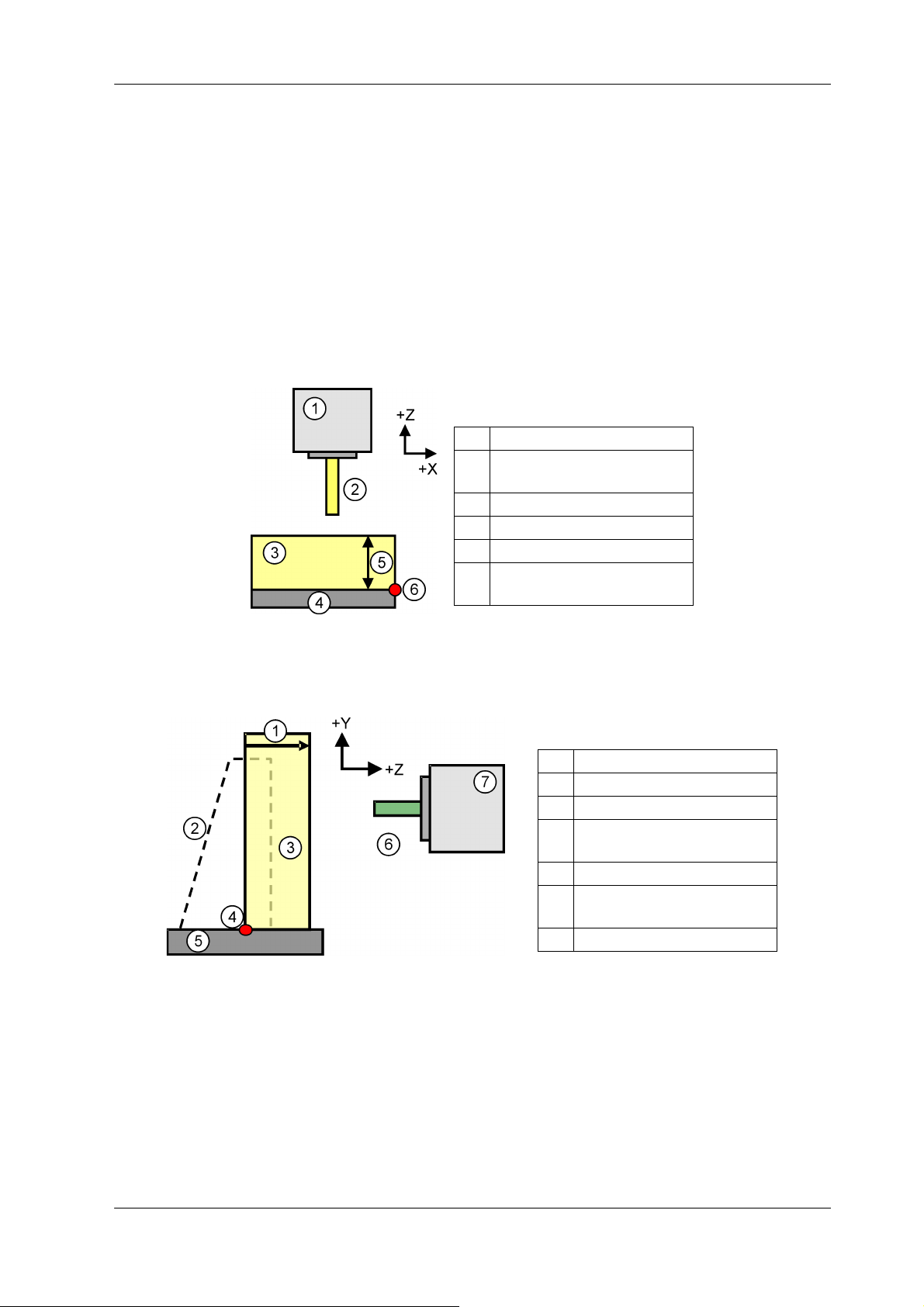
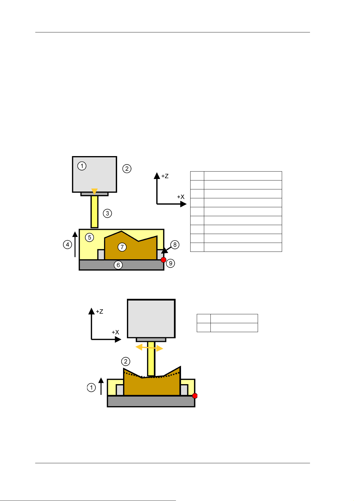
Legend
[1] Spindle
[2] Tool model (Tool shape data
transfer function)
[3] Limitation area
[4] Table
[5] Set using M code
[6] Reference postion Z
(Machine parameter N2064)
Legend
[1] Set using M code
[2] Angle plate etc.
[3] Limitation area
[4] Reference postion Z
(Machine parameter N2064)
[5] Table
[6] Tool model (Tool shape
transfer function)
[7] Spindle
7 Z AXIS COLLISION AVOIDANCE FUNCTION
Z Axis Collision Avoidance Function is a function which allows setting of a limitation area in order to avoid
collision between the tool tip and the table.
It is possible to create the limitation area with this function in order to prevent the collision through setting with an M code the area’s height, which is measured from the Z reference position, which is defined
by the machine parameter beforehand.
After the limitation area has been set, an Crash Check Alarm will be generated during machine operation
every time the tool tip is about to intrude in the range of the set Z machine coordinates. Therefore this
function allows preventing the tool tip’s piercing into the work in Z direction due to an erroneously set
workpiece origin offset values.
Fig. 7-1: Vertical type
Fig. 7-2: Horizontal type
NOTICE! Z axis collision avoidance Function cannot be used if 3D Crash Avoidance mode is not ef-
fective.
REMARK Set “0 (3DC)” to the machine parameter No. 02168 if this function is used during 3D Crash
MAKINO 0847C-1610 (en)
Avoidance mode.
Page 30
7-2 Z AXIS COLLISION AVOIDANCE FUNCTION
Legend
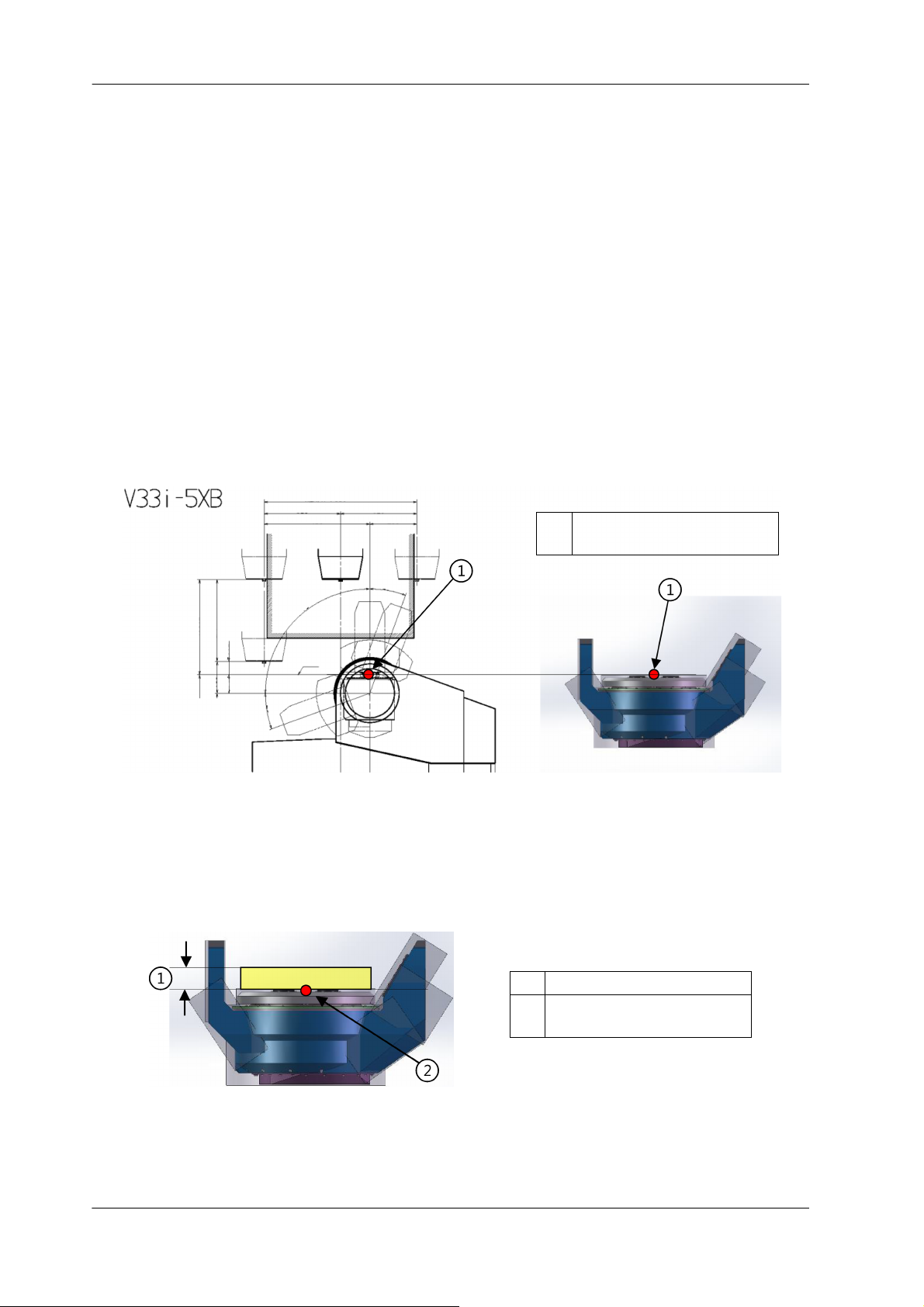
[1] Reference position Z
(Machine parameter N2064)
EROWA ITS CHUCK TYPE
(ER-007625)
406.2
350
Z-axis stroke
135
78.8 56.2
Contact
face
90°
20°
20°
200
325325
450
X-axis stroke 650
Legend
[1] Height of the pallet
[2] Reference position Z
(Machine parameter N2064)
REMARK More effective operation can be achieved using the Z Axis Collision Avoidance Function
together with the Tool Shape Data Transfer Function (chapter “6 USE OF TOOL SHAPE
DATA TRANSFER FUNCTION”).
REMARK If ATC is executed with Z axis collision avoidance function set, there is a possibility that the
Crash Check alarm is generated according to the tool length.
Cancel the Z axis collision avoidance function if ATC is executed.
REMARK For a series, M1404 might be executed before the axis movement is completed. Machine
alarm 311027 is generated for the above situation.
In that case, please add G53 in front of M1404.
REMARK Reference position Z (machine parameter N2064) is set to the face of the pallet at ship-
ment.
The following setting is set for V-5XB (for example, V33i-5XB, V56i-5XB, etc.), and D500
with work holding pallet specification.
Fig. 7-3: Example for reference position Z about V33i-5XB and D500 with work holding pallet
REMARK At shipment, limitation area has been set to the height of the pallet, specified from MAK-
INO.
The following setting is set for D500 with work holding pallet specification.
Fig. 7-4: Example for D500 with work holding pallet at shipment
0847C-1610 (en) MAKINO
Page 31
Z AXIS COLLISION AVOIDANCE FUNCTION 7-3
Legend
[1] Spindle
[2] Limitation area
[3] Table
[4] 100 mm (inch)
[5] Reference postion Z
(Machine parameter N2064)
7.1 Z Axis Collision Avoidance Function Setting
Switching this function ON/OFF can be performed either by M codes or by a function button.
M code Name Explanation
M1404 S_ Z Axis Collision Avoidance Setting Sets the limitation area of Z Axis Collision
Avoidance
Table 7-1:
M1404 S “L offset value from the table plane, mm or inch (depending on the mode)”
Sets the limitation area at of height L as measured from Z reference position. Positive values must be commanded.
Program example: M1404 S100;
- Limitation area’s height is 100 mm or 100 inch (“Fig. 7-5: Limitation area”)
- Additionally, by changing the machine parameter No. 2070, it is also possible to express values smaller
than 1 mm (1 inch) by multiplying the argument S by a coefficient
NOTICE! It is necessary to set the Z reference position with the machine parameter No. 2064.
Fig. 7-5: Limitation area
NOTICE! If the function is commanded in the situation when the tool model and the limitation area
overlap, the function will not perform properly until they are drawn apart.
Argument S value of the limitation area must be set about several mm more greatly.
MAKINO 0847C-1610 (en)
Page 32
7-4 Z AXIS COLLISION AVOIDANCE FUNCTION
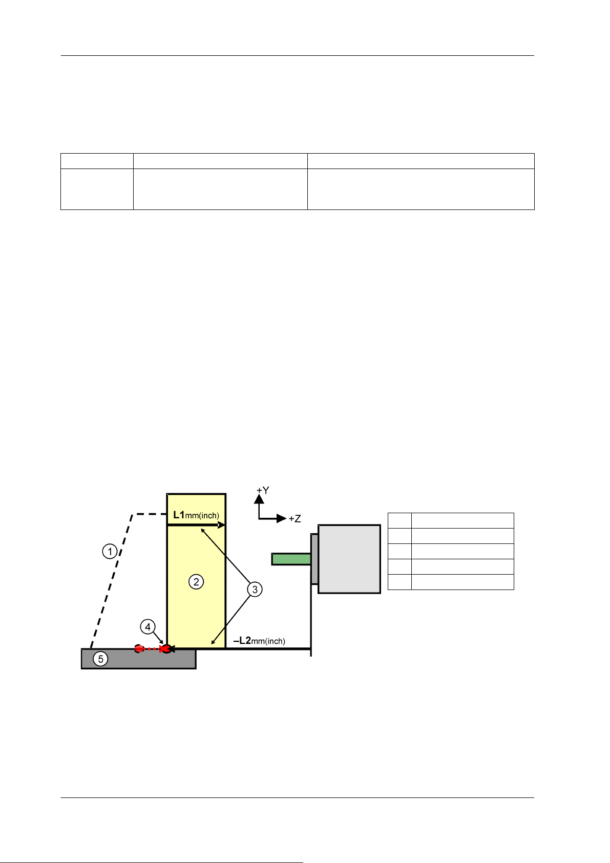
Legend
[1] Angle plate etc.
[2] Limitation area
[3] Set using M code
[4] Reference postion Z
[5] Table
7.2 Reference Position Z Setting according to M Code
It is possible to set the reference position Z of the limitation area by M code command in paragraph “7.1
Z Axis Collision Avoidance Function Setting”.
M code Name Explanation
M1404 S_T_ Z Axis Collision Avoidance Setting Sets the limitation area of Z Axis Collision Avoid-
ance. (The command position of argument T becomes reference position.)
Table 7-2:
M1404 S “L1” T “L2 reference position Z mm or inch (depending on the mode)”
- When T is commanded, the limitation area of “L1” in width is made. At this time, reference position Z is
assumed to be machine coordinate value “–L2”.
- When T isn’t commanded or T command is “T0”, the limitation area where machine parameter No. 2064
is assumed to be reference position Z is made.
NOTICE! Reference position Z that can be set is transformed into a negative value.
At this time, when argument T is set, change reference position Z to a positive value, and
command.
REMARK The change in reference position by T code is an argument of an effective one shot until
being canceled or being commanded M1404 again.
Fig. 7-6: Example for command
Program example
M1404S100T500
- The height of the limitation area becomes 100 mm or 100 inch.
- The reference position Z becomes “machine coordinate value –500 mm or –500 inch”.
0847C-1610 (en) MAKINO
Page 33

Z AXIS COLLISION AVOIDANCE FUNCTION 7-5
- Additionally, by changing the machine parameter No. 2070, it is also possible to express values smaller
than 1 mm (1 inch) by multiplying the argument S and T by a coefficient.
M1404S0T500 or M1404T500
- Argument T is disregarded, and the limitation area is canceled.
M1404S100T0
- The machine parameter No. 2064 is assumed to be reference position Z, and the limitation area of
100 mm or 100 inch in height is generated.
7.3 Cancel of the Limitation Area of Z Axis Collision Avoidance Function
M1404........................Cancels the function. (The same is “M1404 S0”).
Function button....It is possible to cancel the limitation area of the Z Axis Collision Avoidance Function
from Professional 6 Function screen.
It is also possible to cancel the limitation area by NC reset or Power off.
Refer to the machine parameter No. 2069 (chapter “9 MACHINE PARAMETERS”) for details.
Fig. 7-7: Example of cancel button of the Z Axis Collision Avoidance Function
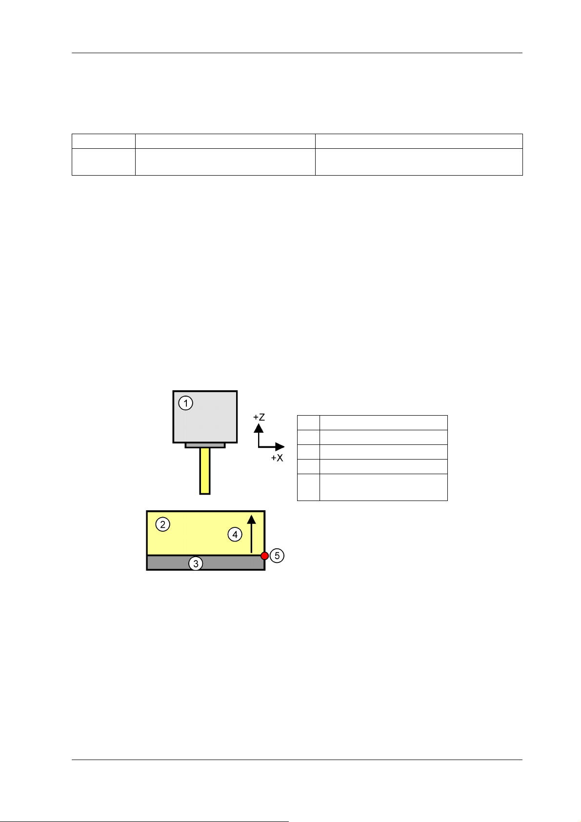
7.4 Application Example of Limitation Area of Z Axis Collision Avoid-
ance Function
The application example is shown below.
In N2, Height from the Z reference position to which the tool tip is allowed to approach is set to
argument S.
After the initial approach is finished, in N4, the height of the area which is supposed to be outside the machining area, as measured from the table, is set to prevent collision. In N7 the limitation area is cancelled.
MAKINO 0847C-1610 (en)
Page 34
7-6 Z AXIS COLLISION AVOIDANCE FUNCTION
Legend
[1] Spindle
[2] Approach
[3] Tool model
[4] 100 mm
[5] Limitation area
[6] Table
[7] Workpiece before cutting
[8] Fixture
[9] Reference position Z
Legend
[1] Machining area
[2] 30 mm
Program example
O1000 (units are mm)
N1 T1 M6;
N2 M1404 S100; (“Fig. 7-8: N2”)
N3 G90 G43 G54 X0 Y0 Z0 H1; (initial approach)
N4 M1404 S30; (“Fig. 7-9: N4”)
M198 Pxxxx; (machining program)
N6 G91 G28 Z0;
N7 M1404; (Cancel of the Z Axis Collision Avoidance)
N8 M30;
Fig. 7-8: N2
0847C-1610 (en) MAKINO
Fig. 7-9: N4
Page 35

Z AXIS COLLISION AVOIDANCE FUNCTION 7-7
Legend
[1] Angle plate [4] B axis rotary / index
[2] Table [5] B axis rotation
[3] Limitation area
7.5 Motion of the Limitation Area of Z Axis Collision Avoidance Func-
tion for Workpiece Rotation Type Machines with 4 or 5 Axes
The limitation area does not rotate synchronously with the rotational axis at 4/5 axes machines of a/A /
MCC / MCD series.
However, the limitation area can rotate synchronously with rotational axes at five-axial workpiece rotation
type machines of D500, V-5XB, A66E-5XD, a51-5XU, G5, G10.
MAKINO 0847C-1610 (en)
Fig. 7-10: Rotation of the limitation area
Page 36

7-8 Z AXIS COLLISION AVOIDANCE FUNCTION
7.6 Verification of Z Axis Collision Avoidance Function
It is possible to verify the limitation area setting state by the color of 3DC indicator.
Fig. 7-11: Z Axis Collision Avoidance is effective
Fig. 7-12: Z Axis Collision Avoidance is disabled
In the above figures,
- when the Z Axis Collision Avoidance Function is On (active), [3DCZ] has green backcolor.
- when the Z Axis Collision Avoidance Function is Off (deactivated), [3DC] has green backcolor.
0847C-1610 (en) MAKINO
Page 37

OTHER FUNCTIONS DIFFERENT IN EACH MACHINE TYPE 8-1
Legend
[1] Y shift amount (No. 2093)
[2] Position of table shape be-
fore it changes
[3] Position of table shape af-
ter it changes
[4] (Y-STROKE)
8 OTHER FUNCTIONS DIFFERENT IN EACH MACHINE TYPE
8.1 Use of 3DC Y position setting function (ONLY MCC2013VG)
This function is that the model of the table, set beforehand, can be shifted to Y+ direction by an arbitrary
value of the operator. The height (amount) that shifts from the upper surface of the table in Y+ direction is
input to the machine parameter (No. 2093). And, you can avoid the crash of the things (nozzle and piping
etc.) on the table.
REMARK 3DC Y position setting function cannot be used if 3D Crash Avoidance Function is not ef-
NOTICE! When Y shift amount (No. 2093) of the table is set to 100 mm or more, there is a possibil-
MAKINO 0847C-1610 (en)
Fig. 8-1: Outline Figure of 3DC Y position setting function
fective.
ity that the spindle and the table crash.
Page 38

8-2 OTHER FUNCTIONS DIFFERENT IN EACH MACHINE TYPE
Legend
[1] Pallet No. 1
[2] Pallet No. 2
[3] APC
Legend
[1] Pallet No. 1
[2] Pallet No. 2
[3] Reference position Z
(Machine parameter 2064)
8.2 About Automatic Pallet Change (APC) of a/A series-5XR machines
After completing APC of a/A series-5XR machines, the model is changed to the shape model matched to
specifications of pallet in machining chamber automatically (“Fig. 8-2: Example for APC of a/A series-5XR
machines”).
Limitation area of the Z-Axis Collision Avoidance Function has following restrictions in this machine type.
- Limitation area is canceled automatically in working APC.
- Regardless of specifications such as RWH or WHP, Shape of limitation area is based on pallet part (“Fig.
8-3: Example for limitation area of a/A series-5XR machines”).
- The limitation area doesn’t rotate synchronously with the rotational axis (reference to paragraph “7.4
Application Example of Limitation Area of Z Axis Collision Avoidance Function”).
Fig. 8-2: Example for APC of a/A series-5XR machines
Fig. 8-3: Example for limitation area of a/A series-5XR machines
NOTICE! Initial value of reference position Z of the Z-Axis Collision Avoidance Function has been
set to distance from gauge line of spindle to the center of rotation of B-axis.
0847C-1610 (en) MAKINO
Page 39
OTHER FUNCTIONS DIFFERENT IN EACH MACHINE TYPE 8-3
Legend
[1] Main spindle [4] Tool
[2] Sub spindle [5] Table
[3] Change [6] Limitation area
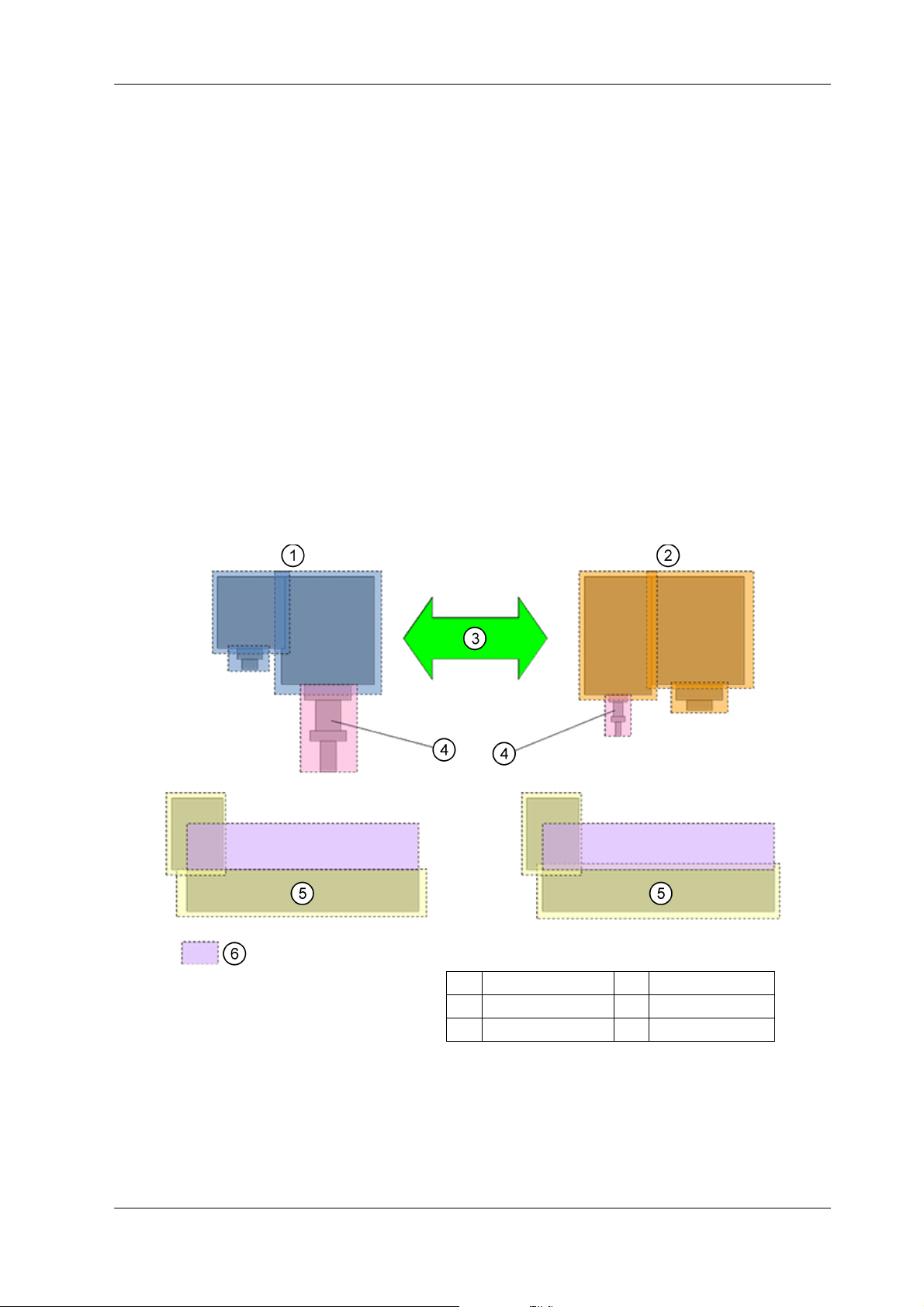
8.3 About Spindle Model Change in EG3010
It automatically changes into the spindle model matched to an effective spindle now in EG3010 (the machine that has a sub spindle).
Limitation area of Z axis remains after the switch of the spindle model.
When the tool shape data transfer function of chapter “6 USE OF TOOL SHAPE DATA TRANSFER FUNCTION” is used, and the data of the length or diameter of the tool is empty, the machine parameter to which
it refers with the main spindle and a sub-spindle is different.
Tool shape data transfer function
1. The main spindle
When Tool Length (Check) = Tool (H) = 0, it refers to machine parameter No. 2085.
When Tool Diameter (Check) = Tool (D) = 0, it refers to machine parameter No. 2086.
2. The sub spindle
When Tool Length (Check) = Tool (H) = 0, it refers to machine parameter No. 2089.
When Tool Diameter (Check) = Tool (D) = 0, it refers to machine parameter No. 2088.
Fig. 8-4: Image of spindle model change
MAKINO 0847C-1610 (en)
Page 40

8-4 OTHER FUNCTIONS DIFFERENT IN EACH MACHINE TYPE
8.4 About high-speed attachment specification in iQ300
It automatically changes into the spindle model matched to an effective spindle now in iQ300 (the machine that has a high-speed attachment).
Limitation area of Z axis remains after the switch of the spindle model.
When the tool shape data transfer function of chapter “6 USE OF TOOL SHAPE DATA TRANSFER FUNCTION” is used, and the data of the length or diameter of the tool is empty, the machine parameters to
which it refers are same.
0847C-1610 (en) MAKINO
Page 41

MACHINE PARAMETERS 9-1
9 MACHINE PARAMETERS
The following machine parameters must be set in order to enable 3D crash avoidance function. Note that
only default setting values are listed below.
No. 00076 Tool Radius/Diameter (Check) Type
Description 0:Radius
1:Diameter
Setting Set as desired (Standard setting: 0).
Power Off Required
No. 02064 Reference position of the Z Axis Collision Avoidance Setting Function
Description Sets the Z coordinate in machine coordinates for the reference position of the Z Axis
Collision Avoidance Setting function (unit: mm).
Please set as the distance (negative value) as measured from the spindle gauge line
when machine is in auto zero reference position.
Setting For example Z-600 mm: -600.0
Power Off Not Required
No. 02069 Cancel Conditions of the Z Axis Collision Avoidance Setting Function
Description Defines whether to cancel the Z Axis Collision Avoidance Setting function at NC Reset
or M30.
0: Do Nothing
1: Cancel the function
Setting Standard setting: 0
Power Off Not Required
No. 02070 Coefficient of the Entered Values of the Z Axis Collision Avoidance Setting Function
Description Sets the coefficient of the values for the Z Axis Collision Avoidance Setting Function
entered with S code / T code of the M1404 code.
Setting values vs. coefficients.
0:1
1:0.1
2:0.01
3:0.001
4:0.0001
Setting Standard setting: 0
Power Off Not Required
MAKINO 0847C-1610 (en)
Page 42

9-2 MACHINE PARAMETERS
No. 02073 Status of 3D Crash Avoidance Mode at Power ON
Description Status of 3D Crash Avoidance Mode at Power ON
0: Mode Off
1: Mode On
2: Restore the status which was effective at the last power shut-down
Setting Set as desired (Standard setting: 1).
Power Off Required
No. 02075 Status of 3D Crash Avoidance Mode at NC reset
Description Status of 3D Crash Avoidance Mode at NC reset
0: Mode Off
1: Mode On
2: No change of mode
Setting Set as desired (Standard setting: 2).
Power Off Required
NOTICE! NC reset may be executed automatically with One touch functions etc.
No. 02076 Enable Tool Length (Check) and Radius (Check) Data for 3DC
Description Use or not Tool Length(Check) and Tool Radius(Check) data with 3DC is set.
0: Do not use
1: Use
Setting Standard setting: 0
Power Off Not Required
No. 02077 Enable Tool Length & Diameter Transfer Function for T0 Pot
Description Use or not Tool Length and Diameter Transfer Function for T0 pot is set.
0: Do not use
1: Use
Setting Standard setting: 0
Power Off Required
No. 02081 Existence of tool length / diameter transfer function for 3D Crash Avoidance function
Description 0: Not Effective
1: Effective
Setting (Standard setting: 0)
Power Off Required
0847C-1610 (en) MAKINO
Page 43

MACHINE PARAMETERS 9-3
No. 02085 Tool length value for Collision Check
Description Define the tool length value which is used if the calculated total length of the spindle
tool is 0 for below functions (Set other than 0.)
- Tool Shape Data Transfer Function in Spindle-Table Crash Avoidance Function
- Simplified Tool Setting in Collision Safeguard
Setting For example 100 mm: 100.0
Power Off Required
No. 02086 Tool diameter value for Collision Check
Description Define the tool diameter value which is used if the calculated total diameter of the
spindle tool is 0 for below functions (Set other than 0.)
- Tool Shape Data Transfer Function in Spindle-Table Crash Avoidance Function
- Simplified Tool Setting in Collision Safeguard
Setting For example 100 mm: 100.0
Power Off Required
No. 02088 Tool diameter value for CNC built-in 3-dimensional Crash Avoidance function (Sub spindle)
Description Tool diameter value for CNC built-in 3-dimensional Crash Avoidance function
(Set value other than 0. Regardless of machine’s inch / metric specification, set this
value in mm)
Setting For example 100 mm: 100.0
Power Off Required
No. 02089 Tool length value for CNC built-in 3-dimensional Crash Avoidance function (Sub spindle)
Description Tool length value for CNC built-in 3-dimensional Crash Avoidance function
(Set value other than 0. Regardless of machine’s inch / metric specification, set this
value in mm)
Setting For example 100 mm: 100.0
Power Off Required
No. 02093 Distance Between the Table and the Work in Y Axis Direction
Description Defines the distance between the table and the work in the 3DC Y position setting
function for table collision avoidance.
Set a positive value that contains 0.
Setting Standard setting: 0
Power Off Required
MAKINO 0847C-1610 (en)
Page 44

9-4 MACHINE PARAMETERS
No. 02168 Base Function of Z Axis Collision Avoidance
Description Set in which function Z Axis Collision Avoidance is used.
0: 3D Crash Avoidance
1: Collision Safeguard
Setting Standard setting: 0
Power Off Required
0847C-1610 (en) MAKINO
Page 45

MACHINE ALARMS 10-1
10 MACHINE ALARMS
The machine alarms related to this function are described in this section.
Alarm Number 311000
Alarm Message 3D Crash Avoidance Data Setting Abnormal (Mode)
Alarm Cause 3D Crash Avoidance mode is disabled.
Recovery Procedure Check 3D Crash Avoidance mode.
Alarm Number 311001
Alarm Message 3D Crash Avoidance Data Setting Abnormal (S-Code)
Alarm Cause 3D Crash Avoidance commanded data is abnormal.
Recovery Procedure Check commanded data.
Alarm Number 311002
Alarm Message 3D Crash Avoidance Data Setting Abnormal
Alarm Cause 3D Crash Avoidance data were not set correctly.
Error Codes:
3:Data Number Error. Check data number and correct it.
5:Data Error. Check data and correct it.
6:The option of this function does not exist.
13:Proccess was rejected by CNC.
Recovery Procedure Check data number.
Alarm Number 311003
Alarm Message 3D Crash Avoidance Function Related Settings Change Abnormal
Alarm Cause 3D Crash Avoidance related settings change was not completed in specified
time.
Recovery Procedure Contact the Service Center.
Alarm Number 311007
Alarm Message CNC address setting failure for spindle tool diameter / length transfer
Alarm Cause Setting of the machine parameter No.2066 is incorrect or Focas function for
spindle tool diameter / length transfer address setting has failed. Spindle
tool diameter / length transfer is impossible.
Recovery Procedure Check machine and NC parameter and other settings related to CNC built-in
3-dimensional Crash Avoidance function.
MAKINO 0847C-1610 (en)
Page 46

10-2 MACHINE ALARMS
Alarm Number 311008
Alarm Message Spindle tool diameter / length / wear data for CNC built-in 3-dimensional
Crash Avoidance function reading failure
Alarm Cause Failed to read some of the spindle tool diameter / length / wear data for CNC
built-in 3-dimensional Crash Avoidance function. Due to this failure spindle
tool diameter / length / wear data will not be transferred to the CNC and the
correct execution of the 3-dimensional Crash Avoidance function is not ensured.
Recovery Procedure Verify correctness of diameter / length / wear data of the spindle tool, then
check correct transfer of these data when spindle tool is changed.
Alarm Number 311009
Alarm Message Diameter / length data of CNC built-in 3-dimensional Crash Avoidance func-
tion read-back failure
Alarm Cause Failed to read back immediately after writing some of the diameter / length
data of CNC built-in 3-dimensional Crash Avoidance function. Due to this
failure the correct execution of the 3-dimensional Crash Avoidance function
is not ensured.
Recovery Procedure Verify correctness of diameter / length / wear data of the spindle tool, then
check correct transfer of these data when spindle tool is changed.
Alarm Number 311011
Alarm Message Z Axis Collision Avoidance Setting Failure
Alarm Cause Could not perform settings because the machine was moving.
Recovery Procedure Command again after having confirmed that the machine is stopped.
Alarm Number 311012
Alarm Message Data Reading Failure with the Z Axis Collision Avoidance Function
Alarm Cause Failed to read from CNC some of the data for Z Axis Collision Avoidance
function. Due to this failure the correct execution of the Z Axis Collision
Avoidance function is not ensured.
Recovery Procedure Contact the service center.
Alarm Number 311013
Alarm Message Data Writing Failure with the Z Axis Collision Avoidance Function
Alarm Cause Failed to write from CNC some of the data for Z Axis Collision Avoidance
function. Due to this failure the correct execution of the Z Axis Collision
Avoidance function is not ensured.
Recovery Procedure Contact the service center.
0847C-1610 (en) MAKINO
Page 47

MACHINE ALARMS 10-3
Alarm Number 311015
Alarm Message Data Writing Failure with the 3DC Y Position Setting Function
Alarm Cause Failed to write to CNC some of the data for 3DC Y Position Setting function.
Due to this failure the correct execution of the 3DC Y Position Setting function is not ensured.
Recovery Procedure Contact the service center.
Alarm Number 311027
Alarm Message Z Axis Collision Avoidance Setting Failure
Alarm Cause Could not perform settings because the machine was moving.
Recovery Procedure Command again after having confirmed that the machine is stopped.
Alarm Number 410011
Alarm Message Inch/Metric Status Alarm
Alarm Cause Machine parameter No. 73 is different from the Inch/Metric status (G20/
G21).
Recovery Procedure Check the program.
MAKINO 0847C-1610 (en)
Page 48

10-4 MACHINE ALARMS
0847C-1610 (en) MAKINO
 Loading...