

Page 1

{
o
VERTICAL
MAKINO
MACHINING
INSTALLATION
CENTER
MANUAL
V1431I-I1E-XB
WARNING
/h
Do
1.
and
2.
Store
maintaining,
This
machine,
the
Japanese
retransfer
sell,
obtain
i
any
maintain,
not
understanding
this
manual
including
Foreign
or
required
inspect
this
a
in
inspecting
technical
Exchange
re-export
authorization
repair
or
manual.
clearly
or
repairing
and
of
controlled
this
marked
data
Foreign
or
approval.
machine
location
this
and
items,
for
machine.
software,
Trade
please
before
easy
may
Law.
contact
carefully
reference
subject
be
Prior
to
Makino
reading
when
to
any
re¬
to
Page 2

Installation
Manual
Fi/FI>
MACHINE
MODEL
CONTROLLER
COMPANY
manual
This
necessary
is
pre-installation
NAME
developed
TYPE
of
use
the
for
arrangements
Makino
for
F-Series
F3/F5
Professional
help
customers
machine.
to
5
and
guideinmaking
all
Release
1st
Revision(s)
Copyright
No
•
•
•
part
parties
to
Makino.
All
specifications
Every
at
for
attempt
the
time
information
Date:
©
of
Date:
this
other
of
August
26
-
manual
than
and
made
was
printing.
that
becomes
2009
All
Rights
may
be
whichitis
designs
ensure
to
specifications
As
incorrectorinaccurate
Reserved
reproduced
intended,
change
may
that
or
without
without
the
designs
and
transmitted
the
expressed
notice.
information
change,
after
by
any
means
written
publication
this
in
Makino
publication.
in
or
permission
was
is
not
responsible
any
correct
form
from
V1
431
1-11
E-XB
2
Page 3

)
)
Page 4
Installation
Contents
Manual
Fl/FS
1.
Introduction
1.1
Machine
Components
1
.2
Safety
2.
Introduction
2.1
Danger,
2.2
2.3
Installation
Specifications
3.
3.1
Introduction
3.2
Mechanical
3.3
Makino
3.4
General
Tooling
3.5
Pre
4.
Installation
Introduction
4.1
Characteristics
Precautions
Warning,
Safety
and
Professional
View
Specification
Process
Machine
and
Caution
Electrical
Dimensional
and
Function
Statements
Specification
and
5
Control
and
Specifications
Drawings
Symbols
5
5
5
6
6
6
9
12
12
13
16
19
30
31
31
Selecting
4.2
4.3
Foundation
4.4
Floor
Plan
Power
4.5
4.6
Transformer
Earthing/Grounding
4.7
4.8
Air
4.9
Machine
4.10
Service
Toolings
4.1
1
Coolant
4.12
4.13
Oil
4.14
Machine
4.15
Cables
Installation
4.16
Supply
Supply
Facilities
Requirements
Grease
and
for
Machine
the
Marking
and
and
(Option)
Handling
and
Fixtures
Requirements
and
Data
direct
Tooling
Location
Cables
Preparations
Facilities
server
communication
connection
Requirements
to
a
computer
FSE)
(By
without
a
network
HUB
31
33
34
34
36
37
37
38
38
38
55
55
56
57
58
4.17
Pre-Installation
V1431I-I1E-XB
Checklist
60
3
Page 5
Installation
Manual
F3/FIS
5.
Machine
5.1
5.2
5.3
5.4
5.5
5.6
Installation
6.
6.1
Delivery
Introduction
Container
Inspect
Unloading
5.4.1
5.4.2
5.4.3
5.4.4
5.4.5
5.4.6
Initial
Machine
Layout
the
Lifting
Lifting
Lifting
Lifting
Lifting
Lifting
Machine
Cleaning
Packing
Process
Introduction
Machine
and
the
Machine
the
Front
Chip
the
the
Rear
the
Transformer
Rolling
list
Moving
Coolant
Conveyor
tank
tank
64
65
65
66
66
66
69
70
71
72
73
75
.
75
76
76
6.2
6.3
6.4
6.5
6.6
6.7
General
Instructions
Installation
6.3.1
Installation
6.3.2
Installation
6.3.3
Installation
Installation
6.3.4
6.3.5
Installation
6.3.6
Installation
Procedure
Installation
Installation
Installation
conveyor
Process
ATC
of
Spindle
of
of
Transformer
Z
of
Z
of
Air
of
Machine
for
Procedure
Procedure
Procedure
covers
Oil
Cooler
axis
motor
Cable
axis
Dryer
forSSeries
for
for
(Option)
Leveling
Rear
Rear
chain
Coolant
coolant
coolant
tank
tank
tank
with
with
chip
hinge
bucket
(option)
belt/scrapper
.
Lift
up
76
76
76
78
84
85
86
87
93
95
97
chip
99
V1
431
1-11
E-XB
4
Page 6

Installation
1.
Introduction
Manual
Fi/FS
1.1
F-Series
rigidity
machining
The
achieved
axes
with
faster
operations
1.2
F-Series
which
servomotors:
•
•
•
•
•
•
•
Machine
machines
built
efficiency
main
characteristic
by
acceleration,
high
speed
ATC
Components
machines
machine
X-Axis,
The
moves
The
The
mounted
The
20000
Viewed
magazine
The
The
left
Y-Axis
Z-Axis,
spindle
rpm)
from
chip
electrical
accessible
neatly
routed
Characteristics
are
the
versatile
on
high
and
proven
speed,
and
special
design
especially
features
GI.3
sustainable
high
power
and
3-axis
are
are
comprised
an
which
and
carries
whichishousedonX-axis
the
to
is
with
the
on
disposal
locations
is
right.
the
Z-axis.
high
of
power
machine
left
the
istothe
cabinet,
the
into
table
speed
of
side
oilmatic,
the
at
column.
concepts
for
of
and
inter-plane
Makino
Machine
Vertical
bed,
of
integrated
and
with
22kW.
front,
the
and
chip
rear
Vertical
the
Die
machine,
the
SGI
machining
Professional5Control
Machining
achieve
to
Mold
and
Control,
geometrical
and
industry.
which
high
also
Function
Machining
column,
unit,
isonthe
moves
maximum
a
is
the
NC
operator
bucketatthe
hydraulic
and
side
Centers
and
the
comprises
moves
bed,
up
spindle
control
door
and
of
panel
is
front
pneumatic
machine.
the
of
and
at
tank,
Centers
productivity
high
contributes
rapid
axes
accuracy,
reducing
functions
of
fixed
Z
Y,
X,
the
the
Z-axis
back
down.
speed
on
center.
into
systems
The
axes
and
of
the
the
with
to
traverse
reducing
non
the
column
are
and
forth.
spindle
The
12000
right
130t
are
cable
high
and
high
productivity
cutting
for
type,
driven
the
rpm
side
and
front
located
and
hoses
reliability
high-speed
high
and
rates
cutting
simultaneous
the
by
spindle,
housing
(optionally
ATC
coolant
time
at
time
units
is
tank.
easily
are
and
are
with
of
V1
431
1-11
E-XB
5
Page 7

Page 8

Installation
Manual
Fi/FS
2.1
Introduction
chapter
This
environment.
Safety
thoroughly
personal
order
installing
Designate
personnel
strongly
everyone
2.2
precautions
understood
injury
to
install
this
specific
involvedinthe
recommended
and
Danger,
provides
and
and
the
machine
machine.
operators
kept
also
Warning,
Safety
2.
general
special
the
by
machine
operation,
that
near
safety
considerations
operator.
damage.
safely.
this
of
copy
a
the
of
machine
Caution
Precautions
guidelines
Careless
Read
Study
machine
maintenance
this
at
that,
if
all
for
use
pre-installation
this
safety
all
provide
and
and
Pre-Installation
all
times.
Statements
followed,
machining
of
precautions
thorough
inspection
Manual
the
and
promote
machine
Symbols
a
operations
may
Manual
and
functions
safety
this
of
easily
is
working
safer
must
result
thoroughly
before
training
machine.
accessible
for
in
It
be
a
in
all
is
to
important
is
It
understand
These
replaced
meaning
understand
hazards
safety
if
of
on
that
meaning
the
labels
they
are
each
meaning
the
F-Series
employees
all
of
must
damaged,
safety
of
is
shown
Danger,
never
statement.
the
be
defaced,
safety
Figure
in
recognize
Warning,
removed,
or
important
is
It
symbols.
2.1.
each
Caution.
and
covered
become
The
that
symbol
painted
or
all
of
safety
unreadable.
location
the
on
over,
Table
employees
safety
symbols
machine
and
presents
2.1
recognize
for
must
and
specific
and
be
the
V1
431
1-11
E-XB
6
Page 9
Installation
Manual
(!
Fi/F
*<c
-ÿO
<1
\
7ÿ
3
1
<
v
!
<ÿ
\
<£>
((
\
1
&
2
IP
Hr
s
\
;
#|
/ÿ
K
v
zKWARNING
zhWARNING
V1
431
1-11
®
Enterlng
E-XB
space
operation
oauso
death.
Turn
before
door
OFF
to
m
or
injury
opening
enclosed
improper
can
or
power
enter,
Figure
N>s
aro
Improper
tool
of
tool
during
leading
Injury.
Close
before
_
m
symbols
to
door
Carelessness
removing
can
workpiece
and
Machined
sharp
Use
removing
Locations
2.1:
lead
causing
care
ra
workpiece
and
workpiece.
to
falling
injury.
odges
can
when
of
whon
cut.
Safety
Insertion
can
be
ATC
to
cycling
cause
thrown
cycle,
serious
fully
>rwwa
ATC.
7
Page 10

Installation
Manual
F3/F!
Table
Statement
DANGER
WARNING
CAUTION
2.3
The
•
•
2.1:
Installation
following
Adhere
Make
.
installation
and
the
arrival
Definitions
Meaning
DANGER
means
instruction(s)
WARNING
the
result.
CAUTION
the
result.
information
strictly
thorough
a
the
of
Danger,
of
is
the
that
either
is
is
the
instruction(s)
_
the
is
instruction(s)
_
Safety
relatedtoinstallationofthe
is
installation
the
to
make
of
sure
check
to
machine.
Warning
most
severe
followed.
not
next
is
not
least
not
is
instructions
mechanical
the
that
&
severe
personal
level
followed
severe
followed
they
Caution
safety
_
safety
of
safety
and
working
are
statements
statement.
injury
statement.
severe
statement
damage
machining
provided
electrical
in
death
or
personal
to
the
in
units
good
statement
This
may
result
indicates
It
injury
indicates
and
the
equipment
center:
Pre-Installation
used
for
safe
conditions,
and
the
if
if
that
could
that
if
may
Guide.
machine
moving
before
Lifting
All
persons
but
is
not
All
•
All
•
Any
•
standards.
Slings
When
Never
•
Protect
•
Chains
Lifting
chains:
Never
•
Do
•
Do
•
Never
•
Use
•
Use
•
Safety
limited
lifting
lifting
lifting
using
exceed
slings
chains
exceed
drag
not
allow
not
twist
proper
chains
lifting
found
lifting
heavy
be
lifting
in
for
machinery,
must
must
stored
to
an
responsible
to
equipment
equipment
device
slings:
the
with
must
the
chains.
chains
chains
devicestoshorten
equipped
with
lifting
properly
be
inspected
be
to
be
capacity
padding
properly
capacity
become
attempt
enclosed
follow
must
machine
defective
any
of
when
any
of
tangled
shorten
to
chain's
a
rated
on
prevent
to
or
lifting
these
must
sling.
lifting
lifting
components,
the
for
a
regularly
be
objects
damage
chain.
kinked.
length.
their
length.
hooks.
safety
and
weight
scheduled
repaired
with
when
precautions.
work
being
lifted.
basis.
in
accordance
sharp
edges.
not
pieces:
use.
in
This
with
When
includes,
industry
using
Hooks
When
Never
•
Do
•
Destroy
•
431
V1
using
exceed
not
1-11
E-XB
hooks:
repair
and
lifting
the
lifting
discard
capacity
hooks.
bent
lifting
any
of
hooks.
lifting
hook.
8
Page 11
Eye
To
ensure
Never
An
•
Never
•
exposure
eyebolt.
Never
•
Use
•
Use
•
Never
•
Discard
•
Rings
When
When
•
Secure
•
Never
•
Bolts
exceed
eyebolt
inch
metric
using
a
safe
the
must
weld
or
can
use
an
series
series
use
a
painted
and
destroy
rings:
possible
the
lifting
exceed
load
lifting
be
heat
change
inch
thread
thread
use
ring
the
lifting
carrying
capacity
engaged
eyebolt
an
the
eye
bolt
eyebolts
eyebolts
or
coated
any
defective
a
lifting
with
capacity
Installation
capacity:
of
any
least
to
at
to
physical
metric
a
in
inch
in
in
eyebolt
eyebolts.
clevis
or
ring
the
correct
on
Manual
eyebolt.
90
percent
a
temperature
properties
thread
series
metric
any
series
as
this
instead
inch/metric
lifting
of
of
or
vice
threads.
threads.
may
cover
of
an
series
ring
or
its
excess
in
the
versa.
eyebolt.
bolt.
clevis.
threaded
of
stock
up
and
defects.
portion.
480°C
create
Fl/FS
(900°F).
an
Heat
unsafe
Machine
Whenaelectrical
Use
•
Always
•
components
If
•
electrical
Machine
All
Makino
Proper
•
Ground
•
Lifting
Use
machining
the
lifting
the
Only
•
Never
•
Lift
•
Never
•
Always
•
Electrical
only
you
Grounding
the
only
a
instructions
qualified
the
industry
replace
are
unsure
drawings
machining
grounding
the
machineinaccordance
Machine
lifting
center
place
machining
the
lift
maintain
Devices
devicesisused:
standard
defective
of
the
same
of
or
centers
requires
or
device
(and
provided
riggers
any
portion
center
machine
the
electrical
capacity
the
consult
Components
and
related
shipping
should
of
only
higher
center
approved
correct
Makino.
must
isolated
an
this
in
perform
your
at
than
gravity,byproperly
of
electrical
components,
rating
and
electrical
properly
be
earth
local,
with
equipment
skid,
if
the
pre-installation
machine-lifting
body
beneath
designated
the
necessary.
testing
as
the
componentorpart,
grounded
ground.
state,
with
skidisattached
suspended
a
lifting
equipments.
fuses,
like
original
at
and
capacity,
rated
guide.
operations.
points.
adjusting
shunts,
equipment.
the
time
federal
during
In
addition:
object.
the
overloads,
refer
to
of
installation.
regulations.
the
to
lift
lifting).
lengths
of
the
machine's
total
Always
lifting
etc.,
with
weight
follow
device.
of
B
V1
431
Before
machine
determined,
E-XB
1-11
lifting,
or
refer
component
consult
Makino.
to
shipping
being
documents
lifted.
If
the
to
obtain
necessary
the
weight
weights
of
cannot
the
be
9
Page 12
Installation
Manual
F3/F5
Lifting
Always
work
piece
Never
•
work
Always
•
device.
Work-pieces
use
lifting
a
or
fixture
place
piece
fixture.
maintain
Always
certified
hands,
display
first
and
device
being
arms,
the
center
Aid
Fixtures
and
lifted.
feet,
emergency
the
available
Kit
related
or
gravity
of
lifting
any
equipment
other
properly
by
contact
the
near
portion
adjusting
numbers
machine
that
of
your
isofrated
body
beneath
lengths
the
the
near
and
easily
capacity,
suspended
a
the
of
machines.
accessible.
for
the
lifting
Keep
a
V1
431
1-11
E-XB
10
Page 13

)
)
Page 14
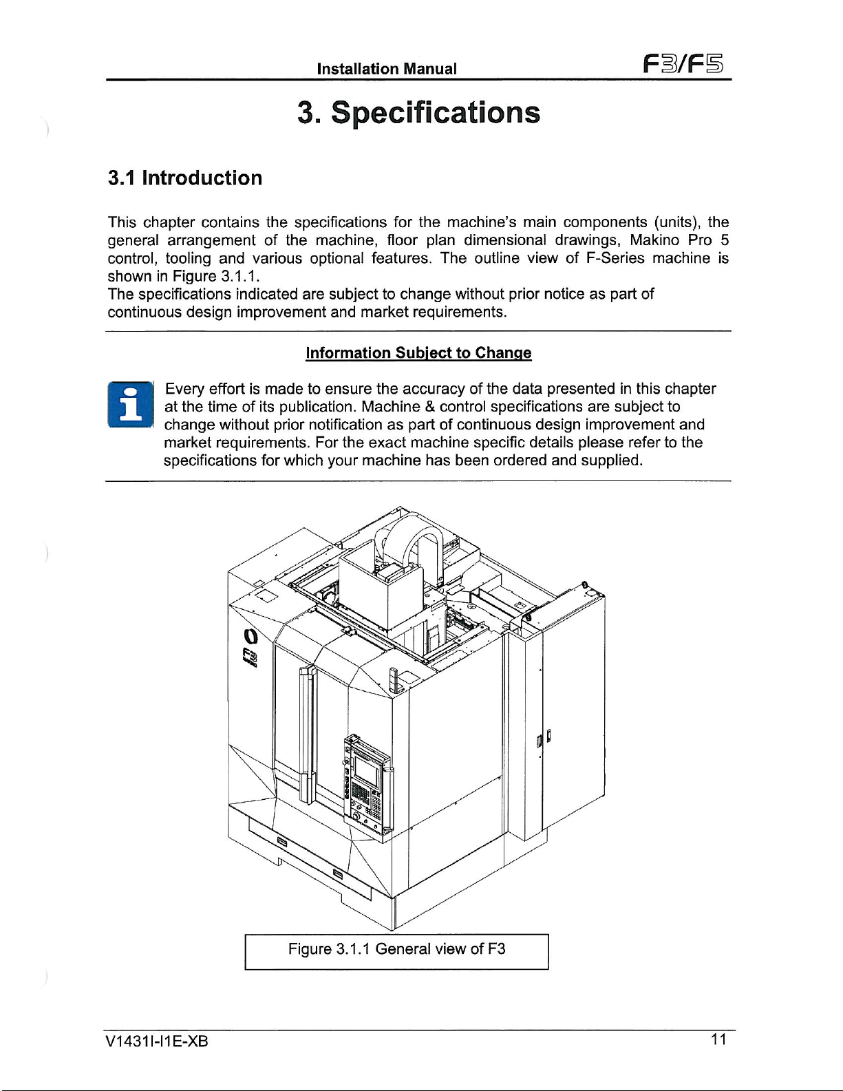
3.1
Introduction
Installation
Specifications
3.
Manual
Fi/FS
chapter
This
general
control,
shown
The
continuous
arrangement
tooling
Figure
in
specifications
Every
at
change
market
specifications
contains
and
3.1.1.
design
effort
the
timeofits
without
requirements.
specifications
the
machine,
the
of
various
indicated
improvement
is
made
for
optional
are
Information
to
publication.
prior
notification
For
which
<>
subject
market
and
ensure
Machine
the
machine
your
for
floor
features.
change
to
requirements.
Subject
accuracy
the
as
part
machine
exact
the
machine’s
plan
The
&
control
of
has
main
dimensional
outline
without
to
continuous
been
prior
Change
the
of
data
specifications
specific
ordered
•ÿ5
components
drawings,
view
of
notice
presented
design
details
and
Makino
F-Series
part
as
are
improvement
please
supplied.
machine
of
this
in
subject
refer
(units),
Pro
chapter
to
and
to
the
the
5
is
O
Jr
Figure
J'
3.1.1
General
view
of
J
F3
1431
V
1-11
E-XB
11
Page 15
3.2
Mechanical
and
Installation
Electrical
Manual
Specification
Fl/F
The
table
MACHINE
Axes
X,Y,Z
(F3)
Axes
X,Y,Z
(F5)
Table
of
Table
of
Load
_
(F3)
(F5)
Size
Pitch
top
face
Hole
Table
Spindle
TABLE
Size
Size
Table
&F5)
Maximum
Table
Maximum
Table
T-Slot
T-Slot
Tapped
below
STROKES
Travel
Travel
Work
_
Work
outlines
to
(F3)
(F5)
Capacity
Size
Size
_
Size
the
brief
650x500x450
900x500x450
150-600
850x500
1000x500
650
(F3
on
850x500x450
on
1000x500x450
18H8
100
M16
general
mm
mm
mm
machine
mmxmm
mmxmm
Kg
mmxmmxmm
mmxmm
mm
mm
specification.
25.59x19.68x17.72
26.77x19.68x17.72
5.9
mm
x
23.63
-
33.46x19.68
39.37x19.68
1433
33.46x19.68
39.37x19.68x17.72
0.70866H8
3.94
in
in
in
x17.72
x
in
in
inxin
Lbs
inxinxin
in
xinx
in
In
In
SPINDLE
Spindle
Spindle
Maximum
Spindle
Spindle
Clamp
Tool
SPINDLE
Spindle
Spindle
Maximum
Spindle
Spindle
Tool
Clamp
Tool
Clamp
V1
431
1-11
HEAD
Speed
Power
Torque
Nose
Cooling
Oil
Force
HEAD
Speed
Power
Torque
Nose
Cooling
Oil
Force
Force
E-XB
12,000
Range
15min/cont
15min/cont
System
20,000
Range
30min/cont
30min/cont
System
(BT40)
(HSK)
RPM
RPM
120-12000
22/18
117/95
MAS
403-BT40
Jacket
8800
Cooling
5%
+
200-20000
15/11
32/19
403-BT40
MAS
A63
Cooling
Core
±
8800
17600
5%
+
5%
(ASPAC)/1
kw
Nm
DIN
/
N
kw
Nm
DIN
/
and
Jacket
N
N
30-1
69871
69871
Cooling
3000
(US)
29.5/24.14
1035.5/840.8
-A40
/
JIS
1978
20.4/14.7
283.2/168.2
-A40
/
JIS
1978
3957
B6339-40T
+
5%
B6339-40T
±5%
5%
+
hp
Lbf-in
Lbf
l
HR
Lbf-in
Lbf
Lbf
RPM
/
HSK-
12
Page 16
Installation
Manual
Fi/F
SPINDLE
Spindle
Spindle
Maximum
Spindle
Spindle
Tool
ATC
HEAD
Speed
Power
Torque
Nose
Oil
Clamp
No.ofTools
Change
Tool
Tool
Max.
Max.
Max.
PNEUMATIC
Min.
Consumption
Diameter
Length
Tool
weight
Tool
Pressure
30,000
Range
15min/cont
Cooling
Force
Time
SUPPLY
RPM
15min/cont
System
5
0.4
300-30000
15/11
20.4/14.6
MSK-F63
Cooling
Core
13600
20/30
1
.3
114/76.2
130
empty)
300
8
±5%
(Option)
(tooltotool)
(with
_
Kg/cm3
M3/min
kw
Nm
Jacket
and
IN
(ATC20/ATF5)
alternate
pocket
Cooling
71
106
20.4/14.7
180.5/129.2
3057
l
+
sec
mm
mm
k£L
5%
Lbs/in2
Gal/min
hp
Lbf-in
Lbf
l
RPM
POWER
200/220
EQUIPMENT
Spindle
Spindle
Spindle
Axis
Axis
Axis
ATC
Spindle
Spindle
Coolant
Coolant
Coolant
Hydraulic
SUPPLY
V
(12K)
(20K)
(30K)
Feed
-
-
Feed
-
Feed
Magazine
Cooler
Cooler
Pump
Pump
Pump
Unit
POWER
Axis
X
Axis
Y
Z
Axis
(12K)
(20K)
-
Nozzle
Through
-
Through
-
|
CHART
coolant
Spindle
Spindle
3
phase,
50/60
Coolant
Coolant
1
3
.5
Mpa
Hz
Mpa
22/18
15/11
15/11
4.2
4.2
4.2
0.5
1.6
3.07
0.925
2.2
3.7
1.5
40
KVA
Kw
KW
KW
Kw
Kw
Kw
Kw
Kw
Kw
Kw
KW
KW
KW
29.5/24
20.1/14.7
20.1/14.7
5.6
5.6
5.6
0.7
2.1
4.1
1.2
3
4.7
2
Hp
HP
HP
HR
HP
HR
HR
Hp
Hp
Hp
HP
HP
HP
V1431I-I1E-XB
13
Page 17
Installation
Manual
Fi/F
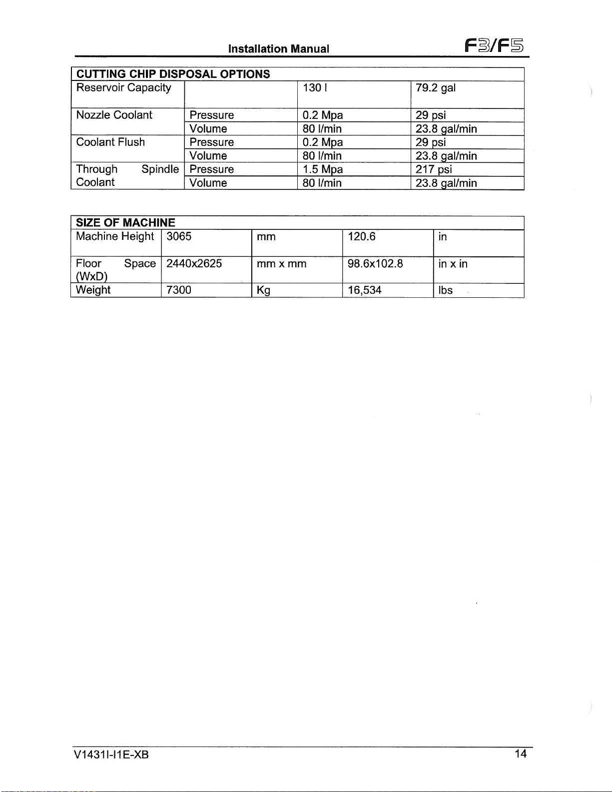
CUTTING
Reservoir
Nozzle
Coolant
Coolant
Flush
Through
Coolant
OF
SIZE
Machine
Floor
(WxD)
Weight
CHIP
DISPOSAL
Capacity
Spindle
MACHINE
Height
Space
Pressure
Volume
Pressure
Volume
Pressure
Volume
3065
2440x2625
7300
OPTIONS
mm
mm
Kg
x
mm
130
0.2
80
0.2
80
1.5
80
I
Mpa
l/min
Mpa
l/min
Mpa
l/min
120.6
98.6x102.8
16,534
79.2
29
23.8
29
23.8
217
23.8
gal
psi
gal/min
psi
gal/min
psi
gal/min
in
inxin
lbs
V1
431
1-11
E-XB
14
Page 18
Installation
Manual
Fi/FE
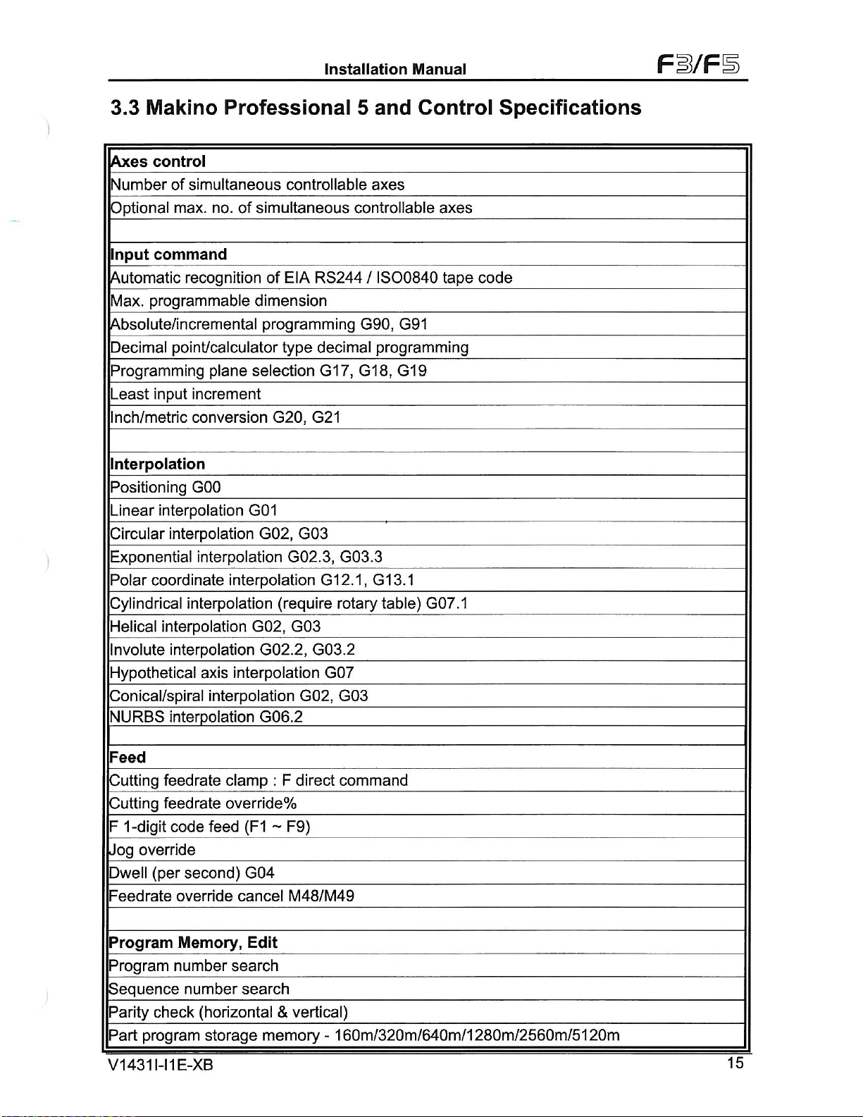
3.3
Makino
control
Axes
Number
Optional
Input
Automatic
Max.
Absolute/incremental
Decimal
Programming
Least
Inch/metric
Interpolation
Positioning
Linear
Circular
Exponential
Polar
Cylindrical
Helical
Involute
Hypothetical
Conical/spiral
NURBS
of
max,
command
programmable
point/calculator
input
interpolation
interpolation
coordinate
interpolation
interpolation
interpolation
Professional
simultaneous
no.
of
recognition
plane
increment
conversion
GOO
interpolation
interpolation
interpolation
interpolation
axis
interpolation
controllable
simultaneous
EIA
of
dimension
programming
selection
G01
G02,
G02,
G02.2,
G06.2
RS244/IS00840
type
decimal
G17,
G20,
G21
G03
G02.3,
G12.1,
(require
G03
G03.2
G07
G02,
5
and
axes
controllable
G90,
programming
G18,
G03.3
G13.1
rotary
G03
table)
Control
G91
G19
G07.1
axes
tape
Specifications
code
Feed
1
-digit
override
(per
check
program
431
1-11
feedrate
feedrate
Cutting
Cutting
F
Jog
Dwell
Feedrate
Program
Program
Sequence
Parity
Part
V1
clamp
override%
code
feed
second)
override
Memory,
number
cancel
search
number
(horizontal&vertical)
storage
:
(F1
~
G04
Edit
search
memory
F
E-XB
direct
command
F9)
M48/M49
160m/320m/640m/1280m/2560m/5120m
-
15
Page 19
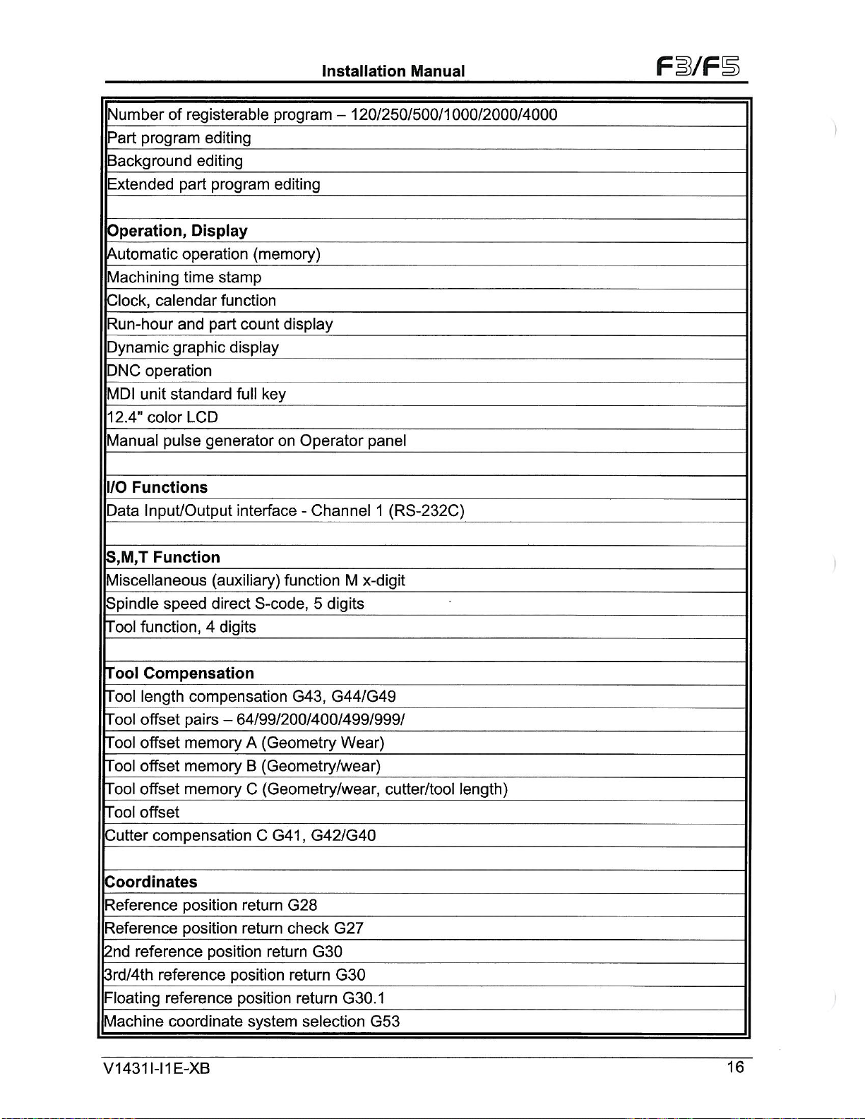
Number
Part
Background
Extended
of
program
part
registerable
editing
editing
program
Installation
program
editing
Manual
120/250/500/1000/2000/4000
-
FB/FB
Operation,
Automatic
Machining
Clock,
Run-hour
Dynamic
operation
PNC
MDI
unit
12.4"
color
Manual
I/O
Functions
Input/Output
Data
S,M,T
Display
operation
time
calendar
and
graphic
standard
LCD
pulse
Function
Miscellaneous
Spindle
Tool
speed
function,
(memory)
stamp
function
count
part
display
key
full
generator
interface
(auxiliary)
direct
4
S-code,
digits
display
Operator
on
Channel
-
function
5
M
digits
panel
(RS-232C)
1
x-digit
Tool
Compensation
Tool
length
Tool
offset
offset
Tool
offset
Tool
Tool
offset
Tool
offset
Cutter
compensation
Coordinates
Reference
Reference
2nd
reference
3rd/4th
Floating
Machine
V1
431
reference
reference
coordinate
E-XB
1-11
compensation
-
pairs
memory
memory
memory
position
position
64/99/200/400/499/999/
(Geometry
A
(Geometry/wear)
B
(Geometry/wear,
C
C
return
return
position
return
position
position
system
G43,
G41
G28
check
return
return
G44/G49
Wear)
,
G42/G40
G27
G30
G30
G30.1
selection
cutter/tool
G53
length)
16
Page 20
Installation
Manual
Fi/FE
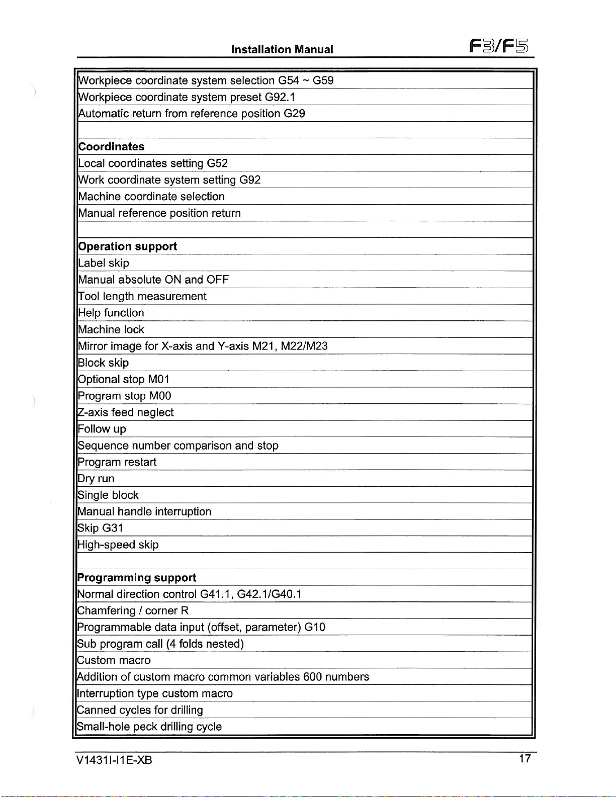
Workpiece
Workpiece
Automatic
Coordinates
Local
Work
Machine
Manual
Operation
Label
Manual
Help
Machine
Mirror
Block
Optional
Program
Z-axis
Follow
Sequence
Program
Dry
Single
Manual
Skip
Tool
run
G31
coordinates
coordinate
coordinate
reference
skip
absolute
length
function
lock
image
skip
stop
stop
feed
up
restart
block
handle
High-speed
coordinate
coordinate
return
from
setting
system
selection
position
support
and
ON
measurement
X-axis
for
M01
MOO
neglect
number
comparison
interruption
skip
system
system
selection
preset
reference
G52
setting
return
OFF
Y-axis
and
position
G92
M21
and
stop
G54-G59
G92.1
G29
,
M22/M23
Programming
Normal
Chamfering
direction
/
corner
Programmable
macro
custom
of
type
cycles
peck
E-XB
call
Sub
program
Custom
Addition
Interruption
Canned
Small-hole
431
V1
1-11
support
control
R
input
data
folds
(4
macro
custom
for
drilling
drilling
G41.1,
(offset,
nested)
common
macro
cycle
G42.1/G40.1
parameter)
variables
G10
600
numbers
17
Page 21
Installation
Manual
Fi/Fl
Circular
Scaling
Coordinate
interpolation
G51/G50
system
Programmable
Rigid
tapping
Programming
G84.2,
Playback
Tapping
Cutting
Exact
Exact
Automatic
Machine
Backlash
Stored
Single
mode
mode
mode
stop
G09
stop
corner
Accuracy
compensation
pitch
error
direction
by
rotation
mirror
support
image
G84.3,
G63
G64
G61
override
Compensation
compensation
positioning
R
programming
G68,
G69
G51.1/G50.1
M135
G60
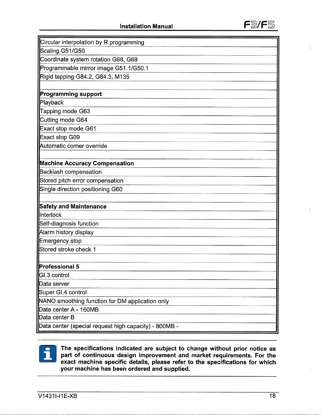
Safety
and
Maintenance
Interlock
Self-diagnosis
Alarm
Emergency
Stored
history
stop
stroke
Professional
GI.3
control
Data
server
Super
NANO
Data
Data
Data
GI.4
control
smoothing
center
center
center
A
B
(special
The
part
exact
your
function
display
check
5
1
function
160MB
-
request
specifications
of
continuous
machine
machine
specific
has
DM
for
high
indicated
design
been
application
capacity)
are
improvement
details,
ordered
only
800MB
-
subject
please
supplied.
and
-
to
and
refer
change
market
the
to
without
requirements.
prior
specifications
notice
For
which
for
as
the
V1431I-I1E-XB
18
Page 22
Installation
Manual
Fl/F
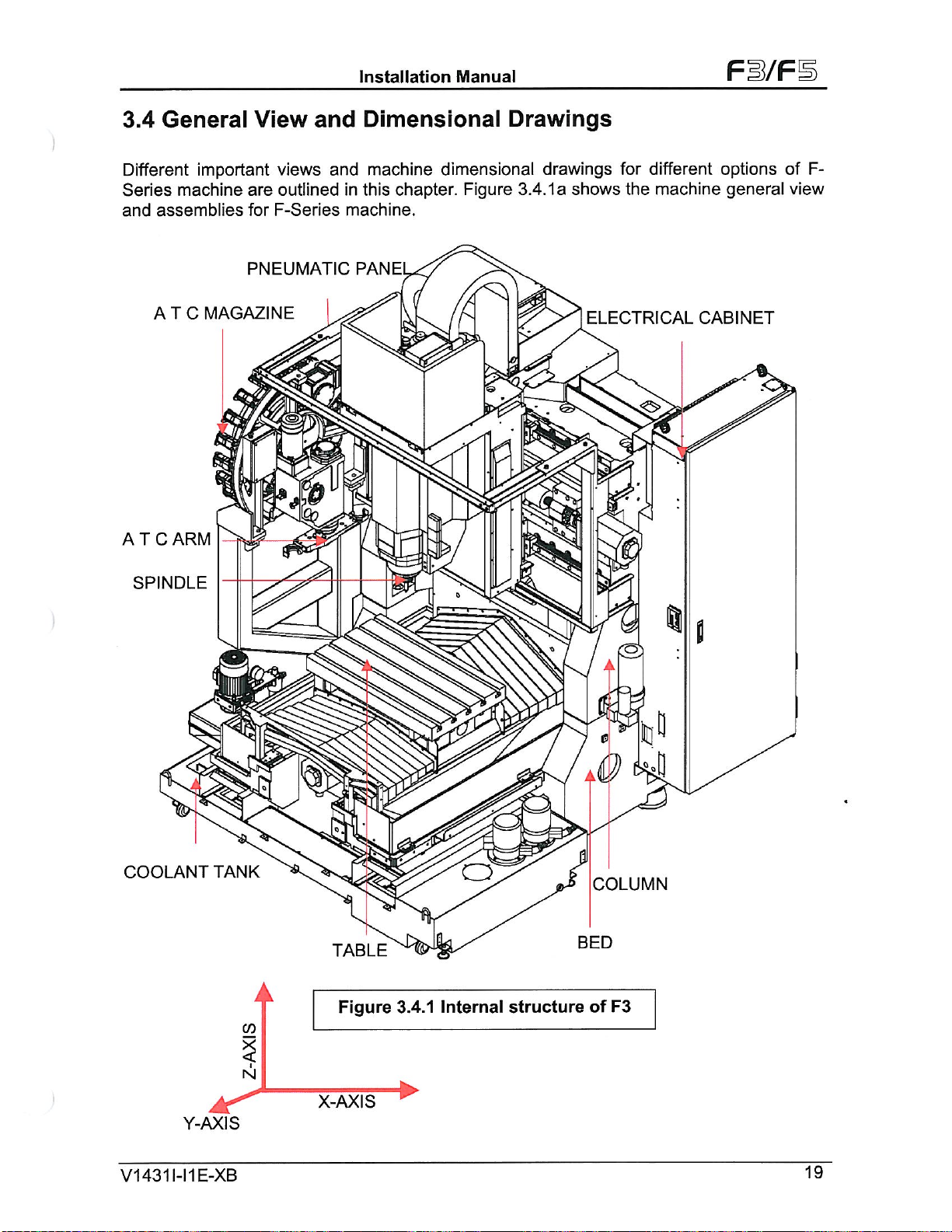
3.4
General
Different
Series
and
AT
machine
assemblies
A
T
ARM
C
important
are
for
PNEUMATIC
MAGAZINE
C
View
views
outlined
F-Series
%
and
and
in
machine.
Dimensional
machine
this
PAN
El
dimensional
chapter.
Figure
Drawings
drawings
3.4.1a
o
shows
ELECTRICAL
for
the
different
machine
CABINET
options
general
of
view
F-
SPINDLE
COOLANT
TANK
co
TABLE
Figure
3.4.1
o
Internal
structure
A
COLUMN
BED
F3
of
&S
V1
431
Y-AXIS
1-11
E-XB
4ÿ
3
N
X-AXIS
19
Page 23
Installation
Manual
Fi/F
—350...
300
j
.
£
•\
/
£5
as
Y
II
i|
I
L-|V/
ib
\
\
I
!
o
o
<>ÿ
s
1
|
g
is?
8:
1
i
I
00
Cn
Is
I
,/
!
4
g
_
Lgsi
rsf
'
I
rj
!
s
i!
1555
855
785
111
o
SP'NDLF
JI!
525
400
m
695
&
/
.
695
I
...135
Lkzÿ
m2
>>
I
I
iro
S
&
..'T\
t
O
650
\
STROKE
'N
:1S\.
.7
325
|
325
i
*‘N_
I
[8
fro
lo
to
2
t
1615
385
I
.
o
T
I
%
705
i
i
I
/,i
>ÿ
:rU
IS
«gsi
.1
?
!!
!
l
\
I
ii
I
*
/:
g
s
*IO
g
.8
3
is
'C=3S-
8
:
Cn
i
V1431
o
1-l
1
E-XB
a
RANGE
Tank)
£
J95
3-
500
i:
!
305
400
20
COOLANT
TANK
OUTSPACE
|L
285 285
305
L.
4I'>
Figure
600
950 950
2510
3120
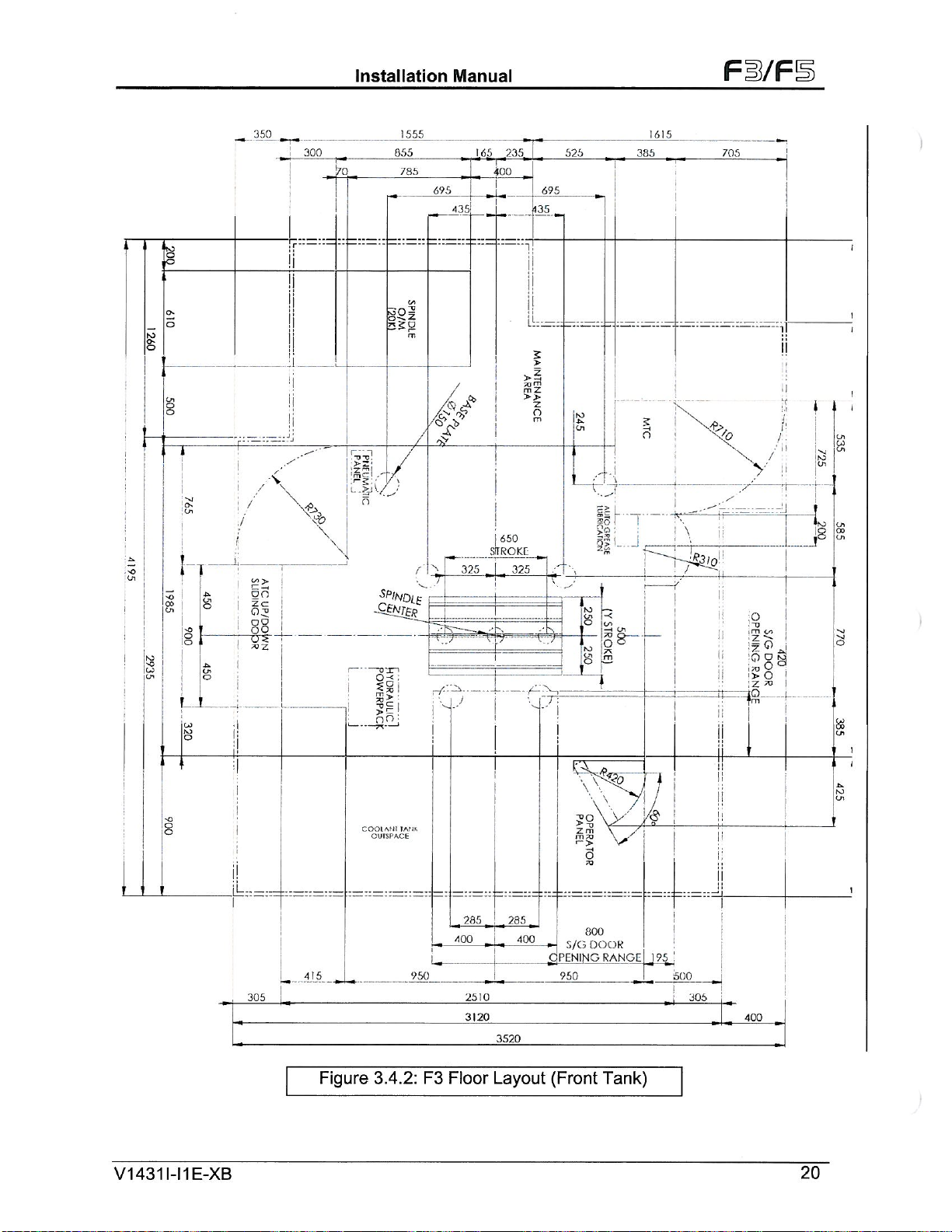
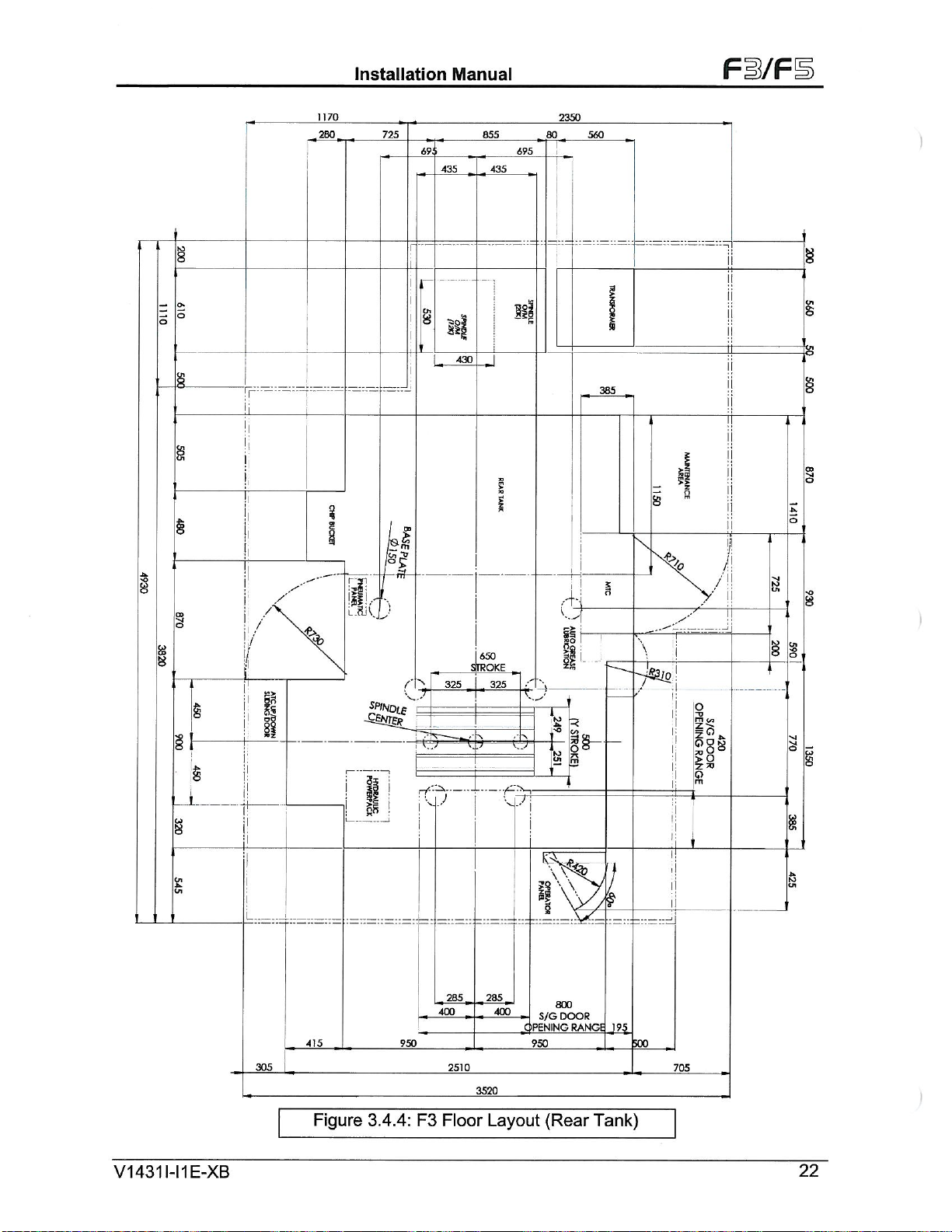
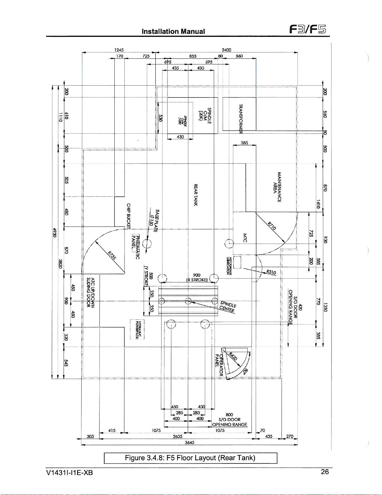
3.4.2:
F3
Floor
400
|
,
3520
Layout
Zm
3
800
5/GDOOR
—
C]PENING
(Front
Page 24
Installation
Manual
§
Fi/F
1
o
O
Fi
u
§8
a
«i;
§
§1
§
*
u
?ÿ
§
O
a
8
I
g
a
E3
65QfX-SfROKE]
2440
WIDTH)
950
195
345
850fTABl:
950
1
14311-11
V
E-XB
550
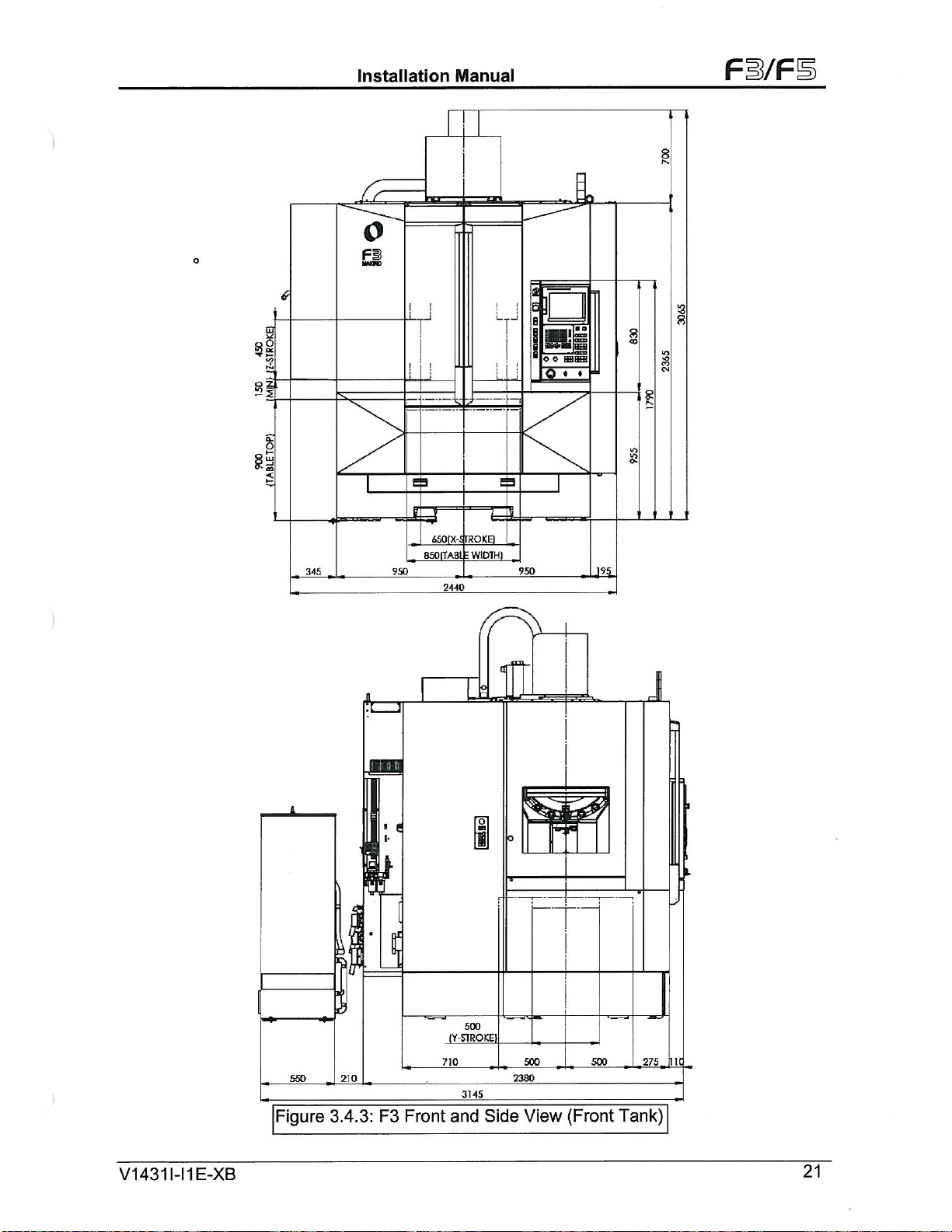
Figure
210
3.4.3:
8
C-
F3
I
Front
500
(Y-STROKE)
710
3145
and
0
Side
500
2380
View
500
(Front
275,
Tank)
I
nc
21
Page 25
Installation
Manual
Fi/F
695
s|
80
K
f*
2350
I
II
5
560
§
i
i
I
i
S
:a
385
I
8
5
5
§
I
TT
I
I
I
I
l
/
T
o
Is
Is
§
I
1
£
o
8
§
3
8
I
1
i
i
g
1170
280
§
CK
s
725
855
69'
435
r
i
435
g
ill
"L_*°
§.
g
i
§
I
I
I
§
8
8
§
8
§
1.
g
/
/
/
8
i
s
ijlj
m
i
I
si
n)
•s
c
SPINDLF
SiNjBR
ii
P
Y=*
l
i
i
'••Jv
325
J
I
I
650
STROKE
325
v7
V
1431
£
Ol
1-11
E-XB
i
L.
285
400 400
3.4.4:
950
F3
2510
Floor
415.
305
Figure
'T
285
3520
Layout
*
.QPENING
l~Y:
800
S/GDOOR
950
(Rear
YA
RANGE
Tank)
J3.
Ij
500.
705
K
22
Page 26
Installation
&
Manual
Fl/F
8
K
150
IMM/i
§i
<S>
ft
F3
ij
Li
;ÿ
§
o
o
M
Li
ii
Et
>
o
%
5
£
J
650
(X-STROKE;)
345
525
850
2440
525
195
lO
•o
a*
s?
00
8
SPINDLE
OILTEMP
CONTROLLER
1110
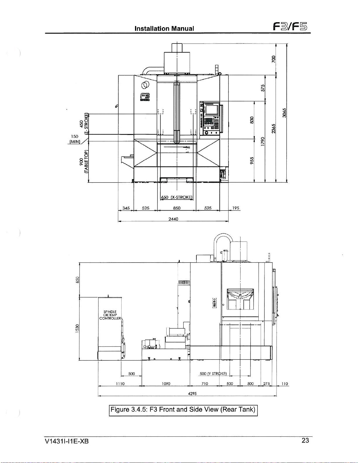
Figure
\
500
3.4.5:
F3
1090
Front
X
and
4295
Side
500
710
View
I
STROKE)
|V
m
•O
500
(Rear
500
Tank)
275
l
110
V1431I-I1E-XB
23
Page 27
Installation
Manual
Fi/F
350
300
70
Tr;:=-~
:§
<>
to
380
855
1680
695
435
290
1
2351
435ÿ
695
525
385
1615
705
s
i
900
STROKE)
!
5
a
I&
X<?
S
\
i
>-S3J0
i
f
:§
g
cn
&
cn
g
/
/
I
!i
0
O
o
v
cPlN°l£
I
#
gs§
I
s
5
§
S
:
\v
/
/
&
H
!*!
L«J
IL
Cn
5
g
§
fO
a
u
8
.
-ii
§
!!
ii
i
r®"i
!
C'
2
S?
rrl
*io
.8
g
__
(
rf
(X
J
V1431
S
1-11
E-XB
I
ii
COOLANT
TANK
305
415
Figure
OUISPACE
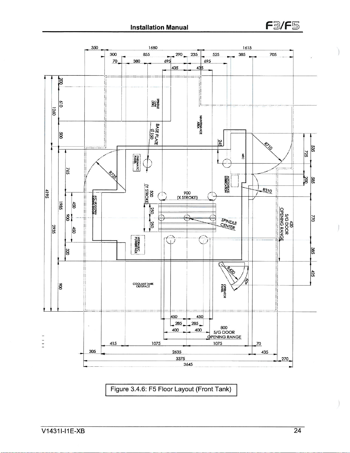
3.4.6:
1075
F5
Floor
450
285
400
2635
3375
Layout
3645
450
285
400
-
OPENING
(Front
1075
1
3
800
DOOR
S/G
Tank)
V7
RANGE
i
I
I
-Z0
435
270
24
a
Page 28
Installation
Manual
Fi/F
3§
Si.
CL
2
fH
I
]
si
2
o
FS
wnc
LJ
LJ
£
Q
ini
.1075
a
o o
Q
EErTTT’
»
<
3
i
s
S
O'
_
j
L
6
!
1075
a
£
1000
900
(XJTROKE)
(TAB-EWIDTH)
2565
I
345_ÿ
/fÿV
JB
-
I
1
T
it
1
sm
X
e
&
____
_
__
_550
.270.1.
1_210
[s]
0
I
______
500
STROKE)
[Y
.710
3145
“0
L
2380
500
J_275
JOS
V1431
1-11
E-XB
Figure
3.4.7:
F5
Front
and
Side
View
(Front
Tank)
25
Page 29
Installation
Manual
Fi/F
695
3
m
-r
l
te
1
I
2400
80
-H
irT"
560
I
8SL..J
is
I
70
>
co
o
m
385
I
I
I
4
I
I
§
c
n
8
§
I
00
>>
S
1
ir—
/
o
II
P>
!
/
s
SO
a
§
§
S
g
\p
-"'rr:
\
!
7-53/0
1245
170
725
855
6?5
435
T
§
Os
:i:.j
8
Sl
l
430
o
r
8
!i
n
?
n
CO
Sj
nt
435
-2520
?s
£
a
CD
8
/
%
sat
3
o
1
|
7-
§8
g£
2
s
!!
of
s
§1
7DZ
§
nisi
CD
a
II
6s
C
2-
g
10
.8
[f*
900
STROKE)
(X
cn
ft
1
305
V1431I-I1E-XB
£5
5
sss
5
o
„2B5_
3645
450
400
Layout
S/G
OPENING
1075
(Rear
450
285
400
415
,
JL,
Figure
1075
3.4.8:
F5
2635
Floor
800
DOOR
£
RANGE
Tank)
-70
435
.270ÿ
26
Page 30
Installation
Manual
Fi/F
§
150
(MINI
lUr-
si.
<
(5)
FS
6
.L.
J
L.J
\M
o
•
g
3
a
s
in
'O
ro
CN
8
3
.Jr-
(X-STROKEI
900
345
575
2555
1000
575
70
2
20
500
710
1
STROKE)
(Y
View
500
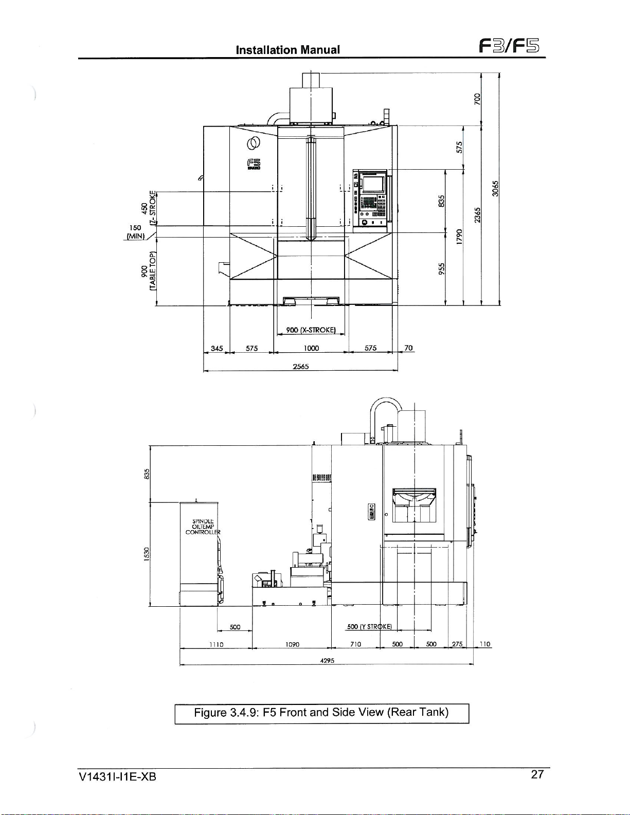
(Rear
500
Tank)
.275.
110
SPINOLfc
OILTEMP
CONTROLL6
8
»o
i
J2
.rfefU
-0
1110
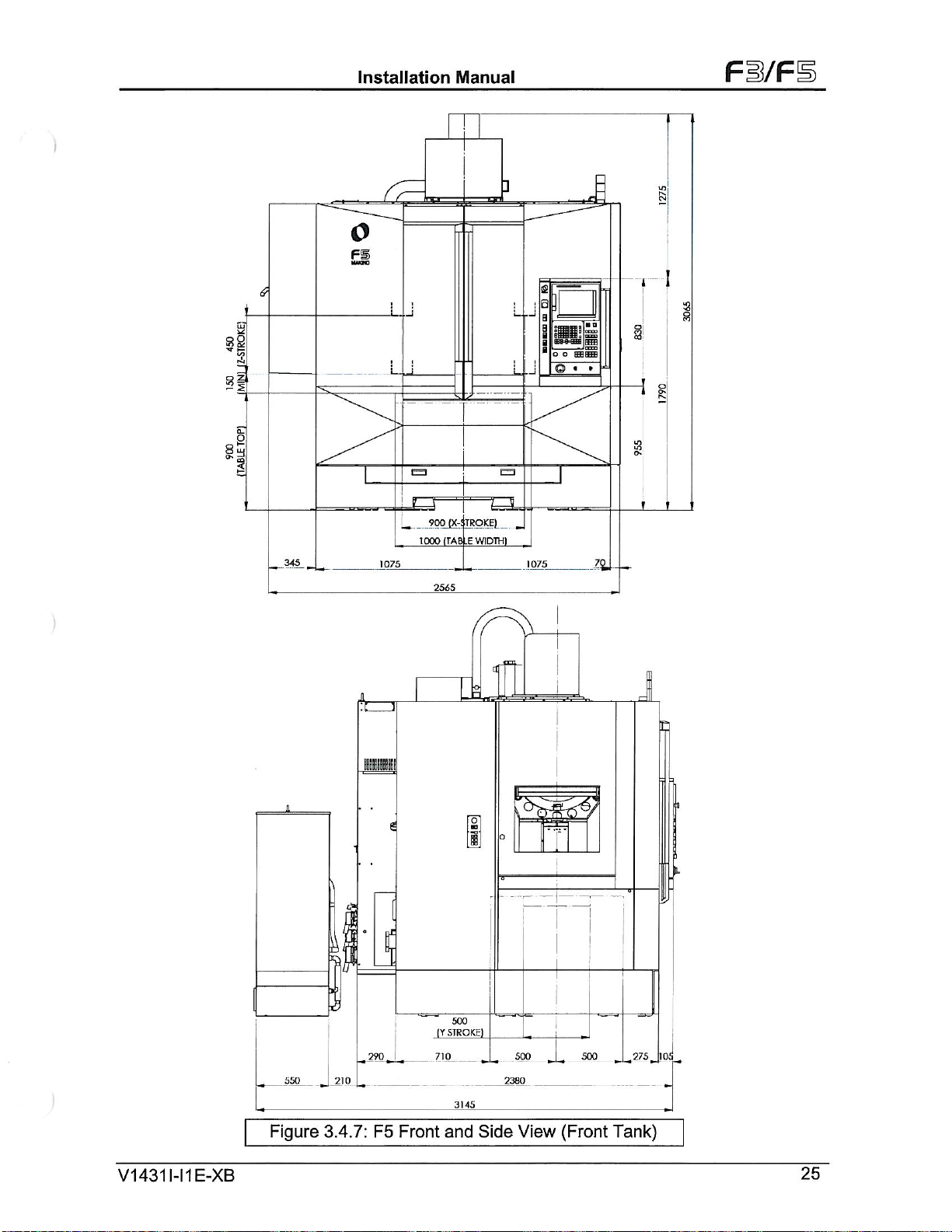
Figure
500
3.4.9:
X
F5
Front
1090
—
5
4295
and
Side
V1
431
E-XB
1-11
27
Page 31

s
I
\
i
j
1
;
i
/
Fi/F
143
120
MAX
560
TOOL
239
DIA
TOOL
CHANGE
3
§
s
EA
Al
Installation
115
C
AT
ARM
e
l
j
••
45
TOOL
CHANGE
18
5
102
r
5
300
410
D
STROKE
LEVEL
Manual
1247
348
4
I
;
f
i
n
/
iso.
517
wm
Si
s
a
g
150
450
(Z-Slroke)
g
<!o
g
I
OJ
£
i
.h
4
dN
i
i
»
\
S
/
•o
View
A
3
K>
8
8
L.
(‘
209
C=
G
G
FRONT
450
600
IPINDLE
CENTER
79
75
500
500
168
§
8
8
t
A
8
b.
fir
ho
S
In
g
8
'O
&
V1431I-I1E-XB
209
BACK
270
370
390
424
20
61
£
Figure
3.4.10:
F3
Work
Area
28
Page 32

Installation
Manual
Fi/F
1247
115
STROKE
ATC
ARM
45
TOOL
CHANGE
LEVEL
NO
©
108
140
V</0
NO
CD
NO
I
/
300
410
\
I
I
t
t
!
I
150j450
(Z-Stroke)
T
f
CD
8
CO
&
o
X
dr
O
7<r
CD
Cn
O
348
NO
NO
o
CO
O
O
i
8
o
250
517
%
m
S
(
V
\
.SPINDLE
LI.
1
CENIER
43
120
MAX
560
TOOL
239
TOOL
CHANGE
DIA
AREA
o
o
©
o
Cn
C
n
o
CO
Cn
o
(X
o
N
CO
i
i
View
A
\
sP
-o
NO
Cn
O
Cn
o
o
NO
Cn
O
s
\
L.
NO
CO
o
n
A
J
v
£
i
'i
209
d
C=
L
*
79
500
75
t
A
FRONI
600
o
,o
450
i
'
pi
7
NO
I
CA3
•On
i
370
-
424
'2Q
.
'T,
NO
I
ivj
<=>
-Vrri
NO
00
00
c*
*—
t
/
-
;
N
\
\
I
V
500
]68
J
t
Cn
O
Cn
s
209
J>\
BACK
270
390
CN
«
0
Figure
3.4.1
F5
Work
1
:
Area
V1431
1-11
E-XB
29
Page 33

Installation
Manual
F3/F1
Tooling
3.5
Preparation
Specification
tooling
of
shouldbeaddressed
fixtures
for
detailed
tooling
machine.
Fixtures
Consider
the
design
machine
for
and
a
underutilizationofthe
Tooling
The
three
cutting
and
highspeed
machining
maximize
When
•
selecting
Tool
holders
exceed
holders
Tool
•
ability,
Never
•
the
Use
•
Select
•
provide
tools
machine
use
important
most
tools
for
spindles
applications
utility,
tooling:
should
the
manufacturer’s
should
balance,
and
Weldon
shortest
the
shortest
better
and
fixtures
before
manufacturing
smooth
the
drawing
transition
machine.
factors
high-speed
have
limitations.
are
within
production,
parts
be
designed
design
designed
be
concentricity.
or
possible
tool
tool
side
life
lock
tool.
holder
and
typically
delivery
specifications
time,
of
and
into
understand
to
machining
Know
spindle’s
the
and
the
for
ratings
high-speed
for
holders
and
surface
at
cutting
finish
require
the
machine.
different
for
co-ordinate
production
and
consider
balance,
are
the
spindle
allowable
machine
highest
for
high
the
tool.
machining.
rpm.
allowed
tool
while
rpm
lead
long
Refer
completion
schedule
concentricity,
design
radial
component
available
reducing
times.
section
options
when
and
load
Look
by
the
radial
These
4.11
available
with
avoid
to
selecting
and
limitations.
and
side
spindle
and
the
on
good
for
part
geometry.
load
on
two
issues
tooling
on
Sseries
the
delivery
unnecessary
tool
holders
rigidity.
Ensuring
thrust,
life.
spindle.
the
tool
Never
holding
spindle.
and
of
All
will
Short
V1
431
E-XB
1-11
30
Page 34

Installation
Manual
Fi/FS
4.1
This
for
clear
installation
installation
The
installation.
machine
tasks:
•
•
•
•
•
Introduction
chapter
delivery
the
expectations
Review
Establishatime-line
Pre-Installation
Selecting
Dimensional
and
Electrical,
Unloading,
Preparing
describes
and
rests,
process.
information
the
The
installation.
machine
clearances.
Service,
moving.
tooling
Pre
4.
installation
installationofthe
responsibilities
and
large
in
Fifteen
items
drawings
and
part
days
and
and
checklist
checkedinthe
the
Use
location
are
requirements
Air
work
Installation
process
F-series
the
on
before
requirements
detailed
schedule
outlines
resources
(access,
provided
holding
“required”
and
High-speed
all
for
participation
delivery
the
related
for
tasks
key
this
in
environment,
in
section
and
connection
devices.
Process
contains
concerned.The
of
to
completion
to
column
guide
3.4
guidelines
Machining
involvement
and
Makino
your
pre-installation.
of
prepare
be
must
accomplish
to
foundation),
and
determine
to
details
to
Center.
success
of
machine
these
for
items.
machine
completed
the
refer
required
prepare
and
customer
customer
It
establishes
efficiency
time
take
delivery
for
an
efficient
pre-installation
section
4.2
floor
of
in
the
to:
and
space
4.2
Key
Total
The
tooling,
considered.
Room
The
considered.
Easy
The
and
path
clearance
crane,
in
easy
machine
Selecting
factors
Required
Required
accessibility
Easy
Manufacturing
Environment
Floor
machine
workpiece
Space
total
floor
Accessibility
machine
all
for
from
forklifts
unnecessary
accessibility
external
selecting
in
floor
total
Room
Space
For
cabinet
the
accommodate
to
Space
Process
machine
for
foot
print
storing
machine
the
space
placement
doors
trucktothe
over-head
and
delays
for
dimensions
the
the
Space
area
and
in
safe
the
must
Machine
machine
working
the
plus
movement,
and
footprint
total
safe
have
panels
and
machine
the
machine
crane.
machine
discharge
and
installation
floor
Location
location
working
total
to
refer
height
sufficient
swing
to
site
that
rigging
Failure
chips
of
plans,
include:
utilities
machine
the
of
room
completely
provides
and
ensure
to
and
and
various
for
required
area
and
also
plan.
floor
in
room
for
which
safe
open.
sufficient
moving
sufficient
additional
used
coolant.
machine
around
for
future
the
access
Remember
width,
equipment
moving
There
cost.
Refer
options.
the
maintenance
machine
around
height,
like
room
should
section
machine
is
located
the
machine
ensure
to
and
the
mobile
could
also
3.4
for
is
a
swing
result
be
for
V1
431
1-11
E-XB
31
Page 35

Installation
Manual
Fi/FS
Manufacturing
Ideally
reduces
Environment
Proper
than
can
machine:
The
•
•
•
•
•
•
•
•
•
•
the
machine
handling
environment
any
others,
cause
•
•
•
•
•
machine
Dust-free,
Ambient
Temperature
Relative
Dust
Freely
Available
inspection
Enough
fully
to
Adequate
dry
A
foundation
appreciable
control,
direct
In
Near
a
In
place
a
Near
a
Near
a
machine
foundation
Temperature
Humidity
Free:
flowing
room
open
supply,
air
Process
should
and
costs
for
Machine
and
ensure
machine,
sunlight.
source
subjecttolarge
source
Working
foundation
machine
heat.
of
of
extreme
sourceofsevere
be
must
with
location
lighted,
well
Fluctuation
0.3mg/m3
air.
floor
and
equipment.
for
cabinet
and
proper
etc.
flat
deflection.
located
expansion
an
should
and
or
less
bench
maintenance
doors.
sized
strong
and
be
placed
improves
accuracy
and
temperature
metallic
vibration,
such
in
meet
the
free
of
1
:
:
1
:
35
space
work.
utilities
enough
closest
communication
are
of
component
dust,
this
an
strip
following
temperature
0
40°
to
C/30
°
to
70%
for
storing
are
to
the
utmost
and
dependability.
variation.
such
may
environment,
to
absorb
C,
optimum
minutesorless
(no
raw
Adequate
available:
support
to
the
process
between
importance.
failures
affect
conditions:
condensation)
of
grinding
as
accuracy
we
the
vibration.
changes.
24±2°
finished
and
space
electrical
the
around
weight
it
supports.
process
These
A
sub-standard
types.
all
machines,
and
recommend
C
work
machine
powers
of
the
This
steps.
two
factors,
environment
Do
NOT
etc.,
alignments.
a
separate
pieces,
supply,
tooling,
and
machine
placement
more
locate
clearance
clean
the
If
the
and
and
without
V1
431
1-11
E-XB
32
Page 36

Installation
Manual
FWFB
4.3
B
A
deflection.
be
appreciable
of
•
•
•
•
•
•
•
•
•
•
Foundation
To
with
void
guaranteed
specifications
reinforced,
continuous,
thumb,
Minimum
soil
(The
Minimum
Foundation
Minimum
recommended
the
foundation
Floor
Level
If
the
maintain
contact
steel
The
Type
of
When
ensure
all
installation
accuracy
the
isolated,
Refer
the
floor
locating
o
o
o
Figure
flat,
deflection.
foundation
ground
below
thickness
should
anti
vibration
that
to
should
does
machine
Makino.
reinforcement
Concrete
the
Consult
Consult
Locate
vibration
machine
alignment.
machine
on
a
for
concrete
4.3.1
and
strong
NOT
Do
must
resistance
concrete
the
of
foundation
extend
Isolation
a
1
9-mm
absorb
be
within
not
meet
level
of
should
machine
structural
a
Makino
the
machine
environment.
provide
to
accuracy
and
portion
reinforced
the
machine.
floor
details
for
enough
place
the
meet
5
of
ton
medium
minimum
a
around
(3/4-inch)
vibration
some
3.2mm/m.
these
alignment.
and
the
steel
grade
be
of
on
an
engineer
for
acceptance
over
enough
and
foundation
of
the
warranty.
concrete
is
the
foundation
on
to
support
machine
following
/
m2
large
or
300mm.
is
300
of
the
expansion
specifications,
If
inside
upper
FC1
for
the
80
floor
load
or
pillar
a
necessary,
If
or
support
performance,
requirements.
Consistent
foundation
foundation
best
drawings.
the
separate
on
specifications:
sized
crushed
beyond
mm
Foundation
strip
special
a
you
concrete
or
of
stipulations
supporting
install
to
considering
are
more.
building,
a
bearing
one
keep
weight
sections
the
is
of
be
should
be
capacity.
on
this
beams
or
the
machine
customers
Failure
accuracy
that
meets
minimize
to
The
concrete
the
of
of
stones
can
machine
mm
100
placed
foundation
more
at
special
a
be
of
sure
to:
arrangement.
provide
to
pillars
level
must
to
comply
can
the
vibration
machine
concrete.
be
used)
boundary.
thick
anditis
the
perimeter
is
0@230
D1
a
under
and
comply
may
only
be
minimum
and
pad
should
without
As
a
rule
also
of
needed
foundation,
minimum
the
maintain
to
V1431I-I1E-XB
33
Page 37

Installation
Manual
Fi/F
\
\
\\
\
V\
150
\.
'V.
\
\
\
//
1300
£05
£/
£60
'/
s:
V
•
,
'
vT
'V
V/y
5
TEEL
*10
PITCH
£70
y/
£fefi
££5>
£05
V
r
r
150
%
/V
%.ss
g
<r
OJ
ij'i
a
\
\
5
s
»
o
LJ
g
£
f.vl
SJ
o
g
I
£
u
6
//
cz>
2
i
Note:
REINFORCING
\
BOTH
/
LE
This
foundation
These
For
The
data
the
concrete
Symbol
Machine
HORIZONTAL
ING
VELL
are
rubbles,
shows
‘a’
weight,
615
STEEL
1
CONCRE
is
given,
medium
more
standard
/
:
/
Figure
an
than
the
010
VERTICAL''
AND
/
TE
4.3.1:
example
assuming
or
large
180
FC
Machine
7500
570
l
/
REINFORCING
FoundationF3and
of
reinforced
that
allowable
sized
should
Support
kg.
concrete
crushed
be
used.
points.
i
615
/
RUBBLES
bearing
stones
CONCRETE
l
F5
thickness
capacity
should
\\\\
/
LEVELLING
1L
?Rr
/
300mm.
soil
of
be
used.
is
POINT
|!
5ft/sq
m.
V1431I-I1E-XB
34
Page 38

Installation
Manual
FB/FB
4.4
Floor
machine
on
applicable
Markings
intended
Clear
problems
space
Clean
Floor
plan
the
marking
around
the
floor,
units
requirements
considered
4.5
A
less
Power
3-phase
and
a
•
and
Table
•
•
cannot
Stabilizer
Plan
F3
for
to
for
in
floor
before
and
and
locationofthe
the
machine
gangway,
the
the
of
locating
the
machine.
area
marking.
Supply
power
125A
Provide
Ensure
Install
be
source,
breaker
a
4.6.1
the
an
maintained
in
case
and
F5
machine
its
accessories.
ordered,
near
layout
plan
other
completely
Use
and
with
must
properly
assist
to
electrical
additional
within
used
based
Marking
given
is
After
basic
machine,
and
locations
the
machine
helps
intended
before
a
bright
Cables
provided.
electrical
service
±10%.
on
the
voltage
the
stable
be
sized
sizing
in
automatic
in
Section
completion
the
per
placing
are
machine
in
paint
regulation
the
alsotobe
or
as
for
necessary
marking,
The
service
machine
voltages
voltage
(Customer
type
and
3.4
describes
of
transformer,
layout
the
foundation
the
given.
work
done
and
piece,
before
installation
units
around
make
and
marker
customer
(±10%),
box
to
must:
for
electrical
requirements.
all
meet
regulator/Stabilizer
should
plan
dimensions
the
sure
that
mark
a
the
machine.
service.
for
of
the
the
the
location
work,
other
optional
toolings,
locating
and
avoids
machine
factors
all
location.
ground
of
Use
if
required
the
the
locationofthe
unit).
various
of
clearly
the
unnecessary
and
are
25
ohms
local
mark
units
and
other
machine.
moving
or
Code
voltage
as
Table
machine.
Length
machine
the
4.5.1
S/N
Main
gives
Main
(Customer
Wire
Wire
Connecting
the
of
layout
circuit
the
total
power
Description
Breaker/lsolator
Plant
Cable
Type
Size
Size
and
Terminal
cable
istobe
Contact
breaker
Makino
and
Side)
Type
decided
Customer
cables
supply,
125A
100A
XLPE
by
for
the
the
cable
for
for
AWG300MCM
size
230/346
415/440/460
insulated
Copper
mm2
25
M8
the
customer
support
machine.
for
and
Data
VAC
(UL1505,
wire)
/
based
any
clarifications
type
Input
VAC
SWG
on
required
Input
for
Flame-retardant
_
main
supply
before
F3
and
point
installing
F5
and
V1431I-I1E-XB
35
Page 39

Installation
Manual
Fi/F
4.6
F3
servo
If
rating
Table
the
and
Table
Transformer
andF5machine
control
incoming
the
kVA
40
4.6.1
machine
power
its
4.6.1
and
other
voltage
required
is
gives
the
are
available
source.
Regional
Asia
Other
(Option)
requiresaninput
units.
is
types
wise
Region
Pacific
U.S.
Europe
Than
with
as
main
Above
than
other
the
transformers
of
option
an
transformer
voltage
200V,
secondary
along
200V,
of
AC,
30
output
with
suitably
with
incoming
being
the
AC,
30
an
additional
200
rated
machine
voltage
50/60
V.
cables
according
specification.
Transformer
Primary:380/400/420/440V
Secondary:
Primary:
Secondary:
Primary:
Secondary:
Primary:
Secondary:
200V
400/460/480V
200V
380/400/420/440V
200V
220/230/240V
200V
Hz,
for
external
from
to
Voltage
the
main
transformer
transformer
the
countries
of
to
Table
4.6.2
gives
installationofthe
Table
4.6.2
Main
Description
Primary
Secondary
Voltage
voltage
Phase
Frequency
Rating
Voltage
Sec.
Class
Regulation
Type
Winding
Out
put
tolerance
Tapings
the
specification
machine
unless
transformer
required
the
of
ordered
Specifications
the
with
Specification
According
200
03
50/60Hz+/-
40
kVA
±5%
Class
±3%
transformer
machine.
the
to
VAC
1%
H
Isolation
Copper
200V
Winding
and
and
Local
220V
should
Power
be
ready
supply
before
V1431I-I1E-XB
36
Page 40

Installation
Manual
Fl/FS
4.7
•
•
•
•
•
Contact
the
4.8
Table
dryer
the
3.4
A
Earthing/Grounding
Makino
All
Proper
not
Do
Prepare
properly
Ground
Grounding
Air
4.8.1
is
machine
proper
for
valve
pressure
supply
main
connecting
a
with
free
other
cause
machine
grounding
use
a
separate
inspect
100
of
any
certified
Supply
gives
ordered
should
air
opening
for
gauge
valve.
particles,
Machining
requires
the
common
earth
before
ohms
electrician/Makino
preparation
details
the
the
with
near
be
inlet
location.
and
a
Air
port
as
filter
supply
of
they
and
component
Centers
isolated
an
earth
usedinthe
in
pit
connecting
resistance
before
required
of
machine
the
to
The
closing
regulator
PT1/2.
failure.
piping
will
the
Keep
damage
Preparations
be
earth
to
the
less,
Customer
incoming
is
supply
supply
air
0.005mm
with
drop
the
the
properly
ground
plant.
with
machine
is
required
the
machine
available
air
inlet.
line
from
line
Air
line
must
accordance
or
installing
which
machine
air
grounded
local
support
supply
air
as
Refer
should
required
is
of
the
top
and
filters
at
the
for
machine.
regulations
for
specification
option.
an
the
have
at
filtration
the
of
of
the
clean
air
pipes
the
time
near
any
clarifications
The
air
foundation
permanent
supply
the
are
recommended
main
lineisrecommended
and
drier
and
installation.
of
the
machine
unless
supply
layout
piping.
point.
free
from
the
regarding
an
air
to
point
section
main
A
after
dust
machine
and
air
the
and
or
Table
4.8.1
Description
•
Supply
Inlet
Ambient
Relative
Machine
Consumption
Filtration
Air
Connection
Inner
Quality
Air
Air
Humidity
Pressure
Dryer
of
Dia
Pressure
Required
Incoming
Makino
air
air
Supply
Air
Temperature
Specification:
Temperature
(Volume)
Port
Hose
Air
considers
supply
must
to
not
Supply
it
machining
the
exceed
0.5to0.8
5°
to
5°to40°
Less
0.5
400
Water
Refrigerated
PT1/2
Over
ISQ8573-1
customer’s
the
relative
40%
35°
than
MPa
min.
L/
Female
15mm
center
Specification
MPa
C
C
%
40
m3/min)
(1.52
Trap
and
Membrane
or
016mm
ISQ1.5.1
,
responsibility
is
both
clean
humidity.
Oil
Mist
Type
to
and
Filter
Hose
ensure
dry.
with
(Option)
Nipple
that
Supplied
5p
and
(Machine
the
0.3p
filter
Side)
Please
Note:Ifthe
recommended
V1
431
1-11
E-XB
to
use
incoming
Air
an
air
Drier
is
not
just
good
before
cannot
and
connecting
meet
the
the
Main
minimum
Air
supply.
standards,
it
is
37
Page 41

Installation
Manual
F3/FS
4.9
•
•
•
•
•
•
•
•
•
•
•
•
4.10
During
installing
•
•
•
•
•
•
•
•
•
•
•
•
•
•
Machine
F3
machine
Professional
and
installing
Overhead
Min
Min
Shop
Mobile
Forklifts
Hydraulic
Eyebolts
shackles
D
Crowbars
Lifting
Service
Cotton
Soft
Cleaning
Cleaning
Big
size
Industrial
Hand
Helmets
Safety
First
Set
of
Dust
Temporary
Aluminum
moving.
the
gap
from
gap
from
floor
Crane
capacity
Jacks,
slings
the
installation
the
machine.
cloth
tissue
brushes
agents
clean
Vacuum
lights
for
Hand
aid
Kit
Tool
Bins
for
Handling
installation
riggers
Following
machine.
Crane
entry
of
the
the
door
capacity
or
wire
Facilities
type
papers
like
cardboards
or
Torch
FSE
gloves
Kit
waste
power
Ladder
only
minimum
Crane
Crane
width
rope
of
Customer
waste
of
different
CTC
cleaner
lights
disposals
facilities
height
of
Facilities
requires
should
facilities
capacity
Hook
to
Hook
to
should
various
of
F3
machine
is
(Never
sizes
/
Acetone
and
6to8
lifting
handle
the
at
the
top
should
floor
be
more
:
T
0
1
10
:
T
5
:
T
(Toe
:
M6, M8,
:
Different
2.5
to
:
lengths
following
requested
use
thread
Heptane
/
Plastic
ft
and
the
customer
10
T
of
the
or
above
or
above
type
M12,
sizes
m
3
to
type
sheets
moving
machine
or
above.
machine
be
about
than
2800mm
preferable)
M16
length
in
facilities
arrange
cloth
Gasoline,
/
of
some
for
unloading,
place
etc
waste)
is
should
3000mm
min
minimum
are
for
machine
soap
heavy
very
be
of
6
2
very
oil
numbers
units.
unpacking,
much
about
nos
installation
500mm
each
much
etc.,
Trained
lifting
essential
essential
and
for
for
4.11
Consider
table
diameter
Specifications,
Consider
that
V1431I-I1E-XB
Toolings
the
below
weight
the
istobe
specification
to
machine
installed.
and
select
Fixtures.
and
the
length
maximum
Prepare
Fixtures
the
of
correct
machine
tooling
please
workpiece
the
fixtures
spindle
specification
refer
Figure
area
accordingly
which
4-11-9
that
that
can
refer
is
be
to
installed.
be
can
Tool
be
accommodated
chapter
used.
Diameter
3
for
Please
For
tool
weight
for
details.
refer
maximum
and
Length
the
machine
the
38
Page 42

Installation
Manual
FI/F
TOOL
TOOL
MAS403-BT40
JIS
SHANK
SHANK
B6339-40T
PULL
AND
TYPE
PULL-STUD
(Retention
Without
Without
With
Without
STUD
Hole
Hole
Knob)
Hole
Hole
DETAILS
12K/13K
FOR
DIMENSIONS
Figure
Figure
4-11-2
SPINDLE
4-1
1-1
TSA/TSC
NOT
APPLICABLE
NOT
APPLICABLE
TSA/TSC
NOT
APPLICABLE
69871
DIN
V-CAT
HSK-A63
-
-A40
No.
40
Hole
With
Without
Hole
With
APPLICABLE
NOT
Hole
Figure
Figure
4-11-3
4-11-4
TSA/TSC
APPLICABLE
NOT
TSA/TSC
V1431I-I1E-XB
39
Page 43

Installation
Manual
Fi/F
TOOL
MAS403-BT40
(JIS
DIN
SHANK
B6339-40T)
69871
-A40
TOOL
TYPE
PULL-STUD
(Retention
Without
With
Without
With
Without
SHANK
Hole
Hole
Hole
Hole
Hole
Knob)
AND
20K
PULL
SPINDLE
STUD
DIMENSIONS
Figure
Figure
DETAILS
4-11-5
1-6
4-1
TSA/TSC
TSA
TSA
V-CAT
HSK-A63
-
No.
40
Hole
With
NOT
APPLICABLE
Figure
Figure
4-11-7
4-11-8
TSA
TSA
/TSC
V1
431
1-11
E-XB
40
Page 44

TOOL
SHANK
Installation
TOOL
TYPE
PULL-STUD
(Retention
SHANK
Knob)
AND
30K
Manual
PULL
SPINDLE
STUD
DIMENSIONS
Fi/F
DETAILS
TSA/TSC
HSK-A63
APPLICABLE
NOT
Figure
4-11-9
TSA
ITSC
V1431I-I1E-XB
41
Page 45

|©1
0.025
Installation
25
11
10
&
S
3
ol
CO
3
I
A
A
1
H
16.6
PS)
(MAS
Shank
Tool
to.-
MAS
CTO
Vi-
403-8T
to.4
2
65,4
t0
92.4
Taper
3
30
39.3
2
Manual
7/24
::aii
V
5
8_
H-Ll
-0.2
22.6
O.OI5/IOOTA1
45.2
22.6
0.2
Fi/F
+0.18
o
16.1
5
0.12
A
-o
CN
.s
•h
E
Cv
0
Pull
Material:
Hardened
Case
Heat
Surface
C2
co
-&
Stud,
Without
SNCM420
to
Depth:
Treatment:
Treatment:
Figure
0.01
UI
o
Hole
58-62HRC
0.5-0.8
HC-Q-T
SOB
4.1
A
I
B
20
25
(MAS403
1.1
±
MAS
A
SL
5
P40T-1)
\±
6
60
Cl
28
403
35
2l
-0.1
c
-0.1
BT
|@|
R0.5
0.01
40
[
A
1
--
t
Vp
4
3
7
Shank
?[0i
2
3?
and
£
®
f
Detail
Scale:
<o
g
ci
P
A
(5
:
1)
Pull
[>
Stud
19-0
-t-
8
0
35
V1
431
1-11
E-XB
42
Page 46

Installation
25
21
10
Manual
Fi/F
9ÿ
,r>
t
©
Taper
7/24
|©1
0
025
6.3S/
WV
A
1
6.3S
©
0
Pull
Material:
Hardened
Heat
Surface
"a
r-'.
©
<>
-o
u-i
P
Tool
5
Case
G
-
2
o
-S
®
*r>
o
•ÿ>
•n
to
©
-v
©
Shank
G
5
Cl.
A//
Stud,
Without
SNCM420
to
Depth:
Treatment:
Treatment:
Cl
5
1
6.6
J>Xr
BT40,
JIS
B
18
I/I
Hole
58-62HRC
0.5*0.
8
HC-Q-T
SOB
B
2
to.
\
ora
6339-40T
O
C0.5
3
|
0.01
25
(JIS
B6339-40P)
-’-C
CO
5
-<J-
HAJ
4
to
92.4
8
*d
7
A
I
O
8
65.4
U
7
54
0
-o.io
)
5
i:
M
2ÿ;
to?
j
<3
m
Cl
23
43
,5
-o.io
29
39
Cl
V
3
30
V*-
0
a
IO
AzsX
6
•«
©
S
1
0.02
-17
1
iiT0.020/100lA|
O
<9
/
-h.
-o
1/1
—
CO
©
O
CO
&
>_Z
7
1
©
|A|
O
od
=>?
©
0.01
Detail
Jo/
¥rÿr
/
7
od
9
O'
©
2
©
0
22.6
G
3.2S
G
S
o
©
ro
CN
©
A|
I
*-0.25
%
0
2.4
V
<a?/
A
G
3.2S/
G
W
v
W
2
8
od
oo
O'
8
© ©
0
-0.2
-0.2
22.6
45.2
0
1
0
6.3S/
L©5
•0
18
16.1
-=-|
3
o
|
0.12
A
1
A
7
fl
o
9
-0.35
G
rv
©
V1431
1-11
E-XB
&
Pull
Material:
Hardened
Case
Heat
Surface
0.5X2
Placesÿ
Stud,
With
SNCM420
to
Depth:
Treatment:
Treatment:
Hole
58-62HRC
0.5-0.8
HC-Q-T
SOB
Figure
18
1/1
0.01
25
4.1
-0.35
©
a
0
g
+0.25
o
SL
and
£
°w
>o
I
7
Pull
19
2
I
©
Stud
I
Detail
A
Shank
A~|
2.4
-o.io
\o»
0
3
40T
H/|0-01
3
0
3.
1
1
5
0
7
-o.io
7
o
54
JIS
23-0.10
29
B6339
[
A
.2
43
Page 47

s
CO
-o
©
Tool
6.3S
£
G-
A
Pull
Material:
Hardened
Case
Heat
Surface
U5
CN
«o
s
Shank
G
2
2
C1.5
Stud.
Depth:
Treatment:
15.9
(#40)
DIN
0.02
/
r--
-
cor
fc>
#40
Without
SNCM420
58-62HRC
to
0.5-0.8
HC-Q-T
Treatment:
Installation
•9
5
A
3.2
69871
-A40
-i
A
B
<S°
3
20
28
Hole
SOB
YA
68.4
87.5
/
«OA7
8
54
(DIN
CN
5
m
32
42.5
±0-2
0.02
A
A
w
/
4
20*0.10
26
69872-19)
r
O
to.io
Manual
Taper
7/24
R1
CO
X
£
s
£
x
6
Fi/F
o
s
22.8
25
47.8
*0*
4*
G
,2K/~
w
a
od
oo
o o
o
N-
CO
— —
s.
•©
\
\
£
+0.25
o
2.4
t
©
2
CO
Cl
<£»
Detail
3.2s
8
5.4
0
o
8
A
•o
=-|
|
A
0.12
7
o
19
-0.35
G
1
V1431I-I1E-XB
6;3$/
Wv
o
CN
D)
2
e
0
0.5x2
Pull
Material:
Hardened
Case
Heat
Surface
|
G
Cl
S3
Places
Stud,
With
SNCM420
to
Depth:
Treatment:
Treatment:
Figure
0.02
/
1
T
_
\
—•©—
Hole
58-62HRC
0.5-0.8
HOQ-T
|A|
B
l"/
N
CO
20
SOB
4.1
—
*s°
1|
0.02
A
/
1
A
ts°0’
R0..
7
6.3
4
20
8
54
69871-A40
DIN
N&_
V
S
±o.)
26
\,
7
to.i
“1
3
28
.3
1
VV
as
.
2
6
CO
G
G
3.2S
Cl
&
Detail
A
Shank
*o5
o
od
pS
-<r
O'
a
G
©-
8
5.4
+0.25
2.4
?§*£<
>
>
wv
\
O
8
<>
and
o
\7W
O'
Pull
•o
D1
©.
G
0
19
-0.35
Stud
44
Page 48

3
*o
CO
G
Tool
0
u
z
3
S-
CO
co
Pull
Materia).
Hardened
Case
Heat
Surface
A
u
z
O'
3
£
CO
ui
*o
CO
Shank
Cl
CO
Stud,
Depth:
Treatment:
Treatment:
vw
®
Stud,
Pull
Material:
Hardened
Case
Heat
Surface
60°
9.195
7
0
15.875
19.05
(#40)
V-CAT
B
r
O
/
Without
Hole
SNCM420
to
58-62HRC
0.5-0.8
HC-Q-T
Cl
C0.5
0
With
SNCM420
to
58-62HRC
Depth:
0.5-0.
Treatment:
Treatment:
7
3.195
0.01
21.85
SOB
B
Hole
HC-Q-T
Installation
A
68.25
87.3
O
CO
“1
Cl
<
*/
5.5
A
O
0.01
A
/
21.85
8
SOB
5
7
48
£
CO
Cl
<*7
5.5
u
z
3
co
CO
4.78
28.45
20.15
u
48
&
Cl
-o
$
,G
-o.io
26.15
5
7
20.15
Taper
3.5"/fool
U-l
O
«
*lT
*°
\0»
o
o
-0.10
Cl
y
V
w
GT
O
-o.i
26.15-0.1
Manual
R1
C?
S
'O
«
z
s
vd
©
0.015/100
i?/
V/
7
So’
3
3
O
ft
tytfAZTr-
-v///
_xZ
K
-o
o
3
o
IAI
o
“1
3
b
55
6.3S
b
od
'}ÿ
© ©
0.01
/
/
/
12.5S
w
Ob
O'
o
o
©
0.01
G
a
©
A
~w
ob
G
/
3.2S
O'
•s
A
0
Ob
G
6"/
0.381
25.019
G
CO
CN
1
6
dowel
dp
Z?
47.625
£
B
22.606
19
0
-0.35
2
e
9
1
o
-0.35
Fi/F
8
WO-12|A|
8
3
V1431
1-11
E-XB
Figure
4.1
1
.4
V-CAT
NO
40
Shank
and
Pull
Stud
45
Page 49

Installation
Manual
Fi/F
|©1
0.025
'
O
A
1
H
•o
C
E
r©.
e_
0
Pull
Material:
Hardened
Case
Heat
Surface
o§
n
u
<r>
©
-o
©
Tool
Shank
CN
CO
0
©
Stud,
Depth:
Treatment:
i
(MAS
l_Ll
C2
Without
SNCM420
58-62HRC
to
0.5-0.
Treatment:
t>
25
21
10
16.6*0,
PS)
o.oi
Hole
HC-Q-T
MAS
8
SOB
*2
8
©
2
\
ac
403-BT
1a
B
20
25
(MAS403
&
n
HH
Li
A
92.4
&
65.4
A
J.
P40T-1)
SL
V?.
±0-2
Li
A
60
39.3
30
Cl
3.
28
Toper
1
A
-o.i
35
.
7/24
TTl
ii
1@1
R0.5
0
-0.1
-LLI
0.01
£
2
®
I
0.015/iQQ
|
A
3
1
7
[71
o
22.6
&
m
ci
Detail
Scale:
*C
13
Q
16.1
2
I
I
A
0.1
'
o
22.6
-0.2
-0.2
45.2
co
CM
©
t-
£
1
3
o
9
-0.35
P
A
(5:1)
.5
E
Cv
0
V1431I-I1E-XB
CN
14
Pull
Stud,
Material:
Hardened
Case
Depth:
Heat
Treatment:
Surface
Figure
00.01
1
B
1
0
C2.
aHI
b
0.5
20
Hole
With
SNCM420
58-62HRC
to
0.5-0.8
HC-Q-T
T
reatment:
SOB
4.1
A
Ool
25
1
Li
.5
A
JSZ.
Li
5
6
MAS
60
[@|0.01
ci
R0.5
/~&~h
w
0
28
-o.i
o
35
-o.i
403
BT
[A
XV
3
40
1%
4
7_
Shank
olo
2
ft
5
*20
0r
Scale:
and
8
•s
Cl
Detail
Pull
R0
P
A
(5:1)
Stud
0
3
0
19
-0.35
46
Page 50

3
Si
Tool
u-)
CN
o
U1
s.
Shank
IN
x2
Si
0
Slue),
Pu
l
Material:
Hardened
Depth.
Case
i
Heat
reatment:
Surface
15.9
(#40)
DIN
!J
vT/
Without
SNCM420
53-C2HRC
to
0.5-0.
Treatment
0
5
-Si
3.2
69871
o.oi
I
Hole
9
HC-Q-T
A
B
21
SOB
87.5
-A40
A
I
-55
!
X
Installation
CN
'ÿo
i
32
42.5
68.4
to
2
—
-
'£
>
kolo.oriAK
0/
/
/
.
u
_
UriA
il-5
25.15
32.15
54
Taper
8
I
TO
Manual
7/24
o
o
!
s
1
._3U
>
o.i
TT
oi
Fi/F
3
-s-|
|
A
0.12
1
22.8
25
47.8
\fr.
£
7
V
-
ro
04
3
*.
\
*©
!
0
o
A
V1
431
1-11
CN
o
5
E
E-XB
-©•
CO
0
Stud,
Pull
Material:
Hardened
Depth:
Case
Heat
Treatment:
Surface
l-i-l
P/
P<7o
o
0.5
With
SNCM420
58-62HRC
to
0.5-0.8
Treatment:
Figure
0-01
Hole
HC-Q-T
B
21.85
SOB
4.1
I
A
\
5£
1
-
1
.6:
&
-
6>
3-15
25.15-0.1
54
DIN
|©|o.oi
[A
o5
2
XL
o
-0.15
32.15-0.1
z
W
3
0
J
7
o
69871-A40
o
X
__
_
Shank
ft
o
CO
°
CN
•o
0
0
Pull
and
19
Stud
m
o
0.35
47
Page 51

=1
3
©
Fi/F
U-)
OJ
8
•ÿd
NO-12|A|
Taper
3.57foot
R1
z
Manual
3?
~
CN
GO
2
dowel
0
6716
0.381
dp
b
'O
0ZZZ2i
Installation
60°
9.195
7
u-)
t
©
CO
'C
€>
©
o
2
CO
lO
7/
A
Tool
Shank
u-
z
co
=3
co
io
A
Stud,
Pull
Material:
Hardened
Depth:
Case
Treatment:
Heat
Surface
u
z
CO
3
0
S°
CO
0
Stud,
Pull
Material:
Hardened
Case
Depth:
Heat
Treatment:
Surface
15.875
19.05
(#40)
L
p/
>
Without
SNCM420
58-62HRC
to
0.5-0.8
HC-Q-T
Treatment:
_L
P/
0.5
Hole
With
SNCM420
to
58-62HRC
0.5-0.8
Treatment:
V-CAT
o.oi
B
21.85
Hole
SOB
0.01
B
21.85
HC-Q-T
SOB
3.195
A
O
5*
O'
87.3
—
A
5.5
6>
—
0/
68.25
6>
3t.15
25.15-oj
54
G>
3-15
54
4.78
28.45
0.01
©
ob
_
0
2
W
0
-0-15
0
32.15-0.1
I©l0.01
2
W
c
-0.15
25.15
-o.i
32.15-0.1
o
u
©
o
[_L|
0.015/100
A
z
3
|
5
2
•0.
u
G
Ss
4
7
A
o
z
K
3
4
7
\
1A1
ft
O
25.019
22.606
47.625
Q
CO
in
CM
0-
0
-4~
0
19
-0.35
ft
-Q-
o
d
CO
CM
CO
0
0
0
1
9
-0.35
O
V1431
1-11
E-XB
Figure
4.11.7
V-CAT
NO.40
Shank
and
Pull
Stud
48
Page 52

Installation
r-
Manual
Fi/F
In"
y
t’
HSK-A63(DIN69893-1)
Ring
O
\
:
:
w
m.
rtkr
_D_ÿ
or
OCTAL
\
\A3SN«
i
r
1
Materia
Carburt
ized
-52
HRC42
SCM435
#*
i
HA
AIW
HRC42-52
14.5
ISO
(D
HI
34CrMo4
1
*!
V
Coolant
0.D5
ICh
(JtS
SCM435)
nac-wa
PMUSC
PW
t:v(HSK-A63ffl)
T13M-2702D
ff
MI'.
I-;
S-L
-If
Duct
:
0.8S
]
C-
Grind
—
finish
COOLANT
The
.
1
2.
0.8s
DUCT
coolant
grind
finish
V1431I-I1E-XB
duct
THROUGH-SPINDLE
FOR
required
is
is
critical
for
to
reliabilityofthrough-spindle
Figure
4.1
COOLANT/AIR
through-spindle
DIN
69893-1
1.8
coolant/air.
coolant
HSK
A63
rod
o-ring.
49
Page 53

Installation
Manual
Fi/F
7
r
\\
n
Figure
38.0
(O«WJC€:
1APER-<S3-1
4.1
1
DIN
.9
25.0
14.13
30“
--
5.0
:10
69893
42.0
26.0
.60“.
HSK
F63
032
053
MAX.
063.0
1431
V
1-11
E-XB
50
Page 54

Installation
Manual
Fi/F
LU
<J
C
U.
UJ
§L
<r
CD
o
CD
:
NO
:co
un
£
NO
o
s
"3-
Ln
LO
in
to
<v
j#
y-'
V.
PULL
J
1
TOOL
STUD
SHANK
[
,
TOOL
MAXIMUM
WEIGHT
kg
8
OVERALL
ALLOWED
(17.S4lbs)
:
CD
o
X
h-
CD
z
UJ
o
o
i
00
Figure
V1431I-I1E-XB
3
X
c
4.1
I
I
r
i
r
n$,.2
Tool
.9
1
Diameter
i
___
_
weight
and
Length
Specification
51
Page 55

Installation
Manual
Fi/Fl
Tooling
and
addressed
Fixtures
Consider
the
machine
Tooling
The
three
cutting
and
speed
your
spindles
applications
maximize
tooling:
Tool
•
•
•
•
holders
exceed
Tool
holders
ability,
Never
Use
the
by
the
reducing
fixtures
and
a
for
important
for
the
smooth
before
design
most
tools
have
machine
should
the
manufacturer’s
should
balance,
Welded
use
shortest
geometry.
part
radial
typically
delivery
manufacturing
transition
factors
high-speed
limitations.
below
stay
utility,
and
parts
be
designed
be
designed
concentricity.
or
side
possible
Short
loadonthe
require
the
of
into
to
machining
Know
spindle’s
the
production,
for
design
for
lock
holders
tool.
Select
tools
spindle.
long
lead
machine
time,
understand
and
your
the
are
spindle
tool.
production
allowable
spindle
highest
the
ratings
provide
for
high-speed
at
high
the
shortest
better
times.
coordinate
and
consider
balance,
design
and
life
rpm
the
tool.
machining.
rpm.
tool
life
tool
These
completion
schedule.
concentricity,
and
radial
two
when
limitations.
load
machine
available
on
Look
holder
and
and
surface
issues
with
selecting
and
rigidity.
and
side
parts.
the
for
When
spindle.
good
cutting
finish
should
delivery
the
tool
Ensuring
thrust
selecting
Never
holding
tool
tool
allowed
while
holders
high¬
All
that
will,
be
of
Balance
Balancing
center
from
problems.
andisessential
unbalanced
Reduces
•
Vibrates,
•
Transfers
•
catastrophic
Can
•
Out
balance
of
ensures
An
out
metal
causing
excessive
generate
conditions
F1
that
to
tooling
of
balance
cutting
failure.
over
:
i
;
3E3
object’s
an
effective
become
tool:
chatter
load
50%
\
\
\
center
HSM.
significant,
capacity,
exaggerating
and
the
to
the
of
gravity
of
speeds
At
causing
decreases
spindle
tool
eccentricity.
bearings,
recommended
*~F2
I
—
i
:
I
i
'\
tTZlC&T
Bp
equally
spins
10,000
of
machining
life,
and
promoting
spindle
AX
s
OF
ROTATION
FI
around
rpm
and
degrades
side
thrust
r
1
m
its
higher,
and
machine
surface
premature
F2
rotational
the
forces
tool
finish.
wear
or
V1
431
1-11
E-XB
SIA'-C
UNBALANCE
COUP!
F
U\3AI
A\C~
DYNAMIC
JN3ALANCC
52
Page 56

Installation
Manual
Fi/FS
cutting
Balance
The
balance
given
balance
the
speed
area
The
1.
typical
and
ensure
equidistant
2.
Balanced
tolerances
Specification
specification
(rpm)
amount
of
or
unbalance.
is
“unbalance”
tool
symmetric
balance,
from
the
entire
from
and
Calculation
establishes
calculated.
Materialisaddedorremoved
F3
the
on
specification,
balanced
to
must
the
G2.5
a
meet
better
spec,
a
the
for
balance).
Balance
is
not
high
use
center.
tool
individual
Tooling
in
grams
to
meet
balancing
the
maximum
the
usually
shape
assembly
range
a
a
quality
components.
from
placed
is
millimeter
required
the
specification
sending
If
spindle
Entire
problem
makes
cutting
avoid
to
which
on
(g-mm).
balance
tools
rpm,
Assembly
in
balance
tools
the
“target
a
balancer
a
of
G2.5
a
balancing
to
using
balancing.
almost
with
flutes,
possibility
balance’’
measure
to
Most
balancers
specification.
or
lower
service,
the
following
Its
small
inherent.
pockets,
“stacking”
of
for
also
tooling
All
(the
formula.
mass
a
tool
the
indicate
lower
have
To
etc.
at
out
used
tools
a
of
the
To
Balance
find
Balance
g-mm
the
maximum
1
RPM
Formula
M
=
safe
Formula
=
M
xGx
g-mm
x
G
9.549
RPM
rpm
x
for
9.549
known
a
G
9.549
RPM
M
g-mm
unbalance
G
9.549
RPM
M
g-mm
Balance
:
:
:
:
Tool
:
amount,
Balance
=
=
=
Tool
=
=
Specification
Constant
Max.
Safe
Weight
Amount
use
in
of
the
Specification
Constant
Max.
Safe
Weight
AmountofUnbalance
Acceleration
of
Spindle
Grams
Unbalance
following
Acceleration
of
Spindle
in
Grams
G2.5
(
Speed
formula.
(G2.5)
Speed
)
V1431I-I1E-XB
53
Page 57

Installation
Manual
Fl/FS
Balanced
Tooling
more,
finishing
•
Order
•
Ensure
Tooling
balancing
balancer
Balancing
•
properly
Concentricity
Concentricity
HSM,
not
swing
The
outside
shortening
and
pressure
finish.
•
•
Tooling
manufacturers
the
but
bench.
tooling
the
can
individual
may
remove
especially
through
on
Sources
Do
not
Use
can
benefitinsurface
with
a
G2.5
holder
be
sent
operates
a
to
tools
justified.
be
machine
is
edge
the
use
adapters
operation
or
add
important
using
the
same
of
an
edge’s
the
adversely
tool,
run
of
out
extensions
and
material
tools
eccentric
supply
quality
lower
or
safely
service
the
and
is
in
all
with
arc,
The
life.
affecting
extensions,
are
high
at
bushings
balancedorbalanceable
alone
specification
and
balancing.
for
number
difficult,
not
obtain
to
machining
than
more
they
are
wears
tool
wider
spindle
only
will
well
at
of
tools
but
balance.
applications,
one
saidtobe
more
“wear
balance,
bushings,
speeds.
when
absolutely
offset
the
at
the
required
Depending
balanced
requires
cutting
“eccentric”
quickly,
on
land”
deflection,
and
holders.
the
machine’s
with
cost
speed.
on
the
per
training
butitis
edge.
If
or
resulting
edge
one
radial
adapters.
necessary
These
reduced
maximum
cost
year,
purchasing
and
imperative
the
tool’s
“run
in
a
places
load,
holders
timeonthe
rpm.
delivery
and
machinery
for
cutting
out”.
wider
“wear
unequal
and
surface
cost
for
tool
a
to
effective
edges
land”
side
1
do
Other
(holder
spindle
*
•
•
•
Rigidity
Tool
Using
reliability.
An
holder
cube
sourcesofrun
to
Do
Keep
Purchase
Inspect
rigidity
the
extended
is
of
(D13a),
overhang
Reducing
•
more
The
•
capacity,
out
spindle
taper.Toprotect
not
shortest,
The
essentially
its
length.
This
or
greater
taper),
extensions
use
tool
holder
high
quality
tooling
significantly
quality
tool
ratio
length
rigid.
on
most
of
flexes,
cantilevered
a
should
diameter
to
length
tool
the
dynamic
tool’s
dirty
are
bell-mouth
a
and
against
and
spindle
and
tooling.
comparator.
a
impacts
rigid
tool
any
milling
adversely
underscore
(L/D)
by
50%
rigidity,
stillness,
shanks,
tool
run
out:
unmatched
condition
adapters.
tapers
performance
possible
operationisimpacted
affecting
beam.
Its
the
importance
clean.
and
helps
ensure
the
final
deflection
ratio.
makes
the
and
the
greater
integrity.
tool8times
its
is
tapers
the
in
results
of
repeatability,
greatly
tolerance,
under
minimizing
of
dampening
holder
any
finish,
load
stronger
or
machining
precision,
by
length
the
and
proportional
is
or
1
1
operation.
and
the
of
tool
life.
OVt-*~A\C
to
A
f
tool.
tool
the
‘
l-
-
V1431
1-11
E-XB
54
Page 58

Installation
Manual
Fi/FS
4.12
Use
and
the
of
manufacturer
The
machine.
Ensure
Coolant
of
a
proper
maximum
coolant
the
material
coolant
Sufficient
that
and
understood
of
the
coolant
is
Note:
It
always
coolant.
4.13
Refer
type
same
Oil
Table
the
in
type
and
machine
for
coolant
tool
the
to
kept
and
capacity
the
coolant
adhered.
and
such
Grease
4.13.1
better
Requirements
always
is
life.
The
chips
do
be
machined
ready
is
160L
quantity
preparation
Also
as
concentration
better
to
necessary
coolant
not
clog
before
the
for
coolant
of
required
all
select
should
Requirements
for
machine
before
and
trouble
shipping.
Oil
free
and
to
should
the
also
filter.
be
the
arrivalofthe
coolant
istobe
procedure
instruments
and
thepHvalue
environment
an
Grease
It
always
is
machine
achieve
have
Selection
decided
the
better
of
in
machine.
tankorthe
stocked
suggested
kept
the
of
friendly
Requirements.
recommended
performance.
required
chemical
the
coolant,
consultation
conveyor
chip
considering
by
the
coolant
ready
to
coolant.
semi-synthetic
The
listed
to
continue
machining
properties
based
with
supplied
the
tank
supplier
check
the
water-soluble
are
the
to
use
accuracies
that
such
type
the
on
the
coolant
with
capacity.
is
clearly
properties
first
use
the
the
Machine
lubricator
Air
Hydraulic
(20K
Tool
Spindle
Grease
Linear
and
Grease
Screws
ATC
4th
4,n
Gear
S33
Spindle
*
Guide
Gear
Axis
and
Box
(20K
Around
5,n
Unit
system
CL/UCL)
Oilmatic
Axis
for
ways
Ball
for
Box
Gear
Box
Axis
Spindle)
Oilmatic
VG32for
*
cold
Quantity
0.2
L
6.5
L
55
L
Port
5cc/
5cc
Port
/
4
L
0.65
L
1.25
L
40
L
regions
and
0.05
gal
gal
1.7
14.5
gal
Port
5cc/
Port
5cc/
gal
1.1
gal
0.17
gal
0.33
gal
10.6
Around
Type
Mobil
Hyspin
Velocite
Alvania
MULTEMP
Mobil
Daphne
oil
Daphne
oil
Makino
Lubricant
VG68
100
100
for
DTE
AWS
no
EP2
Gear
Super
Super
Spindle
Hot
24
32
3
LRL3
32
EP
Gear
Gear
regions.
Vendor
Mobil
Castrol
Mobil
Shell
KYODO
Mobil
Idemitsu-
APPOLO
oil
oil
oil
Idemitsu-
APPOLO
Makino
YUSHI
V1431I-I1E-XB
55
Page 59

Installation
Manual
F1/F5
section
standard
sealed
and
SD
Machine
HUB
for
etc.
4.14.1
side.
machine
25
2
3
4.14
This
for
network
Cables
Commercially
that
noise,
Figure
machine
host
RD
lists
the
RS232C
Machines
for
RS232C
available
and
shielded
shows
Figure
side
PIN
25
PIN
FEMALE
and
Data
different
communication
Communication
RS232C
the
4.14.2
respectively.
2
SPIN
-
with
type
cable
shows
(Host
cables
optional
twisted
configuration
SERIAL
server
required
communication
the
Side)
communication
for
RJ45
and
Data
Server
cable
can
cable
CABLE
for
25
configuration
X
machine
cables
cable
be
used
pin
25
communication
direct
for
can
to
connectors
PIN
connection
used,
be
minimize
for
pin25pin
9
MALE
but
the
both
for
(Machine
with
a
and
we
recommend
influence
host
and
connectors
Side)
computer
through
of
for
SD
2
3
RD
a
SG
SD
RD
2
3
7
9
PIN
9
PIN
FEMALE
RS
4
cz
5
CS
7
SG
6
DR
8
CD
Figure
-
25
PIN
SERL4L
(Host
CABLE
Side)
4.14.1
25
PIN
MALE
-
(Machine
20
Side)
2
3
4
5
ER
SD
RD
RS
CS
SG
V1
431
5
1-11
E-XB
Figure
4.14.2
7
6
8
20
SG
DR
CD
ER
56
Page 60

for
is
Data
used
interface
for
Cables
network
The
cable
machineisused
Server
connections
(straight
Communication
used
connection
Installation
the
with
this
with
new
type
type).
Manual
data
of
server
network.
is
Base-T.
1
0
Normally,
Shielded
cable
Fi/FS
twisted
provided
with
pair
the
pair
host
the
or
hub
Cables
Twisted
Shielded
Twisted
and
recommend
and
4.15
network
The
twisted
4.14.4
shows
Pair
cableisused
computer.
that
sealed
computer
to
for
HUB
pair
cable
the
cable
Cable
and
minimize
direct
is
configuration
(STP)
make
to
Commercially
shielded
the
connection
connectedtothe
the
Ethernet
available
type
influence
connection
for
©»|l
connection
twisted
noise,
of
to
“CD38M”
=.,-r
between
twisted
cablebeused
a
connector
to
pair
etc.
computer
computer.
a
/CD38M
cable
the
on
the
data
can
between
without
CNC
be
the
unit.
server
used,
data
a
Figure
board
but
server
we
Twisted
Pair
#1
Twisted
Pair
42
.-mr
Figure
Figure
4.15.1
Crossover
1
2
3
6
4.14.4
Cable
1
2
3
6
V1
431
1-11
E-XB
57
Page 61

4.16
Installation
Installation
Tooling
Manual
Requirements
(By
Fi/F
FSE)
The
Makino
training
working
should
FSE
Field
the
customer.
schedule.
be
flexible
installationontime.
carry
required
at
ensure
to
to
S/N
the
proper
Tooling
1
Allen
Spanner
2
3
Box
Hand
4
5
Smooth
Needle
6
Cutting
7
Wire
8
Nose
9
10
Wire
Crimping
11
Soldering
12
13
Star
14
Flat
Screwdriver
15
Tester
16
Ratchet
17
18
Steel
Hand
19
Magnifying
20
Tweezers
21
22
Brass
Measuring
23
Adjustable
24
Center
25
26
Chisel
27
Gl
Tap
28
Hand
29
Drill
30
Drill
31
32
Small
Nylon
33
34
Extension
35
Multi
Clamp
36
37
Cable
Service
The
work
Always
following
installation
key
set
set
spanner
hacksaw
files
file
player
Cutter
player
Stripper
tool
gun
Screw
screw
driver
set
scale
torch
copper
/
tape
Spanner
punch
Pipes
steel
or
wrench
Taps
4mm,
bits
Gun
steel
Rubber
or
Socket
meter
meter
(different
ties
Engineer
FSE
around
(FSE)
installation
unexpected
reconfirmation
Toolings
and
avoid
(2.0mm
(6mm
set
with
(Flat
set
with
driver
set
small
to
spare
Round
lead
(min
(min
and
to
41
2
2
big
lens
Rod
and
(10
m)
(Screw
1/2
5mm,
hammer
with
6mm,
5.1mm,
mallet
Head
probes
sizes)
6.8mm
responsible
is
process
delays
reduces
of
part
as
unnecessary
18mm)
mm)
blades
Half
and
flux
and
sizes)
sizes)
flat
spanner)
(different
3A
“
8mm
(5mm,
keys
should
chance
the
installation
the
delays
round)
lengths)
6mm,
for
be
problems
or
8mm)
installing
completed
and
or
error
of
kit
tool
(Below
01
02
01
01
01
01
01
01
01
01
01
01
02
02
01
01
01
01
01
01
01
01
01
02
01
01
01
01
01
01
01
01
01
01
01
01
100
the
machine
the
in
complete
still
accident.
Table)
Quantity
each
each
each
each
each
each
and
stipulated
the
FSE
is
so
V1431I-I1E-XB
58
Page 62

Installation
Manual
FS/F
38
Permanent
39
Insulation
40
Teflon
41
Thread
42
Silicon
Spirit
43
44
Dial
45
Dial
46
Dial
HSK
47
48
Standard
49
Feeler
Slip
50
51
ATC
52
Orientation
53
Oil
54
Fine
Torque
55
56
Hand
Cleaning
57
Knife
58
59
Grease
Multi
60
61
Fanuc
62
Fanuc
63
Makino
Making
64
65
Machine
Machine
66
Machine
67
Required
68
marker
Tapes
tape
lock
sealant
Level
indicator
Stand
stand
test
extension
bar
Test
Gauge
Gauge
setting
Setting
Stone
(rough
emery
wrenches
gloves
Brushes
Gun
temp
LRL
parameter
Maintenance
Pro3
Pro3
installation
maintenance
operation
Service
pens
(red,
roll
(locktite
(200gm
(02mm/m)
type
lever
Square
set
set
tool
tool
smooth,
paper
small
3
/
Isoflex
manual
parameter
operation
manual
and
2-3
yellow,
242)
tube
(0.002mm
rod
with
800X800
and
NBU15
16i
manual
list
manual
manual
manual
Installation
colours
blue
gun
or
mounting
100mm
very
grease
series
reports
and
type)
LC)
fine)
black)
plate
Thick
&
screw
01
each
02
each
04
100ml
02
02
01
01
01
01
01
01
01
01
01
01
each
02
01
each
2
to
3
02
01
01
500gm
01
01
01
01
01
01
01
01
pairs
V1
431
1-11
E-XB
59
Page 63

Installation
Manual
F3/FS
4.17
The
installation
your
where
It
the
approval
machine
status
Checklist
For
•
•
Checklist
The
•
•
•
Pre-Installation
Pre-Installation
services.
representative
needed.
necessary
is
Field
of
questionsorproblems
informusof
to
Contact
Please
page
first
serve
to
whom
Should
Should
Will
become
database
for
Service
in
advance,
configuration
your
preparations
Questions
your
provide
Instructions
of
you
our
FSE
be
authorized
be
available
the
(Space
Checklist
To
help
know
to
you
Engineer
your
complete
to
completion
supplied;
current
distributor
contact
your
the
checklist
in
a
better
should
to
to
first
customer
provided
is
Checklist
(on
ensure
the
status
the
for
of
however,
before
with
any
status
Makino
or
details
serves
way.
contact
sign
all
arrange
for
following
the
smooth
a
your
of
address
or
installationofthe
all
checklist
is
it
sending
of
The
your
at
the
the
requirements
delay:
or
a
sales/service
to
simplify
as
cover
the
Customer
facility.
pages)
installation
preparations
the
itemsonthe
machine.
items
essential
FSE
to
representative.
service.
sheet.
contact
This
installationorservice
or
coordinate
contact
additional
of
any
record
contacts.)
in
is
this
is
not
that
your
on
mandatory
facility.
the
This
is
person:
reports
required
Makino’s
a
request
checklist
and
provide
checklist
special
In
Makino
be
Pre-installation
information
individual
the
assistance
customer
the
for
allows
customer
Makino
additional
before
cases
basedonthe
informed
arrival
and
of
checklist
is
required
from
your
service
and
support
of
with
the
for
side
or
us
Completed
When
•
•
•
the
Retain
Mail
or
or
Mail
Checklist
Checklist
original
the
copy
fax
a
copy
a
fax
Distribution
complete:
is
your
for
Makino
to
Makino
to
records.
Sales
Customer
Representative.
Support.
V1
431
1-11
E-XB
60
Page 64

PRE
INSTALLATION
Installation
CHECKLIST
Manual
Fl/FES
Page
1/3
MACHINE
Customer:
Please
there
immediately
Service
indicate
is
question
a
Engineer
MODEL
the
completion
or
by
contacting
is
Packing
schematics,
Makino,
document.
Machine
system
conditions
discrepancies
document).
this
The
(Refer
|
problem
your
scheduled
list
etc.,
any
note
Take
condition
components
addition
(in
Machine
Chapter
Serial
#
the
of
with
distributor,
to
following
any
supervise
checked.
have
discrepancies
pictures
checked.
has
to
on
a
separate
_
location
4.2)
Control
Contact
items
listed
item
sales
installationofthe
Check
been
of
been
immediately
that
received
on
any
shipping
The
condition
inspected
sheet,
is
properly
Type:
with
below,
representative,
PRO
Person
“Y”
a
should
it
machine.
all
parts,
(in
addition
a
separate
damage).
of
the
for
damage
contacting
sendtothe
_
selected
as
5
the
space
in
be
Makino,
or
manuals,
immediately
to
sheet
machine
or
Makino,
shipper,
Makino
per
provided.
addressed
before
_
keys,
and
include
proper
other
unacceptable
any
note
and
include
requirements.
If
a
Field
kit,
tool
contacting
with
this
and
all
with
The
Foundation
requirements,
The
Floorisclean
Power
available
WARNING!
verify
If
required
cables
proper
the
transformer
(Refer
specifications
(Refer
of
NOT
Do
wiring
where
sufficient
Chapter
and
before
is
not
the
Chapter
marked
supply
is
machine
4.3)
length
4.5)
power
power
ordered
ready
is
as
per
connecting
for
to
ON).
with
the
for
installation
to
be
located
layout
the
to
the
machineatthis
machine,
(Refer
is
as
(Refer
the
machine
a
transformer
Chapter
Makino
per
Chapter
time
4.6)
4.4)
mains
(the
with
FSE
are
will
V1
431
1-11
E-XB
61
Page 65

Installation
Manual
Fi/FS
PRE
INSTALLATION
MACHINE
Customer:
CHECKLIST
MODEL
Proper
the
main
with
path
MTC
the
Air
supply
fittings
Over
should
head
installationofthe
Professional
ground
earth
isolator
sufficient
(Machine
the
to
Crane,
Riggers
Serial
|
#
|
is
prepared
another
supply
machineisavailable.
run
be
machine
and
length
Cabinet).
Tool
the
to
Forklifts,
are
available
to
connect
machine
mobile
and
machine
Contact
and
connected
cable
to
(Refer
Permanent
vicinity
crane
the
for
|
Control
Person
to
be
routed
the
machine's
(Refer
arranged
are
4.7)
Chapter
etc
accessories
entire
period
ground
the
via
ground
air
lines
Chapter
(Refer
of
Page
Type:
any
PRO
bus
bar
convenient
buss
proper
with
and
4.4
moving
for
Chapter
installation.
2/3
5
of
inside
end
4.8)
and
4.9)
Service
as
tools
per
Proper
are
Chapter
Sufficient
facilities
are
the
proper
4.11)
Coolant
are
ready
arranged
specification
(Cutting
installation
for
(confirm
Fluid)
that
for
the
is
available
(Refer
tool
holders,
machine
Chapter
(Refer
4.10)
tooling,
supplied)
Chapter
chucks,
(Refer
4.12)
etc.
V1431I-I1
E-XB
62
Page 66

PRE
INSTALLATION
Installation
CHECKLIST
Manual
F3/F5
Page
3/3
MACHINE
Customer:
MODEL
Maintenance
installation
trainedonthe
part
A
Proper
Operators
has
fixture
personnel
is
(This
machine)
selected,
been
and
the
Maintenance
and
Serial
|
an
excellent
required
#
selected
a
and
personnel
Contact
|
and
scheduled
opportunity
program
part
cutting
tools
selected
Person
for
is
are
|
Control
to
assist
getting
available
available
training.
for
Type:
the
the
concerned
PRO
FSE
with
5~
the
V1431I-I1E-XB
63
Page 67

)
)
Page 68

Installation
Manual
FB/FB
5.1
Introduction
The
installation
completed
and
This
and
Q
completion
the
chapter
prepare
Ensures
69
Provides
70
Makino’s
performed
chapter
Makino
amount
participation
process
as
in
chapter
describes
installing
for
the
maximum
5.
4.
the
of
how
the
smoothest
installation
by
Customer.
4.
customers
time
of
and
Machine
gets
started
The
customer
to
new
training
must
for
assistance
phase
next
responsibilities
receive,
machining
and
shortest
time
The
Installation
process
These
perform
proper
when
begins
inspect,
center.
installation
for
operator
includes
duties
machine
are
critical
Delivery
the
pre-installation
the
with
describedinthis
unload,
Performance
time.
and
maintenance
process
Pre-Installation
described
are
these
duties
set-up
to
ensuring
review
arrivalofthe
and
move
of
to
provide
and
training.
an
and
F-Series
chapter.
site,
to
these
personnel.
this
in
Joint
effective
preparations
machine
locate,
duties:
duties
chapter
the
maximum
proactive
installation.
clean,
to
3
and
be
V1431
1-11
E-XB
64
Page 69

Installation
Manual
Fl/FS
5.2
Container
This
section
figures
The
I
1
outlines
5.2.1
2380
F3
I
Layout
the
shows
I
brief
the
§
s
740
3
machine
line
out
1063
I
o
U
M
layout
container
Trans¬
former!
,653
I
,.780
[jjpc|gj
ATC
Cover
1305
12056
i
when
layout.
I
S
®l
1
packed
inside
a
container
SIDE
TOP
shipping.
for
VIEW
VIEW
1
Inspect
5.3
shipment
Safe
maximum
ensure
ensure
Inspect
•
Check
•
packing
Acknowledge
•
“Received
Inspect
•
Inspect
•
packing
If
•
immediately:
•
Fileaclaim
•
Leave
•
Inform
•
company
possible
Send
•
care
handling
safe
following
the
the
each
list
all
each
list.
damageorshortage
damaged
Makino,
make
a
copy
the
the
of
is
taken
machine
item
be
will
the
subject
items,
item
with
details,
a
the
of
Figure
Machine
is
machine
avoid
to
the
of
minimize
to
and
against
availableinadvance
shipper
hidden
to
after
soon
every
in
is
the
carrierorInsurance
material
Makino
contact
brief
report
photographs
dependent
damage
machine.
potential
the
packages
all
the
shipper
for
the
and
concealed
delivery.
box,
crate,
discovered
exactly
distributor
as
persons,
photos
with
to
5.2:
during
Upon
and
correct
and
after
found
and
machine
Makino.
Container
shipper.
the
of
transport,
delivery
effects
containers
packing
and
the
at
commercial
receipt
damage”.
carton.
releasing
Company
and
take
Makino
the
of
type
layout
Before
all
of
the
shipping:
of
for
list
of
the
items.
confirm
And
driver,
the
immediately.
photographs
Customer
of
and
the
type,
dispatch
necessary
machine
damage.
for
department).
machine
damage.
by
shortages
With
the
contract
of
support
of
the
packing
the
shipper
(a
copy
a
note
quantity
the
carrier
damage.
the
immediately
serial
machine
is
done
to
please
the
of
mentioning,
as
per
the
with
number.
If
V1431I-I1E-XB
65
Page 70

Installation
Manual
Fi/FU
Proper
arrivalofthe
items
5.4
This
machine.
after
shows
5.4.1
Information
and
avoids
Please
reason
Unloading
section
Please
the
machine
lifting
Lifting
Where
standard
position
by
the
FSE
is
delayed
ensure
of
improper
very
Lifting
describes
detailsofthe
the
Machine
lifting
follow
reaches
lifting
equipment
or
the
the
customer
important.
installation
maximum
unpacking
and
safes
procedures
factory
the
main
machine
required,
is
fixture,
regarding
This
care
the
Moving
instructions
for
for
and
is
it
which
may
is
cause
shipment
any
helps
while
safe
in
unpacking
Items
for
inside
unloading,
locationofthe
installation.
its
accessories.
highly
recommended
included
damage
faster
The
as
an
and
damage
arrangement
the
boxes.
should
lifting
not
and
machine
figures
option.
injuries.
in
shortages
or
get
moving
and
sub
to
purchase
Any
the
of
damaged
For
a
damaged.
the
it
accessories
chapters
improper
before
simple
F-Series
of
5.4
F3/F5
lifting
Confirm
observed
required
the
The
•
The
•
Use
•
The
•
make
the
shipping
the
Lift
•
Use
•
Make
•
machine
Lower
•
Make
•
the
to
o
Move
so
it
5.4.1.
Slowly
•
that
the
the
at
Ensure
•
unit
until
o
°
the
Lift
Remove
there
please
machineisrested
weight
the
machine
sure
no
is
inform
location.
the
of
overhead
can
that
the
physical
Carefully
machineisabout
crane
alsobemovedtoits
machine
base.
complete
the
machine
sure
lifting
the
sure
lifting
the
that
the
start
ropes
crane
crane
enough
diagrams
that
all
tackle
other
moving
are
machine
standard
that
hook
the
are
so
that
end
the
in
center.
all
machine
shipping
the
placing
shipping
the
the
only
machine
damage
seen
Makino/lnsurance
unit,
the
lift
shipping
on
flat
a
7.5
for
by
the
Figure
and
wire
properly
the
the
of
crane
proper
locks
the
to
skid
boltedtothe
lifting
lift
ropes
minimum
the
lifting
shipping
using
fixture
ropes
5.4.1.
the
machine
are
assembled.
lifting
hookisabove
ropes
upwards
position
are
not
final
it
in
machine.
skid
wire
are
fixed
can
in
disturbed
required
the
on
agent.
follow
tons
Safely
the
frame
for
location
is
not
rope
of
(provided
correctly
lifting
properly
be
fixed
and
stop
the
grove,
location).
height
machine
packing
unpack
hints
and
is
bolted
standard
using
removed
sufficient
as
an
and
tackle
and
the
machine
the
to
when
and
(do
not
for
base
the
of
lifting
for
machine.
lifts,
fork
and
length
option).
properly
from
the
bottom
the
ropes
position
the
remove
safe
and
move
Machine.
the
unit
and
and
moving:
to
it.
when
the
machine
strength.
and
used
top
lifting
the
D-shackles
center,
jigs
the
movement.
as
are
loaded,
of
shipping
aside.
it
and
the
If
move
a
fork
shown
as
hole.
fixing
slightly
shown
crane
any
lift
is
make
locks
damage
near
is
used
lifted
with
in
the
rope
lower
in
Figure
sure
hook
of
to
the
is
the
V1
431
1-11
E-XB
66
Page 71

•
•
•
•
•
not
Do
could
unit
not
Do
Make
Only
Follow
roll
the
get
climb
that
sure
qualified
safety
all
machine
damaged.
up
the
on
machine
riggers
rules.
Installation
give
or
unit
does
should
vibration
or
put
not
perform
Manual
or
objects
get
on
damaged
machine-lifting
impact
the
unit.
during
the
-
critical
moving.
operations.
assembled
FU/FS
of
parts
the
Refer
machine
Figure
5.4.1a
APC.
S33
Fixture
Height~3660mm
for
Lifting
lifting
Point,
(min
o
standard
from
floor)
machine
S33
and
S56
and
V
Figure
,
4V
5.4.1b
for
lifting
V1
\
431
1-11
E-XB
Figure
5.4.
1.1:
ar
a
Ft
u
I
F3/F5
Machine
Lifting
cfi
(Front)
67
Page 72

IT
i
!
Installation
Manual
Fi/FE
Remove
before
cover
lifting
:
\
•fN,
Vj
IP
:
<L/
sy
I
i
l
M
ijl
C
OI>
|lpSg
1
r%ip
/fa
w
L
Ts,
a
\
4
I
I
V1431I-I1E-XB
ii
o
o
Figure
5.4.1.
2:
F3/F5
Machine
Lifting
(Rear)
68
Page 73

Installation
Manual
F3/FS
5.4.2
Lifting
Confirm
damage
move
moving:
•
•
•
•
•
•
•
•
•
•
•
•
•
•
Refer
near
The
.
Use
.
an
If
.
sufficient
shown
Make
.
lifted.
Lift
.
coolant
rolled
Make
.
moving.
Only
.
Follow
.
Figure
the
there
observed
to
weight
the
overhead
overhead
length
in
the
sure
the
coolant
tank
the
to
sure
qualified
safety
all
5.4.2
Front
is
no
required
the
the
of
crane
Figure
that
also
location.
that
riggers
Coolant
physical
please
damage
inform
location.
coolant
crane/fork
and
the
ropes
tank
had
the
bunchofcables
rules.
lifting
for
tankisabout
used,
is
strength.
5.4.3.
do
only
to
castor
should
details.
Tank
the
to
Makino/lnsurance
Carefully
or
lift
the
lift
the
Fix
not
damage
the
minimum
wheels,
perform
coolant
300kg.
stacker
a
complete
ropes
after
from
this
lift
the
required
the
machine-lifting
tank
agent.
the
unit,
lifting
for
coolant
the
on
unloading
four
mounted
units
height
coolant
the
or
Safely
follow
the
coolant
tank
corner
for
the
from
tank
is
operations.
units
unpack
the
hints
by
using
of
the
on
safe
container
not
damaged
mounted
the
unit
lifting
for
tank.
wire
ropes
coolant
the
coolant
movement.
the
during
on
tank
tank
it.
and
and
of
tank
The
any
If
as
when
can
be
%
>5
&
$3
:
’•r
o
Rs,
1
N
si
1431
V
1-11
E-XB
Figure
5.4.2:
Lifting
the
front
coolant
tank
69
Page 74

Installation
Manual
FI/FI
Lifting
5.4.3
Confirm
damage
move
moving:
•
•
•
•
•
•
•
•
•
•
•
•
•
•
Refer
near
The
Use
an
If
sufficient
shown
Make
lifted.
Lift
conveyor
be
Make
moving.
Only
Follow
Figure
the
there
is
no
observed
the
to
weight
the
overhead
the
rolledtothe
qualified
of
overhead
strength
Figure
in
that
sure
conveyor
chip
also
that
sure
safety
all
5.4.3
conveyor
Chip
physical
please
required
the
crane
5.4.3
the
had
location.
the
riggers
for
inform
chip
crane/fork
is
and
ropes
only
castor
bunchofcables
should
rules.
lifting
damage
Makino/lnsu
location.
conveyor
lift
used,
lengths.
lift
do
not
the
to
wheels,
perform
details.
the
to
Carefully
about
is
stacker
or
a
complete
the
Fix
the
damage
minimum
after
from
this
chip
conveyor
ranee
the
lift
1
50kg.
for
chip
ropes
on
the
units
required
unloading
chip
the
lifting
or
the
agent.
unit,
lifting
the
operations.
Safely
follow
chip
the
conveyor
corner
four
mountedonthe
height
from
conveyor
for
container
the
units
unpack
the
hints
conveyor.
by
using
of
safe
damaged
is
not
mounted
unit
the
for
lifting
wire
ropes
the
chip
conveyor
conveyor
chip
movement.
conveyor
the
on
it.
and
and
The
during
any
If
of
when
chip
can
as
Figure
si
5.4.3:
/
Lifting
the
chip
/
j
conveyor
V1431I-I1E-XB
70
Page 75

Installation
Manual
Fl/FS
5.4.4
Confirm
damage
move
moving:
•
•
•
•
•
•
•
•
•
•
o
•
•
•
near
The
Use
If
an
sufficient
shown
Make
lifted.
Lift
coolant
rolled
Make
moving.
Only
Follow
Refer
Lifting
there
observed
to
weight
the
overhead
overhead
length
in
the
sure
the
coolant
tank
the
to
sure
qualified
safety
all
Figure
the
Rear
no
is
please
required
the
the
of
crane
Figure
that
the
tank
also
location.
that
the
riggers
5.4.4
Tank
physical
inform
coolant
crane/fork
is
strength.
and
5.4.4.
ropes
only
had
castor
bunch
should
rules.
lifting
for
damage
Makino/lnsurance
location.
tankisabout
or
lift
used,
to
do
the
of
lift
Fix
not
minimum
wheels,
cables
perform
details.
the
to
Carefully
300kg.
stacker
a
complete
the
ropes
the
damage
after
from
this
coolant
lift
the
for
coolant
on
units
the
required
unloading
the
coolant
lifting
tankorthe
agent.
unit,
lifting
the
operations.
Safely
follow
the
tank
four
mounted
height
for
from
tank
coolant
units
unpack
the
by
using
corner
on
safe
the
container
is
not
mounted
the
hints
for
tank.
wire
the
of
the
coolant
movement.
damaged
on
unit
lifting
ropes
coolant
tank
The
the
tank
during
it.
and
and
of
any
If
tank
when
can
as
be
1
x
n
r>
x
X
Figure
rru'
5.4.4:
J
Lifting
£5
the
x
rear
it
coolant
-<
/
tank
X
X
X,
X
%
X.
V1431I-I1E-XB
71
Page 76

Installation
Manual
Fl/FS
5.4.5
Confirm
any
If
and
move
moving
The
•
Use
•
If
an
•
sufficient
top
Make
•
lifting
Lift
•
Do
•
assembled
Do
•
Make
•
moving.
Only
•
Follow
•
Lifting
there
damage
near
Weight
the
overhead
over
of
the
sure
hook
the
Transformer
roll
not
climb
not
sure
qualified
all
the
Transformer
physical
is
no
observed
the
to
of
head
length
Transformer
enough
is
the
inside
that
safety
required
T
the
ransformer
crane/fork
crane
and
that
not
more
Transformer
could
up
on
the
the
bunchofcables
riggers
rules
damage
please
location.
used,
is
strength,
and
the
the
included
than
only
to
get
unit
should
the
or
or
seen
inform
lift
50°
damaged
perform
Makino/lnsurance
is
about
or
a
the
lift
Use
a
wire
rope
60°
to
minimum
give
vibration
put
objects
from
the
on
Carefully
250
stacker
complete
shackle
D
angle
this
between
required
on
the
lifting
packing
agent.
unit,
the
lift
kg.
lifting
size
height
unit.
the
M16
the
-
for
Transformer
of
impact
or
the
Transformer
operations.
of
the
Transformer
Safely
follow
Transformer.
ropes
for
The
is
the
Unit
link
to
at
safe
electrical
damaged
not
unpack
hints
by
using
the
two
point
the
movement
hardware
Unit.
the
unit
for
lifting
ropes
wire
eyebolts
the
of
during
and
of
on
main
Refer
Figure
5.4.5
for
lifting
J®
it
•
it
IN.
details
fH
N
m
.
it
N
V1
431
1-11
E-XB
Figure
5.4.5
h
Lifting
Transformer
the
72
Page 77

Installation
Manual
FS/FS
Machine
5.4.6
F-Series
The
the
along
shipping
transportation.
moving
can
Fix
and
straight
The
baseatthe
place
while
with
base
rollers
the
hit
wire
ropes
slowly
without
machine
on
it
placing
top
drag
machine
the
other
t
Rolling
machine
shipping
used
for
Use
a
below
the
of
to
can
rollers.
container
shipping
the
the
machine
damaging
also
rollers.
>1
when
base.
locking
forklift
the
shipping
be
rest
Make
shipped
First
remove
to
it
a
crow
or
base.
get
and
and
base
of
out
the
rolled
pad
sure
UKrrECOJMPIAttCe
the
machine.
without
points.
lock
to
i
m
a
in
container
all
the
container
bar
to
Do
not
damaged.
tie
to
container,
shipping
a
Use
toe
the
rollers
t
t
it
has
the
wooden
so
slightly
the
type
the
lift
arm
make
hydraulic
so
m
V;
lift
of
base,
as
IpJ
.
MU
Ml
be
to
strips
to
the
the
sure
to
prevent
machine
forklift
that
use
jacks
avoid
Please
this
as
machine
rolled
out
front
in
from
and
muchasthe
too
shown
as
machine
the
four
roller
to
lift
unnecessary
take
note
message
of
of
moving
insert
sets
the
the
container
the
machine
during
machine
machine
in
the
is
rolled
below
machine
movement
of
figure
out
the
and
Wl
Figure
5.4.6
m
Machine
¥"
unloading
V1431I-I1E-XB
73
Page 78

Installation
F3
Manual
Pull
Out
>
Fi/F
Direction
Rope
Figure
Dia
5.4.7
1
bigger
Forklift
Machine
16mm
than
Capacity
unloading
o
min
-—S\Q
tOtons
V1431I-I1E-XB
74
Page 79

5.5
Initial
Cleaning
Installation
Manual
Fi/Fl
Asastandard
rusted
Anti
required
splash
To
gel)
parts
Please
packets
sticks
mild
Cleaning
surfaces
More
guideways,
The
the
areas
during
agents
rust
areas
guards,
prevent
packets
like
the
remove
in
on
cleaning
of
get
care
outer
appearance
outer
of
the
moisture
are
the
the
to
the
istobe
as
surface
machine.
practice
the
course
like
the
of
coolant
placed
handle
all
moving
rust
solvent
machine
mixed
these
of
maximum
transportation.
of
rust
tank,
preventive
chip
the
machine,
accumulation
in
various
etc.
these
packets
areas
preventive
tissue.
with
guards
the
with
exercised
high
are
the
machine
the
of
machine
cautionistaken
oil,
like
telescopic
conveyor
the
on
places
and
the
of
oil.
and
coolant
during
accuracy
on
throwitinto
machine.
Cleaning
coolant
the
and
cleaning
parts
shouldbecleaned
bright
is
preventive
rust
covers,
etc.
machine,
the
Also
of
spoil
the
the
of
and
so
table,
moisture
machine
the
during
this
rust
tank
is
coolant
spindle
of
machine.
thoroughly
neat.
that
the
machine
grease
clamping
absorbing
some
and
dustbin.
Confirm
transportation
preventive
very
important,
and
taper,
free
cautious
Be
etc
filter
ball
parts
applied
are
areas,
times
that
sometimes
be
can
as
blocking
screws,
stains,
from
while
do
at
spindle
chemical
tied
to
machine
there
done
the
oilonthese
may
and
such
cleaning
not
all
taper,
(silica
are
dust
using
occur.
linear
that
higher
get
the
no
a
transparent
The
during
5.6
Please
the
insurance
Should
assembly
Machine
refer
machine-packing
and
require
you
to
the
also
of
peal
the
off
covers
neatly
Packing
machine-packing
In
list.
your
additional
case
Makino
information
machine
these
papers.
list
list
attached
any
of
representative
discrepancy,
are
please
covered
with
to
immediately.
contact
machine
the
please
Makino.
papers
inform
to
invoice
shipping
the
prevent
for
the
scratches
details
agent,
the
of
V1
431
1-11
E-XB
75
Page 80

Installation
Manual
Fi/Fl
Introduction
6.1
While
locationatthe
explain
6.2
Below
•
•
o
•
•
•
starting
the
steps
General
some
are
F3
Machine
Before
layer
Dismantle
axes.
During
locked
removing
Confirm
Filter
filling
shipment,
with
all
hose
the
6.
the
installation
customer
required
Instructions
general
is
flushed
the
X,
the
locking
locking
directionsofthe
the
sent
coolant
Y&Z
Z-axis
spare
as
fixture
instructions
fixture
Installation
is
assumed
process,
place
before
with
as
power
ILOCUT
cutting
/
locking
servomotor
(yellow
and
to
part
it
defined
ON
during
603
oil
make
fixtures
also
color).
re-install
Coolant
connected
be
in
and
installation
(Castrol)
painted
sent
the
motors
Process
that
the
Chapter
running
start
process:
before
Oil
sure,
as
Provide
Z-axis
to
does
it
with
yellow
dismantled
suitable
servomotor.
rotation
chip
the
machine
4.
The
machine.
the
shipment.
not
color,
condition
support
specified
as
tray.
is
following
react
before
placed
with
and
Z-axis
for
in
the
the
in
paragraphs
ILOCUT
enabling
the
Z-axis
before
motor.
right
603
the
is
Installation
6.3
6.3.1
Installation
During
•
•
•
The
shipment
Hook
Secure
After
installation
the
the
fixing
of
ATC
ATC
coverbycrane
ATC
bottom
the
all
the
of
Process
covers
of
ATC
cover
is
cover
inside
cover
screws
ATC
removed
using
to
the
is
illustrated
and
the
the
ATC
sent
eyebolt
main
cover,
in
separate
as
on
splash
put
figure
top.
guard.
back
6.3.1
part.
the
in
the
external
following
cover.
page.
V1431I-I1E-XB
76
Page 81

H
j
Installation
Manual
&j
Fi/F
v
•
I
---
.
;
mounting
screw
holes
B
.1
3
\
ATC
Connect
the
to
crane
cover
eyebolt
!
I
[j
I
*
V1
431
1-11
E-XB
Figure
6.3.1:
J
ATC
V
Cover
Installation
C'
Remove
before
mounting
cover
77
Page 82

6.3.2
Installation
of
Spindle
Installation
Oil
Cooler
Manual
Fi
IF
1
6.3.2.
Instruction
12K
Notice
(JH
Spindle
Oil
Cooler
F
A
I
i
h-
a
must
be
foam
taken
Packing
installation
‘.I
(Polylones)
off
during
\
Cooling
unit
Remove
•
This
•
polylones
unit
already
is
before
installed
Figure
switching
6.3.2.1:
and
wiredupand
the
12K
power
Oil
ON.
ready
Cooler
for
running.
V1
431
E-XB
1-11
78
Page 83

Installation
Manual
Fi/FS
3.2.
6.
2
Plastic
cleanliness
therefore
•
•
•
wrapper
special
Pipes
than
If
entanglement
If
pump
to
thatofsuction
solid
any
pump
the
oil
20K/30K
shouldberemoved
during
joined
be
substances
is
seal
Spindle
Figure
installation
must
care
with
or
in
gears.
operated
off,
peel
discharge
thereby
Oil
Cooler
m
6.3.2.2:
of
paid
be
the
equipment
taken
are
in
reverse
Hose
just
hoses.
the
to
port.
inside
with
causing
wrapped
before
The
following
must
the
the
leakage
oil
hose
equipment
pump,
suction
with
plugging
points:
have
Plastic
houses
the
these
side
when
to
same
cause
pipe
the
cooler
the
inside
malfunction
closed,
pump
unit.
Maintain
trochoid
diameter
this
is
at
rest.
good
pump,
gear
or
more
duetotheir
makes
the
Warnings:
Do
•
•
•
•
•
not
Do
not
Once
Plug
on
Always
place
tools,
put
wrapper
fitting
the
“Makino
use
the
unit
screws
removed
must
in
a
dust
or
from
be
Spindle
environment.
any
other
hoses,
the
removed
Lubrication
object
just
on
must
it
before
Oil”
for
the
of
top
be
insertedinthe
the
hose
up
top
of
unit.
insertion
cooler
unit.
only.
oil.
V1
431
1-11
E-XB
79
Page 84

Installation
Manual
Fi/F
Installation
Use
•
figure
Mount
•
r*
Procedure:
eyebolt
the
6.3.2.3.
oil
cooler
I
m/
unit
-
provided
the
in
.
i
W-
in
rear
oil
cooler
sideofthe
to
—
O
the
lift
machine.
unit
which
is
showninthe
as
.
.
.
:
1
Figure
3.2.3:
6.
»JI
20K
Oil
cooler
lifting
and
I)
location
V1
431
1-11
E-XB
80
Page 85

Installation
Manual
Fl/Fl
Basic
Ensure
•
dust
The
•
kept
Move
•
the
Press
•
Now
•
hose.
steps
particle
fitting
ready
the
plug.
the
plug
taking
on
that
the
correct
inside
is
connected
for
insertion
identification
release
is
released
out
plug
hose
the
Hose/fitting.
Refer
ring
ring
to
and
from
is
identification
with
figure
out
remove
it
is
fitting.
the
identified
6.3.9.
position
its
of
the
plug
easily
Release
ring
taken
Plug
and
color
from
is
so
out.
ready
ring
that
its
position.
Retain
insertion.
for
ensure
to
released
the
There
that
the
relevant
ring
is
visibletorelease
identification
should
ring
Color
hose
to
ring
be
use
no
is
in
Figure
Basic
Ensure
•
Once
•
Hence
Press
•
Hose
•
steps
the
the
comes
on
taking
fitting
the
plug
identify
releasing
the
out
out
where
is
removed
fitting
ring
with
(•'
Figure
6.3.2.5:
plug
it
and
to
insert
from
getting
is
from
take
take
ring.
I
6.3.2.6
Plug
the
the
out
out
Do
Release
Plug
Removal
hose.
inserted
hose,
plug
the
the
hose
remove
not
Removal
Fitting
from
kept
is
the
from
hose
from
the
K
ready.
the
the
insert
b
from
should
fitting.
fitting.
ring
Hose
be
from
inserted
the
hose.
in
the
fitting.
l
V1431I-I1E-XB
81
Page 86

Oil
•
•
Hose
connection:
Connect
The
hoses
above
the
the
identified
are
identified
schematic
Installation
hosestooil
the
with
identification
cooler
letters
given
is
Manual
given
as
given
as
in
the
in
the
the
in
cover
figure
above
cooler
of
6.3.15.
figure
6.3.15.
for
identification.
Fi/Fl
Further,
&
A1
A2;
?
-
Ji
U
A3*®
c
lNA6,JI
LJ
:'A4
'
Figure
3-
1
-
6.3.2.7:
‘*1
J
fo
A7
r
-'AS?
6M
•3
Hose
Oil
Connection
<
A
a'i
V1431I-I1E-XB
82
Page 87

Installation
Manual
Fi/FS
Electrical
After
•
The
•
during
connection:
power
compressor
Control
second
cooler
ON
spindle
Power
inserted
the
oil
Note:
“Red”,
running.
inserted
cooler
Color-coding
Cables
insertion
the
oil
pump
and
Cables
in
first
“White”,
are
cooler,
will
(Top)
point
“Black”
inserted
point
confirm
turn
are
the
of
given,
as
the
of
thatnoalarm
only
ON
of
in
oil
during
;
L
r\
f
I
I
:
l
showed.
is
first
n
1
few
in
Green
minutes
Red
|
I'.'.mie
M
*
I
black
**
of
-
fee
1
f.
power
Y;
&
J
ON
V3
c
and
f
I
‘
1
mwmmvmv
5 5
11
123456789
T—
CM
1
i
CO
T—
Tf
115
10
CM
5
121314
£
O
X
a
o
15
161718 19
g
°
-I
*
5
o
Connect
here
as
given.
21
20
22
8
-
the
per
23
control
terminal
25
24
262728
cables
diagram
V1431I-I1E-XB
Figure
6.3.2.9:
Electrical
Cable
Connection
83
Page 88

6.3.3
Installation
of
Transformer
Installation
Manual
Fl/Fl
The
transformer
transformer
supplied.
closest
Follow
Open
•
Change
•
transformer.
The
•
Before
•
200Volts.
Before
tapping
the
the
required
tapping
in
steps
top
the
power
tapping
is
power
primary
the
below
cover
tapping
supply
ON,
measure
!
I.
must
highest
in
ON,
tapping
for
of
the
primary
in
is
200Volts.
selected
be
rated
measure
sideofthe
transformer
the
the
the
transformer:
side
transformer
before
primary
given
transformer
get
to
and
voltage
transformer
access
required
if
secondary
power
of
get
to
200V
tapping
to
change
_____
ON
the
primary
at
of
in
/
machine
1
the
of
transformer
secondary
transformer.
secondary
machine.
voltage.
voltage.
The
whenitis
Choose
side.
side
of
must
It
the
the
be
Primary
tapping
;ÿ
"V
i
:
*
:
-
Hi
Figure:
I-
6.3.1
HP
m
Transformer
\VT*
tapping
s
Secondary
tapping
V1
431
1-11
E-XB
84
Page 89

6.3.4
Installation
of
Z
axis
Installation
motor
Manual
Fi/FS
Z-axis
below
•
•
•
•
•
•
Cable
hoses
Saddle
motor
procedure
Figure
cables
All
M8
Use
Loosen
the
Fix
shown
Tighten
and
has
6.3.4.
and
screws
the
motor
in
the
the
been
to
1
shows
tubes
(x2)
screw
to
figure
screw
removed
install
and
coupling
of
saddle
the
6.3.23.
of
j
it.
the
Saddle
are
properly
them
fix
and
coupling
and
at
at
i
sent
to
which
placed
on
the
motor
make
the
along
motor
mark
a
motor
the
on
top
end
end
with
spindle
the
machine
motoristo
pocket.
the
to
lift
completely.
between
with
torque
a
be
motor
the
as
loose
fixed.
the
to
coupling
value
part.
assembly
and
motor
40Nm.
of
Nylon
M8
to
Follow
Sling
screws
lift
the
region
shaft
(x2)
motor
the
as
A
Figure
Figure
6.3.4.2:
6.3.4.
f
:
1
Coupling
'
at
.
motor
Tightening
Top
View
the
end
Motor
assembly
of
\
of
Saddle
Coupling
and
({
Motor
V1
431
1-11
E-XB
85
Page 90

Installation
Manual
Fi/F
6.3.5
Z-axis
Follow
The
•
Insert
•
Fix
•
saddle
Fix
•
Installation
cable
the
all
all
below
cable
all
the
the
brackets.
the
chain
chain
M8
linkstothe
Z
of
axis
has
procedure
(without
cables
and
screws
Cable
been
to
links)
tubes
(x8)
cable
chain
removed
install
and
inside
spring
with
chain
Cable
tubes
and
them.
links
the
washers
using
and
along
sent
are
sent
Cable
a
chain.
using
screwdriver.
with
the
machine
along
6mm
Mk*.-.
with
-
.
*
the
Allen
«
i
machine.
key
on
rtwd
I
f
iMm
as
the
loose
spindle
E
»
;
mi
•
part.
and
1
I
'
J
I
;;
1
J
::
.
ml
m
I
Si
Figure
Cable
chain
screws
M8
:
3.5.1:
6.
—
Links
Cable
Chain
if.
Sufi
Installation
•
T-
1
F
!LJ
V1431I-I1E-XB
86
Page 91

Installation
Manual
Fi/FS
6.3.6
6.3.6.
Power
•
figure
Connect
•
breaker
Turn
•
the
Installation
MCB
1
OFF
6.3.29.
the
per
as
the
ON
voltage
of
Air
mounting
machine
the
Internal
wiring
MCB
across
CP21
Dryer
MTC
details
CP21
OP.
(Option)
NO:
and
cable
given
(MCB
output
100
mount
between
below.
for
AIR
points
‘.'.WUWWlfW
‘ill
I
the
circuit
the
Dryer)
CP21-2
Stf®
*7
breaker
mounted
power
and
and
CP21-4.
(L14B022)
circuit
n
breaker
ON
must
It
MCB
as
and
the
machine.
200
be
(L14B022)
showninthe
circuit
CP5
Measure
Volts.
CP5-
CP5-
Figure
6.3.6.
CONNECTION
Mounting
1:
Connection
and
of
-CP21-2
-CP21-4
MCB
V1431I-I1E-XB
87
Page 92

Installation
Manual
Fi/FS
6.3.6.2
•
•
•
•
6.3.6.3
Connect
•
Ensure
•
Connect
•
Ensure
•
Dryer
Air
Connect
Ensure
Connect
Ensure
the
thread
the
PLUG
inlet
PLUG
portion
PLUG
should
supply
30PM
is
inlet
on
be
Air
on
applied
connection
tightened
fully
inlet
with
Air
of
white
of
to
dryer
tape.
dryer.
air
avoid
SB
Dryer
Air
the
thread
the
nipple
inlet
PLUG
portion
nipple
should
Figure
supply
30PM
is
to
outlet
be
6.3.6.2:
on
Air
applied
connection
fully
tightened
inlet
with
Dryer
Air
of
Air
white
of
to
Inlet
dryer
tape.
Air
Dryer.
avoid
as
leakage.
as
air
Supply
shown
leakage.
showninthe
the
in
figure
figure
6.3.33.
below.
V1
431
1-11
f;
E-XB
u-.
Figure
6.3.6.
3:
Air
Dryer
Outlet
w
Supply
88
Page 93

Installation
Manual
Fi/FS
6.
3.
Connect
•
different
the
The
•
cable.
Connect
•
top
6.
4
Interfacing
the
type
dryer
Air
conduit
Remove
back
cover.
jjJ
conduit
cable,
of
side
check
the
the
Machine
to
shown
as
remove
where
name
nut
should
transparent
transparent
Transformer
i-
the
in
the
cable
sleeves
tightened.
be
protective
protective
Conduit
connection
figure
are
cover
and
connect
marked
Connect
cover
'
below.
as
the
before
(Acrylic
already
If
the
cable.
and
R21
cable
connecting.
sheet).
end
T1
connected
Remember
.
S21
R21
Close
,
the
S21
Air
with
select
to
and
dryer
the
earth
unit
Figure
6.3.6.4a:
Cable
S21
Connection
Transparent
cover
protection
R21
Connection
Cable
for
Cable
Connection
on
%
Dryer
Air
V1
431
1-11
E-XB
89
Page 94

Installation
Manual
Fi/F
Locate
•
Power
•
Route
•
2
OFF
•
Complete
•
and
:
A
/
m
«
.
the
Air
OFF
the
cable
CP21-4
the
MCB
the
.
jgli;
jj
k
dryer
supply
the
machine.
along
and
connect
.
CP21
mechanical
Figure
the
And
power
interfacing
Knock
MTC
6.3.6.4b:
cable
available
the
connection
earth
ON
hole
out
on
MCP
CP21
connect
cableCP21-2
and
the
CP21-4
r
"''"ffiSsSHSI
Pisa
EK>.
Cable
duct
the
ConnectiononMTC
on
path
and
‘E’.
cable
Machine.
showninthe
as
•:
the
connect
MTC
figure
V
side
to
below.
and
the
connect
MCB
the
cable.
terminals
CP21-
inlet
Air
(from
13
to
air
air
dryer
source)
Air
(from
outlet
air
Figure
to
machine
dryer)
6.3.6.4c:
Hose
inlettomachine
Air
(from
Connection
air
to
I
dryer)
Machine
V1
431
1-11
E-XB
90
Page 95

Installation
Manual
FB/FE
6.3.6.5
After
•
except
Auto
Run
•
down
Hence
•
Auto
glows,
Testing
power
the
LED
the
from
at
and
adjust
Air
the
first
and
dryer
its
Run
the
ON
(First
Run
highest
end
LEDs).
Dew
Dew
LED
should
LED
one
for
temperature
one
of
Thisisshown
as
point
}
meter,
point
for
glow.
During
all
showing
to
the
is
hour.
hour
showninthe
Xeroaqua
DEW
/RUN
all
(Refer
this
8°
C
five
the
in
below
POINT
the
LEDsinDew
negative
the
figure
time
Dew
(only
three
LEDs
MONITOR
should
figure
procedure.
to
ALARM
6.3.42)
point
green
6.3.42
”C
point
valueofDew
reading
LEDs
glow
(Circled).
(Dew
will
will
point
If
reading
point).
gradually
be
ON).
8°C
only
will
Also
position,
single
glow
the
come
LED
Figure
_
_______
3.
5:
6.
6.
_
Air
Dryer
Indicator
V1431
1-11
E-XB
91
Page 96

6.
3.
6.6
Dew
point
Installation
temperature
Manual
adjustment
Fl/FS)
In
•
•
•
•
•
•
•
•
case
bottom
After
6.3.44.
Adjust
increase
the
in
After
With
be
Remember
Machine
Put
Run
the
of
not
cover
opening
the
from
above
adjustment,
the
two
in
near
back
Regulator
the
to
Air
the
unit
8°C
getting
shown
as
the
knobasshown
Zero
figure
to
three
(i.e.
that
Regulator
red
for
two
unit.
cover,
to
6.3.45.
minutes,
two
the
color
near
in
8°C,
open
or
main
unit.
cap
three
to
dew
8°C
figure
take
three
6.3.43.
out
the
amount
reading
the
LEDs
hours.
below
by
and
in
adjust
some
ideaofthis
(cover)
point
the
red
picture
rotating
of
will
in
Dew
adjustment
cover
Check
m
o|
reading,
color
with
the
knob
in
air
machine.
obtain
point
the
unit
and
confirm
take
5mm
(cover)
cap
help
the
in
clockwise
there
f
value.
given
is
the
actual
temperature
istoeliminate
asitwas
A-f!*LS5S“v_
Allen
as
shown
of
Flat
direction
reader)
the
in
no
water
key
and
open
in
the
screwdriver.
as
The
reading
condensation
original.
droplet
*\
the
figure
To
shown
must
at
near
Air
inlet
/A
Open
'
T
m
the
<
-
Figure
7
door
-
ill
Air
6.3.6.6:
outlet
Dew
Point
Remove
(cover)
dew
Flat
test
Adjustment
the
for
point
screwdriver
pen
\
red
color
adjustment
temperature
or
cap
of
V1
431
1-11
E-XB
92
Page 97

Installation
Manual
F
WFB
6,4
F3
/
6.4.1
Procedure
Machine
F5
6.4.2.
and
for
supported
is
0
0
Machine
points.
6
at
Leveling
The
points
6
showninthe
are
70±2mm
V
basic
bed
figure
O
\
Support
•
Maintain
•
front
the
a
leveling
machineonthe
gap
between
plate).
the
Figure
floor
floor
6.4.1
initially
and
Leveling
.1
:
by
leveling
referred
height
bolts
machined
1,
pad
2,
3
to
4
&
be
(Figure
70±2mm
6.4.1
(near
.2).
left
V1
431
1-11
E-XB
93
Page 98

Installation
Manual
F3/FB
•
1
•/V
@
2
6
m
level
Spirit
div
(1
Spirit
1
;•
4
H
#
3
...
(1
div
for
TWIST
=0.02mm/m)
level
for
CROWN
=0.02mm/m)
Move
•
the
Adjust
•
shouldbelocatedatthe
Adjust
•
and
by
When
•
point
reading
the
table
tableasshowninthe
leveling
the
leveling
the
the
crown
moving
the
6
to
(approximately
is
Y-axis
leveling
division
0.5
the
to
within
from
is
Figure
center
bolts
at
center
bolts
till
0.5-1.
one
complete,
then
15
6.4.2.
Y-axis
of
figure
above.
point
for
the
twist
division
0
endtothe
snug
the
jack
degrees
Leveling
1:
and
1,
&
2,
3
spirit
both
is
within
(reading
other
tight
leveling
tensioning).
place
to
4
levels
0.1
end.
the
point
procedure
spirit
two
get
proper
A&B.
division
~0.2
spirit
on
leveling
5
to
levels(1div
machine
level
points
0.5
division
(reading
‘B”)
&
5
and
6
to
0.02mm/m)
=
leveling,
on
shouldbeachieved
equalize
spirit
jack
the
the
bubble
‘A’)
level
leveling
the
twist
on
V1
431
1-11
E-XB
94
Page 99

Installation
Manual
FB/FB
6.5
Installation
Procedure
for
F3
and
F5
Coolant
o
Tank
r
i
0
v
I
m
0
o
,KT>.
,,,
Figure
nr
6.5.1
:
Front
E
L*J
coolant
ET
tank
n
V1431I-I1E-XB
95
Page 100

Installation
Manual
FI/FS
Figure
6.5.1
machines.
description
The
-
Nozzle
A
-
B
Flush
coolant
C-Coolant
shows
of
coolant
chiller
the
the
pump
pump
pump
model
pumps
(option)
of
is
front
given
coolant
below:
tank
coolant
tank
used
in
F3
and
F5
V1
431
1-11
E-XB
96
 Loading...