

Page 1
F F
Vertical Machining Center
Page 2
02
Page 3
“Defining the art of
precision mold making”
In the evolution of consumer goods, there is a
demand for continuous improvement in aesthetics,
styling, cost and performance. It is a tremendous
challenge for manufacturers to provide an efficient
and competitive mold making solution to automotive,
aerospace, 3C & medical industries. Each industry
has its own demanding requirements on surface
finish, contouring accuracy, and tool life, with the
ultimate goal being a lower cost per part with
improved quality.
Makino is well-established in bringing this value to
these markets through the reliability of our product
line, the innovation of the technologies employed
in them, and the expertise of our engineering and
applications personnel. Makino's F-series vertical
machining centers is another example of Makino's
ability to bring the finest machining solutions to the
marketplace. Three elements make this possible:
• Rigid Machine Construction
• Advance Spindle Technology
• Motion Technology
The F-series combines these advantages with an
ergonomic design and an efficient chip evacuation
system. This line was designed with the customer and
operator in mind. Parts are easily loaded, programs
easily run, and high-quality machining finishes are
achieved all at a lower cost per part.
03
Page 4
Competitive Solutions for Die & Mold
Makino F-series Vertical Machining Centers
The F-series machine delivers positioning accuracies
and repeatability in the microns. The spindle assures
the capability to address a wide variety of tooling and
machining applications, and SGI.4 provides unsurpassed
accuracy and speed in tough, challenging, and complex
geometries. This platform is an ideal choice for shops
looking to get “top-shelf” machining performance and
superior machining results at a reasonable investment a true value proposition.
From...
• Plastic, die cast to blow molds
• Stamping to forging
• Prototype to production
• Medical, electronics, aerospace,
optical consumer products, to packaging
04
Page 5
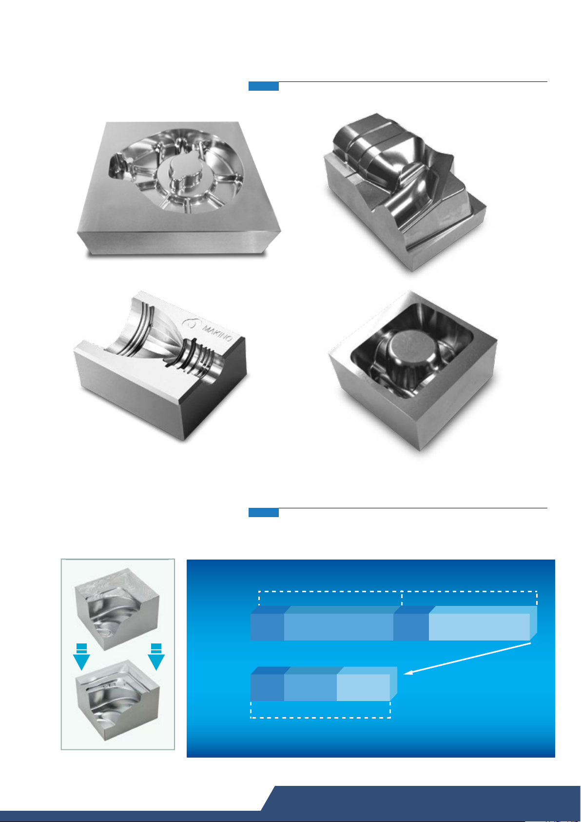
Superior Surface Finish
Die cast Die
Plastic mold
High Efficiency Machining
Stamping die
Forging die
Machining hard materials from rough to finish,
increasing productivity and efficiency
Surface Finish: Ra 1µm
General
Process
MAKINO
Process
Setup
Setup
Roughing
All in One Machine
Machine 1Machine 2
Roughing
Finishing
Setup
Finishing
30-50%
05
Page 6

Rigid Structure
Heavy cast iron construction and a unique axis configuration
provides outstanding stiffness, rigidity, thermal stability, accuracy
and unequaled axis support throughout the full travel of each axis:
• X and Z on the column
- Constant spindle support distance
- Fully supported throughout travel
• Y under table
- No “stack-up” of X and Y
- No off-center table load condition
- Fully supported throughout travel
Finite Element Analysis (FEA) of the basic components
insure optimized structural rigidity and tortional stiffness for
ultimate performance characteristics and consistent results.
This structural rigidity is the foundation for superior cutting
performance, provides damping against vibration, and
sustained accuracy for the life of the machine.
Most competitive machines feature some variation
of a traditional "C-frame" design. Therefore, in most
die and mold applications, by virtue of the machine
configuration and associated geometry, the machine
tool elements significantly overhang their support
structure:
•The Z axis is cantilevered from the X axis (Figure 1)
•The X axis is “stacked up” on the Y axis (Figure 2)
•The X axis is overhung from the Y axis (Figure 3)
Overhung
Z-axis
T
N
T
N
E
M
O
M
Z
Y
“Stack up”
X on Y - axis
E
M
O
M
Z
Y
As a result, cutting forces - combined with these long,
unsupported, cantilevered distances create stiffness,
rigidity and dynamic distortion issues that produce
vibration and chatter. Such instabilities, inertial factors
and bending moments during cutting dramatically
impact surface finish, final part accuracy, cutting
speeds and feeds, achievable depth of cut, cycle time,
tool life, and productivity. By virtue of the unique
F-series construction, the machine provides a stiffer,
more rigid, highly accurate, chatter-free platform for
even the most difficult of cuts.
Z
X
Overhung
X-axis
M
O
M
E
N
T
“Stack up”
X on Y - axis
06
Figure 1 Figure 2 Figure 3
Page 7

Thermal Stability
High performance linear guideways (utilizing
“caged ball” technology) provide extremely precise,
anti-friction motion. In addition, pre-tensioned, dual
supported, large diameter ballscrews and powerful,
direct-coupled, digital servo motors - tuned for peak
performance - provide the stiffness and rigidity for the
most challenging applications.
Fine ballscrew motion provides greater precision
for blends, matches and complex geometry
applications. Temperature controlled lubrication
maintains and controls the thermal stability of the
ballscrew bearing mounting area, ensuring stable,
long cycle time cutting accuracy.
OUT
IN
Lubrication of support bearing of X & Y Axis
• Thermally stabilizes support bearing as
it is bathed with oil flow
• Extends life span of the support bearing
• Smoothens axis movement especially
during small step machining
OUT
IN
Achieving High Precision Accuracy Through Mechanical Means
Parts are accurately manufactured, meticulously adjusted and
assembled with exacting precision.
Scrapping is incorporated in the machine assembly in order
to achieve better profile accuracy and surface matching which
results to mechanical accuracy in order to further enhance and
increase the machine performance and increase the machine
life at the same time.
Machining accuracy
Squareness 0.005 mm / Full Stroke
Straightness 0.005 mm / Full Stroke
(*Guaranteed values: tolerance at Makino's assembly
plant - daily temperature change of ±10C)
(*In accordance to JIS B6338 - 1985)
07
Page 8

Advanced Spindle Technology
Makino’s leadership in spindle technology is renowned throughout the world. Spindle rigidity,
higher rpm, constant pre-load, multi-plane balancing, minimizing vibration, and controlling thermal growth
are all issues that Makino has solved through years of experience and application of spindle design,
manufacture, and assembly.
The optional 20,000 rpm, HSK-A63 spindle
incorporates Makino’s patented spindle technology:
Spindle core cooling
Under-race bearing lubrication
Closed loop oilmatic temperature control
The spindle provides characteristics required in any
number of high-speed machining applications
typical of the die and mold industry. The two-range,
unique integral design provides wide-range capability
with stiffness and rigidity at lower ranges (roughing
operations) to vibration & chatter-free production of
small details and fine features when using small tools
at a high rpm.
Spindle Temperature Controller
The F-series machine is the only machine of
its class to combine a large capacity, heat
dissipating spindle chiller, and the Makino technologies
mentioned above. This maintains tight control over the
spindle, bearings, and motor area, thus minimizing any
spindle thermal growth effects upon spindle pre-load
that impacts spindle stiffness and rigidity, tool life,
surface finish, and ultimately final part accuracy.
Cooling oil
support port
Cooling oil exit
Spindle BT40 HSK-A63 HSK-F63
12,000 rpm
20,000 rpm
30,000 rpm
Legend
- standard - option x - N/A
x x
x x
x
HSK spindle (Option)
The HSK shank system with two restrained faces
simultaneously couples the taper portion of the shank
and the flange end face.
HSK-A63 holder
*Available for
20,000 rpm spindle
HSK-F63 holder
*Available for
30,000 rpm spindle
1. Improved Heavy-Duty Cutting Performance
The difference in cutting performance is especially
noticeable when machining with longer shank tools.
2. Improved Accuracy
Excellent attachment accuracy is faithfully reproduced
for greater machining accuracy. This system firmly
secures the tool holder both on face and the shank and
provides very high rigidity and improved accuracy.
Strongly recommended for high-speed applications.
08
Page 9

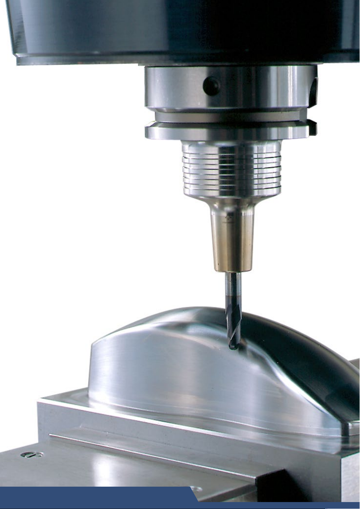
120 ~ 12,000 rpm Spindle
This high-torque spindle provides superior
heavy-duty cutting performance for handling a
wide range of machining.
12,000 rpm Spindle
Performance Characteristics of Standard Spindle
Spindle power (kW)
1,500 rpm
2,500 rpm
3,500 rpm
5,000 rpm
4,000 6,000 8,000 10,000 12,000
2,000
Spindle speed (rpm)
Torque (Nm)
10,000 rpm
200 ~ 20,000 rpm Spindle
This high-speed spindle is ideal for high-speed
machining. Versatile for handling a wide range
of medium to small diameter tools.
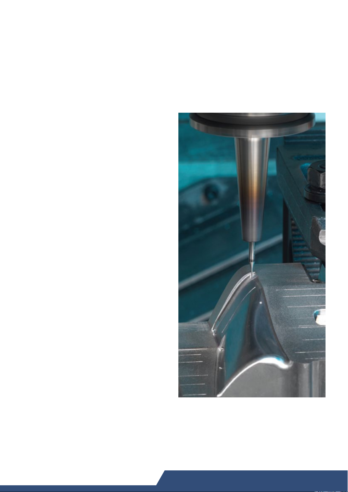
300 ~ 30,000 rpm Spindle
This high-speed spindle is ideal for high-speed
machining with small diameter tools, such as
hair-line machining.
20,000 rpm Spindle
Performance Characteristics of High-speed Spindle
3,300 rpm
3,800 rpm
Spindle power (kW)
2,000 4,000 6,000 8,000 10,0 00 12,000
(Optional specification)
3,300 rpm
7,500 rpm
5,500 rpm
12,000 rpm
20,000
Spindle speed (rpm)
30,000 rpm Spindle (Optional specification)
Performance Characteristics of High-speed Spindle
240
220
200
180
160
140
120
100
80
60
40
20
Torque (Nm)
Spindle power (kW)
Spindle speed (rpm)
Torque (Nm)
30,00025,00020,00015,00010,0005,000
09
Page 10

Motion Technology
Super Geometric Intelligence (SGI.4) software - developed specifically
for high feedrate, tight tolerance machining of complex, 3D-contoured
shapes involving continuous tiny blocks of NC data. It ensures production
rates faster than standard CNC systems while maintaining high accuracy.
SGI.4 helps provide the lowest cycle time and cost.
• Fine Motion Control Even At High Feedrate
• F series Provides advanced acceleration and deceleration
control technology
• High-Speed & High-Accuracy machining made possible
• Enhanced cutting point accuracy
• Cutting mode selection
• CMD optimized machine
• Look ahead
• HPCC (High Precision Contour Control)
G.I. & S.G.I.
8
6
4
2
Direction (X-Y) CW CCW
Diameter, mm 20 20 20 20
Feedrate, mm/min 200 8,000 200 8,000
Roundness, µm 1.1 4.8 1.4 4.8
(*Guaranteed values: tolerance at Makino's assembly plant - daily temperature change of ±10C)
(*In accordance to JIS B6338 - 1985)
Technology by others
F series Technology
Direction (Y-Z) CW CCW
Diameter, mm 20 20 20 20
Feedrate, mm/min 200 8,000 200 8,000
Roundness, µm 1.9 5.7 1.6 5.4
Dynamic Calibration of 3 Axes
YZ Plane
XY Plane
The machining mode that optimally matches the machining job can be selected with M code commands.
High
Performance
Mode
M251
High
Accuracy
Mode
M250
Ultra High
Accuracy
Mode
M252
10
High Speed High accuracy
With Super GI.4 controlWithout GI control
Page 11

Pro 5 Controller
F series utilizes the Makino Professional 5 Control which affords the
perfect blend of a Windows CE graphical user interface (GUI), touch-screen
selection that provides instant access to information literally at your
fingertip, user-friendly, efficient PC-like capability for data management
and editing, and the networking and storage capability of a Makino
proprietary data center.
Key Features
Controller
• Data Center
• Tool Data Screen
• Machine uptime
management
• Alarm Display
Tool Data
– Single screen to check, edit and manually read/
write NC data
– Spindle load, tool life and tool data management
– The operating time for each machining process is
recorded as a machining result
– Easy to understand alarm display screen for
quick machine recovery
Spindle Load
& Tool Life
ATC
Recovery
Preventive
Maintenance
Machine Uptime
Management
11
Page 12

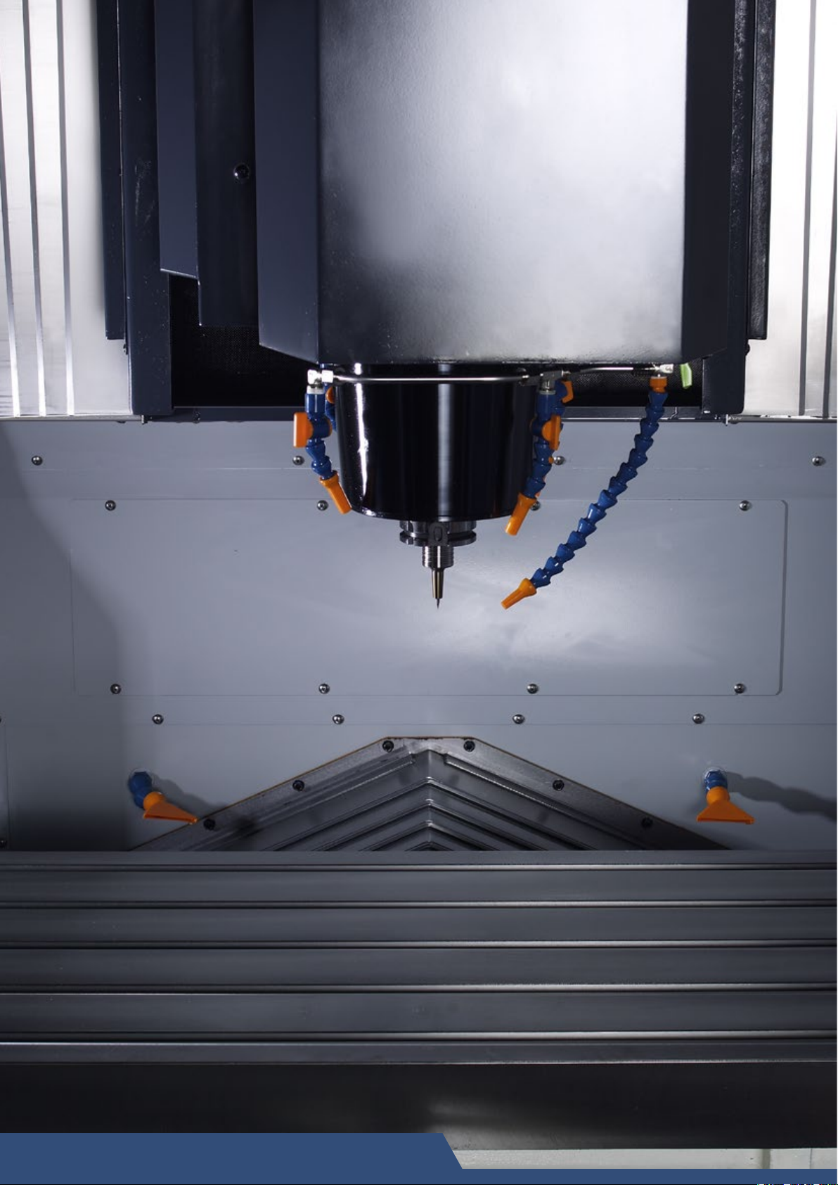
Efficient Chip Removal
5 nozzles supply device (standard specification)
• 4 coolant nozzles and 1 air blower nozzle are effectively positioned around the spindle.
Through-spindle air (optional specification)
• Air is supplied from the tool tip and holder.
Through-spindle coolant (1.5 MPa and 3.0 MPa) (optional specification)
• Coolant is supplied from the inside of the holder through the tool tip.
Unmanned machining application and highly efficient machining processes generate high volume of
chips. Therefore, a quick, good and reliable machine chip evacuation system is required. In F series,
optional two spiral type chip conveyors is used in transporting chips from the machining zone to the
rear of the machine. This efficient system will enable operator to focus on the machining tasks and
hence improve his work efficiency.
Spiral Conveyor
Chip Tray is located at the front of the
machine and can be emptied even during
machining
An optional Rear Tank is equipped with 2 x spiral
conveyors to evacuate chips to the rear side of the
machine
12
An optional lift up chip conveyor can be installed
along with the rear tank to further improve the chip
management of the machine.
Page 13

The chip and splashguard doors, as well as
the machine ceiling, open together to facilitate
easy handling of large, heavy workpieces that
require an overhead crane. Combined with the
movement of the table, and the convenient
table loading height, the F-series machines
significantly reduces part exchange load times
and operator fatigue.
The machine control is on a pivot that provides
90° of swing. This assures the operator will
always have easy access to the control during
set-up, program prove-out, operation, and
even manual tool loading through the front of
the machine.
Ease of Operation
An integral ATC shutter separates the machine
workzone from the tool magazine, assuring the
chips and coolant from the machining area do
not migrate into the tool magazine.
The tool changer door provides ready access
for easy loading and unloading of tooling to
the machine magazine. An ATC control panel
is located adjacent to the tool changer door
to assist the operator in manual operation of
the tool magazine and double gripper for tool
replenishment and maintenance.
13
Page 14

Measurement Systems
Automatic tool length measuring device (contact)*
This device measures the length of small
diameter tools with diameter more than 0.5 mm.
An air blower is attached to remove chips and coolant
before the measurement so as to ensure that the tool
length is measured accurately.
Automatic workpiece measuring device*
This device can be programmed to measure
workpieces automatically before, during and after
machining.
Non-contact tool measuring device (laser type)*
This device measures the length & diameter of small tools.
14
*Optional Equipment
Page 15
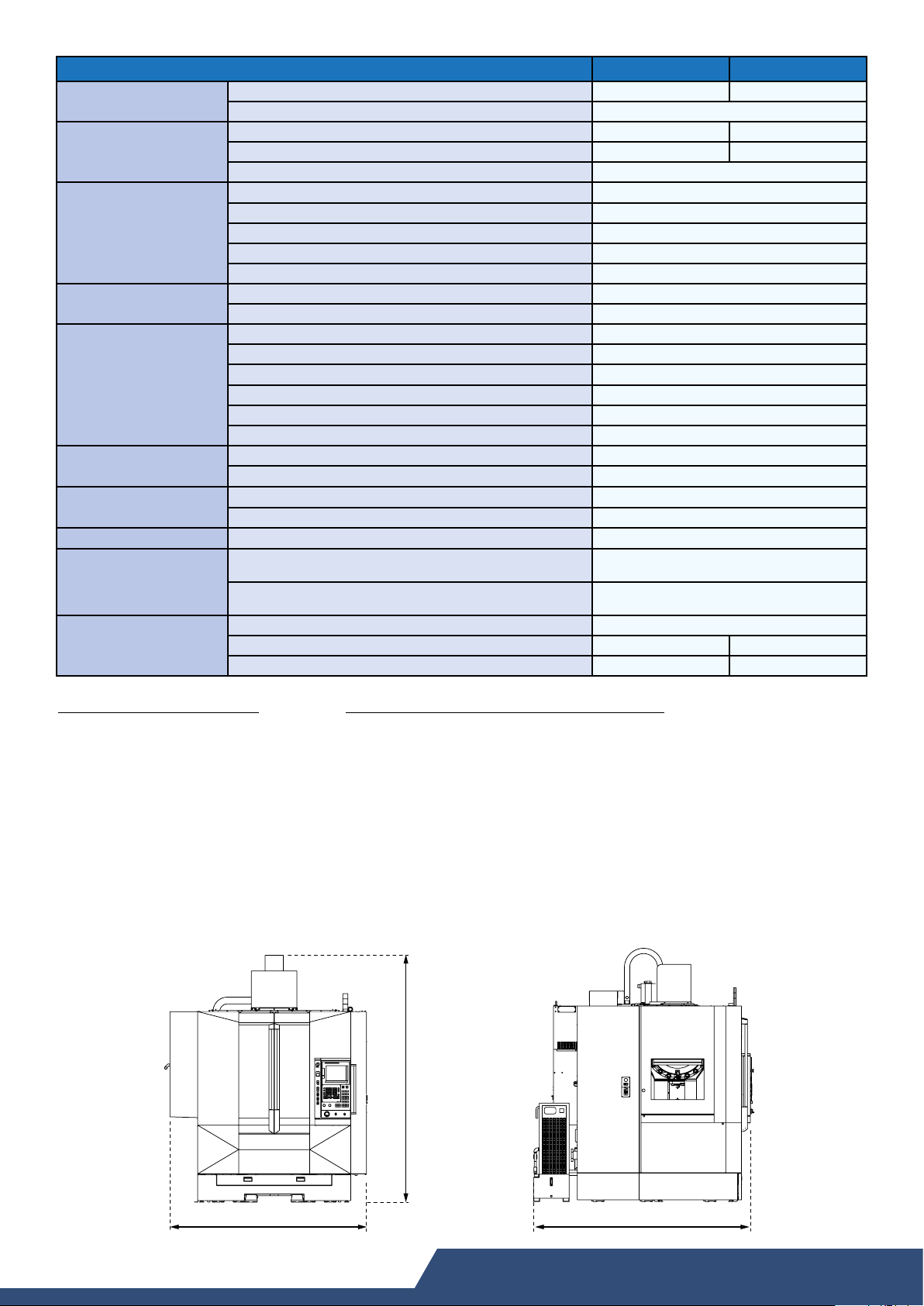
Machine Specifications
Travels
Table
Spindle
Feedrates
Automatic tool changer
Coolant tank
Air supply
Power supply (Standard)
Machine accuracy
(Tolerance measure at
Makino's assembly plant)
Machine size (Standard)
F3 F5
X x Y x Z axes
Distance from table surface to spindle gauge line plane
Table working area (WxD)
Maximum table load (Evenly distributed)
Table surface configuration 5 x T-slots, size 18H8 mm, pitch 100 mm
Spindle speed range
Spindle taper hole 7/24 taper No. 40
Spindle drive motor power (15 min. / cont.)
Spindle drive motor torque (15 min. / cont.)
Spindle bearing diameter (inner/outer)
Rapid traverse
Cutting feed
Tool shank type MAS 403 BT40 (JIS B6339 40T)
Tool storage capacity 20 tools
Maximum tool diameter (with adjacent pots occupied)
Maximum tool diameter (with adjacent pots empty)
Maximum tool length
Maximum tool weight
Tank capacity
Flowrate
Pressure
Consumption
Main electrical power capacity
Positioning (Full stroke without / with scale feedback)
Repeatability (Full stroke without / with scale feedback)
Height (H)
Floor space (W x D)
Weight
mm
mm
mm
rpm
kW
Nm
mm
mm/min
mm/min
mm
mm
mm
L/min
MPa
L/min
kVA
mm
mm
mm
mm
650 x 500 x 450 900 x 500 x 450
150 ~ 600
850 x 500 1,000 x 500
kg
800 1,000
120 ~ 12,000
22 / 18
117 / 95
Ø70 / Ø100
20,000
1 - 20,000
Ø 114
Ø 120
300
kg
L
8
160
80
Min 0.5 ~ 0.8
400
40 (AC 200V, 3P)
JIS Standards: ±0.0025 / ±0.0015
ISO 230.2 (1997) :≤0.010 / ≤0.006
JIS Standards: ±0.0014 / ±0.0010
ISO 230.2 (1997) :<0.006 / <0.004
3,065
2,440 x 2,625 2,565 x 2,625
kg
7,300 7,500
Standard Specifications
• 12,000 rpm spindle
• 20-tool ATC
• Automatic Air Blower
• Complete set of manuals
• Data Center A - 160MB
• Fixed Manual Pulse Generator (MPG)
• Fluorescent lighting within splash guard
• Helical Interpolation
• Makino Professional 5 controller
• Manual centralized lubrication system
• Nozzle coolant (4 nozzles)
• Number of registerable programs: 120
• Part program storage memory: 160 m
• Rigid tapping
• Splash guard door lock
• Super GI.4 control
Optional Specifications (•) & Equipment (
• 30-tool ATC
• HSK-A63 Spindle (for 20,000 rpm spindle)
• HSK-F63 Spindle (for 30,000 rpm spindle)
• Through spindle air
• Through spindle coolant (1.5/3.0 MPa)
▲ 4th axis NC rotary table interface
▲ Air dryer
▲ ATLM (Automatic Tool Length Measuring Device)
▲ Auto power out
▲ AWM (Automatic Workpiece Measuring Device)
▲ Lift-up Chip Conveyor
▲ Chip bucket for lift-up chip conveyor
F3 | F5: 3,065
▲ Mist collector
▲ MTC cabinet door interlock
▲ Portable manual pulse generator
▲ Power failure monitoring (3 axes)
▲ Rear coolant tank
▲ Scale feedback (X, Y, Z axes)
▲ Work wash gun
▲)
F3: 2,440 | F5: 2,565
F3 | F5: 2,625
15
Page 16

http://www.makino.com.sg
*The specifications in this catalog may be changed without prior notice to incorporate improvements resulting from ongoing R&D programs.
*The machines displayed in this catalog are fitted with optional equipment.
*The accuracy and output of machine may vary according to conditions of working environment.
*This product, including technical data and software, may be subjected to the Singapore Foreign Exchange and Foreign Trade Law.
* Prior to any re-sale or re-export of controlled items, please contact Makino to obtain any required authorization or approval.
Printed in Singapore AH010Ea 1511/2 (C/D)
 Loading...