

Page 1

3UH,QVWDOODWLRQ*XLGH
('*(
Makino EDGE2
Ram Electrical Discharge Machine
with MGF Control
Pre-Installation Guide
This guide is intended for use by Makino customers and Makino employees and assigns for the safe operation and maintenance of Makino equipment.
This guide was developed through the combined efforts of:
Makino Documentation Gro up - Mason USA
MBS Associates (Lynne Hays)
Makino Customer Support
st
Release Date: July 20, 2000
1
Copyright © 2000 Makino, Inc. All Rights Reserved
• No part of this manual may be reproduced or transmitted by any means or in any
form to parties other than which it is intended, without the expressed written
permission of Makino.
• All specifications and designs may change without notice.
Every attempt was made to ensure that the information in this publication was correct at
the time of printing. As specifications and designs change, Makino is not responsible for
information that becomes incorrect or inaccurate after publication.
20ED3A1863
(E)
i
Page 2
('*(
g
g
g
g
3UH,QVWDOODWLRQ*XLGH
The following ic ons are used in this document. Safety and precau tionary
statements are presented as shown below.
DANGER
A
existin
tions must be taken immediately to prevent personal injury or death.
WARNING
A
potentially hazardous situation with some probability of death or serious injury. Precautions must be taken immediately to prevent personal injury.
CAUTION
A
potentially hazardous situation with some probability of personal injury or dama
the machine. Precautions must be taken immediately to prevent personal injury or
machine dama
icon precedes each danger statement. A
hazardous condition with a high probability of death or severe injury. Precau-
icon proceeds each warning statement. A
icon proceeds each caution statement. A
e.
DANGER
WARNING
CAUTION
icon indicates an
icon indicates a
icon indicates a
e to
• Precautionary statements must be followed to prevent personal injury
or damage to the machine.
• In addition, all safety requirements and guidelines found in Chapter 1 Safety, the ANSI safety guidelines the Makino Safety Manual, shipped
with the machine, and established company safety requirements and
regulations must be followed. Taking personal responsibility for safety
will prevent most accidents.
Notes are presented using the following icon format
A NOTE icon indicates information that expands on information given or indicates
where additional infromation can be found. Notes are presented immediately followin
the applicable content.
A copy of the ANSI Safety Manual, ANSI document number ANSI B11.8
was shipped with the machine. If this manual was lost or misplaced,
another copy can be obtained from Maki no at no charg e.
Write us at: Call or FAX us at:
Makino
P.O. Box 8003
7680 Innovation Way
Mason Ohio, 54040-8003
Attn: Information Services
Phone: (513) 573-7200
ask for Information Services
FAX: (513) 573-7360
Attn: Information Services
ii
Page 3

3UH,QVWDOODWLRQ*XLGH
To contact Makino, for service after the sale:
Makino
7680 Innovation Way
Mason, Ohio 45040 USA
('*(
Technical Support Services
Mon.-Fri. 7:00 a.m. to 8:00 p.m.
Sat. 8:00 a.m. to 2:00 p.m.
(Eastern Standard Time)
Parts Express
24 hours, 7 days a week
Tr aining Services
(888) Makino4 (625-4664)
Fax: (513) 459-1825
(888) Makino1 (625-4661)
Fax: (888)-881-9289
(888) Makino1 (625-4661)
The following acronyms and abbreviations are used in this document:
Term Meaning
APC Automatic Pallet Changer- work table (pallet) storage and exchange device
ATC Automatic Tool Changer - tooling storage and exchange device
ccw counterclockwise - direction of rotation
CNC Computerized Numerical Control - control unit for machine tool system
cw clockwise - direction of rotation
DEC Deceleration - axis slow down for reference operations
DI Dielectric (i.e. DI Fluid, DI unit)
EOB End Of Block - program code at end of each block of data
E-Stop Emergency Stop - machine condition halting all machine operation
FPB Flexible Pendant Box - portable control and axis positioning device
FSE Field Service Engineer - customer service technician
LS Limit Switch - LS00 = limit switch 00
MDI Manual Data Input - operating mode for direct input of NC data
MTC Machine Tool Cabinet - Cabinet housing main machine electrics/electronics
NC Numerical Control - input data (i.e. NC program)
PM Preventive Maintenance - routine maintenance items and checks
S/G Splash Guard - machining area enclosure
SOL Solenoid - SOL01 = Solenoid 01
20ED3A1863
(E)
iii
Page 4

('*(
3UH,QVWDOODWLRQ*XLGH
AVISO!
Las personas que no pueden leer o entender en Ingles deben mandar traducir este
manual y solicitar entrenamiento antes de operar o mantener la maquina. Todos los
que trabajen en esta maquina deberan saber como operarla con toda seguridad y en
forma correcta para evitar un posible dano.
ATTENTION!
Les personnes ne sachant pas lire l'anglais devront se faire lire et expliquer le manuel
avant d'utiliser ou de faire l'entretien de la machine. Toute personne travaillant sur la
machine doit savoir comment l'utiliser sans danger et correctement afin d'eviter tout
accident.
HINWEIS
Alle Personen die nur Teile des Handbuches oder kein Englisch verstenen, müssen
sich dieses Handbuch erklären lassen, bevor sie die Maschine in Betrieb nehmen
oder instandhalten. Alle Personen, die an der Maschine arbeiten, müssen zur Vermeidung von Verletzungen zur korrekten Handhabung angeleitet werden.
WARNING!
Persons unable to read English or do not understand any part of this guide, must have
this guide read and explained to them before operating or maintaining the machine.
Everyone working on the machine must know how to operate and maintain it safely
and correctly to prevent possible serious injury.
iv
Page 5

3UH,QVWDOODWLRQ*XLGH ('*(
CONTENTS
Chapter 1 Safety Precautions
Chapter 2 Specifications
Chapter 3 Installation Process Overview
Chapter 4 Pre-Delivery Preparations
Chapter 5 Machine Delivery
Appendix A Conversion Factors
20ED3A1863
(E)
v
Page 6

('*( 3UH,QVWDOODWLRQ*XLGH
vi
Page 7

3UH,QVWDOODWLRQ*XLGH
Chapter 1 Safety Precautions
For a Safe Working Environment
Makino EDGE2
('*(
Ram Electrical Discharge Machine
with MGF Control
01_20ed3a Safety.fm
Page 8

('*(
g
g
g
g
g
g
g
g
g
3UH,QVWDOODWLRQ*XLGH
Chapter 1
Safety Precautions
Contents
1.1 Overview . . . . . . . . . . . . . . . . . . . . . . . . . . . . . . . . . . . . . . . . . . . .1 - 1
1.2 General Safety. . . . . . . . . . . . . . . . . . . . . . . . . . . . . . . . . . . . . . . .1 - 1
1.2.1 Dan
1.2.2 Access to Information . . . . . . . . . . . . . . . . . . . . . . . . . . . . . . 1 - 4
1.2.3 Point-of-operation . . . . . . . . . . . . . . . . . . . . . . . . . . . . . . . . .1 - 4
1.2.4 Lockout/Ta
1.3 Personal and Professional Safety. . . . . . . . . . . . . . . . . . . . . . . . . 1 - 6
1.4 Equipment and Operation Safety . . . . . . . . . . . . . . . . . . . . . . . . .1 - 7
1.5 Environmental Safety . . . . . . . . . . . . . . . . . . . . . . . . . . . . . . . . . 1 - 10
1.6 Liftin
1.6.1 Slin
1.6.2 Chains . . . . . . . . . . . . . . . . . . . . . . . . . . . . . . . . . . . . . . . . .1 - 11
1.6.3 Hooks . . . . . . . . . . . . . . . . . . . . . . . . . . . . . . . . . . . . . . . . . .1 - 12
1.6.4 Eye Bolts . . . . . . . . . . . . . . . . . . . . . . . . . . . . . . . . . . . . . . .1 - 12
1.6.5 Rin
1.6.6 Liftin
1.6.7 Liftin
1.7 Mechanical Maintenance Safety . . . . . . . . . . . . . . . . . . . . . . . . .1 - 14
er, Warning, Caution Statements and Symbols . . . . . . 1 - 2
out Procedure . . . . . . . . . . . . . . . . . . . . . . . . . . 1 - 5
Safety . . . . . . . . . . . . . . . . . . . . . . . . . . . . . . . . . . . . . . . .1 - 11
s . . . . . . . . . . . . . . . . . . . . . . . . . . . . . . . . . . . . . . . . . . 1 - 11
s . . . . . . . . . . . . . . . . . . . . . . . . . . . . . . . . . . . . . . . . . .1 - 12
the Machine or Components . . . . . . . . . . . . . . . . . . . 1 - 13
Workpieces and Fixtures . . . . . . . . . . . . . . . . . . . . . .1 - 13
1.8 Electrical Maintenance Safety . . . . . . . . . . . . . . . . . . . . . . . . . . .1 - 15
1.9 EDGE2 Ram Electrical Dischar
1.9.1 Fire Hazard and Prevention . . . . . . . . . . . . . . . . . . . . . . . . .1 - 16
1.9.1.1 EDM Fire Conditions . . . . . . . . . . . . . . . . . . . . . . . . . . .1 - 18
1.9.2 Machine Safety Features . . . . . . . . . . . . . . . . . . . . . . . . . . .1 - 20
1.9.3 Location of Emer
1.9.4 Location of Safety Labels . . . . . . . . . . . . . . . . . . . . . . . . . .1 - 21
1.10 EDGE2 Equipment and Operation Safety. . . . . . . . . . . . . . . . . 1 - 23
ency (E-Stop) Button . . . . . . . . . . . . . . . 1 - 20
e Machine Safety. . . . . . . . . . .1 - 16
Page 9

3UH,QVWDOODWLRQ*XLGH
1.11 Installation Safety Instructions. . . . . . . . . . . . . . . . . . . . . . . . . . 1 - 25
('*(
01_20ed3a Safety.fm
Page 10

('*(
OTES
N
3UH,QVWDOODWLRQ*XLGH
:
KETCHES
S
:
Page 11

1.1 Overview
This chapter provid es proven general safety guidelines t hat, if followed,
promote a safer working environment. It also contains safety information
specific to the EDGE2.
All machining centers have inherent haz ards the manufacturer either
designs out, guards against, or warns about. Even though the manufacturer has this responsibility, the machine user has ultimate responsibility
to ensure that a safe working environment is maintained in and about the
machining center. This includes, but is not limited to, allowing only properly trained and technically qualified personnel program, operate, and
maintain the machin in g cent er.
It is Makino’s po licy and respo nsibility to d esign, manu facture, and m arket
machining centers that are as reasonably safe as possible for their
intended use.
3UH,QVWDOODWLRQ*XLGH
('*(
1.2 General Safety
Safety precautions or requirements discus sed in Makino gu ides or manuals do not supersede any safety requirements imposed by local, state, or
federal governments. All government-imposed guidelines, i.e. OSHA
(Occupational Safety and Health Administration), NEC (National Electric
Code), NFC (National Fire Code), ANSI (American National Standard
Institute) standards, shall take precedence.
To protect against injury or damage operate the machining center within
the guidelines described in the provided documentation. Consider
Makino’s safety precautions supplemental to:
• Other Makino supplied guides or manuals related to programming,
operation, and maintenance of this specific machining center.
• Your company’s safety rules and regulations.
• All local, state, and federal regulations.
Your particular application may require additional safety measures to
ensure proper operator safety.
Additional copies of any guide or manual provided with your Makino
machining center may be purchased from Makino.
01_20ed3a Safety.fm 1 - 1
Page 12

('*(
3UH,QVWDOODWLRQ*XLGH
Prior To Installation, Operation, or Service,
Do NOT attempt to install, operate, or service this machining center until:
• You have read and under stand th e safety i nstru ctions containe d in th is
guide.
• You have read and understand all Danger, Warning, and Caution
safety labels attached to the machining center and its related equipment.
• You have read and understand all technical information, including the
following sections of this safety chapter.
Questions Regard ing Safe Operation
Before you operate this machine – contact your Makino service group for
answers to any questions about safety and your Makino machine.
1.2.1 Danger, Warning, Caution Statements and Symbols
It is important that all employees recognize each safety symbol on the
machine and understand the meaning of Danger, Warning, and Caution.
These safety labels must never be removed, covered, or painted over,
and must be replaced if they are damaged, defaced, or become unreadable.
Table 1-1
that all employees recognize and understand the meaning of the safety
symbols shown in
The location of safety labels for specific hazards on the EDGE2 is
described in
presents the meaning of each safety statement. It is important
Table 1-2
section 1.9.4
.
.
1 - 2
Page 13
3UH,QVWDOODWLRQ*XLGH
('*(
ABLE
T
1-1
DEFINITION OF DANGER, WARNING, AND CAUTION STATEMENTS
Statement Meaning
DANGER is the most severe safety statement. This statement means
DANGER
WARNING
CAUTION
ABLE
T
1-2
that either severe personal injury or death may result if the instruction(s) is not followed.
WARNING is the next level of safety statement. It indicates that if the
instruction(s) is not followed severe personal injury could result.
A CAUTION is the least severe safety statement and indicates that if
the instruction(s) is not followed damage to the equipment may result.
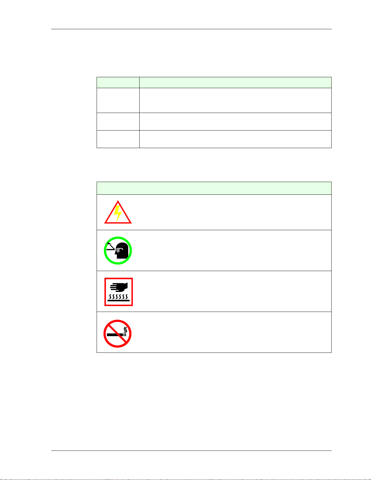
SAFETY SYMBOL SHAPES AND THEIR MEANING
Symbol Meaning
A triangle or diamond shaped safety symbol indicates a hazard
exists in the area or behind the enclosure where the symbol is
placed.
The symbol at left indicates an electrical shock hazard exists.
A solid colored circle shaped safety symbol with an icon inside indicates the action shown by the icon is mandatory.
The symbol at left indicates that safety glasses be worn.
A square shaped safety symbol is used to convey information relative to the area where the symbol is placed.
The symbol at left indicates the area is hot.
A circle shaped safety symbol with a diagonal slash across the
image indicates the action shown is prohibited in or around that
area.
The symbol at left indicates that smoking is not allowed in the area.
01_20ed3a Safety.fm 1 - 3
Page 14

('*(
3UH,QVWDOODWLRQ*XLGH
1.2.2 Access to Information
We strongly recommend that a copy of these safety instructions and all
provided guides , manuals, and technical information be kept near the
machine. This infor matio n shou ld be o rgan ized for quick acce ss and u sed
by operators, maintenance, and other personnel with duti es related to the
machining center.
Access to this information:
• May save a life.
• W i l l prevent or reduce injury, mis-operation, and machining center
damage.
In the event tha t parts of this information become damaged or unus able,
replace them immediately.
1.2.3 Point-of-operation
“Point-of-operat ion” should be safeguarde d to the greate st extent po ssible
for all machining operations.
In addition to panel locks, interlocks, and guarding, certain areas of the
machining center ar e colo r coded f or safet y. It is important that the origina l
color and vividness of these areas be maintained.
Different operations or applications may make the general purpose safeguards unsuitable and require additional safeguards. You and your company are required to use special safeguards in these situations.
To assist in designing point-of-o peration safeguards for specific machining center applications:
• OSHA has published a booklet called OSHA Publi cation No. 3067.
• Films regarding safety requirements for machine tools are available
from ANSI and trade groups such as NMTBA (National Machine Tool
Builders Association).
1 - 4
Page 15

3UH,QVWDOODWLRQ*XLGH
1.2.4 Lockout/Tagout Procedure
The machining center is powered by high voltage and other energy
sources that represent potential hazards. To reduce the risk of injury or
death establish, define, and practice a Lockout/Tagout procedure for the
equipment in your facility.
Lockout/Tagout defines a minimum safe procedure to be followed by persons who might be confronted with unexpected energizing, start-up, or
release of stored energy that could cause injury or death. At a minimum,
all Lockout/Tagout procedures should include:
Electrical Shock Hazards Exist - Work Safely
Failure to turn the Main Power disconnect to the Off position, lock it out, and tag it could
result in severe personal injury or death.
1. Set the machine’s Main Power switch to the Off position.
('*(
2. Affix a
near the machine’s Main Power switch, until all repairs are complete.
3. Turn the Main Power disconnect to the Off position.
4. Install an industry approved lockout device through the Main Power
disconnect handle.
5. Install a t amper-proof padlock onto the loc kout device. Al l persons
performing maintenance on the machine at the same time shall install
their own padlock onto the lockout device.
6. Disconnect the main power of all power sources (i.e. electrical, air,
hydraulic, etc.).
Use the Lockout/Tagout policy and procedures defined by your company.
If no Lockout/Tagout procedure has been communicated to you, please
ask your supervisor to provide and explain one or obtain copies of standards to develop and implement Lockout/Tagout in your plant.
• A NSI has issued a standar d to a ssist in th e desig n and developme nt of
a Lockout/Tagout policy. It is written as a guide to follow when determining the spec ific p roced ures and trai ning n ecessar y and appr opria te
to your plant operations.
DO NOT START
tag with your na m e and department at, on, or
- Copies of the ANSI standard are available from ANSI at 1430
Broadway, New York, NY 10018, ask for: Standard ANSI Z244.11982, or as modified, for personal protection - Lockout/Tagout Of
Energy Sou rces - Minimum Safety Requirements.
01_20ed3a Safety.fm 1 - 5
Page 16

('*(
3UH,QVWDOODWLRQ*XLGH
1.3 Personal and Pr ofessional Safety
General safety precautions should be practiced everyday, but never
become common place. Safety is the responsibility of every person on the
job site. In this regard, consider yourself responsible for safety in your
workplace. No on e is better positioned to eliminat e or prevent unsafe conditions than you. Each employee should practice the following, regardless
of their position, title, or labor grade:
• Approach and intercede anytime you witness unsafe procedures.
• Be prepared to report any condition which seems unsafe to your company’s safety department or any supervisory or management staff. It
could save lives. In particular report such things as:
- Missing or defective guards and protective devices.
- Leaks and spills of cutting fluid, lubricants, or any liquids.
- Improperly stored chemicals or flammable materials and any
unusual fumes.
- Loose, worn, or broken flooring.
- Slippery, broken, or unstable platforms.
- Missing, broken, or unstable handrails.
• A v oid making sudd en movemen ts, loud noise s, engagi ng in horsep lay,
or other activities that may prove distracting and result in an unsafe or
dangerous work environment. Remember that around machinery, it
only takes a second’s inattention to result in personal injury or death.
• Observe and obey all signs posted on the machinery and its components and sign s placed by your company, like:
- NO SMOKING
- SAFETY GLASSES MUST BE WORN WHILE OPERATING THIS
MACHINE
- DANGER - HIGH VOLTAGE, etc.
• Wear appropriate safety equipment as defined by OSHA, the equipment manufacturer, your company safety policy, or MSDS (Material
Safety Data Sheet). Always wear approved eye protection and other
safety equipment to meet the demands of current conditions while
operating or working around the machining center.
1 - 6
• Clean up any oil or other liquid spills immediately.
Page 17

3UH,QVWDOODWLRQ*XLGH
• Obtain an MSDS for each chemical (such as cutti ng fluids, lubricating
oils, greases, etc.) used on or around the machining center. Practice
safe working ha bits and wear all protective equipment required. Know
and understand the procedures to follow in the event:
- Your skin is exposed to the chemical.
- Your eyes are contacted by the chemical.
- You ingested or inhaled the chemical.
1.4 Equipment an d Op e ration Safety
We urge that all machining centers be operated, equipped, and cared for
in strict compliance with all local, state, and federal safety regulations. The
following safety requirements apply to all machinery and should be practiced in addition to machine specific safety guidelines.
• Do not neglect your responsibility to ensure that all machining centers
are operated, mai ntain ed, and eq uipp ed with compl ete r egar d for o perator safety.
('*(
Only qualified personnel, trained in safety and all machining center functions should be allowed to operate, maintain, or repair the machine.
To be considered qualified, all personnel whose duties are related to the
operation, maintenance, or repair of the machining center should:
• Know the location and operation of t he [
ton.
• Study the related guides or manuals prior to attempting to operate,
maintain, or repair the machine.
• Locate and understand all
machining center and accessories.
Machining centers are designed for operation by one person at a time.
• P ersons other than the designa ted operato r should stay ou t of the area
during operatio n.
• Unauthorized personnel may increase the potential for injury or damage due to inattentiveness.
Danger, Warning,
EMERGENCY
and
Caution
] (E-Stop) but-
labels on the
01_20ed3a Safety.fm 1 - 7
Page 18

('*(
3UH,QVWDOODWLRQ*XLGH
Be sure to Always:
• Take steps to protect the machine tool and control cabinets from moisture and condensation. Moisture can damage electrical components,
causing unwanted machine motion, leading to injury or machin e damage.
• Maintain the exact original color and vividness of any machine areas
that are color coded as safety precautions.
• Ensure that all shields and gu ards are in place and all covers, cabinet
doors, and terminal boxes are closed prior to operation.
• Avoid accidentally bumping any machine controls, as this may cause
unintended machine motion causing injury or machine damage.
• Be alert for loose, damaged, or worn parts on the machine and associated equipment. Immediately correct or report any loose items, noticeable change in operating noise, or any unusual machine action.
• Be aware of the machine and auxiliary components’ moving members
and range of movement which may create pinch points. Always be
cautious of these areas. Avoid pinch points entirely during machine
operation.
• Keep the machining center properly maintained. Perform maintenance
at prescribed int ervals, as describe d in the Mechanical Editions.
Machining center maintenance should be performed only by authorized individuals.
• Check the level of each fluid reservoir periodically. Add fluids, if
needed, as described in the Mechanical Editions. Use only recommended lubricants.
• Keep the machining center clean. Keep the work area clear of chips,
rags, etc. Clean up any spilled or splashed fluid on the floor immediately. Cleaning should be performed at least daily.
• Double check the set up and workpiece before power up.
• Check all clamp bolts for tightness and verify the accuracy of all set
ups before restarting machining operation.
• U se caution when handli ng workpieces after machini ng. Machining can
produce sharp edges and, at times, considerable heat.
1 - 8
Page 19

3UH,QVWDOODWLRQ*XLGH
('*(
You should:
• N ever wear loose -fitt ing cl othing or acc essories tha t may be entan gled
in machine components. In particular, never wear any of the following
items when working in a shop environment:
- Jewelry (rings, bracelets, watches, or necklaces) and accessories
(necktie, scarf, or loose fitting belt)
- Long hair (tie back and contain it under a hair net or cap)
• Never operate any machinery after taking strong medication, using
nonprescription drugs, or co nsuming alcoholic beverages.
• Do not make modifications to the machine or associated equipment
that may reduce the operational safety of the device such as:
- Never paint, alter, deface, or remove any danger, warning, or cau-
tion label. (Rep lacement labels are available from Makino)
- Never change or by-pass the location of the stroke limit dogs, limit
switches, interlock circuitry, etc.
- Never operate the machine with any safety device disabled or
removed or any cover open or removed
• Do not allow yourself to become trapped or caught in pinch points:
- Always be aware of a safe exit, when in or around any type of
equipment. Know the travel limits of the machining center and
always keep all body parts clear of moving components.
- Never enter an area restricted by a barrier without first properly
shutting down the equipment and locking out the power sources to
prevent its restarting.
- Never perform any set up, check the set up, or reach into the work
area or across moving par ts while th e mach ine is in autom atic ope ration.
- Never change a workpiece or perform a manual operation on a
workpiece while the machine is in automatic operation.
• Never activate or press any button or other operating control unless
you are trained on t he ope ration of that d evice, ma chine , or e quipm ent.
• Never use compressed air to clean or blow chips or dirt off the table,
workpiece, or the machining center.
01_20ed3a Safety.fm 1 - 9
Page 20

('*(
3UH,QVWDOODWLRQ*XLGH
1.5 Environmental Safety
Follow these specif ic practices when work ing at the machining center:
• T he area arou nd the machine shou ld be well lig hted, dry, and free from
obstructions. Keep the area around the machine clean and in go od
order at all times.
• Equipment should not be operated during severe thunderstorms or
other electrical disturbances.
• In the event of a power failure, turn the Main Power switch Off immediately. Leave the switch in the Off position until the power is fully
restored and no rmal operations can safely be resumed.
• Never step on machine covers as they can become slippery during
normal operation and are not designed to support your weight.
• Never perform grinding operations in the vicinity of the machining center. The dust created by grinding can contaminate components, cause
premature wear, and cause inaccuracies or component failure .
• Never weld on parts mounted on or in the machine. Electrical cu rrents
associated with welding could cause bearing damage or explosions
and result in serious injury or equipment damage.
• When a platform is placed around the machining center, it should be
extremely sturdy, safe, and have anti-slip surfaces.
• Keep all flammable liquids away from the work area.
1 - 10
Page 21

1.6 Lifting Safety
These lifting safety precautions must be followed by all persons responsible for lifting. This includes, but is not limited to , lifting machinery, machine
components, and workpieces:
• All lifting equipment must be properly rated for the weight being lifted.
• All lifting equipment must be inspected on a regularly scheduled basis.
• A ny lifting device fo und to be defe ctive must be repa ired in accord ance
with industry standards.
• Any lifting device that cannot be repaired mus t be destroyed.
1.6.1 Slings
Use nylon slings when lifting irregularly shaped objects and:
• Never exceed the lifting capacity of any sling.
3UH,QVWDOODWLRQ*XLGH
('*(
• Protect slings with heavy padding when lifting objects with sharp
edges.
1.6.2 Chains
Lifting chains must be stored prop erly to prevent da mage when not in use.
When using chains:
• Never exceed the lifting capacity of any chain.
• Do not drag chains.
• Do not allow chains to become tangled or kinked.
• Never twist chains in an attempt to shorten their length. Use proper
devices to shorten a chain’s length.
• Use chains equipped with enclosed lifting hooks.
01_20ed3a Safety.fm 1 - 11
Page 22

('*(
1.6.3 Hooks
When using hooks:
• Never exceed the lifting capacity of any lift hook.
• Do not repair lifting hooks.
• Destroy and discard bent lifting hooks.
1.6.4 Eye Bolts
To ensure a safe load carrying capacity:
• Never exceed the lifting capacity of any eye bolt.
• An eye bolt must be en gaged to at least 90 per c en t of its threaded portion.
• Never weld or heat an eye bolt to a temperature in excess of 480° C
(900° F). Heat exposure can change the physical properties of the
stock and create an unsafe eye bolt.
3UH,QVWDOODWLRQ*XLGH
• Never use an inch eye bolt in a metric thread or vice versa:
- Use inch series thread eye bolts in inch series threads.
- Use metric series thread eye bolts in metric series threads.
• Never use a painted or coated eye bolt as this may cover up defects.
• Discard and destroy any defective eye bolts.
1.6.5 Rings
When possible use a lifting ring or clevis instead of an eye bolt. Secure the
lifting ring with the correct inch/metric series bolt.
• Never exceed the lifting capacity on any lifting ring or clevis.
1 - 12
Page 23

3UH,QVWDOODWLRQ*XLGH
1.6.6 Lifting the Machine or Components
Use only a lifting dev ice and relate d equi pment t hat is capa city ra ted to li ft
the total weight of the machining center (and shipping skid, if the skid is
attached during lifting). Always follow the lifting instructions provided in the
Pre-Installation Guid e.
Before lifting, refer to shipping documents to obtain the weight of the
machine or component being lifted. If the necessary weights cannot be
determined, consult Makino. In addition:
• Only qualified riggers should perform machine lifting operations.
• Never place any portion of your body beneath a suspended object.
• Lift the machining center only at the designated lifting points.
• Never lift the machine higher than necessary.
• Always maintain the center of gravity by properly adjusting the leg
lengths of the lifting device.
('*(
1.6.7 Lifting Workpieces and Fixtures
Always use a lifting device and related lifting equipment that is capacity
rated for the workpiece or fixture being lifted.
• Never place hands, arms, feet, or any other portion of your body
beneath a suspended workpiece fixture.
• Always maintain the center of gravity by properly adjusting the leg
lengths of the lifting device.
01_20ed3a Safety.fm 1 - 13
Page 24

('*(
3UH,QVWDOODWLRQ*XLGH
1.7 Mechanical Maintenance Safety
Mechanical maintenance procedures for Makino machining centers
should be performed by properly trained and technically qualified personnel. They should ad here to the se specif ic pra ctices wh en wo rkin g wi th th e
machining center:
• Always perform Lockout/Tagout before removing any safety guard,
cover, barrier, or any basic component of the machining center. See
section 1.2.4
• Block vertical sliding members before disassembling any portion of
their drive train.
.
• B e familiar with and adhere to safe lifting practices described in
before lifting the machine or components.
1.6
• Never return the machining center to production until all safety guards,
covers, barriers, or other safety devices are reinstalled and confirmed
operational.
section
Mechanical Maintenance Equipment
Mechanical maintenance personnel should:
• Keep all hand tools in good repair.
• Use each hand tool in a manner for which it is intended.
• Never use any hand tool that is defective, broken, or worn out.
• Keep alert with regard to nearby hazards.
• Do not use extenders in an effort to gain leverage; use a bigger tool.
1 - 14
Page 25

3UH,QVWDOODWLRQ*XLGH
1.8 Electrical Maintenance Safety
Electrical maintenance procedures for Makino machining centers must be
performed by properly trained and technically qualified personnel. They
should adhere to these specific practices when working with the machining center:
• Always perform Lockout/Tagout before working on electrical circuits.
See
section 1.2.4
• Use extreme care when troubleshooting with power On.
• With the power Off, identify and discharge any power retaining
devices, such as capacitors, before starting any maintenance procedure within any electrical control cabinet.
.
Electrical Maintenance Equipment
Use only industry standard approved electrical testing equipment.
('*(
• Volt/Ohm Meters.
• Oscilloscopes.
• Static Ground Wrist Straps.
Machine Grounding
All Makino machin ing centers must be properly grounded at the time of
installation.
• JIS class 3 grounding (resistance of 100 Ohms or less) is recommended.
• Proper grounding requires an isolated earth ground.
• Ground the machine in accordance with local, state, and federal regulations.
Machine Electrical Devices
Always replace defective electrical components, such as fuses, shunts,
overloads, etc., with components of the same capacity and rating as the
original equipment. If you are unsure of the correct electrical component
or part, refer to the machine’s electrical drawings or consult Makino.
01_20ed3a Safety.fm 1 - 15
Page 26

('*(
g
3UH,QVWDOODWLRQ*XLGH
1.9 EDGE2 Ram Electrical Discharge Machine Safety
In addition to safety precautions for all machining operations, Become
familiar with the machine specific safety features listed below.
1.9.1 Fire Hazard and Prevention
Fire Hazard
RAM type EDM uses a dielectric fluid in the machining process. This fluid is flammable
and may i
All Makino RAM machines are provide d with the following fire related
safety features:
1. Dielectric Temperature Detector – to immediately stops the machining
process when the temperature of the dielectric fluid rises above a set
value of 53°C.
nite, if improperly applied.
2. Dielectric Level Detector – to immediately stops the machining process when the dielectric level falls below the set level. The set level
must be at least 50mm above the workpiece.
3. Abnormal Machining Detector – stops the machining process if an arc
occurs for an extended duration. During an arc the head retracts to
clear the problem. If the head retracts beyond a specified distance,
machining stops and an “abnormal machining” alarm is generated.
4. Automatic Fire Extinguisher – If the dielectric fluid catches fire a sensor detects the temperature rise and discharges the extinguishing
agent into the work area. Additionally, all machine functions stop and
an audible alarm sounds. To resume machining operations, you must
change filters and di electric fluid t o remove the exti nguishing age nt. Do
NOT remove or chang e th e p ositi on s of the fire extinguishe r senso r (s)
or jet nozzle(s).
1 - 16
Page 27

3UH,QVWDOODWLRQ*XLGH
('*(
Be sure to Always:
• Keep all fire extinguishers fully maintained and operational and train all
personnel in their proper use.
• Ensure the automatic fire extinguisher is f ully operational. Perform a
functional test at the prescribed intervals. Never operate the machine
with the fire extinguisher testing knob in the "LOCK" position.
• In stall addition al fire extinguisher s of a type for liquid app lications in the
work area.
• Fully ventilate the work area at all times.
• Pay attention to the mounting method of the electrode, workpiece and
fixture so that electrical discharge does not occur near the surface of
the dielectric.
• Monitor the machining process. Never leave the machine totally unattended for extended periods of time. Allocate workers in such a manner that necessary measures can be taken if a problem occurs or if a
fire arises.
• Use only approved dielectric fluids.
You Should Never:
• Never substitute any oth er flammable liquids, such as kerosene for
dielectric fluid.
• Never use fire or heat sources such as heaters, welding machines or
open flame, near the mach ine.
• Never machine with fluid only being jetted onto the workpiece.
• Never machine with less than 50mm of dielectric fluid covering the
workpiece.
01_20ed3a Safety.fm 1 - 17
Page 28

('*(
3UH,QVWDOODWLRQ*XLGH
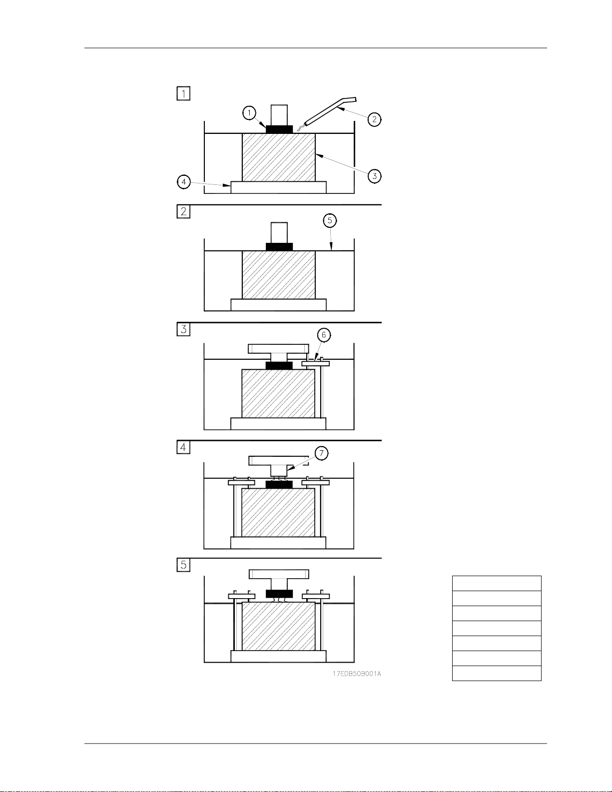
1.9.1.1 EDM Fire Conditions
The following conditions may result in fire during machining operations
(
Figure 1-1
1. Fire hazard caused by spray ing dielectr ic fluid onto workpiece. Workpiece shou ld be submerge d in the dielect r ic fluid to ensure safe bu rning.
2. Fire hazard from mach ining without e nough dielectri c fluid covering th e
workpiece. Dielectric level must be 50mm above the top of the workpiece.
3. Fire hazard from machine platen contacting a clamp. Ensure mo ving
machine members will clear clamps, work piece, and fixturing.
4. Fire hazard due to arcing between shank and electrode. This is
caused if the electrode becomes loose or is im properly mounted.
).
5. Fire hazard due to carbon build up is caused by a combination of too
little dielectric fluid covering the part and arcing.
6. Fire hazard can be caused by concave electrode shape (not shown),
as gas can collect in cavity. Ensure a vent hole is drilled at the high
point of the cavity.
1 - 18
Page 29
3UH,QVWDOODWLRQ*XLGH
('*(
Legend
[1] Electrode
[2] Jet Nozzle
[3] Workpiece
[4] Table
[5] Dielectric
[6] Clamp
[7] Shank
IGURE
F
01_20ed3a Safety.fm 1 - 19
EDM FIRE CONDITIONS
1-1
Page 30
('*(
3UH,QVWDOODWLRQ*XLGH
1.9.2 Machine Safety Fe atures
The EDGE2 provides the following safety features:
EMERGENCY
•[
] button, to immediately halt all machine functions.
• Automatic Fire Extinguisher and other fire related equipment, see
tion 1.9.1
Descriptions, operational detail, and precautions related to these safety
features are described in the Operation Guide.
(pg 1-16)
.
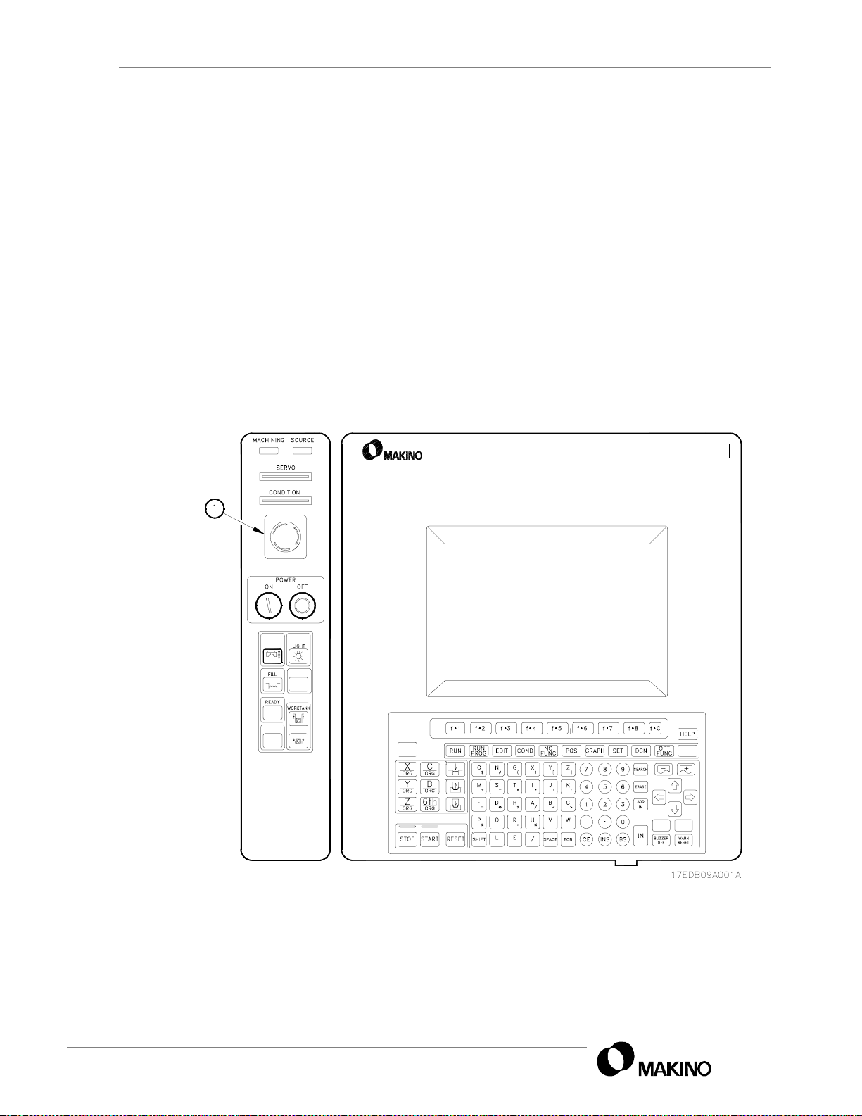
1.9.3 Location of Emergency (E-Stop) Button
EMERGENCY
The [
] button [1] is on the Main operation panel (
sec-
Figure 1-2
MGF
).
1 - 20
IGURE
F
EMERGENCY BUTTON LOCATION
1-2
Page 31

3UH,QVWDOODWLRQ*XLGH
1.9.4 Location of Safety Labels
Labels attached to the machine at specific areas, ident ify safety risks and
provide important instructions that must be read and followed.
('*(
• Machine safety labels (
• Oilmatic safety labels (
Figure 1-3
Figure 1-4
)
(pg. 1-22)
)
IGURE
F
01_20ed3a Safety.fm 1 - 21
MACHINE SAFETY LABELS
1-3
RIGHT VIEW
-
Page 32

('*(
3UH,QVWDOODWLRQ*XLGH
IGURE
F
OILMATIC SAFETY LABELS
1-4
1 - 22
Page 33

3UH,QVWDOODWLRQ*XLGH
1.10 EDGE2 Equipment and Operation Safety
('*(
In addition to the general safety precautions in
specific practices when working with the EDGE2.
section 1.2
, adhere to these
Be sure to Always:
• Inspect all tool holders for nicks or other damage to ensure the accuracy of machining operations and prevent damage to the equipment.
• Check with the manufacturer to ensure proper and safe operat ion in a
RAM EDM environment, of any accessory NOT specifically built,
designed, or s upplied by Makino .
• Use extreme caution when changing electrodes. Make sure that all
electrodes are properly loaded and secured and that they will not come
into undesirable contact with items in the work ar ea during oper ation.
• Load or unload workpieces only when the machine is completely
stopped and the control is in the STOP or RESET status.
• DRY RUN machining programs to verify that there is no chance of any
interference be twee n an y mach ine pa rts, f ixtur ing, and wor kpie ce pr ior
to unattended operation of the machine.
• Before moving the X, Y, or Z axes, make sure that there are no
obstructions within the range of movement.
• Check the tightness of all clamping devices, fixture mounting, electrodes and tool holders prior to any machining operations. Be sure to
verify the acc uracy of the set up prior to automatic operations.
You should Never:
• Never use any device NOT specifically designed for use in an EDM
environment. The dielectric fluid and electrical energies will cause
damage to improperly designed devices.
• N ever lay too ls on t he machi ne wher e they may i nter fere wi th machi ne
movement or can become entangled with the work.
• Never exceed the machines specified maximum workpiece weight
(500kg) or electrode weight (50kg).
• Never perform any set up work while the machine is in operation.
01_20ed3a Safety.fm 1 - 23
Page 34

('*(
3UH,QVWDOODWLRQ*XLGH
Working Inside the Machine
When working inside the machine be aware that axes and work tank operation are hazards that could result in serious injury or death. Therefore:
• Enter the machining area only when all machine motion is completely
stopped and the control is in the STOP or RESET state.
• Remember injury can occur if any body parts are caught between top
of the work tank and the workpiece or fixture or between work tank bottom and a platform or steps set near the machine.
• Ensure the Flexible Pendant Box cable does not interfere with the
workpiece or fixture.
• Always place the Flexible Pendant Box to prevent accidental key activation resulting in unexpected machine movement.
Prior to Machining
• Check with the manufacturer of any accessory not designed, built, or
supplied by Makino to ensure the device will opera te properly and
safely under the proposed operating conditions.
• P rio r to unatte nd ed op eratio n, p rove ou t p art p rogram s t o ensu re cl earance between machine parts, fixturing, and the workpiece.
• Before moving the axes, make sure there are no obstructions within
the range of movement.
• Verify the accuracy of the set up prior to automatic operation. Check
the tightness of all clamping devices, fixture mounting, etc.
Workpiece Handling Safety
These specific l if ti ng safe ty p r ecau ti on s must be followed by a ll personnel
responsible for lifting workpieces. In addition to the general lifting precautions in
• The EDGE2 has a maximum allowable table capacity of 500kg. Never
• U se liftin g equi pmen t for heavy w orkpiec es an d other ma terial s. Never
section 1.6
exceed this weight limit.
attempt to lift anything beyond a reasonable weight without proper
devices.
, adhere to these specific practices with the ED GE2:
1 - 24
• Use care not to place fingers or hands where they may be pinched by
the table or lower head while loading/unloading workpieces.
Page 35

3UH,QVWDOODWLRQ*XLGH
1.11 Installation Safety Instructions
The following information is related to installation of the machining center.
Adhere strictly to the installation instructions provided in the Pre-Installation Guide:
('*(
• Review the general lifting safety rules in
procedures in the Pre-Installation Guide, prior to moving the machine.
• Review the general electrical safety rules in
procedures in the Pre-Installation Guide, prior to connecting power to
the machining center.
section 1.6
section 1.8
and the specific
and the specific
01_20ed3a Safety.fm 1 - 25
Page 36

('*(
OTES
N
3UH,QVWDOODWLRQ*XLGH
:
KETCHES
S
:
1 - 26
Page 37

3UH,QVWDOODWLRQ*XLGH
Chapter 2 Specifications
Machine Unit and Control Specifications
Makino EDGE2
('*(
Ram Electrical Discharge Machine
with MGF Control
02_20ed3a Specifications.fm
Page 38

('*(
g
g
g
g
3UH,QVWDOODWLRQ*XLGH
Chapter 2
Specifications
Contents
2.1 Overview . . . . . . . . . . . . . . . . . . . . . . . . . . . . . . . . . . . . . . . . . . . .2 - 1
2.2 Installation Specifications . . . . . . . . . . . . . . . . . . . . . . . . . . . . . . .2 - 1
2.2.1 Layout Drawin
2.2.2 Foundations . . . . . . . . . . . . . . . . . . . . . . . . . . . . . . . . . . . . . .2 - 5
2.3 General Information. . . . . . . . . . . . . . . . . . . . . . . . . . . . . . . . . . . .2 - 6
2.3.1 Machine Environment . . . . . . . . . . . . . . . . . . . . . . . . . . . . . .2 - 6
2.3.2 Machine Size . . . . . . . . . . . . . . . . . . . . . . . . . . . . . . . . . . . . . 2 - 6
2.3.3 Electrical Power . . . . . . . . . . . . . . . . . . . . . . . . . . . . . . . . . . . 2 - 7
2.3.4 Air . . . . . . . . . . . . . . . . . . . . . . . . . . . . . . . . . . . . . . . . . . . . .2 - 8
2.4 Unit Specifications. . . . . . . . . . . . . . . . . . . . . . . . . . . . . . . . . . . . . 2 - 9
2.4.1 Head . . . . . . . . . . . . . . . . . . . . . . . . . . . . . . . . . . . . . . . . . . .2 - 9
2.4.1.1 C Axis (option) . . . . . . . . . . . . . . . . . . . . . . . . . . . . . . . .2 - 10
2.4.2 Table . . . . . . . . . . . . . . . . . . . . . . . . . . . . . . . . . . . . . . . . . .2 - 11
2.4.3 Axis Components (Spindle, Ram, Saddle) . . . . . . . . . . . . .2 - 12
2.4.4 Accuracy . . . . . . . . . . . . . . . . . . . . . . . . . . . . . . . . . . . . . . . 2 - 12
2.4.5 ATC . . . . . . . . . . . . . . . . . . . . . . . . . . . . . . . . . . . . . . . . . . .2 - 14
2.4.5.1 Maximum Electrode Size. . . . . . . . . . . . . . . . . . . . . . . .2 - 14
2.4.6 Dielectric Fluid Supply . . . . . . . . . . . . . . . . . . . . . . . . . . . . .2 - 15
2.4.6.1 Dielectric Fluid.. . . . . . . . . . . . . . . . . . . . . . . . . . . . . . . .2 - 16
s . . . . . . . . . . . . . . . . . . . . . . . . . . . . . . . . . .2 - 2
2.4.7 Machinin
2.5 Makino MGF Control . . . . . . . . . . . . . . . . . . . . . . . . . . . . . . . . . . 2 - 18
2.5.1 Operation Panel . . . . . . . . . . . . . . . . . . . . . . . . . . . . . . . . .2 - 18
2.5.2 Machine Communications . . . . . . . . . . . . . . . . . . . . . . . . . . 2 - 18
2.5.3 Operational Support . . . . . . . . . . . . . . . . . . . . . . . . . . . . . . .2 - 19
2.5.4 Maintenance and Safety . . . . . . . . . . . . . . . . . . . . . . . . . . . 2 - 20
2.5.5 Controlled Axes and Coordinate System . . . . . . . . . . . . . . .2 - 20
2.5.6 Auxiliary Functions and Machinin
2.5.7 Interpolation and Feeds . . . . . . . . . . . . . . . . . . . . . . . . . . . . 2 - 21
2.5.8 Pro
Power Source . . . . . . . . . . . . . . . . . . . . . . . . . . . 2 - 17
Conditions . . . . . . . . . . 2 - 21
ramming . . . . . . . . . . . . . . . . . . . . . . . . . . . . . . . . . . . . 2 - 22
Page 39

3UH,QVWDOODWLRQ*XLGH
g
2.1 Overview
Makino’s EDGE2 prov ides fully automated function al machine capabilities. Machine and MGF control specifications follow.
Information Subject to Change
Every effort was made to ensure the accuracy of the data presented in this chapter at
the time of publication. Machine and control specifications are subject to chan
prior notification.
2.2 Installation Specif ica tions
Dimensional and general arrangement drawings are included in this section to ensure proper machine site selection.
The machine tool sh ould be placed with sufficient clearance to:
• Access the rear of the machine and all auxiliary components.
('*(
e without
• Completely open all cabinet doors and panels.
• Prevent interference and pot ential pinch points of moving components
with structural features (pillars, walls, etc.), other machines, their range
of movement, or components.
02_20ed3a Specifications.fm 2 - 1
Page 40

('*(
3UH,QVWDOODWLRQ*XLGH
2.2.1 Layou t Drawings
2 - 2
IGURE
F
2-1 EDGE2
Legend
[1] Work Table [5] NC Unit
[2] ATC [6] Flexible Pendent Panel
[3] Ram [7] Work Tank
[4] Main Operation Panel
FRONT VIEW
Page 41

3UH,QVWDOODWLRQ*XLGH
g
('*(
Legend
[1] Dielectric Unit [5] Air Filter Regulator
[2] Oilmatic [6] Automatic Fire Extin
[3] Ram [7] Work Ta nk
[4] NC Unit [8] Work Table
IGURE
F
02_20ed3a Specifications.fm 2 - 3
2-2 EDGE2
LEFT AND RIGHT VIEWS
uisher
Page 42

('*(
3UH,QVWDOODWLRQ*XLGH
2 - 4
IGURE
F
2-3 EDGE2
Legend
[1] Dielectric Unit [3] NC Unit
[2] Oilmatic [4] Main Operation Panel
GENERAL ARRANGEMENT DRAWING
Page 43

2.2.2 Foundations
The machine should be placed on a continuous concrete pad. The
required floor space (including standard accessories) is 2225
for a standard m achine. The required floor space increases with ATC or
booster options.
• The recommended concrete thickness is 300m m.
3UH,QVWDOODWLRQ*XLGH
('*(
2370mm
×
02_20ed3a Specifications.fm 2 - 5
Page 44

('*(
g
g
3UH,QVWDOODWLRQ*XLGH
2.3 General Information
This section contains general information on EDGE2 environment,
machine size, power, and air requirements.
2.3.1 Machine Environment
The EDGE2 performan ce is dire ctly af fected by t he env ironmen t.
lists key environmental specifications.
ABLE
T
2-1 EDGE2
Item Specification
Ambient Temperature Range 10 – 35°C
Optimum Temperature 20±1°C
Maximum Relative Humidity 75% (no condensation)
Maximum Vibration 0.7m/s
EDGE2 Heat Release Rate 30A 5.3kW
EDGE2 Heat Release Rate 60A 7.1kW
In addition, protect the EDGE2 from:
• Dust, like that from grinding or polishing machines.
• Direct sun light , excess air from ventilation systems, or any source that
may affect the machine temperature.
2.3.2 Machine Size
ENVIRONMENTAL SPECIFICATIONS
2
Table 2-1
Machine dimensions are listed in
plans are presented in
ABLE
T
2-2
Height 2290mm
Width 1625mm
Depth 1770mm
Wei
ht (including NC unit and generator) 3000k
Required Floor Space 2225×2370mm
2 - 6
MACHINE DIMENSIONS
Item Specification
section 2.2.1
Table 2-2
.
. External dimensions and floor
Page 45

2.3.3 Electrical Power
g
g
g
A 3-phase power source, with stable voltage regulation (±10%) and a JIS
class 3 ground, of 10 ohms or less, must be provided.
The EDGE2 operates on 200/ 220VAC ±10%, 50/60Hz ±1% connec ted to
a terminal in the machine tool cabinet.
• A standard machine operates on 9kVa.
The customer must:
• Provide a properly sized service box for the machine. Use local code
and
Table 2-3
machine kVa rating when calculating machine electrical consumption.
• Ensure the electrical service voltages meet all requirements.
• Install an additional automatic voltage regulator i f t he required voltage
cannot be maintained within ±10%.
to assist in sizing the machine electrical service. Use the
3UH,QVWDOODWLRQ*XLGH
('*(
• Connect incoming electrical service at the Main Power switch.
• Provide a JIS class 3 ground of 100 ohms or less.
To convert kVa to amperage for service amperage:
kVa
1000/1.73
×
Voltage
×
=
amps
then take:
amps
ABLE
T
2-3
Machine kVa Rating Standard 30amp 9kVa
Machine kVa Ratin
Source Volta
Operatin
Cycle (±1%) 50/60Hz
MACHINE POWER REQUIREMENTS
Power Requirements
60amp 12kVa
e (±10%) 200-480VAC
Voltage (±10%) 200-220VAC
125% = Service
×
02_20ed3a Specifications.fm 2 - 7
Page 46

('*(
2.3.4 Air
Dry and clean compressed air at 0.6MPa must be available. The air supply line should be permanentl y piped.
• A pressure switch detects if air pressure drops below 0.3MPa and
3UH,QVWDOODWLRQ*XLGH
stops machine operation .
ABLE
T
2-4
Standard machines Pressure 0.6MPa
With MA Head Pressure 0.6MPa
With ATC Pressure 0.6MPa
AIR SPECIFICATIONS
Item Specification
Consumption 100 liter/min.
Consumption 200 liter/min.
Consumption 200 liter/min.
2 - 8
Page 47

2.4 Unit Specifications
g
g
Specifications for each machine component follow. These specifications
are presented to serve as a quick reference.
2.4.1 Head
The head can be purchased in
several configurations. On
standard head s the electrode
is bolted directly to the platen.
Figure 2-4
bolt pattern.
Machines may also be pur-
chased with a C axis (option)
which comes with a chuck
adapter.
shows the platen
3UH,QVWDOODWLRQ*XLGH
('*(
• The C axis may be purchased with a 3R m acro or
Erowa rapid action chuck
system
IGURE
F
ABLE
T
2-5
Max Electrode Weight 3 Axis Orbiting 50k
Max Weight Capacity of Chuck 40k
HEAD SPECIFICATIONS
Item Specification
2-4
Legend
[1] M10 × 1.50 TAP (4 Places)
[2] M8 × 1.25 TAP (12 Places)
STANDARD PLATEN BOLT PATTERN
02_20ed3a Specifications.fm 2 - 9
Page 48

('*(
g
g
g
g
g
g
3UH,QVWDOODWLRQ*XLGH
2.4.1.1 C Axis (option)
The C axis is available in a MA or MR configuration (
Table 2-6
). The C axis
allows progra m ma ble indexing of th e h ea d for positioning the electrode to
a specific angle. The MA and MR heads also provide a rotary function for
rotating the electrode.
• Refer to your sales order to confirm the head provided on your
machine.
ABLE
T
2-6
Speed (Rotary Function Selected) 10~1000rpm 0~10rpm
In Rotation (C-axis and Rotary Function) 30 amps 30 amps
Fixed (C-axis and Rotary Function) 30 amps 60 amps
Max. Electrode Wei
Max. Electrode Weight Using C-axis Positioning10k
Minimum Input Increment 0.001° 0.001°
Toolin
Provisions Available Erowa ITS or 3R Macro
SPECIFICATIONS FOR MA AND MR HEADS
Specification
ht in a Fixed Position 5k
Head Type
MA MR
10k
15k
2 - 10
Page 49

2.4.2 Table
3UH,QVWDOODWLRQ*XLGH
('*(
Figure 2-5
IGURE
ABLE
T
F
2-5
2-7
shows table detail and
TABLE AND T-SLOT DETAILS
TABLE SPECIFICATIONS
Item Specification
Table 2-7
lists table specifications.
Table Size 500x350mm
Number of T-Slots / Size 10mm x 4 rows
Maximum Workpiece Weight 500kg
Table Surface Height 840mm
02_20ed3a Specifications.fm 2 - 11
Page 50

('*(
3UH,QVWDOODWLRQ*XLGH
2.4.3 Axis Components (Spindle, Ram, Saddle)
Table 2-8
lists work zone and machine travel specifications.
shows axis configuration and work cube.
ABLE
T
2-8
X,Y Axis Travel 300×250mm
Z Axis Travel 250mm
Worktank Dimensions (WxDxH) 650×450×300mm
Platen to Table Distance Bottom Point 250mm
Chuck Face to Table Bottom Point 180mm
Table Size 500×350mm
AXIS COMPONENT SPECIFICATIONS
2.4.4 Accuracy
Table 2-9
cies are checked at the factory and requir e proper instal lation, foun dation ,
environment, operation, and maintenance to be maintained or guaranteed.
lists standard machine accuracy specifications. These accura-
Item Specification
Figure 2-6
ABLE
T
2-9
Static Load Positioning ± 5 microns [0.005mm]
Repeatability ± 2 microns [0.002mm]
Dynamic Machining ± 5 microns [0.005mm]
* Above accuracies can be guaranteed, when machine is installed, operated, and main-
tained under proper conditions.
ACCURACY SPECIFICATIONS
Item Specification
2 - 12
Page 51

3UH,QVWDOODWLRQ*XLGH
('*(
Legend
[1] Machine Reference
[2] Table
IGURE
F
02_20ed3a Specifications.fm 2 - 13
AXIS CONFIGURATION AND WORK CUBE
2-6
Page 52

('*(
g
g
g
2.4.5 ATC
An ATC (Automatic Tool Changer) provides several advantages in extending no or low-attendant machining, au tomatic multiple operations, and
assigning spare tools for long job runs. The standard ATC is an A4 rack
type with an A8, A16, or A24 carousel types available.
specifications.
3UH,QVWDOODWLRQ*XLGH
Table 2-10
lists A TC
ABLE
T
2-10
ATC SPECIFICATIONS
Item Specification
Tool Selection Random or Sequential
Tool Chan
Max Electrode Wei
e Time Approximately 45 Seconds
ht by ATC 5k
2.4.5.1 Maximum Electrode Size
Maximum electrode length and
diameter (
Figure 2-7
by ATC size, chuck type, and
work tank positio n.
Maximum electrode diameter
varies by ATC size. Maximum
electrode length varies with
chuck type and work tank position. See
Table 2-11
• M ax imu m lengt h is based on
work tank in full up position.
) are limited
.
IGURE
F
Legend
[A] 230mm [C] 60mm
[B] 250mm [D] 80mm
ELECTRODE SIZE LIMITATIONS
2-7
ABLE
T
2-11
ATC Size
A16 230mm 250mm 60mm
A24 230mm 250mm 60mm
1
Maximum length with work tank in full up position.
2 - 14
ELECTRODE LIMITATIONS BY
Maximum Length
3R Macro EROWA
A4 230mm 250mm 80mm
A8 230mm 250mm 80mm
SIZE AND CHUCK TYPE
ATC
1
Maximum
Diameter
Page 53

3UH,QVWDOODWLRQ*XLGH
('*(
The maximum e lectrod e l ength, show n in
full up position and is also affected by chuck type.
Figure 2-7
, is for the work tank in
02_20ed3a Specifications.fm 2 - 15
Page 54

('*(
g
g
3UH,QVWDOODWLRQ*XLGH
2.4.6 Dielectric Fluid Supply
The dielectric supply unit (DI
unit) consists of an integrally
designed tank, filters [1], and
cooler unit.
This system filters machining
sediments from the fluid and
supplies clean fluid to the work
tank for optimum machining. For
increased accuracy, the cooler
maintains fluid temperature
within a set range of the
machine temperature.
ABLE
T
2-12
Fire Extinguisher Automatic
Worktank Vertical Slide System
Number of Pumps 1
Filtration 8 Micron × 2 Filters
Dielectric Refri
Max Worktank Level 250mm
Dielectric Reservoir Capacity 200 liter
Flushin
DIELECTRIC SUPPLY
Item Specification
eration Standard and Adjustable to ± 20°C
- Pressure/ vacuum 2 Ports – 1.05kg/cm
IGURE
F
2-8 DI
UNIT
2
2 - 16
Page 55

2.4.6.1 Dielectric Fluid
g
g
g
g
g
g
1. Always use a highly refined oil with a minimum of PAH’s. Use an oil similar to EDM244 or EDM-250 to minimize any health risks.
2. Never use a dielectric fluid with a flash point under 70°C.
Dielectric fluid is used in the machining process and is required at time of
installation and start up.
• The dielectric tank holds 200 liters.
There are three basic types of dielectric fluid, choose the type best suited
to your work
1. Mineral Fluid – provides a concentrated electrical discharge and a
removal rate 10 to 20% faster than synthetic fluids.
2. Synthetic Fluid – is recommended for machining with graphite and
when using hi gh current setti ngs. Synthe tics h ave le ss odo r an d be tter
surface roughness than mineral fluids and promote longer filter life.
3UH,QVWDOODWLRQ*XLGH
Dielectric Fluids
('*(
3. Intermediate Fluid – Provides performance characteristics between
those of mineral and synthetic fluids.
2.4.7 Machining Power Source
Table 2-13
ABLE
T
Circuit Type Transistor Pulse
Maximum Machinin
Current Settin
Volta
OFF Intervals 256 Steps
Power Stabilizin
LL Generator Circuit Standard
Power Unit Coolin
Machinin
lists the machining power source specifications.
2-13
MACHINING POWER SOURCE SPECIFICATIONS
Item Specification
Current 30A (60A optional)
s 90 Steps
e Settings8 Steps
Circuit Standard
Power Source 9kVa
Forced Air
02_20ed3a Specifications.fm 2 - 17
Page 56

('*(
3UH,QVWDOODWLRQ*XLGH
2.5 Makino MGF Control
Standard MGF control configuration is listed below.
2.5.1 Operation Panel
Feature Detail
Display
Panel
Routine
Functions
10.4 inch Color display
MDI (Manual Data Input) Function
Operation Record Display
Run Hour
Dynamic Graphic Display
Automatic Reference Return
Measurement
Return To Workpiece Zero Position
Stored Stroke Limit
2.5.2 Machine Communications
Feature Detail
I/O Communication Ports
3.5 type Floppy Disk Drive
NC Tape
EIA/ISO Recognition
RS-232C
RS-227
2DD/2HD: 720kB/1.25MB, 1.44MB
1 inch, 8 bit EIA
Automatic
2 - 18
Page 57

3UH,QVWDOODWLRQ*XLGH
2.5.3 Operational Support
Feature Detail
Operational
Support
Functions
Automatic
Operation
Support
('*(
Label Skip
Single Bloc k
Program Stop – M0
Optional Stop – M1
End of Program
Block Skip - /
Dry Run
Machine Lock
Auxiliary Function Lock
XY Axes Exchange
Manual Absolute
Automatic Return
Workpiece Edge Positioning
Hole Centering
Corner Edge Positioning
Groove Width Centering
Plate Width Centering
Cylinder Center Measurement
Work Parallelism Measurement
Automatic Measuring and Machining
Machining Time Estimation
User Creation Screen
Help Window
Key Input Pl ayback
Manual Interrupt
Process Skip and Additional Machining Function
Approach Function
Noncontact Point Search Functio n
Automatic Power Cut Off Function
02_20ed3a Specifications.fm 2 - 19
Page 58

('*(
3UH,QVWDOODWLRQ*XLGH
2.5.4 Maintenance and Safety
Feature Detail
Emergency Stop
Axis Overtravel Protection - 2 systems - Hard and
Stored Stroke Limit
Work Limit
Diagnostic Function
Maintenance
and
Safety
Regular Check Function
Maintenance Function
Parameter Output by Machine Number (G150)
Machining Condition Output (G151)
Machining Time Output (G152)
Machining Status Record Output (G153)
Data Backup (G154)
2.5.5 Controlled Axes and Coordina te System
Feature Detail
Controlled Axes
Coordinate
Systems
5
Simultaneous Control – 4
Absolute or Incremental - G90, G91
Reference Point Return - Manual, G28
Return From Reference Point - G29
Return To 2nd – 4th Reference Point - G30
Coordinate System Setting - G92
Machine Co ordinate System Setting - G53
Work Coordinate System Group – G500 – G509
Work Coordinate System Selection - G54-G61
Work Coordinate System Preset – G92
Relative Coordinate System Preset
2 - 20
Page 59

3UH,QVWDOODWLRQ*XLGH
2.5.6 Auxiliary Functions and Machining Conditions
Feature Detail
Auxiliary
Functions
Machining
Conditions
Machining (M17/M18)
Work Tank Up/Down (M28/M29)
Selection: E4 digit (E0001 – E9999)
Registered area: 600
2.5.7 Interpolation an d Feeds
Feature Detail
Rapid Positioning – Manual G0
Linear Interpolation – Manual G1
Circular Interpolation – G2 (CW), G3 (CCW)
Taper Interpolation – G51 (left), G52 (right), G50(can-
Interpolation
Feeds
Axis Motion
Overrides
cel)
Taper Corner Tangential Interpolation – G24
Spiral Interpolation – G2 5
Taper Top/Bottom Same Radius – G49
Vertical Irregular Shape Interpolation – G41/G42 P0,
P1, P2
Servo Feed by Machining Condition Setting
F4 Digit Traverse
Rapid Feed
Jog Feed (High, Middle Low)
Step Feed (Least Input Increment ×1, ×10
Incremental Feed
Dwell – G4
Automatic Accele ra tio n/De cel erati on
Override Cancel
F4 Digit Feed Override 0 – 200%
('*(
02_20ed3a Specifications.fm 2 - 21
Page 60

('*(
3UH,QVWDOODWLRQ*XLGH
2.5.8 Programmin g
Feature Detail
Storage
Methods
Editing
Programming
Support
Functions
Memory – 369,000 characters (1000m of tape)
Number of registrable programs – 9999
Standard CNC Language
Minimum Input Increment – 0.001mm (0.0001mm)
Standard or High Resolution (Parameter Selectable)
Control Unit – 0.00005mm
Maximum Programmable Increment - ±99999.999mm
Sub-Programming – Nesting level: 9
Programmable data input – G10
Custom Macro: 33 Local and 200 Common Variables
Decimal Point Programming
Diameter Compensation 10× precision (inch)
Part Program editing
Background editing
Program Number Search
Program Number Copy
Program Number Division
Program Number Collation
Sequence Number Search
Address and Word Search
Error Search
Execution Program Protection
Inch/metric selection –G20-G21
Circular Interpolation – by radius programming
Parameter Call
Modal Call
Pseudo Command Call
Scaling
Rotation
Rotation Copy
Model Plan
Sub Model
Programless Cut Off
Program Master Conversion
Built In Automatic Programming
Z axis Position Management
2 - 22
Page 61

OTES
N
3UH,QVWDOODWLRQ*XLGH
:
('*(
KETCHES
S
:
02_20ed3a Specifications.fm 2 - 23
Page 62

('*(
3UH,QVWDOODWLRQ*XLGH
2 - 24
Page 63

3UH,QVWDOODWLRQ*XLGH
Chapter 3 Installation Process
Overview
Makino EDGE2
('*(
Ram Electrical Discharge Machine
with MGF Control
03_20ed3a Install Process.fm
Page 64

('*(
g
3UH,QVWDOODWLRQ*XLGH
Chapter 3
Installation Process Overview
Contents
3.1 Overview . . . . . . . . . . . . . . . . . . . . . . . . . . . . . . . . . . . . . . . . . . . .3 - 1
3.2 The Installation Process . . . . . . . . . . . . . . . . . . . . . . . . . . . . . . . .3 - 2
3.2.1 Customer Installation Duties . . . . . . . . . . . . . . . . . . . . . . . . .3 - 2
3.2.2 FSE Installation and Set-up Duties . . . . . . . . . . . . . . . . . . . .3 - 3
3.2.2.1 Machine Installation . . . . . . . . . . . . . . . . . . . . . . . . . . . . .3 - 3
3.2.2.2 On-site Trainin
. . . . . . . . . . . . . . . . . . . . . . . . . . . . . . . .3 - 5
Page 65

3.1 Overview
This chapter describes Makino’s installation process and contains guidelines to prepare you for the delivery and installation of the EDGE2. It
establishes clear expectations a nd responsibilities for all of us.
The success and ef ficienc y of you r inst allation rest s, in large p art, on you r
participation and involvement in the installation process.
Sixty days before the delivery of your Makino machine take time to:
• Review the information and requirements related to pre-installation
• Establish a time-line for completion of these items
Makino’s installation process includes pre-installation duties to be performed by you.
These duties are listed in
3UH,QVWDOODWLRQ*XLGH
Installation Process
chapter 4
and
chapter 5
.
('*(
03_20ed3a Install Process.fm 3 - 1
Page 66

('*(
3UH,QVWDOODWLRQ*XLGH
3.2 The Installation Process
Makino developed a thorough process to ensure a consistent and professional installation. This process is designed to provide the maximum benefit from our FSE ( F ie l d Ser vi ce Engineer) for set-up and al i gnment of the
machine and proper training of your operator(s). Your participation and
assistance are critical to an effective installation.
3.2.1 Customer Installation Duties
Makino asks that you be an active participant in the installation process.
Your duties are listed below.
Makino recommends that you:
• Always use your unique RID (Request IDentification) number when
contacting us, to encourage clear, efficient communication (with your
sales order, Makino assigns a RID to track your machine installation).
• Read the pre-installation information in this Guide.
• Follow the instructions in
provided in
machining center.
• Complete each task in the Pre-Installatio n Checklist (
expedite the installation and ensure adequate time for training. Proper
training during the installation provides the greatest return on your
investment.
- Fax or mail your completed Pre-Installation Checklist to Makino.
This checklist is your request for installation services. The FSE
reviews the checklist to confirm completion of customer tasks, prior
to visiting your facility.
• C o nsider ha ving:
- Maintenance personnel available to the FSE during installation; this
opportunity for exposure to the machine before the covers are on
should not be missed.
- Operators and Maintenance personnel (ideally two, maximum of
four people) attend the Operation training.
chapter 4
chapter 4
to prepare for delivery and inst allation of the
and
chapter 5
. Use the worksheets
chapter 4
), to
3 - 2
Page 67

3UH,QVWDOODWLRQ*XLGH
3.2.2 FSE Installation and Set-up Duties
The Makino FSE is respo nsible for installi ng the machine a nd training your
personnel. The FSE in stalla tion p rocess shou ld be comple ted in five wo rking days.
These duties have a log ical or der an d a bui lt-i n flexib ility al lowi ng the FS E
to work around unexpected delays or problems and still complete the
installation on time. The following steps may be completed in a different
order.
• Some tasks duplicate items you already performed. This confirmation
reduces the chance of error or accident.
3.2.2.1 Machine Installation
1. Initial Checks
('*(
- Check the founda tion and placement.
- Check the machine for damage or other unacceptable conditions.
- Confirm cleanliness of machine components (i.e. anti-corrosive
grease is removed). After start up the FSE assists in final cleaning.
- Verify receipt of all accessories.
2. Remove Shipping Locks
- Remove all a xes and other compo nent shipping locks and supports.
You keep all locking and support devices in case the machine
needs to be moved.
- Check all motor connections.
3. Power, Air, and Lubrication
- Verify source voltage, transformer connections, and tap settings.
- Confirm air is supplied at the proper pressure and volume.
- Supervise filling of reservoirs with the proper fluids.
4. Machine Set-up
- Verify machine level and correct, if needed.
- Connect peripheral devices (i.e. Oilmatic).
- Install unit anchors, if needed.
03_20ed3a Install Process.fm 3 - 3
Page 68

('*(
3UH,QVWDOODWLRQ*XLGH
5. Power On
- Ensure the machine is ready for power, BEFORE applying power.
- After applying power, verify phase and confirm voltages are within
the allowable range.
6. Checks and Adjustments
- Install any required custom programs.
- Check and confirm proper operation of all machine systems and
functions (i.e. overtravel switches, spindle unclamp, etc.).
- Verify operation of CNC (Computer Numeri cal Control) and
machine parameters.
7. Finish Installation – Install any remaining covers and accessories.
8. On-site Training – Perform operation training, see
section 3.2.2.2
.
3 - 4
Page 69

3.2.2.2 On-site Training
g
g
g
g
g
Traini ng is a major compon ent in th e prop er insta llation of any equ ipm ent.
Our experience shows that incomplete training can cause:
• Increased down time and avoidable machine damage.
• Increased frustration during the learning curve.
• Reduced utility and return on investment.
Makino partnered with local educational groups to develop an on-site
training pac kage to make your operator(s) comfortable, confident, and
familiar with machine features and operation. This training is a “hands on,
practical application, competency based,” educational model.
Training during set-up is broken into three categories (each training area
is discussed below):
•Operator
3UH,QVWDOODWLRQ*XLGH
('*(
• Operator Maintenance
• Options
Makino requests the following be considered, regarding on-site training:
• We strongly recommend that both the operator(s) and maintenance
personnel are available for this training.
- The job of maintenance is to “fix the machine,” e ven if the problem
is not the “machine” itself. A working knowledge of machine operation and programming are powerful maintenance tools.
• To ensure consistency, have personnel from different shifts available
so the material is covered once.
- If scheduling does not allow this, notify the FSE, so the training tim-
ing can be adjusted to accommodate your needs.
Additional Training
Makino strongly recommends:
1. Operators/Pro
trainin
2. Maintenance personnel new to CNC or Makino machines and controls attend the
appropriate trainin
3. Companies interested in increasin
Makino’s formal learnin
classes at Makino.
rammers not familiar with this control model attend the appropriate
classes at Makino.
their capabilities and production should review
opportunities.
03_20ed3a Install Process.fm 3 - 5
Page 70

('*(
g
g
g
g
3UH,QVWDOODWLRQ*XLGH
Operator Training
This training is co mpet ency ba sed an d han ds on wit h practi cal applica tion
in mind. To e nsu re its usability, all the information covered is cross-referenced to the Operation Guide.
This process requir es machining a test part and involves basic programming, part set-up, pr ogram prove ou t, and operation . With assistance fr om
the FSE, the part is developed in steps that reinforce earlier steps, and
adds new ones. A final test part is given for the operators to complete by
themselves.
The FSE covers:
• Machine Overview
- Major machine componen ts and control and function operat ions are
explained, including checks and PM (Preventive Maintenance).
- Proper procedures for power On and power Off, machine reference,
tool changing, and basic alarm recovery are demonstrated.
- Operation of the control panels and display are explained, demon-
strated, and practiced.
• Job Set-up
- Finding program zero and assigning work coordinate offsets is
practiced.
- Finding and assigning tool offsets is practiced.
- Tool assignment is practiced.
• Control Operation
- All scree ns and functions a re e x plai n ed a nd demonstrated. Al l co m-
mon screens and their operation are practiced.
- Program search, entr y, and editing are explained and practiced.
- MDI (Manual Data Input) operation is explained and performed.
- Program Restart is performed and practiced.
Operator Training
1. This training can be modified, to some extent, to suit the needs of your personnel.
2. Specific questions will be answered on the spot when possible or referred to the
appropriate personnel at your distributor or Makino.
3. Althou
The FSE can assist in preparin
tions, or refer you to an applications en
your manufacturin
h FSEs are familiar with programming, they are not programming experts.
programs for training, answer programming ques-
ineer, if needed. The FSE cannot set up
process.
3 - 6
Page 71

3UH,QVWDOODWLRQ*XLGH
('*(
Operator Maintenance Training
This training is competency based and hands on with practical application
in mind. To ensure its usability, all the information covered is cross-refer enced to the appropriate guides.
The FSE covers:
1. Maintenance and Operation manuals for:
- Safety precautions
- Flexible Pendant Box operation
- Machining precautions
- PM (Preventive Maintenance)
2. Parts Manual layout and use are reviewed.
Operator Maintenance Training
1. This training can be modified, to some extent, to suit the needs of your personnel.
2. Questions will be answered on the spot when possible or referred to the appropriate
personnel at your distributor or Makino.
Options Training
Machine options expand capability or provide additional utility , features, or
functionality to the basic machine tool. Op tions training is left to the discretion of the FSE. Our experience shows that allowing the operator to
become familiar with the basic machining center, prior to learning the
options, is beneficial.
Due to the nature of available options, training is provided in different
ways:
• Common options are trained at installation if the FSE is familiar with
the option and believes your personnel can retain the additional training.
• Special or one of a kind options requiring additional or special training,
are scheduled for a later date.
- If you purc hased a special o ptio n, check wi th you r distri butor to see
if special training requirements exist. If so, make these arrangements now.
03_20ed3a Install Process.fm 3 - 7
Page 72

('*(
N
OTES
3UH,QVWDOODWLRQ*XLGH
:
KETCHES
S
:
3 - 8
Page 73

3UH,QVWDOODWLRQ*XLGH
('*(
Chapter 4 Pre-Delivery Preparations
Makino EDGE2
Ram Electrical Discharge Machine
with MGF Control
04_20ed3a Pre Delivery Prep.fm
Page 74

('*(
g
g
g
g
3UH,QVWDOODWLRQ*XLGH
Chapter 4
Pre-Delivery Preparations
Contents
4.1 Pre-Installation Preparations . . . . . . . . . . . . . . . . . . . . . . . . . . . . . 4 - 1
4.2 Pre-Installation Checklist. . . . . . . . . . . . . . . . . . . . . . . . . . . . . . . .4 - 4
4.2.1 Checklist Questions . . . . . . . . . . . . . . . . . . . . . . . . . . . . . . . .4 - 4
4.2.2 Checklist Instructions . . . . . . . . . . . . . . . . . . . . . . . . . . . . . . . 4 - 4
4.2.3 Completed Checklist Distribution . . . . . . . . . . . . . . . . . . . . . .4 - 4
4.3 Selectin
4.3.1 Access . . . . . . . . . . . . . . . . . . . . . . . . . . . . . . . . . . . . . . . . . .4 - 7
4.3.2 Manufacturin
4.3.3 Environment . . . . . . . . . . . . . . . . . . . . . . . . . . . . . . . . . . . . . .4 - 8
4.3.4 Foundation . . . . . . . . . . . . . . . . . . . . . . . . . . . . . . . . . . . . . . . 4 - 9
4.4 Fixtures . . . . . . . . . . . . . . . . . . . . . . . . . . . . . . . . . . . . . . . . . . . . .4 - 9
4.5 Formal Trainin
4.5.1 Trainin
the Machine Location. . . . . . . . . . . . . . . . . . . . . . . . . . .4 - 7
Process . . . . . . . . . . . . . . . . . . . . . . . . . . . . .4 - 7
. . . . . . . . . . . . . . . . . . . . . . . . . . . . . . . . . . . . . . 4 - 10
Schedule . . . . . . . . . . . . . . . . . . . . . . . . . . . . . . . .4 - 10
Page 75

3UH,QVWDOODWLRQ*XLGH
4.1 Pre-Instal l at io n Preparations
('*(
The Pre-Installation worksheet (
preparing for machine delivery and installation. The items checked in the
“required” column must be completed for an efficient machine installation.
Use this Guide to accomplish these pre-installation tasks:
• Selecting machine location.
- Access, environm ent, and foundation (
- Dimensional drawings for required floor space and clearances
(
chapter 2
• Providing electrical service, air, water, and drainage requirements,
described in
• Unloading, moving, and leveling the machine (
• Preparing work holding devi ces for operator training and production
start up (
).
chapter 2
section 4.4
and detailed in this chapter.
(pg 4-9)
Table 4-1
).
(pg. 4-2)
) outlines key tasks in
section 4.3
chapter 5
(pg 4-7)
).
).
04_20ed3a Pre Delivery Prep.fm 4 - 1
Page 76

('*(
3UH,QVWDOODWLRQ*XLGH
ABLE
T
4-1
MACHINE REQUIREMENTS
Select machine site
Ensure proper foundation
Check floor space requirements
Check environment
Ensure power, air, and water
DELIVERY REQUIREMENTS
Provide clearance from truck to
machine location
Plan for off loading
Determine rigging requirements
Establish installation duties
PRE-INSTALLATION CHECK LIST
ACTION Required
1
2
"
"
"
"
"
"
"
"
"
Not
Required
Date
Scheduled
Date
Complete
MACHINING REQUIREMENTS
Determine fixturing needs
Identify job and workpieces
Identify inspection equipment
PERSONNEL REQUIR EMENTS
Select Operator(s)
Select Programmer(s) and
Maintenance personnel
1. Special foundations or environmental arrangements (if required) have long lead times.
Proper does not necessarily mean a special foundation. Normal requirements are
described in
2. Environmental concerns related to machine location include temperature, humidity, and
cleanliness. See
3. Fixture design and manufacture typically require long lead times.
section 4.3.4
3
.
section 4.3.3
"
"
.
4 - 2
Page 77

OTES
N
3UH,QVWDOODWLRQ*XLGH
:
('*(
KETCHES
S
:
04_20ed3a Pre Delivery Prep.fm 4 - 3
Page 78

('*(
3UH,QVWDOODWLRQ*XLGH
4.2 Pre-Installatio n Ch e ck lis t
The Pre-Installation Checklist (on the following pages) is a customer
request for installation services. To help ensure a smooth installation this
Checklist allows Makino and your sales representative to know the status
of your preparations and provide additional support where needed.
• It is necessary for you to complete or address the items on the Checklist prior to the arrival of the FSE.
In special cases and with prior appro val, completion of all Checklist items
is not mandatory; however, it is essential that Makino is informed of the
status of your preparations prior to sending the FSE to your facility.
4.2.1 Check lis t Questions
For questions or problems with any of the requirements on the Pre-installation Checklist or to inform us of your current status or a delay:
• Contact your distributor sales or service representative.
• Contact Makino Customer Support. Please provide your RID number
to simplify service.
4.2.2 Checklist Instructions
The first page of the Checklist serves as the cove r sheet. This information
is required for us to serve you properly.
The Customer Contact is the individual our FSE should request at your
facility. This person:
• Should be authorized to sign all installation paperwork.
• Should be available to arrange or coordinate any required assistance.
• Will become the first customer contact of record in our customer service database. Space is provided for additional contacts.
4.2.3 Completed Checklist Distribution
When the Checklist is complete:
4 - 4
• Retain the original for your records.
• Mail or fax a copy to your sales representative.
• Mail or fax a copy to Makino.
Page 79

3UH,QVWDOODWLRQ*XLGH
g
('*(
CUSTOMER SUPPORT
FAX: 513-459-1825
PRE-INSTALLATION CHECKLIST
TO: Customer Support
RE: Customer Request For Installation Services
Request ID_______ ___
FROM:
COMPANY INFORMATION
Company name
Phone ( ) - Fax ( ) Customer Contact
Title Phone ( ) 2nd Contact
Title Phone ( ) 3nd Contact
Title Phone ( ) Shipping Address Please complete to confirm the data in our records
Street
P.O Box Suite #
City State
Zip Code
Billing Address Complete only if different from Shipping Address
Street
P.O. Box Suite #
City State
Zip Code
We will be ready on:
Si
nature Date
Fax Cover Sheet Number of pages to follow: 1.
04_20ed3a Pre Delivery Prep.fm 4 - 5
Page 80

('*(
3UH,QVWDOODWLRQ*XLGH
Pre-Installation Checklist page 2
Request ID number
Machine Model: EDGE2 Control Type:
Please indicate the completion of the following items with a “Y” in the space provided. If there is a question or problem with any item listed below, it should be addressed immediately by contacting your distributor, sales representative, or Makino,
installation of the machine.
1. Packing list checked. Check that all parts, manuals, keys, tool kit, schematics, etc., have
been received (in addition to immediately contacting Makino, note any discrepancies on a
separate sheet and include with this document. Take pictures of any shipping damage).
2. Machine condition checked. The condition of the machine proper and all system components
has been inspected for damage or other unacceptable conditions (in addition to immediately
contacting Makino, note any discrepancies on a separate sheet, send to the shipper, and
include with this document).
3. Machine placed on proper foundation clear of all obstructions and rough leveled.
4. Machine is clean. The machine, components, and accessories are unpacked, inspected, and
cleaned (corrosion preventative and dirt removed by wiping with a safe, clean solvent).
5. Power cables are installed. 3-phase 240-480 VAC source voltage has been routed and connected to the main disconnect.
time (the FSE will verify proper wiring prior to power up).
6. Air is available. Permanent air lines should be run to the machine vicinity (if uncertain where
to route the air line, please ensure that clean and dry air is available for a temporary connection for installation and train ing purpose s) .
before
a Field Service Engineer is scheduled to supervise
WARNING!
MGF
Do NOT apply power to the machine at this
Serial #
7.
Cutting fluid is available. Always use a highly refined oil with a minimum of PAH’s. Do not fill
the dielectric tank prior to the FSE’s request.
8. Proper Earth Ground is connected. Earth Ground should be routed via any convenient path
and attached to the machine's ground buss, inside the MTC (Machine Tool Cabinet).
9. Maintenance personnel selected and scheduled to assist the FSE with the installation (this is
an excellent opportunity for exposure and learning. If required, riggers and millwrights are
scheduled or available on short notice).
10. A precision level (0.0005in./ft.) is available for set-up. If not available, contact your distributor
or sales representative (this equipment is required for proper periodic maintenance. Makino
recommends this equipment be acquired, if not currently owned).
11. 1. A part has been selected, and a part program is written and ready.
2. Proper fixturing is ready.
12. Operators and Maintenance personnel selected and available for training.
4 - 6
Page 81

3UH,QVWDOODWLRQ*XLGH
4.3 Selecting the Machine Location
Key factors in selecting the machine location include:
• Access and required floor space.
• Your manufacturin g pr oce ss.
• Work and machine environment.
• Foundation.
Proper environment and foundation are of the utmost importance and
more than any other factors, ensure machine accuracy and dependability.
Remember to ensure a path from the truck to the machine site that pro-
vides sufficient width, height, and swing clearance to accommodate your
machine rigging and moving equipment. Failure to ensure sufficient moving room could result in delays and additional charges.
('*(
4.3.1 Access
The machine placement must have suf ficient room for safe access aroun d
the machine and for all cab inet doors an d panels to swing comple tely, see
chapter 2
for machine floor plan and dimensional drawings.
4.3.2 Manufacturing Process
Ideally the machine should be placed closest to the process it supports.
This placement reduces handling costs and improves communication
between process steps.
04_20ed3a Pre Delivery Prep.fm 4 - 7
Page 82

('*(
3UH,QVWDOODWLRQ*XLGH
4.3.3 Enviro n m en t
A sub-standard e nvi ron me nt can ca use control, machine, and component
failures of all types.
Do NOT locate the machine:
• In direct sunlight.
• Near a source of heat.
• In a place subject to large temperature variation.
• Near a source of severe vibration, which may affect accuracy and
alignments.
- If the machine must be located in such an environment, we recom-
mend a separate fo undation with a 2 5mm exp ansion str ip to a bsorb
the vibration.
• Near a source of extreme metallic dust, like grinding machines.
The machine location should meet or allow for the following conditions:
• Dust-free, well-lighted, and free of temperature changes
- Ambient temperature – 10 to 35°C, opti mum 20±1°C.
- Temperature fluctuation – less than 1°C/30 minutes.
- R elative humidity – 35 to 75% (no condensation).
• Freely flowing air
• Available floor and bench space for storing raw and finished workpieces, tooling, and inspection equipment
• Enough room for mainten ance w ork. Ad equat e spa ce aro und m achin e
and clearance to fully open cabinet doors.
• Adequ ate and proper sized utilities are available: electrical power su pply, clean, dry air supply, and water.
• Drainage for the overflow and tank cleaning drains with provisions for
disposal of the used dielectric fluid.
• A foundation fl at and strong en ough to support the weight of the
machine without appreciable deflection.
4 - 8
Page 83

4.3.4 Foundation
g
To ensure machine accuracy and performance, customers must comply with all installation and foundation requirements. Failure to comply may void the accuracy portion of
the warranty. Consistent accuracy can only be
foundation that meets the minimum specifications for the machine.
A reinforced, isolated, concrete floor is the best foundation to minimize
vibration and defl ection (see
and dimensional drawings).
• The concrete pad should be continuous, flat, and strong enough to
support the weight of the machine without appreciable deflection.
• Do NOT place machine on s eparate sectio ns of concrete.
As a rule of thumb, the foundation must meet the following specifications:
• Minimum ground resistance of 5 Ton/M
• Minimum foundation thickness of 300mm
3UH,QVWDOODWLRQ*XLGH
uaranteed on a reinforced concrete
chapter 2
for detail on foundati ons, floorplans,
2
('*(
• Foundation should extend 300mm beyond the machine base.
• Lev el within 3.2mm/m
If the floor does not meet these specifications, a special foundation is
needed to maintain m achine level and alignmen t. If yo u ar e co nside ri n g a
special foundation, contact Makino.
When locating the machine on an upper floor of a building, be sure to:
• Consult a structural engineer for load bearing capacity.
• Consult Makino for acceptance or stipulations on this arrangement.
4.4 Fixtures
Fixtures typically require a long lead time. Address this issue before the
delivery of the machine tool.
Consider design and manufacturing time, and coordinate completion with
the delivery of the machine for a smooth transiti on into your production
schedule.
04_20ed3a Pre Delivery Prep.fm 4 - 9
Page 84

('*(
3UH,QVWDOODWLRQ*XLGH
4.5 Formal Training
In today’s compet itive marketplace it is go od busi n ess to incr ea se pr o ductivity in cost effective ways. Training is one o f th e b est a v en ue s to in cr easing productivity without increasing capacity.
Dollar for dollar your best investment is to properly train your people.
Though often overlooked, training is most important after a major investment in new equipment or technology.
To assist our customers in getting the most out of their Makino machines,
Makino provides formal classroom training at our facility in Mas on, Ohio.
This is the time to look ahead and determine and schedule your training
needs. Some courses provide the best benefit when attended before the
arrival of the ma chine, and others after the machine has been in oper ation
and the operator or programmer has developed a familiarity with the
machine. This information is provided in the prerequisite area of each
course description.
Course offerings designed to support our EDM customer’s in:
• RAM Machine Operation and Applications
• WIRE Machine Operation and Applications
• Advanced EDM Applications Seminar
We also offer courses to support our Milling machine customers in:
• Basic CNC, Advance d CNC, and Conversational Programming
• Machine Options
• Machine Tool System Maintenance
• Die/Mold Process Training on high-speed machining
4.5.1 Training Schedule
Makino issues a training sched ule througho ut the year. A copy is available
from your sales representative, distributor, or from Makino.
• The training schedule includes ALL information necessary for enrolling
students, class dates, and information on hotel accommodations.
• In addition, special training can be arranged in most instances.
4 - 10
Contact your distributor for descriptions of the formal training courses
related to the EDGE2.
Page 85

OTES
N
3UH,QVWDOODWLRQ*XLGH
:
('*(
KETCHES
S
:
04_20ed3a Pre Delivery Prep.fm 4 - 11
Page 86

('*(
N
OTES
3UH,QVWDOODWLRQ*XLGH
:
KETCHES
S
:
4 - 12
Page 87

3UH,QVWDOODWLRQ*XLGH
Chapter 5 Machine Delivery
Makino EDGE2
('*(
Ram Electrical Discharge Machine
with MGF Control
05_20ed3a Machine Delivery.fm
Page 88

('*(
g
g
g
g
g
g
3UH,QVWDOODWLRQ*XLGH
Chapter 5
Machine Delivery
Contents
5.1 Overview . . . . . . . . . . . . . . . . . . . . . . . . . . . . . . . . . . . . . . . . . . . .5 - 1
5.2 Inspect the Machine . . . . . . . . . . . . . . . . . . . . . . . . . . . . . . . . . . . 5 - 2
5.3 Unloadin
5.3.1 Liftin
5.4 Levelin
5.4.1 Check the Precision Level . . . . . . . . . . . . . . . . . . . . . . . . . . . 5 - 7
5.4.2 Levelin
5.5 Initial Cleanin
5.6 Air Source . . . . . . . . . . . . . . . . . . . . . . . . . . . . . . . . . . . . . . . . . . 5 - 11
5.7 Power Source . . . . . . . . . . . . . . . . . . . . . . . . . . . . . . . . . . . . . . .5 - 13
5.7.1 Connectin
, Lifting, and Moving . . . . . . . . . . . . . . . . . . . . . . . . . . .5 - 3
and Moving the Machine . . . . . . . . . . . . . . . . . . . . . . . 5 - 4
. . . . . . . . . . . . . . . . . . . . . . . . . . . . . . . . . . . . . . . . . . . . . 5 - 7
the Machine . . . . . . . . . . . . . . . . . . . . . . . . . . . . . . .5 - 8
. . . . . . . . . . . . . . . . . . . . . . . . . . . . . . . . . . . . . . .5 - 10
Power to the Machine . . . . . . . . . . . . . . . . . . . .5 - 13
Page 89

5.1 Overview
g
This chapter describ es how to receive, insp ect, unload, move to site, level,
clean, and connect piping and electrical power to the machine.
Performance of these duties:
• Ensures the smoothest and sh ortest installation time.
• Provides maximum training ti me fo r op er at or an d ma i nte na nce pe rso nnel.
Makino’s Installation process includes Pre-Installation duties to be performed by you.
These duties are described in this chapter and
Makino customers must perform these duties to provide the maximum amount of time
for proper machine setup and trainin
an effective installation.
3UH,QVWDOODWLRQ*XLGH
The Installation Process
chapter 4
. Your participation and assistance are critical to
('*(
.
05_20ed3a Machine Delivery.fm 5 - 1
Page 90

('*(
3UH,QVWDOODWLRQ*XLGH
5.2 Inspect the Machine
Inspection of the machine should begin when the driver removes the tarp
and continue throughout the unpacking process.
To minimize the potential effects of shipping damage on your installation,
follow these simple procedures.
Before Signing Shipper
1. Inspect the machine and all separate packages and containers for
damage.
2. Check each item against the shipper and packing list for shortages.
When Signing Shipper
1. Write on the shipper –
damage.
investment.
2. Sign yo ur name.
Though rarely a factor, this precaution may protect your
Received subject to hidden and concealed
After Signing the Shipper
1. Inspect all items as soon as possible.
- Inspect each item in e very box, crate, and carton.
Damage or Shortage is Found
If damage is discovered after releasing the driver (damage within crates is
considered hidden damage):
1. Contact the carrier immediately.
A. File a claim with the carrier immediately.
B. Leave damaged materi al exa ctl y as fo un d a nd ta ke p ho tographs of
the damage.
5 - 2
2. Contact Makino immediately with your name, company, machine type,
and RID (Request IDentification) number.
Page 91

3UH,QVWDOODWLRQ*XLGH
5.3 Unloading, Lifting, and Moving
Unloading and moving the machine and its ancillary components to their
final site is the customer’s responsibility.
• Makino recommends that professio nal rigg ers unloa d the machine and
ancillary components and move them to their final site.
After the initial checks for damage are complete:
1. Unload the machine and ancilla ry components from the truck.
• Use an overhead crane, boom truck, or fork lift of sufficient capacity to
lift the machine packing case and ancillary components off the truck.
2. Move the machine and the ancillary components to their location.
• Verify there is adequate clear ance and turni ng room to safely mo ve the
machine to its final site or the site where the packing case will be
removed.
('*(
• Use an overhead crane, boom truck, or fork lift of sufficient capacity to
move the machine packing case and ancillary components.
• Dollie s, or rolling bars of sufficient capacity may also be used.
- If dollies or rolling bars are used, some type of lifting equipment will
be needed at the final site to lift the machine and remove the skid.
05_20ed3a Machine Delivery.fm 5 - 3
Page 92

('*(
g
g
g
g
g
3UH,QVWDOODWLRQ*XLGH
5.3.1 Lifting and Moving the Mach ine
Lifting and Moving Hazard
When lifting or moving the machine:
1. Make sure machine is balanced. Keep the machine level and lift or move
2. Lift no hi
3. Prevent impact with any nearby objects.
4. Do Not remove axis locks or move any axis. Axis locks will be removed by the FSE.
1. Verify the machine moving
members - X and Y axes and
A TC are securely retained by
the yellow or orange painted
shipping locks (
A. Y axis shipping lock is
her than needed. Keep all body parts from under the machine.
Figure 5-1
).
located on the left behind
access plate [2].
ently.
B. X axis shipping lock is
located on the back
behind access plate [1].
C. ATC shipping lock is
viewed from the front.
2. Attach the lifting fixture to an
overhead crane (
Figure 5-2
)
and center it over the
machine
3. Place the cable loops over
the lifting bars, as shown in
Figure 5-2
.
4. Slowly raise the crane hook
IGURE
F
5-1
Legend
[1] X Axis Shipping Lock
[2] Y Axis Shippin
[3] ATC Shippin
SHIPPING LOCKS
Lock
Lock
to remove slack in the
cables, checking for interference with machine components. Use
heavy pads or wood blocks at interference points. .
Rigging Detail
Makino machines are designed to be lifted by overhead crane. The required rigging is
shipped with the machine. If usin
side (Not the NC side).
a fork lift BE SURE to approach from the machine
5 - 4
5. Lift the machine and move to installation site.
6. Set 300mm blocking under the machine, near each leveling point.
Page 93

3UH,QVWDOODWLRQ*XLGH
g
g
0$.,12
('*(
7. Lower the machine onto blocking and install the NC unit leveling feet
into the bottom of the cabinet. Run the leveling feet up to within 5mm
of cabinet.
- Leveling feeet and machine leveling pads are shipped in t he accessories crate or attached to the machine pallet.
8. Lilft the machine and remove blocking.
9. Set the machine on the leveling bases.
10.Unhook the cables and move the crane away from the machine.
11. Rough level the machine.
Setting and Leveling Bases
1. When setting the machine, even temporarily, place leveling bases under the
machine to prevent castin
2. If machine will sit for lon
machine to 0.03mm/m (see
distortion.
er than 12 hours prior to its final setting, rough level the
section 5.4
(pg 5-6)).
IGURE
F
05_20ed3a Machine Delivery.fm 5 - 5
RIGGING AND LIFTING DETAIL
5-2
Page 94

('*(
3UH,QVWDOODWLRQ*XLGH
5.4 Leveling
Makino builds a highly rigid machine tool, and it’s accuracy depends on
machine level. The importance of setting and maintaining proper machine
level cannot be over-emphasized.
Rough leveling prevents a twist or other distorti on from setting into the
iron. Rough lev el the machi ne and le ave i t sit ov ernigh t to allow the iron to
normalize before final leveling.
5.4.1 Check the Precision Level
1. Place the level on a clean fl at surface that is level enough to give a
bubble reading that is not “bottomed” in the bezel.
2. Note the reading and rotate the level 180°.
- If the reading is the same as the first (bubble is in the same place,
on the same side of the bezel, from your vie wing po sition), the level
is accurate and repeatab le .
3. If the reading is different, the level needs calibration.
4. Use the adjustment screws to calibrate and recheck the level.
5 - 6
Page 95

3UH,QVWDOODWLRQ*XLGH
g
g
g
5.4.2 Leveling the Machine
('*(
The EDGE2 uses a three point leveling system (
The leveling procedure
described uses one level
1. Loosen the lock nut [1] on
each leveling screw [2].
2. Set the level in the X axis
plane, note the reading.
Move to the Y axis plane,
note the reading.
3. Adjust the leveling screws to
obtain level.
4. Repeat the X and Y readings and level adjustments
until the machine is level
within 0.03mm.
5. Tighten the lock nut [1] on
each leveling screw [2].
Figure 5-3
).
6. Run the NC leveling feet [4]
down to touch the floor.
7. Double check X and Y axis
plane readings.
8. Remove the level from the
table.
IGURE
F
LEVELING POSITIONS
5-3
Legend
[1] Lock Nut
[2] Levelin
[3] Levelin
[4] NC Levelin
Screw
Plate
Feet
05_20ed3a Machine Delivery.fm 5 - 7
Page 96

('*(
3UH,QVWDOODWLRQ*XLGH
5.5 Initial Cleaning
A corrosion preventat ive is applied to the machined and sl iding surfaces of
the EDGE2 to prevent oxidation during shipping. This corrosion preventative must be removed prior to operating the machine.
• Use a clean, dry cloth and mineral spirits or another high flash-point,
non-toxic solvent to remove the corrosion pr eventative. Clean only
those areas of the machine you can reach without moving the axes.
• Wipe the machine surfaces dry with a clean, dry cloth. Do NOT us e an
air hose to dry the solvent. Pressurized air drives grit and dirt between
bearing surfaces and causes premature wear.
• Lightly coat machined surfaces with way lubricant, to protect against
oxidation. Periodic oiling of these surfaces will increase machine life.
The FSE will assist in the final cleaning after machine start up.
5 - 8
Page 97

5.6 Air Source
g
Makino considers it the customer’s responsibility to ensure that the air supply to the
machine is both clean and dry. Supplied air must NOT exceed 40% relative humidity.
Connect the Air Supply
The air source is connected at the filter/regulator (
the machine.
1. Prepare an 8mm I.D. air supply hose with
2. Connect air supply hose to male inlet cou-
Figure 5-4
a female coupling.
pling.
3UH,QVWDOODWLRQ*XLGH
Incoming Air Supply
) located on the right rear of
('*(
Setting Standard Air Regulator
Adjust the filter/regulator to obtain an output
pressure of 0.6MPa.To set the pressure:
1. Pull up on adjusting cap [1].
2. Rotate adjusting cap [1] (cw to incr ease or
ccw to decrease), until pressure gage [3]
reads 0.6MPa.
3. Push adjusting ca p [1] down until it seats,
locking the adjustment.
Legend
[1] Adjusting Cap
[2] Output to Machine
[3] Pressure Ga
[4] Input to Machine
IGURE
F
5-4
STANDARD AIR
ADJUSTMENT
e
05_20ed3a Machine Delivery.fm 5 - 9
Page 98

('*(
g
g
g
3UH,QVWDOODWLRQ*XLGH
Setting Optional Air Booster
Adjust the filter/regulator to
obtain an output pressure of
0.6MPa.
To set the pressure:
1. Unlock adjusting cap [2] and
[4], by pulling up on the
knobs.
2. Turn adjusting cab [4], until
the outlet pressure gage [5]
reads 0.7MPa.
- Rotate adjusting cap cw
to increase or ccw to
decrease.
3. Turn adjusting caps [2] until
pressure gage [1] reads
0.6MPa.
4. Push the adjusting caps
down until they seats, locking the adjustment.
Legend
[1] Pressure Gage
[2] Adjustin
[3] Output to Machine
[4] Adjustin
[5] Outlet Pressure Ga
[6] Input to Machine
Cap
Cap
e
5 - 10
IGURE
F
BOOSTER AIR ADJUSTMENT
5-5
Page 99

5.7 Power Source
g
A 3-phase power source with stable voltage (±10%) must be provided.
The EDGE2 runs on 200Vac at 60Hz. A step down transformer accepts
incoming power from 480Vac down to 240Vac and regulates v oltage to
200Vac.
3UH,QVWDOODWLRQ*XLGH
('*(
See
chapter 2
for machine power re quirements (kVa ratings and calculat-
ing required service).
5.7.1 Connecting P ower to the Machine
When Making Connections Ensure:
1. The power BUSS or main disconnect is Off, Locked Out, and Tagged.
2. The machine’s Main Power switch is Off.
3. The proper size and type of cable is used (consult your electrical code).
4. The proper
To connect power from the shop power BUSS or disconnect to the
machine Main Power switch:
1. Ensure the EDGE2 Main Power switch
(CB1) is Off.
2. Ensure the facility power BUSS or disconnect is Off.
3. Perform Lockout/Tagout at the facility
power BUSS or disconnect.
round is provided.
4. Ensure proper cable size and type are
used (consult electrical code).
5. Ensure proper ground is provided (JIS
class 3, 10 Ohm or less).
6. Open the NC door. Main Power switch
(CB1) located in middle left.
7. Bring the power cable into NC through a
cable inlet in the bottom and route the
IGURE
F
5-6
MAIN POWER
SWITCH COVER
power cable to the top of CB1.
05_20ed3a Machine Delivery.fm 5 - 11
Page 100

('*(
gg
g
g
3UH,QVWDOODWLRQ*XLGH
8. Connect incoming power at
the top of CB1, terminals R,
S, and T (
Figure 5-7
9. Connect the facility ground
wire to earth ground (
).
5-7
10.C lose the NC doors.
Do NOT Apply Power
Leave the power BUSS or disconnect
Off, Locked Out and Ta
FSE will confirm connections, incom-
voltage, and the transformer taps.
in
Failure to observe this DANGER may
result in serious dama
injury.
11.Do Not apply power at this
time. Leave the power disconnect turned Off, Locked
Out, and Tagged until the
FSE requests that power be
turned On.
).
Figure
ed. The
e or personal
IGURE
F
Legend
[1] Ground
[2] Main Power Switch
POWER CONNECTION TO
5-7
CB1
5 - 12
 Loading...