

Makino D200z Maintenance Manual

Original instructions
29F25D-2006EN


English
This manual should only be used by skilled maintenance
personnel.
Japanese
Albanian
Bosnian
Brazilian
Portuguese
Bulgarian
Chinese
Croatian
Czech
Danish
このマニュアルは訓練された保守要員がご使用ください。
Ky manual duhet të përdoret vetëm nga personeli I trajnuar
i mirëmbajtjes.
Ovo uputstvo bi trebalo koristiti samo osoblje obučeno za
održavanje.
Este manual apenas deve ser utilizado por técnicos de
manutenção qualificados.
За използване само от специално обучен персонал за
поддръжка.
本手册仅供已经培训的维护人员使用。
Ovaj priručnik namijenjen je samo obučenom osoblju za
održavanje.
Tato příručka může sloužit k použití pouze pro školený
personál údržby.
Denne manual må kun anvendes af specielt uddannet
servicepersonale.
Estonian
German
Hungarian
Indonesian
Dutch
Finnish
French
Greek
Italian
Dit handboek mag enkel door speciaal opgeleid
onderhoudspersoneel gebruikt worden.
Manuaal on mõeldud kasutamiseks ainult vastavate
oskustega hoolduspersonalile.
Vain koulutetut huoltohenkilöt saavat käyttää tätä
ohjekirjaa.
Ce manuel ne doit être utilisé que par du personnel de
maintenance compétent.
Dieses Handbuch darf nur duch speziell ausgebildetes
Wartungspersonal verwendet werden.
Το παρόν εγχειρίδιο πρέπει να χρησιμοποιείται από ειδικά
εκπαιδευμένο προσωπικό συντήρησης.
Ezt a kézikönyvet csak szakképzett karbantartó
személyzet használhatja.
Manual ini harus digunakan hanya oleh petugas
pemeliharaan yang berketerampilan.
Il presente manuale deve essere utilizzato solo da parte
del personale di manutenzione appositamente addestrato.
Korean
이 작업지도서는 기술이 능수한 정비인원이 사용해
주십시요

Latvian
Šo rokasgrāmatu drīkst izmantot tikai kvalificēts tehniskās
apkopes personāls.
Lithuanian
Macedonian
Malaysian
Norwegian
Polish
Portuguese
Romanian
Russian
Serbian (cyr)
Šį vadovą turėtų naudoti tik kompetentingi techninės
priežiūros darbuotojai.
Овој прирачник треба да го користи само квалификуван
персонал за одржување.
Manual ini hendaklah digunakan oleh kakitangan
penyenggaraan yang mahir sahaja.
Denne håndboken skal kun brukes av autoriserte
reparatører.
Ten podręcznik jest przeznaczony do użytku wyłącznie
przez odpowiednio przeszkolony personel konserwacyjny.
Este manual apenas pode ser utilizado por técnicos de
manutenção qualificados.
Acest manual trebuie utilizat numai de personal de
întreţinere calificat.
Это руководство предназначено только для
квалифицированного обслуживающего персонала.
Ово упутство би требало да користи само особље
обучено за одржавање.
Serbian (lat)
Slovak
Slovenian
Spanish
Swedish
Thai
Turkish
Ukrainian
Vietnamese
Ovo uputstvo bi trebalo da koristi samo osoblje obučeno za
održavanje.
Príručku môže používať len špeciálne vyškolený personál
údržby.
Ta p ri ro čnik naj bi uporabljalo le osebje, usposobljeno za
vzdrževalna dela.
Este manual sólo puede utilizarlo personal de
mantenimiento especialmente cualificado.
Denna handbok får endast användas av speciellt utbildad
underhållspersonal.
Bu kullanım kılavuzu sadece özel eğitim almış uzman
bakım personeli tarafından kullanılmalıdır.
Ця настанова призначена лише для кваліфікованого
обслуговуючого персоналу.
Tài liệu hướng dẫn này chỉ nên sử dụng bởi nhân viên bảo
trì lành nghề.

Important Information
General
• Do not attempt to modify the machine.
• Operation, maintenance, and inspection of this machine must be performed by staff who have
received technical training for the machine, training in machine hazards and their prevention,
and safety training.
• Observe the laws, regulations, and other rules of the relevant national and local administrative
agencies.
• This machine, including technical data and software, may be subject to the Japanese Foreign
Exchange and Foreign Trade Law.
Prior to any resale, transfer or re-export of controlled items, contact Makino to obtain any
required authorization or approval.
• The specifications and design are subject to change without prior notice.
This Manual
• This manual is prepared for usage by experienced operators. For this reason, it does not include
safety precautions for operators who do not have mechanical or technical knowledge of machine
operation, programming, and maintenance.
• If the machine is operated by persons who are not native speakers of the language in this
manual, the customer must ensure that the operators receive complete safety training. Also,
warning labels must be affixed in a language that the operators can understand.
• The copyright for the entire content of this manual belongs to Makino Milling Machine Co., Ltd.
The copying, reproduction, or transfer of this manual, in whole or in part, without the express
written permission of Makino Milling Machine Co., Ltd., is strictly prohibited.
• Illustrations and other details may differ from the actual machine due to the selected options,
modified specifications, or other reasons.
• Store the manuals needed for operation, maintenance, and inspection of this machine in a
location where they can be easily accessed by the operator.
• Be sure to perform periodic inspection and maintenance of the machine according to the
periodic maintenance manual or the legend plate to prevent breakdown of the machine.
29F25D-2006EN

Important Points for Work Safety
• Familiarize yourself with the safety precautions and functions before attempting to operate,
maintain, or inspect the machine.
• The points that the operator must observe when performing machine operation and
maintenance vary depending on the situation. All possible points cannot be covered in the
content of this manual. Be sure to fully understand the machine, and remain constantly aware of
safety and the potential hazards while doing work.
• If the safety devices or protective devices do not operate properly, stop operation of the machine
and notify the supervisor or manager. The supervisor or manager must immediately notify your
authorized Makino dealer or Makino service representative.
• When the machine is stopped due to an unknown cause, immediately contact the supervisor or
manager, and wait for permission before restarting operation.
Keeping Machining Accuracy
After installing the machine, to keep machining accuracy, conduct periodic inspection such as
performing level adjustment. If the level of the machine changes, high-accuracy machining cannot be
performed. In addition, normal machining cannot be performed if the machine vibrates.
Especially, for approximately six months after installation, the level of the machine might change
significantly until the foundation becomes stable.
Depending on the condition of the foundation or the machine usage frequency, conduct inspection and
adjustment approximately every six months or every year.
29F25D-2006EN
Manuals and How to Use Them
DANGER
WARNING
CAUTION
NOTENOTE
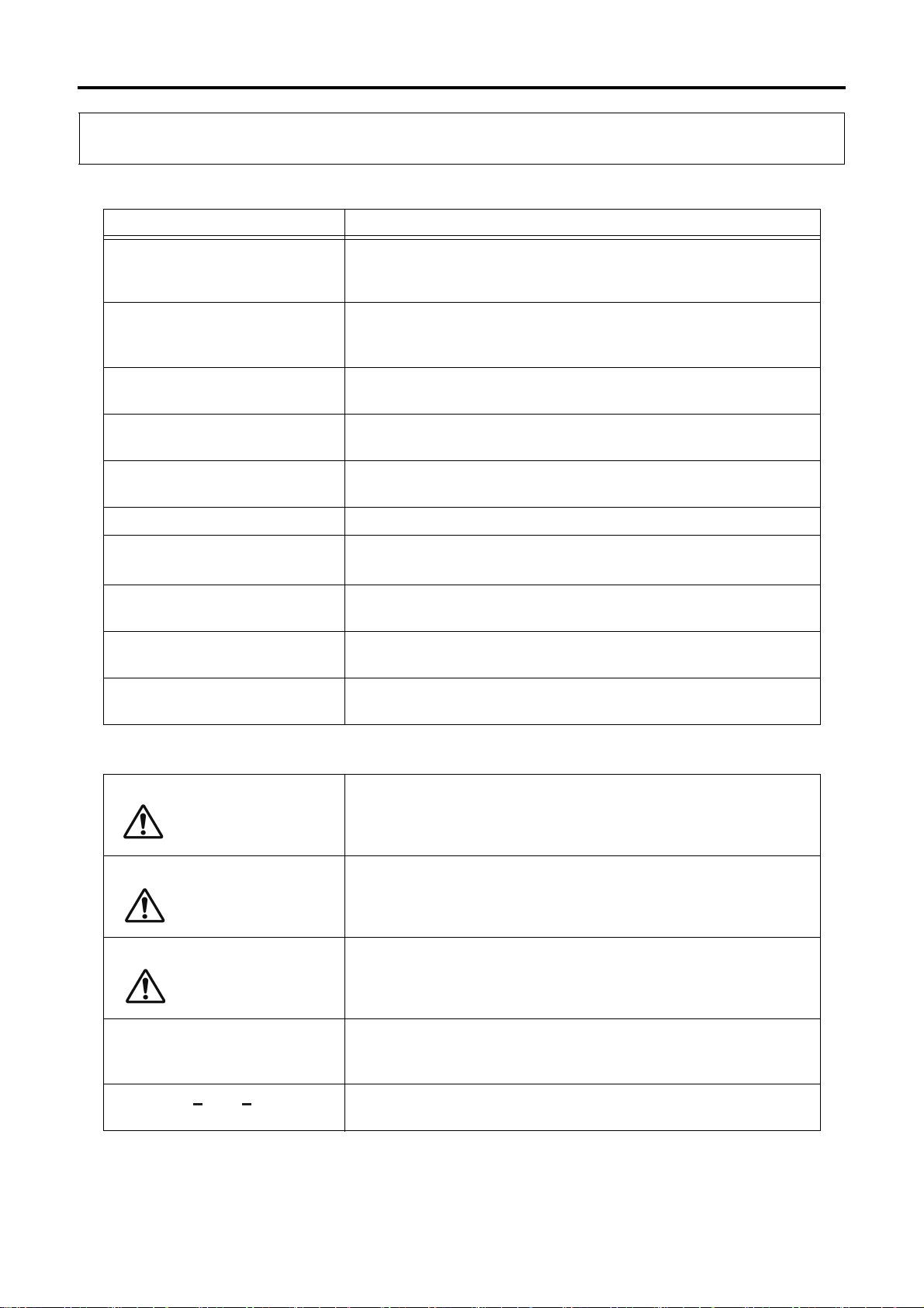
Manuals Belonging to This Machine
Name Description
Instruction Manual This manual includes the basic information (overview,
specifications) needed for operation, practical operating
procedures (operation), and troubleshooting procedures.
Periodic Maintenance Manual This manual explains the intervals for periodic maintenance and
work that is required for maintaining optimum performance of this
machine.
Peripheral Device Manual This manual describes the operating procedures for the peripheral
devices connected to the machine body.
Parts Manual This manual provides the machine component part names and
their order numbers.
Professional 6 Operation
Manual
Professional 6 M Code List This manual describes the M codes of Professional 6.
FANUC
Set of NC Manuals
Maintenance Manual (option) This manual describes the mechanisms of the machine and how to
Installation Manual (option) This manual describes the preparation, carry-in, and installation
Other manuals for options These manuals describe the operating procedures for the optional
This manual describes the operating procedures and various
functions of the controller (Professional 6).
These manuals describe the operating procedures for FANUC
equipment.
perform the maintenance and adjustment work.
procedures for setup of the machine.
devices.
Notation Used in This Manual
Indicates an imminent hazard which, if not avoided, will result in
death or serious injury.
Indicates a potential hazard which, if not avoided, will result in
death or serious injury.
NOTICE
29F25D-2006EN
Indicates a possible hazard which, if not avoided, may result in
minor or moderate injury.
Indicates a potential situation which, if not avoided, may result in
physical damage to the machine or adversely affect the work
environment.
Indicates supplemental information for appropriate and efficient
work or better understanding of the operation.

29F25D-2006EN

Contents
Chap. 1 Safety
1 Safety Precautions.................................................................................... 1-1
1.1 Operator Checks .......................................................................................................... 1-2
1.2 Work Environment Checks ........................................................................................... 1-2
1.3 Precautions for Potential Fire Hazards ......................................................................... 1-3
1.4 Confirmation of Machine Status ................................................................................... 1-4
1.5 Pre-operation Checks ................................................................................................... 1-5
1.6 Implementing Lock-out and Tag-out ............................................................................. 1-7
1.7 During Work ................................................................................................................. 1-8
1.8 Handling of Hazardous and Toxic Materials ............................................................... 1-11
2 Warning Labels....................................................................................... 1-12
2.1 Signal Word Definitions .............................................................................................. 1-12
2.2 Using Warning Labels ................................................................................................ 1-13
2.3 Information Contained in Warning Labels .................................................................. 1-14
2.3.1 Warning Labels with Warning Text ................................................................ 1-14
2.3.2 Warning Labels with Warning Marks Only .................................................... 1-14
2.4 Warning Label Locations ............................................................................................ 1-15
2.4.1 Area around Operator Door ........................................................................... 1-15
2.4.2 Area around Tool Magazine .......................................................................... 1-16
3 Safety Devices........................................................................................ 1-17
3.1 "Emergency Stop" Switch ........................................................................................... 1-17
3.1.1 "Emergency Stop" Switch Installation Location (Machine Body) ................... 1-18
3.1.2 "Emergency Stop" Switch Installation Location
(Large Capacity Tool Magazine) .................................................................. 1-19
3.2 Door Switch ................................................................................................................ 1-20
3.2.1 Door Switch Installation Location (Machine Body) ........................................ 1-20
3.2.2 Door Switch Installation Location
(Disk Type Tool Magazine 21-tool/40-tool) .................................................. 1-21
3.2.3 Door Switch Installation Location (Large Capacity Tool Magazine) .............. 1-22
4 Work Hazards ......................................................................................... 1-23
4.1 Area Surrounding Machine ......................................................................................... 1-23
4.2 Electrical System ........................................................................................................ 1-24
4.3 Parameters ................................................................................................................. 1-24
4.4 Inside the Machining Chamber ................................................................................... 1-24

Contents
4.5 Tool Magazine ............................................................................................................ 1-26
4.6 Cutting Fluid Supply Unit/Chip Disposal Device/
Cutting Fluid Temperature Controller/Dust Collector (Graphite Specifications) ......... 1-27
4.7 Temperature Controller .............................................................................................. 1-27
4.8 Hydraulic Unit ............................................................................................................. 1-28
4.9 Pneumatic Unit ........................................................................................................... 1-28
4.10 Splash Guard ............................................................................................................. 1-28
4.11 Other Peripheral Equipment ....................................................................................... 1-29
5 Occupational Health and Safety Management ....................................... 1-30
5.1 Safety Device Inspection ............................................................................................ 1-30
5.2 Noise .......................................................................................................................... 1-30
5.3 Personal Protective Equipment .................................................................................. 1-31
5.4 Disposal of Waste Products ....................................................................................... 1-32
5.4.1 Disposal of Waste Oil, Waste Fluids, and Waste Materials .......................... 1-32
5.4.2 Disposal of This Machine .............................................................................. 1-32
Chap. 2 Adjustment/Replacement
A Spindle Head
1 Overall View..............................................................................................A-1
1.1 Components of Spindle Head ...................................................................................... A-2
2 Adjustment of Switches ............................................................................A-5
2.1 Adjustment of Position Sensor ..................................................................................... A-5
B Feed Axis
1 Overall View..............................................................................................B-1
1.1 Components of Feed Axes ........................................................................................... B-2
2 Adjustment of Components ......................................................................B-4
2.1 Establishing the Reference Position ............................................................................. B-4
2.2 Adjusting the Reference Positions ............................................................................... B-6
2.2.1 Checking and Adjusting the X-Axis Reference Position .................................. B-8
2.2.2 Checking and Adjusting the Y-Axis Reference Position ................................ B-10
2.2.3 Checking and Adjusting the Z-Axis Reference Position ................................ B-13

Contents
2.2.4 Changing the Grid Shift Amount .................................................................... B-16
2.3 Backlash Measurement and Compensation ............................................................... B-18
2.4 Applying Pretension to Ball Screws ............................................................................ B-21
2.4.1 Removing the Servomotor ............................................................................. B-21
2.4.2 Adjusting the Pretension ............................................................................... B-24
2.4.3 Checking and Adjusting the Run-out of Ball Screws ..................................... B-26
C Rotary Table
1 Overall View..............................................................................................C-1
1.1 Components of Tilting and Rotary Axes ....................................................................... C-2
2 Adjustment of Components ......................................................................C-4
2.1 Establishing the Reference Position ............................................................................. C-4
2.2 Adjusting the Reference Positions ............................................................................... C-6
2.2.1 Checking and Adjusting the Reference Position of Tilting Axis (B-axis) ......... C-6
2.2.2 Checking and Adjusting the Reference Position of Rotary Axis (C-axis) ........ C-8
2.2.3 Changing the Grid Shift Amount .................................................................... C-10
3 Adjustment of Switches ..........................................................................C-12
3.1 Adjustment of Pressure Switch LS51/LS52 (Table Clamp/Unclamp) ......................... C-12
3.2 Adjustment of Pressure Switch LS151/LS152
(Additional 1st Axis Clamp/Unclamp) ......................................................................... C-14
3.3 Setting of Pressure Switch Detection Pressure .......................................................... C-16
D1 Disk Type Tool Magazine (21-tool)
1 Overall View............................................................................................D1-1
1.1 Components of Disk Type Tool Magazine ................................................................. D1-2
1.2 Tool Magazine Operation ........................................................................................... D1-4
2 Adjustment of Components ....................................................................D1-8
2.1 Establishing the Reference Position ........................................................................... D1-8
2.2 Adjusting the Reference Positions ........................................................................... D1-10
2.2.1 Checking and Adjusting the Reference Position of Tool Magazine Axis ..... D1-10
2.2.2 Changing the Grid Shift Amount .................................................................. D1-13
2.3 Adjustment of 2nd Reference Position (Tool Change Position) ............................... D1-14
2.3.1 Centering Adjustment (Adjustment of X-Axis/Z-Axis Direction) ................... D1-14
2.3.2 Adjustment of Tool Magazine Position Relative to Spindle Head ............... D1-19

Contents
2.4 Adjustment of ATC Shutter Operation Speed .......................................................... D1-22
3 Adjustment of Switches ........................................................................D1-24
3.1 Adjustment of Proximity Switch LS99
(Tool Magazine Tool Presence Confirmation) .......................................................... D1-24
3.2 Adjustment of Proximity Switch LS747/LS748 (ATC Shutter Close/Open) .............. D1-26
D2 Disk Type Tool Magazine (40-tool)
1 Overall View............................................................................................D2-1
1.1 Components of Disk Type Tool Magazine ................................................................. D2-2
1.2 Tool Magazine Operation ........................................................................................... D2-6
2 Adjustment of Components ..................................................................D2-12
2.1 Establishing the Reference Position ......................................................................... D2-12
2.2 Adjusting the Reference Positions ........................................................................... D2-15
2.2.1 Checking and Adjusting the Reference Position of Tool Magazine Axis ..... D2-15
2.2.2 Changing the Grid Shift Amount .................................................................. D2-17
2.3 Adjustment of 2nd Reference Position (Tool Change Position) ............................... D2-18
2.3.1 Centering Adjustment (Adjustment of X-Axis/Z-Axis Direction) ................... D2-18
2.3.2 Adjustment of Tool Magazine Position Relative to Spindle Head ............... D2-23
2.4 Adjustment of ATC Shutter Operation Speed .......................................................... D2-26
2.5 Adjustment of Shifter Operation Speed .................................................................... D2-28
3 Adjustment of Switches ........................................................................D2-30
3.1 Adjustment of Proximity Switch LS99
(Tool Magazine Tool Presence Confirmation) .......................................................... D2-30
3.2 Adjustment of Limit Switch LS679/LS680 (Shifter Advance/Retract) ....................... D2-32
3.3 Adjustment of Proximity Switch LS747/LS748 (ATC Shutter Close/Open) .............. D2-36
3.4 Adjustment of Limit Switch LS760/LS761 (Shifter Lower/Raise) .............................. D2-38
3.5 Adjustment of Proximity Switch LS1971/LS1972 (Shifter Tool Clamp/Unclamp) ..... D2-43
3.6 Adjustment of Proximity Switch LS2715
(Lower Magazine Tool Presence Confirmation) ....................................................... D2-46
E1 Temperature Controller
1 Overall View............................................................................................E1-1
1.1 Components of Temperature Controller ..................................................................... E1-2
1.2 Cooling Oil Piping ....................................................................................................... E1-3

Contents
E2 Oil Air Supply Device
1 Overall View............................................................................................E2-1
1.1 Components of Oil Air Supply Device ........................................................................ E2-2
1.2 Oil/Air Piping ............................................................................................................... E2-3
F1 Hydraulic Unit
1 Overall View............................................................................................ F1-1
1.1 Components of Hydraulic Unit .................................................................................... F1-2
1.2 Hydraulic Piping ......................................................................................................... F1-3
2 Adjustment of Components ....................................................................F1-6
2.1 Pressure Adjustment of Hydraulic Unit ....................................................................... F1-6
F2 Pneumatic Unit
1 Overall View............................................................................................ F2-1
1.1 Components of Pneumatic Unit .................................................................................. F2-2
2 Adjustment of Switches ..........................................................................F2-6
2.1 Setting Confirmation of Pressure Switch LS905 (Air Pressure Switch) ...................... F2-6
G1 Chip Disposal Device/Cutting Fluid Supply Unit
1 Overall View........................................................................................... G1-1
1.1 Components of Chip Disposal Device/Cutting Fluid Supply Unit ............................... G1-3
G2 Dust Collector
1 Overall View........................................................................................... G2-1
1.1 Components of Dust Collector ................................................................................... G2-2
1.2 Dust Collection Route ................................................................................................. G2-3
H Safety Devices
1 Overall View..............................................................................................H-1
1.1 Electrical Safety Devices .............................................................................................. H-1
1.2 Mechanical Safety Devices .......................................................................................... H-2

Contents
2 Safety Device Inspection ..........................................................................H-3
2.1 Inspection of "Main Power" Switch ............................................................................... H-4
2.2 Inspection of "Emergency Stop" Switch ....................................................................... H-5
2.3 Inspection of Operator Door Mechanism ...................................................................... H-6
2.3.1 Inspection of [DOOR LOCK RELEASE] switch ............................................... H-6
2.3.2 Inspection of Door Switch LS912 (Operator Door Interlock) Signal ................ H-7
2.3.3 Inspection of Operator Door Lock Operation ................................................... H-8
2.4 Inspection of Tool Magazine Door Mechanism .......................................................... H-10
2.4.1 Inspection of [MAGAZINE DOOR LOCK RELEASE] button ......................... H-10
2.4.2 Inspection of Door Switch LS942 (Tool Magazine Door) Signal ................... H-11
2.4.3 Inspection of Tool Magazine Door Lock Operation ....................................... H-12
2.5 Inspection of Covers and Doors ................................................................................. H-13
3 Adjustment of Switches ..........................................................................H-14
3.1 Adjustment of Door Switch LS912 (Operator Door Interlock) ..................................... H-14
3.2 Adjustment of Door Switch LS942 (Tool Magazine Door) .......................................... H-16

Chap. 1 Safety
1 Safety Precautions.................................................................................... 1-1
1.1 Operator Checks ........................................................................................................... 1-2
11.2 Work Environment Checks............................................................................................ 1-2
1.3 Precautions for Potential Fire Hazards.......................................................................... 1-3
1.4 Confirmation of Machine Status .................................................................................... 1-4
1.5 Pre-operation Checks.................................................................................................... 1-5
1.6 Implementing Lock-out and Tag-out.............................................................................. 1-7
1.7 During Work .................................................................................................................. 1-8
11.8 Handling of Hazardous and Toxic Materials................................................................ 1-11
2 Warning Labels....................................................................................... 1-12
2.1 Signal Word Definitions............................................................................................... 1-12
2.2 Using Warning Labels ................................................................................................. 1-13
2.3 Information Contained in Warning Labels ................................................................... 1-14
2.3.1 Warning Labels with Warning Text................................................................. 1-14
2.3.2 Warning Labels with Warning Marks Only ..................................................... 1-14
1
Safety
2.4 Warning Label Locations............................................................................................. 1-15
2.4.1 Area around Operator Door............................................................................ 1-15
2.4.2 Area around Tool Magazine........................................................................... 1-16
3 Safety Devices........................................................................................ 1-17
3.1 "Emergency Stop" Switch............................................................................................ 1-17
3.1.1 "Emergency Stop" Switch Installation Location (Machine Body).................... 1-18
3.1.2 "Emergency Stop" Switch Installation Location
(Large Capacity Tool Magazine) .................................................................... 1-19
3.2 Door Switch................................................................................................................. 1-20
3.2.1 Door Switch Installation Location (Machine Body)......................................... 1-20
3.2.2 Door Switch Installation Location
(Disk Type Tool Magazine 21-tool/40-tool) .................................................... 1-21
3.2.3 Door Switch Installation Location (Large Capacity Tool Magazine)............... 1-22
4 Work Hazards ......................................................................................... 1-23
4.1 Area Surrounding Machine.......................................................................................... 1-23
4.2 Electrical System......................................................................................................... 1-24
4.3 Parameters.................................................................................................................. 1-24

4.4 Inside the Machining Chamber.................................................................................... 1-24
4.5 Tool Magazine............................................................................................................. 1-26
4.6 Cutting Fluid Supply Unit/Chip Disposal Device/
Cutting Fluid Temperature Controller/Dust Collector (Graphite Specifications)........... 1-27
4.7 Temperature Controller ............................................................................................... 1-27
4.8 Hydraulic Unit .............................................................................................................. 1-28
4.9 Pneumatic Unit............................................................................................................ 1-28
4.10 Splash Guard .............................................................................................................. 1-28
4.11 Other Peripheral Equipment........................................................................................ 1-29
5 Occupational Health and Safety Management ....................................... 1-30
5.1 Safety Device Inspection............................................................................................. 1-30
5.2 Noise ........................................................................................................................... 1-30
5.3 Personal Protective Equipment................................................................................... 1-31
5.4 Disposal of Waste Products ........................................................................................ 1-32
5.4.1 Disposal of Waste Oil, Waste Fluids, and Waste Materials ........................... 1-32
5.4.2 Disposal of This Machine ............................................................................... 1-32

1 Safety Precautions
1 Safety Precautions
• Disregarding the specific instructions or precautions included in this manual may result in
serious injury or death to the operators or surrounding workers, or damage to the machine.
• Never disable or remove any safety device. Operating the machine while the safety devices are
disabled may result in serious injury, death, or damage to the machine.
• Observe the safety precautions provided in this manual at all times and fully implement safety
measures.
• Inspect and maintain the machine regularly to keep it in optimum operating condition. Do not run
the machine if it shows any signs of abnormal operation.
• The keys (release key for door switch, machine controller panel key, etc.) which are not
necessary for regular operation and maintenance must be removed from the machine and
managed by supervising personnel.
• The lubricating oil, cutting fluid, and other chemical substances used with the machine must be
managed by supervising personnel.
1
Safety
• Workpiece materials such as magnesium and titanium may cause a fire if mishandled, so be
particularly careful when machining workpieces and handling cutting chips made from these
types of materials.
29F25D-2006EN
1-1
1 Safety Precautions
1.1 Operator Checks
1.1 Operator Checks
• Only qualified personnel who have adequate mechanical and technical knowledge are allowed
to operate and maintain the machine.
• Only qualified electrical engineers may perform electrical work.
• Only qualified personnel may use a crane or forklift.
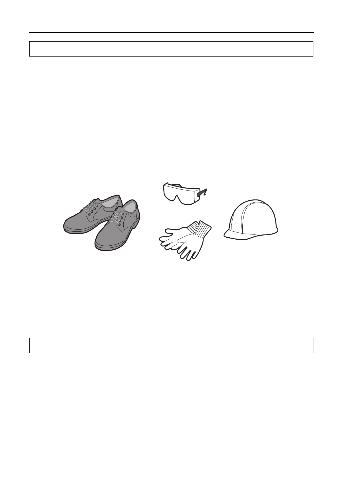
• Wear suitable work clothes whenever operating or maintaining the machine. Do not operate the
machine while wearing loose-fitting clothes, a necktie, jewelry, or any other clothing or objects
which may become entangled with the moving parts of the machine.
• Tie up long hair, and wear a cap.
• Wear safety glasses, safety shoes, safety cap (including safety helmet), and safety gloves as
needed.
• Protective gear should be worn to protect hearing when excessive noise may be generated
during operation or maintenance.
• Never operate any machinery while under the influence of alcohol or drugs.
• The operator should be in proper physical condition. If the operator suffers from a condition that
impairs judgment, it may result in serious injury or death.
1.2 Work Environment Checks
• Make sure the machine and surrounding area are fully lighted.
• Make sure the machine and surrounding area are tidy and clean at all times.
• Clean up any oil, cutting fluid, or chips scattered around the machine.
• When performing work at high locations, use a stable footstool or stepladder.
• Keep all flammable substances away from the work area.
• Maintain adequate working space.
1-2
29F25D-2006EN

1 Safety Precautions
1.3 Precautions for Potential Fire Hazards
1.3 Precautions for Potential Fire Hazards
Use the machine by following the precautions below to protect the machine equipment, plant, and
surrounding environment from the danger of fire and to ensure the safety of operators.
1 When using cutting fluid, be sure to use a water-soluble cutting fluid (type A1).
There is no fire hazard when using water-soluble cutting fluids (except when using them with
special materials).
1
2 Oil-based cutting fluids present a potential fire hazard.
If an oil-based cutting fluid must be used due to unavoidable circumstances, be sure to
observe the precautions below.
• Do not run the machine in an unmanned operation mode.
• Install the proper fire-extinguishing equipment near the machine.
• Provide alarm devices to detect a fire, automatic fire-extinguishing devices, and other
equipment to the greatest extent possible.
• Do not create situations which may potentially start a fire.
• Machine under the proper cutting conditions.
• Perform proper tool management to prevent the occurrence of abnormal frictional heat
and sparks.
• Do not allow chips to accumulate in the machining chamber.
• Check that a constant and full supply of cutting fluid is provided.
• Always clean up and organize the area around the machine, and do not place
flammable objects in the area.
Safety
3 Precautions for machining of flammable solids, resins, wood, and other flammable materials.
When machining flammable solids or other special materials, be sure to fully implement safety
measures after gaining a thorough understanding of the material properties. Be sure to also
pay careful attention to safety when machining resins, wood, and other materials.
When machining materials that generate dust and powder, be sure to provide equipment that
takes into account the danger of a dust explosion for certain material types.
4 Precautions for machining while blowing air.
Because air blowing has weak cooling performance, the chips that spray and fly out in the
surrounding area are extremely hot. Do not place flammable objects in the machining
chamber or in the area surrounding the machine.
29F25D-2006EN
1-3

1 Safety Precautions
1.4 Confirmation of Machine Status
1.4 Confirmation of Machine Status
• Machine inspections and maintenance must be performed regularly to maintain optimum
machining accuracy and long-term performance, and increase machine operating efficiency.
• Confirm that all safety devices are functioning normally.
• Make sure the operator knows the location of the "Emergency Stop" switches to enable easy
access in the event of an abnormal or dangerous situation (Refer to 3.1 "Emergency Stop"
Switch).
• Check for any loose, damaged, or worn parts on the machine. Operating the machine in a
condition in which any of the parts has an abnormality may cause abnormal noises or damage to
the machine.
• Check for any damaged piping or wiring. Operating the machine with the piping or wiring left
damaged may cause oil leakage, electrical shock, or fire.
• Use the most appropriate cutting tool, tool holder, retention knob, and workpiece, and make sure
that they are all secured firmly in place. Otherwise, the workpiece may fall or the tool may fly out,
and this may result in damage to the machine, serious injury, or death.
• Check that the tool numbers are registered correctly. Otherwise, the spindle may rotate at a
speed outside the allowable range, the tool may fly out, and this may result in damage to the
machine, serious injury, or death.
1-4
29F25D-2006EN

1 Safety Precautions
1.5 Pre-operation Checks
1.5 Pre-operation Checks
• Be sure that you fully understand the work procedures and precautions before operating and
maintaining the machine. Never operate any machinery if you are unsure about any points.
• Check that the clothes you are wearing are suitable for operation.
• Perform periodic maintenance.
• Confirm that all safety devices are functioning properly before operating and maintaining the
machine.
• Periodically back up the parameters when the machine was shipped and the program and offset
data that have been prepared by the customer. Makino is not liable for any program or offset
data that is corrupted or lost.
• Makino does not accept responsibility for any trouble caused by apparatus or programs
prepared by the customers, such as damage to workpieces or the machine.
• For details about replacement parts, contact your Makino service representative. Use of
improper parts may result in reduced machine performance or safety, damage to the machine, or
operator injuries.
1
Safety
• Before entering inside the machine to perform work, be sure to confirm the escape procedure in
the event that you inadvertently become shut inside the machine.
• Perform the lock-out and tag-out procedures.
• Make sure the operator knows the location of the "Emergency Stop" switches for each device so
that they can be easily operated in the event of an abnormal or dangerous situation.
• Be sure to observe the information on the warning labels. Contact your Makino service
representative if a warning label comes off or becomes illegible.
• When handling a hazardous or toxic material (oils, cutting fluids, and other chemical
substances), obtain the safety data sheet (SDS), and follow the instructions. The safety data
sheet (SDS) contains information about the safe handling of hazardous and toxic materials, and
emergency measures.
29F25D-2006EN
1-5

1 Safety Precautions
1.5 Pre-operation Checks
• For the graphite specifications, do not let the dust collector collect anything other than graphite
dust. Failure to observe this precaution may result in a dust explosion. Also, it may damage the
filter or cause other malfunctions.
• For the graphite specifications, observe the following precautions to prevent health problems
related to the inhalation of graphite dust.
• After machining the workpieces, wait for the dust collector to remove airborne dust particles
before opening the operator door. If you open the operator door immediately after
machining, the airborne dust will disperse throughout the machining room.
• Wear a high-performance dust-proof mask when doing the following (particle collection
efficiency of 99.9% or more is recommended).
• Opening and closing the operator door
• Performing an operation with the operator door open
• Replacing a tool in the tool magazine
• Handling dust
• Do not remove the dust car and chip bucket while the dust collector is operating. Otherwise,
dust will disperse in the surrounding area.
1-6
29F25D-2006EN
1 Safety Precautions
1.6 Implementing Lock-out and Tag-out
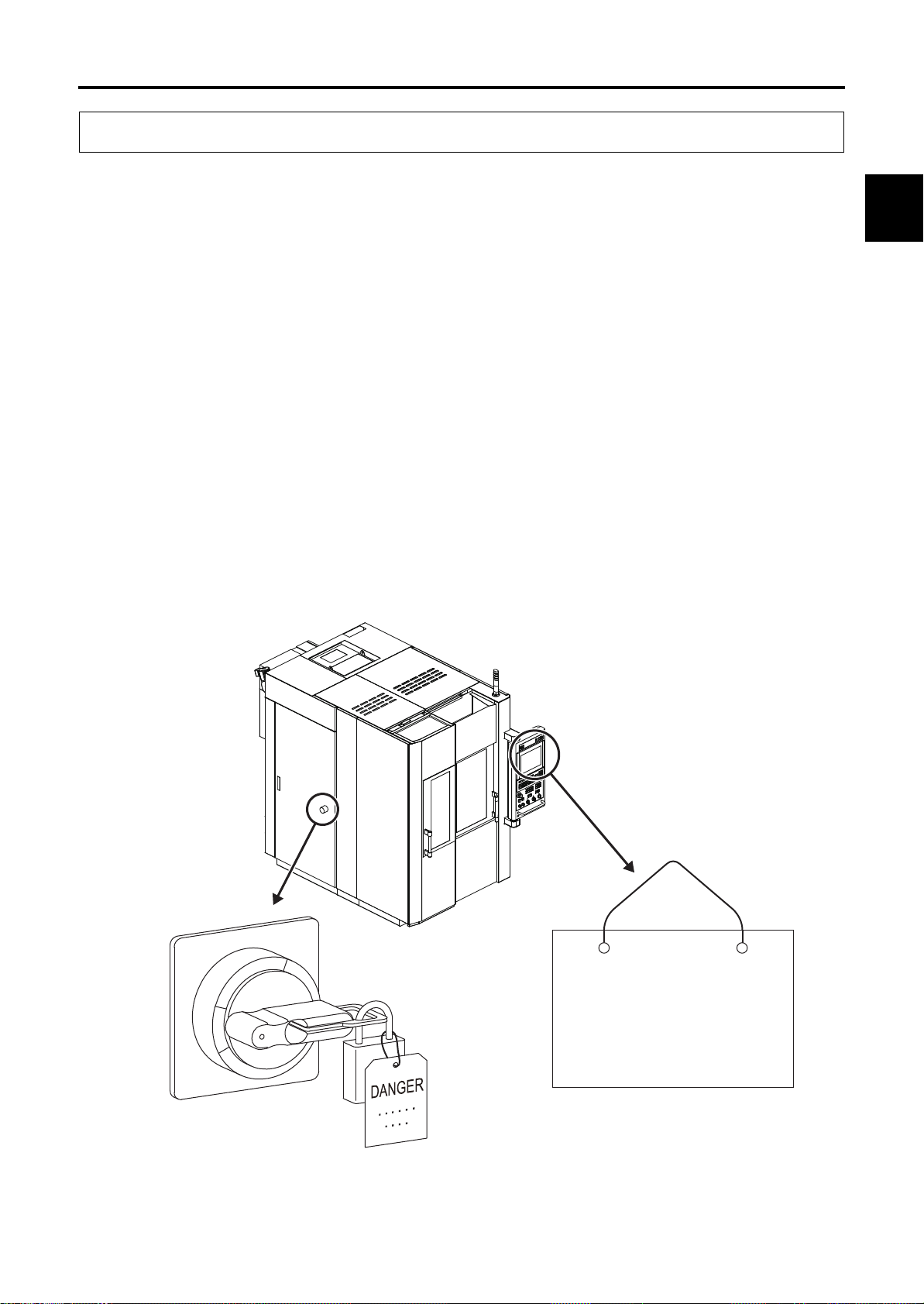
1.6 Implementing Lock-out and Tag-out
Lock-out consists of shutting down the power source to the machine or devices and locking it.
Example: Set the main power switch to the "OFF" position and secure it using a padlock or a
lockout device such as a cover.
Tag-out consists of placing a warning tag to prevent anyone from turning ON the power.
Example: Place a "Do Not Operate" or "Under Maintenance" sign with the operator's name and
department and indicating that machine operation is prohibited on the main power switch and
main operation panel.
Lock-out/tag-out should be performed to prevent inadvertent operation and ensure operator safety.
• Performing lock-out/tag-out alone does not completely ensure operator safety. The operator
must read and thoroughly understand the work procedures and safety precautions, and always
be aware of potential hazards.
Each operator should perform lock-out or tag-out by himself or herself. Perform this procedure before
starting the work, and release the lock and remove warning tag yourself after finishing work. Never
release a lock and remove a sign without confirming with the operator or without the presence of the
operator himself or herself.
Be sure to clearly define and implement the lock-out and tag-out procedures of your company.
1
Safety
29F25D-2006EN
OFF
OFF
ON
ON
Figure 1-1 Implementing Lock-out and Tag-out
DANGER
DANGER
Under Maintenance/
Under Maintenance/
Inspection
Inspection
Operator's Name: xxxxx
Operator's Name: xxxxx
Department: xxxxx
Department: xxxxx
1-7

1 Safety Precautions
1.7 During Work
1.7 During Work
• Turn OFF the power before performing maintenance of the machine. When work must be
performed with the machine power ON, confirm that all machine operations are completely
stopped. Check that any residual energy in the machine is completely discharged.
• Never go near the moving parts of the machine. If you must approach moving parts to perform
maintenance, be sure to take adequate safety precautions. Inadequate attention to safety may
result in death or another serious accident.
• Always keep the doors and covers closed during operation. If you must work with the doors and
covers open, be sure to take adequate safety precautions. Inadequate attention to safety may
result in death or another serious accident.
• If an operator gets trapped inside the machine, press the "Emergency Stop" switch regardless of
whether the machine power is ON or OFF.
• If the machine is stopped by a power failure or power supply fault, turn OFF the machine power.
If the power is not turned OFF, the machine may start operating unexpectedly when the power is
restored, and this may result in serious injury, death, or damage to the machine.
• If the machine is stopped by a power failure or power supply fault, check that the parameter,
program, and offset data have not been corrupted. The machine may be damaged if it is
operated using corrupted data.
• Be aware of the movement range of the machine and auxiliary components (each axis stroke,
rotation range, etc.), and keep all body parts clear of moving components.
• When two or more people are required for maintenance work, be sure to maintain clear
communication at all times to ensure operator safety. When performing work, be ready to press
the "Emergency Stop" switch at any time.
• Be sure to always pay attention to the safety precautions listed on the warning labels affixed to
the machine (Refer to 2 Warning Labels2 Warning Labels).
• Do not operate the switches or change the circuits except for adjustment purposes. In particular,
operating the machine with the interlock(s) or other safety devices or functions disabled is
extremely dangerous and may result in death or damage to the machine.
• If a circuit or other component needs to be changed for adjustment purposes, be sure to return it
to the original setting after adjustment is completed.
• The optimum values for the NC parameters and machine parameters are set when the machine
is shipped. Do not change any parameter setting unless it is described in the manual. Also, be
sure that you fully understand the function of a parameter before attempting to change the
parameter setting, and return the parameter to its original setting after the work is completed. If
you try to operate the machine without the proper settings, the machine may operate
unexpectedly, and this may result in serious injury, death, or damage to the machine.
• If the memory clear operation needs to be performed, be sure to contact your Makino service
representative beforehand.
• If an alarm is triggered, eliminate the cause of the alarm using the appropriate procedure. If the
remedy procedure is unclear, contact your Makino service representative.
• Never climb onto the covers. This may deform the covers or result in injury.
1-8
29F25D-2006EN

1 Safety Precautions
1.7 During Work
• When using a stepladder or stool, it should be sturdy, safe, and have anti-slip surfaces.
• If any oils or cutting fluids get into your eyes, body, or on your skin surface, they may cause
severe health problems. Wear safety gloves, mask, safety glasses, and other safety equipment.
• Wear safety gloves whenever handling chips, tools, and workpieces.
• Protective gear should be worn to protect hearing when excessive noise may be generated
during operation or maintenance.
• If lubricating oil, grease, cutting fluid, or other substances are spilled on the floor, it may result in
slippage, causing injury. Wipe up any spilled fluids as soon as possible.
• Never touch a switch, button, or key while your hands are wet. Failure to observe this precaution
may result in electric shock.
• Some devices (motors, lighting equipment, valves, etc.) may become very hot while the machine
is operating and remain hot soon after the power is turned OFF, so be careful to avoid burns.
• Do not subject the machine to sudden impact or jolts. This may cause the machine to perform an
unexpected motion or result in damage to the machine.
• Do not use the machine for operation outside the specifications or exceeding the performance
range. This may cause the machine to perform an unexpected motion or result in serious injury,
death, or damage to the machine.
• Use the most appropriate cutting tool, tool holder, retention knob, and workpiece, and make sure
that they are all secured firmly in place. Otherwise, the workpiece may fall or the tool may fly out,
and this may result in damage to the machine, serious injury, or death.
1
Safety
• Be careful that you do not leave objects such as tools or jigs inside the machine.
• Do not place the tools, workpiece, or other parts on an unstable location.
• When a lifting sling or attachment is necessary, verify that it is strong enough to support the
weight of the parts. Confirm that no one is close to the machine and the parts are well balanced,
and be careful not to hit to the machine.
• Never go under a load that is being lifted. While transferring the hoisted load, constantly pay
careful attention to the hoisted load during the operation.
• Check that the tool numbers are registered correctly. Otherwise, the spindle may rotate at a
speed outside the allowable range, the tool may fly out, and this may result in damage to the
machine, serious injury, or death.
• Never insert hands or feet into the chip conveyor. They may be pulled in, and this may result in
death or another serious accident.
29F25D-2006EN
1-9

1 Safety Precautions
1.7 During Work
• For the graphite specifications, observe the following precautions to prevent health problems
related to the inhalation of graphite dust.
• After machining the workpieces, wait for the dust collector to remove airborne dust particles
before opening the operator door. If you open the operator door immediately after
machining, the airborne dust will disperse throughout the machining room.
• Wear a high-performance dust-proof mask when doing the following (particle collection
efficiency of 99.9% or more is recommended).
• Opening and closing the operator door
• Performing an operation with the operator door open
• Replacing a tool in the tool magazine
• Handling dust
• Do not remove the dust car and chip bucket while the dust collector is operating. Otherwise,
dust will disperse in the surrounding area.
1-10
29F25D-2006EN

1 Safety Precautions
1.8 Handling of Hazardous and Toxic Materials
1.8 Handling of Hazardous and Toxic Materials
Handlers of hazardous and toxic materials (such as oils and cutting fluid) must receive information,
education, and training in accordance with the stipulations in JIS Z 7253 (revised March 2012)/
ISO 11014: 2009.
Particular attention must be paid to the following points.
• Be sure that there is adequate ventilation in areas where hazardous and toxic materials are
used.
• Hazardous and toxic materials must be handled and stored based on the handling procedures
recommended by the manufacturer.
• Identify hazardous and toxic materials by affixing labels to their containers.
• Assign a person in charge to handle the hazardous and toxic materials, and provide education
and training in emergency response procedures and handling procedures.
• Before handling any hazardous or toxic material, be sure to check the safety data sheet (SDS).
The safety data sheet (SDS) contains detailed information on health and safety hazards, safe
handling procedures, and responses to emergency situations.
1
Safety
29F25D-2006EN
1-11
2 Warning Labels
DANGER
WARNING
CAUTION
2.1 Signal Word Definitions
2 Warning Labels
Warning labels are affixed to machine parts that are potentially hazardous to warn operators about the
hazard and its level of danger and ensure the safety of operators.
The warning labels include symbols to indicate the source of the danger, signal words to indicate the
level of danger, and warning text to describe how to prevent the danger. When working at a location
where a warning label is affixed, make sure that you fully understand the warning label information and
definitions and follow the warning text that is provided. Failure to observe the information in the
warning labels may result in death or another serious accident or damage to the machine.
2.1 Signal Word Definitions
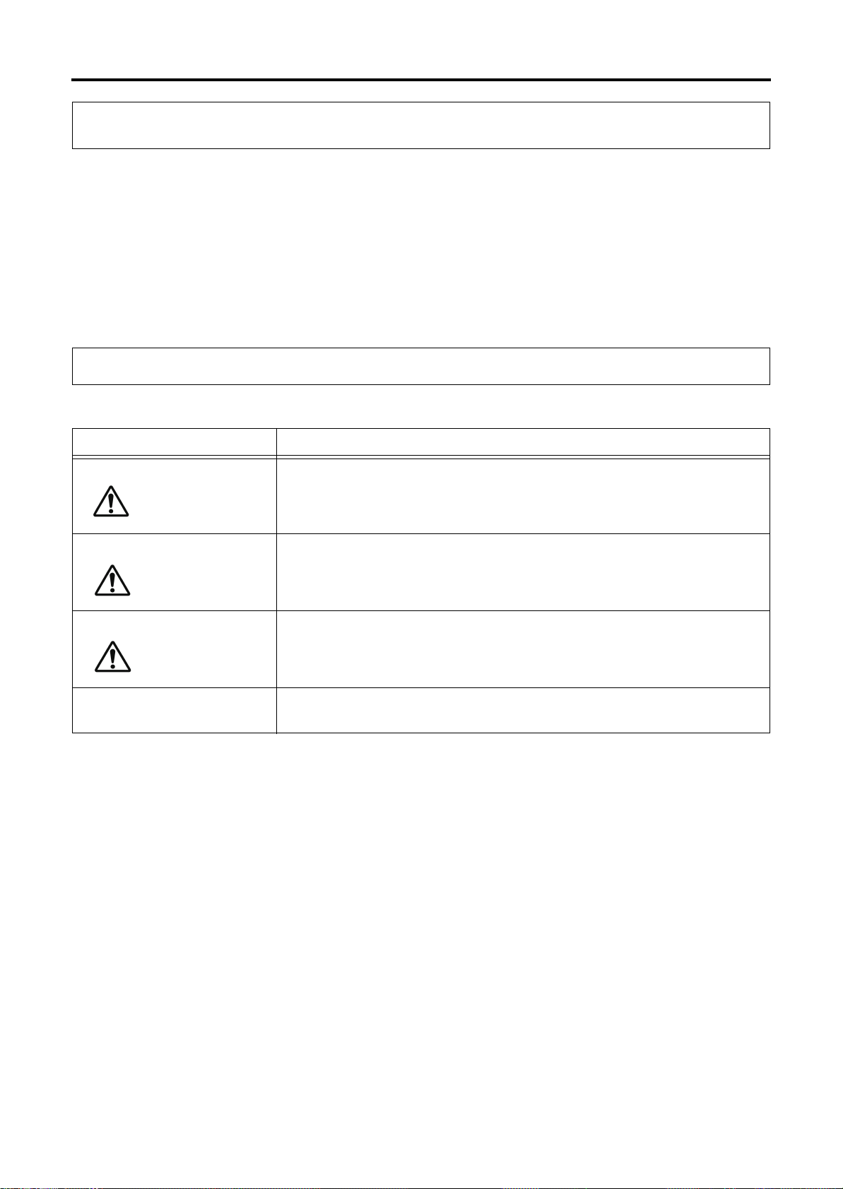
Signal words are divided into four classes based on the degree of expected risk.
Signal Word Description
NOTICE
Indicates an imminent hazard which, if not avoided, will result in death or
serious injury.
Indicates a potential hazard which, if not avoided, will result in death or
serious injury.
Indicates a possible hazard which, if not avoided, may result in minor or
moderate injury.
Indicates a potential situation which, if not avoided, may result in physical
damage to the machine or adversely affect the work environment.
1-12
29F25D-2006EN

2.2 Using Warning Labels
• Do not cover up or peel off the warning labels.
2 Warning Labels
2.2 Using Warning Labels
• Confirm that the operators and maintenance personnel are familiar with the language on the
labels. If labels in other languages are required, contact your Makino service representative.
• Check that all the information in the warning label is legible. If any portion of the warning text or
symbol is not visible, clean by wiping with a soft cloth dipped in water or household cleanser. Do
not use organic solvents or gasoline. These may damage the surface of the warning label.
• Replace the warning label if the information in the warning label is no longer visible. To obtain
new warning labels, contact your Makino service representative.
• If a part is replaced where a warning label was affixed, obtain a new warning label and affix it at
the same position as before on the new part. To obtain new warning labels, contact your Makino
service representative.
1
Safety
29F25D-2006EN
1-13
2 Warning Labels
DANGER
DANGER
DANGER
CAUTIONCAUTION
2.3 Information Contained in Warning Labels
2.3 Information Contained in Warning Labels
The two types of warning labels are shown below.
• Labels with warning text and a warning mark
• Labels with a warning mark only
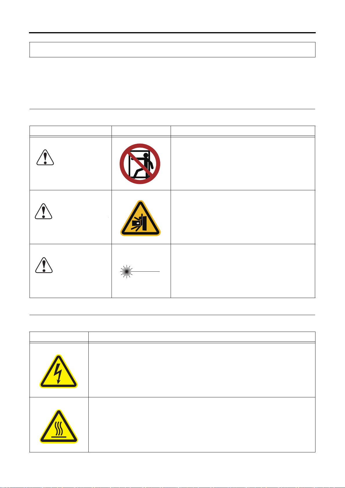
2.3.1 Warning Labels with Warning Text
Signal Word Symbol Description
This warning label is affixed to areas where entry is
prohibited.
This warning label is affixed to areas where there is a
risk of getting pressed, being sucked in, stabbed, or
falling down, resulting in a serious injury, accident, or
death.
Maximum output 1mW, semiconductor laser
Class 2 laser product
Do not stare into the beam.
2.3.2 Warning Labels with Warning Marks Only
Symbol Description
This warning label is affixed to parts where touching the internal high-voltage
components may result in electrical shock.
Workers who are not qualified electrical engineers must not access the parts where
this warning label is affixed.
1-14
This warning label is affixed to parts that may become extremely hot.
Do not touch parts where this warning label is affixed. Be particularly careful
immediately after operation because these parts are extremely hot at this time.
29F25D-2006EN
 Loading...