

Page 1

Original instructions
29F24D-2006EN
Page 2

Page 3

English
This manual should only be used by skilled maintenance
personnel.
Japanese
Albanian
Bosnian
Brazilian
Portuguese
Bulgarian
Chinese
Croatian
Czech
Danish
このマニュアルは訓練された保守要員がご使用ください。
Ky manual duhet të përdoret vetëm nga personeli I trajnuar
i mirëmbajtjes.
Ovo uputstvo bi trebalo koristiti samo osoblje obučeno za
održavanje.
Este manual apenas deve ser utilizado por técnicos de
manutenção qualificados.
За използване само от специално обучен персонал за
поддръжка.
本手册仅供已经培训的维护人员使用。
Ovaj priručnik namijenjen je samo obučenom osoblju za
održavanje.
Tato příručka může sloužit k použití pouze pro školený
personál údržby.
Denne manual må kun anvendes af specielt uddannet
servicepersonale.
Estonian
German
Hungarian
Indonesian
Dutch
Finnish
French
Greek
Italian
Dit handboek mag enkel door speciaal opgeleid
onderhoudspersoneel gebruikt worden.
Manuaal on mõeldud kasutamiseks ainult vastavate
oskustega hoolduspersonalile.
Vain koulutetut huoltohenkilöt saavat käyttää tätä
ohjekirjaa.
Ce manuel ne doit être utilisé que par du personnel de
maintenance compétent.
Dieses Handbuch darf nur duch speziell ausgebildetes
Wartungspersonal verwendet werden.
Το παρόν εγχειρίδιο πρέπει να χρησιμοποιείται από ειδικά
εκπαιδευμένο προσωπικό συντήρησης.
Ezt a kézikönyvet csak szakképzett karbantartó
személyzet használhatja.
Manual ini harus digunakan hanya oleh petugas
pemeliharaan yang berketerampilan.
Il presente manuale deve essere utilizzato solo da parte
del personale di manutenzione appositamente addestrato.
Korean
이 작업지도서는 기술이 능수한 정비인원이 사용해
주십시요
Page 4

Latv
ian
Šo rokasgrāmatu drīkst izmantot tikai kvalificēts tehniskās
apkopes personāls.
thuanian
Li
acedonian
M
alaysian
M
orwegian
N
P
olish
P
ortuguese
R
omanian
ssian
Ru
bian (cyr)
Ser
Šį vadovą turėtų naudoti tik kompetentingi techninės
priežiūros darbuotojai.
Овој прирачник треба да го користи само квалификуван
персонал за одржување.
Manual ini hendaklah digunakan oleh kakitangan
penyenggaraan yang mahir sahaja.
Denne håndboken skal kun brukes av autoriserte
reparatører.
Ten podręcznik jest przeznaczony do użytku wyłącznie
przez odpowiednio przeszkolony personel konserwacyjny.
Este manual apenas pode ser utilizado por técnicos de
manutenção qualificados.
Acest manual trebuie utilizat numai de personal de
întreţinere calificat.
Это руководство предназначено только для
квалифицированного обслуживающего персонала.
Ово упутство би требало да користи само особље
обучено за одржавање.
erbian (lat)
S
Sl
ovak
lovenian
S
S
panish
Sw
edish
hai
T
Tu
rkish
inian
Ukra
etnamese
Vi
Ovo uputstvo bi trebalo da koristi samo osoblje obučeno za
održavanje.
Príručku môže používať len špeciálne vyškolený personál
údržby.
Ta p ri ro čnik naj bi uporabljalo le osebje, usposobljeno za
vzdrževalna dela.
Este manual sólo puede utilizarlo personal de
mantenimiento especialmente cualificado.
Denna handbok får endast användas av speciellt utbildad
underhållspersonal.
Bu kullanım kılavuzu sadece özel eğitim almış uzman
bakım personeli tarafından kullanılmalıdır.
Ця настанова призначена лише для кваліфікованого
обслуговуючого персоналу.
Tài liệu hướng dẫn này chỉ nên sử dụng bởi nhân viên bảo
trì lành nghề.
Page 5

Important Information
General
• Do not attempt to modify the machine.
• Operation, maintenance, and inspection of this machine must be performed by staff who have
received technical training for the machine, training in machine hazards and their prevention,
and safety training.
• Observe the laws, regulations, and other rules of the relevant national and local administrative
agencies.
• This machine, including technical data and software, may be subject to the Japanese Foreign
Exchange and Foreign Trade Law.
Prior to any resale, transfer or re-export of controlled items, contact Makino to obtain any
required authorization or approval.
• The specifications and design are subject to change without prior notice.
This Manual
• This manual is prepared for usage by experienced operators. For this reason, it does not include
safety precautions for operators who do not have mechanical or technical knowledge of machine
operation, programming, and maintenance.
• If the machine is operated by persons who are not native speakers of the language in this
manual, the customer must ensure that the operators receive complete safety training. Also,
warning labels must be affixed in a language that the operators can understand.
• The copyright for the entire content of this manual belongs to Makino Milling Machine Co., Ltd.
The copying, reproduction, or transfer of this manual, in whole or in part, without the express
written permission of Makino Milling Machine Co., Ltd., is strictly prohibited.
• Illustrations and other details may differ from the actual machine due to the selected options,
modified specifications, or other reasons.
• Store the manuals needed for operation, maintenance, and inspection of this machine in a
location where they can be easily accessed by the operator.
• Be sure to perform periodic inspection and maintenance of the machine according to the
periodic maintenance manual or the legend plate to prevent breakdown of the machine.
29F24D-2006EN
Page 6

Important Points for Work Safety
• Familiarize yourself with the safety precautions and functions before attempting to operate,
maintain, or inspect the machine.
• The points that the operator must observe when performing machine operation and
maintenance vary depending on the situation. All possible points cannot be covered in the
content of this manual. Be sure to fully understand the machine, and remain constantly aware of
safety and the potential hazards while doing work.
• If the safety devices or protective devices do not operate properly, stop operation of the machine
and notify the supervisor or manager. The supervisor or manager must immediately notify your
authorized Makino dealer or Makino service representative.
• When the machine is stopped due to an unknown cause, immediately contact the supervisor or
manager, and wait for permission before restarting operation.
Keeping Machining Accuracy
After installing the machine, to keep machining accuracy, conduct periodic inspection such as
performing level adjustment. If the level of the machine changes, high-accuracy machining cannot be
performed. In addition, normal machining cannot be performed if the machine vibrates.
Especially, for approximately six months after installation, the level of the machine might change
significantly until the foundation becomes stable.
Depending on the condition of the foundation or the machine usage frequency, conduct inspection and
adjustment approximately every six months or every year.
29F24D-2006EN
Page 7
Manuals and How to Use Them
DANGER
WARNING
CAUTION
NOTENOTE
Manuals Belonging to This Machine
Name Description
Instruction Manual This manual includes the basic information (overview,
specifications) needed for operation, practical operating
procedures (operation), and troubleshooting procedures.
Periodic Maintenance Manual This manual explains the intervals for periodic maintenance and
work that is required for maintaining optimum performance of this
machine.
Peripheral Device Manual This manual describes the operating procedures for the peripheral
devices connected to the machine body.
Parts Manual This manual provides the machine component part names and
their order numbers.
Professional 6 Operation
Manual
Professional 6 M Code List This manual describes the M codes of Professional 6.
FANUC
Set of NC Manuals
Maintenance Manual (option) This manual describes the mechanisms of the machine and how to
Installation Manual (option) This manual describes the preparation, carry-in, and installation
Other manuals for options These manuals describe the operating procedures for the optional
This manual describes the operating procedures and various
functions of the controller (Professional 6).
These manuals describe the operating procedures for FANUC
equipment.
perform the maintenance and adjustment work.
procedures for setup of the machine.
devices.
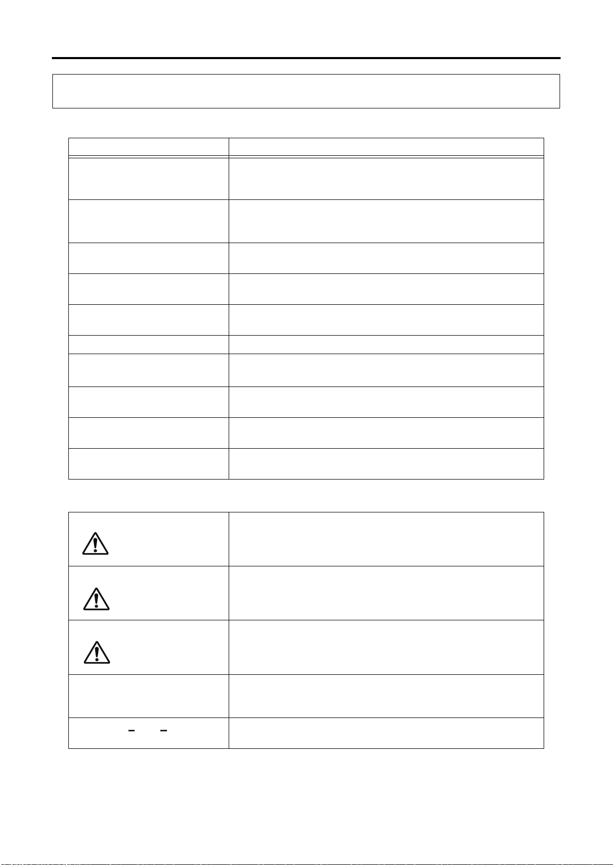
Notation Used in This Manual
Indicates an imminent hazard which, if not avoided, will result in
death or serious injury.
Indicates a potential hazard which, if not avoided, will result in
death or serious injury.
NOTICE
29F24D-2006EN
Indicates a possible hazard which, if not avoided, may result in
minor or moderate injury.
Indicates a potential situation which, if not avoided, may result in
physical damage to the machine or adversely affect the work
environment.
Indicates supplemental information for appropriate and efficient
work or better understanding of the operation.
Page 8

29F24D-2006EN
Page 9

Contents
Chap. 1 Safety
1 Safety Precautions .................................................................................. 1-1
1.1 Operator Checks .......................................................................................................... 1-2
1.2 Work Environment Checks ........................................................................................... 1-2
1.3 Precautions for Potential Fire Hazards ......................................................................... 1-3
1.4 Confirmation of Machine Status ................................................................................... 1-4
1.5 Pre-operation Checks ................................................................................................... 1-5
1.6 Implementing Lock-out and Tag-out ............................................................................. 1-7
1.7 During Work ................................................................................................................. 1-8
1.8 Handling of Hazardous and Toxic Materials ............................................................... 1-11
2 Warning Labels ..................................................................................... 1-12
2.1 Signal Word Definitions .............................................................................................. 1-12
2.2 Using Warning Labels ................................................................................................ 1-13
2.3 Information Contained in Warning Labels .................................................................. 1-14
2.3.1 Warning Labels with Warning Text ................................................................ 1-14
2.3.2 Warning Labels with Warning Marks Only .................................................... 1-14
2.4 Warning Label Locations ............................................................................................ 1-15
2.4.1 Area around Operator Door ........................................................................... 1-15
2.4.2 Area around Tool Magazine .......................................................................... 1-16
3 Safety Devices ...................................................................................... 1-17
3.1 "Emergency Stop" Switch ........................................................................................... 1-17
3.1.1 "Emergency Stop" Switch Installation Location (Machine Body) ................... 1-18
3.1.2 "Emergency Stop" Switch Installation Location
(Large Capacity Tool Magazine) ................................................................... 1-19
3.2 Door Switch ................................................................................................................ 1-20
3.2.1 Door Switch Installation Location (Machine Body) ........................................ 1-20
3.2.2 Door Switch Installation Location
(Disk Type Tool Magazine 21-tool/40-tool) ................................................... 1-21
3.2.3 Door Switch Installation Location (Large Capacity Tool Magazine) .............. 1-22
4 Work Hazards ....................................................................................... 1-23
4.1 Area Surrounding Machine ......................................................................................... 1-23
4.2 Electrical System ........................................................................................................ 1-24
4.3 Parameters ................................................................................................................. 1-24
4.4 Inside the Machining Chamber ................................................................................... 1-24
Page 10

Contents
4.5 Tool Magazine ............................................................................................................ 1-26
4.6 Cutting Fluid Supply Unit/Chip Disposal Device/
Cutting Fluid Temperature Controller/Dust Collector (Graphite Specifications) ......... 1-27
4.7 Temperature Controller .............................................................................................. 1-27
4.8 Hydraulic Unit ............................................................................................................. 1-28
4.9 Pneumatic Unit ........................................................................................................... 1-28
4.10 Splash Guard ............................................................................................................. 1-28
4.11 Other Peripheral Equipment ....................................................................................... 1-29
5 Occupational Health and Safety Management ..................................... 1-30
5.1 Safety Device Inspection ............................................................................................ 1-30
5.2 Noise .......................................................................................................................... 1-30
5.3 Personal Protective Equipment .................................................................................. 1-31
5.4 Disposal of Waste Products ....................................................................................... 1-32
5.4.1 Disposal of Waste Oil, Waste Fluids, and Waste Materials .......................... 1-32
5.4.2 Disposal of This Machine .............................................................................. 1-32
Chap. 2 Installation Preparation
1 Checking Installation Requirements ....................................................... 2-1
2 Allocation of Installation Area ................................................................. 2-2
3 Requirements for Carry-in Route ............................................................ 2-8
4 Installation Requirements ..................................................................... 2-15
5 Recommended Foundation Conditions ................................................ 2-16
6 Air and Power Sources ......................................................................... 2-19
7 Preparation of Equipment for Transfer/Installation ............................... 2-23
Chap. 3 Installation
1 Installation Work Flow ............................................................................. 3-1
2 Preparing Securing Fixtures for Shipment and Hoisting Attachment ...... 3-3
3 Hoisting the Machine Body ..................................................................... 3-5
3.1 Fixing Main Operation Panel ........................................................................................ 3-6
3.1.1 Fixing Main Operation Panel (When Transported on a Truck) ........................ 3-6
3.1.2 Fixing Main Operation Panel (When Transported in a Container) .................. 3-8
Page 11

Contents
3.2 Attaching Left Cover Securing Fixtures for Shipment ................................................ 3-10
3.3 Attaching Operator Door Securing Fixtures for Shipment .......................................... 3-12
3.4 Attaching Tool Magazine Door Securing Fixtures for Shipment ................................. 3-14
3.5 Hoisting ...................................................................................................................... 3-16
4 Hoisting the Peripheral Equipment ....................................................... 3-19
4.1 Hoisting the Cutting Fluid Supply Unit (Other than Graphite Specifications) ............. 3-20
4.2 Hoisting the Temperature Controller (Other than Graphite Specifications) ................ 3-21
4.3 Hoisting the Dust Collector (Graphite Specifications) ................................................ 3-22
5 Machine Setup ...................................................................................... 3-25
5.1 Setup of Machine Body .............................................................................................. 3-26
5.1.1 When Using Crane ........................................................................................ 3-26
5.1.2 When Using Forklift ....................................................................................... 3-28
5.2 Removing Hoisting Attachment .................................................................................. 3-30
5.3 Releasing Fixed Main Operation Panel ...................................................................... 3-32
5.3.1 Releasing Fixed Main Operation Panel (When Transported on a Truck) ...... 3-32
5.3.2 Releasing Fixed Main Operation Panel
(When Transported in a Container) ............................................................... 3-34
5.4 Removing Tool Magazine Door Securing Fixtures for Shipment ............................... 3-36
5.5 Removing Operator Door Securing Fixtures for Shipment ......................................... 3-37
5.6 Removing Left Cover Securing Fixture for Shipment ................................................. 3-38
5.7 Removing Machine Controller Securing Fixture for Shipment ................................... 3-39
5.8 Removing X-axis, Y-axis and Z-axis Securing Fixtures for Shipment ........................ 3-40
5.9 Releasing the Fixed Securing Bracket ....................................................................... 3-44
5.10 Adjusting the Height of the Tool Magazine ................................................................. 3-46
6 Setting Up the Peripheral Equipment and
Connecting the Piping and Wiring ........................................................ 3-47
6.1 Setting Up the Cutting Fluid Supply Unit and
Connecting the Piping and Wiring (Other than Graphite Specifications) .................... 3-48
6.2 Setting Up the Dust Collector and Connecting the Piping and Wiring (Graphite
Specifications) ............................................................................................................ 3-50
Page 12

Contents
7 Refilling Oil ............................................................................................ 3-51
7.1 Recommended Cooling Oil, Hydraulic Oil, and Lubricant .......................................... 3-51
7.2 Refilling Oil for the Temperature Controller ................................................................ 3-52
7.3 Refilling Oil for the Oil Air Supply Device ................................................................... 3-53
7.4 Refilling Oil for the Hydraulic Unit ............................................................................... 3-54
7.5 Refilling Oil for the Cutting Fluid Supply Unit
(Other than Graphite Specifications) .......................................................................... 3-56
8 Connecting the Power Supply and Air Source to the Machine ............. 3-59
8.1 Connecting the Power Supply to the Machine ........................................................... 3-59
8.2 Connecting the Air Source to the Machine ................................................................. 3-62
9 Work after Power Connection ............................................................... 3-63
9.1 Removing the Sleeper ................................................................................................ 3-63
9.2 Checking the Levelness of Installed Machine ............................................................ 3-64
9.3 Fixing the Leveling Block ............................................................................................ 3-65
9.4 Mounting Covers ........................................................................................................ 3-66
10 Operation Check ................................................................................... 3-67
Page 13

Chap. 1 Safety
1 Safety Precautions................................................................................... 1-1
1.1 Operator Checks ........................................................................................................... 1-2
1.2 Work Environment Checks............................................................................................ 1-2
1.3 Precautions for Potential Fire Hazards.......................................................................... 1-3
1.4 Confirmation of Machine Status ................................................................................... 1-4
1.5 Pre-operation Checks.................................................................................................... 1-5
1.6 Implementing Lock-out and Tag-out.............................................................................. 1-7
1.7 During Work .................................................................................................................. 1-8
1.8 Handling of Hazardous and Toxic Materials ............................................................... 1-11
2 Warning Labels...................................................................................... 1-12
2.1 Signal Word Definitions............................................................................................... 1-12
2.2 Using Warning Labels ................................................................................................. 1-13
2.3 Information Contained in Warning Labels ................................................................... 1-14
2.3.1 Warning Labels with Warning Text................................................................. 1-14
2.3.2 Warning Labels with Warning Marks Only ..................................................... 1-14
1
Safety
2.4 Warning Label Locations............................................................................................. 1-15
2.4.1 Area around Operator Door............................................................................ 1-15
2.4.2 Area around Tool Magazine .......................................................................... 1-16
3 Safety Devices ...................................................................................... 1-17
3.1 "Emergency Stop" Switch............................................................................................ 1-17
3.1.1 "Emergency Stop" Switch Installation Location (Machine Body).................... 1-18
3.1.2 "Emergency Stop" Switch Installation Location
(Large Capacity Tool Magazine) .................................................................... 1-19
3.2 Door Switch ................................................................................................................ 1-20
3.2.1 Door Switch Installation Location (Machine Body)......................................... 1-20
3.2.2 Door Switch Installation Location
(Disk Type Tool Magazine 21-tool/40-tool) .................................................... 1-21
3.2.3 Door Switch Installation Location (Large Capacity Tool Magazine) .............. 1-22
4 Work Hazards ....................................................................................... 1-23
4.1 Area Surrounding Machine.......................................................................................... 1-23
4.2 Electrical System......................................................................................................... 1-24
4.3 Parameters ................................................................................................................. 1-24
Page 14

4.4 Inside the Machining Chamber ................................................................................... 1-24
4.5 Tool Magazine............................................................................................................. 1-26
4.6 Cutting Fluid Supply Unit/Chip Disposal Device/
Cutting Fluid Temperature Controller/Dust Collector (Graphite Specifications) ......... 1-27
4.7 Temperature Controller ............................................................................................... 1-27
4.8 Hydraulic Unit .............................................................................................................. 1-28
4.9 Pneumatic Unit............................................................................................................ 1-28
4.10 Splash Guard .............................................................................................................. 1-28
4.11 Other Peripheral Equipment........................................................................................ 1-29
5 Occupational Health and Safety Management ...................................... 1-30
5.1 Safety Device Inspection ............................................................................................ 1-30
5.2 Noise ........................................................................................................................... 1-30
5.3 Personal Protective Equipment................................................................................... 1-31
5.4 Disposal of Waste Products ........................................................................................ 1-32
5.4.1 Disposal of Waste Oil, Waste Fluids, and Waste Materials ........................... 1-32
5.4.2 Disposal of This Machine ............................................................................... 1-32
Page 15

1 Safety Precautions
1 Safety Precautions
• Disregarding the specific instructions or precautions included in this manual may result in
serious injury or death to the operators or surrounding workers, or damage to the machine.
• Never disable or remove any safety device. Operating the machine while the safety devices are
disabled may result in serious injury, death, or damage to the machine.
• Observe the safety precautions provided in this manual at all times and fully implement safety
measures.
• Inspect and maintain the machine regularly to keep it in optimum operating condition. Do not run
the machine if it shows any signs of abnormal operation.
• The keys (release key for door switch, machine controller panel key, etc.) which are not
necessary for regular operation and maintenance must be removed from the machine and
managed by supervising personnel.
• The lubricating oil, cutting fluid, and other chemical substances used with the machine must be
managed by supervising personnel.
1
Safety
• Workpiece materials such as magnesium and titanium may cause a fire if mishandled, so be
particularly careful when machining workpieces and handling cutting chips made from these
types of materials.
29F24D-2006EN
1-1
Page 16
1 Safety Precautions
1.1 Operator Checks
1.1 Operator Checks
• Only qualified personnel who have adequate mechanical and technical knowledge are allowed
to operate and maintain the machine.
• Only qualified electrical engineers may perform electrical work.
• Only qualified personnel may use a crane or forklift.
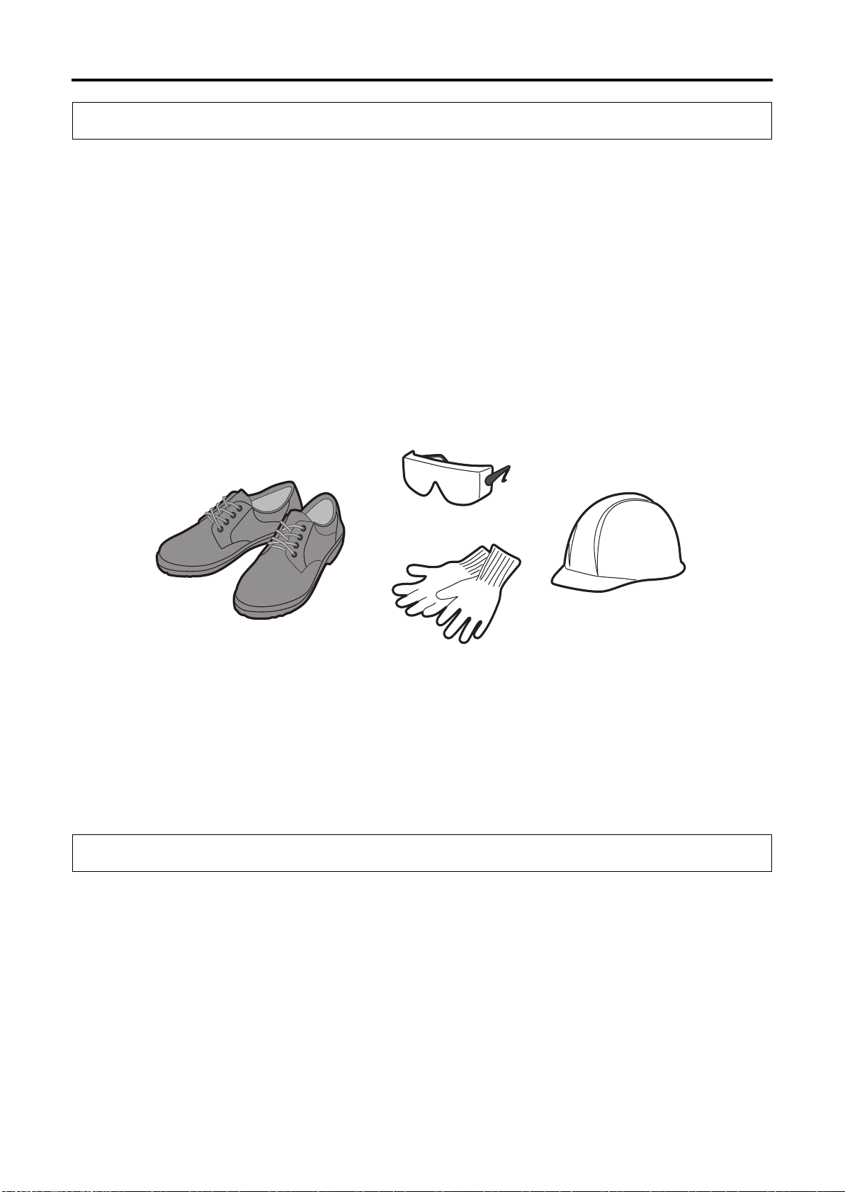
• Wear suitable work clothes whenever operating or maintaining the machine. Do not operate the
machine while wearing loose-fitting clothes, a necktie, jewelry, or any other clothing or objects
which may become entangled with the moving parts of the machine.
• Tie up long hair, and wear a cap.
• Wear safety glasses, safety shoes, safety cap (including safety helmet), and safety gloves as
needed.
• Protective gear should be worn to protect hearing when excessive noise may be generated
during operation or maintenance.
• Never operate any machinery while under the influence of alcohol or drugs.
• The operator should be in proper physical condition. If the operator suffers from a condition that
impairs judgment, it may result in serious injury or death.
1.2 Work Environment Checks
• Make sure the machine and surrounding area are fully lighted.
• Make sure the machine and surrounding area are tidy and clean at all times.
• Clean up any oil, cutting fluid, or chips scattered around the machine.
• When performing work at high locations, use a stable footstool or stepladder.
• Keep all flammable substances away from the work area.
• Maintain adequate working space.
1-2
29F24D-2006EN
Page 17

1 Safety Precautions
1.3 Precautions for Potential Fire Hazards
1.3 Precautions for Potential Fire Hazards
Use the machine by following the precautions below to protect the machine equipment, plant, and
surrounding environment from the danger of fire and to ensure the safety of operators.
1 When using cutting fluid, be sure to use a water-soluble cutting fluid (type A1).
There is no fire hazard when using water-soluble cutting fluids (except when using them with
special materials).
1
2 Oil-based cutting fluids present a potential fire hazard.
If an oil-based cutting fluid must be used due to unavoidable circumstances, be sure to
observe the precautions below.
• Do not run the machine in an unmanned operation mode.
• Install the proper fire-extinguishing equipment near the machine.
• Provide alarm devices to detect a fire, automatic fire-extinguishing devices, and other
equipment to the greatest extent possible.
• Do not create situations which may potentially start a fire.
• Machine under the proper cutting conditions.
• Perform proper tool management to prevent the occurrence of abnormal frictional heat
and sparks.
• Do not allow chips to accumulate in the machining chamber.
• Check that a constant and full supply of cutting fluid is provided.
• Always clean up and organize the area around the machine, and do not place
flammable objects in the area.
Safety
3 Precautions for machining of flammable solids, resins, wood, and other flammable materials.
When machining flammable solids or other special materials, be sure to fully implement safety
measures after gaining a thorough understanding of the material properties. Be sure to also
pay careful attention to safety when machining resins, wood, and other materials.
When machining materials that generate dust and powder, be sure to provide equipment that
takes into account the danger of a dust explosion for certain material types.
4 Precautions for machining while blowing air.
Because air blowing has weak cooling performance, the chips that spray and fly out in the
surrounding area are extremely hot. Do not place flammable objects in the machining
chamber or in the area surrounding the machine.
29F24D-2006EN
1-3
Page 18

1 Safety Precautions
1.4 Confirmation of Machine Status
1.4 Confirmation of Machine Status
• Machine inspections and maintenance must be performed regularly to maintain optimum
machining accuracy and long-term performance, and increase machine operating efficiency.
• Confirm that all safety devices are functioning normally.
• Make sure the operator knows the location of the "Emergency Stop" switches to enable easy
access in the event of an abnormal or dangerous situation (Refer to 3.1 "Emergency Stop"
Switch).
• Check for any loose, damaged, or worn parts on the machine. Operating the machine in a
condition in which any of the parts has an abnormality may cause abnormal noises or damage to
the machine.
• Check for any damaged piping or wiring. Operating the machine with the piping or wiring left
damaged may cause oil leakage, electrical shock, or fire.
• Use the most appropriate cutting tool, tool holder, retention knob, and workpiece, and make sure
that they are all secured firmly in place. Otherwise, the workpiece may fall or the tool may fly out,
and this may result in damage to the machine, serious injury, or death.
• Check that the tool numbers are registered correctly. Otherwise, the spindle may rotate at a
speed outside the allowable range, the tool may fly out, and this may result in damage to the
machine, serious injury, or death.
1-4
29F24D-2006EN
Page 19

1 Safety Precautions
1.5 Pre-operation Checks
1.5 Pre-operation Checks
• Be sure that you fully understand the work procedures and precautions before operating and
maintaining the machine. Never operate any machinery if you are unsure about any points.
• Check that the clothes you are wearing are suitable for operation.
• Perform periodic maintenance.
• Confirm that all safety devices are functioning properly before operating and maintaining the
machine.
• Periodically back up the parameters when the machine was shipped and the program and offset
data that have been prepared by the customer. Makino is not liable for any program or offset
data that is corrupted or lost.
• Makino does not accept responsibility for any trouble caused by apparatus or programs
prepared by the customers, such as damage to workpieces or the machine.
• For details about replacement parts, contact your Makino service representative. Use of
improper parts may result in reduced machine performance or safety, damage to the machine, or
operator injuries.
1
Safety
• Before entering inside the machine to perform work, be sure to confirm the escape procedure in
the event that you inadvertently become shut inside the machine.
• Perform the lock-out and tag-out procedures.
• Make sure the operator knows the location of the "Emergency Stop" switches for each device so
that they can be easily operated in the event of an abnormal or dangerous situation.
• Be sure to observe the information on the warning labels. Contact your Makino service
representative if a warning label comes off or becomes illegible.
• When handling a hazardous or toxic material (oils, cutting fluids, and other chemical
substances), obtain the safety data sheet (SDS), and follow the instructions. The safety data
sheet (SDS) contains information about the safe handling of hazardous and toxic materials, and
emergency measures.
29F24D-2006EN
1-5
Page 20

1 Safety Precautions
1.5 Pre-operation Checks
• For the graphite specifications, do not let the dust collector collect anything other than graphite
dust. Failure to observe this precaution may result in a dust explosion. Also, it may damage the
filter or cause other malfunctions.
• For the graphite specifications, observe the following precautions to prevent health problems
related to the inhalation of graphite dust.
• After machining the workpieces, wait for the dust collector to remove airborne dust particles
before opening the operator door. If you open the operator door immediately after
machining, the airborne dust will disperse throughout the machining room.
• Wear a high-performance dust-proof mask when doing the following (particle collection
efficiency of 99.9% or more is recommended).
• Opening and closing the operator door
• Performing an operation with the operator door open
• Replacing a tool in the tool magazine
• Handling dust
• Do not remove the dust car and chip bucket while the dust collector is operating. Otherwise,
dust will disperse in the surrounding area.
1-6
29F24D-2006EN
Page 21
1 Safety Precautions
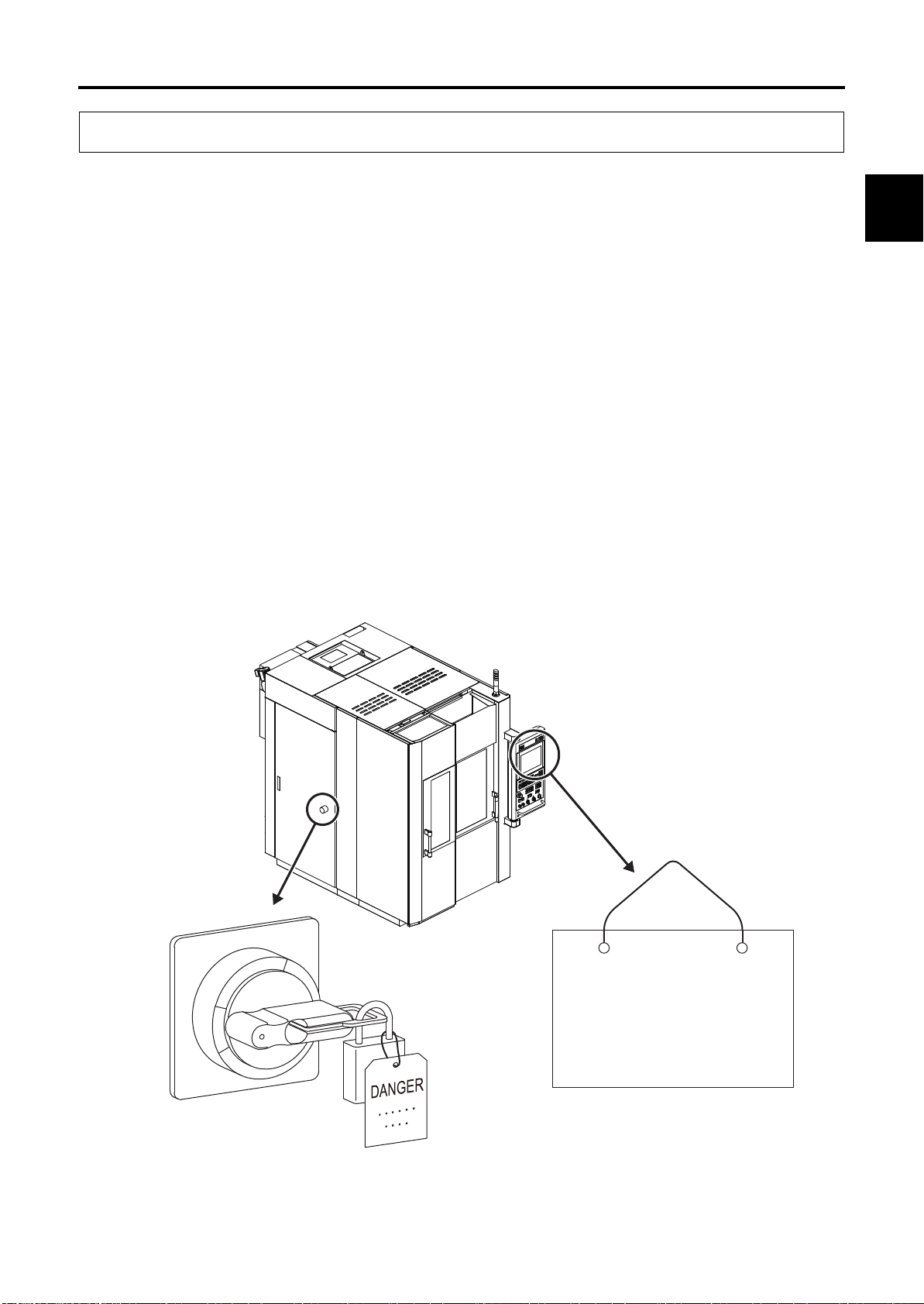
1.6 Implementing Lock-out and Tag-out
1.6 Implementing Lock-out and Tag-out
Lock-out consists of shutting down the power source to the machine or devices and locking it.
Example: Set the main power switch to the "OFF" position and secure it using a padlock or a
lockout device such as a cover.
Tag-out consists of placing a warning tag to prevent anyone from turning ON the power.
Example: Place a "Do Not Operate" or "Under Maintenance" sign with the operator's name and
department and indicating that machine operation is prohibited on the main power switch and
main operation panel.
Lock-out/tag-out should be performed to prevent inadvertent operation and ensure operator safety.
• Performing lock-out/tag-out alone does not completely ensure operator safety. The operator
must read and thoroughly understand the work procedures and safety precautions, and always
be aware of potential hazards.
Each operator should perform lock-out or tag-out by himself or herself. Perform this procedure before
starting the work, and release the lock and remove warning tag yourself after finishing work. Never
release a lock and remove a sign without confirming with the operator or without the presence of the
operator himself or herself.
Be sure to clearly define and implement the lock-out and tag-out procedures of your company.
1
Safety
29F24D-2006EN
OFF
OFF
ON
ON
Figure 1-1 Implementing Lock-out and Tag-out
DANGER
DANGER
Under Maintenance/
Under Maintenance/
Inspection
Inspection
Operator's Name: xxxxx
Operator's Name: xxxxx
Department: xxxxx
Department: xxxxx
1-7
Page 22

1 Safety Precautions
1.7 During Work
1.7 During Work
• Turn OFF the power before performing maintenance of the machine. When work must be
performed with the machine power ON, confirm that all machine operations are completely
stopped. Check that any residual energy in the machine is completely discharged.
• Never go near the moving parts of the machine. If you must approach moving parts to perform
maintenance, be sure to take adequate safety precautions. Inadequate attention to safety may
result in death or another serious accident.
• Always keep the doors and covers closed during operation. If you must work with the doors and
covers open, be sure to take adequate safety precautions. Inadequate attention to safety may
result in death or another serious accident.
• If an operator gets trapped inside the machine, press the "Emergency Stop" switch regardless of
whether the machine power is ON or OFF.
• If the machine is stopped by a power failure or power supply fault, turn OFF the machine power.
If the power is not turned OFF, the machine may start operating unexpectedly when the power is
restored, and this may result in serious injury, death, or damage to the machine.
• If the machine is stopped by a power failure or power supply fault, check that the parameter,
program, and offset data have not been corrupted. The machine may be damaged if it is
operated using corrupted data.
• Be aware of the movement range of the machine and auxiliary components (each axis stroke,
rotation range, etc.), and keep all body parts clear of moving components.
• When two or more people are required for maintenance work, be sure to maintain clear
communication at all times to ensure operator safety. When performing work, be ready to press
the "Emergency Stop" switch at any time.
• Be sure to always pay attention to the safety precautions listed on the warning labels affixed to
the machine (Refer to 2 Warning Labels2 Warning Labels).
• Do not operate the switches or change the circuits except for adjustment purposes. In particular,
operating the machine with the interlock(s) or other safety devices or functions disabled is
extremely dangerous and may result in death or damage to the machine.
• If a circuit or other component needs to be changed for adjustment purposes, be sure to return it
to the original setting after adjustment is completed.
• The optimum values for the NC parameters and machine parameters are set when the machine
is shipped. Do not change any parameter setting unless it is described in the manual. Also, be
sure that you fully understand the function of a parameter before attempting to change the
parameter setting, and return the parameter to its original setting after the work is completed. If
you try to operate the machine without the proper settings, the machine may operate
unexpectedly, and this may result in serious injury, death, or damage to the machine.
• If the memory clear operation needs to be performed, be sure to contact your Makino service
representative beforehand.
• If an alarm is triggered, eliminate the cause of the alarm using the appropriate procedure. If the
remedy procedure is unclear, contact your Makino service representative.
• Never climb onto the covers. This may deform the covers or result in injury.
1-8
29F24D-2006EN
Page 23

1 Safety Precautions
1.7 During Work
• When using a stepladder or stool, it should be sturdy, safe, and have anti-slip surfaces.
• If any oils or cutting fluids get into your eyes, body, or on your skin surface, they may cause
severe health problems. Wear safety gloves, mask, safety glasses, and other safety equipment.
• Wear safety gloves whenever handling chips, tools, and workpieces.
• Protective gear should be worn to protect hearing when excessive noise may be generated
during operation or maintenance.
• If lubricating oil, grease, cutting fluid, or other substances are spilled on the floor, it may result in
slippage, causing injury. Wipe up any spilled fluids as soon as possible.
• Never touch a switch, button, or key while your hands are wet. Failure to observe this precaution
may result in electric shock.
• Some devices (motors, lighting equipment, valves, etc.) may become very hot while the machine
is operating and remain hot soon after the power is turned OFF, so be careful to avoid burns.
• Do not subject the machine to sudden impact or jolts. This may cause the machine to perform an
unexpected motion or result in damage to the machine.
• Do not use the machine for operation outside the specifications or exceeding the performance
range. This may cause the machine to perform an unexpected motion or result in serious injury,
death, or damage to the machine.
• Use the most appropriate cutting tool, tool holder, retention knob, and workpiece, and make sure
that they are all secured firmly in place. Otherwise, the workpiece may fall or the tool may fly out,
and this may result in damage to the machine, serious injury, or death.
1
Safety
• Be careful that you do not leave objects such as tools or jigs inside the machine.
• Do not place the tools, workpiece, or other parts on an unstable location.
• When a lifting sling or attachment is necessary, verify that it is strong enough to support the
weight of the parts. Confirm that no one is close to the machine and the parts are well balanced,
and be careful not to hit to the machine.
• Never go under a load that is being lifted. While transferring the hoisted load, constantly pay
careful attention to the hoisted load during the operation.
• Check that the tool numbers are registered correctly. Otherwise, the spindle may rotate at a
speed outside the allowable range, the tool may fly out, and this may result in damage to the
machine, serious injury, or death.
• Never insert hands or feet into the chip conveyor. They may be pulled in, and this may result in
death or another serious accident.
29F24D-2006EN
1-9
Page 24

1 Safety Precautions
1.7 During Work
• For the graphite specifications, observe the following precautions to prevent health problems
related to the inhalation of graphite dust.
• After machining the workpieces, wait for the dust collector to remove airborne dust particles
before opening the operator door. If you open the operator door immediately after
machining, the airborne dust will disperse throughout the machining room.
• Wear a high-performance dust-proof mask when doing the following (particle collection
efficiency of 99.9% or more is recommended).
• Opening and closing the operator door
• Performing an operation with the operator door open
• Replacing a tool in the tool magazine
• Handling dust
• Do not remove the dust car and chip bucket while the dust collector is operating. Otherwise,
dust will disperse in the surrounding area.
1-10
29F24D-2006EN
Page 25

1 Safety Precautions
1.8 Handling of Hazardous and Toxic Materials
1.8 Handling of Hazardous and Toxic Materials
Handlers of hazardous and toxic materials (such as oils and cutting fluid) must receive information,
education, and training in accordance with the stipulations in JIS Z 7253 (revised March 2012)/
ISO 11014: 2009.
Particular attention must be paid to the following points.
• Be sure that there is adequate ventilation in areas where hazardous and toxic materials are
used.
• Hazardous and toxic materials must be handled and stored based on the handling procedures
recommended by the manufacturer.
• Identify hazardous and toxic materials by affixing labels to their containers.
• Assign a person in charge to handle the hazardous and toxic materials, and provide education
and training in emergency response procedures and handling procedures.
• Before handling any hazardous or toxic material, be sure to check the safety data sheet (SDS).
The safety data sheet (SDS) contains detailed information on health and safety hazards, safe
handling procedures, and responses to emergency situations.
1
Safety
29F24D-2006EN
1-11
Page 26
2 Warning Labels
DANGER
WARNING
CAUTION
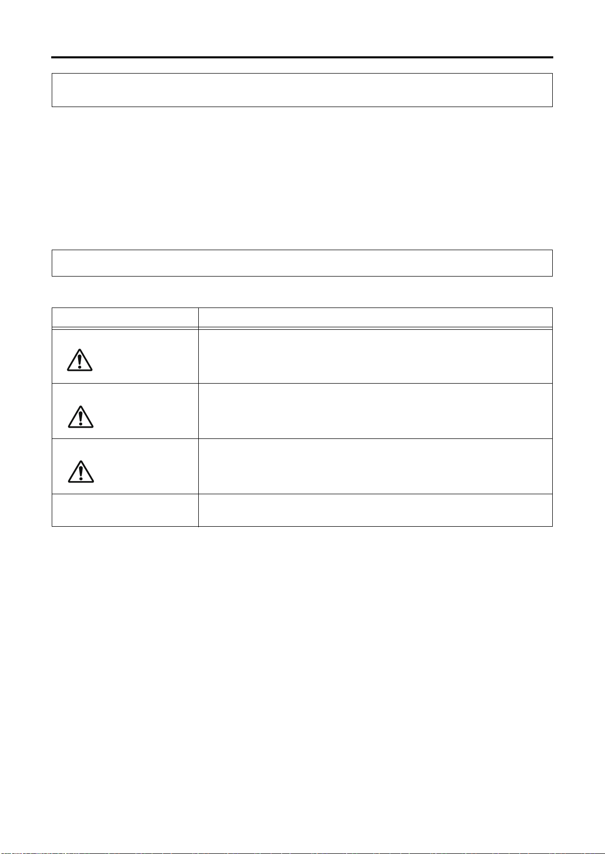
2.1 Signal Word Definitions
2 Warning Labels
Warning labels are affixed to machine parts that are potentially hazardous to warn operators about the
hazard and its level of danger and ensure the safety of operators.
The warning labels include symbols to indicate the source of the danger, signal words to indicate the
level of danger, and warning text to describe how to prevent the danger. When working at a location
where a warning label is affixed, make sure that you fully understand the warning label information and
definitions and follow the warning text that is provided. Failure to observe the information in the
warning labels may result in death or another serious accident or damage to the machine.
2.1 Signal Word Definitions
Signal words are divided into four classes based on the degree of expected risk.
Signal Word Description
NOTICE
Indicates an imminent hazard which, if not avoided, will result in death or
serious injury.
Indicates a potential hazard which, if not avoided, will result in death or
serious injury.
Indicates a possible hazard which, if not avoided, may result in minor or
moderate injury.
Indicates a potential situation which, if not avoided, may result in physical
damage to the machine or adversely affect the work environment.
1-12
29F24D-2006EN
Page 27

2.2 Using Warning Labels
• Do not cover up or peel off the warning labels.
2 Warning Labels
2.2 Using Warning Labels
• Confirm that the operators and maintenance personnel are familiar with the language on the
labels. If labels in other languages are required, contact your Makino service representative.
• Check that all the information in the warning label is legible. If any portion of the warning text or
symbol is not visible, clean by wiping with a soft cloth dipped in water or household cleanser. Do
not use organic solvents or gasoline. These may damage the surface of the warning label.
• Replace the warning label if the information in the warning label is no longer visible. To obtain
new warning labels, contact your Makino service representative.
• If a part is replaced where a warning label was affixed, obtain a new warning label and affix it at
the same position as before on the new part. To obtain new warning labels, contact your Makino
service representative.
1
Safety
29F24D-2006EN
1-13
Page 28
2 Warning Labels
DANGER
DANGER
DANGER
CAUTION
CAUTION
2.3 Information Contained in Warning Labels
2.3 Information Contained in Warning Labels
The two types of warning labels are shown below.
• Labels with warning text and a warning mark
• Labels with a warning mark only
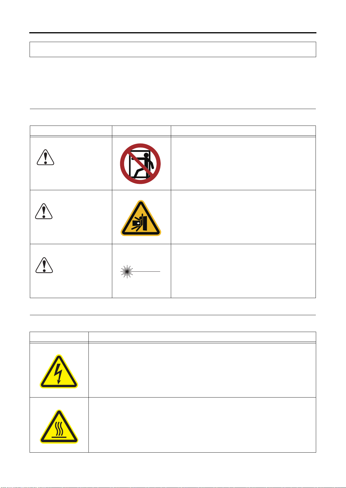
2.3.1 Warning Labels with Warning Text
Signal Word Symbol Description
This warning label is affixed to areas where entry is
prohibited.
This warning label is affixed to areas where there is a
risk of getting pressed, being sucked in, stabbed, or
falling down, resulting in a serious injury, accident, or
death.
Maximum output 1mW, semiconductor laser
Class 2 laser product
Do not stare into the beam.
2.3.2 Warning Labels with Warning Marks Only
Symbol Description
This warning label is affixed to parts where touching the internal high-voltage
components may result in electrical shock.
Workers who are not qualified electrical engineers must not access the parts where
this warning label is affixed.
1-14
This warning label is affixed to parts that may become extremely hot.
Do not touch parts where this warning label is affixed. Be particularly careful
immediately after operation because these parts are extremely hot at this time.
29F24D-2006EN
Page 29
2 Warning Labels
2.4 Warning Label Locations
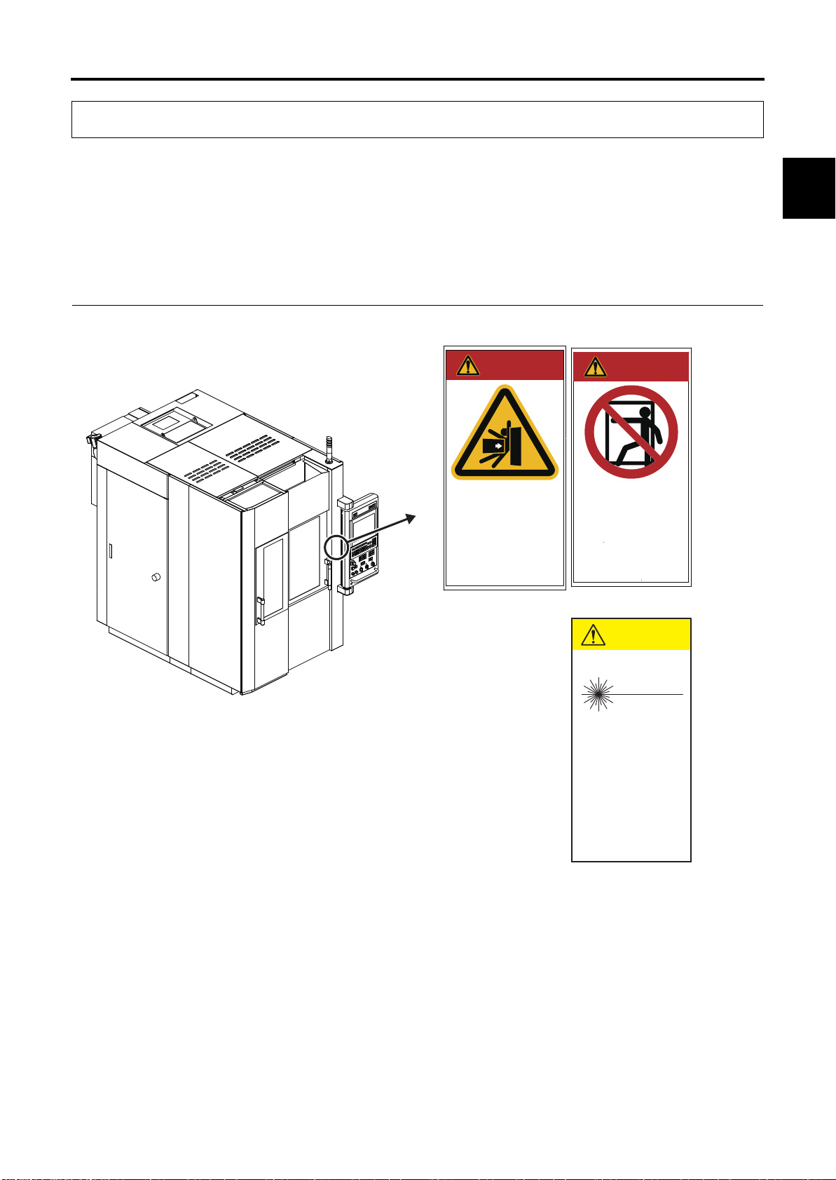
2.4 Warning Label Locations
The type of warning label and the location where the label is affixed to vary depending upon the
machine model.
Warning labels with warning marks only are affixed to various locations on the machine, and all affixing
locations are not shown in the figure.
1
2.4.1 Area around Operator Door
DANGER
危 険
Serious Injury / Death
死傷に至る
Crush, Pinch, Stab,
Slip and Fall Hazard
押しつぶし、巻込み、
突刺し、転倒、転落
Safety
DANGER
危 険
DO NOT ENTER
機械内部立入禁止
Authorized Personnel Only
許可された者以外
CAUTION
注意
29F24D-2006EN
DONOT Stare into Beam
レーザー光を覗き込むな
Power 1mW
Semiconductor laser
Class2 laser product
最大出力1mW
半導体レーザ
クラス2 レーザ製品
(When an automatic non-contact
type tool measurement device is
included)
Figure 2-1 Area around Operator Door
1-15
Page 30
2 Warning Labels
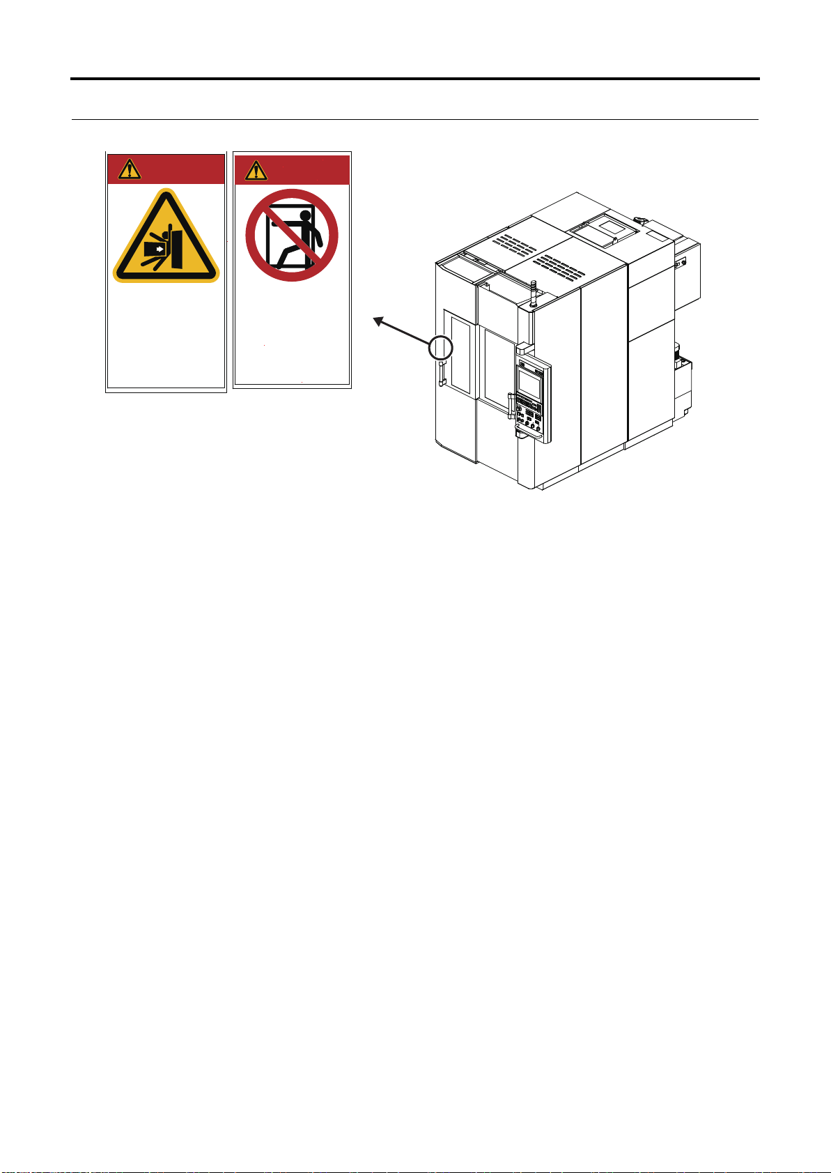
DANGER
危 険
許可された者以外
機械内部立入禁止
DO NOT ENTER
Authorized Personnel Only
Serious Injury / Death
死傷に至る
押しつぶし、巻込み、
突刺し、転倒、転落
Crush, Pinch, Stab,
Slip and Fall Hazard
DANGER
危 険
2.4 Warning Label Locations
2.4.2 Area around Tool Magazine
Figure 2-2 Area around Tool Magazine
1-16
29F24D-2006EN
Page 31

3 Safety Devices
DANGER
WARNING
3.1 "Emergency Stop" Switch
3 Safety Devices
• Never disable or remove any safety device.
Safety devices are installed on the machine to protect operators and maintenance personnel. The
safety devices also include ones that function on the condition that the operator observes the safety
procedures.
3.1 "Emergency Stop" Switch
• Make sure operators know the locations of all the "Emergency Stop"
switches prior to performing machine operation or maintenance to enable
use in an abnormal or dangerous situation.
1
Safety
The machine goes to the following status when the "Emergency Stop" switch is pressed:
• Feeding of the axes is stopped immediately.
• Spindle rotation stops if it is rotating.
• The spindle is clamped if it has been unclamped.
• When orientation of the spindle has been performed, orientation is reset.
• When a tool is being changed or the tool magazine is operating, operation stops immediately
(even during motion).
• The chip conveyor in operation comes to an immediate stop.
• The hydraulic unit is stopped.
• The cutting fluid supply is stopped.
• Supply of the air blow inside the machining chamber is stopped (graphite specifications).
• The dust collector stops collecting dust (graphite specifications).
• Energizing of all solenoid valves is reset.
• The NC is reset.
Once the "Emergency Stop" switch is pressed, it is locked in the pressed position. The lock can be
released by turning the switch in the direction indicated by the arrow or pulling out the switch.
Then, pressing the [CONTROL POWER ON] switch cancels the emergency stop state.
For details about recovery procedures following machine operation stopped by the "Emergency Stop"
switch activation (Refer to Instruction Manual Chap. 7 Troubleshooting 2.1 Recovery from Emergency
Stop Status).
29F24D-2006EN
1-17
Page 32

3 Safety Devices
3.1 "Emergency Stop" Switch
3.1.1 "Emergency Stop" Switch Installation Location (Machine Body)
崒嵒崐嵛
ૃ କ
౺જ ౪౺ো
崱崊嵕崫崗
崊嵛崗嵑嵛崿
崝崌崗嵓
崽崋嵤崱
崡崧嵤崰
嵃嵤嵓崱
1
崮嵤崟嵏嵛
(FR
ౣૐ
嵉嵊嵒
৸ກ୮ష
્ઐఌ ജ岶峁
ু
0',
සྩ
崾嵕崫崗崡崕崫崿
઼୮ష
崶崢嵓
崒崿崟嵏崲嵓
崐崊崾嵕嵤
崗嵤嵑嵛崰
崡崰崫崿
崗嵤嵑嵛崰೬ૃ
崟嵛崘嵓崾嵕崫崗
1
Figure 3-1 "Emergency Stop" Switch Installation Location (Machine Body)
No. Name
1 "Emergency Stop" switch
Z
X10 X100
4
5
Y
X1
X1000
6
X
AUX
OFF
ABS
MAC
REL
ORG
1
1-18
29F24D-2006EN
Page 33

3 Safety Devices
3.1 "Emergency Stop" Switch
3.1.2 "Emergency Stop" Switch Installation Location (Large Capacity Tool Magazine)
1
Safety
1
1
Figure 3-2 "Emergency Stop" Switch Installation Location (Large Capacity Tool Magazine)
No. Name
1 "Emergency Stop" switch
29F24D-2006EN
1-19
Page 34

3 Safety Devices
3.2 Door Switch
3.2 Door Switch
The door switch is a device for detecting and controlling the status of doors.
3.2.1 Door Switch Installation Location (Machine Body)
1
Figure 3-3 Door Switch Installation Location (Machine Body)
No. Name
1 Door switch
1-20
29F24D-2006EN
Page 35

3 Safety Devices
3.2 Door Switch
3.2.2 Door Switch Installation Location (Disk Type Tool Magazine 21-tool/40-
tool)
1
1
Safety
Figure 3-4 Door Switch Installation Location (Disk Type Tool Magazine 21-tool/40-tool)
No. Name
1 Door switch
29F24D-2006EN
1-21
Page 36

3 Safety Devices
1
1
3.2 Door Switch
3.2.3 Door Switch Installation Location (Large Capacity Tool Magazine)
Figure 3-5 Door Switch Installation Location (Large Capacity Tool Magazine)
No. Name
1-22
1 Door switch
29F24D-2006EN
Page 37

4 Work Hazards
4.1 Area Surrounding Machine
4 Work Hazards
The following tables list examples of hazardous actions and situations during machine operation and
maintenance and examples of the resulting accidents and incidents that may occur.
The points that the operator must observe when performing machine operation and maintenance vary
depending on the situation. All possible points cannot be covered in the content of this manual.
Therefore, be sure to fully understand the machine, and remain constantly aware of safety and the
potential hazards while doing work.
Improper operation may result in death or damage to the machine.
4.1 Area Surrounding Machine
Action/Situation Result
1
Safety
Tripping on piping/wiring Falling
Operator working on oily floor Fall, bone fracture, injury
Bringing an open flame into the area Fire, burn
Improper handling of chemical substances Skin lesions, eye injury, or respiratory
problems
29F24D-2006EN
1-23
Page 38

4 Work Hazards
NOTESNOTES
4.2 Electrical System
4.2 Electrical System
Action/Situation Result
Performing inspection or maintenance operation without turning
OFF the power (Refer to NOTE)
Touching a device with residual voltage (Refer to NOTE) Electrical shock
Miswiring Breakdown of the machine, abnormal
Loose screw in terminal block or other location Breakdown of the machine, abnormal
Machine controller door or junction box cover is left open Electric leakage, breakdown of the
Touching switches with wet hands Electrical shock
Damage to wiring on floor Electric leakage, breakdown of the
Operation or maintenance by non-qualified personnel Breakdown of the machine
1 Prior to performing maintenance of the servo amplifiers, spindle amplifiers, and inverters, turn OFF the main power and
confirm that the LED which indicates charging (red) for each amplifier and inverter is off.
2 High voltage current flows through components inside the junction box.
3 High voltage current continues to flow on the primary side of the main power switch even after the main power is turned
OFF.
4 Electrical current continues to flow to lamps and outlets in the machine controller even after the main power is turned
OFF.
Electric shock, breakdown of the machine,
abnormal operation, fire
operation, fire
operation, fire
machine, abnormal operation, fire
machine, abnormal operation, fire
4.3 Parameters
Action/Situation Result
Changing NC/machine parameters not listed in manual Injury or death, workpiece damage,
breakdown of the machine
Forgetting to return the parameter to its original value after
adjustment
Injury or death, workpiece damage,
breakdown of the machine
4.4 Inside the Machining Chamber
Action/Situation Result
Working without performing lock-out and tag-out Injury or death, damage to the
machine
Operator entering machining chamber without turning OFF the
power
Injury or death
1-24
29F24D-2006EN
Page 39

4 Work Hazards
4.4 Inside the Machining Chamber
Action/Situation Result
Operator entering machining chamber with safety devices or
functions disabled
Getting near the operating range of an axis when the power is turned
ON or during axis feeding
Replacing the gravity axis motor without using the fixing jig Injury or death, damage to the
Rotating spindle prior to cleaning of tapered section while operator
door is open
Rotating unbalanced tool at high speed while operator door is open Injury or death, damage to the
Hand or other body part becomes wedged in operator door when it is
opened or closed
Operator touching rotating spindle Hands or fingers cut off, body part
Touching a feed axis motor Burns
Workpiece has not been clamped Injury, bone fracture, bruises
Entering machining chamber when table is inclined Injury, bruises
Touching an operating ATC shutter Injury
Injury or death
Injury, bone fracture, bruises
machine
Injury or death, damage to the
machine
machine
Injury, bone fracture, bruises
becomes entangled, or other serious
injury or death
1
Safety
Operator becomes entangled in chip conveyor Body part pulled in, resulting in injury
or death
Climbing on top of covers Fall, bone fracture, injury
Climbing on top of the movable covers, inserting your hand into the
gaps
Operator working on oily floor Fall, bone fracture, injury
Touching the wipers Cuts to hands
Operator touching bladed tools Cuts, injuries to hands
Holding a heavy tool Strained back, hands become
Operator being struck by chips, cutting fluid, or dust scattered during
machining
Operator being splashed by cutting fluid dripping from ceiling in
machining chamber
Operating machine while there is abnormal vibration or abnormal
noise
Operating machine with a tool incorrectly clamped Injury or death, damage to the
Opening the operator door and entering the machining chamber
while mist is not being collected
Injury, bruises
wedged between tool and object
Damage to eyes, cuts or burns to skin
Damage to eyes, skin irritation
Damage to the machine
machine
Respiratory problems
Cleaning without wearing protective gloves Cuts to hands
Opening the operator door or entering the machining chamber while
dust is not being collected
Entering the machining chamber without wearing a dust-proof mask Respiratory problems
29F24D-2006EN
Respiratory problems
1-25
Page 40

4 Work Hazards
4.5 Tool Magazine
Action/Situation Result
Fastening tools or implementing other work during spindle
orientation
Inhaling dust Respiratory problems
Injury, bone fracture, bruises
4.5 Tool Magazine
Action/Situation Result
Working without performing lock-out and tag-out Injury or death, damage to the
machine
Operator entering the tool magazine without turning OFF the power Injury or death
Operator entering the tool magazine with the safety devices and
functions disabled
Manually changing tools by entering inside the tool magazine Injury or death
Performing T command or tool change while tool blade or tool is
mounted incorrectly
Tool number is registered incorrectly Damage to the machine
Operator inserting hands into tool magazine during tool magazine
operation
Injury or death
Injury or death, damage to the
machine
Cuts, bone fracture of hands
Touching the tool magazine motor Burns
Operator working on oily floor Fall, bone fracture, injury
Operator touching bladed tools Cuts, injuries to hands
Holding a heavy tool Strained back, hands become wedged
between tool and object
Hand or other body part becomes wedged in tool magazine door
when it is opened or closed.
Leaving a safety guard or maintenance cover opened or removed Injury
Holding or carrying a removed cover Injury or machine damage due to
Performing cleaning or maintenance while a tool is stored in the tool
magazine
Cleaning without wearing protective gloves Cutting or stabbing of hand
Injury, bruises
dropping of cover
Cutting or stabbing of hand or body
1-26
29F24D-2006EN
Page 41

4 Work Hazards
4.6 Cutting Fluid Supply Unit/Chip Disposal Device/Cutting Fluid Temperature Controller/Dust Collector
4.6 Cutting Fluid Supply Unit/Chip Disposal Device/Cutting Fluid
Temperature Controller/Dust Collector (Graphite Specifications)
Action/Situation Result
Working without performing lock-out and tag-out Injury or death, damage to the
machine
1
Inserting hands or feet into conveyor or tank without turning OFF the
power
Touching part or component immediately after operation Burns
Operator touching moving parts when chip discharge outlet cover is
removed
Stepping on a tank that is not fixed Fall, bone fracture, injury
Operating with low levels of cutting fluid Fire, damage to the machine
Touching cutting fluid or chemical additives Skin irritation
Touching chips Cuts, injuries, burns to hands
Replacing the filter without prior cleaning Cuts, injuries to hands
Inhaling large quantities of cutting fluid mist Respiratory organ damage
Mixing different brands of oils Breakdown of the machine
Failing to properly clean or collect flammable cutting chips or sludge Fire
Mixing cutting chips made from different materials Fire
Performing operation without wearing protective gloves Cuts, injuries to hands
Inhaling dust Respiratory problems
Serious injury due to body part
becoming entangled, or cuts to hands
and feet
Serious injury due to body part
becoming entangled
Safety
4.7 Temperature Controller
Action/Situation Result
Touching part or component immediately after operation Burns
Oil temperature exceeds flash point.
Flash point of Makino Spindle Lubricant: 95C
Changing filters without reducing the internal pressure Injury or death, damage to the
Performing operations without safety gloves, mask, and other
protective gear
Mixing different brands of oils Breakdown of the machine
Fire
machine
Damage to eyes, skin irritation,
accidental ingestion, or respiratory
organ damage
29F24D-2006EN
1-27
Page 42

4 Work Hazards
4.8 Hydraulic Unit
4.8 Hydraulic Unit
Action/Situation Result
Working without performing lock-out and tag-out Injury or death, damage to the
machine
Operator working on oily floor Fall, bone fracture, injury
Hand or other body part becomes wedged in tool magazine door
when it is opened or closed.
Leaving a safety guard or maintenance cover opened or removed Injury
Touching part or component immediately after operation Burns
Oil temperature exceeds flash point.
Flash point of standard hydraulic oil: Approximately 200C
Changing filters without reducing the internal pressure Injury or death, damage to the
Performing operations without safety gloves, mask, and other
protective gear
Mixing different brands of oils Breakdown of the machine
Injury, bruises
Fire
machine
Damage to eyes, skin irritation,
accidental ingestion, or respiratory
organ damage
4.9 Pneumatic Unit
Action/Situation Result
Removing the pneumatic unit source piping on the machine side or
disassembling the primary-side line filter without shutting of the air
supply from the factory facilities
Injury due to flying off of parts or
impact
Removing the pneumatic unit source piping on the machine side or
disassembling the primary-side line filter without releasing the
residual pressure in the air piping (inside the air circuit)
Injury due to flying off of parts or
impact
4.10 Splash Guard
Action/Situation Result
Working without performing lock-out and tag-out Injury or death, damage to the machine
Operator entering splash guard with the safety devices and
functions disabled
Operating the machine with the covers removed Injury or death
Holding or carrying a removed cover Injury or machine damage due to
Operator working on oily floor Fall, bone fracture, injury
Operator working at elevated locations Fall, bone fracture
1-28
Injury or death
dropping of cover
29F24D-2006EN
Page 43

4.11 Other Peripheral Equipment
4 Work Hazards
4.11 Other Peripheral Equipment
Action/Situation Result
Performing operation without turning OFF the power Injury or death, electric shock
1
Safety
29F24D-2006EN
1-29
Page 44

5 Occupational Health and Safety Management
NOTE
CAUTION
5.1 Safety Device Inspection
5 Occupational Health and Safety Management
5.1 Safety Device Inspection
Perform periodic maintenance and inspection of the safety devices used on this machine in order to
ensure that they continue to function normally. Make sure that all maintenance staff fully understand
the types of safety devices, functions, and locations described in 3 Safety Devices before performing
any maintenance work.
Before starting operation or maintenance work, inspect the safety devices, and if any are not
functioning properly, abort machine operation.
5.2 Noise
The noise level of the machine is shown below.
• Noise level: 80 dB maximum (A-weighted sound level)
These values are measured values at full operation (maximum rotation of the spindle without
machining a workpiece) with the safety guards and covers correctly mounted and all doors closed.
• When a workpiece is machined, noise at 80 dB or higher may occur under
certain customer cutting conditions. When performing work near the
machine during machining, be sure to wear ear protection and other
equipment to ensure that your health is not harmed.
Performing work without wearing ear protection may lead to hearing loss.
NOTE
The above noise level is measured at a location that is a distance of 0.5 m from the machine and a height of 1.2 m above
the floor.
1-30
29F24D-2006EN
Page 45

5 Occupational Health and Safety Management
WARNING
5.3 Personal Protective Equipment
5.3 Personal Protective Equipment
When conducting installation, operation, and maintenance work on the machine, be sure to protect
your body from the following potential hazards.
• Mechanical hazards
• Hazardous and toxic materials
•Heat
1
•Noise
Be sure to always use protective equipment to protect your body from these hazards. Some examples
of protective equipment are shown below.
Protected
Body Part
Head Bruises and cuts,
Eyes, nose,
mouth, face
Eyes Laser beam Laser safety goggles • Work performed with the eyes
Ears Noise Earplugs • Work where the environment
Hands Cuts, burns, and
Feet Bruises Safety shoes • Handling and transporting of
Torso Falling from high
Hazard Type Protective Equipment Work Requiring Protective
Equipment
Work cap, Helmet • Work where parts or other
falling from high
locations
Flying out of dust,
chips, chippings, and
other substances
Splashing of mist,
lubricants, grease, and
other oils
adhesion of chemical
substances
locations
Protective goggles,
dustproof mask
Protective gloves,
heat-resistant gloves,
chemical-resistant gloves
Safety belt
objects may fall on the head
• Work where the head may get
hit
• Work at locations 2 m or higher
• Work where objects may spray
or fly out
at around the same height as
the laser beam
constantly generates noise
above the stipulated level
• Work where the hands must be
protected
heavy objects
• Work at locations 2 m or higher
Safety
29F24D-2006EN
• Even when wearing laser safety goggles, do not look directly into the laser
beam or indirectly by reflecting the beam on a mirror surface.
Use laser safety goggles to protect the eyes from the dangers of accidentally
looking into the laser beam and scattered laser beams.
1-31
Page 46

5 Occupational Health and Safety Management
5.4 Disposal of Waste Products
5.4 Disposal of Waste Products
5.4.1 Disposal of Waste Oil, Waste Fluids, and Waste Materials
Dispose of any chips, graphite dust or liquids such as cutting fluid, grease, hydraulic oil and lubricant
that are discharged during operation of this machine in accordance with the laws, regulations, and
ordinances established in your country.
Also, separate and dispose of recyclable materials properly.
5.4.2 Disposal of This Machine
When disposing of this machine or its parts, disassemble and dispose of them in accordance with the
laws, regulations, and ordinances established in your country.
Also, separate and dispose of recyclable materials properly.
1-32
29F24D-2006EN
Page 47

Chap. 2 Installation Preparation
1 Checking Installation Requirements ......................................................... 2-1
2 Allocation of Installation Area ................................................................... 2-2
3 Requirements for Carry-in Route.............................................................. 2-8
4 Installation Requirements ....................................................................... 2-15
5 Recommended Foundation Conditions .................................................. 2-16
6 Air and Power Sources ........................................................................... 2-19
7 Preparation of Equipment for Transfer/Installation ................................. 2-23
2
Installation Preparation
Page 48

Page 49

1 Checking Installation Requirements
1 Checking Installation Requirements
Confirm that the requirements below are all satisfied before installing the machine.
• Allocation of installation area (Refer to 2 Allocation of Installation Area)
• Requirements for carry-in route (Refer to 3 Requirements for Carry-in Route)
• Installation requirements (Refer to 4 Installation Requirements)
• Preparation of foundation (Refer to 5 Recommended Foundation Conditions)
• Requirements for power supply (Refer to 6 Air and Power Sources)
• Requirements for air source (Refer to 6 Air and Power Sources)
• Preparation of equipment for transfer (Refer to 7 Preparation of Equipment for Transfer/
Installation)
2
Installation Preparation
29F24D-2006EN
2-1
Page 50

2 Allocation of Installation Area
NOTE
2 Allocation of Installation Area
Be sure to provide an area for machine inspection and repair in addition to an area necessary to install
the machine.
NOTE
The installation area varies depending on the machine model. For details, contact your Makino service representative.
2-2
29F24D-2006EN
Page 51

2 Allocation of Installation Area
2
Installation Preparation
29F24D-2006EN
Figure 2-1 Allocation of Installation Area (General View)
2-3
Page 52

2 Allocation of Installation Area
65
50
505
500
370 350
150
10701140(ATC100)
1150 900
TLSDOORCELING
OPENINGDEPTH
10(ATC100)
HYDRAULICOILSUUPY
(H=535)
COOLANTTEMP.CONTROLLER
(OPTION)
TRANSFORMERBOX
(OPTION)
MAINTENANCEAREA
(PNEUMATIC)
AIRDRYER
(OPTION)
AIRSUPPLYPORT(Rc1/2)
H=350(WITHAIRDRYER)
AIRSUPPLYPORT(Rc1/2)
H=1750(STANDARD)
POWERSUPPLYPORT(Ø60)
(H=500)
415
ATC100(OPTION)
441
HYDRAULICUNIT
R645.5
R645.5
128
517
660
MTC
R880
120
865
772
900(ATC100)
10
520
50
215
510
TLSDOOR
OPENINGWIDTH
900
1800(WITHROBOTSHUTTER)
2710
3295
1250250
910150
90
400
400
355
205 395
600
OP.DOOR
OPENINGWIDTH
510
600
190
Ø120
R440
368
3001500(STD.)
MAINTENANCEAREA
(COOLANTTANK)
OILTEMP.CONTROLLER
LEVELINGPLATE
SPINDLECENTER
MISTCOLLECTORJINT
Ø100orØ125
105
140°
CONTROLPANEL
68
835265
OP.DOOR
CELING
OPENING
DEPTH
30 385
13402200
1030 310
3750
1640
560
210
2-4
Figure 2-2 Allocation of Installation Area (Layout: Large Capacity Tool Magazine)
(Other than Graphite Specifications)
29F24D-2006EN
Page 53

2 Allocation of Installation Area
1920
1050
745305
870
380
SHUTTER OPPENING
HEIGHT
800 900
950
110 0
Z-STROKE
250
150
MIN
2300
875
1525
930495
2
Installation Preparation
Figure 2-3 Allocation of Installation Area (General View: Large Capacity Tool Magazine)
29F24D-2006EN
2-5
Page 54

2 Allocation of Installation Area
TRANSFORMER BOX
(PNEUMATIC)
MAINTENANCE AREA
(200V)
DUST COLLECTOR
AIR SUPPLY PORT(Rc1/2)
H=1470(WITH AIR DRYER)
H=1750(STANDARD)
160
815 800
350 840 960
150
660
500
150
1070
900
R645.5
500
90
520
50
R880
ATC100(OPTION)
(H=500)
POWER SUPPLY PORT(Ø60)
TLS DOOR CELING
OPENING DEPTH
1140(ATC100)
1150
441
215
415
120
(H=535)
HYDRAULIC OIL SUUPY
HYDRAULIC UNIT
10(ATC100)
865
128 772
R645.5
TLS DOOR
OPENING WIDTH
355
205
900
510
CONTROL PANEL
OP.DOOR
OPENING WIDTH
368
395
140°
R440
600
600
400
400
(OPTION)
AIR DRYER
LEVELING PLATE
OP.DOOR
CELING
OPENING
DEPTH
3750
1640
2200
Ø120
835265
30 385
210
560
OIL TEMP.CONTROLLER
1340
1000340
SPINDLE CENTER
MTC
(OPTION)
2-6
Figure 2-4 Allocation of Installation Area (Layout: Large Capacity Tool Magazine)
(Other than Graphite Specifications, Dust collector 200 V specifications)
29F24D-2006EN
Page 55

2 Allocation of Installation Area
(PNEUMATIC)
MAINTENANCE AREA
AIR SUPPLY PORT(Rc1/2)
H=1470(WITH AIR DRYER)
H=1750(STANDARD)
150
660
MTC
R645.5
500
150
1070
900
520
R880
(OPTION)
TRANSFORMER BOX
480
810
190
350
DUST COLLECTOR
(400/460V)
800
500
90
990
OIL TEMP.CONTROLLER
(OPTION)
AIR DRYER
LEVELING PLATE
SPINDLE CENTER
440 900
3750
1340
1640
Ø120
OP.DOOR
CELING
OPENING
DEPTH
2200
400
400
835265
215
30 385
415
210
560
50
R440
CONTROL PANEL
OP.DOOR
OPENING WIDTH
2710
3295
1800(WITH ROBOT SHUTTER)
68
3001500(STD.)
368
395
140°
600
600
ATC100(OPTION)
TLS DOOR
OPENING WIDTH
865
128 772
900(ATC100)
10
355
205
900
510
TLS DOOR CELING
OPENING DEPTH
(H=535)
HYDRAULIC OIL SUUPY
HYDRAULIC UNIT
1140(ATC100)
10(ATC100)
517
R645.5
1150
441
(H=500)
POWER SUPPLY PORT(Ø60)
120
2
29F24D-2006EN
Figure 2-5 Allocation of Installation Area (General View: Large Capacity Tool Magazine)
(Graphite Specifications and Dust Collector 400 V/460 V Specifications)
Installation Preparation
2-7
Page 56

3 Requirements for Carry-in Route
3 Requirements for Carry-in Route
Determine the carry-in route of the machine by taking into account the machine dimensions during
transfer.
If the machine is to be hoisted with a crane, a hoisting allowance of 500 mm is required in addition to
the height of the hoisting attachment.
Table 3-1 Machine Size When Being Transported
Item Height Height including
hoisting
attachments
Machine body 2300 mm 2599 mm 1500 mm 2200 mm
Lift-up chip conveyor
(other than graphite
specifications)
Cutting Fluid Temperature
Controller
(Other than Graphite
Specifications) (option)
Large capacity tool magazine
(option)
Dust collector
(200 V specifications)
(graphite specifications)
Dust collector
(400 V specifications)
(graphite specifications)
1920 mm 1980 mm 1135 mm 1310 mm
1353 mm - 505 mm 596mm
2300 mm 2490 mm 900 mm 1140 mm
2843 mm 2950 mm 959 mm 997 mm
2782 mm 2870 mm 987 mm 897 mm
Width Depth
2-8
29F24D-2006EN
Page 57

3 Requirements for Carry-in Route
(mm)
2599
1500
2
Figure 3-1 Requirements for Carry-in Route 1 (Machine body)
Installation Preparation
29F24D-2006EN
2-9
Page 58

3 Requirements for Carry-in Route
2599
2200
(mm)
Figure 3-2 Requirements for Carry-in Route 2 (Machine Body)
2-10
29F24D-2006EN
Page 59

3 Requirements for Carry-in Route
(mm)
1980
2
310 1000
1135 1310
Figure 3-3 Requirements for Carry-in Route 3 (Lift-up chip conveyor)
Installation Preparation
29F24D-2006EN
2-11
Page 60

3 Requirements for Carry-in Route
596500
1353
(mm)
Figure 3-4 Requirements for Carry-in Route 4 (Cutting Fluid Temperature Controller)
(Other than Graphite Specifications) (option)
2-12
29F24D-2006EN
Page 61

3 Requirements for Carry-in Route
(mm)
2843
2
959 997
Figure 3-5 Requirements for Carry-in Route 5 (Dust Collector) (200 V Specifications)
Installation Preparation
29F24D-2006EN
2-13
Page 62

3 Requirements for Carry-in Route
(mm)
2782
987 897
Figure 3-6 Requirements for Carry-in Route (Dust Collector) (400 V/460 V Specifications)
2-14
29F24D-2006EN
Page 63

4 Installation Requirements
4 Installation Requirements
Before installing the machine, make sure the following conditions are met.
Table 4-1 Installation Requirements
Setup Location and Environmental Conditions
Room temperature 10C to 40°C (optimum temperature 20 1C)
Ambient humidity RH 35% to 70% (no condensation)
2
Temperature
fluctuations
Sufficient illumination
No direct sunlight
No dust
Allocation of space for storing materials, machined products, tools, and other items
Allocation of enough space for maintenance
Allocation of space large enough to carry out work while the machine doors are open
Availability of necessary power sources
Level and solid enough to support the machine
No air flow from the opening of factory facilities hitting the machine
1C or less every 30 min (range that does not affect machining)
Installation Preparation
29F24D-2006EN
2-15
Page 64

5 Recommended Foundation Conditions
NOTE
NOTES
5 Recommended Foundation Conditions
Carry out foundation work by referring to the foundation diagrams shown in Table 5-1 and Figure 5-1.
NOTE
Foundation diagram varies depending on the machine model. For details, contact your Makino service representative.
Table 5-1 Recommended Foundation Conditions
Item Description
Maximum mass on foundation concrete (machine mass) Approx. 4600 kg
Foundation concrete mass (specific gravity 2:3) Approx. 1800 kg
Average bearing pressure of foundation concrete
Approx. 2900 kg/m
underside
NOTES
1 These values are reference values.
2 Dimensions indicated on this foundation drawing are minimum requirements for a suitable solid installation foundation.
The foundation drawing shows only recommended values.
3 As this machine operates at high-speeds, vibration generated by machine operations may affect the surrounding area
depending upon the foundation and ground conditions. Consult a professional civil engineer to determine the final
foundation dimension requirements as they vary according to actual ground conditions and possible influence on the
surrounding area.
4 Adjust the level of the foundation surface so that it varies within a range of 0.005 mm/m when the maximum load is
loaded on the table surface and the Y-axis is moved. Doing so can maintain the machine accuracy for a long period of
time.
2
2-16
29F24D-2006EN
Page 65

5 Recommended Foundation Conditions
865
1500
200
100
1600
50
750
1500
750
50
SPINDLE CENTER
BASE PLATE
1190
560
POWER SUPPLY
PORT(Ø60)
ATC LE G
H=500
AA
1640
820
190
MTC LEG
H=1750 (STD.)
H=1470 (WITH AIR DRYER)
AIR SUPPLY PORT (Rc1/2)
150
350
400400
350
361
1033
106
70 195
1235
1460
150
2
40
Installation Preparation
50
105
50
FORM STYROL
265350
RUBBLE
1650
1750
1527
1475
1650
835
2200
ROD
REINFORCING
LEAN CONCRETE
200
17
450
ANGLE STEEL
(50X50,t=6)
FRAME LEG
5
50
555
656
725
50
300
50
100
Figure 5-1 Recommended Foundation Conditions
COOLANT TANK LEG
(50)
150
140
PLATE STEEL
(B=140,t=6)
*CAULK GAPS
5
WITH OIL PROOF SEAL.
(6)
56
(50)
FORM STYROL
SECTION
断 面
50
(50)
(S=1:3)
A-A
29F24D-2006EN
2-17
Page 66

5 Recommended Foundation Conditions
MEMO
MEMO
2-18
29F24D-2006EN
Page 67

6 Air and Power Sources
Table 6-1 Air and Power Sources
Item Description
6 Air and Power Sources
Power source (Machine
body)
Power source (Dust
collector: 200 V)
Maximum power
consumption
(other than graphite
specifications)
Maximum power
consumption
(graphite specifications)
Total power
requirements
(actual power
requirements)
(other than graphite
specifications)
Total power
requirements
(actual power
requirements)
(graphite specifications)
400 VAC± 50 Hz±2 % three-phase
or
460 VAC± 60 Hz±2 % three-phase
200 VAC± 50 Hz±2 % three-phase
or
200 VAC± 60 Hz±2 % three-phase
35.0 kVA (standard specifications)
40.7 kVA (including options)
33.5 kVA (standard specifications)
36.5 kVA (including options)
35.0 0.6 = 21.0 kVA (standard specifications)
40.7 0.6 = 24.4 kVA (including options)
33.5 x 0.6 = 20.1 kVA (standard specifications)
36.5 x 0.6 = 21.9 kVA (including options)
2
Installation Preparation
Short circuit current
rating (SCCR)
Circuit breaker Regions with input supply voltage of 240 VAC or less:175 A
Power cable
Ground Class C grounding work (ground resistance: 10 or less)
Ground cable Obtain cable A or B by referring to Table 6-2,Table 6-3.
2.5 kA/400VAC
Regions with input supply voltage of 380 VAC or more:90 V
Obtain cable A or B by referring to Table 6-2,Table 6-3.
Obtain cable terminals in the sizes shown in Table 6-4,Table 6-5.
29F24D-2006EN
2-19
Page 68

6 Air and Power Sources
NOTENOTE
NOTICE
Although the machine is provided with air filters, perform
periodic maintenance and inspection for ensuring that the
optimum air is always supplied. Failure to perform
periodic maintenance of the filters can lead to filter
contamination and damage.
NOTICE
To ensure that the required air flow is provided to the
machine, pay careful attention to the piping (air hose)
inner diameters for the air source.
Machine body
(with scale)
With air blow 750
Air blow inside the machining
chamber (graphite specifications)
400
Item Description
Air source Pressure: 0.4 to 0.8 MPa
Connection port: Rc1/2
Dew point temperature: -20C or less
Air source piping inner diameter: 15 mm or more
Air quality specifications provided by customer:
Compliant with class 2.5.2 specified by JIS B 8392-1 (equivalent to ISO 8573-1)
• Maximum number of particles per 1 m
0.001 0.005 mm: 100 or less
0.0005 0.001 mm: 6000 or less
0.0001 0.0005 mm: 400000 or less
• Dew point under pressurization: +7C or less (when the absolute pressure is
0.8 MPa)
• Total oil concentration: 0.1 mg/m
The air quality varies according to the factory environment. Use a particle counter or other
measuring instrument to confirm that the air quality values within the factory satisfy the
required values.
3
for particle diameter x:
3
or less
Required air flow
(L/min: ANR)
Air dryer Mandatory (If the option is not selected, this must be provided by the customer.)
2-20
29F24D-2006EN
Page 69

Table 6-2 Power Cables
NOTE
6 Air and Power Sources
Customer
power
supply
240 V or
less
380 V or
more
Wiring location Recommended cable Q
From customer power supply to Makino
step-up transformer (option) (200 V
system)
From step-up transformer provided by
customer to machine-side circuit breaker
(400 V system)
From customer power supply to machineside circuit breaker (400 V system)
A 2PNCT 1C 38 mm
Single-core cabtyre for ground cable
25 sq
(Ex.) CFPE.250.01 (IGUS)
B 2PNCT 4C 60 mm
A 2PNCT 1C 14 mm
Single-core cabtyre for ground cable
10 sq
(Ex.) CFPE.100.01(IGUS)
B 2PNCT 4C 22 mm
A 2PNCT 1C 14 mm
Single-core cabtyre for ground cable
10 sq
(Ex.) CFPE.100.01(IGUS)
B 2PNCT 4C 22 mm
2
2
2
2
2
2
t'
y
3
1
2
1
3
1
1
3
1
Installation Preparation
1
Table 6-3 Power Cables (graphite specifications)
Customer
power
supply
240 V or
less
NOTE
Check that the power cable to be connected to the machine and the conduit tube for it conform to the electrical standard of
the region where the work is executed.
From customer power supply to dust
collector
Wiring location Recommended cable Q
A 2PNCT 1C 3.5 mm
Single-core cabtyre for ground cable
3.5 sq
(Ex.) CFPE.100.01(IGUS)
B 2PNCT 4C 3.5 mm
2
2
t'
y
3
1
1
29F24D-2006EN
2-21
Page 70

6 Air and Power Sources
Table 6-4 Cable Terminals
Connection location Cable end treatment
Machine main circuit breaker M8
Ground terminal in main circuit breaker box M8
Step-up transformer Primary side M8
Secondary side M6
Ground terminal for step-up transformer M6
Table 6-5 Cable Terminals (graphite specifications)
Connection location Cable end treatment
Dust collector breaker M5
Ground terminal in dust collector box M4
2-22
29F24D-2006EN
Page 71

7 Preparation of Equipment for Transfer/Installation
7 Preparation of Equipment for Transfer/Installation
When moving the machine, provide a crane, forklift, or roller type carrier suitable for the size and
weight of the machine.
If equipment to transfer the machine is necessary, contact your Makino service representative.
Table 7-1 Necessary Equipment and Tools
Parts/Tools to Be Prepared
Transfer equipment: Crane, forklift, hoisting attachment
Required tools: Items provided with the machine as standard
Measuring equipment: Precision level, indicator
Table 7-2 Machine Weight
Item Weight (kg)
Machine body 4600 kg
2
Lift-up chip conveyor (other than graphite specifications) 320 kg
Cutting Fluid Temperature Controller (Other than Graphite Specifications) (option)
Large capacity tool magazine (option) 600 kg
Dust collector (graphite specifications) 300 kg
147 kg
Installation Preparation
29F24D-2006EN
2-23
Page 72

7 Preparation of Equipment for Transfer/Installation
MEMO
MEMO
2-24
29F24D-2006EN
Page 73

Chap. 3 Installation
1 Installation Work Flow ............................................................................. 3-1
2 Preparing Securing Fixtures for Shipment and Hoisting Attachment ...... 3-3
3 Hoisting the Machine Body ..................................................................... 3-5
3.1 Fixing Main Operation Panel ........................................................................................ 3-6
3.1.1 Fixing Main Operation Panel (When Transported on a Truck) ........................ 3-6
3.1.2 Fixing Main Operation Panel (When Transported in a Container) .................. 3-8
3.2 Attaching Left Cover Securing Fixtures for Shipment ................................................ 3-10
3.3 Attaching Operator Door Securing Fixtures for Shipment .......................................... 3-12
3.4 Attaching Tool Magazine Door Securing Fixtures for Shipment ................................. 3-14
3.5 Hoisting ...................................................................................................................... 3-16
4 Hoisting the Peripheral Equipment ....................................................... 3-19
4.1 Hoisting the Cutting Fluid Supply Unit (Other than Graphite Specifications) ............. 3-20
4.2 Hoisting the Temperature Controller (Other than Graphite Specifications) ................ 3-21
4.3 Hoisting the Dust Collector (Graphite Specifications) ................................................ 3-22
5 Machine Setup ...................................................................................... 3-25
5.1 Setup of Machine Body .............................................................................................. 3-26
5.1.1 When Using Crane ........................................................................................ 3-26
5.1.2 When Using Forklift ....................................................................................... 3-28
5.2 Removing Hoisting Attachment .................................................................................. 3-30
5.3 Releasing Fixed Main Operation Panel ...................................................................... 3-32
3
3
Installation
5.3.1 Releasing Fixed Main Operation Panel (When Transported on a Truck) ...... 3-32
5.3.2 Releasing Fixed Main Operation Panel
(When Transported in a Container) ............................................................... 3-34
5.4 Removing Tool Magazine Door Securing Fixtures for Shipment ............................... 3-36
5.5 Removing Operator Door Securing Fixtures for Shipment ......................................... 3-37
5.6 Removing Left Cover Securing Fixture for Shipment ................................................. 3-38
5.7 Removing Machine Controller Securing Fixture for Shipment ................................... 3-39
5.8 Removing X-axis, Y-axis and Z-axis Securing Fixtures for Shipment ........................ 3-40
5.9 Releasing the Fixed Securing Bracket ....................................................................... 3-44
5.10 Adjusting the Height of the Tool Magazine ................................................................. 3-46
Page 74

6 Setting Up the Peripheral Equipment and
Connecting the Piping and Wiring ........................................................ 3-47
6.1 Setting Up the Cutting Fluid Supply Unit and
Connecting the Piping and Wiring (Other than Graphite Specifications) .................... 3-48
6.2 Setting Up the Dust Collector and Connecting the Piping and Wiring (Graphite
Specifications) ............................................................................................................ 3-50
7 Refilling Oil ............................................................................................ 3-51
7.1 Recommended Cooling Oil, Hydraulic Oil, and Lubricant .......................................... 3-51
7.2 Refilling Oil for the Temperature Controller ................................................................ 3-52
7.3 Refilling Oil for the Oil Air Supply Device ................................................................... 3-53
7.4 Refilling Oil for the Hydraulic Unit ............................................................................... 3-54
7.5 Refilling Oil for the Cutting Fluid Supply Unit
(Other than Graphite Specifications) .......................................................................... 3-56
8 Connecting the Power Supply and Air Source to the Machine ............. 3-59
8.1 Connecting the Power Supply to the Machine ........................................................... 3-59
8.2 Connecting the Air Source to the Machine ................................................................. 3-62
9 Work after Power Connection ............................................................... 3-63
9.1 Removing the Sleeper ................................................................................................ 3-63
9.2 Checking the Levelness of Installed Machine ............................................................ 3-64
9.3 Fixing the Leveling Block ............................................................................................ 3-65
9.4 Mounting Covers ........................................................................................................ 3-66
10 Operation Check ................................................................................... 3-67
Page 75

1 Installation Work Flow
Work Overview Work Description Reference
1 Installation Work Flow
1 Preparation
2 Carrying in
3 Installation
4 Work after power
connection
• Provision of required installation
and operation environment
• Foundation work
• Equipment for transfer and
installation
• Hoisting the machine body and
peripheral equipment
• Check for damage on the
machine
• Cross-check of the accessories
list and packaged items
• Installation of the machine body
and peripheral equipment
• Removing hoisting attachment
and securing fixture used for
shipment
• Piping and wiring and lubrication
• Connecting the power supply
and air source
• Removing the securing fixtures
• Checking/adjusting the levelness
of installed machine
Chap. 2 Installation Preparation
Chap. 3 Installation
2 Preparing Securing Fixtures for
Shipment and Hoisting
Attachment
3 Hoisting the Machine Body
4 Hoisting the Peripheral
Equipment
Chap. 3 Installation
5 Machine Setup
6 Setting Up the Peripheral
Equipment and Connecting the
Piping and Wiring
7 Refilling Oil
8 Connecting the Power Supply
and Air Source to the Machine
Chap. 3 Installation
9 Work after Power Connection
3
Installation
5 Operation check
• Breaking-in operation
• Check equipment and its
functions
Chap. 3 Installation
10 Operation Check
29F24D-2006EN
3-1
Page 76

1 Installation Work Flow
MEMO
MEMO
3-2
29F24D-2006EN
Page 77

2 Preparing Securing Fixtures for Shipment and Hoisting Attachment
2 Preparing Securing Fixtures for Shipment and
Hoisting Attachment
The following securing fixtures and hoisting attachment are necessary to transfer the machine.
Table 2-1 Securing Fixture List
Name Order Number Quantity
For securing X-axis Securing fixture for shipment 29F110A2001=1 1
Hexagon socket head bolt
(M5 × 14)
Flat washer (M5) Z275A1100500 3
For securing Y-axis Securing fixture for shipment
(front)
Hexagon socket head bolt
(M6 × 16)
Flat washer (M6) Z275A1100600 3
Securing fixture for shipment
(rear)
Hexagon socket head bolt
(M6 × 16)
Flat washer (M6) Z275A1100600 3
For securing Z-axis Securing fixture for shipment 29F110A2020 1
Hexagon socket head bolt
(M6 × 12)
Flat washer (M6) Z275A1100600 5
Hexagon socket head bolt
(M10 × 20)
Z271B1105014 3
29F110A2013 1
Z271B1106016 3
29F110A2014 1
Z271B1106016 3
Z271B1106012 5
Z271B1110020 4
3
Installation
Flat washer (M10) Z275A1101000 4
Securing fixture for shipment 29F110A2021 1
Securing fixture for shipment 29F110A2022 1
Hexagon socket head bolt
(M6 × 16)
Flat washer (M6) Z275A1100600 8
For securing machine controller Securing fixture for shipment 29F110A2006 1
Hexagon socket head bolt
(M12 × 25)
DIN washer (DIN6340-13) Z275N0211001 2
Hexagon socket head bolt
(M12 × 20)
Flat washer (M12) Z275A3101200 2
For securing spindle head Sleeper 29F110A2005=1 1
For securing left cover Refer to 3.2 Attaching Left Cover Securing Fixtures for Shipment
For securing operator door Refer to 3.3 Attaching Operator Door Securing Fixtures for Shipment
29F24D-2006EN
Z271A1106016 8
Z271B1112025 2
Z271B1112020 2
3-3
Page 78

2 Preparing Securing Fixtures for Shipment and Hoisting Attachment
Name Order Number Quantity
For securing tool magazine door Refer to 3.4 Attaching Tool Magazine Door Securing Fixtures for
Shipment
For hoisting machine body Refer to 3.5 Hoisting
3-4
29F24D-2006EN
Page 79

3 Hoisting the Machine Body
3 Hoisting the Machine Body
3
Installation
29F24D-2006EN
3-5
Page 80

3 Hoisting the Machine Body
3.1 Fixing Main Operation Panel
3.1 Fixing Main Operation Panel
The procedure for fixing the main operation panel differs between when transported on a truck and
when transported in a container.
3.1.1 Fixing Main Operation Panel (When Transported on a Truck)
Procedure
1) Open the operator door [2].
2) Turn the main operation panel [1] in the direction A.
3) Cover the entire main operation panel [1] with cushioning materials (such as bubble wrap) to
prevent the screen and the operation switches of the main operation panel [1] from being
scratched during transfer.
4) Fix the left cover [4] (Refer to 3.2 Attaching Left Cover Securing Fixtures for Shipment).
5) Fix the operator door [2] (Refer to 3.3 Attaching Operator Door Securing Fixtures for
Shipment).
6) Fix the tool magazine door [3] (Refer to 3.4 Attaching Tool Magazine Door Securing Fixtures
for Shipment).
7) Bind the hook of the main operation panel [1] and the knob of the operator door [2] using a
nylon band [5] to fix them.
This completes the fixing of the main operation panel (when transported on a truck).
3-6
29F24D-2006EN
Page 81

3 Hoisting the Machine Body
1
A
5
3
4
2
3.1 Fixing Main Operation Panel
3
Figure 3-1 Fixing Main Operation Panel (When Transported on a Truck)
No. Name No. Name
1 Main operation panel 4 Left cover
Installation
2 Operator door 5 Nylon band
3 Tool magazine door - -
29F24D-2006EN
3-7
Page 82

3 Hoisting the Machine Body
3.1 Fixing Main Operation Panel
3.1.2 Fixing Main Operation Panel (When Transported in a Container)
Procedure
1) Open the operator door [3].
2) Remove the cover [1] on the right side of the machine.
3) Remove the cover [4].
4) Remove the securing bolts [6] on the support column [5].
5) Turn the support column [5] in the direction A and fix it with the securing bolts [6].
6) Cover the entire main operation panel [2] with cushioning materials (such as bubble wrap) to
prevent the screen and the operation switches of the main operation panel [2] from being
scratched during transfer.
7) Apply cushioning materials to the rear of the main operation panel [2] to avoid contact
between the main operation panel [2] and the machine.
8) Bind the operation panel [2] and the machine body using a nylon band [7] to fix them.
This completes the fixing of the main operation panel (when transported in a container).
3-8
29F24D-2006EN
Page 83

3 Hoisting the Machine Body
3.1 Fixing Main Operation Panel
6
6
4
3
5
6
3
2
1
Installation
6
A
Figure 3-2 Fixing Main Operation Panel (When Transported in a Container)
No. Name No. Name
1 Right side cover 5 Support column
2 Main operation panel 6 Securing bolt
7
3 Operator door 7 Nylon band
4 Cover - -
29F24D-2006EN
3-9
Page 84

3 Hoisting the Machine Body
WAR NING
3.2 Attaching Left Cover Securing Fixtures for Shipment
3.2 Attaching Left Cover Securing Fixtures for Shipment
• Exercise extreme caution as entry into the machine is necessary in order to
perform the following procedures.
Parts/Tools to Be Prepared (A Set of Left Cover Securing Fixtures for Shipment)
No. Name Order Number Quantity
1 Left cover securing fixture for shipment 29F110A2019 1
Hexagon socket head bolt (M5 × 12) Z271B1105012 3
DIN washer (DIN6340-6.4) Z275N0211010 3
Procedure
1) Open the tool magazine door.
2) Attach the left cover securing fixture for shipment [1] and fix the left cover.
3) Close the tool magazine door.
This completes the attachment of left cover securing fixtures for shipment.
1
3-10
Figure 3-3 Attaching Left Cover Securing Fixtures for Shipment
29F24D-2006EN
Page 85

MEMO
MEMO
3 Hoisting the Machine Body
3.2 Attaching Left Cover Securing Fixtures for Shipment
3
Installation
29F24D-2006EN
3-11
Page 86

3 Hoisting the Machine Body
WAR NING
3.3 Attaching Operator Door Securing Fixtures for Shipment
3.3 Attaching Operator Door Securing Fixtures for Shipment
• Exercise extreme caution as entry into the machine is necessary in order to
perform the following procedures.
Parts/Tools to Be Prepared (A Set of Operator Door Securing Fixtures for Shipment)
No. Name Order Number Quantity
1 Operator door securing fixture for shipment 29F110A2008 1
Hexagon socket head bolt (M5 × 10) Z271B1105010 3
Flat washer (M5) Z275A3100500 3
2 Operator door securing fixture for shipment 29F110A2015 1
Hexagon socket head bolt (M5 × 10) Z271B1105010 2
Flat washer (M5) Z275A1100500 2
Hexagon socket head bolt (M6 × 12) Z271B1106012 2
DIN washer (DIN6340-6.4) Z275N0211010 2
Procedure
1) Open the operator door.
2) Attach the operator door securing fixtures for shipment [1] [2] and fix the operator door in its
open state.
This completes the attachment of operator door securing fixtures for shipment.
3-12
29F24D-2006EN
Page 87

3 Hoisting the Machine Body
3.3 Attaching Operator Door Securing Fixtures for Shipment
2
3
1
Figure 3-4 Attaching Operator Door Securing Fixtures for Shipment
Installation
29F24D-2006EN
3-13
Page 88

3 Hoisting the Machine Body
WAR NING
3.4 Attaching Tool Magazine Door Securing Fixtures for Shipment
3.4 Attaching Tool Magazine Door Securing Fixtures for
Shipment
• Exercise extreme caution as entry into the machine is necessary in order to
perform the following procedures.
• This work includes some work at elevated locations, so take all necessary
safety precautions when performing work.
Parts/Tools to Be Prepared (A Set of Tool Magazine Door Securing Fixtures for Shipment)
No. Name Order Number Quantity
1 Tool magazine door securing fixture for shipment 29F110A2010=1 1
Hexagon socket head bolt (M5 × 10) Z271B1105010 1
Hexagon socket head bolt (M5 × 30) Z271B1105030 2
Hexagon socket head bolt (M8 × 16) Z271B1108016 1
Flat washer (M5) Z275A3100500 3
Flat washer (M8) Z275A3100800 1
2 Tool magazine door securing fixture for shipment 29F110A2016 1
Hexagon socket head bolt (M8 × 12) Z271B1108012 2
Flat washer (M8) Z275A1100800 2
Hexagon socket head bolt (M8 × 20) Z271B1112020 1
Flat washer (M8) Z275A1101200 1
3 Tool magazine door securing fixture for shipment 29F110A2011 1
Hexagon socket head bolt (M5 × 10) Z271B1105010 2
Hexagon socket head bolt (M5 × 16) Z271B1105016 2
Flat washer (M5) Z275A3100500 4
Procedure
1) Attach the tool magazine door securing fixture for shipment [1].
2) Attach the tool magazine door securing fixture for shipment [2].
3) Remove the cover [4].
4) Attach the tool magazine door securing fixture for shipment [3].
This completes the attachment of the tool magazine door securing fixtures for shipment.
3-14
29F24D-2006EN
Page 89

3 Hoisting the Machine Body
3.4 Attaching Tool Magazine Door Securing Fixtures for Shipment
1
3
2
4
3
Figure 3-5 Attaching Tool Magazine Door Securing Fixtures for Shipment
No. Name
4 Cover
Installation
29F24D-2006EN
3-15
Page 90

3 Hoisting the Machine Body
DANGER
WAR NING
3.5 Hoisting
3.5 Hoisting
• Assign only qualified workers to slinging work and crane operation.
• If a heavy load falls due to breaking of a sling or wire rope or loss of
balance while hoisting, it may result in a serious injury, death, or damage to
the machine.
• Never go under a load that is being lifted.
• Confirm that the lifting sling and attachment are strong enough to support
the weight of the load.
• Keep the load horizontal.
• Do not hoist the load higher than necessary.
• Do not bump the load into anything around.
• Do not remove the securing fixtures for shipment before installing the
machine.
• Two or more people are needed for signaling to each other to confirm that no
hazards remain.
Parts/Tools to Be Prepared (A Set of Hoisting Attachment)
No. Name Order Number Quantity
1 Hoisting attachment 29F460A2001 1
Hexagon socket head bolt (M30 × 140) Z271B1130140 2
Spring washer (M30) Z275B1103000 2
Flat washer (M30) Z275A1103000 2
2 Block 29F460A2003 1
Hexagon socket head bolt (M16 × 50) Z271B1116050 4
Flat washer (M16) Z275A1101600 4
Spring washer (M16) Z275B1101600 4
3 Swivel ring (A-30) Z278C0103000 3
4 Sling or wire rope - 1
Procedure
1) Confirm that each axis, the operator door, tool magazine door, and machine controller are
fixed.
2) Remove the securing bolts [6] (14 places) on the X-axis telescopic covers [5] and fold them in
the direction A respectively.
3) Bring the hoisting attachment [1] close to the machine body using a crane.
4) Attach the hoisting attachment [1] to the top of the column.
3-16
29F24D-2006EN
Page 91

3 Hoisting the Machine Body
3.5 Hoisting
5) Hoist the machine body slowly using the crane and install it as shown in the foundation drawing
(Refer to Chap. 2 Installation Preparation 5 Recommended Foundation Conditions).
This completes hoisting of the machine.
5
A
5
A
6
3
Installation
4
3
1
2
Figure 3-6 Hoisting
No. Name No. Name
5 X-axis telescopic cover 6 Securing bolt
29F24D-2006EN
3-17
Page 92

3 Hoisting the Machine Body
MEMO
3.5 Hoisting
MEMO
3-18
29F24D-2006EN
Page 93

4 Hoisting the Peripheral Equipment
DANGER
WARNING
4 Hoisting the Peripheral Equipment
• Assign only qualified workers to slinging work and crane operation.
• If a heavy load falls due to breaking of a sling or wire rope or loss of
balance while hoisting, it may result in a serious injury, death, or damage to
the machine.
• Never go under a load that is being lifted.
• Confirm that the lifting sling and attachment are strong enough to support
the weight of the load.
• Keep the load horizontal.
• Do not hoist the load higher than necessary.
• Do not bump the load into anything around.
3
• Two or more people are needed for signaling to each other to confirm that no
hazards remain.
Installation
29F24D-2006EN
3-19
Page 94

4 Hoisting the Peripheral Equipment
4.1 Hoisting the Cutting Fluid Supply Unit (Other than Graphite Specifications)
4.1 Hoisting the Cutting Fluid Supply Unit
(Other than Graphite Specifications)
Weight of cutting fluid supply unit: 480 kg
Procedure
1) Attach a sling or wire rope [1] on the eye plate [2].
2) Hoist the cutting fluid supply unit slowly using the crane and install it as shown in the layout
(Refer to Chap. 2 Installation Preparation 2 Allocation of Installation Area).
This completes hoisting the cutting fluid supply unit (other than graphite specifications).
1
(mm)
1980
2
310 1000
1135 1310
Figure 4-1 Hoisting the Cutting Fluid Supply Unit (Other than Graphite Specifications)
No. Name No. Name
1 Sling, wire rope, etc. 2 Eye plate
3-20
29F24D-2006EN
Page 95

4 Hoisting the Peripheral Equipment
4.2 Hoisting the Temperature Controller (Other than Graphite Specifications)
4.2 Hoisting the Temperature Controller (Other than Graphite
Specifications)
Weight of temperature controller: 147 kg
Procedure
1) Attach a sling or wire rope [1] on the eye plate [2].
2) Hoist the temperature controller slowly using the crane and install it as shown in the layout
drawing (Refer to Chap. 2 Installation Preparation 2 Allocation of Installation Area).
This completes hoisting the temperature controller.
(mm)
1
3
1353
2
596500
Installation
Figure 4-2 Hoisting the Temperature Controller (Other than Graphite Specifications)
No. Name No. Name
1 Sling, wire rope, etc. 2 Eye plate
29F24D-2006EN
3-21
Page 96

4 Hoisting the Peripheral Equipment
4.3 Hoisting the Dust Collector (Graphite Specifications)
4.3 Hoisting the Dust Collector (Graphite Specifications)
Weight of dust collector: 300 kg (200 V specifications)
300 kg (400 V specifications)
Procedure
1) Attach a sling or wire rope [1] on the eye bolt [2].
2) Hoist the dust collector slowly using the crane and install it as shown in the layout (Refer to
Chap. 2 Installation Preparation 2 Allocation of Installation Area).
This completes hoisting the dust collector (graphite specifications).
1
(mm)
2
2843
959 997
Figure 4-3 Hoisting the Dust Collector (200 V Specifications) (Graphite Specifications)
No. Name No. Name
1 Sling, wire rope, etc. 2 Eye bolt
3-22
29F24D-2006EN
Page 97

4 Hoisting the Peripheral Equipment
4.3 Hoisting the Dust Collector (Graphite Specifications)
1
2
(mm)
3
2782
Installation
987 897
Figure 4-4 Hoisting the Dust Collector (400 V Specifications) (Graphite Specifications)
No. Name No. Name
1 Sling, wire rope, etc. 2 Eye bolt
29F24D-2006EN
3-23
Page 98

4 Hoisting the Peripheral Equipment
MEMO
4.3 Hoisting the Dust Collector (Graphite Specifications)
MEMO
3-24
29F24D-2006EN
Page 99

5 Machine Setup
5 Machine Setup
3
Installation
29F24D-2006EN
3-25
Page 100

5 Machine Setup
NOTESNOTES
12
3
3
5.1 Setup of Machine Body
5.1 Setup of Machine Body
5.1.1 When Using Crane
Procedure
1) Place leveling blocks [3] and rings [2] at three machine support points as shown in the
foundation drawing (Refer to Chap. 2 Installation Preparation 5 Recommended Foundation
Conditions).
1 Check that the ring seal [1] is affixed on the bottom of the ring [2].
2 Fix the leveling blocks [3] after the accuracy check and operation check (Refer to 9.3 Fixing the Leveling
Block).
Figure 5-1 When Using Crane 1
No. Name No. Name
1 Ring seal 3 Leveling block
2 Ring - -
3-26
29F24D-2006EN
 Loading...