

Page 1

5-Axis Vertical Machining Center
D200Z
Instruction Manual
Professional 6
29F-21E-2006 (en)
Original instructions
MAKINO GmbH
Kruichling 18, D-73230 Kirchheim unter Teck
Phone ++49 / 7021 / 503 0
Fax ++49 / 7021 / 503 400
Page 2

Page 3

Imprint I
Imprint
Editor: MAKINO GmbH
Essener Bogen 5
D-22419 Hamburg
Germany
Tel.: ++49 / 40 / 298 09 - 0
Fax: ++49 / 40 / 298 09 - 400
e-mail: documentation@makino.eu
Date issued: 2020-06
MAKINO 29F-21E-2006 (en)
Page 4

II Imprint
29F-21E-2006 (en) MAKINO
Page 5

Revisions III
Revisions
Date Chapter/Page Modification
MAKINO 29F-21E-2006 (en)
Page 6

IV Revisions
Revisions
Date Chapter/Page Modification
29F-21E-2006 (en) MAKINO
Page 7

Table of contents V
Table of contents
0 GENERAL SAFETY INSTRUCTIONS ....................................................................................................... 0-1
0.1 Indicator words and their meaning .......................................................................................................... 0-1
1 PREFACE ............................................................................................................................................................. 1-1
1.1 Operation Route Map .................................................................................................................................... 1-2
1.2 Important Information ................................................................................................................................... 1-3
1.3 Manuals and How to Use Them ................................................................................................................. 1-4
1.4 General Contents ............................................................................................................................................. 1-5
2SAFETY ................................................................................................................................................................ 2-1
2.1 Safety Precautions ........................................................................................................................................... 2-1
2.1.1 Operator Checks .............................................................................................................................................. 2-1
2.1.2 Work Environment Checks ........................................................................................................................... 2-1
2.1.3 Precautions for Potential Fire Hazards .................................................................................................... 2-2
2.1.4 Confirmation of Machine Status ................................................................................................................ 2-2
2.1.5 Pre-operation Checks .................................................................................................................................... 2-3
2.1.6 Implementing Lock-out and Tag-out ....................................................................................................... 2-4
2.1.7 During Work ...................................................................................................................................................... 2-5
2.1.8 Handling of Hazardous and Toxic Materials ......................................................................................... 2-7
2.2 Warning Labels ................................................................................................................................................. 2-7
2.2.1 Signal Word Definitions ................................................................................................................................ 2-7
2.2.2 Using Warning Labels .................................................................................................................................... 2-8
2.2.3 Information Contained in Warning Labels ............................................................................................. 2-8
2.2.3.1 Warning Labels with Warning Text ........................................................................................................... 2-8
2.2.3.2 Warning Labels with Warning Marks Only ............................................................................................ 2-9
2.2.4 Warning Label Locations .............................................................................................................................. 2-9
2.2.4.1 Area around Operator Door ...................................................................................................................... 2-10
2.2.4.2 Area around Tool Magazine ...................................................................................................................... 2-11
2.3 Safety Devices ................................................................................................................................................. 2-12
2.3.1 [Emergency Stop] Switch ............................................................................................................................ 2-12
2.3.1.1 [Emergency Stop] Switch Installation Location (Machine Body) ................................................. 2-13
2.3.1.2 [Emergency Stop] Switch Installation Location (Large Capacity Tool Magazine) ................. 2-14
2.3.2 Door Switch ..................................................................................................................................................... 2-14
2.3.2.1 Door Switch Installation Location (Machine Body) .......................................................................... 2-15
2.3.2.2 Door Switch Installation Location (Disk Type Tool Magazine 21-tool/40-tool) .................... 2-15
2.3.2.3 Door Switch Installation Location (Large Capacity Tool Magazine) ........................................... 2-16
2.4 Work Hazards .................................................................................................................................................. 2-16
2.4.1 Area Surrounding Machine ........................................................................................................................ 2-17
2.4.2 Electrical System ............................................................................................................................................. 2-17
2.4.3 Parameters ....................................................................................................................................................... 2-18
MAKINO 29F-21E-2006 (en)
Page 8

VI Table of contents
2.4.4 Inside the Machining Chamber ............................................................................................................... 2-18
2.4.5 Tool Magazine ................................................................................................................................................ 2-19
2.4.6 Cutting Fluid Supply Unit/Chip Disposal Device/Cutting Fluid Temperature Controller/Dust
Collector (Graphite Specifications) ......................................................................................................... 2-20
2.4.7 Temperature Controller ............................................................................................................................... 2-20
2.4.8 Hydraulic Unit ................................................................................................................................................. 2-21
2.4.9 Pneumatic Unit ............................................................................................................................................... 2-21
2.4.10 Splash Guard ................................................................................................................................................... 2-22
2.4.11 Other Peripheral Equipment ..................................................................................................................... 2-22
2.5 Occupational Health and Safety Management ................................................................................. 2-22
2.5.1 Safety Device Inspection ............................................................................................................................ 2-22
2.5.2 Noise .................................................................................................................................................................. 2-22
2.5.3 Personal Protective Equipment ................................................................................................................ 2-23
2.5.4 Disposal of Waste Products ...................................................................................................................... 2-24
2.5.4.1 Disposal of Waste Oil, Waste Fluids, and Waste Materials ........................................................... 2-24
2.5.4.2 Disposal of This Machine ........................................................................................................................... 2-24
3 SPECIFICATIONS ............................................................................................................................................. 3-1
3.1 Machine Basic Specifications ....................................................................................................................... 3-1
3.2 Machine Primary Components ................................................................................................................... 3-1
3.3 Axis Configuration ........................................................................................................................................... 3-4
3.4 Operation Unit and Display Unit ................................................................................................................ 3-5
4 OPERATION PANEL ....................................................................................................................................... 4-1
4.1 Main Operation Panel .................................................................................................................................... 4-1
4.1.1 Switches and Panels on Main Operation Panel .................................................................................... 4-1
4.1.1.1 One-touch Function Operation Procedure ............................................................................................ 4-7
4.1.2 MDI Panel ............................................................................................................................................................ 4-8
4.2 Manual Pulse Generator ................................................................................................................................ 4-9
4.2.1 Display Unit (Manual Pulse Generator with Position Indicator) .................................................. 4-12
4.3 Machine Control Box Door Interlock Release Key Switch ............................................................. 4-13
4.4 Tool Magazine Operation Panel .............................................................................................................. 4-14
4.5 Lift-up Chip Conveyor Operation Panel (other than Graphite Specifications) ...................... 4-15
4.6 Cumulative Operation Hour Meters ...................................................................................................... 4-17
4.6.1 Viewing the Cumulative Operation Hours Meters ........................................................................... 4-17
4.6.2 Viewing and Resetting the Meters ......................................................................................................... 4-18
5 SCREENS ............................................................................................................................................................. 5-1
5.1 Main Operation Panel Screen ...................................................................................................................... 5-1
29F-21E-2006 (en) MAKINO
Page 9

Table of contents VII
5.1.1 Screen Types ...................................................................................................................................................... 5-2
5.1.1.1 Screens Displayed from Main Menu of Main Operation Panel ..................................................... 5-2
5.1.1.2 Screens Displayed from Support Menu of Main Operation Panel ............................................... 5-3
6 BASIC OPERATION ........................................................................................................................................ 6-1
6.1 Turning Power ON/OFF ................................................................................................................................. 6-1
6.1.1 Switches to Turn Power ON/OFF ............................................................................................................... 6-1
6.1.2 Turning Power ON ........................................................................................................................................... 6-1
6.1.3 Execution of Spindle Running Program .................................................................................................. 6-2
6.1.4 Turning Power OFF ......................................................................................................................................... 6-3
6.1.4.1 Manually Turning OFF the Power .............................................................................................................. 6-3
6.1.4.2 Using the POWER OUT Function to Automatically turn OFF the power .................................... 6-3
6.2 Opening and Closing Doors ........................................................................................................................ 6-3
6.2.1 Opening and Closing the Operator Door .............................................................................................. 6-3
6.2.2 Opening and Closing the Tool Magazine Door ................................................................................... 6-4
6.2.2.1 Opening and Closing the Tool Magazine Door ................................................................................... 6-4
6.2.2.2 Opening and Closing the Large Capacity Tool Magazine Door (When the Machine Is
Equipped with a Large Capacity Tool Magazine) ................................................................................ 6-5
6.3 Tool Preparations ............................................................................................................................................. 6-7
6.3.1 Tool Storage Limitations ............................................................................................................................... 6-7
6.3.2 Tool Shank Specifications ............................................................................................................................. 6-8
6.3.3 Calling Tools ....................................................................................................................................................... 6-9
6.3.4 Removing and Mounting Tools ................................................................................................................ 6-10
6.3.4.1 Tool Handling Precautions ......................................................................................................................... 6-10
6.3.4.2 Removing and Mounting Tools (Disk Type Tool Magazine) .......................................................... 6-10
6.3.4.3 Removing and Mounting Tools (Large Capacity Tool Magazine) ............................................... 6-11
6.4 Workpiece Preparations .............................................................................................................................. 6-12
6.4.1 Loadable Workpieces (Standard Specifications) ................................................................................ 6-13
6.4.2 Loadable Workpieces (Models with Pallet Specifications) ............................................................. 6-13
6.4.3 Removing and Mounting Workpieces ................................................................................................... 6-14
6.5 Operation Modes .......................................................................................................................................... 6-15
6.5.1 Available Operations in Operation Modes .......................................................................................... 6-15
6.5.2 Mode Switching (Standard Specifications) .......................................................................................... 6-17
6.5.2.1 Performing Operation in Mode 1 ............................................................................................................ 6-17
6.5.2.2 Performing Operation in Mode 2 ............................................................................................................ 6-17
6.5.2.3 Performing Operation in Mode 3 ............................................................................................................ 6-17
6.5.3 Mode Switching (CE Specifications) ....................................................................................................... 6-18
6.5.3.1 Performing Operation in Mode 1 ............................................................................................................ 6-18
6.5.3.2 Performing Operation in Mode 2 ............................................................................................................ 6-18
6.5.3.3 Performing Operation in Mode 3 ............................................................................................................ 6-19
6.6 Manual Axis Feed .......................................................................................................................................... 6-20
6.6.1 Manual Reference Position Return .......................................................................................................... 6-20
6.6.2 Jog Feed ............................................................................................................................................................ 6-21
6.6.3 Handle Feed ..................................................................................................................................................... 6-22
6.7 Cutting Fluid Supply and Chip Disposal ............................................................................................... 6-24
6.7.1 Cutting Fluid Supply and Cleaning Air (other than Graphite Specifications) ......................... 6-24
MAKINO 29F-21E-2006 (en)
Page 10

VIII Table of contents
6.7.2 Chip Disposal and Cleaning Air (Graphite Specifications) ............................................................ 6-28
6.7.3 Operation of Workpiece Cleaning Gun ................................................................................................ 6-28
6.7.4 Through spindle coolant pressure switching function ................................................................... 6-29
6.7.4.1 Set the pressure for each tool .................................................................................................................. 6-29
6.7.4.2 Switching pressure during processing .................................................................................................. 6-30
6.8 Signal Lamp ..................................................................................................................................................... 6-30
6.9 Software Weekly Timer ............................................................................................................................... 6-32
6.9.1 Settings ............................................................................................................................................................. 6-33
6.9.1.1 Scheduler Screen ........................................................................................................................................... 6-33
6.9.1.2 Starting Periodically ...................................................................................................................................... 6-33
6.9.1.3 Starting at Specified Date and Time ...................................................................................................... 6-34
6.9.1.4 Starting on Specified Day of the Week ................................................................................................. 6-35
6.9.1.5 Selecting a Program ..................................................................................................................................... 6-37
6.9.2 Switching to Standby Mode ...................................................................................................................... 6-38
6.9.3 Canceling Standby Mode ........................................................................................................................... 6-39
7 AUTOMATIC OPERATION ........................................................................................................................... 7-1
7.1 Execution of Automatic Operation ............................................................................................................ 7-1
7.1.1 Automatic Operation Mode ......................................................................................................................... 7-1
7.1.2 Precautions when Creating a Program .................................................................................................... 7-1
7.1.3 Starting a Program .......................................................................................................................................... 7-1
7.1.4 Pausing and Restarting a Program ............................................................................................................ 7-2
7.1.4.1 Pausing and Restarting a Program by Stop Commands (Program) ............................................. 7-2
7.1.4.1.1 Stopping by Program Stop M0 ................................................................................................................... 7-2
7.1.4.1.2 Stopping by Optional Stop M1 ................................................................................................................... 7-2
7.1.4.1.3 Restarting a Program that was Already Started ................................................................................... 7-2
7.1.4.1.4 Restarting a Program from the Start (Program Rewinding) ............................................................ 7-2
7.1.4.2 Pausing and Restarting a Program by Switches ................................................................................... 7-3
7.1.4.2.1 Stopping by [FEED HOLD] Switch .............................................................................................................. 7-3
7.1.4.2.2 Stopping by [SINGLE BLOCK] Switch ........................................................................................................ 7-3
7.1.4.2.3 Restarting a Program that was Already Started ................................................................................... 7-3
7.1.4.2.4 Restarting a Program from the Start (Program Rewinding) ............................................................ 7-4
7.1.5 Ending a Program ............................................................................................................................................ 7-4
7.2 Automatic Tool Change ................................................................................................................................. 7-4
7.2.1 Tool Change Operation Start Conditions ................................................................................................ 7-5
7.2.2 Tool Change Program ..................................................................................................................................... 7-5
7.2.2.1 Tool Indexing Command (Txxxxxxxx) ........................................................................................................ 7-6
7.2.2.2 Tool Change Command (M6/M666) ......................................................................................................... 7-6
7.2.2.3 Tool Change Program ..................................................................................................................................... 7-7
8 TROUBLESHOOTING .................................................................................................................................... 8-1
8.1 Overview of Problems .................................................................................................................................... 8-1
8.2 Machine Abnormal Condition ..................................................................................................................... 8-1
8.2.1 Recovery from Emergency Stop Status .................................................................................................... 8-2
8.2.1.1 [Emergency Stop] Switch Was Pressed During Tool Change Operation .................................... 8-2
29F-21E-2006 (en) MAKINO
Page 11

Table of contents IX
8.2.1.2 [Emergency Stop] Switch Was Pressed during Machining
(No Workpiece and Tool Contact) ............................................................................................................. 8-3
8.2.1.3 [Emergency Stop] Switch Was Pressed during Machining
(Workpiece and Tool Contact) .................................................................................................................... 8-4
8.2.1.4 Power Turned ON While Door Was Open ............................................................................................. 8-6
8.2.1.5 Abnormal Condition in Machine Controller (MTC) or Servomotor .............................................. 8-6
8.2.2 Overtravel 1 (OT1) Was Detected .............................................................................................................. 8-6
8.2.2.1 Feed Axis Overtravel 1 (OT1) Was Detected ......................................................................................... 8-7
8.2.3 Axis Fails to Move ............................................................................................................................................ 8-7
8.2.4 Program Fails to Start ..................................................................................................................................... 8-7
8.2.5 Programs Are Executed in Single Block Only ....................................................................................... 8-7
8.2.6 Operator Door Fails to Open ...................................................................................................................... 8-8
8.2.7 Operator Door Lock Malfunction .............................................................................................................. 8-8
8.2.8 Alarm Occurred and Machine Operation Stopped ............................................................................ 8-8
8.2.8.1 Switch Is Either Incorrectly Adjusted or Malfunctioning, or Signal Input/Output Device (I/O
Module) Is Malfunctioning ......................................................................................................................... 8-10
8.2.8.2 Inspection of the Hydraulic/Air Cylinder or Solenoid Valve .......................................................... 8-10
8.3 Spindle Head ................................................................................................................................................... 8-10
8.3.1 Spindle Does Not Start ................................................................................................................................ 8-10
8.3.2 Spindle Does Not Stop ................................................................................................................................ 8-11
8.3.3 Abnormal Spindle Speed or Start/Stop Timing ................................................................................. 8-11
8.3.4 Orientation Malfunction ............................................................................................................................. 8-12
8.3.4.1 Alarm Occurs When Orientation Is Performed .................................................................................. 8-12
8.3.4.2 Orientation Position Is Shifted .................................................................................................................. 8-12
8.3.4.3 Overshoot Occurs or Spindle Moves ..................................................................................................... 8-12
8.3.5 Tool Clamp Malfunction .............................................................................................................................. 8-12
8.3.6 Tool Unclamp Malfunction ......................................................................................................................... 8-13
8.3.7 Abnormal Noise Is Emitted during Spindle Rotation ...................................................................... 8-13
8.4 Feed Axis ........................................................................................................................................................... 8-14
8.4.1 Feed Axis Fails to Move in Manual Mode ............................................................................................ 8-14
8.4.2 Feed Axis Runs Until Hitting Mechanical Stopper ............................................................................ 8-14
8.4.3 Positioning Accuracy Is Not Achieved ................................................................................................... 8-14
8.4.4 Abnormal Noises During Axis Operation ............................................................................................. 8-15
8.4.5 Abnormal Vibration During Axis Operation ........................................................................................ 8-15
8.5 Rotary Table ..................................................................................................................................................... 8-15
8.5.1 C-axis/B-axis Fails to Rotate in Manual Mode .................................................................................... 8-15
8.5.2 B-Axis Runs Until Hitting Mechanical Stopper ................................................................................... 8-16
8.5.3 Positioning Accuracy Is Not Achieved ................................................................................................... 8-16
8.5.4 Abnormal Noises During Axis Operation ............................................................................................. 8-16
8.5.5 Machine Operation Stopped During Program Execution .............................................................. 8-17
8.5.6 Strong Clamp and Unclamp Operation for Rotating Axis (C-axis)/Inclined Axis (B-axis) Cannot
be Performed .................................................................................................................................................. 8-17
8.6 Automatic Tool Change (ATC) ................................................................................................................... 8-17
8.6.1 Tool Change Operation Does Not Start ................................................................................................ 8-17
8.6.1.1 Machine Controller Does Not Receive M6/M666 Command ...................................................... 8-17
8.6.1.2 Machine Controller Has Received M6/M666 Command, but Operation Does Not Start . 8-17
8.6.2 Abnormal Noise Is Emitted During Tool Change Operation ........................................................ 8-18
8.6.3 Tool Is Dropped During Tool Change .................................................................................................... 8-18
8.6.4 Abnormal Opening and Closing of ATC Shutter ................................................................................ 8-19
MAKINO 29F-21E-2006 (en)
Page 12

X Table of contents
8.7 Tool Magazine ................................................................................................................................................ 8-19
8.7.1 Tool Magazine Door Lock Release Malfunction ................................................................................ 8-19
8.7.2 Large Capacity Tool Magazine Door Lock Release Malfunction (When the Machine Is
Equipped with a Large Capacity Tool Magazine) .............................................................................. 8-19
8.7.3 Tool Magazine Door Lock Malfunction ................................................................................................ 8-20
8.7.4 Large Capacity Tool Magazine Door Lock Malfunction (When the Machine Is Equipped with a
Large Capacity Tool Magazine) ................................................................................................................ 8-20
8.7.5 Unable to Turn On Manual Intervention Mode ................................................................................ 8-20
8.7.6 Unable to Turn Off Manual Intervention Mode ................................................................................ 8-21
8.7.7 Tool Magazine Does Not Rotate When Manual Intervention Mode Is On ............................. 8-21
8.7.8 Tool Magazine Does Not Stop Rotating ............................................................................................... 8-21
8.7.9 Tool Indexing (T Command) Operation Does Not Start ................................................................. 8-21
8.7.10 Wrong Tool Is Indexed to Tool Change Position ............................................................................... 8-22
8.7.11 Tool or Tool Pot Dropped during Operation ...................................................................................... 8-22
8.7.12 Manually Recovering the Tool Magazine (Disk Type Tool Magazine 21-tool) ...................... 8-22
8.7.13 Manually Recovering the Tool Magazine (Disk Type Tool Magazine 40-tool) ...................... 8-25
8.7.14 Manually Recovering the Tool Magazine (Large Capacity Tool Magazine) ............................ 8-27
8.8 Temperature Controller ............................................................................................................................... 8-29
8.8.1 Excessively High Cooling Oil Consumption Rate .............................................................................. 8-30
8.9 Oil Air Supply Device ................................................................................................................................... 8-30
8.9.1 Lubricant Is Not Discharged (Pump Is Not Running) ...................................................................... 8-30
8.9.2 Lubricant Is Not Discharged (Pump Is Running) ............................................................................... 8-30
8.9.3 Pump Pressure Does Not Rise ................................................................................................................. 8-31
8.9.4 No Signal from Float Switch ..................................................................................................................... 8-31
8.9.5 Air Bubbles in Oil Piping ............................................................................................................................ 8-31
8.10 Hydraulic Unit ................................................................................................................................................. 8-32
8.10.1 Excessively High Hydraulic Oil Consumption Rate .......................................................................... 8-32
8.10.2 Accumulator Pressure Does Not Rise ................................................................................................... 8-32
8.11 Pneumatic Unit ............................................................................................................................................... 8-32
8.11.1 Supply Air Pressure Does Not Rise ........................................................................................................ 8-32
8.11.2 Pressure Switch Malfunction ..................................................................................................................... 8-33
8.11.2.1 Pressure Switch Is Not Activated Even Though Air Pressure Is Low ......................................... 8-33
8.11.2.2 Pressure Switch Is Activated Even Though Supply Pressure Is Normal ................................... 8-34
8.12 Chip Disposal Device/Cutting Fluid Supply Unit ............................................................................... 8-34
8.12.1 Lift-up Chip Conveyor ................................................................................................................................. 8-34
8.12.1.1 Chip Sludge Accumulates in Coolant Tank ......................................................................................... 8-34
8.12.1.2 Large Amounts of Chips Accumulate in Clean Tank ........................................................................ 8-34
8.12.1.3 Filter Is Clogged ............................................................................................................................................. 8-35
8.12.1.4 Conveyor Is Running in Reverse Rotation ........................................................................................... 8-35
8.12.1.5 Geared Motor Does Not Run ................................................................................................................... 8-36
8.12.1.6 Geared Motor Generated Excessive Heat ............................................................................................ 8-36
8.12.1.7 Abnormal Noise Emitted from Geared Motor ................................................................................... 8-37
8.12.2 Cutting Fluid Supply Unit ........................................................................................................................... 8-37
8.12.2.1 Cutting Fluid Is Not Discharged (Pump Is Not Running) .............................................................. 8-37
8.12.2.2 Cutting Fluid Is Not Discharged (Pump Is Running) ....................................................................... 8-37
8.12.2.3 Cutting Fluid Is Leaking from Pump ...................................................................................................... 8-38
8.12.2.4 Line Filter, Suction Filter or Y-Strainer Is Clogged ..................................................................
8.12.2.5 Through-spindle Coolant Pump Is Not Pressurized ........................................................................ 8-38
8.12.2.6 Incorrect Coolant Unit Was Activated ................................................................................................... 8-39
.......... 8-38
29F-21E-2006 (en) MAKINO
Page 13

Table of contents XI
8.13 Dust Collector (Graphite Specifications) ............................................................................................... 8-39
8.13.1 Dust Collector Does Not Collect Dust ................................................................................................... 8-39
8.13.2 Internal Chip Conveyor Does Not Start ................................................................................................ 8-39
8.14 Other .................................................................................................................................................................. 8-39
8.14.1 Alarm Occurred Due to Low Battery ...................................................................................................... 8-39
8.14.2 Oil Leakage ...................................................................................................................................................... 8-40
8.15 Device Manager Screen .............................................................................................................................. 8-40
8.15.1 Oil Air Supply Device .................................................................................................................................... 8-41
8.15.2 Spindle ............................................................................................................................................................... 8-41
8.15.3 ATC ...................................................................................................................................................................... 8-42
8.15.4 Tool Magazine ................................................................................................................................................. 8-44
8.15.5 Tool Magazine (40 or more) ...................................................................................................................... 8-45
8.15.6 Additional Tool Stocker ............................................................................................................................... 8-47
8.15.7 Table Chuck ...................................................................................................................................................... 8-49
8.15.8 AWC .................................................................................................................................................................... 8-50
8.15.9 Work Measurement Function ................................................................................................................... 8-51
8.15.10 Non-Contact Type Tool Measurement Function (Fixed laser type) ............................................ 8-53
8.15.11 Special User Input/Output Interface ...................................................................................................... 8-55
8.15.12 Auxiliary Control Unit (ACU) ...................................................................................................................... 8-56
8.15.13 Service Condition ........................................................................................................................................... 8-57
8.15.14 Eco Monitor ..................................................................................................................................................... 8-58
8.15.15 Servo Amp Capacitor ................................................................................................................................... 8-58
9 INSTALL ATION PREPARAT ION ............................................................................................................... 9-1
9.1 Checking Installation Requirements ......................................................................................................... 9-1
9.2 Allocation of Installation Area .................................................................................................................... 9-1
9.3 Requirements for Carry-in Route .............................................................................................................. 9-8
9.4 Installation Requirements ........................................................................................................................... 9-12
9.5 Recommended Foundation Conditions ................................................................................................ 9-13
9.6 Air and Power Sources ................................................................................................................................. 9-15
9.7 Preparation of Equipment for Transfer/Installation .......................................................................... 9-18
10 INDEX ............................................................................................................................................................... 10-1
11 REVISION HISTORY ................................................................................................................................... 11-1
MAKINO 29F-21E-2006 (en)
Page 14

XII Table of contents
29F-21E-2006 (en) MAKINO
Page 15

GENERAL SAFETY INSTRUCTIONS 0-1
0 GENERAL SAFETY INSTRUCTIONS
The hazards involved in operating the machine are identified by the following means:
- In this manual, warning notices serve to indicate aspects which are relevant to safety.
- On the machine, warning signs point out aspects which are relevant to safety.
0.1 Indicator words and their meaning
The indicator words use for warning notices are divided into the categories listed below, according to the
accepted degree of risk involved.
Consciously ignoring these warning notices can result in accidents, serious injuries or death.
Furthermore, serious damage may be caused to the machine and its auxiliary units. The warning notices
below must there be followed without fail!
DANGER!
Indicator word used to denote an immediately hazardous situation which, if not avoided,
will result in serious injury or death.
WARNING!
Indicator word used to denote a potentially hazardous situation which, if not avoided,
could result in serious injury or death.
CAUTION!
Indicator word used to denote a potentially hazardous situation which, if not avoided,
could result in slight to moderate injuries.
NOTICE! Indicator word used to denote a potentially hazardous situation which, if not avoided,
could result in damage to property.
REMARK Indicator word used to point out important or useful information.
MAKINO 29F-21E-2006 (en)
Page 16

0-2 GENERAL SAFETY INSTRUCTIONS
29F-21E-2006 (en) MAKINO
Page 17

PREFACE 1-1
1PREFACE
REMARK Do not operate, maintain, or inspect this machine without carefully reading and under-
standing this manual.
Store this manual in a clearly marked location for easy reference.
All rights reserved. No part of this document may be reproduced, copied, or modified in
any form or any means without direct permission of Makino Milling Machine Co., Ltd.
This machine, including technical data and software, may be subjected to the Japanese Foreign Exchange
and Foreign Trade Law. Prior to any re-sell, re-transfer, or re-export of controlled items, please contact
Makino to obtain any required authorization or approval.
MAKINO 29F-21E-2006 (en)
Page 18
1-2 PREFACE
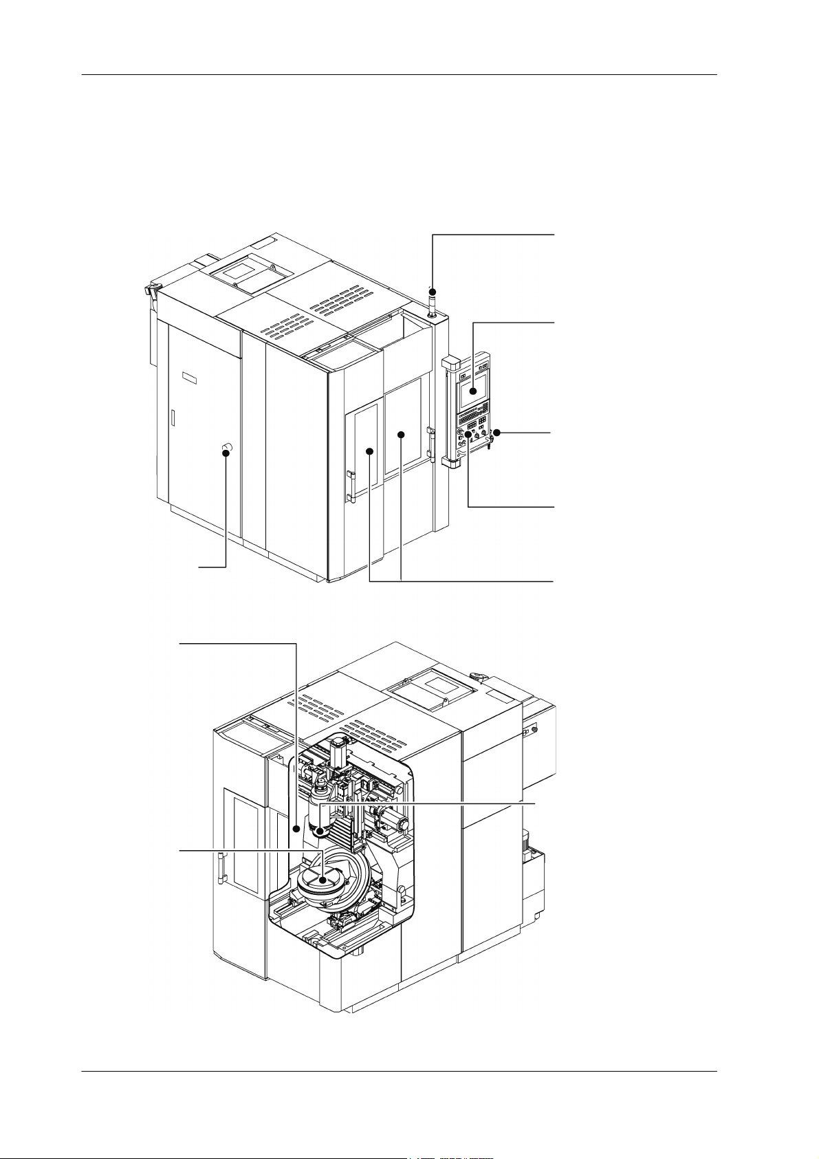
Signal lamp
Refer to chap. “6 BASIC
OPERATION”
Operation modes
Refer to chap. “6 BASIC OPERATION”
Tool magazine
operation panel
Refer to chap. “4 OPERATION
PAN EL”
Screen types
Refer to chap. “5 SCREENS”
Manual pulse generator
Refer to chap. “4 OPERATION
PAN EL”
Main operation panel
switches
Refer to chap. “4 OPERATION
PAN EL ”
Opening and
closing doors
Refer to chap. “6 BASIC
OPERATION”
Manual axis feed
Refer to chap. “7 AUTOMATIC
OPERATION”
Tur ning p ower
ON/OFF
Refer to chap. “6 BASIC
OPERATION”
Tool preparations
Refer to chap. “6 BASIC
OPERATION”
Automatic tool
change
Refer to chap. “7 AUTOMATIC OPERATION”
Workpiece preparations
Refer to chap. “6 BASIC
OPERATION”
1.1 Operation Route Map
Fig. 1-1:
29F-21E-2006 (en) MAKINO
Page 19
PREFACE 1-3
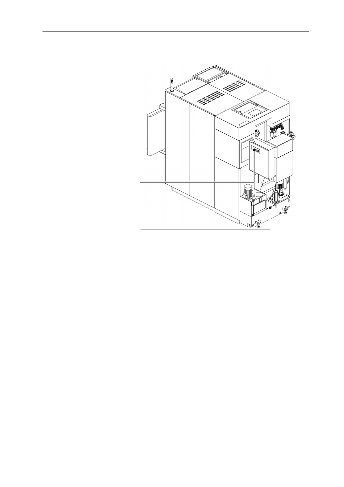
Lift-up chip conveyor operation panel
Refer to chap. “4 OPERATION PANEL”
Cutting fluid supply
Refer to chap. “6 BASIC OPERATION”
1.2 Important Information
General
- Do not attempt to modify the machine.
- Operation, maintenance, and inspection of this machine must be performed by staff who have received
technical training for the machine, training in machine hazards and their prevention, and safety training.
- Observe the laws, regulations, and other rules of the relevant national and local administrative agencies.
- This machine, including technical data and software, may be subject to the Japanese Foreign Exchange
and Foreign Trade Law.
Prior to any resale, transfer or re-export of controlled items, contact Makino to obtain any required authorization or approval.
- The specifications and design are subject to change without prior notice.
This Manual
- This manual is prepared for usage by experienced operators. For this reason, it does not include safety
precautions for operators who do not have mechanical or technical knowledge of machine operation,
programming, and maintenance.
- If the machine is operated by persons who are not native speakers of the language in this manual, the
customer must ensure that the operators receive complete safety training. Also, warning labels must be
affixed in a language that the operators can understand.
- The copyright for the entire content of this manual belongs to Makino Milling Machine Co., Ltd. The
copying, reproduction, or transfer of this manual, in whole or in part, without the express written permission of Makino Milling Machine Co., Ltd., is strictly prohibited.
MAKINO 29F-21E-2006 (en)
Fig. 1-2:
Page 20

1-4 PREFACE
- Illustrations and other details may differ from the actual machine due to the selected options, modified
specifications, or other reasons.
- Store the manuals needed for operation, maintenance, and inspection of this machine in a location
where they can be easily accessed by the operator.
- Be sure to perform periodic inspection and maintenance of the machine according to the periodic
maintenance manual or the legend plate to prevent breakdown of the machine.
Important Points for Work Safety
- Familiarize yourself with the safety precautions and functions before attempting to operate, maintain,
or inspect the machine.
- The points that the operator must observe when performing machine operation and maintenance vary
depending on the situation. All possible points cannot be covered in the content of this manual. Be sure
to fully understand the machine, and remain constantly aware of safety and the potential hazards while
doing work.
- If the safety devices or protective devices do not operate properly, stop operation of the machine and
notify the supervisor or manager. The supervisor or manager must immediately notify your authorized
Makino dealer or Makino service representative.
- When the machine is stopped due to an unknown cause, immediately contact the supervisor or manager, and wait for permission before restarting operation.
Keeping Machining Accuracy
- After installing the machine, to keep machining accuracy, conduct periodic inspection such as performing level adjustment. If the level of the machine changes, high-accuracy machining cannot be performed. In addition, normal machining cannot be performed if the machine vibrates.
- Especially, for approximately six months after installation, the level of the machine might change significantly until the foundation becomes stable.
- Depending on the condition of the foundation or the machine usage frequency, conduct inspection and
adjustment approximately every six months or every year.
1.3 Manuals and How to Use Them
Manuals Belonging to This Machine
Name Description
Instruction Manual This manual includes the basic information (overview, specifications)
needed for operation, practical operating procedures (operation),
and troubleshooting procedures.
Periodic Maintenance Manual This manual explains the intervals for periodic maintenance and
work that is required for maintaining optimum performance of this
machine.
Peripheral Device Manual This manual describes the operating procedures for the peripheral
devices connected to the machine body.
Parts Manual This manual provides the machine component part names and their
order numbers.
Professional 6 Operation Manual This manual describes the operating procedures and various func-
tions of the controller (Professional 6).
Professional 6 M Code List This manual describes the M codes of Professional 6.
Table 1-1: (1 / 2)
29F-21E-2006 (en) MAKINO
Page 21

PREFACE 1-5
Name Description
FANUC
Set of NC Manuals
Maintenance Manual (option) This manual describes the mechanisms of the machine and how to
Installation Manual (option) This manual describes the preparation, carry-in, and installation pro-
Other manuals for options These manuals describe the operating procedures for the optional
Notation Used in This Manual
See chapter “0 GENERAL SAFETY INSTRUCTIONS” for the description of used warning symbols.
These manuals describe the operating procedures for FANUC equipment.
perform the maintenance and adjustment work.
cedures for setup of the machine.
devices.
Table 1-1: (2 / 2)
1.4 General Contents
Chap. “2 SAFETY”
This chapter describes the safety devices and warning labels, work and operating precautions, and other
information for ensuring safety operation of the machine. Be sure to read this chapter before using the
machine.
Chap. “3 SPECIFICATIONS”
This chapter describes the basic configuration and specifications of the machine.
Chap. “4 OPERATION PANEL”
This chapter describes the main operation panel, manual pulse generator, and other details about the operation panels used in this machine.
Chap. “5 SCREENS”
This chapter provides an overview of the screens used in this machine.
Chap. “6 BASIC OPERATION”
This chapter describes machine power ON/OFF, door open/close, tool and workpiece preparation, manual
axis feed, and other manual operations required before machining.
Chap. “7 AUTOMATIC OPERATION”
This chapter describes the execution of automatic operation, automatic tool change operation, and similar
operations.
Chap. “8 TROUBLESHOOTING”
This chapter provides the basic troubleshooting information when the machine does not operate properly.
Chap. “9 INSTALLATION PREPARATION”
This chapter includes the dimensions required for machine carry-in and other operations.
MAKINO 29F-21E-2006 (en)
Page 22

1-6 PREFACE
29F-21E-2006 (en) MAKINO
Page 23

SAFETY 2-1
2SAFETY
2.1 Safety Precautions
- Disregarding the specific instructions or precautions included in this manual may result in serious injury
or death to the operators or surrounding workers, or damage to the machine.
- Never disable or remove any safety device. Operating the machine while the safety devices are disabled
may result in serious injury, death, or damage to the machine.
- Observe the safety precautions provided in this manual at all times and fully implement safety measures.
- Inspect and maintain the machine regularly to keep it in optimum operating condition. Do not run the
machine if it shows any signs of abnormal operation.
- The keys (release key for door switch, machine controller panel key, etc.) which are not necessary for
regular operation and maintenance must be removed from the machine and managed by supervising
personnel.
- The lubricating oil, cutting fluid, and other chemical substances used with the machine must be managed by supervising personnel.
- Workpiece materials such as magnesium and titanium may cause a fire if mishandled, so be particularly
careful when machining workpieces and handling cutting chips made from these types of materials.
2.1.1 Operator Checks
- Only qualified personnel who have adequate mechanical and technical knowledge are allowed to operate and maintain the machine.
- Only qualified electrical engineers may perform electrical work.
- Only qualified personnel may use a crane or forklift.
- Wear suitable work clothes whenever operating or maintaining the machine. Do not operate the machine while wearing loose-fitting clothes, a necktie, jewelry, or any other clothing or objects which may
become entangled with the moving parts of the machine.
- Tie up long hair, and wear a cap.
- Wear safety glasses, safety shoes, safety cap (including safety helmet), and safety gloves as needed.
Fig. 2-1:
- Protective gear should be worn to protect hearing when excessive noise may be generated during operation or maintenance.
- Never operate any machinery while under the influence of alcohol or drugs.
- The operator should be in proper physical condition. If the operator suffers from a condition that impairs judgment, it may result in serious injury or death.
2.1.2 Work Environment Checks
- Make sure the machine and surrounding area are fully lighted.
MAKINO 29F-21E-2006 (en)
Page 24

2-2 SAFETY
- Make sure the machine and surrounding area are tidy and clean at all times.
- Clean up any oil, cutting fluid, or chips scattered around the machine.
- When performing work at high locations, use a stable footstool or stepladder.
- Keep all flammable substances away from the work area.
- Maintain adequate working space.
2.1.3 Precautions for Potential Fire Hazards
Use the machine by following the precautions below to protect the machine equipment, plant, and surrounding environment from the danger of fire and to ensure the safety of operators.
When using cutting fluid, be sure to use a water-soluble cutting fluid (type A1).
There is no fire hazard when using water-soluble cutting fluids (except when using them with special materials).
Oil-based cutting fluids present a potential fire hazard.
- If an oil-based cutting fluid must be used due to unavoidable circumstances, be sure to observe the
precautions below.
- Do not run the machine in an unmanned operation mode.
- Install the proper fire-extinguishing equipment near the machine.
- Provide alarm devices to detect a fire, automatic fire-extinguishing devices, and other equipment to the
greatest extent possible.
- Do not create situations which may potentially start a fire.
• Machine under the proper cutting conditions.
• Perform proper tool management to prevent the occurrence of abnormal frictional heat and sparks.
• Do not allow chips to accumulate in the machining chamber.
• Check that a constant and full supply of cutting fluid is provided.
• Always clean up and organize the area around the machine, and do not place flammable objects in the
area.
Precautions for machining of flammable solids, resins, wood, and other flammable materials.
When machining flammable solids or other special materials, be sure to fully implement safety measures
after gaining a thorough understanding of the material properties. Be sure to also pay careful attention to
safety when machining resins, wood, and other materials.
When machining materials that generate dust and powder, be sure to provide equipment that takes into
account the danger of a dust explosion for certain material types.
Precautions for machining while blowing air.
Because air blowing has weak cooling performance, the chips that spray and fly out in the surrounding
area are extremely hot. Do not place flammable objects in the machining chamber or in the area surrounding the machine.
2.1.4 Confirmation of Machine Status
- Machine inspections and maintenance must be performed regularly to maintain optimum machining
accuracy and long-term performance, and increase machine operating efficiency.
- Confirm that all safety devices are functioning normally.
- Make sure the operator knows the location of the [Emergency Stop] switches to enable easy access in
the event of an abnormal or dangerous situation (refer to “2.3.1 [Emergency Stop] Switch”).
29F-21E-2006 (en) MAKINO
Page 25

SAFETY 2-3
- Check for any loose, damaged, or worn parts on the machine. Operating the machine in a condition in
which any of the parts has an abnormality may cause abnormal noises or damage to the machine.
- Check for any damaged piping or wiring. Operating the machine with the piping or wiring left damaged
may cause oil leakage, electrical shock, or fire.
- Use the most appropriate cutting tool, tool holder, retention knob, and workpiece, and make sure that
they are all secured firmly in place. Otherwise, the workpiece may fall or the tool may fly out, and this
may result in damage to the machine, serious injury, or death.
- Check that the tool numbers are registered correctly. Otherwise, the spindle may rotate at a speed outside the allowable range, the tool may fly out, and this may result in damage to the machine, serious injury, or death.
2.1.5 Pre-operation Checks
- Be sure that you fully understand the work procedures and precautions before operating and maintaining the machine. Never operate any machinery if you are unsure about any points.
- Check that the clothes you are wearing are suitable for operation.
- Perform periodic maintenance.
- Confirm that all safety devices are functioning properly before operating and maintaining the machine.
- Periodically back up the parameters when the machine was shipped and the program and offset data
that have been prepared by the customer. Makino is not liable for any program or offset data that is
corrupted or lost.
- Makino does not accept responsibility for any trouble caused by apparatus or programs prepared by
the customers, such as damage to workpieces or the machine.
- For details about replacement parts, contact your Makino service representative. Use of improper parts
may result in reduced machine performance or safety, damage to the machine, or operator injuries.
- Before entering inside the machine to perform work, be sure to confirm the escape procedure in the
event that you inadvertently become shut inside the machine.
- Perform the lock-out and tag-out procedures.
- Make sure the operator knows the location of the [Emergency Stop] switches for each device so that
they can be easily operated in the event of an abnormal or dangerous situation.
- Be sure to observe the information on the warning labels. Contact your Makino service representative if
a warning label comes off or becomes illegible.
- When handling a hazardous or toxic material (oils, cutting fluids, and other chemical substances), obtain
the safety data sheet (SDS), and follow the instructions. The safety data sheet (SDS) contains information about the safe handling of hazardous and toxic materials, and emergency measures.
- For the graphite specifications, do not let the dust collector collect anything other than graphite dust.
Failure to observe this precaution may result in a dust explosion. Also, it may damage the filter or cause
other malfunctions.
- For the graphite specifications, observe the following precautions to prevent health problems related to
the inhalation of graphite dust.
• After machining the workpieces, wait for the dust collector to remove airborne dust particles before
opening the operator door. If you open the operator door immediately after machining, the airborne
dust will disperse throughout the machining room.
• Wear a high-performance dust-proof mask when doing the following (particle collection efficiency of
99.9% or more is recommended).
- Opening and closing the operator door
- Performing an operation with the operator door open
- Replacing a tool in the tool magazine
- Handling dust
• Do not remove the dust car and chip bucket while the dust collector is operating. Otherwise, dust will
disperse in the surrounding area.
MAKINO 29F-21E-2006 (en)
Page 26
2-4 SAFETY
DANGER
Under Maintenance/
Inspection
Operator’s Name: xxxxx
Department: xxxxx
D
A
N
G
E
R
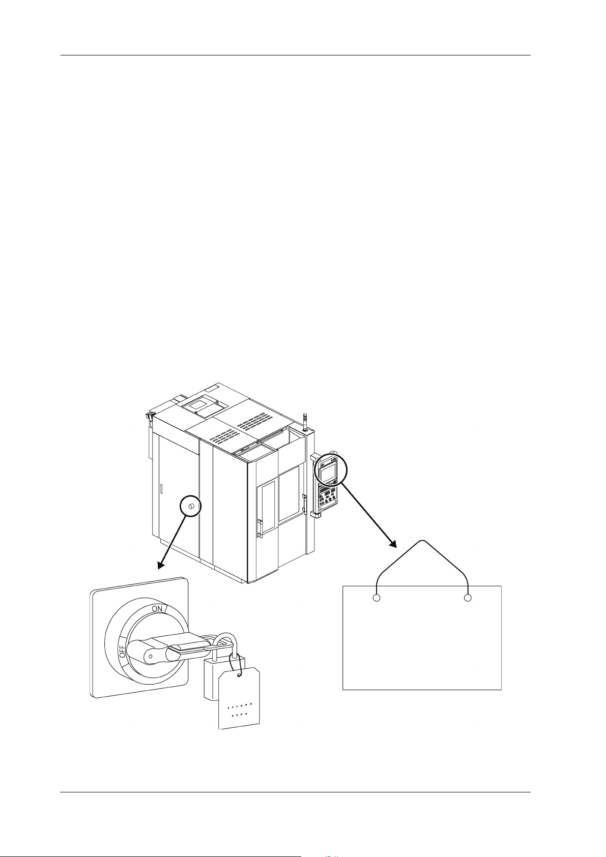
2.1.6 Implementing Lock-out and Tag-out
Lock-out consists of shutting down the power source to the machine or devices and locking it.
Example: .................... Set the main power switch to the “OFF” position and secure it using a padlock or a
lockout device such as a cover.
Tag-out consists of placing a warning tag to prevent anyone from turning ON the power.
Example: .................... Place a “Do Not Operate” or “Under Maintenance” sign with the operator’s name and
department and indicating that machine operation is prohibited on the main power
switch and main operation panel.
Lock-out/tag-out should be performed to prevent inadvertent operation and ensure operator safety.
- Performing lock-out/tag-out alone does not completely ensure operator safety. The operator must read
and thoroughly understand the work procedures and safety precautions, and always be aware of potential hazards.
Each operator should perform lock-out or tag-out by himself or herself. Perform this procedure before
starting the work, and release the lock and remove warning tag yourself after finishing work. Never release a lock and remove a sign without confirming with the operator or without the presence of the operator himself or herself.
Be sure to clearly define and implement the lock-out and tag-out procedures of your company.
Fig. 2-2: Implementing Lock-out and Tag-out
29F-21E-2006 (en) MAKINO
Page 27

SAFETY 2-5
2.1.7 During Work
- Turn OFF the power before performing maintenance of the machine. When work must be performed
with the machine power ON, confirm that all machine operations are completely stopped. Check that
any residual energy in the machine is completely discharged.
- Never go near the moving parts of the machine. If you must approach moving parts to perform maintenance, be sure to take adequate safety precautions. Inadequate attention to safety may result in death
or another serious accident.
- Always keep the doors and covers closed during operation. If you must work with the doors and covers
open, be sure to take ade quate safety precautions. Inadequate attention to safety ma y result in death or
another serious accident.
- If an operator gets trapped inside the machine, press the [Emergency Stop] switch regardless of whether the machine power is ON or OFF.
- If the machine is stopped by a power failure or power supply fault, turn OFF the machine power. If the
power is not turned OFF, the machine may start operating unexpectedly when the power is restored,
and this may result in serious injury, death, or damage to the machine.
- If the machine is stopped by a power failure or power supply fault, check that the parameter, program,
and offset data have not been corrupted. The machine may be damaged if it is operated using corrupted data.
- Be aware of the movement range of the machine and auxiliary components (each axis stroke, rotation
range, etc.), and keep all body parts clear of moving components.
- When two or more people are required for maintenance work, be sure to maintain clear communication
at all times to ensure operator safety. When performing work, be ready to press the [Emergency Stop]
switch at any time.
- Be sure to always pay attention to the safety precautions listed on the warning labels affixed to the machine (refer to “2.2 Warning Labels”).
- Do not operate the switches or change the circuits except for adjustment purposes. In particular, operating the machine with the interlock(s) or other safety devices or functions disabled is extremely dangerous and may result in death or damage to the machine.
- If a circuit or other component needs to be changed for adjustment purposes, be sure to return it to the
original setting after adjustment is completed.
- The optimum values for the NC parameters and machine parameters are set when the machine is
shipped. Do not change any parameter setting unless it is described in the manual. Also, be sure that
you fully understand the function of a parameter before attempting to change the parameter setting,
and return the parameter to its original setting after the work is completed. If you try to operate the
machine without the proper settings, the machine may operate unexpectedly, and this may result in serious injury, death, or damage to the machine.
- If the memory clear operation needs to be performed, be sure to contact your Makino service representative beforehand.
- If an alarm is triggered, eliminate the cause of the alarm using the appropriate procedure. If the remedy
procedure is unclear, contact your Makino service representative.
MAKINO 29F-21E-2006 (en)
Page 28

2-6 SAFETY
- Never climb onto the covers. This may deform the covers or result in injury.
- When using a stepladder or stool, it should be sturdy, safe, and have anti-slip surfaces.
- If any oils or cutting fluids get into your eyes, body, or on your skin surface, they may cause severe
health problems. Wear safety gloves, mask, safety glasses, and other safety equipment.
- Wear safety gloves whenever handling chips, tools, and workpieces.
- Protective gear should be worn to protect hearing when excessive noise may be generated during operation or maintenance.
- If lubricating oil, grease, cutting fluid, or other substances are spilled on the floor, it may result in slippage, causing injury. Wipe up any spilled fluids as soon as possible.
- Never touch a switch, button, or key while your hands are wet. Failure to observe this precaution may
result in electric shock.
- Some devices (motors, lighting equipment, valves, etc.) may become very hot while the machine is operating and remain hot soon after the power is turned OFF, so be careful to avoid burns.
- Do not subject the machine to sudden impact or jolts. This may cause the machine to perform an unexpected motion or result in damage to the machine.
- Do not use the machine for operation outside the specifications or exceeding the performance range.
This may cause the machine to perform an unexpected motion or result in serious injury, death, or damage to the machine.
- Use the most appropriate cutting tool, tool holder, retention knob, and workpiece, and make sure that
they are all secured firmly in place. Otherwise, the workpiece may fall or the tool may fly out, and this
may result in damage to the machine, serious injury, or death.
- Be careful that you do not leave objects such as tools or jigs inside the machine.
- Do not place the tools, workpiece, or other parts on an unstable location.
- When a lifting sling or attachment is necessary, verify that it is strong enough to support the weight of
the parts. Confirm that no one is close to the machine and the parts are well balanced, and be careful
not to hit to the machine.
- Never go under a load that is being lifted. While transferring the hoisted load, constantly pay careful attention to the hoisted load during the operation.
- Check that the tool numbers are registered correctly. Otherwise, the spindle may rotate at a speed outside the allowable range, the tool may fly out, and this may result in damage to the machine, serious injury, or death.
- Never insert hands or feet into the chip conveyor. They may be pulled in, and this may result in death or
another serious accident.
- For the graphite specifications, observe the following precautions to prevent health problems related to
the inhalation of graphite dust.
• After machining the workpieces, wait for the dust collector to remove airborne dust particles before
opening the operator door. If you open the operator door immediately after machining, the airborne
29F-21E-2006 (en) MAKINO
Page 29

SAFETY 2-7
dust will disperse throughout the machining room.
• Wear a high-performance dust-proof mask when doing the following (particle collection efficiency of
99.9% or more is recommended).
- Opening and closing the operator door
- Performing an operation with the operator door open
- Replacing a tool in the tool magazine
- Handling dust
• Do not remove the dust car and chip bucket while the dust collector is operating. Otherwise, dust will
disperse in the surrounding area.
2.1.8 Handling of Hazardous and Toxic Materials
Handlers of hazardous and toxic materials (such as oils and cutting fluid) must receive information, education, and training in accordance with the stipulations in JIS Z 7253 (revised March 2012)/ISO 11014: 2009.
Particular attention must be paid to the following points.
- Be sure that there is adequate ventilation in areas where hazardous and toxic materials are used.
- Hazardous and toxic materials must be handled and stored based on the handling procedures recommended by the manufacturer.
- Identify hazardous and toxic materials by affixing labels to their containers.
- Assign a person in charge to handle the hazardous and toxic materials, and provide education and
training in emergency response procedures and handling procedures.
- Before handling any hazardous or toxic material, be sure to check the safety data sheet (SDS). The safety
data sheet (SDS) contains detailed information on health and safety hazards, safe handling procedures,
and responses to emergency situations.
2.2 Warning Labels
Warning labels are affixed to machine parts that are potentially hazardous to warn operators about the
hazard and its level of danger and ensure the safety of operators.
The warning labels include symbols to indicate the source of the danger, signal words to indicate the level
of danger, and warning text to describe how to prevent the danger. When working at a location where a
warning label is affixed, make sure that you fully understand the warning label information and definitions
and follow the warning text that is provided. Failure to observe the information in the warning labels may
result in death or another serious accident or damage to the machine.
2.2.1 Signal Word Definitions
Signal words are divided into four classes based on the degree of expected risk.
See chapter “0 GENERAL SAFETY INSTRUCTIONS” for the description of used warning symbols.
MAKINO 29F-21E-2006 (en)
Page 30
2-8 SAFETY
2.2.2 Using Warning Labels
- Do not cover up or peel off the warning labels.
- Confirm that the operators and maintenance personnel are familiar with the language on the labels. If
labels in other languages are required, contact your Makino service representative.
- Check that all the information in the warning label is legible. If any portion of the warning text or symbol is not visible, clean by wiping with a soft cloth dipped in water or household cleanser. Do not use organic solvents or gasoline. These may damage the surface of the warning label.
- Replace the warning label if the information in the warning label is no longer visible. To obtain new
warning labels, contact your Makino service representative.
- If a part is replaced where a warning label was affixed, obtain a new warning label and affix it at the
same position as before on the new part. To obtain new warning labels, contact your Makino service
representative.
2.2.3 Information Contained in Warning Labels
The two types of warning labels are shown below.
- Labels with warning text and a warning mark
- Labels with a warning mark only
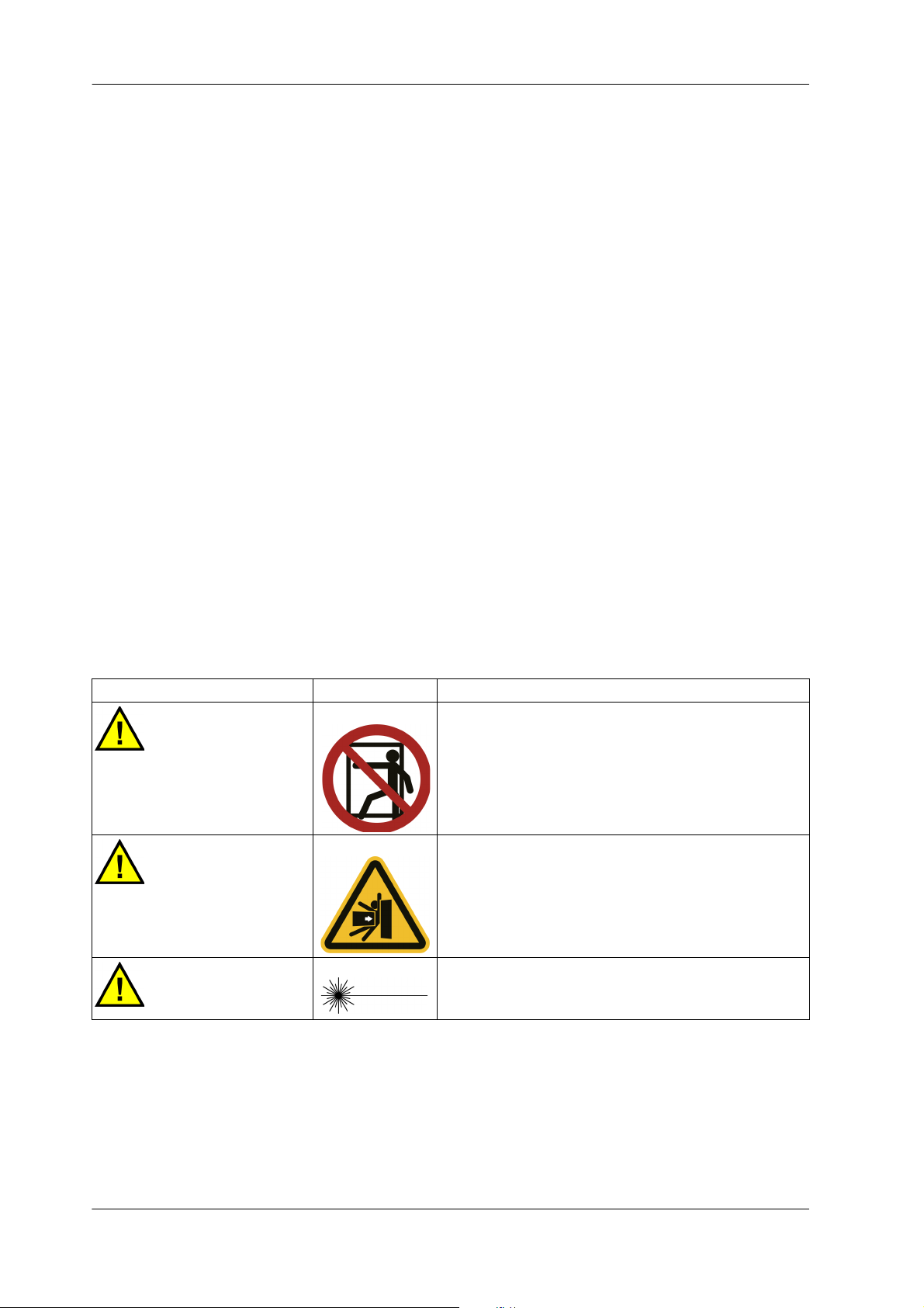
2.2.3.1 Warning Labels with Warning Text
Signal Word Symbol Description
DANGER
DANGER
CAUTION
This warning label is affixed to areas where entry is
prohibited.
This warning label is affixed to places where serious
injury, death, or another accident occurs by being
crushed, entangled, or pierced, or by falling.
Maximum output 1 mW, semiconductor laser
Class 2 laser product
Do not stare into the beam.
Table 2-1:
29F-21E-2006 (en) MAKINO
Page 31

SAFETY 2-9
2.2.3.2 Warning Labels with Warning Marks Only
Symbol Description
This warning label is affixed to parts where touching the internal high-voltage components may result in electrical shock.
Workers who are not qualified electrical engineers must not access the parts where this
warning label is affixed.
This warning label is affixed to parts that may become extremely hot.
Do not touch parts where this warning label is affixed. Be particularly careful immediately after operation because these parts are extremely hot at this time.
Table 2-2:
2.2.4 Warning Label Locations
The type of warning label and the location where the label is affixed to vary depending upon the machine
model.
Warning labels with warning marks only are affixed to various locations on the machine, and all affixing locations are not shown in the figure.
MAKINO 29F-21E-2006 (en)
Page 32

2-10 SAFETY
Serious Injury /
Death
Crush, Pinch,
Stab, Slip and Fall
Hazard
DANGER DANGER
DO NOT ENTER
Authorized
Personnel Only
CAUTION
DO NOT Stare
into Beam
Power 1 mW
Smeiconductor
Laser
Class 2 Laser
Product
(When an automatic non-con-
tact type tool measurement
device is included.)
2.2.4.1 Area around Operator Door
Fig. 2-3: Area around Operator Door
29F-21E-2006 (en) MAKINO
Page 33

SAFETY 2-11
Serious Injury /
Death
Crush, Pinch,
Stab, Slip and Fall
Hazard
DANGER DANGER
DO NOT ENTER
Authorized
Personnel Only
2.2.4.2 Area around Tool Magazine
Fig. 2-4: Area around Tool Magazine
MAKINO 29F-21E-2006 (en)
Page 34

2-12 SAFETY
2.3 Safety Devices
DANGER!
Never disable or remove any safety device.
Safety devices are installed on the machine to protect operators and maintenance personnel. The safety
devices also include ones that function on the condition that the operator observes the safety procedures.
2.3.1 [Emergency Stop] Switch
WARNING!
Make sure operators know the locations of all the [Emergency Stop] switches prior to performing machine operation or maintenance to enable use in an abnormal or dangerous
situation.
The machine goes to the following status when the [Emergency Stop] switch is pressed:
- Feeding of the axes is stopped immediately.
- Spindle rotation stops if it is rotating.
- The spindle is clamped if it has been unclamped.
- When orientation of the spindle has been performed, orientation is reset.
- When a tool is being changed or the tool magazine is operating, operation stops immediately (even
during motion).
- The chip conveyor in operation comes to an immediate stop.
- The hydraulic unit is stopped.
- The cutting fluid supply is stopped.
- Supply of the air blow inside the machining chamber is stopped (graphite specifications).
-The dust collector stops collecting dust (graphite specifications).
- Energizing of all solenoid valves is reset.
-The NC is reset.
Once the [Emergency Stop] switch is pressed, it is locked in the pressed position. The lock can be released
by turning the switch in the direction indicated by the arrow or pulling out the switch.
Then, pressing the [CONTROL POWER ON] switch cancels the emergency stop state.
For details about recovery procedures following machine operation stopped by the [Emergency Stop]
switch activation refer to chap. “8.2.1 Recovery from Emergency Stop Status”.
29F-21E-2006 (en) MAKINO
Page 35

SAFETY 2-13
Legend
[1] [Emergency Stop]
switch
2.3.1.1 [Emergency Stop] Switch Installation Location (Machine Body)
Fig. 2-5: [Emergency Stop] Switch Installation Location (Machine Body)
MAKINO 29F-21E-2006 (en)
Page 36

2-14 SAFETY
Legend
[1] [Emergency Stop]
switch
2.3.1.2 [Emergency Stop] Switch Installation Location (Large Capacity Tool
Magazine)
Fig. 2-6: [Emergency Stop] Switch Installation Location (Large Capacity Tool Magazine)
2.3.2 Door Switch
The door switch is a device for detecting and controlling the status of doors.
29F-21E-2006 (en) MAKINO
Page 37

SAFETY 2-15
Legend
[1] Door switch
Legend
[1] Door switch
2.3.2.1 Door Switch Installation Location (Machine Body)
Fig. 2-7: Door Switch Installation Location (Machine Body)
2.3.2.2 Door Switch Installation Location (Disk Type Tool Magazine 21-tool/40-tool)
Fig. 2-8: Door Switch Installation Location (Disk Type Tool Magazine 21-tool/40-tool)
MAKINO 29F-21E-2006 (en)
Page 38

2-16 SAFETY
Legend
[1] Door switch
2.3.2.3 Door Switch Installation Location (Large Capacity Tool Magazine)
Fig. 2-9: Door Switch Installation Location (Large Capacity Tool Magazine)
2.4 Work Hazards
The following tables list examples of hazardous actions and situations during machine operation and
maintenance and examples of the resulting accidents and incidents that may occur.
The points that the operator must observe when performing machine operation and maintenance vary
depending on the situation. All possible points cannot be covered in the content of this manual. Therefore,
be sure to fully understand the machine, and remain constantly aware of safety and the potential hazards
while doing work.
29F-21E-2006 (en) MAKINO
Page 39

SAFETY 2-17
Improper operation may result in death or damage to the machine.
2.4.1 Area Surrounding Machine
Action/Situation Result
Tripping over piping/wiring Falling
Operator working on oily floor Fall, bone fracture, injury
Bringing an open flame into the area Fire, burn
Improper handling of chemical substances Skin lesions, eye injury, or respiratory problems
Table 2-3:
2.4.2 Electrical System
Action/Situation Result
Performing inspection or maintenance operation
without turning OFF the power
(Refer to REMARKS.)
Touching a device with residual voltage
(Refer to REMARKS.)
Miswiring Breakdown of the machine, abnormal operation,
Loose screw in terminal block or other location Breakdown of the machine, abnormal operation,
Machine controller door or junction box cover is
left open
Touching switches with wet hands Electrical shock
Damage to wiring on floor Electric leakage, breakdown of the machine, abnor-
Operation or maintenance by non-qualified personnel
REMARK Prior to performing maintenance of the servo amplifiers, spindle amplifiers, and inverters,
turn OFF the main power and confirm that the LED which indicates charging (red) for each
amplifier and inverter is off.
Electric shock, breakdown of the machine, abnormal operation, fire
Electrical shock
fire
fire
Electric leakage, breakdown of the machine, abnormal operation, fire
mal operation, fire
Breakdown of the machine
Table 2-4:
REMARK High voltage current flows through components inside the junction box.
REMARK High voltage current continues to flow on the primary side of the main power switch even
after the main power is turned OFF.
REMARK Electrical current continues to flow to lamps and outlets in the machine controller even af-
ter the main power is turned OFF.
MAKINO 29F-21E-2006 (en)
Page 40

2-18 SAFETY
2.4.3 Parameters
Action/Situation Result
Changing NC/machine parameters not listed in
manual
Forgetting to return the parameter to its original
value after adjustment
Injury or death, workpiece damage, breakdown of
the machine
Injury or death, workpiece damage, breakdown of
the machine
Table 2-5:
2.4.4 Inside the Machining Chamber
Action/Situation Result
Working without performing lock-out and tag-out Injury or death, damage to the machine
Operator entering machining chamber without
turning OFF the power
Operator entering machining chamber with safety
devices or functions disabled
Getting near the operating range of an axis when
the power is turned ON or during axis feeding
Replacing the gravity axis motor without using the
fixing jig
Rotating spindle prior to cleaning of tapered section while operator door is open
Rotating unbalanced tool at high speed while operator door is open
Hand or other body part becomes wedged in operator door when it is opened or closed
Operator touching rotating spindle Hands or fingers cut off, body part becomes entan-
Touching a feed axis motor Burns
Workpiece has not been clamped Injury, bone fracture, bruises
Entering machining chamber when table is inclined Injury, bruises
Touching an operating ATC shutter Injury
Operator becomes entangled in chip conveyor Body part pulled in, resulting in injury or death
Climbing on top of covers Fall, bone fracture, injury
Climbing on top of the movable covers, inserting
your hand into the gaps
Operator working on oily floor Fall, bone fracture, injury
Touching the wipers Cuts to hands
Operator touching bladed tools Cuts, injuries to hands
Holding a heavy tool Strained back, hands become wedged between
Injury or death
Injury or death
Injury, bone fracture, bruises
Injury or death, damage to the machine
Injury or death, damage to the machine
Injury or death, damage to the machine
Injury, bone fracture, bruises
gled, or other serious injury or death
Injury, bruises
tool and object
Table 2-6: (1 / 2)
29F-21E-2006 (en) MAKINO
Page 41

SAFETY 2-19
Action/Situation Result
Operator being struck by chips, cutting fluid, or
dust scattered during machining
Operator being splashed by cutting fluid dripping
from ceiling in machining chamber
Operating machine while there is abnormal vibration or abnormal noise
Operating machine with a tool incorrectly clamped Injury or death, damage to the machine
Opening the operator door and entering the machining chamber while mist is not being collected
Cleaning without wearing protective gloves Cuts to hands
Opening the operator door or entering the machining chamber while dust is not being collected
Entering the machining chamber without wearing a
dust-proof mask Respiratory problems
Fastening tools or implementing other work during
spindle orientation.
Inhaling dust Respiratory problems
Damage to eyes, cuts or burns to skin
Damage to eyes, skin irritation
Damage to the machine
Respiratory problems
Respiratory problems
Respiratory problems
Injury, bone fracture, bruises
Table 2-6: (2 / 2)
2.4.5 Tool Magazine
Action/Situation Result
Working without performing lock-out and tag-out Injury or death, damage to the machine
Operator entering the tool magazine without turning OFF the power
Operator entering the tool magazine with the safety devices and functions disabled
Manually changing tools by entering inside the tool
magazine
Performing T command or tool change while tool
blade or tool is mounted incorrectly
Tool number is registered incorrectly Damage to the machine
Operator inserting hands into tool magazine during tool magazine operation
Touching the tool magazine motor Burns
Operator working on oily floor Fall, bone fracture, injury
Operator touching bladed tools Cuts, injuries to hands
Holding a heavy tool Strained back, hands become wedged between
Hand or other body part becomes wedged in tool
magazine door when it is opened or closed.
Leaving a safety guard or maintenance cover
opened or removed
Injury or death
Injury or death
Injury or death
Injury or death, damage to the machine
Cuts, bone fracture of hands
tool and object
Injury, bruises
Injury
Table 2-7: (1 / 2)
MAKINO 29F-21E-2006 (en)
Page 42

2-20 SAFETY
Action/Situation Result
Holding or carrying a removed cover Injury or machine damage due to dropping of cov-
er
Performing cleaning or maintenance while a tool is
stored in the tool magazine
Cleaning without wearing protective gloves Cutting or stabbing of hand
Table 2-7: (2 / 2)
Cutting or stabbing of hand or body
2.4.6 Cutting Fluid Supply Unit/Chip Disposal Device/Cutting Fluid Temperature Controller/Dust Collector (Graphite Specifications)
Action/Situation Result
Working without performing lock-out and tag-out Injury or death, damage to the machine
Inserting hands or feet into conveyor or tank without turning OFF the power
Touching part or component immediately after operation
Operator touching moving parts when chip discharge outlet cover is removed
Stepping on a tank that is not fixed Fall, bone fracture, injury
Operating with low levels of cutting fluid Fire, damage to the machine
Touching cutting fluid or chemical additives Skin irritation
Touching chips Cuts, injuries, burns to hands
Replacing the filter without prior cleaning Cuts, injuries to hands
Inhaling large quantities of cutting fluid mist Respiratory organ damage
Mixing different brands of oils Breakdown of the machine
Failing to properly clean or collect flammable cutting chips or sludge
Mixing cutting chips made from different materials Fire
Performing operation without wearing protective
gloves
Inhaling dust Respiratory problems
Serious injury due to body part becoming entangled, or cuts to hands and feet
Burns
Serious injury due to body part becoming entangled
Fire
Cuts, injuries to hands
Table 2-8:
2.4.7 Temperature Controller
Action/Situation Result
Touching part or component immediately after operation
Oil temperature exceeds flash point.
Flash point of Makino Spindle Lubricant: 95°C
Table 2-9: (1 / 2)
29F-21E-2006 (en) MAKINO
Burns
Fire
Page 43

SAFETY 2-21
Action/Situation Result
Changing filters without reducing the internal pressure
Performing operations without safety gloves, mask,
and other protective gear
Mixing different brands of oils Breakdown of the machine
Table 2-9: (2 / 2)
Injury or death, damage to the machine
Damage to eyes, skin irritation, accidental ingestion, or respiratory organ damage
2.4.8 Hydraulic Unit
Action/Situation Result
Working without performing lock-out and tag-out Injury or death, damage to the machine
Operator working on oily floor Fall, bone fracture, injury
Hand or other body part becomes wedged in tool
magazine door when it is opened or closed.
Leaving a safety guard or maintenance cover
opened or removed
Touching part or component immediately after operation
Oil temperature exceeds flash point.
Flash point of standard hydraulic oil: Approximately
200°C
Changing filters without reducing the internal pressure
Performing operations without safety gloves, mask,
and other protective gear
Mixing different brands of oils Breakdown of the machine
Injury, bruises
Injury
Burns
Fire
Injury or death, damage to the machine
Damage to eyes, skin irritation, accidental ingestion, or respiratory organ damage
Table 2-10:
2.4.9 Pneumatic Unit
Action/Situation Result
Removing the pneumatic unit source piping on the
machine side or disassembling the primary-side
line filter without shutting of the air supply from
the factory facilities
Removing the pneumatic unit source piping on the
machine side or disassembling the primary-side
line filter without releasing the residual pressure in
the air piping (inside the air circuit)
MAKINO 29F-21E-2006 (en)
Injury due to flying off of parts or impact
Injury due to flying off of parts or impact
Table 2-11:
Page 44

2-22 SAFETY
2.4.10 Splash Guard
Action/Situation Result
Working without performing lock-out and tag-out Injury or death, damage to the machine
Operator entering splash guard with the safety devices and functions disabled
Operating the machine with the covers removed Injury or death
Holding or carrying a removed cover Injury or machine damage due to dropping of cov-
Operator working on oily floor Fall, bone fracture, injury
Operator working at elevated locations Fall, bone fracture
Table 2-12:
Injury or death
er
2.4.11 Other Peripheral Equipment
Action/Situation Result
Performing operation without turning OFF the
power
Injury or death, electric shock
Table 2-13:
2.5 Occupational Health and Safety Management
2.5.1 Safety Device Inspection
Perform periodic maintenance and inspection of the safety devices used on this machine in order to ensure that they continue to function normally. Make sure that all maintenance staff fully understand the
types of safety devices, functions, and locations described in “2.3 Safety Devices” before performing any
maintenance work.
Before starting operation or maintenance work, inspect the safety devices, and if any are not functioning
properly, abort machine operation.
2.5.2 Noise
The noise level of the machine is shown below.
- Noise level: 80 dB maximum (A-weighted sound level)
These values are measured values at full operation (maximum rotation of the spindle without machining a
workpiece) with the safety guards and covers correctly mounted and all doors closed.
29F-21E-2006 (en) MAKINO
Page 45

SAFETY 2-23
CAUTION!
When a workpiece is machined, noise at 80 dB or higher may occur under certain customer cutting conditions. When performing work near the machine during machining, be sure
to wear ear protection and other equipment to ensure that your health is not harmed.
Performing work without wearing ear protection may lead to hearing loss.
REMARK The above noise level is measured at a location that is a distance of 0.5 m from the ma-
chine and a height of 1.2 m above the floor.
2.5.3 Personal Protective Equipment
When conducting installation, operation, and maintenance work on the machine, be sure to protect your
body from the following potential hazards.
- Mechanical hazards
- Hazardous and toxic materials
-Heat
-Noise
Be sure to always use protective equipment to protect your body from these hazards.
Some examples of protective equipment are shown below.
Protected
Body Part
Head Bruises and cuts, falling from
Eyes, nose,
mouth,
face
Eyes Laser beam Laser safety goggles Work performed with the eyes at
Ears Noise Earplugs Work where the environment con-
Hands Cuts, burns, and adhesion of
Feet Bruises Safety shoes Handling and transporting of heavy
Torso Falling from high locations Safety belt Work at locations 2 m or higher
Hazard Type Protective
Equipment
Work cap, Helmet - Work where parts or other objects
high locations
- Flying out of dust, chips,
chippings, and other substances
- Splashing of mist, lubricants, grease, and other oils
chemical substances
Protective goggles,
dustproof mask
Protective gloves,
heat-resistant gloves,
chemical-resistant
gloves
Work Requiring Protective
Equipment
may fall on the head
- Work where the head may get hit
- Work at locations 2 m or higher
Work where objects may spray or fly
out
around the same height as the laser
beam
stantly generates noise above the
stipulated level
Work where the hands must be protected
objects
Table 2-14:
MAKINO 29F-21E-2006 (en)
Page 46

2-24 SAFETY
WARNING!
Even when wearing laser safety goggles, do not look directly into the laser beam or indirectly by reflecting the beam on a mirror surface.
Use laser safety goggles to protect the eyes from the dangers of accidentally looking into
the laser beam and scattered laser beams.
2.5.4 Disposal of Waste Products
2.5.4.1 Disposal of Waste Oil, Waste Fluids, and Waste Materials
Dispose of any chips, graphite dust or liquids such as cutting fluid, grease, hydraulic oil and lubricant that
are discharged during operation of this machine in accordance with the laws, regulations, and ordinances
established in your country.
Also, separate and dispose of recyclable materials properly.
2.5.4.2 Disposal of This Machine
When disposing of this machine or its parts, disassemble and dispose of them in accordance with the laws,
regulations, and ordinances established in your country.
Also, separate and dispose of recyclable materials properly.
29F-21E-2006 (en) MAKINO
Page 47

SPECIFICATIONS 3-1
3 SPECIFICATIONS
3.1 Machine Basic Specifications
Travel X-axis × Y-axis × Z-axis 350 × 300 × 250 mm
B-axis 180° (−180° to 0°)
C-axis 360°
Tabl e Pallet working area 300 mm
Maximum table loading capacity 75 kg
Spindle Spindle speed 300 to 30000 1/min
Spindle taper hole HSK-E50
Feed rate Rapid feed rate X-/Y-/Z-axes 60000 mm/min
B-axis 36000 deg/min
C-axis 54000 deg/min
Cutting feed rate X-/Y-/Z-axes 1 to 60000 mm/min
B-axis 1 to 36000 deg/min
C-axis 1 to 54000 deg/min
Machine size Height 2300 mm
Mass 4600 kg
Table 3-1:
REMARK The values other than the spindle speed are for the standard specifications. For special
specifications, refer to the catalog or specifications published by Makino.
REMARK For details about power source requirements, refer to chap. “9 INSTALLATION PREPARA-
TION”.
3.2 Machine Primary Components
REMARK The layout and configuration of each unit varies depending on the machine specifications
and options.
MAKINO 29F-21E-2006 (en)
Page 48

3-2 SPECIFICATIONS
Legend: See below.
Fig. 3-1: Example of Machine Primary Components
1. Spindle
The spindle is mounted on the Z-axis slider and moves in the Z-axis direction. The spindle rotates by
29F-21E-2006 (en) MAKINO
Page 49

SPECIFICATIONS 3-3
a built-in AC motor.
Direction of spindle rotation: When viewed from above the spindle, clockwise (CW) is the forward rotation direction and counterclockwise (CCW) is the reverse rotation direction.
The cooling/lubrication method for the spindle differs depending on the spindle specifications.
Cooling Method Lubrication Method
Spindle core cooling/Jacket cooling Oil air lubrication
Table 3-2:
2. Feed Axis
The feed axis consists of the X-axis, Y-axis, and Z-axis, and it is driven by the servomotor and ball
screws.
3. Ta bl e
The table consists of the B-axis (inclined axis) and the C-axis (rotating axis), and it is driven by the DD
motor. Each of the B-axis and C-axis includes a clamp mechanism.
4. Automatic Tool Changer (ATC)
Motion of the spindle to the tool change position of the tool magazine automatically changes the
spindle-clamped tool with the tool in the tool magazine. The tool magazine has a disk type. A large
capacity tool magazine is an option.
5. Temperature Controller
The temperature controller feeds cooling oil to the machine for absorbing the heat generated during
the machining process.
6. Hydraulic Unit
The hydraulic unit is of a pressure accumulation type, supplying hydraulic oil at a constant pressure to
the spindle.
7. Air Unit
The air unit performs cleaning and depressurization of the air supplied to the machine.
8. Chip Disposal Device/Cutting Fluid Supply Unit (Other than Graphite Specifications)
The cutting fluid supply unit discharges cutting fluid for cooling the workpiece and tool and for cleaning the machining chamber. The collected chips are discharged outside the machine by the lift-up
chip conveyor.
9. Dust Collector (Graphite Specifications)
The dust collector reduces the pressure inside of the machining chamber and collects airborne dust.
Dust and chips will fall on both sides of the Y-axis cover and be discharged to the chip bucket. The
collected dust is separated by a filter and collected in the dust car at the bottom of the dust collector.
10. Controller
The NC unit executes NC programs and controls the feed axis servomotor and spindle drive motor.
The machine controller (MTC) manages the tool data and workpiece data for performing overall control of the machine.
MAKINO 29F-21E-2006 (en)
Page 50

3-4 SPECIFICATIONS
Legend
[1] Saddle
[2] Column
[3] Bed
[4] Table
[5] Spindle head
[6] Spindle head base
3.3 Axis Configuration
Fig. 3-2: Axis Configuration
29F-21E-2006 (en) MAKINO
Page 51

SPECIFICATIONS 3-5
Legend
[1] Main operation panel [5] Cumulative operation hour meter (option)
[2] Tool magazine operation panel [6] Lift-up chip conveyor operation panel
(other than graphite specifications)
[3] Manual pulse generator
[4] “Main Power” switch [7] Signal lamp (option)
3.4 Operation Unit and Display Unit
Fig. 3-3: Operation Unit and Display Unit
MAKINO 29F-21E-2006 (en)
Page 52

3-6 SPECIFICATIONS
Legend
[8] Power switch (synchronized with machine power ON/OFF)
Fig. 3-4: Operation Unit and Display Unit
(When the Machine Is Equipped with a Large Capacity Tool Magazine)
29F-21E-2006 (en) MAKINO
Page 53

OPERATION PANEL 4-1
4OPERATION PANEL
4.1 Main Operation Panel
4.1.1 Switches and Panels on Main Operation Panel
Fig. 4-1: Switches and Panels on Main Operation Panel
MAKINO 29F-21E-2006 (en)
Page 54

4-2 OPERATION PANEL
No. Name Shape Description
[1] [CONTROL POW-
ER ON]
[POWER OFF] This turns OFF the control power, and then after a certain time
[2] [SPINDLE
ORIENTATION]
[3] [SPINDLE START] The spindle starts operation at the rotation speed (S code com-
[SPINDLE STOP] The spindle stops.
This turns ON the control power. The switch turns on while the
control power is ON. However, if the machine changes to an
emergency stop state, the switch turns off even if the control
power is turned ON.
has passed, it turns OFF the main power.
- When the [POWER OFF] switch is pressed, the switch lamp
blinks until the main power is turned OFF.
If the [POWER OFF] switch is pressed again while the switch
lamp is blinking, the operation is canceled, and the control
power and main power are not turned OFF.
The spindle is stopped (orientation) at a predetermined rotation
phase.
- The switch turns on when the spindle orientation is completed.
mand) and direction that were specified immediately before.
- This button is enabled irrespective of the operation mode.
- After the power is turned ON or the spindle is stopped by an
M code, operation always starts in the forward direction. Operation starts again in the same direction after it has been
stopped by the [SPINDLE STOP] switch.
- This button is enabled irrespective of the operation mode.
- Pressing this switch during automatic operation activates the
Feed Hold status for the machine.
[4] One-touch function buttons
[AUTO ZERO] The basic axes (X-axis, Y-axis, Z-axis, C-axis, and B-axis) are re-
turned to their reference positions. The tool magazine axes will
not be moved to their respective reference positions.
- After spindle rotation and supply of cutting fluid are stopped,
each axis is moved to its retracted position for reference position return in rapid feed mode, then the reference position return operation is performed.
[SET UP POS RET] After spindle rotation and supply of cutting fluid are stopped, the
Z-axis moves to the reference position, and then the X-axis and
Y-axis move to the setup position.
The setup position can be set to any position using the machine
parameters below (Each is set to “0” at shipping).
X-axis: Machine parameter No. 00002-00
Y-axis: Machine parameter No. 00002-01
Table 4-1: (1 / 6)
29F-21E-2006 (en) MAKINO
Page 55

OPERATION PANEL 4-3
No. Name Shape Description
[4] [SPEC TL CHG] Spindle rotation and supply of cutting fluid are stopped, and the
tool set as the specified tool is mounted to the spindle using the
automatic tool change operation.
Any specified tool can be set using the machine parameter below (This is set to “0” at shipping).
Machine parameter No. 00010-00
[TOOL RETRACT] This moves the tool in the retract direction.
[5] NC function/machine function switches
[BLOCK SKIP] This button enables/disables the block skip function.
- When the Block Skip function is enabled (switch is turned on),
blocks in the program with a “/” (slash) at the beginning are
ignored.
[Eco] This button turns Eco mode on (switch is turned on) or off (switch
is turned off).
[OPTIONAL STOP] This button enables/disables the optional stop function.
- When the optional stop function is enabled (switch is turned
on), a program is stopped by the M1 specified in the program.
The Cycle [START] switch lamp blinks while the operation is
suspended by M1.
To restart the program, press the Cycle [START] switch.
[SINGLE BLOCK] This button enables/disables the single block function.
- When the single block function is enabled (switch is turned
on), the program stops the machine each time a block is executed (spindle rotation and supply of cutting fluid are not
stopped).
To restart the program, press the Cycle [START] switch.
- If the switch was pressed during operation, the machine is
stopped after the block being executed is completed.
[LIGHTING] This turns the lighting on (switch is turned on) or off (switch is
turned off).
- The lighting can also be turned on by the M736 command and
turned off by the M737 command.
[AIR BLOW] This switch turns the air blow function on (switch is turned on) or
off (switch is turned off).
- The air blow function can also be turned on by the M7 command and stopped by the M756 command.
Table 4-1: (2 / 6)
MAKINO 29F-21E-2006 (en)
Page 56

4-4 OPERATION PANEL
No. Name Shape Description
[5] [NOZZLE COOL-
ANT]
(other than
graphite specifications)
[DUST COLLECTOR]
(graphite specifications)
[COOLANT
PAUSE]
This turns the nozzle coolant on (switch is turned on) or off
(switch is turned off).
- The nozzle coolant can also be turned on by the M8 command
and stopped by the M9 or M890 command.
- Cutting fluid cannot be discharged when the operator door is
open.
- This switch cannot be used with the graphite specifications.
NOTICE! Do not discharge cutting fluid when a tool is not
clamped in the spindle. Failure to observe this
precaution may result in a breakdown of the machine.
This turns the dust collector on (switch is turned on) or off (switch
is turned off).
- The dust collector can also be turned on by the M413 command and stopped by the M412 command.
- This switch cannot be used with models other than graphite
specifications.
When this is turned on (switch is turned on), the discharge of all
cutting fluid is temporarily stopped. When this is turned off
(switch is turned off), supply of cutting fluid that was temporarily
stopped is restarted.
- The cutting fluid can also be suspended by the M312 command and restarted by the M313 command.
- Cutting fluid cannot be discharged when the operator door is
open.
- For the graphite specifications, the air blow will stop.
[6] “Spindle
Override”
[7] “Feed Rate
Override”
NOTICE! Do not discharge cutting fluid when a tool is not
clamped in the spindle. Failure to observe this
precaution may result in a breakdown of the machine.
This switch sets an override for a specified spindle speed.
- However, the spindle override speed cannot exceed the maximum rotation speed.
- In the cases below, the spindle override is fixed at 100%.
• When M59 (Spindle Speed Override Disable) is executed
• During a tapping cycle by G84
This switch sets an override for a cutting feed rate specified during automatic operation. This specifies the override for the jog
feed rate that set in Manual mode.
- In the cases below, the feed rate override is fixed at 100%.
• When M49 (Feed Rate Override Disable) is executed
• During a tapping cycle by G84
- When M132 (Feed Rate Override 100% or Less) is specified, an
override that exceeds 100% is invalid.
Table 4-1: (3 / 6)
29F-21E-2006 (en) MAKINO
Page 57

OPERATION PANEL 4-5
No. Name Shape Description
[8] [+][−]
“Direction
Selection”
Switches
This switch is used to perform the operations below.
- Perform jog feed or manual reference position return in Manual mode
- Perform maintenance operation of devices in maintenance
mode
[9] “Rapid Traverse
Override”
[10] Cycle [START] This starts automatic operation based on the NC program.
[11] [FEED HOLD] This stops the NC program (feed hold stop).
[12] [DOOR LOCK RE-
LEASE]
This switch sets the override in rapid feed mode or reference position return mode.
- It is limited to 15% for all axes in non-measurement modes for
workpiece automatic measurement and tool length measurement.
- When the rapid traverse speed limit function is turned on, an
icon appears in the Info Header, and the rapid traverse override is limited to 25%.
This is also used to restart a program that was stopped by the
[FEED HOLD] switch or the single block function.
- The switch is turned on while a program is running.
- This is enabled for starting the following: Memory mode, MDI
mode, DNC operation mode, External Input mode, One-touch
function, measurement by screen operation, tool calling operation.
- The switch is turned on while the program is stopped.
- If the switch is pressed during operation, the program stops,
and the machine changes to the status shown below.
• The axes are decelerated and come to a stop.
• M, S, and T functions continue operation, and they are
stopped when operation is completed.
• Spindle rotation and supply of cutting fluid continue.
This is used to open the operator door or the tool magazine
door.
- Open the operator door or the tool magazine door while holding down this switch.
- If the door lock release conditions are not met, the door cannot be opened even if the switch is pressed (when the operator door cannot be opened, the corresponding message is
displayed in the operation screen).
Table 4-1: (4 / 6)
MAKINO 29F-21E-2006 (en)
Page 58

4-6 OPERATION PANEL
No. Name Shape Description
[13] [TOOL UNCLAMP] This is used to clamp and unclamp the spindle tool.
If a tool is clamped in the spindle, holding down the switch will
unclamp the spindle tool (switch is turned on).
To clamp a tool, insert a tool with the spindle unclamped, and
then press the switch (switch is turned off).
- This switch is enabled while the operator door is open and
Manual mode is selected.
- After clamping a tool, set the T number.
CAUTION!
Be careful that the tool does not drop when the
[TOOL UNCLAMP] switch on the main operation
panel is pressed.
[14] [Emergency Stop]
switch
[15] Operation mode selection buttons
[MEMORY] This switches the operation mode to Memory mode (switch is
[EDIT] This switches the operation mode to Editor mode (switch is
[MANUAL] This switches the operation mode to Manual mode (switch is
This switch is used to apply an emergency stop to the machine.
When this switch is pressed, all machine operations are stopped.
Once this switch is pressed, it is locked in this position. The lock
can be released by turning the switch in the direction indicated
by the arrow or pulling out the switch.
Recovery from emergency stop status: chap. “8.2.1 Recovery
from Emergency Stop Status”
turned on).
If Memory mode is selected and the Cycle [START] switch is
pressed, automatic operation is started for the NC program that
was found by search.
turned on).
This switch is used to perform the operations below.
- Program editing/search
- Saving programs from external input/output device to NC
memory
- Output of programs to external input/output device
- Setting of DNC schedule operation
- M198 (subprogram call from external I/O device) setting
turned on).
When Manual mode is selected, the manual operation screen is
displayed.
The following operations can be performed in Manual mode.
- Jog feed: The axis selected on the screen is moved to a userselected position using the [+] and [−] switches.
- Handle feed: The axis selected by the manual pulse generator
is moved to a user-selected position using the handle.
- Manual reference position return: The selected axis is moved
to a user-selected position by pressing the [REF Mode] button
and using the [+] and [−] switches.
Table 4-1: (5 / 6)
29F-21E-2006 (en) MAKINO
Page 59

OPERATION PANEL 4-7
No. Name Shape Description
[15] [MDI] This switches the operation mode to MDI mode (switch is turned
on).
This is used to manually enter a program and perform simple operations such as axis movement or M command, S command, or
T command operation.
- Programs that were executed in MDI mode are saved to the
MDI history of the program screen.
[16] MDI panel The MDI panel can be used for operations such as data input and
screen selection.
For details about the MDI panel, refer to “4.1.2 MDI Panel”.
[17] LCD panel This is a 15-inch touch panel type LCD screen.
Table 4-1: (6 / 6)
Other assignable switches
Name Shape Description
[COOLANT BASE]
(other than graphite specifications)
This turns the base coolant on (switch is turned on) or off (switch is
turned off). However, base coolant that is started in coordination
with machining cannot be stopped manually.
- The base coolant can also be turned on by the M754 command
and stopped by the M757 command.
- Cutting fluid cannot be discharged when the operator door is
open.
Table 4-2:
REMARK For details on how to allocate function to the switch on the main operation panel, refer to
the “Professional 6 Operation Manual”.
4.1.1.1 One-touch Function Operation Procedure
NOTICE! The operation of One-Touch function may include feed axis movement.
Confirm that the spindle and the workpiece do not interfere with each other.
Procedure
1. Press the one-touch function switch on the main operation panel or one-touch button on the function screen.
- The selected switch is illuminated.
2. Press the Cycle [START] switch on the main operation panel.
- When the Cycle [START] switch on the main operation panel is pressed, the operation starts.
- To stop halfway, press the [FEED HOLD] switch. To restart, press the Cycle [START] switch again.
- When operation is completed, the One-Touch function is automatically turned OFF, and switch lamp
is extinguished.
REMARK When a One-Touch function is selected, the Auxiliary Function Lock and Single Block
function are disable.
MAKINO 29F-21E-2006 (en)
Page 60

4-8 OPERATION PANEL
REMARK While the machine is performing Automatic Operation mode, Manual mode, in the Ma-
chine Lock or Z-Axis Neglect status, the One-Touch function cannot be executed.
REMARK Do not perform the Machine Lock, Z-Axis Neglect, Auxiliary Function Lock, or Single Block
Enable/Disable operation while the One-Touch function is running.
REMARK Once the One-Touch function is interrupted by the [Emergency Stop] switch or the [RE-
SET] key on the MDI panel, it cannot be resumed.
REMARK The Operation mode, Auxiliary Function Lock and Single Block status are restored to their
previous states upon completion of the One-Touch function operation.
4.1.2 MDI Panel
Fig. 4-2: MDI Panel
No. Name Shape Description
[1] [RESET] key This is used to reset the NC unit.
Table 4-3: (1 / 2)
29F-21E-2006 (en) MAKINO
Page 61

OPERATION PANEL 4-9
No. Name Shape Description
[2] Function keys [POS] Each time this key is pressed, the screen switches between the pro-
gram execution screen and the manual operation screen.
[PROG] Displays Program Edit screen.
[OFS SET] Each time this key is pressed, the screen cycles through the Tool
Data screen (tool data), Tool Data (tool offset), Coordinate System
screen, and Macro Variable screen, in that order.
[MESSAGE] Each time this key is pressed, the screen switches between the Diag-
nosis screen (alarms that have occurred) and the Operation Results
screen (event logs).
[GRAPH] This is not used.
[CUSTOM] This is not used.
[SYSTEM] Each time this key is pressed, the screen cycles through the Diagno-
sis screen (machine status), Device Manager screen, Parameter
screen, and Input/Output screen, in that order.
[3] Numeric keys These are used to enter numbers.
[4] [INPUT] key This sets the information displayed in the input line.
[5] [CAN] key This deletes one character of the information displayed in the input
line.
[6] Edit keys These are used to edit programs and perform other operations.
[7] [EOB] key This is used to insert an end of block command.
[8] Character keys These are used to enter text.
Table 4-3: (2 / 2)
4.2 Manual Pulse Generator
Standard Specifications With Position Indicator (Option)
Fig. 4-3: Manual Pulse Generator
MAKINO 29F-21E-2006 (en)
Page 62

4-10 OPERATION PANEL
Unit ×1 ×10 ×100 ×1000
mm 0.0001 0.001 0.01 0.1
inch 0.00001 0.0001 0.001 0.01
degrees 0.0001 0.001 0.01 0.1
No. Name Shape Description
[1] “MPG Pulse
Amplifier”
This switch sets the per-graduation feed of the “Pulse Generation” handle.
[2] “Pulse Genera-
tion” Handle
[3] “Enable” This is pressed when turning the “Pulse Generation” handle.
[4] “Axis Selection” This switch selects the axis to be moved with the “Pulse Genera-
[5] “Emergency Stop” This switch is used to apply an emergency stop to the machine.
If the handle is turned while holding down the “Enable” switch,
the axis selected by the “Axis Selection” switch performs movement.
- The axis moves in the positive direction by turning the handle
in the CW direction, and the axis moves in the negative direction by turning the handle in the CCW direction.
- In F1 feed, the “Pulse Generation” handle only is used. Selection by the “MPG Pulse Amplifier” switch and by the “Axis Selection” switch is invalid.
- The “Enable” switch of the manual pulse generator operates as
a three-level switch (position when not pressed, middlepressed position, and position when fully pressed), and the
“Enable” switch is enabled at the middle-pressed position.
When pressing the “Enable” switch is instructed, press the
switch to the middle-pressed position.
- When the model includes a position indicator, a * mark next to
the indicator is used to show that the “Enable” switch is in a
pressed state.
tion” handle.
REMARK When an axis is selected and the “Enable” switch
is pressed, the movement direction of the axis is
displayed on the machining chamber animation
of the manual operation screen.
When this switch is pressed, all machine operations are stopped.
Once this switch is pressed, it is locked in this position. The lock
can be released by turning the switch in the direction indicated
by the arrow. For the standard specifications, the lock can also be
released by pulling out the switch.
- This switch has the same functions as the [Emergency Stop]
switch on the main operation panel.
29F-21E-2006 (en) MAKINO
Table 4-4: (1 / 2)
Page 63

OPERATION PANEL 4-11
No. Name Shape Description
[6] “Change Display” These are used to switch the displayed axis. Three axes are dis-
played at a time.
- If the down arrow switch is pressed while the X-axis, Y-axis,
and Z-axis are displayed, the display changes to the Y-axis, Zaxis, and 4-axis.
If the up arrow switch is pressed while the Z-axis, 4-axis, and 5axis are displayed, the display changes to the Y-axis, Z-axis,
and 4-axis.
[7] [ORG] (Reference
Position)
When Manual mode is selected, pressing the [ORG] switch while
holding down the [Enable] button sets the relative coordinates of
the currently-selected operation axis to zero.
[8] [REL] (Relative Po-
sition)
[9] “Table Direction
Feed”
[10] [MAC] (Machine
Coordinate)
[11] [ABS] (Absolute
Position)
[12] Display unit Refer to “4.2.1 Display Unit (Manual Pulse Generator with Position
Pressing the [REL] switch changes to the relative coordinate system display, and “REL” appears on the display.
Pressing the [ ] switch changes to the Table Direction Feed
mode (3-D manual feed).
This switch is used when moving an axis in relation to the table
surface.
REMARK When an axis is selected and the [Enable] switch
is pressed, the movement direction of the axis is
displayed on the machining chamber animation
of the manual operation screen.
Pressing the [MAC] switch changes to the machine coordinate
system display, and “MCN” appears on the display.
Pressing the [ABS] switch changes to the absolute coordinate
system display, and “ABS” appears on the display.
Indicator)”).
Table 4-4: (2 / 2)
MAKINO 29F-21E-2006 (en)
Page 64

4-12 OPERATION PANEL
4.2.1 Display Unit (Manual Pulse Generator with Position Indicator)
Fig. 4-4: Display Unit (Manual Pulse Generator with Position Indicator)
No. Description
[1] Name of selected machine coordinate system (MCN, ABS, REL)
[2] A * mark is used to indicate that the [Enable] switch is being pressed down.
[3] Selected axis
REMARK When 3-D manual feed is selected, the display content changes as shown below.
TblH*: Table base horizontal feed mode (when X-axis/Y-axis is selected in Table Direction Feed mode)
TbIV: Table base vertical feed mode (when Z-axis is selected in Table Direction Feed
mode)
TblC*: Tool tip center rotation feed mode
* Indicates the selected axis number (X-axis: 1, Y-axis: 2).
[4] Selected feed rate
[5] Coordinate display (for three axes)
Table 4-5:
29F-21E-2006 (en) MAKINO
Page 65

OPERATION PANEL 4-13
4.3 Machine Control Box Door Interlock Release Key Switch
Fig. 4-5: [Machine Control Box Door Interlock Release] Key Switch
No. Name Shape Description
[1] [MACHINE CONTROL
BOX DOOR INTERLOCK
RELEASE] key switch
This is used to open the door of the machine control box.
- Insert the key and turn it to the right to enable interlock
release so that the door can be opened.
Table 4-6:
WARNING!
Pay attention to safety when the machine
control box door interlock is released because the power is supplied to the control
box even when the door is open. After work,
turn the key to the left and pull it out. The
key should be kept by the manager.
MAKINO 29F-21E-2006 (en)
Page 66

4-14 OPERATION PANEL
4.4 Tool Magazine Operation Panel
Fig. 4-6: Tool Magazine Operation Panel
No. Name Name Shape
[1] [Magazine Manual
Operation]
This turns Manual Intervention mode on and off. The button turns on,
off, or blinks based on the tool magazine status.
If the machine is equipped with a large capacity tool magazine, the
door lock can be released by pressing the [Magazine Manual Operation] button, which allows the large capacity tool magazine door to be
opened.
Turned on: Manual Intervention mode is turned on.
Turned off: Manual Intervention mode is turned off. The automatic tool
Blinking: Manual Intervention mode is in the standby state.
The tool magazine door can be opened and closed, or the
tool magazine can be rotated by using the [Magazine CW]
[Magazine CCW] buttons.
When Manual Intervention mode is turned on, tool indexing
in automatic operation is in the standby state.
change operation can be performed in this status.
The button blinks when the [Magazine Manual Operation]
button is pressed during tool indexing operation or tool
change operation, and the machine changes to Manual Intervention mode standby status. After operation is completed, the button changes to fully lit to indicate that Manual
Intervention mode is turned on.
If the [Magazine Manual Operation] button is pressed again
while the button is blinking, the standby status is canceled,
the button turns off, and Manual Intervention mode turns
off.
Also if the [Magazine Manual Operation] button is pressed
while the tool magazine door is still open, the [Magazine
Manual Operation] button blinks.
Table 4-7: (1 / 2)
29F-21E-2006 (en) MAKINO
Page 67

OPERATION PANEL 4-15
No. Name Name Shape
[2] [Magazine CW]
[Magazine CCW]
[3] [Tool Magazine Door
Lock Release]
These switches are used to rotate the tool magazine.
The button is turned on while it is held down, and the tool magazine rotates in the direction of the button held down.
When the button is released, the nearest tool stops at the indexing position.
- This button is enabled when Manual Intervention mode is
turned on.
- If any of these buttons is pressed while the tool magazine
door is open, an alarm occurs.
This is used to open the tool door.
- The door lock is released while the button is held down, so
that the tool magazine door can be opened.
- If the door lock release conditions are not met, the door lock
is not released even if the button is pressed, and the door
cannot be opened.
Table 4-7: (2 / 2)
WARNING!
Be careful because tool magazine operation may be started immediately after Manual Intervention mode is turned off.
4.5 Lift-up Chip Conveyor Operation Panel (other than Graphite Specifications)
Fig. 4-7: Lift-up Chip Conveyor Operation Panel (other than Graphite Specifications)
MAKINO 29F-21E-2006 (en)
Page 68

4-16 OPERATION PANEL
No. Name Shape Description
[1] Alarm lamp This lamp is lit when an alarm occurs in the lift-up chip conveyor.
[2] “Reverse Rotation
Start”
[3] “Forward Rotation
Start”
[4] “Manual Interven-
tion”
This starts reverse rotation of the lift-up chip conveyor.
The lift-up chip conveyor runs only while this switch is held down.
- This switch is enabled when Manual Intervention mode is
turned on.
- The “Forward Rotation Start” switch is turned on while the liftup chip conveyor is running.
This starts forward rotation of the lift-up chip conveyor. To stop
operation, press the switch again.
- This switch is enabled when Manual Intervention mode is
turned on.
- The “Forward Rotation Start” switch is turned on while the liftup chip conveyor is running.
This turns Manual Intervention mode on and off. The switch turns
on or off based on the status of the lift-up chip conveyor.
Turned on: Manual Intervention mode is turned on.
Lift-up chip conveyor operation can be performed using the “Forward” and “Reverse” switches.
Turned off: Manual Intervention mode is turned off. The lift-up
chip conveyor performs forward start and stop operation in coordination with machining (discharge of cutting fluid).
REMARK If the lift-up chip conveyor is stopped for 30 sec-
onds or longer, such as when Manual Intervention mode is turned on during automatic
operation, an alarm occurs, and the machine
comes to a stop. The machine parameter
No. 07024 setting can be used to disable issuing
of an alarm.
[5] “Emergency Stop” This switch is used to apply an emergency stop to the machine.
When this switch is pressed, all machine operations are stopped.
Once this switch is pressed, it is locked in this position. The lock
can be released by turning the switch in the direction indicated
by the arrow or pulling out the switch.
- This switch has the same functions as the [Emergency Stop]
switch on the main operation panel.
Table 4-8:
WARNING!
Be careful because the lift-up chip conveyor may start operation immediately after Manual Intervention mode is turned off.
29F-21E-2006 (en) MAKINO
Page 69

OPERATION PANEL 4-17
4.6 Cumulative Operation Hour Meters
The cumulative operation hour meter is an option. The cumulative operation hour meters display the operation hours for a certain period and the cumulative operation hours in the categories shown below. The
cumulative operation hour meters are always activated, so no special operation procedure is required to
use them.
-Power
- Automatic operation
-Spindle rotation
REMARK The same information as that shown in the cumulative operation hour meters can be
viewed in the Production Quantity Counter screen (refer to “Professional 6 Operation
Manual”).
4.6.1 Viewing the Cumulative Operation Hours Meters
Fig. 4-8: Viewing the Cumulative Operation Hours Meters
No. Name Description
[1] Power This indicates the number of hours that the main power has been turned ON.
[2] Automatic opera-
tion
MAKINO 29F-21E-2006 (en)
This indicates the number of hours that machine operation has been performed
by an NC program (time that the Cycle [START] switch on the main operation
panel has been turned on).
However, the time during execution of M0/M1 is not included.
Table 4-9: (1 / 2)
Page 70

4-18 OPERATION PANEL
No. Name Description
[3] Spindle rotation This indicates the number of hours that spindle rotation has been performed
(time that the [SPINDLE START] switch on the main operation panel has been
turned on).
Table 4-9: (2 / 2)
4.6.2 Viewing and Resetting the Meters
Fig. 4-9: Viewing and Resetting the Meters
No. Name Description
[1] Specified time period
hour meter
[2] Cumulative operation
hour meter
[3] Operation indicator This rotates while the meter is running.
[4] [RESET] Press this button to reset the specified time period hour meter to 0.
This indicates the operation time for a specified time period. To restart a
new measurement, press the [RESET] button to set the meter to 0.
The minimum time increment is 0.1 hours (6 minutes).
This indicates the operation hours from machine assembly. It cannot be reset.
The minimum time increment is 0.1 hours (6 minutes).
Table 4-10:
29F-21E-2006 (en) MAKINO
Page 71

SCREENS 5-1
5 SCREENS
5.1 Main Operation Panel Screen
This describes the basic screens displayed on the main operation panel.
For details, refer to the “Professional 6 Operation Manual”.
Fig. 5-1: Main Operation Panel Screen
No. Name Shape
[1] Info Header The machine status lamp and shortcut keys are located in the Info
Header.
[2] Tool Magazine Operation
Panel button
[3] Support Menu button Pressing this button opens the Support menu. Pressing it again closes
[4] Support Menu This menu is used for performing machine maintenance operations,
[5] Main Menu This is used during setup, during program execution, and other opera-
Displays the tool magazine operation panel (refer to chap. “4.4 Tool
Magazine Operation Panel”).
the Support menu.
making settings, and other operations (refer to “5.1.1 Screen Types”).
tions (refer to “5.1.1 Screen Types”).
Table 5-1:
MAKINO 29F-21E-2006 (en)
Page 72

5-2 SCREENS
5.1.1 Screen Types
5.1.1.1 Screens Displayed from Main Menu of Main Operation Panel
Screen Select
Button
Screen Name Main Functions
Program This screen is used when preparing an NC program.
- Input and output of program files
- Program editing
- Setting of DNC schedule
Tool Data This screen is used when preparing tools.
- Display and editing of tool data
• Details view and list view of tool data
- Display and editing of tool offset value
Coordinate System
Settings
Program Execution This screen is displayed during program execution.
This screen sets the coordinate system.
- Display of program command coordinate system
- Display of workpiece coordinate system, setting of workpiece
reference position offset value
- Display and setting of workpiece installation error correction
- Displays the current position, program being executed, machine
status, modal data, spindle load monitor, program analysis results, macro variables, and other data.
Machining Results This screen displays the program to be used, detailed machining
time, quality control information, results for each tool, and other
data.
Table 5-2:
29F-21E-2006 (en) MAKINO
Page 73

SCREENS 5-3
5.1.1.2 Screens Displayed from Support Menu of Main Operation Panel
Screen Select
Button
Screen Name Main Functions
Function This screen is used to make the My Panel settings and op-
erate the function buttons.
Manual Operation This screen is used to perform jog feed, manual reference
position return, and other manual operations.
Diagnosis This screen is used to display the machine status and
alarm(s) that occurred.
Input/Output This screen is used to display the input signals and output
signals.
Operation Results This screen is used to display and set the event log (includ-
ing the alarm history), machining results, production quantity counter, and other data.
Preventative Maintenance This screen is displayed when conducting periodic inspec-
tion of items.
Setting This screen is used to display and set machine parameters
and NC parameters that can be changed based on the application.
Parameters This screen is used to display and set machine parameters
and to check differences from the setting values and original parameters at machine shipping.
Macro Variable This screen is used to display and set the macro variables.
Work Data This screen is used to set and view the data for each pallet
when using the random calling function of the pallet.
Tool Box This screen is used to start the convenient functions, con-
trol panel, and other features.
System This screen is used to display the version information, in-
stall software, and display the internal status of the controller.
Table 5-3: (1 / 2)
MAKINO 29F-21E-2006 (en)
Page 74

5-4 SCREENS
Screen Select
Button
Screen Name Main Functions
Backup This screen is used to back up and restore system data of
the controller and data created by the customer.
Device Manager This screen is used to display the status of each device and
operation results and to perform maintenance operation.
Scheduler This screen is used to set and display the software weekly
timer.
Collision Safe Guard This screen is for displaying the Collision Safe Guard 3D
View screen and making various settings.
Machining Support This screen is for making various settings for scroll machin-
ing and solid cam machining.
User Privilege This screen is for displaying and managing information
and settings concerning the user privilege function.
Manual This screen is used to view the manual.
CNC Screen Display This opens the CNC screen.
Table 5-3: (2 / 2)
29F-21E-2006 (en) MAKINO
Page 75

BASIC OPERATION 6-1
Legend
[1] Main power switch [4] Main power switch “ON” position
[2] Main power switch “OFF” position [5] [CONTROL POWER ON] switch
[3] Main power switch “TRIPPED” position [6] [POWER OFF] switch
6 BASIC OPERATION
6.1 Turning Power ON/OFF
6.1.1 Switches to Turn Power ON/OFF
Fig. 6-1: Switches to Turn Power ON/OFF
6.1.2 Turning Power ON
Procedure
1. Confirm that the operator door is closed.
2. Set the handle of the main power switch to the “ON” position.
- If the handle is at the “TRIPPED” position, align it with the “RESET” position and then align it with the
“ON” position.
3. Press the [CONTROL POWER ON] switch on the main operation panel.
This completes the power-on procedure.
REMARK When the power is turned ON, a confirmation operation sound (“clang” sound) is made
by the safety function.
MAKINO 29F-21E-2006 (en)
Page 76

6-2 BASIC OPERATION
REMARK If the power is turned ON while a door (operator door, tool magazine door) is open, the
safety function (DCS: Dual Check Safety) generates an alarm, and the machine changes to
the emergency stop state. If this happens, close each door and press the [CONTROL
POWER ON] switch to clear the alarm.
6.1.3 Execution of Spindle Running Program
The spindle running program is used when the spindle lubrication state becomes temporarily unstable
due to such as an emergency stop of the machine and occurrence of a main air-related alarm.
This machine performs oil air filling and spindle running operation when the spindle running program is
executed.
When warning No. 135017 (spindle running request) occurs, execute the spindle recovery program.
REMARK Warning No. 135017 occurs in the following cases.
- When spindle operation is stopped for 8 hours or more
- When the power is turned OFF by an irregular procedure (power failure or breaker OFF)
and then the power is turned ON
- When a main air-related alarm occurs
REMARK Spindle cannot be rotated at a speed higher than the spindle running speed until the
spindle running operation is completed.
If a higher speed is commanded, warning No. 70309 (spindle speed command error) occurs.
Procedure to Execute Spindle Running Program Using One-Touch Function
1. If there is no tool in the spindle, mount a tool.
2. Press the [Spindle Running] button on the Function screen.
3. Press the Cycle [START] button on the main operation panel to execute the program.
- Spindle running program O9872 is called and the program is executed in the following sequence.
a) 5-minute running at 500 1/min
b) 5-minute running at 5000 1/min
c) 5-minute running at 15000 1/min
d) Spindle stop
This completes the execution of the spindle running program.
When Executing Spindle Running Program In Machining Program
If the spindle running program (O9872) is called as a subprogram at the start of a machining program, the
machining can be performed after performing oil air filling and running operation as necessary.
Program example
Oxxxx;
T1;
M6;
M98 O9872;
(Machining program)
Running tool is called
Tool change
Spindle running program (O9872) is called as subprogram
29F-21E-2006 (en) MAKINO
Page 77

BASIC OPERATION 6-3
6.1.4 Turning Power OFF
6.1.4.1 Manually Turning OFF the Power
Procedure
1. Press the [POWER OFF] switch on the main operation panel.
- The [POWER OFF] switch lamp blinks, the control power turns OFF, and then after a certain period of
time, the main power is turned OFF ([POWER OFF] switch lamp turns off).
- If the [POWER OFF] switch is pressed again while the [POWER OFF] switch lamp is blinking, the operation is canceled, and the control power and main power are not turned OFF.
- The handle for the main power switch is moved to the “TRIPPED” position when the main power is
turned OFF.
This completes the manual power-off procedure.
REMARK When the software weekly timer is enabled, the power for the machine controller cooling
fan and air dryer only are turned off (refer to “6.9 Software Weekly Timer”).
6.1.4.2 Using the POWER OUT Function to Automatically turn OFF the power
Procedure
1. Press the [POWER OUT] button on the Function screen (button lamp turns on), and turn ON the Pow-
er Out function.
2. The main power is turned OFF when the machine is set to one of the states below.
- Machining is completed (execution of an M2 or M30 command)
- Machine is set to an Emergency Stop status
- An alarm occurs
This completes using the Power Out function to automatically turn OFF the power.
REMARK When the software weekly timer is enabled, the power for the machine controller cooling
fan and air dryer only are turned off (refer to “6.9 Software Weekly Timer”).
However, the main power is turned OFF when in an Emergency Stop status and when an
alarm has occurred.
REMARK The conditions where the power is turned OFF by the Power Out function can be changed
by machine parameter No. 12101 (disabling of Power Out conditions).
6.2 Opening and Closing Doors
6.2.1 Opening and Closing the Operator Door
Procedure
1. Check that machine operation and the supply of cutting fluid are stopped.
2. Check that the tool magazine door [3] is closed.
3. Open the operator door [2] while holding down the [DOOR LOCK RELEASE] switch on the main oper-
ation panel [1].
- The switch lamp turns on when the door is unlocked.
4. When closing the operator door [2], close it firmly all the way.
- When the door is closed, it is locked.
MAKINO 29F-21E-2006 (en)
Page 78

6-4 BASIC OPERATION
Legend
[1] Main operation panel
[2] Operator door
[3] Tool magazine door
This completes the opening and closing of the operator door.
Fig. 6-2: Opening and Closing the Operator Door
6.2.2 Opening and Closing the Tool Magazine Door
6.2.2.1 Opening and Closing the Tool Magazine Door
Opening the tool magazine door
1. Check that the operator door [2] is closed.
2. Press the “Tool Magazine Operation Panel” button on the main operation panel [1].
- The tool magazine operation panel is displayed.
3. Press the [Magazine Manual Operation] button to turn on the Manual Intervention mode.
- When the Manual Intervention mode is turned on, the button turns on.
- The button blinks when the [Magazine Manual Operation] button is pressed during tool indexing
operation or tool change operation, and the machine changes to Manual Intervention mode standby status. After operation is completed, the button changes to fully lit to indicate that Manual Intervention mode is turned on.
4. Open the tool magazine door [3] while pressing the [Tool Magazine Door Lock Release] button.
This completes the opening of the tool magazine door.
Closing the tool magazine door
1. Close the tool magazine door [3].
- When the door is closed, it is locked.
2. Press the [Magazine Manual Operation] button on the tool magazine operation panel to turn OFF the
Manual Intervention mode.
- When the Manual Intervention mode is turned off, the button turns off.
- When the tool magazine door [3] is not closed, the button blinks.
This completes the closing of the tool magazine door.
29F-21E-2006 (en) MAKINO
Page 79

BASIC OPERATION 6-5
Legend
[1] Main operation panel
[2] Operator door
[3] Tool magazine door
REMARK The tool magazine door [3] cannot be opened during tool magazine operation.
REMARK Tool magazine operation using the manual pulse generator is possible even when the tool
magazine door [3] is open.
Fig. 6-3: Opening and Closing the Tool Magazine Door
6.2.2.2 Opening and Closing the Large Capacity Tool Magazine Door (When the Machine Is Equipped with a Large Capacity Tool Magazine)
Opening the large capacity tool magazine door
1. Press the “Tool Magazine Operation Panel” button on the main operation panel [1].
- The tool magazine operation panel is displayed.
2. Press the [Magazine Manual Operation] button to turn on the Manual Intervention mode.
- When the Manual Intervention mode is turned on, the button turns on.
- The button blinks when the [Magazine Manual Operation] button is pressed during tool indexing
operation or tool change operation, and the machine changes to Manual Intervention mode standby
status. After operation is completed, the button changes to fully lit to indicate that Manual Intervention mode is turned on.
3. Open the large capacity tool magazine door [2].
This completes the opening of the large capacity tool magazine door.
Closing the large capacity tool magazine door
1. Close the large capacity tool magazine door [2].
2. Press the [Magazine Manual Operation] button on the tool magazine operation panel to turn off the
Manual Intervention mode.
- If the Manual Intervention mode is turned off while the door is closed, the door will be locked.
- When the Manual Intervention mode is turned off, the button turns off.
- When the large capacity tool magazine door [2] is not closed, the button blinks.
MAKINO 29F-21E-2006 (en)
Page 80

6-6 BASIC OPERATION
Legend
[1] Main operation panel
[2] Large capacity tool
magazine door
This completes the closing of the large capacity tool magazine door.
REMARK The large capacity tool magazine door [2] cannot be opened during tool magazine oper-
ation (including the large capacity tool magazine).
REMARK Tool magazine operation using the manual pulse generator is possible even when the
large capacity tool magazine door [2] is open.
Fig. 6-4: Opening and Closing the Large Capacity Tool Magazine Door
(When the Machine Is Equipped with a Large Capacity Tool Magazine)
29F-21E-2006 (en) MAKINO
Page 81

BASIC OPERATION 6-7
6.3 Tool Preparations
CAUTION!
When handling tools, wear protective gloves to prevent injuries due to the tool tip edge.
NOTICE! Use tools that satisfy the specified conditions. Use of tools exceeding the specified limits
can cause damage to the machine.
Use the Tool Data screen to register the tools that will be used beforehand.
For details about registering tool data, refer to the “Professional 6 Operation Manual”.
6.3.1 Tool Storage Limitations
Item Name
Tool storage capacity 21-/40-tool (disk type tool magazine)
118-tool (including the storage capacity of disk
type tool magazine when the machine
is equipped with a large capacity tool
magazine)
Tool selection method Tool storage position fixed type
Tool shank type HSK-E50
Maximum
tool
diameter
Maximum
tool length
Maximum
tool mass
REMARK If the machine is equipped with a large capacity tool magazine, the tools for the large ca-
When
using M6
When using M666 50 mm
When using M6 200 mm
When using M666 150 mm
When
using M6
When using M666 3 kg
pacity tool magazine are transported in the 2 designated pots for the disk type magazine.
Do not store the tools to the ATC buffer, because the specific pots are set as ATC buffer1/
ATC buffer2 by a machine parameter. The ATC buffer is set to pots 20 and 21 by default.
Unconditional 50 mm
When adjacent pot is empty 80 mm
Unconditional 3 kg
When adjacent pot is empty 5 kg
Table 6-1: Tool Storage Limitations
MAKINO 29F-21E-2006 (en)
Page 82

6-8 BASIC OPERATION
Maximum tool
diameter (REMARK)
HSK-E50
Maximum tool
diameter
50
80
Max. 42
(Min. 42)
200
Maximum tool length
Unit: mm
Fig. 6-5: Tool Storage Limitations (When using M6)
REMARK When the adjacent pot is empty.
6.3.2 Tool Shank Specifications
NOTICE! Use tool shanks and lubrication pipes that are compatible with the machine specifica-
NOTICE! Use a lubrication pipe for which the surrounding surface and pilot area have been ground
NOTICE! Ensure a lubrication pipe is installed to all tools regardless of whether through-spindle
tions.
to 0.8 S or less, and be sure to fit an O ring between the tool shank and lubrication pipe.
coolant is provided to them.
If through-spindle coolant is accidentally discharged, cutting fluid will become mixed inside the spindle, which could cause premature breakdown of the spindle.
No lubrication pipe is required for the shank of the automatic workpiece measuring unit
(it cannot be attached).
29F-21E-2006 (en) MAKINO
Page 83

BASIC OPERATION 6-9
1/10 Taper
26H10
max. 42
6.8
50h10
min. 42
6
.
8
NOTICE! When attaching a lubrication pipe to a tool shank, apply Locktite adhesive to the threads
so that the lubrication pipe does not become loose.
NOTICE! Confirm that the concentricity of the tool holder and lubrication pipe is within the follow-
ing tolerance.
If the centers are not properly aligned, the holder will not be properly clamped, which
may cause tool runout (eccentric rotation).
- Fixed lubrication pipe: 0.10 mm diameter or less
- Movable lubrication pipe: 0.30 mm diameter or less
Tool S hank Sh ape/D i mensi o ns
DIN69893-HSK-E50
Table 6-2: Tool Shank
6.3.3 Calling Tools
Use the tool magazine operation panel to call a tool to the tool mount/dismount position. To call an alarm
tool, confirm its number in the Tool Data screen in advance.
Procedure
1. Confirm that the tool magazine door is closed.
2. Press the “Tool Magazine Operation Panel” button on the main operation panel.
- The tool magazine operation panel is displayed.
3. Press the [Magazine Manual Operation] button to turn ON the Manual Intervention mode.
- When the Manual Intervention mode is turned ON, the button turns on.
- The button blinks when the [Magazine Manual Operation] button is pressed during tool indexing
operation or tool change operation, and the machine changes to Manual Intervention mode standby
status. After operation is completed, the button changes to fully lit to indicate that Manual Intervention mode is turned on.
4. Until the tool you want to call comes to the tool mount/dismount position, hold down the [Magazine
CW] or [Magazine CCW] button to rotate the tool magazine.
5. When returning to automatic operation (normal operation), press the [Magazine Manual Operation]
button to turn OFF the Manual Intervention mode.
- When the Manual Intervention mode is turned OFF, the button turns off.
This completes the tool calling operation.
MAKINO 29F-21E-2006 (en)
Page 84

6-10 BASIC OPERATION
6.3.4 Removing and Mounting Tools
6.3.4.1 Tool Handling Precautions
CAUTION!
When handling tools, wear protective gloves, and be careful to prevent injuries due to the
tool tip edge. Be careful that the tool does not drop.
CAUTION!
Do not touch the tools immediately after machining because they may be hot.
CAUTION!
Pay attention to the orientation of the tool tip, orientation of the tool shank, and number
of the gripper where the tool is inserted. If a tool is inserted into the wrong gripper or is
inserted in the wrong orientation, the machine may be damaged, or a tool may break and
fly out, resulting in injury or another accident.
CAUTION!
Use tools that satisfy the tool limits. If a tool is used that exceeds the limits, the machine
may be damaged or break down, or a tool may break and fly out, resulting in injury or another accident.
CAUTION!
Ensure that the bladed tools are firmly secured in the tool shank.
NOTICE! Use tools and tool shanks that are compatible with the machine specifications.
NOTICE! Check that there is no dust adhering to the shank, flange end face, or gripper.
NOTICE! Ensure a lubrication pipe is installed to all tools regardless of whether through-spindle
coolant is provided to them.
If through-spindle coolant is accidentally discharged, cutting fluid will become mixed inside the spindle, which could cause premature breakdown of the spindle.
No lubrication pipe is required for the shank of the automatic workpiece measuring unit
(it cannot be attached).
NOTICE! When attaching a lubrication pipe to a tool shank, apply Locktite adhesive to the threads
so that the lubrication pipe does not become loose.
6.3.4.2 Removing and Mounting Tools (Disk Type Tool Magazine)
Procedure
1. Call the tool to be unloaded to the tool mount/dismount position.
29F-21E-2006 (en) MAKINO
Page 85

BASIC OPERATION 6-11
Legend
[1] Tool shank [4] Tool magazine
[2] Gripper [5] Tool magazine
door
[3] Tool
2. Open the tool magazine door [5] (refer to “6.2.2.1 Opening and Closing the Tool Magazine Door”).
3. Remove the tool [3] from the gripper [2].
4. Mount the tool [3].
a) Check the number of the gripper [2].
b) Insert the tool [3] in the gripper [2] while paying attention to the orientation of the tool tip and the
orientation of the tool shank [1].
REMARK If the machine is equipped with a large capacity tool magazine, the tools for the large ca-
pacity tool magazine are transported in the 2 designated pots for the disk-type magazine.
Do not load the tools to the ATC buffer, because the specific pots are set as ATC buffer1/
ATC buffer2 by a machine parameter. The ATC buffer is set to pots 20 and 21 by default.
5. Close the tool magazine door [5] (refer to “6.2.2.1 Opening and Closing the Tool Magazine Door”).
6. Set the tool length (interference)/tool diameter (interference) of the mounted tool [3].
This completes the removing and mounting of tools.
6.3.4.3 Removing and Mounting Tools (Large Capacity Tool Magazine)
For details about how to remove and mount tools of the disk type tool magazine, refer to “6.3.4.2 Removing and Mounting Tools (Disk Type Tool Magazine)”.
Procedure
1. Open the large capacity tool magazine door [2] (Refer to “6.2.2.2 Opening and Closing the Large Ca-
pacity Tool Magazine Door (When the Machine Is Equipped with a Large Capacity Tool Magazine)”).
2. Remove the tool [4] from the rack [5].
a) Check the number of the rack [5].
b) Insert the tool [4] in the rack [5] while paying attention to the orientation of the tool tip and the ori-
MAKINO 29F-21E-2006 (en)
Fig. 6-6: Removing and Mounting Tools
Page 86

6-12 BASIC OPERATION
Legend
[1] Large capacity tool
magazine
[2] Large capacity tool
magazine door
[3] Tool shank
[4] Tool
[5] Rack
[6] V-groove
[7] Key
entation of the tool shank [3].
- Align V-groove [6] of the tool shank [3] with the key [7] of the rack [5].
3. Close the large capacity tool magazine door [2] (Refer to “6.2.2.2 Opening and Closing the Large Capacity Tool Magazine Door (When the Machine Is Equipped with a Large Capacity Tool Magazine)”).
4. Set the tool length (interference)/tool diameter (interference) of the mounted tool [4].
This completes the removing and mounting of tools.
REMARK Removing and mounting tools can be performed by using the large capacity tool maga-
zine door on the rear of the machine.
Fig. 6-7: Removing and Mounting Tools (Large Capacity Tool Magazine)
6.4 Workpiece Preparations
WARNING!
Be sure to use a workpiece that satisfies the allowable workpiece loading conditions. If a
workpiece is used that exceeds the limits, the machine may be damaged or break down,
resulting in injury or another accident.
29F-21E-2006 (en) MAKINO
Page 87

BASIC OPERATION 6-13
Legend
[1] B-axis
[2] C-axis
6.4.1 Loadable Workpieces (Standard Specifications)
Item Name
Maximum workpiece dimensions
(diameter × height)
Maximum table loading capacity 75 kg
Table 6-3: Loadable Workpieces (Standard Specifications)
When using M6 300 × 210 mm
When using M666 270 × 210 mm
Fig. 6-8: Loadable Workpieces (Standard Specifications (When using M6))
6.4.2 Loadable Workpieces (Models with Pallet Specifications)
Pallet specifications are available as an option.
Item Name
Maximum workpiece dimensions
(diameter × height)
Maximum loading weight 75 kg (including pallet and chuck)
Table 6-4: Loadable Workpieces (Models with Pallet Specifications)
REMARK These are the maximum workpiece dimensions that can be loaded when using a next pal-
let.
- Models with EROWA chuck specifications: EROWA G-PALLET (model: ER-015777)
- Models with System 3R chuck specifications: 3R MAGNUM PALLET (model: 3R-681.51)
When using M6 300 × 200 mm (refer to REMARK)
When using M666 270 × 200 mm (refer to REMARK)
MAKINO 29F-21E-2006 (en)
Page 88

6-14 BASIC OPERATION
Legend
A EROWA chuck specifications [1] B-axis
B System 3R chuck specifications [2] C-axis
Fig. 6-9: Loadable Workpieces (Models with Pallet Specifications (When Using M6))
6.4.3 Removing and Mounting Workpieces
WARNING!
Use a crane or a manual lifter to mount and dismount workpieces too heavy to lift unassisted.
WARNING!
Firmly secure the workpiece with the fixtures.
WARNING!
Be careful not to get your fingers or other body parts trapped between the workpiece and
table (pallet).
CAUTION!
Remove any sharp edges on the workpiece with a file or other tool prior to mounting or
dismounting.
Procedure
1. Press the [COOLANT PAUSE] switch on the main operation panel to temporarily stop the discharge of
cutting fluid.
2. Open the operator door.
29F-21E-2006 (en) MAKINO
Page 89

BASIC OPERATION 6-15
3. Remove the workpiece, and mount a new workpiece.
4. Close the operator door.
5. Press the [COOLANT PAUSE] switch on the main operation panel to cancel the state of temporarily
stopping the discharge of cutting fluid.
This completes the removing and mounting of workpieces.
6.5 Operation Modes
Operation modes are standard functions that are included with the machine.
The operation modes consist of Mode 1, Mode 2, and Mode 3.
WARNING!
In operation mode 3, automatic operation is possible even when the operator door is
open. Improper usage of this mode can be extremely dangerous, so it should only be
used by a skilled operator.
6.5.1 Available Operations in Operation Modes
The operations below can be performed in the operation modes.
Type Info Header
Displaying Text
Mode 1 OPE1 - This is the normal mode where automatic operation is performed with
Mode 2 OPE2 - This mode enables manual operation while the operator door is open.
Description
the operator door closed. The machine cannot be operated with the operator door open.
This mode is used for workpiece centering and alignment.
- The following operations are possible while the “Enable” switch on the
manual pulse generator is held down when the operator door is open.
• Axis feeding (speeds of 2000 mm/min or less in Handle, Jog, or Reference Position Return modes)
• Spindle rotation (speeds of 500 1/min or less)
• Spindle orientation
- Automatic operation that includes MDI mode is not allowed.
Table 6-5: Available Operations in Operation Modes (1 / 2)
MAKINO 29F-21E-2006 (en)
Page 90

6-16 BASIC OPERATION
Type Info Header
Displaying Text
Mode 3 OPE3 This mode enables automatic operation while the operator door is open.
Description
This mode is used to check the machining program, for instance.
- The following operations are possible while the “Enable” switch on the
manual pulse generator is held down when the operator door is open.
• Axis feeding (speeds of 5000 mm/min or less in Handle, Jog, or Reference Position Return modes)
• Spindle rotation (speeds of 1000 1/min or less)
• Spindle orientation
• Automatic operation (except for certain operations)
- The following operations cannot be performed in automatic operation
of mode 3. If a command is issued for one of the following operations,
an alarm is triggered and the machine stops (to restart operation, close
the operator door, and press the [Retry] button on the diagnosis screen).
• Tool change: M6
• Tool length measurement: M378
• Cutting fluid discharge: M8/M26/M97
CAUTION!
Do not tighten any tools or other work during spindle orientation. Failure to observe this precaution may result in
the spindle rotating and causing an injury.
REMARK If an alarm stoppage occurs in the machine due to issuing
of an M code for cutting fluid discharge, close the operator
door, and turn on the [COOLANT PAUSE] switch on the
main operation panel (switch lamp turns on) to temporarily
stop the discharge of cutting fluid. Then, press the [Retry]
button on the Diagnosis screen to restart operation.
If an alarm stoppage occurs in the machine due to another
M code, close the operator door, and press the [Retry] button on the Diagnosis screen to restart operation.
REMARK To disable the occurrence of alarms due to issuing of an M
code for cutting fluid discharge, turn on the [COOLANT
PAUSE] switch on the main operation panel (switch lamp
turns on) before operating the machine to temporarily
stop the discharge of cutting fluid.
Table 6-5: Available Operations in Operation Modes (2 / 2)
REMARK Use mode 1 to perform such measurement operation as automatic tool length measure-
ment and automatic work measurement. If mode 2 or mode 3 is used, accurate measurement cannot be performed because the spindle speed is restricted.
REMARK The “Enable” switch of the manual pulse generator operates as a three-level switch (posi-
tion when not pressed, middle-pressed position, and position when fully pressed), and the
“Enable” switch is enabled at the middle-pressed position. When pressing the “Enable”
switch is instructed, press the switch to the middle-pressed position.
29F-21E-2006 (en) MAKINO
Page 91

BASIC OPERATION 6-17
6.5.2 Mode Switching (Standard Specifications)
The mode is switched based on the open/close state of the operator door and the enable/disable state of
the operation mode function.
Operator Door State
Closed Open
[Operation Mode 3
Enable]
Table 6-6: Mode Switching (Standard Specifications)
REMARK The state is constantly mode 1 when the operator door is closed.
REMARK A password is required for enabling mode 3.
Off Mode 1 Mode 2
On Mode 1 Mode 3
6.5.2.1 Performing Operation in Mode 1
The state is constantly mode 1 when the operator door is closed.
6.5.2.2 Performing Operation in Mode 2
The state is constantly mode 2 when the operator door is open. To perform axis movement and other operations, perform the operation while pressing the “Enable” switch.
When the operator door is closed, mode 2 changes to mode 1.
6.5.2.3 Performing Operation in Mode 3
WARNING!
In operation mode 3, automatic operation is possible even when the operator door is
open. Improper usage of this mode can be extremely dangerous, so it should only be
used by a skilled operator.
Enabling mode 3
1. Press the [Operation Mode 3 Enable] button on the Function screen (button lamp turns on).
- A screen for entering the password is displayed.
2. Enter the password.
3. Press the [OK] button.
4. Open the operator door.
- To perform axis movement and other operations, perform the operation while pressing the “Enable”
switch.
This completes the procedure for enabling mode 3.
MAKINO 29F-21E-2006 (en)
Page 92

6-18 BASIC OPERATION
Disabling mode 3
1. When the operator door is closed, mode 3 temporarily changes to mode 1. In this case, mode 3 is enabled again when the operator door is opened.
2. To completely disable mode 3, press the [Operation Mode 3 Enable] button on the Function screen
(button lamp turns off). In this case, even if the operator door is opened, mode 3 is not enabled, and
the machine changes to the mode 2 state.
This completes the procedure for disabling mode 3.
Changing the password
1. Press the [Operation Mode 3 Enable] button on the Function screen (button lamp turns on).
- A screen for entering the password is displayed.
2. Press the [Change Password] button.
3. Enter the password.
- The password can have 1 to 256 characters.
4. Press the [OK] button.
This completes the procedure for changing the password.
6.5.3 Mode Switching (CE Specifications)
The mode is switched based on the open/close state of the operator door and the enable/disable state of
the operation mode function.
Operator Door State
Closed Open
[Operation Mode 2
Enable]
[Operation Mode 3
Enable]
Table 6-7: Mode Switching (CE Specifications)
REMARK The state is constantly mode 1 when the operator door is closed.
REMARK A password is required for enabling mode 2 or 3.
Off Mode 1 Mode 1
On Mode 1 Mode 2
Off Mode 1 Mode 1
On Mode 1 Mode 3
6.5.3.1 Performing Operation in Mode 1
The state is constantly mode 1 when the operator door is closed.
6.5.3.2 Performing Operation in Mode 2
Enabling mode 2
1. Press the [Operation Mode 2 Enable] button on the Function screen (button lamp turns on).
- A screen for entering the password is displayed.
2. Enter the password.
29F-21E-2006 (en) MAKINO
Page 93

BASIC OPERATION 6-19
3. Press the [OK] button.
4. Open the operator door.
- To perform axis movement and other operations, perform the operation while pressing the “Enable”
switch.
This completes the procedure for enabling mode 2.
Disabling mode 2
1. When the operator door is closed, mode 2 temporarily changes to mode 1. In this case, mode 2 is enabled again when the operator door is opened.
2. To completely disable mode 2, press the [Operation Mode 2 Enable] button on the Function screen
(button lamp turns off). In this case, even if the operator door is opened, mode 2 is not enabled, and
the machine changes to the mode 1 state.
This completes the procedure for disabling mode 2.
Changing the mode 2 password
1. Press the [Operation Mode 2 Enable] button on the Function screen (button lamp turns on).
- A screen for entering the password is displayed.
2. Press the [Change Password] button.
3. Enter the password.
The password can have 1 to 256 characters.
4. Press the [OK] button.
This completes the procedure for changing the mode 2 password.
6.5.3.3 Performing Operation in Mode 3
WARNING!
In operation mode 3, automatic operation is possible even when the operator door is
open. Improper usage of this mode can be extremely dangerous, so it should only be
used by a skilled operator.
Enabling mode 3
1. Press the [Operation Mode 3 Enable] button on the Function screen (button lamp turns on).
- A screen for entering the password is displayed.
2. Enter the password.
3. Press the [OK] button.
4. Open the operator door.
- To perform axis movement and other operations, perform the operation while pressing the “Enable”
switch.
This completes the procedure for enabling mode 3.
Disabling mode 3
1. When the operator door is closed, mode 3 temporarily changes to mode 1. In this case, mode 3 is enabled again when the operator door is opened.
2. To completely disable mode 3, press the [Operation Mode 3 Enable] button on the Function screen
(button lamp turns off). In this case, even if the operator door is opened, mode 3 is not enabled, and
the machine changes to the mode 1 state.
MAKINO 29F-21E-2006 (en)
Page 94

6-20 BASIC OPERATION
This completes the procedure for disabling mode 3.
Changing the mode 3 password
1. Press the [Operation Mode 3 Enable] button on the Function screen (button lamp turns on).
- A screen for entering the password is displayed.
2. Press the [Change Password] button.
3. Enter the password.
- The password can have 1 to 256 characters.
4. Press the [OK] button.
This completes the procedure for changing the mode 3 password.
6.6 Manual Axis Feed
Manual axis feed is an operation where an axis is moved in manual mode using the main operation panel
or manual pulse generator without using an NC program.
The following types of manual axis feed are available.
- Reference position return mode: The axis is moved to the reference position using the [+] and [−]
switches on the main operation panel.
- Manual mode (jog): The axis is moved to a user-selected position using the [+] and [−] switches on the
main operation panel.
- Manual mode (handle): The axis is moved to a user-selected position using manual pulse generator.
There are some limitations on manual axis feed when the operator door is open.
WARNING!
Operation while the operator door is open is extremely dangerous and should be performed with extreme caution.
- Manual axis feed (manual reference position return, jog feed, handle feed) can be performed while the
“Enable” switch on the manual pulse generator is held down when the operator door is open.
6.6.1 Manual Reference Position Return
In reference position return mode, an axis can be moved manually to the reference position that is stored
in the machine.
Axis movement in reference position return mode is performed for one axis at a time. To return all axes to
their respective reference positions simultaneously, use the [AUTO ZERO] switch on the main operation
panel.
Axis Reference Position
X-axis Position where the center of the spindle is aligned with the center of the table in the X direction
Y-axis Position where the center of the spindle is aligned with the center of the table at B = 0°
Table 6-8: Reference Positions for Each Axis (1 / 2)
29F-21E-2006 (en) MAKINO
Page 95

BASIC OPERATION 6-21
Axis Reference Position
Z-axis Plus stroke end
C-axis C=0°
B-axis B=0° (table horizontal position)
Table 6-8: Reference Positions for Each Axis (2 / 2)
Procedure
1. Press the [MANUAL] switch on the main operation panel to set to manual mode.
- The Manual Operation screen is displayed.
2. Press the [REF Mode] button.
- This button lamp is lit while reference position return mode is in progress.
3. Select the axis where it is desired to perform the reference position return operation.
4. Adjust the speed using the “Rapid Traverse Override” switch on the main operation panel.
REMARK When the rapid traverse speed limit function is turned on, an icon appears in the Info
Header and the rapid traverse override is limited to 25%. The rapid traverse speed limit
function is set to ON at machine shipping.
5. Press the [+] or [−] switch on the main operation panel until the selected axis stops at the reference
position.
REMARK The axis moves in the reference position direction when either the [+] or [−] switch is
pressed.
6. After the reference position return operation is completed, the reference position mark next to the
axis button turns on.
This completes the manual reference position return procedure.
6.6.2 Jog Feed
In jog feed operation, a selected axis can be moved to a user-selected position at a preset speed by pressing the “Direction Selection” switches. This can be used, for instance, to carry out work while confirming
the state in the machining chamber.
Procedure (Basic axes: X-axis, Y-axis, Z-axis, C-axis, and B-axis)
1. Press the [MANUAL] switch on the main operation panel to set manual mode.
- The Manual Operation screen is displayed.
2. Select the axis to be moved.
- The direction of the axis to be moved can be confirmed by the animated icon in the machining
chamber on the Manual Operation screen.
3. Use the “Feed Rate Override” switch on the main operation panel to specify the override.
- The axis moves at a speed which is the result of the preset jog feed rate multiplied by the override.
REMARK To change the setting for the jog feed rate, press the [Jog Feedrate Setting] button on the
Manual Operation screen, enter the feed rate, and press the [OK] button.
4. Press the [+] or [−] switch on the main operation panel to move the axis.
- During jog feed operation, do not touch the “Pulse Generation” handle of the manual pulse generator. Doing so could hinder the operation.
MAKINO 29F-21E-2006 (en)
Page 96

6-22 BASIC OPERATION
- The axis moves in the selected direction while the [+] or [−] switch is held down.
- If moving an axis in operation mode 2 or mode 3, axis movement is possible only while the “Enable”
switch on the manual pulse generator is held down. Also, there are certain limitations on the feed rate
(refer to “6.5 Operation Modes”).
This completes jog feed operation.
Procedure (table base jog feed, tool tip center rotation jog feed)
1. Press the [MANUAL] switch on the main operation panel to set manual mode.
- The Manual Operation screen is displayed.
2. Press the [Table Direction Feed] or [Tool Tip Center Rotation Feed] button.
3. Select the axis to be moved.
- The direction of the axis to be moved can be confirmed by the animated icon in the machining
chamber on the Manual Operation screen.
4. Use the “Feed Rate Override” switch on the main operation panel to specify the override.
- The axis moves at a speed which is the result of the preset jog feed rate multiplied by the override.
REMARK To change the setting for the jog feed rate, press the [Jog Feedrate Setting] button on the
Manual Operation screen, enter the feed rate, and press the [OK] button.
5. Press the [+] or [−] switch on the main operation panel to move the axis.
- During jog feed operation, do not touch the “Pulse Generation” handle of the manual pulse generator. Doing so could hinder the operation.
-- The axis moves in the selected direction while the [+] or [−] switch is held down.
- If moving an axis in operation mode 2 or mode 3, axis movement is possible only while the “Enable”
switch on the manual pulse generator is held down. Also, there are certain limitations on the feed rate
(refer to “6.5 Operation Modes”).
This completes the operation of the table base jog feed and tool tip center rotation jog feed.
6.6.3 Handle Feed
In handle feed operation, the axis is inched by turning the handle of the manual pulse generator. This
mode is used for workpiece alignment, machining reference setting and tool adjustment.
Procedure (Basic axes: X-axis, Y-axis, Z-axis, C-axis, and B-axis) (Tool Magazine Axis)
1. Press the [MANUAL] switch on the main operation panel to set manual mode.
- The Manual Operation screen is displayed.
2. Use the manual pulse generator to select the axis to be moved.
- The direction of the basic axis to be moved can be confirmed by the animated icon in the machining
chamber on the Manual Operation screen.
- When operating each basic axis or the disk type tool magazine, select the axis using the [Axis Selection] switch by referring to “Table 6-9: Selecting [Axis Selection] Switch”.
Axis to be selected Setting of [Axis Selection] switch
C-axis 4
B-axis 5
Tool mag a z i n e axis 7
Table 6-9: Selecting [Axis Selection] Switch
29F-21E-2006 (en) MAKINO
Page 97

BASIC OPERATION 6-23
3. Use the “MPG Pulse Amplifier” switch on the manual pulse generator to select the feed rate (refer to
chap. “4.2 Manual Pulse Generator”).
4. Rotate the “Pulse Generation” handle while pressing the “Enable” switch to move the axis.
REMARK Axis feed operation by the “Pulse Generation” handle is enabled only while “Enable”
switch is held down.
REMARK The “Enable” switch of the manual pulse generator operates as a three-level switch (posi-
tion when not pressed, middle-pressed position, and position when fully pressed), and the
“Enable” switch is enabled at the middle-pressed position. When pressing the “Enable”
switch is instructed, press the switch to the middle-pressed position.
This completes the operation of the handle feed.
Procedure (table base handle feed, tool tip center rotation handle feed)
1. Press the [MANUAL] switch on the main operation panel to set manual mode.
- The Manual Operation screen is displayed.
2. Press the [Table Direction Feed] or [Tool Tip Center Rotation Feed] button on the Manual Operation
screen.
REMARK For manual pulse generators with position indicators, the “Table Direction Feed” switch on
the manual pulse generator is also available for operation.
3. Use the manual pulse generator to select the axis to be moved.
- The direction of the axis to be moved can be confirmed by the animated icon in the machining
chamber on the Manual Operation screen.
4. Use the “MPG Pulse Amplifier” switch on the manual pulse generator to select the feed rate (refer to
chap. “4.2 Manual Pulse Generator”).
5. Rotate the “Pulse Generation” handle while pressing the “Enable” switch to move the axis.
REMARK Axis feed operation by the “Pulse Generation” handle is enabled only while “Enable”
switch is held down.
REMARK The “Enable” switch of the manual pulse generator operates as a three-level switch (posi-
tion when not pressed, middle-pressed position, and position when fully pressed), and the
“Enable” switch is enabled at the middle-pressed position. When pressing the “Enable”
switch is instructed, press the switch to the middle-pressed position.
This completes table base handle feed and tool tip center rotation handle feed.
MAKINO 29F-21E-2006 (en)
Page 98

6-24 BASIC OPERATION
6.7 Cutting Fluid Supply and Chip Disposal
6.7.1 Cutting Fluid Supply and Cleaning Air (other than Graphite Specifications)
The available functions vary depending on the machine specifications and installed options.
Function Name Function Description
Air blow The air blow supplies air to the tool tip for removing any chips adhering to the tool
tip.
The air blow is started or stopped by the buttons on the Function screen or by M
codes. To start using an M code, use M7 or M756. To stop, use M9.
Oil skimmer The oil skimmer is an option.
The oil skimmer collects oil floating in the coolant tank.
The setting for machine parameter No. 07425 can be used to set the startup timing.
The oil skimmer is started or stopped by the buttons on the Function screen or by M
codes. To start by an M code, use M743. To stop by an M code, use M742.
If the oil skimmer is set for always-on operation, it cannot be stopped manually.
Machining chamber flush coolant
Machining chamber flush coolant is a function that intermittently discharges the terrace cleaning coolant, table side cleaning coolant, and base coolant.
REMARK Machining chamber flush coolant activate in one time for the dis-
charge cycle (refer to REMARK below) or activate repeatedly in synchronization with the rotation of the spindle during automatic
operation. Follow the steps below to start/stop each.
- When booting in one time
Press [Machining Chamber Flush Coolant] on the function screen or command
M1736 with M code.
- When starting in synchronization with the rotation of the spindle during automatic operation
Press the [Machining Chamber Flush Coolant Sync] button on the function screen
(button lit) or command the M1787 using the M code.
To cancel the synchronization, either press [Machining Chamber Flush Coolant
Sync] again (button off) or command M1786 with M code.
REMARK The discharge cycle of machining chamber flush coolant is terrace
cleaning coolant (15 seconds), table side cleaning coolant (15 seconds), base coolant (15 seconds), and coolant stop (15 seconds).
REMARK The coolant discharge time can be changed by setting the machine
parameter No. 07271 and the coolant stop time can be changed by
setting the machine parameter No. 07937.
Table 6-10: Cutting Fluid Supply and Chip Disposal (1 / 4)
29F-21E-2006 (en) MAKINO
Page 99

BASIC OPERATION 6-25
Function Name Function Description
Lift-up chip
conveyor
In normal cases, the lift-up chip conveyor performs forward start and stop operation
in coordination with machining (discharge of cutting fluid).
To operate manually for maintenance or other purposes, use the procedure below to
start and stop operation.
1. Press the “Manual Intervention” switch on the lift-up chip conveyor operation
panel to turn on Manual Intervention mode.
2. Run in the forward or reverse direction.
- To run in the forward direction, press the “Forward Rotation Start” switch. To
stop, press the “Forward Rotation Start” switch again.
- To run in the reverse direction, press the “Reverse Rotation Start” switch. The
conveyor is operated while the switch is held down, and it stops when the
switch is released.
3. Press the “Manual Intervention” switch to turn off Manual Intervention mode.
WARNING!
Be careful because the lift-up chip conveyor may start operation immediately after Manual Intervention mode is turned off.
REMARK If the lift-up chip conveyor is stopped for 30 seconds or longer, an
alarm occurs, and the machine comes to a stop. The machine parameter No. 07024 setting can be used to disable issuing of an
alarm.
Coolant pause When the coolant pause is turned on, the discharge of all cutting fluid is temporarily
stopped. When it is turned off, the supply of cutting fluid that was temporarily
stopped is restarted.
The coolant pause can be turned on and off using the switches on the main operation panel, buttons on the Function screen, or M codes. To stop coolant using an M
code, use M312. To restart the discharge of cutting fluid that was stopped by M312,
use M313.
Coolant stop and
pre-orientation
Through-spindle
air
This is a function that performs the spindle orientation, the coolant stop, and the
opening of the ATC shutter simultaneously with axis movement for reducing the machining time. This function uses M319.
The through-spindle air is a function that discharges air from the tool tip for preventing the adhesion of chips to the workpiece and tool.
The through-spindle air is started or stopped by the buttons on the Function screen
or by M codes. To start using an M code, use M77. To stop, use M9 or M712. After
the through-spindle air is started, if an M6 command is issued, the through-spindle
air is automatically stopped. Then, the operation will not be started automatically.
REMARK For tools using the through-spindle, the through-spindle must be
enabled in the settings on the Tool Data screen beforehand.
Table 6-10: Cutting Fluid Supply and Chip Disposal (2 / 4)
MAKINO 29F-21E-2006 (en)
Page 100

6-26 BASIC OPERATION
Function Name Function Description
Through-spindle
coolant
Through-spindle coolant is an option.
Through-spindle coolant is discharges cutting fluid from the tool tip during machining for cooling, lubricating, and cleaning the workpiece and tool.
The through-spindle coolant is started and stopped by the buttons on the Function
screen or by M codes. To start using an M code, use M26. To stop, use M9 or M795.
After the through-spindle coolant is started, if an M6 command is issued, the
through-spindle coolant is automatically stopped.
Then, the operation will not be started automatically.
NOTICE! Frequent and repeated starting and stopping of the through-spin-
dle coolant can reduce the lifespan of the electromagnetic contactors, which can cause the motor circuit breaker to trip or cause
premature breakdown of the pump.
Either reduce the frequency of starts and stops as much as possible,
or perform continuous operation.
REMARK For tools using the through-spindle, the through-spindle must be
enabled in the settings on the Tool Data screen beforehand.
Terrace cleaning
coolant
Overhead shower
coolant
REMARK After through-spindle coolant is stopped, the cutting fluid remain-
ing in the tool or spindle is drawn back (suction). The drawback time
can be set for each tool in the Tool Data screen.
REMARK For precautions on the tools using through-spindle coolant, refer to
“6.3.4 Removing and Mounting Tools”.
The terrace cleaning coolant is a function that discharges cutting fluid to the terrace
in the machining chamber for washing the oil pan.
The terrace cleaning coolant starts/stops in conjunction with the base coolant.
When operating manually, use the button on the function screen or M code to start/
stop.
To start using an M code, use M887. To stop, use M886.
However, terrace cleaning coolant that is started in coordination with machining
cannot be stopped manually.
If you do not want to coordinate the function with machining, cancel the setting of
synchronization using machine parameter No. 07245.
The overhead shower coolant is an option.
The overhead shower coolant is a function that discharges cutting fluid from the
ceiling inside the machining chamber for cleaning the inside of the machining
chamber and cooling the workpiece and tool.
When manually operating overhead shower coolant, start or stop by the buttons on
the Function screen or by M codes.
To start using an M code, use M97. To stop, use M9 or M724.
NOTICE! When machining materials, discharge coolant from the overhead
shower.
Chips will accumulate and may become an obstruction.
Table 6-10: Cutting Fluid Supply and Chip Disposal (3 / 4)
29F-21E-2006 (en) MAKINO
 Loading...