

Page 1

Preparations
for
Installation
and
Installation
fe
|S>
Pi
Page 2

Preparations
Installation
for
and
Installation
1
Outline
1.1
1.2
Preparations
2
2.1
2.2
2.3
2.4
2.5
2.6
2.7
2.8
Preface
Installation
Confirmation
Preparation
2.2.1
2.2.2
Flow
Installation
for
Preparations
of
of
Set-Up
Preparation
Preparation
for
for
Area
Set-Up
Set-Up
PreparationofTransport
Set-Up
Recommended
Air
Preparation
Required
Conditions
and
Power
Foundation
Sources
of
Transportation/lnstallation
Manpower
for
Installation
for
Area:
Area:
Route
Installation
a81
a82
Equipment
1
1
2
4
4
5
6
14
22
25
26
34
36
37
3
2.9
Main
3.1
3.2
Inspection
2.9.1
2.9.2
2.9.3
2.9.4
2.9.5
2.9.6
Inspection
HandlingofHeavy
Working
Working
Working
Work
Machine
Main
Machine
3.1.1
3.1.2
Shipping
3.2.1
3.2.2
3.2.3
Main
Lifting
Axis
Y-Axis
Machine
PriortoInstallation
Installation
to
Prior
Components
Elevated
at
Confined
in
Group
in
Requiring
Machine
Installation
Lifting
Machine
Equipment
Jig
Removal/Motor
Shipping
Ball
Screw
Rear
and
Lifting
Removal
Jig
Removal
Shipping
Shipping
and
Locations
Spaces
Operation
Set-Up
/Set-Up
Installation
Jig
Precaution
Removal
Jig
Removal
During
and
Installation
Y-Axis
Motor
Installation
38
38
38
39
39
39
39
40
40
42
44
46
46
48
50
3.2.4
APC
Safety
Guard
Shipping
Jig
Removal
51
Page 3

3.2.5
Operator
Door
Shipping
Jig
Removal
52
4
5
3.2.6
3.2.7
3.2.8
3.2.9
3.3
3.4
Main
Machine
Placing
Tool
5.1
5.2
5.3
Magazine
Outline
Tool
5.2.1
5.2.2
5.2.3
Tool
Main
ATC
BTS
Y-Axis
Machine
Fixing
Tool
of
Magazine
Tool
Tool
Tool
Magazine
Operation
Shutter
(Optional)
Shipping
Support
Shipping
Panel
Jig
Shipping
Stylus
Removal
Jig
Removal
Jig
Leveling
Installation
Tool
Magazine/Peripheral
Installation
A60)
and
Installation
Magazine
Magazine
Magazine
A97/A137
(A40
Installation
Installation
Reference
(Matrix)
(A40)
(A60)
Position
Installation
Removal
Removal
Devices
Return
53
54
55
56
58
60
62
66
66
67
67
72
78
81
5.4
5.3.1
5.3.2
5.3.3
5.3.4
5.3.5
5.3.6
5.3.7
ool
T
5.4.1
5.4.2
5.4.3
5.4.4
5.4.5
5.4.6
5.4.7
5.4.8
Outline:
Magazine
Tool
Magazine
Tool
Magazine
Tool
Magazine
Tool
Magazine
Tool
Fixing
Magazine
Outline:
Sub-Arm
Sub-Arm
Sub-Arm
Sub-Arm
Magazine
Tool
Magazine
Tool
Magazine
Tool
Tool
Magazine
Tool
86
A1
Tool
Installation
Piping
Position
Pan/Bracket
Oil
Magazine
Set-Up
Piping
Reference
Reference
Inclination/Position
or
Magazine
and
Set-Up
Piping
Reference
Installation
Wiring
and
Position
Position
Position
Above
Adjustment
(Matrix)
Installation
Wiring
Installation
Wiring
and
Position
Flow
Return
Adjustment
Adjustment
Installation
Flow
Return
81
82
88
92
96
100
108
111
111
112
115
118
122
126
130
132
5.4.9
5.4.10
Magazine
Tool
Retaining
Position
Bracket
Adjustment
Installation
134
146
Page 4

5.4.11
Cover/Oil
Installation
Pan
149
6
Peripheral
6.1
6.2
6.3
Unit
.1
.2
Cooling
Spindle
Spindle
Oil
Spindle
Spindle
Tank
Coolant
Coolant
Coolant
Coolant
Coolant
Cutting
Spindle
6.1
6.1
Spindle
(20000min-1
6.2.1
6.2.2
Coolant
6.3.1
6.3.2
6.3.3
6.3.4
6.3.5
6.3.6
Installation
Temperature
Oil
Cooling
Cooling
Temperature
Spindle
Oil
Oil
Installation
Tank
Tank
Tank
Tank
Tank
Fluid
Oil
Oil
Spec.)
Temperature
Temperature
Set-Up
Left
Rear
1200L
Double
Temperature
Controller/Hydraulic
Temperature
Temperature
Controller/Hydraulic
Controller/Hydraulic
Controller/Hydraulic
Controller/Hydraulic
Controller/Hydraulic
Coolant
to
(Common
Discharge
Discharge
Piping
Lift-Up
Controller
and
All
Spec.
870L
870L
Spec.
Wiring
Conveyor
(Option)
!
Unit
Unit
Unit
Piping
Piping
(a81/a82)
Spec.
Unit
Unit
Unit
Installation
Set-Up
Piping
Tanks)
Wiring
and
Wiring
and
Piping
and
Piping
Installation
Set-Up
Piping
and
Wiring
Wiring
(a81)
(a81)
and
....
(a81/a82)
..
..
Wiring
153
154
154
158
160
160
162
166
166
170
172
174
176
...
178
6.4
6.4A
6.4.2
6.4.3
6.4.4
6.4.5
6.4.6
Power
7
7.1
7.2
8
Pre-Operation
8.1
8.2
Power
Air
Initial
Lighting
8.2.1
Supply
and
to
Peripheral
Recommended
Spindle
Spindle
Spindle
Hydraulic
Oil
Air
Coolant
(Pneumatic)
Air
Source
(Pneumatic)
(Operation
Cleaning
Device
Machining
Lubricant/Cooling
Cooling
Spec.)
Oil
Unit
Supply
Tank
Oil
Temperature
Oil
Unit
Cutting
Connection
Supply
Wiring
Chamber
Units
Temperature
Controller
Supply
Oil
Supply
Fluid
(Other
Supply
Source
Source
Connection
Preparations)
Checks
Lighting
Device
Oil/Hydraulic
Controller
Oil
than
Oil
Supply
(20000min"1
20000min'1
Connection
Wiring
Check
Oil
Supply
(Control
..
Spindle
(Other
Spindle
Panel)
than
Spec.)
179
179
20000min'1
180
181
Spec.)
..
182
183
184
186
186
186
188
188
189
189
Page 5

8.2.2
Tool
Magazine
A186
or
Above
Lighting
Device
Wiring
Check
(Lighting
Device)
190
C;
8.3
8.4
Axis
9
9.1
9.2
9.3
9.4
10
Static
Operation
1
1
Turning
8.3.1
8.3.2
8.3.3
Safety
Power
Turning
Checks
Hydraulic
Device
ON/Checks
Power
When
Piping
Function/Operation
Reference/2nd
Y-Axis
Axis
X/Y-Axis
Z-Axis
Reference
Reference
2nd
Accuracy
2nd
Reference
Position
Position
Reference
Confirmation
Checks
When
ON
Turned
Removal
Air
Is
Power
Reference
Return
Checks
(ATC)
(APC)
Position
Position
Power
Checks
Is
ON
Position
Check
Check
Turned
Check
...
ON
191
191
192
194
196
198
198
200
202
204
205
207
(
27
28M-1
(
105A-27-EN
Page 6
Outline
Preface
1
1.1
“Preparations
conditions
checks
In
shown
To
the
Outline
required
following
the
in
ensure
previous
Preface
for
a
flowchart.
safety
Installation
for
installation,
after
section,
personnel
of
“Safety”
and
machine
main
installation.
sequence
the
details
For
and
chapter
carefully
Installation”
of
each
of
prevent
and
describes
peripheral
and
preparation
refer
item,
damage
understand
to
to
the
the
the
unit
installation
installation
for
respective
machine,
thoroughly
it
necessary
procedures,
and
chapter
be
prior
preparations
actual
and
sure
read
to
installation.
to
and
and
confirmation/
installation
section.
this
chapter
required
work
is
and
I
o
1
O
29M-1
105B-1-EN
1
Page 7

Outline
installation
Flow
1.2
Transportation
lQ=“6.2
Installation
Preparations
Main
Machine
Shipping
Spindle
Spindle
Temperature
Controller/Hydraulic
Unit
Installation
(200Q0min-1
Spindle
Spec.)”
Flow
for
Installation
Transportation/Installation
Jig
Removal/Motor
Magazine/Peripheral
Tool
of
Yes
Unit
Installation
Spindle
20000min'1
Specifications?
Temperature
Oil
Hydraulic
Oil
Installation
Controller/
Units
No
|Q=
0=
Gr’
G”
Preparations
“2
Main
“3.1
Shipping
“3.2
Placing
“4
Spindle
Machine
Jig
Tool
of
Cooling
Hydraulic
Installation”
for
Set-Up”
and
Lifting
Removal/Motor
Magazine/Peripheral
Temperature
Oil
Unit
Installation
CQ=“6.1
Installation”
Controller/
Spindle
Oil
Temperature
Controller/Hydraulic
Unit
Installation”
Devices”
Cooling
2
Power
Turning
(Pneumatic)
Air
and
Power
Pneumatic
Y-Axis
Reference
Main
I
ON,
Confirming
Unit
Machine
and
Position
A
Source
Hydraulic
Safety
Leveling
Connections
Unit,
Devices
Return
[jj5=‘'7
Connection”
“8
G”
HZjh“9.1
“3.3
Q=
and
Power
Pre-Operation
Y-Axis
Main
Air
Reference
Machine
(Pneumatic)
(Operation
Position
Leveling”
Source
Preparations)"
Return”
29M-1
105B-2-EN
(
Page 8

Outline
Installation
A
Flow
I
a?
Axis
Reference/2nd
With
Tools,
More
-~ÿk/lMC
Machine
Tool
Coolant
Static
Tool
Magazine
Pallet
Specifications?ÿ-
Fixing
Jig
Magazine
Installation
Tank
Reference
nr
Accuracy
97
for
Magazine
Yes
Installation
Installation
Position
Checks
or"
or
Confirmation
No
IQ=“3.4
Q=
CQ”
O’9
O’
Machine
Installation”
Magazine
Tool
“5
"6.3
Coolant
Reference/2nd
Check
“10
Static
Fixing
Tank
Accuracy
Tool
Installation”
Installation”
Reference
Confirmation"
3
O
Position
29M-1
105B-3-EN
Operation
Installation
Checks
Completed
O’
Operation
“11
Checks”
3
Page 9
Preparations
Preparations
Confirmation
2
2.1
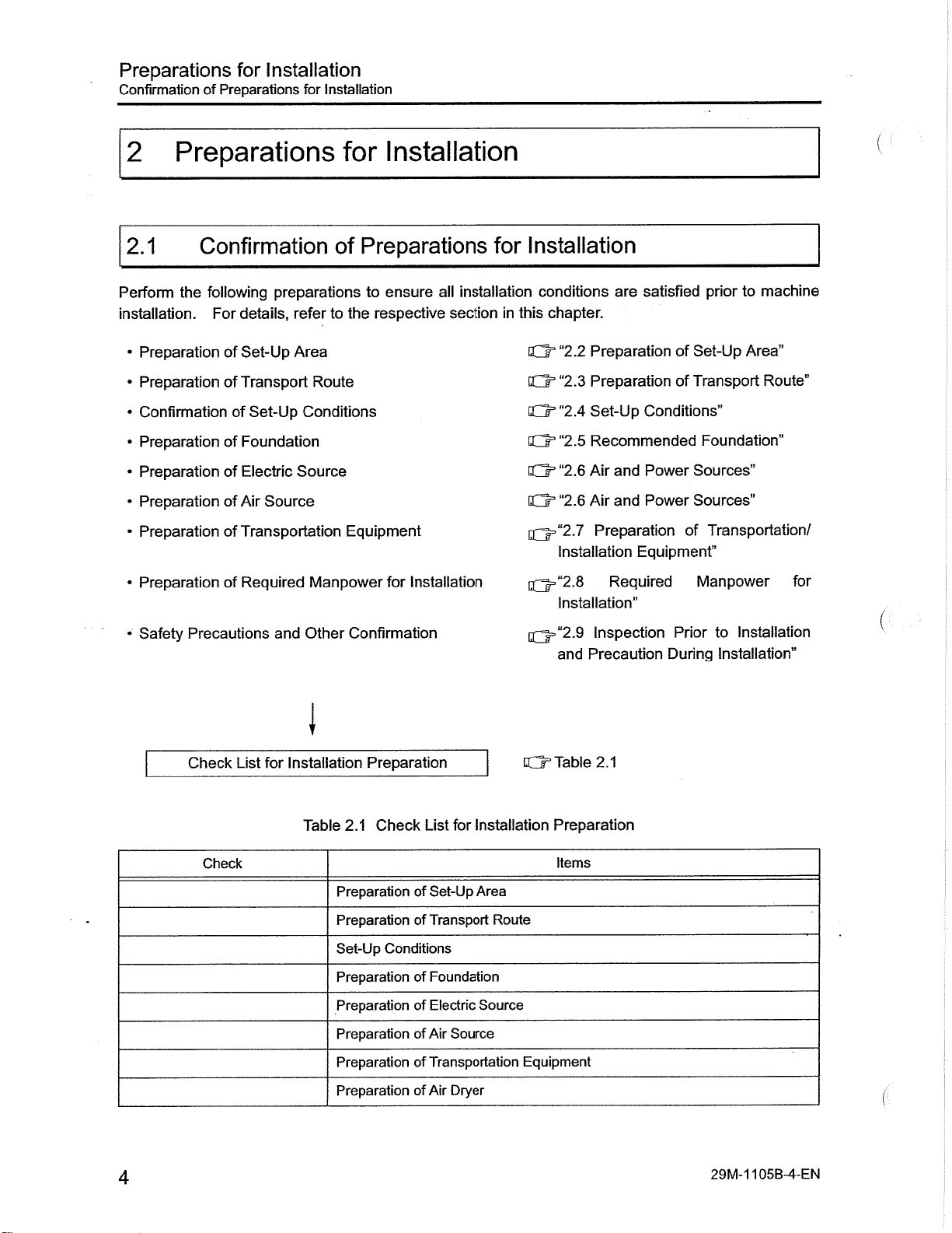
Perform
installation.
of
Preparations
Confirmation
following
the
For
for
Installation
preparations
details,
for
refer
Installation
Installation
for
Preparations
of
ensure
to
respective
the
to
all
installation
section
Installation
for
conditions
this
chapter.
in
are
satisfied
prior
machine
to
•
Preparation
PreparationofTransport
•
Confirmation
•
Preparation
•
•
Preparation
•
Preparation
•
Preparation
•
Preparation
Safety
•
of
Set-Up
of
Set-Up
Foundation
of
Electric
of
of
Air
Transportation
of
Required
of
Precautions
Check
List
Source
for
Area
Route
Conditions
Source
Manpower
and
Other
I
Installation
Equipment
Installation
for
Confirmation
Preparation
“2.2
0=
Q=“2.3
IQ3
“2.4
“2.5
Q=
“2.6
Q=
“2.6
cCt3
[Q=“2.7
Installation
[Q=“2.8
Installation”
y-“2.9
I,r
and
Table
er
Preparation
Preparation
Set-Up
Recommended
and
Air
and
Air
Preparation
Required
Inspection
Precaution
2.1
of
of
Conditions”
Power
Power
Equipment”
Prior
During
Set-Up
Transport
Area"
Foundation”
Sources”
Sources”
Transportation/
of
Manpower
Installation
to
Installation”
Route”
for
Installation
for
List
Set-Up
of
Transport
of
Conditions
Foundation
of
Electric
of
Air
of
Transportation
of
of
Air
Area
Route
Source
Source
Dryer
Check
Table
Check
2.1
Preparation
Preparation
Set-Up
Preparation
Preparation
Preparation
Preparation
Preparation
4
Preparation
Items
Equipment
29M-1
05B-4-EN
1
Page 10

Preparations
Preparation
Installation
for
Set-Up
of
Area
2.2
Refer
specifications
Note
•
•
•
Preparation
the
to
following:
the
When
The
maintenance
maintenance
The
specifications:
Tool
a81
Tool
a81
Tool
a81
Tool
a81
Spec.
Tool
a82
Tool
a82
Tool
a82
figures
to
confirm
lifting
the
Magazine
Magazine
Magazine
Magazine
Magazine
Magazine
Magazine
Set-Up
of
section
this
in
requirements
space
machine
area
body
the
is
varies
area
A40/Left-Discharge
A60/Left-Discharge
A97/A1
A40/Left-Discharge
A60/Left-Discharge
A97/A1
37/Left-Discharge
A186
37/Left-Discharge
Area
show
that
using
a
maintenance
depending
Above/Rear-Discharge
or
general
the
prepare
and
crane,
space
Conveyor
Conveyor
Conveyor
Conveyor
Conveyor
Conveyor
the
on
view
the
lifting
total
required
type
the
Spec.
Spec.
Spec.
Conveyor
Spec.
Spec.
Spec.
floor
and
required
height
after
of
for
plan
set-up
installation.
tool
area.
required
magazine
Figure
G3
Figure
0=
Figure
0=
Figure
0=
Figure
Q=
Figure
0=
Figure
Q=
respective
is
4627mm.
and
and
2.1
2.3
and
and
2.5
and
2.7
and
2.9
2.11
2.13
machine
conveyor
2.2
2.4
2.6
2.8
2.1
and
2.12
2.14
and
I
§
1
ro
w
a
c
.2
2
CO
0
a.
CM
2
Tool
a82
Spec.
NOTE:
general
A
specifications
view
Magazine
and
not
are
A186
floor
plan
showninthis
Above/Rear-Discharge
or
20000min'1
the
for
section.
spindle
Conveyor
specifications
EQ=
and
Figure
double
2.15
lift-up
2.16
and
conveyor
29M-1
05B-5-EN
1
5
Page 11

Preparations
Set-Up
Preparation
of
Installation
for
Area
2.2.1
a81
Preparation
General
tn
ON
CM
m
View:
109
Tool
I
Set-Up
for
Magazine
Heightÿ-
'<3#$
3443
i
l£J
Area:
Left-Discharge
A40,
n
In
IZJ
tZJ
5475
a81
6652
Conveyor
1550
482
Jd
n
(1068)
in
CM
ON
CM
o
m
CM
m
m
r\j
CO
m
£
M-
m
CM
vO
CM
o
P
o
973
1080
2220
3693
g/
1140
mjy-1
500
in
CM
r".
(495)
o
m
in
CM
ON
CM
m
m
CM
4188
View
of
Lift-Up
(Tool
Figure
Magazine
2.1
A40
Front
and
and
Left
Side
Discharge
Machine:
6
a81
Conveyor
Spec.)
29M-1105B-6-EN
Page 12

Preparations
Preparation
Installation
for
Set-Up
of
Area
a81
APC
o\
trt
Floor
Collector
Mist
(Option)
Operation
Panel
o
m
o\
m
S
CO
S
o
Plan:
Tool
Tool
\
Magazine
Magazine
(Ring)
A40
2142
IF
A40,
Hydraulic
/
%-HO
Left-Discharge
Spindle
Temperature
Unit
5932
1857
m
Conveyor
Cooling
Controller
1933
Iff
B
Oil
Lift-Up
9
Conveyor
Chip
Outlet
o_
2120
Air
(Option)
/
"c
|S
C
o
Dryer
o
N
tn
CM
NO
m
in
o
K
I
|
§
S
w
a
w
a
E
0
CL
CM
o
NO
o
(Maintenance
Areaÿ)
Operationÿ
Main
(Tool
109
809
2300
Panel
Figure
Magazine
2.2
7
Machine
Floor
A40
and
R,
W/
Or,
3443
Controller
Plan
Left
\
Step
5475
8052
Additional
Torque
View
(Top
Discharge
A
&
1550
5752
Transformer
Controller
Spindle
Machine):
of
Lift-Up
Conveyor
71
482
(Option)
Head
a81
600
(1068)1
High-
for
(Option)
Spec.)
5
3
700
Cutting
Temperature
in
m
in
/
NO
inf
ON
ON
Fluid
Controller
(Option)
29M-1
05B-7-EN
1
7
Page 13
Preparations
Preparation
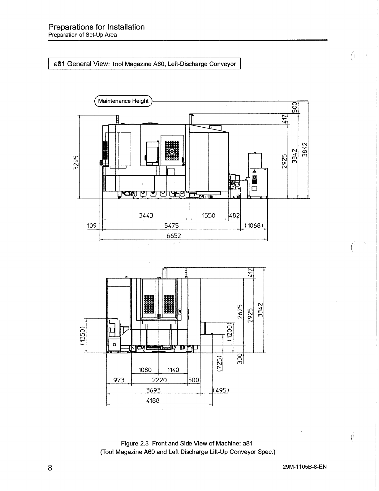
General
a81
of
Set-Up
for
Installation
Area
View:
Tool
Magazine
Left-Discharge
A60,
Conveyor
in
c?\
Osl
m
109
1
n
Heightÿ-
gj
0
3443
I
gj
In
I3i
5475
6652
is!
J«!
W
1550
ath
482
A
1
(1068)
M-
in
CM
CK
CM
o
in
CM
m
m
m
CM
00
in
CM
o\
CM
a81
CM
m
m
Spec.)
29M-1105B-8-EN
in
CM
NO
CM
m
CN
(495)
of
Machine:
Lift-Up
o
CM
o
m
Conveyor
s
in
H-P
o
973
(Tool
IT
mssssmamu
Figure
Magazine
1080
3693
4188
2.3
A60
2220
Front
and
1140
and
Left
500
View
Side
Discharge
8
Page 14

Preparations
Preparation
Installation
for
Set-Up
of
Area
APC
m
o\
in
a81
Floor
Collector
Mist
(Option)
Operation
Panel
o
s
00
§
m
o\
£
m
o
Plan:
Tool
\
Magazine
Tool
Magazine
1379
\
A60
/
*
A60,
Spindle
(Ring)
2620
Hydraulic
5
3
Left-Discharge
Temperature
Cooling
5932
Oil
Controller
Unit
\
i
s
Conveyor
1933
Lift-Up
Conveyor
Chip
Outlet
O
2120
Dryer
Air
(Option)
(2
I
§
is
3
a
B
0.
<N
eg
w
2
CO
£
>o
m
in
o
o
c
03
O
m
04
o\
m
o
in
o
in
in
o
%
&
1550
5752,
Controller
Spindle
&
(Option)
Head
482
600
(1068
for
High-
(Option)
700
Controller
Area
109
809
J
Main
2300
Operation
Panel
m
Or
Step
3443
5475
8052
Machine
Additional
Torque
Controller
Transformer
m
in
/
„/
'O
in
O'
ON
vt
Cutting
Temperature
Fluid
(Option)
29M-1
105B-9-EN
(Tool
Figure
Magazine
2.4
A60
Floor
and
Plan
Left
View
(Top
Discharge
Machine):
of
Lift-Up
a81
Conveyor
Spec.)
9
Page 15

Preparations
Set-Up
Preparation
of
Installation
for
Area
a81
General
View:
in
o\
(SI
m
109
Tool
Magazine
Heightÿ-
n
A97/A137,
izjgj
ci
3443
Left-Discharge
Q
5475
6652
1550
Conveyor
i
482
(1068?
I
o
in
£
Csl
CvJ
oo
in
(NJ
c?\
A
m
m
m
10
o
JR
(Tool
s
IP
Magazine
m
IB
1542
Figure
2.5
A97A/A137
Front
and
1080
4262
4732
and
2220
Side
Left
I
u
1140
View
Discharge
2E
500
Machine
of
Lift-Up
O
£
in
CN
r-.
(470)
Conveyor
in
[SI
o
CM
o
m
(Nj
m
m
CN
m
o
CNI
Spec.)
29M-1105B-1
('
0-EN
Page 16

Preparations
Preparation
Installation
for
Set-Up
of
Area
a81
Mist
APC
CM
vO
m
in
Plan:
Floor
Tool
Magazine
Collector
(Option)
Operation
Panel
o
o\
CO
CM
NO
§
£
o
o
T—
Tool
A97/A137
\
Magazine
1983
A97/A137,
(Matrix)
5034
O
:Ef
Left-Discharge
Spindle
Upper:
Hydraulic
Lower:
2351
5
;
V/
IB
Cooling
700
ZZ3I
Q
Conveyor
Oil
Unit
Lift-Up
Chip
r
Temperature
3018
Conveyor
Outlet
Air
(Option)
_-4
-"1
Controller
Dryer
|2
m
oo
T~
in
CM
oo
NO
co
in
in
I
§
2
&
a
a
5
to
£
CL
CM
o
o
rÿ
3
Maintenance
109
809
Area)
(Tool
2300
Operation
Main
Panel
Figure
Magazine
to,
Q:
7
Floor
2.6
A97/A137
3443
Machine
Plan
and
Step
5475
8052
Left
Controller
Transformer
Additional
Torque
(Top
View
Discharge
A
1550
5752
Controller
Spindle
Machine):
of
&
(Option)
Head
Lift-up
482
600
(1068)1
High-
for
(Option)
a81
Conveyor
700
Controller
Spec.)
in
m
in
/
in
vo
o\
05
Cutting
Temperature
Fluid
(Option)
29M-1
105B-1
1-EN
11
Page 17
Preparations
Preparation
of
Set-Up
for
Installation
Area
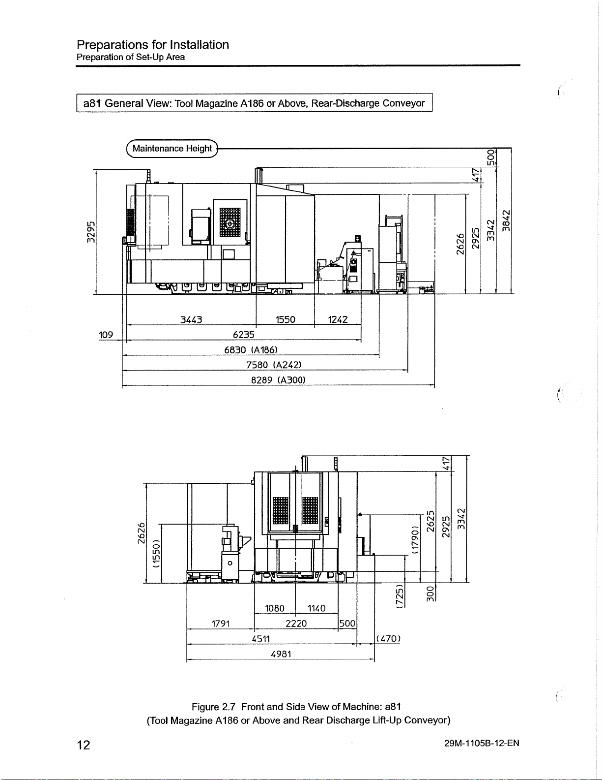
a8t
in
o\
CN
m
General
109
View:
1
Magazine
Tool
Heightÿ
gfe
igj
3443
6235
6830
A186
(A186)
7580
8289
Above,
or
1550
(A242)
(A300)
Rear-Discharge
)ÿ
1242
Conveyor
CM
o
CN
o
in
CM
CM
CO
in
CN
vO
Ov
CN
m
m
m
(
12
o
CN
vO
CM
LH
in
(Tool
Figure
Magazine
B»
o
1791
Front
2.7
A186
or
II
I
1080
4511
and
Above
4981
and
2220
Side
1140
View
Rear
i
1
500
Machine:
of
Discharge
(470)
a81
Lift-Up
in
CM
Conveyor)
in
CM
CN
o
m
CN
in
vO
CN
o\
CN
29M-1105B-1
m
m
2-EN
Page 18
Preparations
Preparation
Installation
for
Set-Up
of
Area
Tool
Mist
APC
00
'O
o
es
o
'O
m
5
a81
r*-.
Floor
Magazine
Collector
(Option'
Operation
Panel
o
5
5
Nj-
§
o
5=
O
Cÿ.
Plan:
Tool
A1
86/A242/A300
(Matrix)
1563
x
Magazine
1253
1165
\
w
3
(£/
A186
Lift-Up
1346
346
m
/I
Step
Above,
or
Conveyor
CO
CO
/
Rear-Discharge
\4782
Air
(Option)
~
T
T
B5
{£
I
A
S’
Upper:
Dryer
$
Spindle
5527
\
Cooling
750
a>
o
f
O
\
\
Temperature
Oil
709
700
7
Lower:
/
-IS
fi
Controlle
Hydraulic
o
fv.
CN
>0
in
o
£
CN
CN
CO
/
/
§
0O
>o
>o
Eri
3
Un
(N
tZ
I
1
§
B
£
C
2
2
a.
CNJ
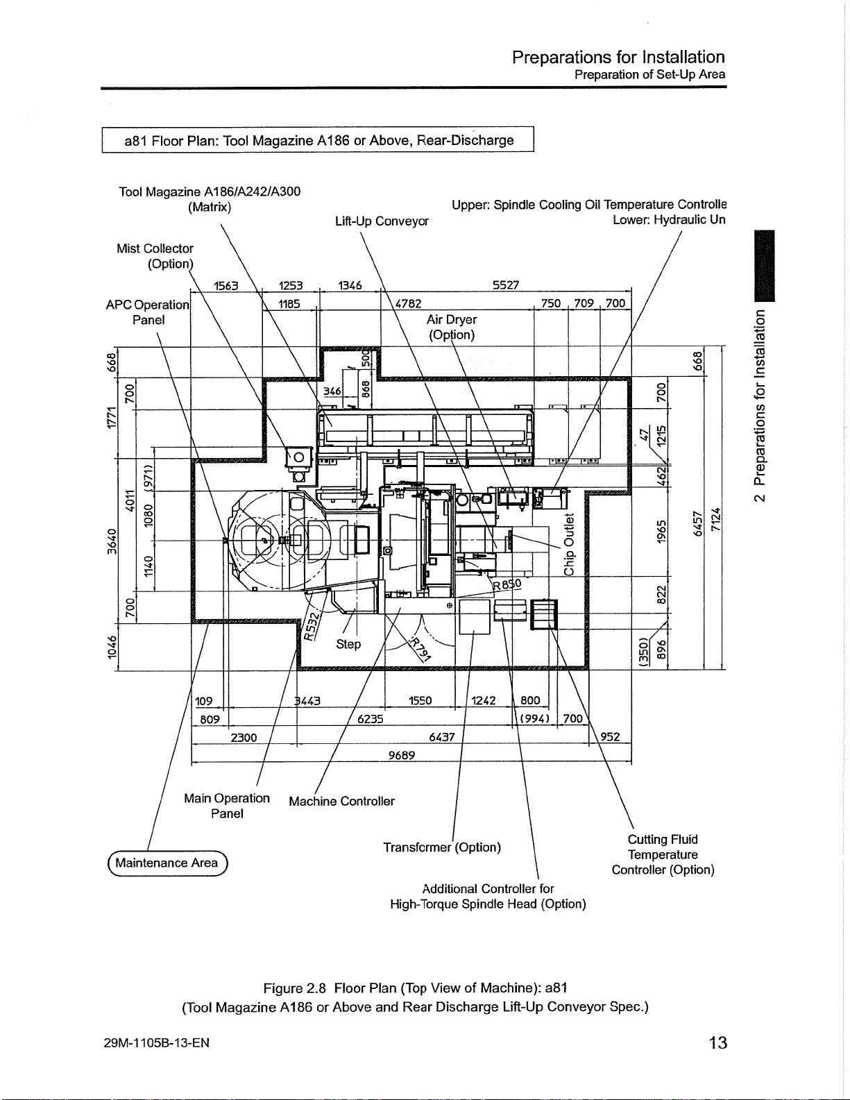
29M-1
109
Main
AreaJ)
(Tool
105B-13-EN
809
2300
Operation
Panel
Magazine
Machine
Figure
A186
3443
2.8
7
or
7
Floor
Above
6235
/
Controller
Transformer
Plan
and
1550
6437
9689
Additional
High-Torque
(Top
View
Discharge
Rear
1242
(Option)
Controller
Spindle
Machine):
of
800
(994)
Head
Lift-Up
700
for
(Option)
a81
Conveyor
952
Cutting
Temperature
Controller
Spec.)
Fluid
(Option)
13
Page 19

Preparations
Set-Up
Preparation
2.2.2
of
Preparation
Installation
for
Area
.
for
Set-Up
Area:
a82
a82
S
co
m
m
General
View:
Tool
3130
Magazine
HeightJ-
6405
A40,
Left-Discharge
~ar\
7230
i
o
eSiP
2183
Conveyor
_
Li
1092
lidri
(825)
o
in
rn
NT
oo
GO
OS
GO
m
GO
m
i
14
in
CM
01
CM
(Tool
§
SB
Figure
Magazine
F
973
3HE=
Front
2.9
A40
1180
3891
and
2360
4344
and
Left
!msi
1180
View
Side
Discharge
558
Machine:
of
Lift-Up
in
CM
CM
453
Conveyor
o
CM
*-
a82
3
CM
in
CM
3
CM
o
m
Spec.)
29M-1
05B-1
1
4-EN
Page 20

Preparations
Preparation
Installation
for
Set-Up
of
Area
a82
Floor
Mist
Collector
(Option)
o
fn
D\
§
m
CNJ
1
GO
in
m
APC
Operation
Panel
Plan:
Tool
Tool
Magazine
A40
550
24Q
///W/>
77/
'/////A
\
®
O
I
u
s
J0(,0
lili
I
r
/
700
j
///////y/////////////)//////////j
Magazine
(Ring)
863
////////////
a
a
635
635
2480
Left-Discharge
A40,
Operation
185;
v&A£ÿ////r//////////////,
-VV'c
1220
STROKE)
Z
Tool
--
-Sies
6405
Magazine
Panel
Hydraulic
454.6
'///A/y
200
/
GAUGE
2833
6605
Conveyor
750
/
////////A
si
W
Wllf
1
1
Unit
'///////////As
o
co
Nj
_[
iStf
Controller
Coolant
o
o
o
o
Oil
Tank
Air
(Option)
2
I
Dryer
CN|
m
P
g
•-a-
I
Outlet
15(
Cooling
,390,
:
Spindle
Temperature
Conveyor
Lift-Up
W777777Z77777777777A7777777777rf
Chip
m
ml
A
m
a
H
!n
I
s
t>.
§
>50
/
1092
m
:
||
IPO
ooi
800
1
650
-
„
in
NO
B
1500
cr\
m
-
I
y,
m
s
|
\
2
1
vx
A
700
I
§
’is
=3
to
_c
£
w
~
CO
to
CD
a.
CM
Maintenance
(
29M-1
105B-15-EN
Collector
Mist
(Option):
or
MMC
Area)
(Tool
with
PM
Main
Figure
Magazine
Operation
Panel
2.10
A40
Floor
and
Machine
Plan
Left
Controller
Transformer
View
(Top
Discharge
High-Torque
Machine):
of
Lift-Up
(Option)
Additional
Conveyor
Spindle
a82
Controller
Head
Spec.)
Cutting
Temperature
Controller
for
(Option)
Fluid
(Option)
15
Page 21
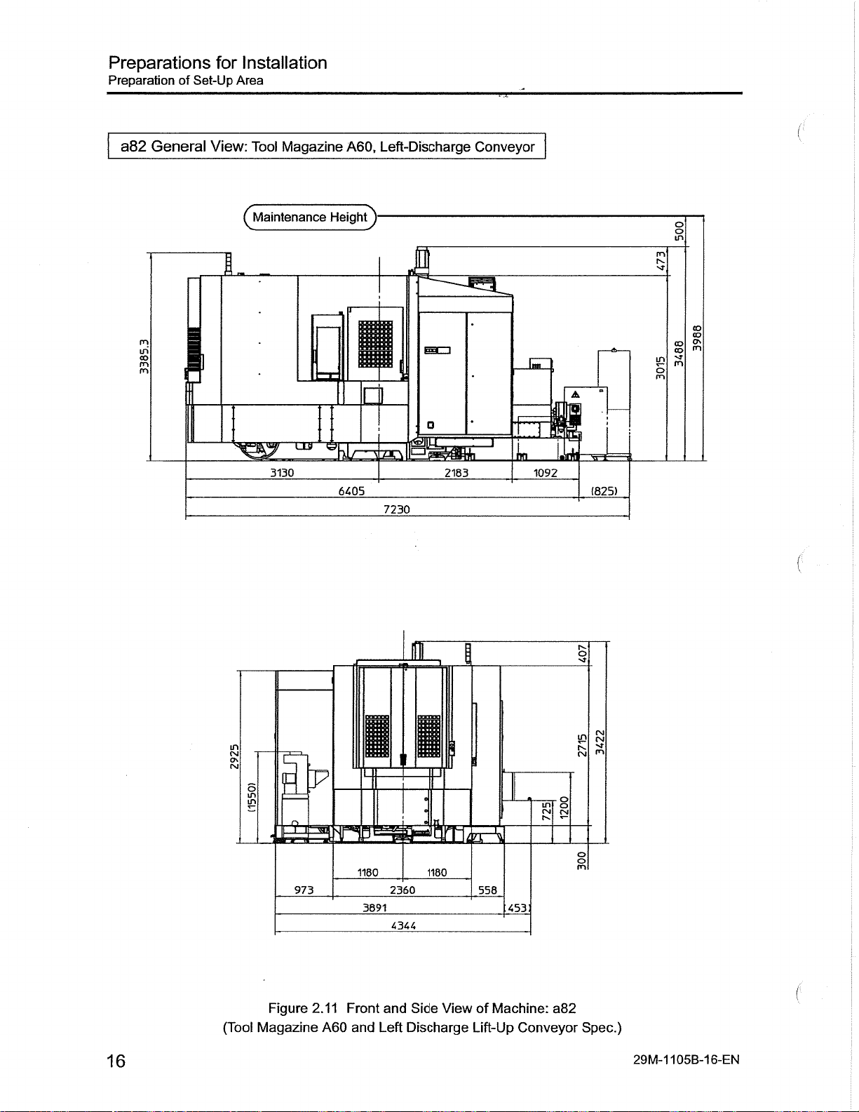
Preparations
Preparation
General
a82
Set-Up
of
Installation
for
Area
View:
Tool
Magazine
Left-Discharge
A60,
Conveyor
5
m
m
CO
(ÿMaintenance
3130
Heightÿ-
1
19
33
6405
7230
1
2183
L
1092
A
LLI
1825)
o
in
rn
sj-
co
CO
ON
co
m
co
rn
§
16
in
(SI
ON
(SI
(Tool
ELF
a
£
Figure
Magazine
973
2.11
A60
I
Front
1180
3891
and
2360
4344
and
Left
KH
1180
Side
View
Discharge
558
of
Machine:
Lift-Up
O
in
o
(SJ
CM
a82
Conveyor
3
CM
LT)
CM
rn
(SI
o
m
Spec.)
29M-1
105B-16-EN
Page 22

Preparations
Preparation
Installation
for
of
Set-Up
Area
a82
Mist
Collector
(Option)
o
fs.
m
s
s
m
CM
I
co
in
in
APC
Operation
Panel
Floor
r
I
f
H
I
\
Z
v////////
Plan:
Z///X,
ill
'00
24Q
s'
Tool
Tool
A60
550
///
'///////
vO
u
\
v//////////////r//////////y
Magazine
Magazine
(Ring)
1(
ZV777X777777777Zÿ7777777777777777y77
\
Left-Discharge
A60,
Hydraulic
2620
\
Spindle
Temperature
Unit
,454.6
V///A
\
13
530
635
IP
a
635
2480
1220
///////
5TR|
l
6405
_
200
GAUGE
8605
Conveyor
Cooling
Controller
\750
Y777A77777.
W
TOIE"
2833
Oil
,3Ll
/
Lift-Up
V777777777}
I'M
100
V/A/S/S/////,
Coolant
Conveyor
V7777777777777777T777777777/7?t
Chip
Outlet/
1507,390,
1
Tank
Air
(Option)
I
2
Dryer
CM
m
P
I
?0Q
1
I
650
.1
\
s
|
I
3
sj
in
I
Ovi
in
I
CM
£
rs
1
1
o
1092
700
'//////////
800
700
1500
I
1
8
’is
v>
c
£
W
S
2
TO
a>
Q.
CM
29M-1
Areaÿ
Mist
105B-17-EN
Collector
MMC
with
(Tool
Main
Operation
Panel
(Option):
or
PM
Figure
Magazine
2.12
A60
Step
Floor
and
Plan
Left
Machine
Transformer
(Top
View
Discharge
Controller
(Option)
High-Torque
Machine):
of
Lift-Up
Additional
Spindle
a82
Conveyor
Controller
Head
Spec.)
Cutting
Temperature
Controller
for
(Option)
Fluid
(Option)
17
Page 23

Preparations
Preparation
Set-Up
of
Installation
for
Area
a82
General
m
in
co
m
m
View:
Tool
Magazine
(ÿMaintenance
LJJ)
3130
A97/A1
37,
Heightÿ-
d
<S(
6405
7230
Left-Discharge
II
Lf
2183
Conveyor
L
1092
o
in
m
oo
co
ON
CO
m
co
in
rn
m
A
(825)
18
(Tool
g
8
e
Figure
Magazine
1540
2.13
Front
A97/A137
1180 1180
2360
4458
4911
and
Side
Discharge
Left
and
558
453:
ViewofMachine:
Lift-Up
Conveyor
II
a82
I
Sg
fvj
1
Spec.)
29M-1
05B-1
1
8-EN
Page 24

Preparations
Preparation
Installation
for
Set-Up
of
Area
a82
Floor
Mist
I
c\i
&
I
5
Plan:
Magazine
Tool
Operation
Collector
(Option)
§
§
Tool
Tool
Panel
m
i
K
i
Magazine
Loading
Station
844
5
§
in
2
S
19
p
in
550
\
\
Tf
5
635
A97/A137,
\100
O
a
U
635
Left-Discharge
2351
\
3!
1020
KE)
STH
a
Conveyor
Tool
Upper:
Lower:
480
Magazine
Spindle
Hydraulic
Lift-Up
1915
A97/A137
Cooling
Unit
Conveyor
(Matrix)
Temperature
Oil
Chip
Outlet
Coolant
/
/
Controller
Tank
Dryer
Air
(Option)
I
§
1
2
I
3
K
1170
rm
540
g
S
L
|
1
1
I
I
s
IL
2
\
TZ
i*
m
S3
§
I
t
y
y
200
0AU0I
w
SL
/
ioo
650
100,
1
W
a
w
a
E
0
CL
CM
Operation
29M-1
/
APC
Areaÿ)
(Tool
105B-19-EN
/
Mist
700
Collector
MMC
with
Machine
Magazine
1133,
Main
(Option
or
Figure
550
2480
Operation
Panel
):
PM
Controller
Floor
2.14
A91/A137
797
Step
Plan
and
'1100
2833
6405
Machine
Controller
(Top
Discharge
Left
1733
/8605
Transformer
Machine):
of
View
Lift-Up
1092
(Option)
Additional
Torque
Spindle
Conveyor
800
Controller
Head
a82
1500
Controller
for
(Option)
Spec.)
Cutting
Temperature
High-
Fluid
(Option)
19
Page 25

Preparations
Set-Up
Preparation
of
Installation
for
Area
a82
s
s
General
View:
Tool
3130
Magazine
3763
i
Above,
or
A186
Heightÿ
&
2183
8545
Rear-Discharge
i
1550
]ÿ,
1736
Conveyor
:
3232
nn
:
: :
A
(1496)
1
5
I
20
(Tool
S
£
Magazine
1790
Figure
A1
IIP
o
2.15
or
86
4708
Front
Above
1180
and
and
2360
Side
Rear
I
1180
Machine:
of
View
Discharge
558
Lift-Up
§
s
§
£
a82
Conveyor
CM
CM
Spec.)
29M-1
105B-20-EN
Page 26

Preparations
Preparation
Installation
for
Set-Up
of
Area
a82
Mist
o
£
I
s
I
§
S
APC
Operation
Panel
Floor
Collector
(Option)
li
7
/
700
Plan:
1609
w
Ss
/
640
Tool
700
s
5
635/
>480
Magazine
Magazine
Tool
1533
550
100/
o
m
A
CF
1020
635
A186
(Matrix)
1391
500,391,500
F
m
200
913B
Above,
or
A186/A242/A300
Rear-Discharge
6291
I
5532
4782
\
s
T
GAUGE
&
LINE
2B33
9900
$
Upper:
6241
oT
>o
'650
100
Spindle
Coolant
5367
Irr,
~
5B5
Cooling
i
660/242
N
Ml
T
>9(
7001
Tank
80u
-lx
Temperature
Oil
Dryer
Air
(Option)
74B,
;
\\
\
\
'00
Lower:
700
655
V
\
\
762
Controller
Hydraulic
I
gv
s
I
jy?
§
I
s
3l§
Wi
6
Outlet
Chip
Unit
S
I
I
I
11
8
is
a
c
-2
E
CL
CM
Q.
£
29M-1
Areaÿ)
MistCollector(Option):
(Tool
105B-21-EN
/
Main
or
MMC
with
Figure
MagazineA186
Step
Operation
PM
2.1
or
Panel
Machine
Floor
6
Above
Controller
(Top
Plan
Left
and
Transformer
Additional
High-Torque
View
of
Discharge
(Option)
Controller
Spindle
(Option)
Machine):
Lift-Up
for
Head
a82
Conveyor
Cutting
Temperature
Controller
Lift-Up
Conveyor
Spec.)
Fluid
(Option)
21
Page 27

Preparations
Preparation
Transport
of
for
Installation
Route
'*
*
2.3
Prepare
Magazine
Tool
The
tool
a81
Main
Magazine
(Tool
a81
Main
(Tool
Magazine
a82
Main
Magazine
Magazine
Tool
The
tool
Table
a81
Main
a82
Main
Tool
Magazine
Magazine
Tool
Tool
Magazine
Magazine
Tool
Tool
Magazine
PreparationofTransport
machine
the
magazine
Table
2.2
Item
Machine
Machine
Machine
A40/A60)
magazine
2.3
Item
Machine
Machine
A40/A60
is
Machine
A40)
A60)
(Tool
A97
is
Machine
A97
A137
A186
A242
A300
transport
assembled
and
not
Size
Above
installed
Size
Shipment
route,
onto
Shipment
3342mm
(10=
3342mm
(Gh
3422mm
(Gh
onto
3342mm
(GhNOTEI)
3422mm
(Oh
3090mm
3090mm
2626mm
2626mm
2626mm
referring
main
the
Dimensions
Height
NOTE
1)
NOTE
1)
NOTE
1)
the
main
Dimensions
Height
NOTE
1)
Route
the
machine
to
machine
Height
Lifting
(Ch
(Q=NOTE
(O’
machine
(a81/a82
Height
Lifting
(GhNOTE
(GhNOTEI)
shipment
size
priortoshipment.
With
With
with
1)
1)
1)
shipment.
to
Tool
with
1)
(a81/a82
Equipment
4727mm
NOTE
4727mm
4807mm
NOTE
prior
Equipment
4727mm
4807mm
4080mm
4080mm
5310mm
5310mm
5310mm
Magazine
Tool
Width
3032mm
3007mm
3255mm
Magazine
Width
3020mm
3255mm
1835mm
1835mm
1096mm
1096mm
1096mm
dimensions.
A40/A60)
or
A97
Depth
4993mm
4993mm
5356mm
Above)
Depth
4993mm
5356mm
2462mm
2462mm
4782mm
5532mm
6241mm
(
(
Lifting
•
Tool
•
Spindle
0=
Spindle
•
•
Coolant
NOTES:
For
1
above
When
2
adequate
22
of
Units
Figure
the
Magazine
Cooling
4.3
Oil
Temperature
Tank
high-torque
lifting
lifting
plus
the
height
A97
Gh
66mm.
main
space
and
Above
Oil
Temperature
Controller
Figure
spindle
machine
is
500mm
4.4
(Matrix)
Controller
(For
20000min*1
and
using
the
plus
Figure
Ch
20000min"1
spindle
crane,
a
height
the
with
2.18
other
(For
spindle
specifications,
necessary
lifting
the
20000min"1
than
spec.)
total
Gh
the
height
equipment.
Figure
machine
required
spindle
4.3
height
29M-1
spec.)
is
the
provide
to
105B-22-EN
Page 28

Preparations
Preparation
Installation
for
Transport
of
Route
|
a81/a82
|
a81
A
a
rÿu
i
i
1
a
;
I
j
1
«
£.
&
c
a
2
TO
£
CL
C\J
1ÿ1
TBj
°ÿ3Z>
Q
n
Width
Height
II
jl
jj
A
°
n
Q=
Using
ox
—
qpHPP
o
BB
Q
Table
Crane
JTQ
2.2,
a
§
n
Table
for
Lifting)-
2.3
Height
Using
Crane
for
O
in
§
!M
CM
m
m
(Required
n
II
II
jj
u
I
*
TBj
4
o
n
Width
o
n
10=
o>
—
qmpo
Q
a
Table
JTo
R
2.2,
R
n
Table
Lifting)-
2.3
o
in
CO
CM
CM
rn
in
C7\
CM
8
Figure
29M-1
2.17
05B-23-EN
1
Main
Machine
Size
When
Being
Transported
(With
4-Point
Lifting
Equipment:
a81/a82)
23
Page 29

Preparations
Transport
Preparation
of
Installation
for
Route
l
o
3534
Tool
Sfi
Magazine
1835
A97/A1
O
3
as
37
I
g
8
(Matrix)
(
te1
24
Tool
-=S=r
Depth
Magazine
<r
|
*
2.3
Table
O’
A186/A242/A300
Figure
2.18
LI
j
Lifting
a
D
(Matrix)
Tool
of
s
SQ
Magazines
Sub-Arm
(Matrix)
A1
86
(Tool
or
Above)
Magazine
105B-24-EN
29M-1
(
Page 30

Preparations
Installation
for
Set-Up
Conditions
2.4
-
Confirm
Ambient
Relative
Temperature
Well-illuminated
Free
Dust-free
Available
Available
Adequate
Required
Set-Up
following
the
Temperature
Humidity
from
direct
space
space
space
electrical
set-up
Fluctuation
sunlight
storing
for
maintenance
for
around
power
Conditionsÿ
-
to
than
work
to
Table
Location
70%
1°C/30
open
and
(Optimum
(No
finished
doors
location
Set-Up
10°Cto40°C
35%
Less
materials,
raw
machine
sources
.
environmental
Set-Up
2.4
Environmental
and
Temp:
Condensation)
minutes
(Range
workpiece
completely
conditions
Conditions
Conditions
20°C
which
and
±
1
tools
°C)
does
prior
not
machine
to
influence
set-up.
machining.)
I
1
§
c
£
w
a
S
to
£
Q.
eg
level
A
foundation
Appropriate
strong
distance
from
enough
factory
to
support
air
ducting/inlets
the
weight
(Air
of
the
Flow)
machine
29M-1
105B-25-EN
25
Page 31

Preparations
Recommended
Foundation
for
Installation
2.5
Construct
Symbol*
a
b
c
d
Indicates
*
Recommended
appropriate
an
Ground
Foundation
Main
Machine
Jet
Resistance
Machine
Fixing
Anchor
Insulated
Jet
Anchor
Foundation
Recommended
Recommended
Leveling
Concrete
(Weight
-Figure
Concrete
(Weight
-Figure
symbols
Concrete
based
2.21
based
2.24
used
foundation,
Thickness
Support
Tool
for
Main
Foundation
for
Iron
Weight
Magazine
Tool
Bar
Concrete
Rubble
Thickness
for
on
the
0=NOTE
Weight
on
G1
in
for
the
NOTE1)
Figure
machine
from
Tool
dimensions
Tool
Foundation
referring
by
2.5
Table
Item
Point
Surrounding
A97
Magazine
1)
Magazine
dimensions
Figure
2.19
-
to
Table
Recommended
Vibration
and
Above
(a81)
Figure
(a82)
Figure
2.24.
2.19
2.22
in
in
and
2.5
Foundation
ton/m2
8
500mm
points
3
points
3
points
crushed
points
NOTE
(CCS3
Magazine
Magazine
Magazine
Magazine
Magazine
Magazine
Magazine
Magazine
Magazine
(M16:
(M16:
<|>19mm,
standard
or
6
Small
4
Vertical:
(G=
FC180
Medium
50mm
Tool
Tool
Tool
Tool
Tool
Tool
Tool
Tool
Tool
Figure
above
or
Jet
stone
Jet
)
1
Large
NOTE
A97/A1
A186/A242:
A40/A60:
A97/A1
A186:
A242:
A300:
2.19
Description
Anchor)
Anchor)
Horizontal:
and
above
Size
Crushed
1)
A40/A60:
37:
A300:
22.7ton
37:
21.4ton
22.1
22.8ton
Figure
~
(Q=
16,3ton
18ton
21ton
18.5ton
18.5ton
ton
2.24.
<|>22mm
NOTE1
Stones
)
NOTES:
These
1
is
It
2
when
Tool
3
Dimensions
installation
values.
As
4
the
professional
according
26
values
necessary
installing
Installation”
foundation.
machine
this
surrounding
to
reference/recommended
are
to
use
the
machine
options
the
indicatedinthis
operates
area
engineer
civil
the
actual
(matrix
foundation
foundation
The
high-speeds,
at
depending
determine
to
ground
fixing
magazine,
upon
conditions
values.
tools
pallet
drawing
drawings
vibration
the
the
final
and
possible
to
order
in
magazine
minimum
are
following
on
generated
foundation
foundation
influence
secure
or
the
MMC).
requirements
pages
by
machine
ground
and
dimension
the
on
machine
main
“3.4
Q=
Machine
given
only
show
operations
conditions.
requirements
surrounding
29M-1105B-26-EN
the
floor
to
Fixing
solid
good
for
recommended
may
affect
Consult
they
as
a
vary
area.
/
Page 32

Preparations
Recommended
Installation
for
Foundation
a81:
Magazine
Tool
g
tL
Is
§
o
CM
§
Leveling
X
I
A40/A60
A
Concrete
ZHZ
\
/
Z
/
a
424
100
Main
150
Left-Discharge
and
5
I
s
\
1520
Machine
u
mrr°
/
Rubble
200
200X15-3000
3300
Main
b
E
4-r
2480
3300
3500
Foundation
b
l/\
B
Conveyor
Machine
b
V
b
960
b
I
TfTTT
C
-eÿ|
Foundation
c
396
100
Reinforced
I
\
C
150
a;
Main
b:
Jet
Isolated
c:
u
w
\o
&
:
in
co
T~
Machine
Anchor
Concrete
§
s
m
m
o
CM
O
c$
>o
£
s
-o
S
rn
rn
in
o
o
V
Support
Machine
for
Foundation
Point
I
1
.2
to
to
k.
£
.2
CL
CM
c:
w
c
ro
TO
Q.
(D
Angle
Detailed
Figure
29M-1
Steel
65
15
50.
in
o
in
tv.
\0
View
of
A
/
a81
2.19
105B-27-EN
Plate
sr
Detailed
of
Foundation
Hex
C7v
in
rv*
CM
O*
o-
Section
Bolt
026
View
B
Drawing
/
485
O
022
(Tool
o
mi
'P
DRILL
Magazine
Anchor
Bolt
o
S
A40/A60
°
9
tri
'
and
Hex
in
cK
rsi
Detailed
of
Section
Left
Bolt
A
030
View
C
Discharge
485
022
/
Anchor
-o
DRILL
Conveyor
Bolt
Spec.)
27
Page 33

Preparations
Recommended
Foundation
Installation
for
Tool
Main
Tool
a81:
Magazine
Machine
Magazine
FoundationN
Foundation
C
o
$<
O
(N
LA
lf§
VO
5?
o
CM
s
a
A97/A137
439
100
i
424
100
and
>
-
\
XQEffi
1520
Left-Discharge
2500
2300
n
n
B
b
-
960
2460
3300
3500
V
b
561
100
b
396
Conveyor
/I
D
3
a
100
§r
o
vO
£
ov
5
in
CO
-O
Main
a:
b:
Jet
Isolated
c:
d:
Jet
o
S
in
in
m
m
o
Machine
Anchor
Anchor
30Q
250
m
£
o
o
o
"S
O
£
.£
<D
cc
Support
Machine
for
Foundation
for
Tool
150
50
Leveling
Concrete
Rubble
m
WB
|—
Point
Magazine
(
Angle
Detailed
Figure
Leveling
Steel
65
-
877777/
View
D
of
2.20
Main
D
Concrete
Plate
/
Foundation
a81
Machine
150
Hex
Ov
K
CM
o
sr
Detailed
Section
of
Foundation
TJTJ
Rubble
200
Bolt
i
n
Ov
026
View
Drawing
1
£
200X15-3000
3300
O
022
E
/
(Tool
b
r
IH
485
o
m
£
s
o
DRILL
Magazine
j-,
Anchor
Reinforced
\
c
150
Bolt
III
o
R;
s
A97/A137
8
8
ui
m
O
tn
IM
Hex
Detailed
and
Concrete
Bolt
o\
030
of
Section
Left
485
[
022
View
F
/
Discharge
:ns[
'
1
51
DRILL
Conveyor
Anchor
«3:
>Ol
Bolt
Spec.)
28
29M-1
105B-28-EN
Page 34

Preparations
Recommended
Installation
for
Foundation
a81
Tool
Main
a:
b:
c:
d:
Magazine
:
Tool
Magazine
Machine
II
ft
I
in
m
>o
m
I
i
I
Main
Machine
Jet
Anchor
Isolated
Jet
Anchor
Foundation
Foundation
c
|
\h
I
1
§
Support
Machine
for
Foundation
for
Tool
G
iN
Ilf
or
A186
1033
\
a
424
100
Point
Magazine
Main
II
Above
100
\
7
1520
Machine
and
Rear
d
960
2480
3300
3500
Foundation
b
b
Discharge
T1
.a
V
k
396
100
Reinforced
Conveyor
d
n
T2
Tool
A186
A242
A300
Concrete
100
8
I
I
1
1
3
Magazine
1
2
0)
o
I
5/
O
2
.£
©
in
as
in
s
rn
Foundation
T1
5060
5810
6520
250
500
300
200
50
(unit:
2593
3333
3943
Leveling
Concrete
Rubble
mm)
T2
I
B
§
'is
16
to
_C
£
5
<j)
0.
CM
Angle
Detailed
29M-1
Steel
ini
in)
Mb}
View
of
Concrete'
Rubble
65
15
bo.
r
G
/
Leveling
of
r->{
105B-29-EN
Plate
(Tool
150
sT
Detailed
Magazine
\\\w
/
m/
HH
-f
3000
—
3300
Hex
Bolt
CN
in
|
oCJ
O’
View
of
Section
Figure
A1
86/A242/A300
w\w
_
I
iHu
026
H
2.21
022
/
a81
150
Anchor
’p
DRILL
Foundation
and
Rear
Bolt
§
Drawing
Discharge
c
Hex
el
Lri
Ii
Conveyor
SI
Bolt
-O.
0
30
Spec.)
485
022
\
Anchor
|
PRILL
Detailed
of
Section
Bolt
o
>o
View
J
29
Page 35

Preparations
Recommended
Installation
for
Foundation
a:
Main
b:
Jet
Isolated
c:
a82:
Machine
Anchor
Magazine
Tool
o
|
J'.
s
1
§
1
s
CM
m
i
Ji
©
Support
for
Machine
Foundation
c\
\
100
Point
A40/A60
FH7
/
7
<75
Left-Discharge
and
N,
T
T
'
2
7
txm
1760
27<0
3500
3700
Main
i
Machine
3S553S5S
\/
b
960
Conveyor
Foundation
b
2
i
iE:
5
285
I
a
6=
b
100
NOTES:
50mm=Thickeness
1
200mm=Height
2
\
S
§
H
o
j
•
Eg
m
in
m
£S
s
Concrete
of
Rubble
Leveling
of
§
-I
3
SI
f'4'
rJ
fn
Detailed
of
Section
200
131
View
Hex
35
L
/
Main
Machine
e
6
s
150
Leveling
Bolt
J
10
>9
4B5
555
Foundation
m\iu>
KH
Rubble
Concrete
/
022
t
/
3200
Anchor
/
Slgl«
'mm-
V////A
I
Ohlrÿ
I-200X16)
3500
fM
CO
CM
Bolt
_
b
b
K
t
iZ
mr
150
1
yf
I
86
JWIi
&
p.
§
s
a
o
o
2
8
§
Detailed
Hex
Bolt
,165
V/
35
Reinforced
IV
in
in
of
View
465
555
Concrete
Angle
65
K
/
Anchor
m
022
35
Detailed
of
\
Steel
100
230
SI
Section
Plate
HI
65
Bolt
g|
o
View
M
Figure
30
2.22
Foundation
a82
Drawing
(Tool
Magazine
A40/A60
and
Left
Discharge
Conveyor
105B-30-EN
29M-1
Spec.)
Page 36

Preparations
Recommended
Installation
for
Foundation
Tool
a82:
Magazine
Tool
Main
Machine
i
NOTES:
50mm=Thickeness
1
200mm=Height
2
Magazine
Foundation
c
a
I
i
§i
1
I
I
a
of
Rubble
of
A97/A1
Foundation
62S
/
;
/
475
sa.
Leveling
Concrete
x
\
«0\
37
Left-Discharge
and
2700
2500
\
>d
[3
\
\
1780
2740
3500
3700
Conveyor
Reinforced
100
375
d
b
a
Concrete!-ÿ
II
1
250,
150
50
leveling
Concrete
Rubble
i,
m
fit
s
1
2
I
c
.2
To
TO
E:
BE
lif¬
b
JOO
\
3
a:
b:
c:
d:
960
285'ÿb
1
8
Main
Machine
Jet
Anchor
Isolated
Anchor
Jet
:=
Support
Machine
for
Foundation
Tool
for
Point
Magazine
a
w
.2
ts
co
Q.
£
Q_
CNJ
Hex
s
S
S|-°|
Detailed
Section
of
Main
$
E
E
S
Leveling
Bolt
\200
!!ÿÿÿÿ
S
View
O
/
Machine
150
Concrete
.10
485
555
Foundation
UJJ
TTTTT
200
'3200
Rubble
022
t
I
u
[ÿ200X16)
3500
Anchor
/
4siir
b
b
I
Bolt
•
\
i
N
/
c
Detailed
I
in
Si
Reinforced
j/l
8
1
sr
tU
E
O
O
s
s
53ÿ
SI
«i
w
r5i
ITHVK,
«™
View
Hex
86
a
3!
Concrete
Angle
in
o
of
N
/
Bolt
<05
555
vs/ys/ys
Steel
\
65
\
100
230
Anchor
»22
Detailed
of
Section
Plate
65
Bolt
s
View
P
Figure
29M-1
2.23
a82
105B-31-EN
Foundation
Drawing
(Tool
Magazine
A97/A137
and
Left
Discharge
Conveyor
Spec.)
31
Page 37

Preparations
Recommended
Foundation
Installation
for
a82:
Main
a:
Jet
b:
Isolated
c:
Jet
d:
Leveling
Tool
Tool
Machine
Main
Foundation
a
1
i
I
I
I
I
i
i
J
§
Machine
Anchor
Anchor
Main
£
£
»
Magazine
Magazine
c
y
a
100
Support
Machine
for
Foundation
Tool
for
Machine
r
150
Concrete
A186
Foundation
1350
*ÿ
£
z
475
Magazine
Foundation
1760
Point
TmT
200
Rubble
or
*5
\,
Above
\
3=
1
7740
3500
3700
1-200X16)
3200
3500
and
Left
d
JL
m
IE
h:
b
960
NOTES:
50mm=Thickeness
1
Leveling
200mm=Height
2
Tuu
Anchor
Bolt
Discharge
T1
b
265
100
Concrete
of
Q
go
Reinforced
!
of
Rubble
C
Conveyor
w
T2
_
i
raym,
i
s
I
S'
a
o
o
5.
£
s
I
Concrete
d
a
Tool
A186
A242
A300
sd
Tuff
100
I
Magazine
I
Detailed
II
1
S
I
§
S
Foundation
5060
5810
6445
Angle
View
Q
of
a
£
£
CC
T1
/
450
SO
250.
50
a>
£
o
o
S
o
Leveling
Concrete
Rubble
(
mm)
(unit:
T2
2690
3440
4075
Steel
65
230
WO
Plate
65
32
Hex
Bolt
485
555
Spec.)
Anchor
a
22
Detailed
of
\\
29M-1
Bolt
W/////,
View
Section
S
105B-32-EN
131
200
3|
iy
___
69
(Tool
JO
/Hex
555
Magazine
485
Bolt
mm
a
22
Figure
A1
2.24
86/A242/A300
COt
CM
Detailed
of
Section
Foundation
a82
and
View
R
Left
§
ajjli
si
Drawing
Discharge
86ÿ65,
J5
Conveyor
I
I
5'
S|
Page 38

M
<D
£
O
cn
co
w
co
m
z
i
00
00
Preparations
2
for
Installation
O
g
O
Page 39

Preparations
and
Power
Air
2.6
Sources
Air
Installation
for
and
Power
Sources
Table
2.6
Required
Air
and
Power
Sources
Item
Electrical
Maximum
Consumption
Total
Power
Requirement
Breaker
Circuit
Cable
Power
Ground
Air
Cable
Source
Ground
Source
Power
AC200/220V
50/60HZ
78kVA
Approx.
options)
The
actual
0.6=46.8kVA
78
x
x
100
options)
225A
60mm2
38mm2
cable
Ground
30mm2
0.5MPato0.8MPa
•
•
OL/min:
41
Dew
•
NOTE:
±
2%
±
(a81
standard)
100kVA(a81:
power
0.6=60kVA
more
or
or
more
SP39-10021J)
resistance
or
more
ANR
point
temperature:
10%
including
requirements
standard)
(a81
including
(a81:
insulated
(600V
are
cables
shown
(600V-flame-retardant
Q
100
section
cross
(Standard
(600V
Condition)
or
-20°C
less
Description
80kVA
Approx.
below:
x
80
100x0.6
specified
poly-flex
insulated
(a82
100kVA
48kVA
0.6
=
=
by
insulated
cables
standard)
(a82:
(a82
60kVA
C3307)
JIS
cables
specified
including
standard)
(a82:
or
made
by
including
by
JIS
C3307)
options)
options)
HITACHI
Air
Air
Dryer
Filter
air
Clean
Equivalent
Max.
•
Max.
•
Max.
•
Dew
•
Max.
•
NOTE:
The
feature.
damage
performed
Standard
(without
With
Mustbeordered
5pm
(free
to
particles
particles
particles
point
concentration:
oil
machine
However,
the
to
to
Spec.
scale)
Scale
+
0.3pm
the
at
requires
maintain
+
from
grade
solvent
and
IS02.5.2
number/1m3:
number/1m3:
number/1
max.
when
filter
except
water
m3:
pressure:
0.1
the
above
maintenance
occurina
may
optimum
an
Standard
when
remover
mg/m3
Required
410
460
iron
rust)
specified
10
Below
1000
Below
100000
Below
Below
or
quality.
air
short
air
Air
prepared
is
by
(diameter:
(diameter:
7°C
(Absolute
less
the
of
period
supply.
Flow
Using
customer
by
required.
IS08573-1
0.001
(diameter:
air
filters
of
(L/min:
Air
filters
is
time.
Through
Frequently
600
690
The
(equivalent
x
<
0.0005
0.0001
Pressure:
are
neglected,
Periodic
ANR)
Spindle
to
<
0.005mm)
<
0.001mm)
x
<
<
0.0005mm)
<
x
0.8MPa)
installed
pollution
filter
maintenance
JIS
as
With
8392-1)
B
standard
a
and
must
Blow
Air
660
750
be
(
34
29M-1
105B-34-EN
Page 40

NOTE:
Preparations
Air
Installation
for
and
Power
Sources
The
air
air
quality
The
air
Connecting
Earth
Terminal
quality
values
quality
Size:
M8
O'
NO
no
ID°l®PI©l
varies
satisfy
specified
Point
according
the
required
by
ISO
Electric
Connection
Terminal
i
the
to
8573-1
Power
Size:
factory
values.
(equivalent
Source
Point
(R,
M8
ns
circumstances.
B
to
JIS
S,
T)
n
r
Use
a
8329-1)
n
o
rfl
particle
counter
recommended.
is
1
Air
Source
Without
Size:
Pressure
Air
»
to
Air
RC1/2
confirm
Inlet
Dryer
(PT1/2)
Setting:
that
the
0.5MPa
I
o
'is
iS
to
£
w
B
E
CO
0)
Q-
C\J
Detailed
View
of
A/*
YU
i
Dryer
Air
-R
ILL
A
J
with
Main
Air
Dryer
Machine
RC1/2
Inlet
Inlet
(PT1/2)
of
Source
Air
Size:
0
To
Air
29M-1
Figure
105B-35-EN
2.25
Power
Source
Connection
Point
and
Air
Source
Inlet
(With
Air
Dryer)
35
Page 41

Preparations
Preparation
Transportation/lnstallation
of
for
Installation
Equipment
2.7
Prepare
withstanding
If
the
for
Prepare:
Transfer
Tools:
Measurement
a81
a81
a81
a82
a82
a82
Tool
Tool
Tool
Tool
Tool
Spindle
Spindle
Hydraulic
Hydraulic
Coolant
Cutting
Coolant
Cutting
Coolant
Cutting
Coolant
and
Coolant
and
Coolant
and
Add
*
temperature
required
further
Tools
Main
Main
Main
Main
Main
Main
Magazine
Magazine
Magazine
Magazine
Magazine
Cooling
Lubricant
Tank
Fluid
Tank
Fluid
Tank
Fluid
Tank
Cutting
Tank
Cutting
Tank
Cutting
13kg
equipment
assistance.
Equipment:
Machine
Machine
Machine
Machine
Machine
Machine
Unit
Unit
Preparation
as
such
weight
the
transportation
supplied
Tools:
Precision
(Without
(Tool
(Tool
(Without
(Tool
(Tool
A97
A137
A186
A242
A300
Temperature
Oil
Temperature
Other
(For
20000min"1
(For
Discharge
Left
Temperature
Discharge
Left
Temperature
Discharge
Left
Temperature
Discharge
Rear
Temperature
Fluid
Discharge
Rear
Temperature
Fluid
Discharge
Rear
Temperature
Fluid
coolant
to
controller.
of
Crane,
standard
Magazine
Magazine
Magazine
Magazine
than
Controller:
Controller)
Controller)
weight
tank
the
Forklift,
Tool
Tool
(Through
(Through
(Through
of
Transportation/lnstallation
skates,
crane,
the
machine
prior
equipment
Table
Lifting
Equipment
the
with
Level,
machine
Indicator
Table
Model:
Magazine)
A40)
A60)
Magazine)
A40)
A60)
Controller
Controller
20000min"1
Spindle
(Through
Controller:
(Through
Controller)
(Through
Controller)
listed
(For
(For
Spindle
Spec.)
Spindle
Standard
Spindle
Spindle
Spindle
Standard
Spindle
Spindle
above
fork
cannot
2.7
20000min"1
1
3.0MPa/Without
7.0MPa/Without
truck,
lift
machine
to
be
Required
Machine
2.8
Item
Other
Spec.)
,5MPa/Without
Spec.)
.5MPa/Without
1
Spec.)
3.0MPa/Without
transportation.
prepared,
Equipment
20000mm"1
than
Spindle
7.0MPa/Without
installing
when
Weight
Workpiece
Workpiece
Workpiece
Workpiece
Workpiece
Workpiece
a
workpiece
capable
contact
Spindle
Spec.)
Equipment
supporting
of
Makino
Cleaning
Cleaning
Cleaning
Cleaning
Cleaning
Cleaning
cleaning
service
Spec.)
Gun
Gun
Gun
Gun
Gun
Gun
gun
the
representatives
15570kg
16000kg
16300kg
20600kg
21000kg
21300kg
and
and
and
cutting
or
size
Weight
3200kg
3200kg
3900kg
4000kg
4500kg
200kg
580kg
60kg
200kg
510kg
560kg
577kg
610kg
660kg
677kg
fluid
and
(
36
29M-1
105B-36-EN
Page 42

2.8
The
installation
Prepare/reserve
Required
following
of
the
table
shows
a81/a82
manpower
Manpower
minimum
the
machine.
necessary
for
Installation
for
required
installation
manpower,
referring
by
Preparations
time
to
the
Required
and
table
Manpower
the
below.
for
number
Installation
Installation
for
for
days
of
This
work
Main
Machine
Tool
Magazine
Magazine
Tool
Spindle
and
Hydraulic
Spindle
Spindle
Hydraulic
Coolant
Operation
schedule
Installation
A97
A186/A242/A300
Cooling
Spec.)
Oil
Tank
Oil
Unit
Temperature
(For
Unit
Installation
Checks
may
change
Work
Item
A1
37
and
Temperature
Other
(For
than
Controller
20000min'1
Installation
After
different
for
Table
Controller
20000min"1
and
Spindle
Spec.)
installation
Work
2.9
Required
Manpower
environments
and
Schedule
Required
(hrs/person)
1
2
2
1
1 1
1
1
machine
Time
22
8
8
1
4
4
options.
Required
(day/person)
3
1
1
1
1
1
1
Day
I
§
'ÿ§
s
w
£
c
£
E
Q.
£
Q.
CM
29M-1
105B-37-EN
37
Page 43

Preparations
Inspection
PriortoInstallation
Installation
for
and
Precaution
During
Installation
2.9
The
previous
inspection
needs
what
chapter
2.9.1
Confirm
2.9.2
A
Avoid
persons
stacker,
thoroughly
Inspect
•
Check
•
Unassisted
lifting
Inspection
“Safety”
general.
in
be
to
Inspection
following
the
any
for
all
attachments
checked
and
Prior
chapter
This
observe
PriortoInstallation
points
machine
HandlingofHeavy
Lifting
heavy
of
according
pallet
trolley,
machine
the
circumstances.
to
or
cart
to
describes
section
prior
to
the
to
prior
damage.
accessory
and
components
block
chain
Installation
safety
specifically
installation.
safety
installation
Components
Use
depending
precautions
describes
Read
precautions
work:
units
with
by
one
mechanical
and
to
the
person
on
the
Precaution
machine
for
safety
and
precautions
understand
ensure
shipping
alone.
equipment
requirements.
safety.
Lift
and
them
such
During
operation,
for
section
this
packing
with
as
a
Installation
maintenance
installation
and
check
list.
the
help
crane,
electrical
of
as
the
two
and
as
well
“Safety”
or
more
forklift
(
Lifting
B
breakage
The
components
damage
C
When
overturning
to
•
Forklift
Safety
•
hook
All
•
personnel.
Use
•
Use
•
•
Confirm
center
keeping
•
Clearly
Forklift
using
a
with
of
rope
lost,
being
the
components
must
always
helmets
and
crane
the
specialized
the
weight
of
gravity,
weight
the
indicate
Lifting
a
forklift
forklift.
the
Crane
during
and
linking
within
tools
attach
off-limit
carry
to
and
and
be
shoes
tasks
the
where
of
the
stable
as
lifting
the
falling.
them
may
operated
must
required
range
prescribed.
component
wires
guaranteed
as
and
zones
heavy
components
of
heavy
falling
The
resultinserious
by
qualified
be
worn
of
its
rated
to
possible.
keep
personnel
all
at
for
crane
capacity.
be
lifted.
to
unauthorized
all
there
components
heavy
of
or
injury
only.
times.
lifting
considering
Then,
is
the
danger
a
weight
carry
can
components
death.
must
When
be
of
personnel
the
of
resultinthe
may
using
performed
the
presumed
the
component
entering
from
falling
load
balance
cause
a
crane
by
from
of
irreparable
for
qualified
only
position
and
lift
these
the
heavy
lifting:
of
slowly,
areas.
forks
the
or
When
38
lifting
•
Safety
Forklift
•
forklift:
by
helmets
must
and
always
shoes
be
operated
must
be
by
worn
at
qualified
all
times.
personnel
only.
29M-1
05B-38-EN
1
Page 44

•
Use
the
•
Widen
convenient
forklift
the
forks
height
a
within
as
the
much
possible.
as
range
as
Inspection
rated
of
its
possible
PriortoInstallation
capacity.
allow
to
the
Preparations
weight
to
and
Precaution
raisedtobe
be
Installation
for
Installation
During
stable
at
as
•
Do
of
•
When
2.9.3
Falling
When
Safety
•
Use
•
the
Extreme
•
positions
•
Use
2.9.4
When
catching
worn
at
balance
places
tasks
steps
care
when
low
in
a
rope
to
component
at
at
and
or
should
performing
in
or
attempt
not
forklift.
the
lifting
Working
high
from
performing
helmets
stable
other.
safety
a
Working
working
clothingonprotruding
all
times.
by
Elevated
result
can
elevated
shoes
stepladder.
a
be
takentoavoid
performing
when
Confined
confined
machine
un-balanced
an
forklift,
Locations
serious
in
locations:
be
must
Do
using
tasks
Spaces
spaces,
load
avoid
its
injury.
at
worn
tasks
take
parts.
all
stand
not
slippingonoily
both
hands
on
care
Proper
extra
with
prohibited
times.
pail,
on
a
freely.
splashguard.
the
avoid
to
work
personnel
area.
or
cans
surfaces,
striking
safety
attire,
or
etc.
your
riding
boxes
and
head,
helmet
on
the
stacked
and
stable
shoes
ensure
shoulders
opposite
one
on
working
arms,
or
must
top
side
of
or
be
I
1
s
a
a
2
2
CL
CM
W
2.9.5
working
When
the
machine
between
•
Confirm
warning
Display
•
main
understood.
2.9.6
A
WARNING
105B-39-EN
29M-1
Working
in
may
moving
the
when
clearly
power
Work
Group
in
combination,
result
in
Before
parts.
location
starting
work
switch
and
Requiring
installation
Some
-
adequate
-
Stop
Tagout”
must
machine,
the
before
performed
be
of
lack
death
and
description
duetoaccidents
operating
tasks
to
operate
main
the
Machine
procedures
precautions
turn
performing
with
communication
the
machine:
performed
being
the
machine.
warnings
operation
and
Operation
only
can
are
taken
control
the
inspections
power
at
ON.
all
and
when
such
by
signs
panel
be
times.
main
and
preformed
turning
electric
as
personnel
other
of
front
in
that
so
etc.
by
supplies
power
maintenance
ON
shock,
the
the
moving
except
the
crane
OFF,
main
power
falling,
giveaclearly
and
operation
content
the
machine.
perform
and
for
some
operating
or
being
or
audible
panel,
can
work
of
Ensure
“Lockout/
inspections
caught
the
be
that
39
Page 45

Main
Main
Machine
Machine
Installation
and
Lifting
Set-Up
3
3.1
Confirm
•
Inspect
Check
•
A
WARNING
The
main
the
center
if
Parts
To
Main
Main
following
the
for
all
attachments
machine
trough/internal
Be
Prepared
Machine
Machine
points
prior
the
machine
higher
impact
remove
ensure
to
conveyor
damage.
and
than
lifted
machine
any
Keep
-
no
Lift
-
Prevent
-
Do
not
-
procedures
All
-
times,
normally
is
(Lifting/Transportation)
Installation
Lifting
to
accessory
necessary.
with
the
are
operator
and
installation
units
level.
nearby
axis
to
and
is
objects.
shipping
be
performed
safety.
transported
removed
work:
jig.
Set-Up
the
with
pairs,
in
using
the
from
shipping
and
4-point
machine.
main
packing
and
clear
communication
lifting.
check
Three-point
list.
maintained
lifting
possible
is
all
at
Front
Rope
Rope
Front
Rope
Rear
Beam
(1)
Beam
(2)
Beam
(3)
Shackle
Hook
(SB40)
(Base/Shackle)
PartsToBe
a81
(supplied
(supplied
with
machine)
a82
with
machine)
(Operator
Magazine
(Tool
Prepared
Plate
Flat
Leveling
Protective
Leveling
Protective
Flat
Leveling
Name
Door
(Installation)
Set
Point
Bolt
Metal
Base
Metal/Lock
Point
Set
Bolt
Side)
Side)
Screw
Screw
Name
Pad
29M74C2001
29M74C2002
29M74A2004=1
29M74A2005=3
20M74A201=1
29M74B2001
Z259B6400000
J2M322
11
C/BB65
A1
28M30A2003
Z272A1112020
3M30B424
1
13M30B703=1
19M30A104=1
Z281
10800087
Z272A1110014
34M030A2003
Part
No.
Part
No.
0=
Q’ty
1
1
2
1
1
1
Table
1
Q’ty
3
3
3
3
3
3
3x2
3
3.1
40
29M-1
105B-40-EN
Page 46

Main
Main
Machine
Machine
Lifting
Installation
Set-Up
and
Model
a81
a82
The
numberofshackles
*
3.1
Table
Magazine
Tool
A40/A60
A97
A40/A60
A97
Hook
Above
and
and
Above
(J2M322A111C)
Beam
Number
required
(3)
*
Hook
of
Shackles
Machine
Machine
total)
(4
in
Machine
Machine
varies
(BB65)
Required
on
1
Front:
on
2
Front:
Front:
Front:
depending
on
1
on
1
each
each
each
each
upon
Different
for
Shackle
side
side
side
side
the
machine
Machine
Position/Number
Machine
Machine
Machine
(6intotal)
Machine
specifications.
Beam
(1)
Machine
Specifications
1
1
3
1
each
on
each
on
on
each
on
each
Beam
Rear:
Rear:
Rear:
Rear:
Rear
side
side
side
side
(2)
I
c
.2
to
to
c
0)
£
•5
CD
2
CD
Top
Front
Shackle
Cover
Rope
[3]
[2]
Machine
Front
Bed
Shackle
S3
4
t
Rear
Rope
[1]
Li
f4
Sir-
WJ
k
!
co
m
Rope
[2]
[4]
'k
Front
29M-1
Figure
105B-41-EN
3.1
Lifting
Main
A
Machine
(Using
4-Point
Lifting
Bed
Equipment:
[4]
a81/a82)
41
Page 47

Main
Main
Machine
Machine
Installation
and
Lifting
Set-Up
3.1.1
Main
Machine
Main
Q=
1)
2)
3)
4)
5)
6)
7)
Lifting
Machine
(Figure
the
Lift
the
main
Insert
the
machine.
Insert
the
mount
Mount
Place
each
bases
points
the
Lift
shown
Confirm
(0=
Figure
/Set-Up
Transportation
Figure
3.1
-
assembled
machine.
two
front
front
two
the
ropes
the
two
the
of
[6]/leveling
on
[7]/[8]
machine
Figure
in
the
height
2.17).
lifting
ropes
ropes
the
to
rear
ropes
three
bolt
the
foundation.
carefully
3.3.
between
3.3)
beds
leveling
(a82)
and
equipment
[2]
from
the
into
[1]
using
[4]
to
the
(at
the
plates
on
a
two
each
crane
floor
Installation
using
a
the
two
top
covers
positions).
two
machine
[5]/leveling
the
of
and
and
the
crane,
covers
machining
on
bed
three
place
main
at
Procedure
and
move
into
[3]
side.
rear
(a81)
bolt
machine
the
on
it
machine
near
it
main
the
chamber
leveling
or
support
foundation
30mm
is
to
Leveling
Bolt
This
procedure.
Next,
Leveling
completes
remove
a81
[5]
Plate
the
the
lifting
main
machine
equipment.
transportation/lifting
Lifting
“3.
O’
1.2
Leveling
Equipment
a82
\
Base
and
Removal”
Leveling
[6]
set-up
Bolt
42
Figure
3.2
Leveling
(a81)/Leveling
Plate
Base
(a82)
29M-1
05B-42-EN
1
Page 48

Main
Main
Machine
Machine
Lifting
Installation
Set-Up
and
a81
8
ON
Supporting
7
Point
[7]
524
2480
3500
ai
JU
Supporting
496
Point
[7]
Supporting
VO
ON
ON
in
CO
y-
Point
V*
(NJ
5
n
i
r--
[7]
>o
m
I
§
1
B
c
o
CO
2
.E
co
2
oo
a82
s
CA
Supporting
7
Point
[8]
[8]
Supporting
j
Point
TrEB
o
VO
in
o
§
fn
m
CNJ
in
m
rst
in
\
575
Figure
3700
3.3
2740
Main
Machine
385
Installation
Supporting
(a81/a82)
Point
[8]
29M-1
05B-43-EN
1
43
Page 49

Main
Main
Machine
Machine
Installation
and
Lifting
Set-Up
3.1.2
Lifting
Equipment
Lifting
(Q=
Figure
When
D
reverse
procedure
2)
Lift
the
•
•
Mount
3)
•
4)
Install
Replace
5)
This
completes
Removal
Equipment
3.1
the
the
assembled
the
machine.
main
Ensure
ceiling
Ensure
column
Apply
of
to
room.
the
silicontothe
the
the
Removal
Figure
and
main
machine
mounting
steps
in
to
prevent
machining
prevent
gaskets
two
APC
two
two
top
lifting
the
3.4)
lifting
to
~
1
4
lifting
equipment
the
chamber.
rear
the
[11]
gasket
arm
covers
covers
equipment
Procedure
placed
is
equipment
remove
front
rope
rope
and
two
to
avoid
[12]
[9].
removal
on
lifting
the
using
from
from
center
coolant
the
on
the
foundation
main
and
equipment.
a
crane
hitting
hitting
the
trough
leakage.
machining
procedure.
machine
put
to
the
window
parts
covers
chamber
specified,
as
installation
outside
it
inside
[10],
side.
on
of
of
the
the
remove
Next,
Installation”
the
shipping
jigs.
“3.2
CCS3
Shipping
Jig
Removal/Motor
44
29M-1
105B-44-EN
Page 50

Main
Main
Machine
Machine
Lifting
Installation
Set-Up
and
Cover
Gasket
[10]
[11]
(
/
10
Top
Cover
[9]
o
£
0
0
I
s
%
;>
1
B
€
o
W
C
CD
a
«
APC
Arm
Covers
co
[12]
29M-1
105B-45-EN
Figure
3.4
Lifting
Equipment
Removal
(a81/a82)
45
Page 51

Main
Shipping
Machine
Jig
Removal/Motor
Installation
Installation
3.2
3.2.1
A
WARNING
Shipping
Shipping
Axis
-
Exercise
the
procedures
Jig
Removal/Motor
Removal
Jig
extreme
X,
D
2)
3)
caution
this
in
and
Y
Remove
shipping
Remove
shipping
Remove
and
a82.
•
a81:
[12]
table
axis
base
section.
Z-Axis
the
jig
the
jig
the
Remove
side,
side
shipping
[12].
as
entry
Shipping
six
[1].
four
[3].
Z-axis
the
then
to
remove
jig,
Installation
into
the
Jig
socket
socket
remove
head
head
shipping
two
socket
the
the
install
machine
Removal
cap
jig.
head
two
Z-axis
gasket
the
area
screws
screws
cap
The
removal
cap
socket
shipping
[11]
is
necessary
Procedure
to
[2]
[4]
to
procedure
screws
cap
head
jig
After
[8].
cover
and
in
remove
remove
on
[7]
screws
[10]
order
to
the
the
differs
the
APC
[9]
removing
the
on
perform
X-axis
Y-axis
a81
for
base
the
on
the
APC
Z-
(
csa
0
the
remove
to
removal
instal
Jig
[6]
procedure.
Y-axis
the
[1]
motor.
Remove
a82:
•
shipping
axis
the
Socket
the
Head
This
completes
remove
Next,
V
the
jig
X,
Y-axis
four
[5].
and
Y
ball
Cap
Z-axis
screw
Screw
fixing
[2]
socket
cap
head
shipping
jig
screws
jig
and
Shipping
Z-
t
&\
o
X-Axis
au
Shipping
6
Jig
(a81/a82)
46
Figure
3.5
X-Axis
Shipping
Jig
Removal
29M-1
105B-46-EN
Page 52

Y-Axis
Shipping
(a81/a82)
Jig
Main
Shipping
Machine
Jig
Removal/Motor
Installation
Installation
er
0\
k*
Shipping
Socket
Screw
e,
c,
Jig
Head
[4]
[3]
(®|
Cap
View
1/
Z-Axis
A
f
Socket
A
Shipping
©
Cap
Head
Jig
Screw
(a82)
Shipping
Jig
[5]
[6]
I
1
§
JS
W
<1)
c
z
CD
c
«
2
co
Socket
29M-1
Z-Axis
Head
Cap
105B-47-EN
Shipping
Screw
Shipping
[9]
Jig
(a81)
Jig
Figure
[8]
3.6
Socket
Cap
Screw
Y/Z-Axis
Head
[7]
Shipping
Jig
Removal
APC
tt
ML
s,
e
Base
[12]
Gasket
©
[11]
Cover
(D
[10]
o
®
47
Page 53

Main
Shipping
Machine
Jig
Removal/Motor
Installation
Installation
3.2.2
The
Y-axis
Y-Axis
motor
obtainedinthe
the
install
Y-axis
the
When
and
is
factory,
motor
motor
Ball
not
the
is
using
Screw
generally
Y-axis
removed
following
the
Y-Axis
1)
Remove
shipping
•
2)
Install
•
•
a)
Shipping
removed
motor
for
shipment,
Shipping
Do
not
screws
cap
the
motor
The
shaft.
Confirm
end
lower
Install
•
Confirm
motor
motor
screw
Jig
prior
is
removed
procedure.
Jig
two
the
[2],
jig
misplace
are
used
Y-axis
motor
installed
is
that
the
is
49mm.
the
motor
the
position
coupling
that
so
holes
[4]
Removal
to
shipment.
priortoshipment.
remove
Removal
socket
the
socket
when
[3],
with
distance
into
the
from
the
four
are
the
and
head
fixing
the
between
motor
the
for
the
bracket
aligned.
Y-axis
head
motor
Y-Axis
and
When
shipping
Motor
cap
screws
cap
the
coupling
the
bracket
clamping
bracket
holes
necessary
the
Installation
screws
motor.
assembled
[7]
motor
[6],
bolts
and
Motor
jig
to
[1]
upper
window
four
Installation
space
(ball
screw
remove
The
[1].
end
and
[11]
and
socket
cannot
fixing
Procedure
Y-axis
the
socket
the
coupling
[12]
install
head
motor
of
onto
and
(
be
jig)
head
the
the
cap
Support
b)
installation
Tighten
c)
washers
Tightening
•
Tighten
d)
screw
Tightening
•
e)
Connect
motor
This
completes
procedure.
A
“Reference
is
turned
position
Perform
confirm
return.
reference
the
the
the
[5]
the
side
the
brake
the
Position
ON
after
Q=“9.1
reference
motor
surface
four
socket
using
Torque:
clamping
using
a
Torque:
motor
cable
Y-axis
Return
the
position
position.
using
is
free
a
torque
58.8N
bolt
torque
30N
cables
[10]).
shipping
main
Y-Axis
return
equipment
lifting
from
head
wrench
m
[12]
wrench.
m
(power
Request”
machine
Reference
for
cGh“9.2
dust
and
cap
screws
uniformly
to
attached
cable
jig
removal
alarm
installation.
Position
each
axis
Axis
Reference
and
other
[4]
the
to
[9],
triggered
is
(X-,
confirm
foreign
with
secure
coupling
signal
motor
and
Perform
Return"
and
Y-
Position
that
matter.
the
the
cable
when
Z-axes)
motor
the
safety
four
motor.
[8],
the
Y-axis
ball
on
installation
power
the
reference
and
Checks”
48
29M-1
105B-48-EN
Page 54

Motor
[3].
Main
Shipping
Machine
Removal/Motor
Jig
Installation
Installation
Y-Axis
Socket
Shipping
Cap
Head
Jig
Screws
Socket
[1]
(
Shipping
Head
Jig
Cap
Safety
Bracket
[2]
Screw
Washer
[6]
[4]
[5]
m
Signal
Cable
Motor
&
[8]
Coupling
[7]
I
o
'is
3
c
0
.E
CD
co
Motor
29M-1
[3]
\
105B-49-EN
Motor
Figure
Coupling
49mm
3.7
Y-Axis
[7]
Shipping
Removal
Jig
TT
>
SL
W
and
C
cr
oi
Y-Axis
Power
Y-Axis
Motor
Cable
Motor
Clamping
Clamping
Installation
Brake
Bolt
Bolt
X
[9]
[11]
[1
Cable
2]
[10]
49
Page 55

Main
Shipping
3.2.3
Machine
Removal/Motor
Jig
Machine
Installation
Installation
Rear
Shipping
Removal
Jig
Machine
Remove
1)
2)
Remove
completes
This
Rear
the
the
Shipping
nine
socket
shipping
machine
the
jig.
Jig
head
rear
Removal
screws.
cap
shipping
side
Procedure
jig
B
removal
procedure.
50
Figure
Shipping
3.8
Jig
Machine
Rear
Shipping
Jig
Removal
r
29M-1
105B-50-EN
Page 56

Main
Shipping
Machine
Jig
Removal/Motor
Installation
Installation
3.2.4
APC
Socket
Safety
Head
Cap
Guard
APC
1
)
2)
This
Screw
Shipping
Safety
Remove
[2].
Remove
[3].
completes
[1]
Shipping
Guard
four
the
the
four
the
APC
Jig
Removal
Jig
Door
socket
socket
safety
[2]
Shipping
head
cap
head
cap
guard
Shipping
Jig
screws
screws
door
Jig
[3]
Removal
to
[1]
to
[4]
shipping
Socket
Procedure
remove
remove
removal
jig
Head
shipping
the
shipping
the
procedure.
Screw
Cap
[4]
jig
jig
I
§
§
B
c
0
1
A
HP
.E
TO
2
CO
/
29M-1
05B-51
1
-EN
Figure
3.9
APC
Safety
Guard
Shipping
Jig
Removal
51
Page 57

Main
Shipping
3.2.5
Machine
Removal/Motor
Jig
Operator
Installation
Installation
Door
Shipping
Removal
Jig
Operator
)
Remove
1
Remove
2)
3)
Remove
4)
Remove
completes
This
Door
the
the
the
the
Shipping
six
socket
shipping
six
socket
shipping
the
operator
head
jig
head
jig
Jig
[1].
[4],
door
Removal
cap
screws
screws
cap
shipping
Procedure
[2]
[3],
[5]
[6].
jig
removal
Shipping
procedure.
Jig
[1]
©
.-'I
i
::
Hi
r
Figure
:
3.10
Operator
Door
Socket
Screw
Cap
Socket
Cap
Screw
Shipping
Head
Head
[6]
Jig
[3]
Removal
Shipping
Socket
Cap
Jig
©
Socket
Cap
Screw
[4]
Head
Screw
Head
[2]
[5]
52
29M-1
105B-52-EN
Page 58

Main
Shipping
Machine
Removal/Motor
Jig
Installation
Installation
3.2.6
Main
Operation
Main
1)
2)
3)
This
Panel
Operation
Remove
the
Move
screws
Remove
completes
[3].
Shipping
Panel
the
socket
operation
Main
shipping
the
Main
the
Removal
Jig
Shipping
cap
head
panel
[1],
jig
Operation
Shipping
Jig
screw
to
panel
Removal
[2].
remove
shipping
Jig
[1]
the
jig
Socket
Procedure
four
socket
removal
Head
Cap
cap
head
procedure.
[2]
Screw
I
1
3
IE
2
2
oo
§
»
©
8
CD
29M-1
105B-53-EN
Figure
3.11
Main
m
—
Operation
O'
Panel
Shipping
0
0
Jig
Removal
Socket
Head
Cap
Screw
[3]
53
Page 59

Main
Shipping
3.2.7
Machine
Removal/Motor
Jig
ATC
Installation
installation
Shutter
Shipping
Removal
Jig
ATC
4)
5)
6)
7)
8)
9)
This
Shutter
Remove
Remove
Replace
Remove
Remove
Replace
completes
Shipping
truss
the
shipping
the
truss
the
truss
the
shipping
the
truss
the
the
head
head
ATC
head
head
shutter
Jig
jig
jig
cap
[1].
cap
cap
[4].
cap
Removal
screw
[2].
[2],
screw
screw
[3],
screw
shipping
Shipping
Procedure
[3].
jig
removal
Jig
[1]
procedure.
Head
Truss
[2]
Cap
Screw
54
)
\
Jig
[4]
Removal
Truss
Head
[3]
29M-1
Cap
Screw
05B-54-EN
1
Figure
3.12
ATC
Shutter
Shipping
Shipping
Jig
Page 60

3.2.8
BTS
(Optional)
Stylus
Shipping
Jig
Removal
Main
Shipping
Machine
Removal/Motor
Jig
Installation
Installation
BTS
1)
2)
This
Stylus
Remove
[2].
Remove
mounting
completes
Shipping
the
cable
the
socket
the
on
BTS
the
tie
ATC
Jig
[3]
head
unit
stylus
Removal
securing
cap
screw
frame.
shipping
Procedure
the
BTS
to
[4]
removal
jig
BTS
stylus
[1]
remove
procedure.
Stylus
the
[1]
the
to
shipping
shipping
jig
jig
[2]
I
I
I
J
CO
£
-5
to
2
•i
2
co
i
Shipping
Jig
[2]
I
c
t
9
9
9
I
Socket
Head
Cable
Cap
Tie
Screw
[3]
[4]
29M-1
105B-55-EN
Figure
3.13
BTS
Stylus
Shipping
Jig
Removal
55
Page 61

Main
Shipping
Machine
Removal/Motor
Jig
Installation
Installation
3.2.9
A
WARNING
Y-Axis
-
-
Support
Exercise
following
Perform
Removal
extreme
procedure.
this
Y-Axis
This
following
turnedONhave
Turning
1
)
2)
caution
procedure
Shipping
procedure
procedure
Power
TurnONthe
Continue
•
reference
turned
Using
axis
position
ON.
the
gradually
(plus
when
into
entry
as
the
machine
Support
must
be
when
completed
been
ON/Checks
power
with
supply.
the
procedure
position
0=“9.1
manual
the
in
stroke
pulse
the
axes
Removal
performed
operation
When
return
Y-Axis
generator
plus
end).
necessary
can
is
be
moved.
machine
Procedure
with
preparations
and
PowerIsTurned
request)
Reference
(+)
feed
axis
though
even
is
in
direction
the
power
the
becomes
ON”
NC
triggered
Position
Handle
stop
and
order
in
ON.
for
the
possible
alarm
when
Return”
mode,
near
perform
to
Perform
power
No.300
the
move
reference
the
the
to
0=“8.3
(Y-axis
power
the
(
the
be
is
Y-
3)
This
•
Remove
•
•
completes
Ensure
moved
machine
Other
support
the
in
enters
the
than
(hex
the
High-Torque
the
on
column.
the
Y-axisismoved
minus
the
Y-axis
High-Torque
bolt)
Spindle
Y-axis
direction,
(-)
Emergency
shipping
the
[1]
in
Spec.:
shipping
in
support
Spindle
spindle
Remove
support
the
a
stop
Spec.:
plus
(+)
servo
condition.
[1]/[2].
Remove
head
the
removal
direction.
alarm
base.
Y-axis
If
triggered
is
the
Y-axis
shipping
procedure.
Y-axis
the
shipping
support
and
is
the
[2]
56
29M-1
105B-56-EN
Page 62

Main
Shipping
Machine
Jig
Removal/Motor
Installation
Installation
A
Spindle
(Standard/High-Acceleration/20000min"1
Spec.)
m
N
I
Y-Axis
Shipping
Support
View
[1]
A
I
i
I
3
W
1
2
£
CD
2
CO
Spindle
0
(t[
0
0
0
'0
(High-Torque
£
B
B
Spec.)
Y-Axis
Shipping
Support
[2]
29M-1
105B-57-EN
Figure
3.14
Y-Axis
Support
Removal
57
Page 63

Main
Main
Machine
Machine
Installation
Leveling
3.3
A
WARNING
procedure
This
operation
Leveling
To
Parts
a81
(Supplied
with
machine)
a82
(Supplied
with
machine)
Main
-
-
must
preparation
be
must
Be
performed
Prepared
Precision
Pallet
Hex
Leveling
Flat
Point
Leveling
Protective
Leveling
Protective
Point
Flat
Leveling
Machine
Exercise
following
Perform
Socket
extreme
procedure.
this
performed
be
completed
is
(Leveling)
Level
Screw
Plate
Set
Screw
Bolt
Metal
Base
Metal/Lock
Screw
Set
Bolt
Leveling
procedure
before
Name
Key
Pad
caution
when
with
the
for
installing
entry
as
the
the
power
the
into
machine
power
be
to
magazine
tool
machine
the
axes
can
Perform
ON.
turned
ON
and
28M30A2003
Z272A1112020
13M30B424
13M30B703=1
19M30A104=1
110800087
Z28
Z272A1110014
34M030A2003
necessary
is
be
moved.
the
and
coolant
Part
axis
in
following
feed
tank.
No.
order
to
procedure
becomes
perform
when
possible.
Q'ty
2
1
1
3
3
3
3
3
3
2x3
3
the
(
58
Main
)
1
2)
3)
4)
5)
6)
7)
Machine
ON
Turn
the
Open
Mount
clamped.
Turn
manual
•
•
•
Turn
Place
[2]
the
If
the
ON
X-Axis:
Y-Axis:
Z-Axis:
OFF
the
showninthe
as
precision
the
level
Leveling
the
power
operator
pallet
the
power
mode:
Reference
Center
Center
the
power
two
precision
levelisless
is
not
supply.
door
the
on
and
Position
stroke
of
stroke
of
with
figure
correct,
Procedure
and
turn
OFF
table
in
the
move
-400,
(a81:
(a81/a82:
the
operator
levels
[1]
confirm
to
than
20pm,
adjust
the
the
axes
-510)
the
on
leveling
power.
the
machining
the
to
a82:-410)
door
closed.
machining
the
levelofthe
the
machine
bolt
chamber
following
chamber
level
[3]/[6].
and
positions
side
machine.
correct.
is
1
29M-1
had
it
the
in
pallet
When
05B-58-EN
Page 64

•
a)
b)
•
a81
a82
Rotate
of
the
Mount
point
the
main
and
set
three
machine.
tighten
screws
leveling
the
to
[4]
bolts
three
secure
Main
[3]
using
protective
the
main
Machine
a
spanner
metals
machine
Machine
Main
to
and
[5]
position.
Installation
Leveling
level
the
adjust
three
the
flat
Precision
Levels
[1]
a)
Insert
leveling
b)
Remove
in
spanner
8)
Confirm
This
completes
Next,
set
After
setting
main
machinetothe
magazine
the
the
or
the
iron
bolts
the
leveling
to
level
the
the
step.
step,
the
MMC.
bar
[6]
iron
base
secure
with
main
the
(For
instal
floor
Q=“3.4
I
[10]
adjust
to
[10]
bar
[9]
the
the
machine
step
the
when
Machine
the
into
level
the
and
and
the
main
machine
precision
leveling
setting
machine
equipped
leveling
of
tighten
three
level
adjustment
position
fixing
Fixing
bolts
[6]
the
main
the
three
flat
point
position.
[1]
again.
Q=
toolsinorder
matrix
a
with
Tool
Installation”
cm
and
rotate
machine.
protective
screws
set
procedure.
Figure
3.3)
magazine,
to
the
three
metals
with
[7]
secure
pallet
[8]
the
a
I
1
1
B
2
.£
2
CO
§
W
to
29M-1
Pallet
Flat
Point
05B-59-EN
1
a82
[2]
Set
Screws
[7]
Protective
Figure
oU
Leveling
Iron
Bar
Leveling
3.15
[10]
Metal
Main
[6]
Bolt
Base
[8]
Machine
Leveling
Bolt
[9]
gj
gj
a81
[3]
Leveling
qfagji
Flat
Point
Screws
Protective
[5]
Set
[4]
Me
59
Page 65

Main
Machine
Machine
Fixing
Tool
Installation
Installation
3.4
necessary
is
It
•
•
•
Secure
a81
Tool
Pallet
MMC
the
|
Machine
to
instal
Magazine
Magazine
main
machine
:
in
NO
!
tn
Fixing
the
A137, A186,
A97,
and
three
ground
Tool
machine
-ffi
Installation
fixing
tools
and
A242
(concrete)
;
:
with
;
A300
when
(Matrix)
the
h
any
anchor
4*
of
bolts
180
following
the
(2
Machine
each).
Fixing
options
O!
Tool
provided:
is
8
NO
ON
ON
in
co
Machine
Fixing
Tool
Anchor
Bolts
ZJh
1670
f3
630
180
u
bd
Anchor
A
©
Bolts
/
8
Detailed
Machine
Fixing
View
Tool
of
A
60
Figure
3.16
Machine
Fixing
Tool
Installation
(a81)
29M-1
05B-60-EN
1
Page 66

a82
Machine
Fixing
Tool
ih-.
—
-
......
n
TVt.
310
lr®
Main
Machine
Machine
Machine
Fixing
Fixing
Tool
Installation
Tool
Installation
o
CN
in
5=
I
1
!E
«+-*
c
CO
•
Machine
in
sO
Fixing
Tool
1930
E-
500
m
310
m
ffa,
Machine
©
b-d
w
Fixing
/
w
Tool
Detailed
in
m
o
(N
View
Machine
Fixing
of
Tool
2
CO
CO
B
29M-1
05B-61
1
-EN
Anchor
Figure
Bolts
3.17
Machine
Fixing
Tool
Anchor
Installation
Bolts
(a82)
61
Page 67

Placing
of
Magazine/Peripheral
Tool
Devices
4
When
the
appropriate
Tool
1
Tool
•
Tool
•
Tool
•
Peripheral
2
Spindle
•
Temperature
Hydraulic
•
Coolant
•
Other
•
Perform
•
Inspect
Placing
the
Magazine
the
machine
main
locations.
Magazine
Magazine
Magazine
Device
Cooling
Unit
Tank
Optional
following
for
of
Unit
A40/A60:
A97/A137:
A186
Temperature
Controller
Device
when
any
machine
Tool
set-up
Above:
or
(for
(Air
all
Magazine/Peripheral
tool
completed,
is
Magazine
Tool
Magazine
Tool
Tool
Controller
20000min'1
Cutting
Dryer,
the
accessory
damage.
place
Covers,
Magazine,
other
(for
spindle
Fluid
units
are
the
Sub-Arm
Temperature
magazine
Cover,
Side
20000min‘1
than
spec.)
transported:
Oil
Unit,
Controller,
Oil
Devices
other
and
Pan
Pan
spindle
etc.)
peripheral
spec.)
or
devices
Spindle
at
Oil
•
Check
all
Tool
Magazine
attachments
A40
&
0
and
accessory
units
with
the
shipping
Tool
packing
and
Magazine
*
o
A60
check
list.
62
Figure
4.1
Placing
of
Tool
Magazine:
Tool
Magazine
A40/A60
29M-1105B-62-EN
Page 68

Placing
of
Magazine/Peripheral
Tool
Devices
Tool
Magazine
*
A97/A1
34
I
1
5
Q
2
©
tj
Tool
Magazine
86/A242/A300
A1
Sub-Arm
Unit
a>
*a5
•I
CD
a>
CD
2
o
£
O)
o
J5
CL
29M-1
1
05B-63-EN
Figure
4.2
Placing
of
Tool
Magazine:
Tool
Magazine
A97
and
Above
63
Page 69

Placing
of
Magazine/Peripheral
Tool
Devices
Spindle
Hydraulic
Spindle
Hydraulic
Cooling
Unit
Cooling
Unit
Oil
Temperature
(For
Oil
A97
(For
and
Tool
Above
A40/a60
Temperature
Controller
Magazine)
Controller
Tool
Magazine)
and
and
Spindle
Cooling
Temperature
Oil
Hydraulic
Spindle
Temperature
Unit
Cooling
Controller
Controller
Oil
Spindle
Hydraulic
Lubricant
Unit
Auxiliary
Temperature
Spindle
Temperature
20000min'1
(For
Lubricant
Controller
Controller
Spindle)
\
and
\|
*
\
1
Hydraulic
Spindle
Temperature
Hydraulic
Unit
Oil
Controller
Unit
(
64
Figure
4.3
Placing
of
Peripheral
Device:
Spindle
Oil
Temperature
Controller
and
Hydraulic
1
29M-1
Unit
05B-64-EN
Page 70

Coolant
Type
Tank
Lift-Up
Discharge
(Left
Conveyor)
Placing
of
Magazine/Peripheral
Tool
(Rear
Type
Tank
Lift-Up
Conveyor)
Coolant
Discharge
Devices
I
CO
<1>
%
o
Air
Dryer
Cutting
Fluid
Temperature
*
Controller
s
0
-§ÿ
Q)
'I
03
D)
CO
2
O
£
*0
D)
E
29M-1105B-65-EN
Figure
4.4
Placing
Cutting
of
Peripheral
Fluid
Device:
Temperature
Coolant
Controller
Tank,
Air
Dryer
and
65
Page 71

Tool
Outline
Magazine
Installation
5
5.1
Install
the
installation
The
magazine
Magazine
•
Tool
•
Magazine
Tool
Magazine
•
Tool
Magazine
Tool
•
For
the
tool
Tool
Outline
tool
according
magazine
Magazine
magazine
procedure
A40
A60
A97/A1
A186
the
to
(Ring)
(Ring)
set-up
unit
differs
applicable
37
or
Above
installation
after
depending
(Matrix)
(Matrix)
position,
Installation
the
of
main
upon
the
magazine
tool
refer
G=
O’
0“5.3
IQ=
to
“5.2.1
“5.2.2
“5.4
Installation”
following
the
installation
machine.
type
Tool
Tool
Magazine
Tool
Tool
figures
of
tool
procedure.
Magazine
Magazine
Magazine
magazine
Installation
Installation
A97/A137
A186
Preparation
“2.2
in
provided.
(A40)”
(A60)”
(Matrix)
Above
or
Install
Installation”
(Matrix)
of
Set-Up
the
Area”
tool
•
•
•
•
•
•
•
•
a81
a81
a81
a81
a82
a82
a82
a82
Tool
Tool
Tool
Tool
Tool
Tool
Tool
Tool
Magazine
Magazine
Magazine
Magazine
Magazine
Magazine
Magazine
Magazine
A40
A60
A97/A1
A186
A40
A60
A97/A137
A186
37
or
or
Above
Above
0=
Q=
Q=
Q=
O’
O’
G"
G=
Figure
Figure
Figure
Figure
Figure
Figure
Figure
Figure
2.2
2.4
2.6
2.8
2.10
2.12
2.14
2.16
66
29M-1
105B-66-EN
 Loading...