

Page 1
Outline
Preface
1
1.1
“Preparations
conditions
checks
In
shown
To
the
Outline
required
the
following
in
ensure
previous
Preface
for
a
flowchart.For
safety
Installation
for
installation,
after
section,
personnel
of
“Safety”
and
machine
installation.
sequence
the
details
and
carefully
and
Installation”
and
of
each
prevent
understand
peripheral
of
preparation
item,
refer
damage
it
describes
unit
for
the
to
the
to
thoroughly
the
necessary
installation
installation
respective
machine,
to
prior
preparations
procedures,
and
actual
chapter
be
installation.
sure
and
to
and
installation
section.
read
this
and
required
confirmation/
is
work
chapter
and
I
c
3
o
27M-1
105B-1-EN
1
Page 2
Outline
Installation
Flow
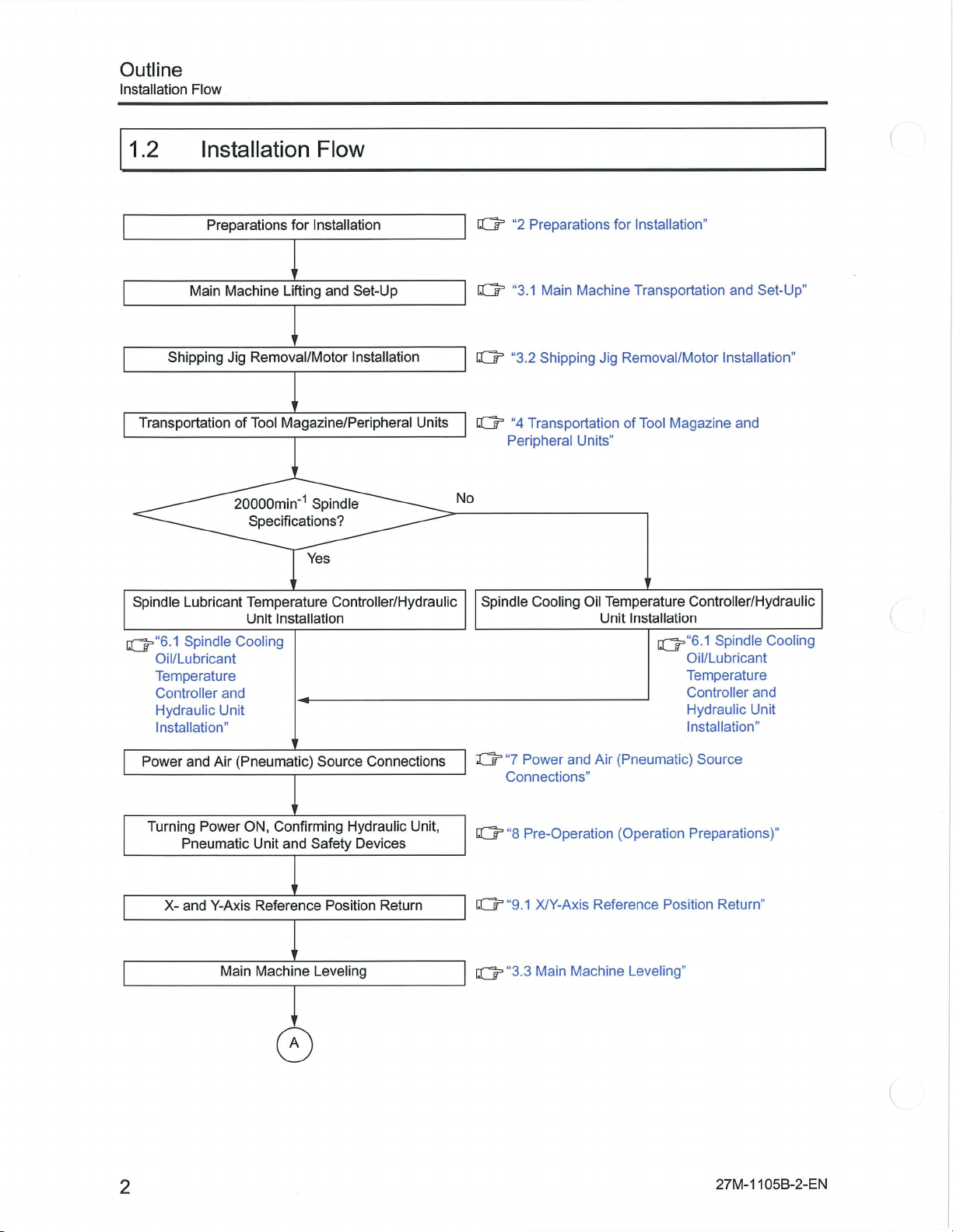
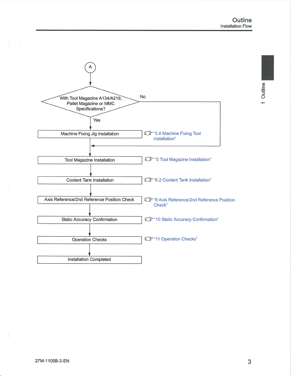
1.2
Main
Shipping
Transportation
Spindle
lQ=“6.1
Lubricant
Spindle
Oil/Lubricant
Temperature
Controller
Hydraulic
Installation”
Installation
Preparations
for
I
Machine
Jig
of
20000min‘1
Cooling
and
Unit
Lifting
Removal/Motor
Magazine/Peripheral
Tool
Specifications?
Temperature
Unit
Installation
Flow
Installation
Set-Up
and
Installation
Spindle
Yes
Controller/Hydraulic
Units
No
tjh
O’
IQ3
Q=
Spindle
Preparations
“2
Main
“3.1
“3.2
Shipping
Transportation
”4
Peripheral
Cooling
for
Machine
Jig
Removal/Motor
Units”
Temperature
Oil
Unit
Installation”
Transportation
of
Tool
Magazine
Controller/Hydraulic
Installation
IQ=“6.1
Oil/Lubricant
Temperature
Controller
Hydraulic
Installation”
Set-Up”
and
Installation”
and
Spindle
Cooling
and
Unit
2
Power
Turning
X-
(Pneumatic)
Air
and
Power
Pneumatic
and
Y-Axis
Main
ON,
Confirming
Unit
and
Reference
Machine
A
Source
Hydraulic
Safety
Position
Leveling
Connections
Unit,
Devices
Return
"7
Ch
Connections”
tQ=
“8
[ÿh“9.1
Q=“3.3
Power
and
Air
Pre-Operation
X/Y-Axis
Main
Reference
Machine
(Pneumatic)
(Operation
Position
Leveling”
Source
Preparations)”
Return”
105B-2-EN
27M-1
Page 3
Tool
With
Pallet
Machine
A
Magazine
Magazine
Specifications?
Fixing
A134/A219,
or
Yes
Jig
Installation
MMC
No
C
dr"
“3.4
Machine
Installation”
Fixing
Tool
Outline
Installation
Flow
I
c
3
O
Axis
Reference/2nd
Static
Magazine
Tool
Coolant
Accuracy
Operation
Installation
Installation
Tank
Installation
Reference
Confirmation
Checks
Completed
Position
Check
HJT”
“5
0=“6.2
“9
0=
Check”
CQ3
“10
Cdr’“11
Tool
Magazine
Coolant
Axis
Reference/2nd
Static
Accuracy
Operation
Installation”
Tank
Installation”
Checks”
Reference
Confirmation”
Position
27M-1
105B-3-EN
3
Page 4
Preparations
Confirmation
Preparations
of
for
Installation
for
Installation
2
2.1
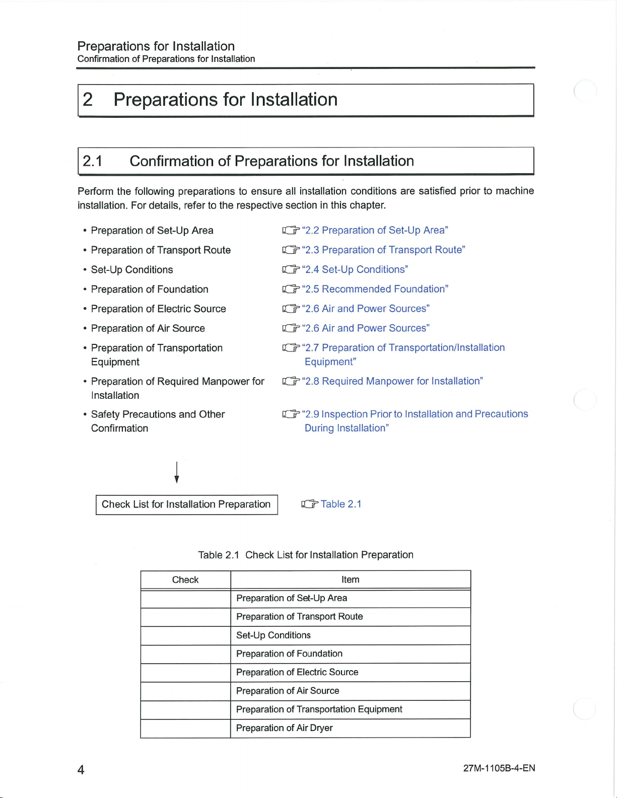
Perform
installation.
•
•
•
•
•
•
•
•
Preparations
Confirmation
following
the
For
Preparation
PreparationofTransport
Set-Up
Preparation
Preparation
Preparation
PreparationofTransportation
Equipment
PreparationofRequired
Installation
of
Conditions
of
of
of
preparations
details,
refer
Set-Up
Foundation
Electric
Source
Air
for
of
the
to
Area
Route
Source
Manpower
Installation
Preparations
ensure
to
respective
for
all
installation
sectioninthis
“2.2
O’
“2.3
0°
G=“2.4
Q=“2.5
0”“2.6
“2.6
KJ
G=“2.7
Equipment”
0=“2.8
Installation
for
are
conditions
chapter.
Preparation
PreparationofTransport
Set-Up
Recommended
and
Air
and
Air
Preparation
Required
of
Conditions”
Power
Power
of
Manpower
satisfied
Set-Up
Foundation”
Sources”
Sources”
Transportation/lnstallation
Area”
for
prior
Route”
Installation”
machine
to
Safety
•
Confirmation
Precautions
Check
List
and
i
for
Installation
Check
Other
Preparation
Table
Check
2.1
Preparation
Preparation
Set-Up
Preparation
Preparation
Preparation
“2.9
O’
During
O’
for
List
Set-Up
of
Transport
of
Conditions
Foundation
of
Electric
of
Air
of
Inspection
Installation”
Table
2.1
Installation
Item
Area
Route
Source
Source
Prior
Preparation
Installation
to
and
Precautions
Transportation
Preparation
Preparation
of
of
Air
Dryer
4
Equipment
27M-1
105B-4-EN
Page 5
Preparations
Preparation
for
Installation
Set-Up
of
Area
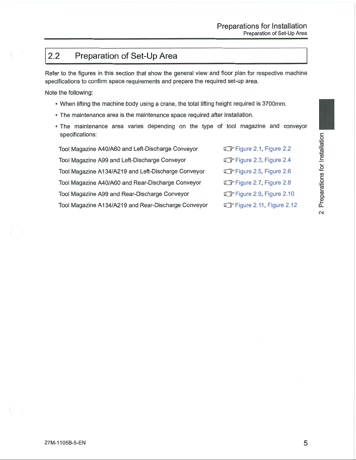
2.2
Refer
specifications
Note
•
•
•
Preparation
to
the
following:
the
When
The
maintenance
maintenance
The
specifications:
Tool
Magazine
Tool
Magazine
Magazine
Tool
Magazine
Tool
Tool
Magazine
Magazine
Tool
figures
to
confirm
lifting
this
in
space
the
machine
area
A40/A60
and
A99
A134/A219
A40/A60
and
A99
A134/A219
of
Set-Up
section
area
that
requirements
using
body
is
the
maintenance
varies
Left-Discharge
and
Left-Discharge
Left-Discharge
and
Rear-Discharge
and
Rear-Discharge
and
Rear-Discharge
Area
show
the
and
crane,
a
space
depending
Conveyor
Conveyor
general
prepare
the
total
required
on
the
Conveyor
Conveyor
Conveyor
Conveyor
view
the
lifting
and
required
height
after
type
floor
plan
set-up
required
installation.
tool
of
Q=
Figure
Figure
0=
Figure
0°
Figure
O’
Figure
0=
Figure
O’
respective
for
area.
is
magazine
2.1,
2.3,
2.5,
2.7,
2.9,
2.11,
3700mm.
and
Figure
Figure
Figure
Figure
Figure
Figure
machine
conveyor
2.2
2.4
2.6
2.8
2.10
2.12
B
.1
TO
3
c
a
B
ro
o.
2
Q.
CM
27M-1
105B-5-EN
5
Page 6
Preparations
Preparation
Set-Up
of
installation
for
Area
General
in
8
os
CN
FI
CN
View:
I
n
Magazine
Tool
Maintenance
j,
,,
2195
5
Height
3865
A40/A60
>
5265
1610
Left-Discharge
and
Conveyor
o
in
CN
!
'O
F
(N
;
in
co
co
I
!
l!
1400
]
Ln
£
m
o\
LTI
(Tool
600
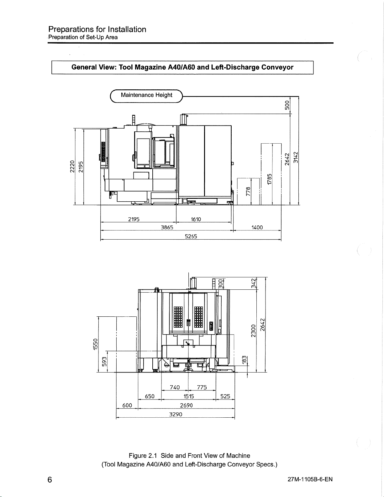
Figure
Magazine
A
¥
650
Side
2.1
A40/A60
740
1515
2690
3290
and
Front
Left-Discharge
and
775
a
View
o
.n
i
525
of
m
co
Machine
Conveyor
CN
m
CN
O
O
CN
m
CN
Specs.)
27M-1
6
105B-6-EN
Page 7
Preparations
Preparation
Installation
for
of
Set-Up
Area
Air
Source
(With
in
co
o
s
e*
o
8
in
ON
in
rn
o
O
'O
1
in
04
in
Air
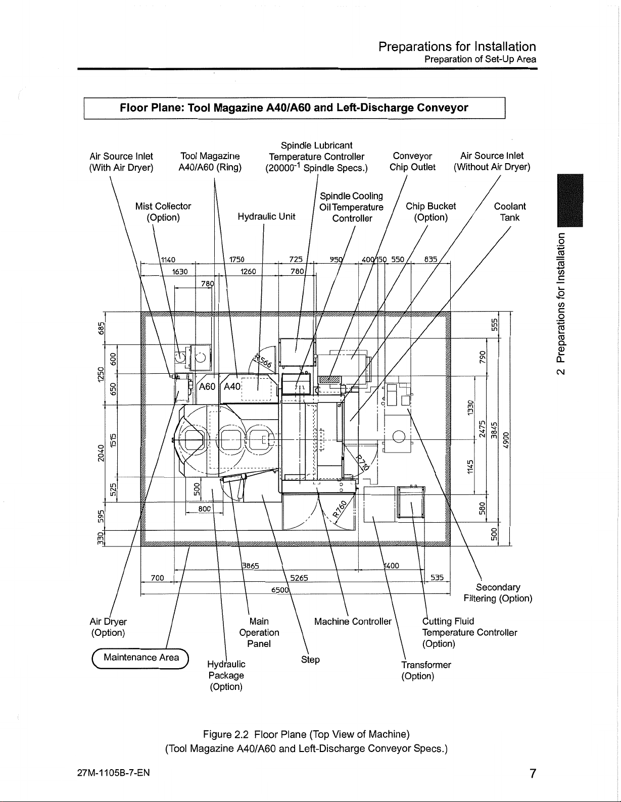
Floor
Inlet
Dryer)
Mist
/
Plane:
Collector
(Option)
11140
V//////M
r
1
y/////////?A
Tool
Tool
A40/A60
1630
o
in
Magazine
Magazine
(Ring)
O
A60
A40
\
800
Hydraulic
1750
1260
K
A40/A60
Spindle
Temperature
(20000"1
Unit
4
%
])
725
780
jr
t
and
Lubricant
Controller
Spindle
Spindle
Oil
1
WM
%
\
Left-Discharge
Specs.)
Cooling
Temperature
Controller
951
40<
150
I
L
W/zr/A.
i
7
/
3
/
w
ii
_
\
Conveyor
Conveyor
Chip
Outlet
Bucket
Chip
(Option)
/
msttfm
7
835
4-
550
0
n
1
__
_
;
Air
Source
(Without
s
P
I
\
§
tn
s
Inlet
Dryer)
Air
Coolant
Tank
in
in
in
CO
o
m
5
o
in
I
§
|
8
C
a
c
.2
s
ro
2
Q.
CM
Air
(Option)
(
27M-1
Dryer
Maintenance
105B-7-EN
700
Area
(Tool
)
Figure
Magazine
Hydraulic
Package
(Option)
2.2
A40/A60
3865
6501
Main
Operation
Panel
Floor
5265
Machine
Step
Plane
and
(Top
Left-Discharge
View
1400.
Controller
of
Machine)
Conveyor
535
Cutting
Temperature
(Option)
Transformer
(Option)
Specs.)
Filtering
Fluid
Secondary
(Option)
Controller
7
Page 8
Preparations
Preparation
Set-Up
of
for
Installation
Area
General
in
CM
os
CM
CM
View:
1
F
Tool
Maintenance
Q
2195
Magazine
Height
I
r;_
-J
3865
A99
,
Left-Discharge
and
lOgBL
1610
5265
3
mi*
JB
Conveyor
CO
:
1400
O
in
CM
in
oo
(N
sQ
CM
S
I
>
I
Ji
m
CM
SO
CM
(Tool
g
£
DU
880
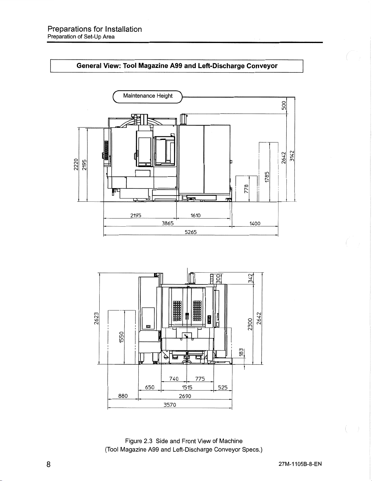
Figure
Magazine
650
2.3
~E
A99
740
3570
Side
and
and
Left-Discharge
ITW
II
775
1515
2690
Front
View
I
525
Machine
of
Conveyor
CM
m
o
m
CM
m
Specs.)
CM
sO
CM
105B-8-EN
8
27M-1
Page 9
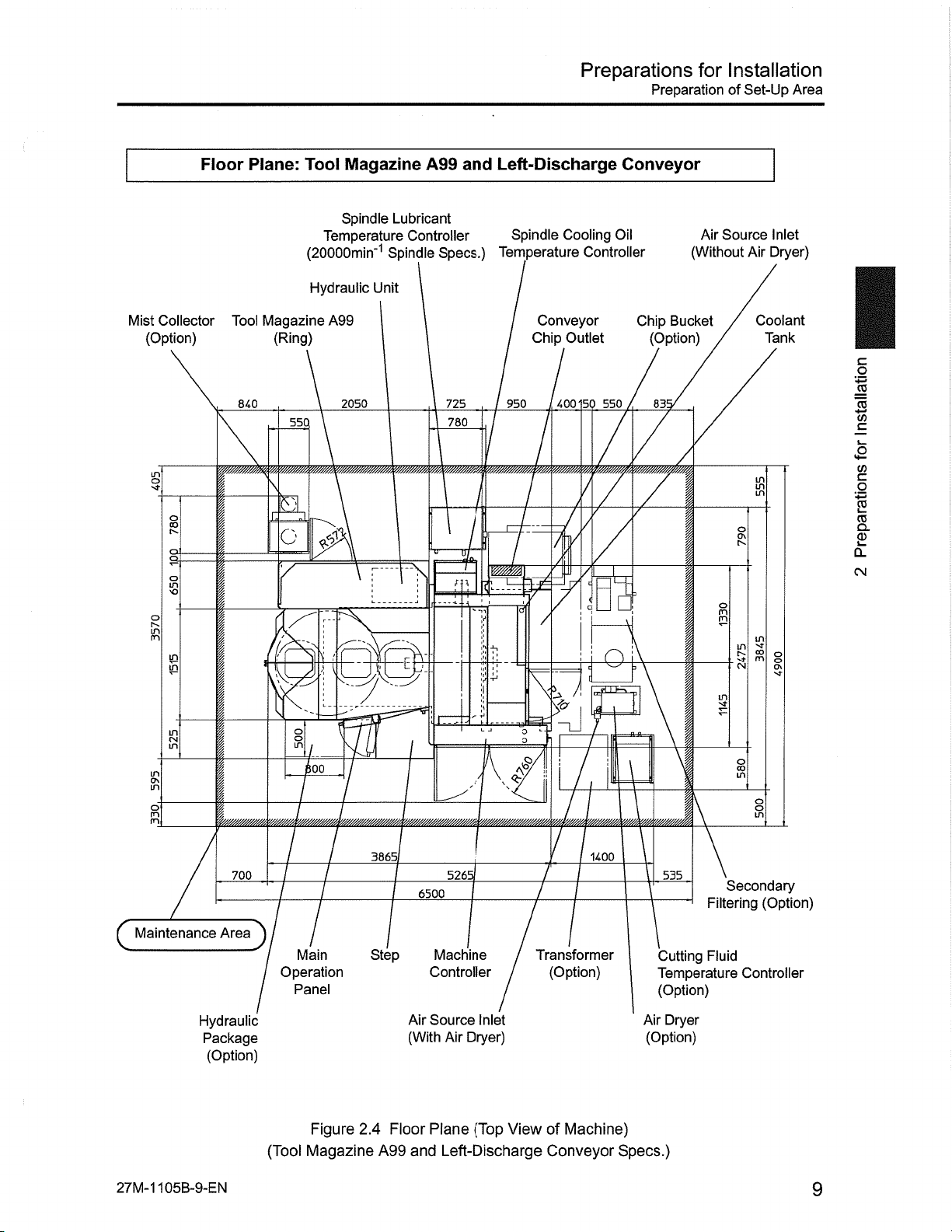
Preparations
Preparation
for
Installation
Set-Up
of
Area
Mist
(Option)
s
o
R
in
o\
in
s
m
Floor
Collector
§
S
>o
£
in
in
CM
in
i
I
Plane:
Tool
840
700
Tool
(20000min'1
Hydraulic
Magazine
(Ring)
55Q
\
B.
1
O
21
s
o
in
\oo_
Magazine
Spindle
Temperature
Unit
A99
2050
1
V.
386;
A99
Lubricant
Controller
Spindle
"EH-
6500
and
Specs.)
725
780
m
5265
Left-Discharge
Spindle
Temperature
950
WtM
Cooling
Conveyor
Chip
Outlet
400
Ww//////m.
/
/
ti
•i
%
;
i:
*
/
Oil
Controller
550
150
/
j
/
S
n
•
/
!
_
i
1400
Conveyor
Chip
Bucket
(Option)
13!
/
~\
7
I
7
\
535
Source
Air
(Without
P
I
Secondary
Filtering
Air
Coolant
in
in
§
t".
in
CO
§
m
CM
§
in
o
Inlet
Dryer)
Tank
o
5
(Option)
§
§
a
w
a
w
%
s
£
CL
CM
Maintenance
(
Hydraulic
Package
(Option)
27M-1105B-9-EN
Area
)
(Tool
Main
Operation
Panel
Figure
Magazine
2.4
Step
A99
Air
(With
Floor
and
Machine
Controller
Source
Plane
Air
Inlet
Dryer)
(Top
Left-Discharge
Transformer
View
of
Conveyor
(Option)
Machine)
Cutting
Temperature
(Option)
Air
(Option)
Specs.)
Fluid
Controller
Dryer
9
Page 10
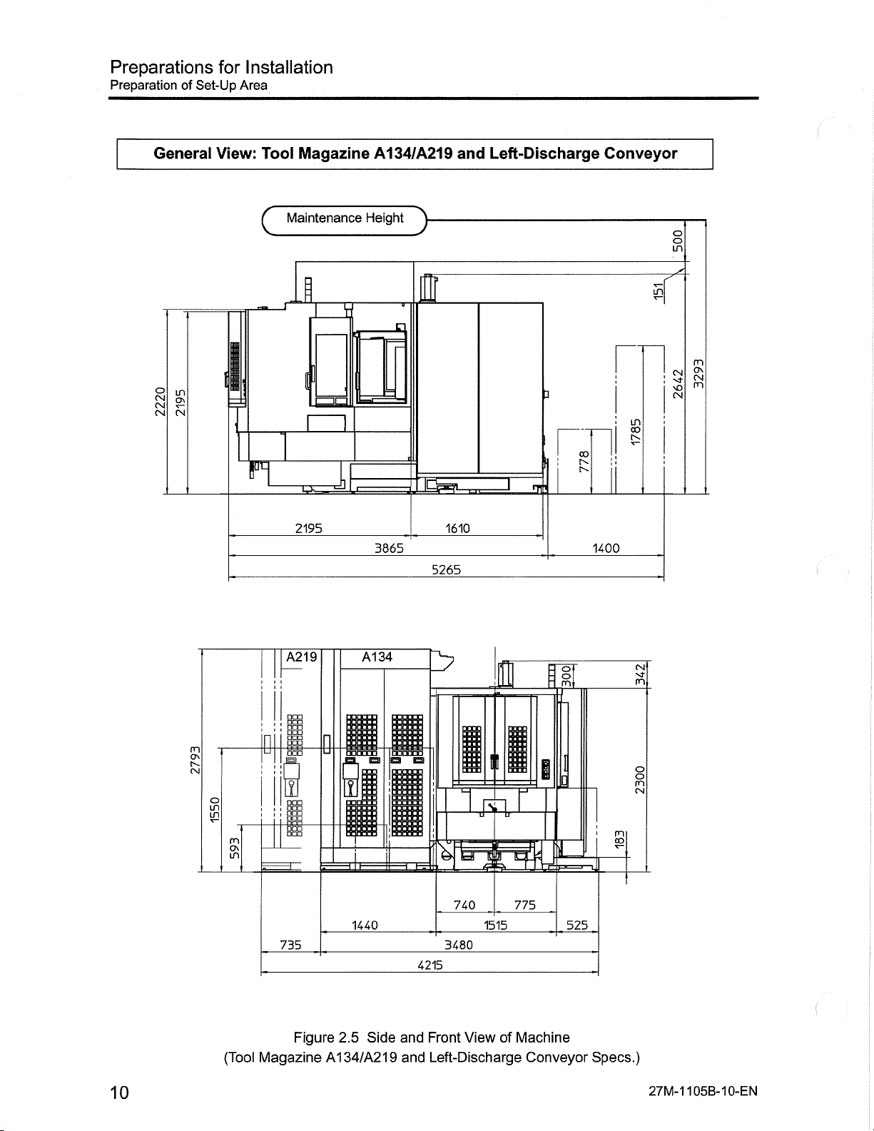
Preparations
Preparation
of
Set-Up
Installation
for
Area
General
in
CM
ON
CM
CM
View:
Tool
F
Magazine
Maintenance
I
2195
A134/A219
Height
3865
1610
5265
Left-Discharge
and
Conveyor
O
m
w
m
ON
CM
5
!
m
co
NO
CM
3
in
I
CO
nj'
1400
m
ON
CM
LO
\P
m
ON
in
(Tool
A219
1
1
755
Figure
Magazine
A134
D
1440
2.5
Side
A134/A219
740
3480
4215
and
Front
Left-Discharge
and
I
775
1515
ViewofMachine
Conveyor
i
o
m
525
mi
co
Specs.)
CM
m
O
m
CM
10
27M-1
105B-10-EN
Page 11
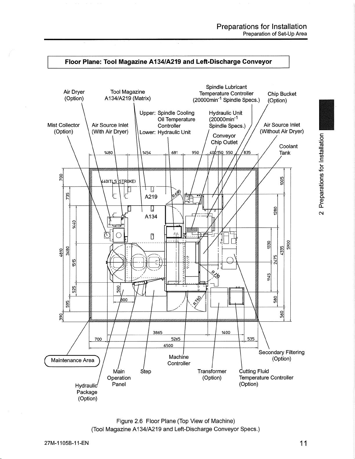
Preparations
Preparation
for
Installation
Set-Up
of
Area
Mist
(Option)
Floor
Dryer
Air
(Option)
Collector
o
s
o
2
S
rn
5
£
in
Plane:
Air
(With
Tool
Tool
A134/A219
Air
1480
140IT
Inlet
Dryer)
'STROKE)
US
Source
O
4.
Magazine
Magazine
(Matrix)
Upper:
Lower:
1454
I
7
-
1
A134/A219
Spindle
Temperature
Oil
Controller
Hydraulic
IT
A219
IT
A134
-Ei
Cooling
681
m
Left-Discharge
and
Temperature
(20000min'1
Unit
950
mwA
/
X
Spindle
Lubricant
Spindle
Hydraulic
Controller
Unit
(20000min"1
Conveyor
Chip
Outlet
550
50
Specs.)
Spindle
40/
7
/
/
/!
y
/
I
s
n\
Conveyor
Specs.)
(Without
/
/
835
/
i
Chip
(Option)
Source
Air
§
£
I
in
3
Bucket
Inlet
Dryer)
Air
Coolant
Tank
i
in
'is
1
a
a
Q.
U
§
To
c
2
2
CM
s
Maintenance
(
105B-1
27M-1
in
o\
in
Area
Hydraulii
Package
(Option)
(Tool
1-EN
700
)
iOO.
Main
Operation
Panel
Figure
Magazine
X
3865
Step
Floor
2.6
A134/A219
5265
6500
Machine
Controller
(Top
Plane
Left-Discharge
and
$
ii
Transformer
(Option)
of
View
1400
Machine)
Conveyor
I
535
Secondary
Cutting
Temperature
(Option)
Fluid
Specs.)
§
§
in
Filtering
(Option)
Controller
11
Page 12

Preparations
Preparation
of
Set-Up
Installation
for
Area
General
in
8
o\
CM
CM
CM
View:
Maintenance
n
Tool
2195
Magazine
Height
A40/A60
'y
1
4940
5440
1610
Rear-Discharge
and
3
ml
1135
Conveyor
K
CM
500
O
in
CM
m
5
>o
in
CM
co
&
8
£
(Tool
m
o\
in
Figure
Magazine
600
ft
OH
650
2.7
Side
A40/A60
JO
740
1515
2690
3290
and
Front
Rear-Discharge
and
o
m
775
525
ViewofMachine
Conveyor
mi
col
Specs.)
CM
m
O
m
CM
CM
<3
CM
12
27M-1105B-12-EN
Page 13

Preparations
Preparation
Installation
for
of
Set-Up
Area
Air
Source
(With
Dryer
Air
(Option)
vO
o
'O
8
?!
s
O
in
CM
in
in
o\
in
Floor
Air
I
|
Plane:
Inlet
Dryer)
Mist
_
'///////////z,
7
700
Tool
Tool
A40/A60
Collector
(Option)
1140
163(
v/MM
o
o
v////////ÿy//////////////#ÿÿ
Magazine
Magazine
(Ring)
Hydraulic
I
1750
1260
780
A60
[*4°[77
loo
38P5
A40/A60
Spindle
Temperature
(20000min‘1
Unit
780)
r-T,
-E
l
>440
6700
Rear-Discharge
and
Lubricant
Controller
Spindle
Spindle
Oil
Controller
Specs.)
Cooling
Temperature
2750
2395
1600
m
Prjg
=i
i:
I
0
]E2lg_
/
Conveyor
Source
Air
(Without
Coolant
Tank
400
Air
660
1415
Inlet
Dryer)
Filtering
Secondary
(Option)
o
I
B
j
7
o
in
(M
0\
a
C
a
2
S.
2
Q.
CM
1
CO
o
m
m
fit
3
o\
CM
f
/
y/M
1P5
32!
J
I
175
560
CM
3
rn
CM
•o
m
Maintenance
Area
c
Hydraulic
Package
27M-1105B-13-EN
)
(Option)
(Tool
Main
Operation
Panel
Figure
Magazine
Step
Machine
Controller
Floor
2.8
A40/A60
Transformer
(Option)
(Top
Plane
Rear-Discharge
and
Conveyor
Outlet
Chip
View
of
Cutting
Temperature
Controller
Machine)
Conveyor
Fluid
(Option)
Specs.)
Chip
(Option)
Bucket
13
Page 14

Preparations
Preparation
of
Set-Up
Installation
for
Area
8
CM
(N
General
in
ON
CN
View:
Maintenance
Tool
Magazine
Height
A99
'y
and
Rear-Discharge
Conveyor
O
in
E_F
CN
R
£
CNJ
m
'O
CN
in
00
\
]
r=
:
F
2
2195
4940
5440
1610
1135
500
m
CN
NO
CN
(Tool
8
!P
880
Figure
Magazine
2.9
A99
m
650
740
3570
Side
and
and
Rear-Discharge
m
1515
2690
Front
775
View
m.
I
525
of
Machine
Conveyor
CN
m
o
m
CN
m
oo
Specs.)
CN
NO
CN
14
27M-1
105B-14-EN
Page 15

Preparations
Preparation
Installation
for
of
Set-Up
Area
Air
Source
(With
Air
(Option)
o
s
tv.
s
-o
O
in
m
8
Air
Dryer
Floor
Inlet
Dryer)
Mist
|840
Plane:
Tool
Collector
(Option)
55Q
a
o
Tool
Magazine
(Ring)
(050
1
V.
Magazine
A99
Temperature
(20000min'1
Hydraulic
A99
Spindle
Unit
m
/
r-T,
Rear-Discharge
and
Lubricant
Controller
Spindle
/
j
I
n
Specs.)
Spindle
Oil
Cooling
Temperature
Controller
2395
1600
MMWMMMWW.
r~
i
o
Air
Source
(Without
355
£Zf
3
Conveyor
Inlet
Air
Dryer)
Secondary
(Option)
660
/00
MW.
/
I
Filtering
Coolant
(N
ON
1
m
ON
(N
CN
Tank
s
o
CO
m
rn
I
§
'ÿs
1
w
c
a
2
CD
Q_
eg
8
o\
in
CM
in
in
o\
in
n
Maintenance
(
1
///////////////,
r
700
Area
),
Hydraulic
Package
(Option)
o
in
_8(
ym/////////m//m///////ÿ
Main
Operation
Panel
Figure
(Tool
Magazine
3805
2.10
A99
Step
Floor
//////////////////////,
5440
6700
Machine
Controller
Transformer
(Option)
Plane
and
Rear-Discharge
1
(Top
A*?
my/////////,
View
:
;
/////»////////.
113!
Controller
Conveyor
Outlet
Chip
of
Machine)
Conveyor
:1
ymym.
325
175
Cutting
Temperature
Fluid
(Option)
Specs.)
w/A.
560
4
2
l
rn
>4-
Chip
(Option)
£
in
Bucket
27M-1
05B-1
1
5-EN
15
Page 16

Preparations
Preparation
Set-Up
of
Installation
for
Area
General
in
8
o\
CM
S
CM
View:
r
Magazine
Tool
Maintenance
T
2195
A134/A219
Height
4940
>
if
5440
1610
Rear-Discharge
and
2
i
1135
Conveyor
\\
500
o
in
m
ON
CM
CM
m
>o
CM
-£
£
CM
£
:
m
ON
CM
8
£
(Tool
m
ON
in
Magazine
A219
BBS
BOO
BBB
735
Figure
A134
m
1440
Side
2.11
A134/A219
3480
4215
Front
and
Rear-Discharge
and
J
I!
r=rik_
740
ViewofMachine
775
1515
Conveyor
o
m
i
525
Specs.)
CM
m
o
m
CM
m
oo
16
27M-1
105B-16-EN
Page 17

Preparations
Preparation
Installation
for
Set-Up
of
Area
Mist
O
tv
1
vf
§
Floor
Air
(Option)
Collector
(Option)
in
m
tv
1
g
8
K3
in
in
o\
in
Plane:
Dryer
\
\
|440(TL
I
_
Source
Air
(With
1480
wyyy/tWy
;
Tool
Air
Magazine
Magazine
Tool
A134/A219
(Matrix)
Inlet
Dryer)
11454
7
J
o
HREi
o
*00
yyyyyyyy,
A134/A219
(20000min‘1
Upper:
Temperature
Lower:
Spindle
Hydraulic
w,
A219
u
A134
a
_
and
Spindle
Temperature
Controller
751
Lubricant
Spindle
Cooling
Unit
l#
7
a
£
4
-4
l
$
'ft
Rear-Discharge
Controller
Specs.)
Oil
27t
/Air
1600
Source
(Without
7
Inlet
Air
Dryer)
5
RE
vyyyyyyyyyyyyyyyy'yyyy
Conveyor
Secondary
Filtering
(Option)
/
Coolant
/
Tank
/
660
;00,/
535
880
V/M.
/
/
7
'/yyyyyyyy.
Secondary
Filtering
(Option)
20000min‘1
Spindle
1
O
tv
m
o\
eg
CN
Specs.
55
§
oo
in
in
o
I
rn
oo
\Q
in
I
s
I
2
c
a
W
B
E
£
Q.
CM
Maintenance
(
27M-1105B-17-EN
Area
Hydraulic
Package
(Option)
700
)/
(Tool
Main
Operation
Panel
Figure
Magazine
3805J
Step
Floor
2.12
A134/A219
5440
6700
Machine
Controller
Transformer
(Option)
Plane
(Top
Rear-Discharge
and
View
1131
Conveyor
Outlet
Chip
of
Machine)
Conveyor
32!
175
560
Cutting
Temperature
Controller
Specs.)
Fluid
(Option)
Chip
(Option)
Bucket
17
Page 18

Preparations
Preparation
of
Transport
for
Installation
Route
2.3
Prepare
machine
For
Tool
The
tool
Machine
(Tool
Magazine
Machine
container
Machine
(Tool
Magazine
Machine
container
Preparation
the
machine
size
shipment
Magazine
magazine
Table
when
when
(Tool
when
when
(Tool
A40/A60/A99:
A40/A60/A99
2.2
Item
transported
A40)
transported
Magazine
transported
A60)
transported
Magazine
of
transport
dimensions.
Machine
A40)
A60)
by
in
by
in
Size
truck
truck
Transport
route
(adequate
O’
Table
2.2,
(ring)
is
assembled
Shipment
Height
2642mm
2300mm
2642mm
2413mm
Route
space
Figure
Dimensions
2.13
onto
Height
Lifting
Equipment
(O’
3700mm
3700mm
3700mm
3700mm
transporting
for
machine
the
(Tool
With
NOTE)
prior
Magazine
2260mm
2144mm
2260mm
2144mm
machine),
to
shipment.
referring
A40/A60/A99)
Width
to
Depth
3865mm
3865mm
3865mm
3865mm
the
Machine
(Tool
Machine
container
For
Tool
The
tool
Machine
Machine
container
Tool
Magazine
Tool
Magazine
when
Magazine
when
(Tool
Magazine
magazine
Table
when
when
transported
A99)
transported
Magazine
A134/A219
A134/A219
2.3
Machine
Item
transported
transported
34
A1
A21
9
by
in
A99)
by
in
truck
O’
is
truck
not
Size
2642mm
2642mm
Table
2.3,
installed
Shipment
Height
2642mm
2300mm
3795mm
2795mm
Figure
onto
2.13,
the
Dimensions
(O’
3700mm
3700mm
Figure
machine
(Tool
Height
With
Lifting
Equipment
NOTE)
3700mm
3700mm
3795mm
3795mm
2391mm
2144mm
2.14
priortoshipment.
Magazine
A134/A219)
Width
2260mm
2122mm
1440mm
2175mm
3865mm
3865mm
Depth
3865mm
3865mm
1454mm
1454mm
18
27M-1
105B-18-EN
Page 19

Preparations
PreparationofTransport
Installation
for
Route
Lifting
•
•
•
•
NOTE:
When
lifting
Units
of
Magazine
Tool
Spindle
4.3
Spindle
Coolant
lifting
space
Cooling
Lubricant
Tank
the
main
500mm
is
1
A134/A219
Temperature
Oil
Temperature
Figure
Ch
machine
the
plus
w
(Matrix)
4.4
using
height
w
Q=
Controller
Controller
crane,
a
the
with
Figure
2.14
(Other
than
(20000min"1
necessary
the
lifting
equipment.
The
for
The
the
2.2
20000min'1
Spindle
height
total
dimensions
the
tool
dimensions
of
type
and
Table
Spindle
Specs.)
requiredtoprovide
magazine
magazine.
tool
2.3.
0°
shown
A40
differ
Specs.)
Figure
in
depending
the
(Ring)
Refer
O’
4.3
Figure
specs.
to
Figure
adequate
are
upon
Table
I
o
1
i
.E
a
c
.2
1
8.
2
CL
CM
Ns
&
(
Required
Crane
Height
Lifting
for
m
Using
,o
ivUl
o
>
cirÿriL
s*1
O'
§
3
I
I
o
27M-1
05B-1
1
9-EN
Figure
2.13
Lifting
of
Main
Machine
When
2173
2364
Transported
19
Page 20

Preparations
Preparation
Transport
of
for
Installation
Route
Tool
Magazine
C£
A134/A219
5
(Matrix)
o
o
m
ON
LTI
ON
fn
20
Figure
2.14
735
Depth
Lifting
of
1440
2175
O’
Tool
(A134)
(A219)
2.3
Table
Magazines
(Matrix)
When
Transported
27M-1
05B-20-EN
1
(
Page 21

Preparations
Installation
for
Set-Up
Conditions
2.4
Confirm
Ambient
Relative
Temperature
Well-illuminated
Free
Dust-free
Available
Available
Adequate
Required
Set-Up
the
following
Temperature
Humidity
direct
from
space
space
space
electrical
set-up
Fluctuation
sunlight
for
storing
for
maintenance
around
power
Conditions
location
Table
Set-Up
10°C
RH
Less
raw
machine
sources
Location
to
40°C
35%to70%
than
materials,
work
open
to
environmental
and
2.4
and
(Optimum
(No
1°C/30
minutes
finished
completely
doors
conditions
Set-Up
workpiece
Conditions
Environmental
20±1°C)
Temp:
Condensation)
(Range
and
Conditions
which
does
tools
prior
machine
to
influence
not
set-up.
machining.)
I
1
%
.E
a
S
2.
2
CL
CM
§
c
A
level
foundation
Appropriate
strong
distance
from
enough
factory
support
to
air
ducting/inlets
the
weight
(Air
of
the
Flow)
machine
27M-1105B-21-EN
21
Page 22

Preparations
Recommended
Foundation
for
Installation
2.5
Construct
Symbol
a
b
c
e
f
Recommended
appropriate
an
*
Ground
Foundation
Machine
Machine
Jet
Anchor
Insulated
Vibration
Anchor
Jet
Jet
Anchor
Foundation
Recommended
Rubble
foundation,
Resistance
Thickness
Support
Tool
Fixing
for
Machine
Foundation
Tool
for
for
Tool
Reinforcing
Concrete
Foundation
referring
Table
2.5
Item
Point
Surrounding
from
Magazine
Magazine
Bar
to
Table
Recommended
(Matrix)
A134
A219
(Matrix)
2.5,
Table
Foundation
5
ton/m2
300mm
points
3
points
3
points
6
Small
points
4
points
4
Vertical
FC180
Medium
2.6,
or
above
(M16:
crushed
(M16:
(M16:
and
Horizontal:
standard
or
large
Figure
Description
Anchor)
Jet
stone
Anchor)
Jet
Anchor)
Jet
and
size
2.15
<|>22mm
above
crushed
and
(O3
Figure
(Q=
NOTE
stones
2.16.
NOTE
1)
1)
A
D
E
Indicates
NOTE:
These
1
2
When
3
Machine
magazine,
Dimensions
4
installation
recommended
5
As
this
the
professional
according
Leveling
Concrete
Magazine
(Tool
Concrete
Magazine
Concrete
Magazine
symbol
the
values
machine
(*)
are
fixing
pallet
indicated
foundation.
values.
machine
surrounding
civil
the
to
Concrete
Weight
Weight
A134
Weight
A219
used
Thickness
Foundation
of
A40/A60/A99)
Foundation
of
(Q=
NOTE
Foundation
of
(O’
NOTE
in
Figure
2.15
1)
1)
and
reference/recommended
tool
equipped
is
tools
must
magazine
operates
area,
engineer
actual
in
depending
ground
with
used
be
MMC
or
foundation
this
The
foundation
high-speeds,
at
determine
to
conditions
to
(tO“3.4
Machine
for
Tool
for
for
Tool
Figure
magazine
secure
upon
the
values.
the
Machine
drawing
drawings
vibration
the
final
and
possible
50mm
7.1tons
0.9ton
0.9ton
2.16.
(ring),
A99
machinetothe
Fixing
minimum
are
on
generated
foundation
foundation
influence
(Q*
NOTE
support
a
Tool
following
the
by
and
dimension
on
1)
is
leg
when
floor
Installation”).
requirements
pages
machine
ground
operation
conditions.
requirements
surrounding
the
required.
installing
a
for
show
as
area.
matrix
a
good
only
may
affect
Consult
they
solid
the
a
vary
22
27M-1
05B-22-EN
1
Page 23

Preparations
Recommended
for
Installation
Foundation
Foundation
A
A+D
A+D+E
Tool
o
LH
8
R
LH
£
Area
Magazine
Table
2.6
Foundation
Foundation
Foundation
A40/A60/A99
trr
b
Foundation
Machine
for
Machine
for
Machine
for
and
b
vr
a
a
iim
\
r
b
AreabyMachine
Machine
Magazine
Tool
and
Tool
Tool
Magazine
Magazine
and
and
Specs.
Specifications
A40/A60/A99
A134
A219
Left-/Rear-Discharge
A
Vrl?
in
m
oo
8
8
O
in
CM
X
CM
(Matrix)
(Matrix)
Conveyor
8
CM
(Ring)
75
%
a
.2
CL
CM
§
c
c
2
£
27M-1
(Tool
105B-23-EN
470
I50
mmmimimiimmk
Magazine
820
1595
2550
250X9=2250
250
Figure
A40/A60
775
Rubble
2.15
/A99
485
7
Foundation
Left-/Rear-Discharge
and
Drawing
8
in
CNI
Wi|
Leveling
Sj
ml
—
Reinforcing
Vertical
<(>1
and
0x250
Reinforced
o
o
Concrete
Conveyor
(Double):
Bar
Horizontal
Concrete
Specs.)
23
Page 24

Preparations
Recommended
Foundation
Installation
for
Tool
Magazine
LTI
m
in
vO
LH
in
s
GO
m
a
A134/A219
g
in
LH
in
e,
/"
b
Left/Rear-Discharge
and
f
e
f
0
m
T
a
lu
\
t
b-
A
\if
in
m
oo
Conveyor
(N
Jl_
X
CM
£
CN.
450
350
300,
100
50
E
D
24
(Tool
[50
Magazine
820
470
2550
250X9=2250
250
flllllllllllllttllllllilllllli
Figure
A134/A219
775
1595
Rubble
2.16
and
485
Foundation
Left-/Rear-Discharge
7
Drawing
in
¥
Leveling
Reinforcing
Vertical
(]>
-
and
10x250
Reinforced
a
Concrete
Conveyor
Bar
(Double):
Horizontal
Concrete
Specs.)
27M-1
05B-24-EN
1
Page 25

Preparations
Air
for
Installation
and
Power
Sources
2.6
Item
Electrical
Maximum
Consumption
Total
Requirement
Circuit
Power
Ground
Ground
Air
Source
Power
Power
Breaker
Cable
Cable
and
Power
AC200/220V
50/60Hz
48kVA
Approx.
The
48x0.6=29kVA
93x0.6
225A
60mm2
or
38mm2
cable
Ground
30mm2
0.5-0.
-
410L/min:
-
Dew
-
NOTE:
Clean
Sources
Table
10%
±
±
2%
(Standard)
93kVA
(including
power
actual
56kVA
=
more
or
or
more
SP39-10021J)
resistance
more
or
8MPa
ANR
point
temperature:
air
(free
from
and
are
options)
cables
cables
condition)
or
iron
and
Power
Description
shown
less
rust)
Air
2.7
options)
requirements
(Standard)
(including
insulated
(600V
(600V-flame-retardant
100Q
insulated
(600V
(Standard
-20°C
solvent
Sources
below:
specified
poly-flex
specified
required.
is
JIS
by
insulated
JIS
by
C3307)
cables
C3307)
made
HITACHI
by
I
1
&
a
£
o.
CM
§
w
c
E
8.
E
Air
Air
Air
Source
Dryer
Filter
Equivalent
particles
Max.
-
particles
Max.
-
particles
Max.
-
point
Dew
-
oil
Max.
-
NOTE:
The
machine
feature.
When
may
Standard
(without
With
Must
5pm
Periodic
maintenance
occurina
scale)
Scale
be
ordered
0.3pm
+
grade
the
to
number/1
number/1
number/1
pressure:
max.
at
concentration:
requires
+
the
maintenance
the
of
period
short
except
remover
water
IS02.5.2
m3:
Below
m3:
Below
m3:
Below
Below
0.1mg/m3
above
must
filters
time.
of
Required
Standard
prepared
when
specified
or
air
neglected,
is
410
460
10
(diameter:
1000
1000000
7°C
(Absolute
less
quality.
performed
be
Flow
Air
by
by
IS08573-1
0.001
(diameter:
(diameter:
The
air
to
pollution
filter
(L/min:
Using
Spindle
customer.
(equivalent
x
<
0.0005<
0.0001
Pressure:
are
filters
maintain
ANR)
Through
Frequently
Air
600
690
<
0.005mm)
<
x
<
0.8MPa)
installed
optimum
an
damage
and
JIS
to
0.001mm)
<
0.0005mm)
x
as
a
to
With
8392-1)
B
standard
supply.
air
filter
the
Blow
Air
660
750
27M-1
105B-25-EN
25
Page 26

Preparations
Air
and
Power
Sources
NOTE:
The
air
air
quality
quality
varies
values
Installation
for
according
satisfy
the
to
the
required
factory
values.
circumstances.
Use
particle
a
counter
confirm
to
that
the
The
air
Earth
Terminal
quality
Connecting
Point
Size:
specified
M8
CD
ISO
by
Electric
Connection
Terminal
Power
Size:
8573-1
Source
Point
M8
\
(equivalent
rFk
*
to
i*
JIS
8329-1)
B
recommended.
is
"
'
t
Air
RC1/2
Setting:
Inlet
Dryer)
(PT1/2)
0.5MPa
Source
Air
(Without
Size:
Pressure
Air
Figure
O
rvj
Dryer
2.17
§i
_WfeD
o
Power
Source
'Qo
D
Detailed
Source
-Air
(With
Air
RC1/2
Size:
To
Source
Air
Main
Machine
Connection
off1
D
View
Inlet
Dryer)
(PT1/2)
Inlet
Point
of
of
and
°
A
Air
A
Source
N
X
Inlet
o
8
(With
Air
Dryer)
26
27M-1
105B-26-EN
Page 27

Preparation
Preparations
Transportation/Installation
of
for
Installation
Equipment
2.7
Prepare
and
withstanding
If
the
Preparation
equipment
required
representative
Parts/Tools
Transfer
Necessary
Measurement
Machine
Machine
Machine
To
Equipment:
Tools:
(Without
(Tool
(Tool
such
the
weight
transportation
for
further
Be
Prepared
Crane,
Tools
supplied
Tools:
Precision
Tool
Magazine)
Magazine
Magazine
of
crane,
as
a
of
the
assistance.
Forklift,
standard
Level,
A40)
A60)
Transportation/Installation
fork
lift
machine
equipment
Table
2.8
Lifting
Equipment
with
Indicator
Table
Item
truck,
prior
cannot
Required
the
machine
Machine
2.9
casters/rollers,
and
to
machine
be
Equipment
transportation.
prepared,
Weigh
Equipment
capable
contact
of
supporting
your
Makino
Weight
7400kg
7600kg
7800kg
the
size
service
EJ
o
1
B
w
a
£
2
S.
2
CL
CM
Machine
Tool
Magazine
Tool
Magazine
Spindle
(Ring
Magazine
Spindle
Spindle
(Matrix
Hydraulic
Coolant
and
Cutting
Coolant
and
Cutting
Coolant
and
Cutting
Coolant
and
Cutting
Coolant
and
Cutting
(Tool
Magazine
A134
A219
Cooling
Lubricant
Cooling
Magazine
Unit
(Ring
Tank
Left
Fluid
Tank
Left
Fluid
Tank
Left
Fluid
Tank
Rear
Fluid
Tank
Rear
Fluid
A99)
Oil
Temperature
and
other
than
Temperature
Oil
Temperature
and
other
Magazine
Discharge
Temperature
Discharge
Temperature
Discharge
Temperature
Discharge
Temperature
Discharge
Temperature
Controller
20000min'1
Controller
Controller
20000min'1
than
Specs.,
(Through-Spindle
Controller:
(Through-Spindle
Controller)
(Through-Spindle
Controller)
(Through-Spindle
Controller:
(Through-Spindle
Controller)
(20000min‘1
Matrix
Standard)
Standard)
Spindle
and
Specs.)
Spindle
Hydraulic
Spindle
Specs.)
Magazine
1.5MPa/Without
3.0MPa/Without
7.0MPa/Without
1.5MPa/Without
3.0MPa/Without
Specs.)
Unit
20000min"1
and
Workpiece
Workpiece
Workpiece
Workpiece
Workpiece
Spindle
Cleaning
Cleaning
Cleaning
Cleaning
Cleaning
Specs.)
Gun
Gun
Gun
Gun
Gun
8500kg
2100kg
2700kg
95kg
280kg
160kg
60kg
370kg
420kg
437kg
610kg
660kg
Coolant
and
*
27M-1105B-27-EN
Tank
1
3kg
Fluid
to
Cutting
Add
temperature
Rear
coolant
controller.
Discharge
Temperature
weight
tank
(Through-Spindle
Controller)
listed
above
7.0MPa/Without
installing
when
Workpiece
workpiece
a
Cleaning
cleaning
Gun
gun
or
cutting
677kg
fluid
27
Page 28

Preparations
Required
Manpower
for
installation
for
Installation
2.8
The
following
installation
the
table
This
work
Machine
Tool
Magazine
Spindle
and
Spindle
Spindle
Hydraulic
Coolant
Cooling
Hydraulic
Specs.)
Lubricant
Tank
Required
table
of
the
a51
below.
schedule
Work
Installation
A134/A219
Oil
Unit
(Other
Temperature
(20000min‘1
Unit
Manpower
shows
may
Temperature
the
machine.
change
Item
than
Spindle
for
minimum
Prepare/reserve
for
different
Table
Controller
20000min"1
Controller
and
Specs.)
Installation
required
installation
2.10
manpower,
manpower
Work
Required
Manpower
1
2
1
1
1
necessary
environments
Schedule
time
and
for
and
Required
(hrs/person)
22
4
1
1
4
the
number
installation
machine
Time
of
by
referring
options.
Required
(day/person)
3
1
1
1
1
days
Day
for
to
Operation
Checks
After
Installation
1
4
1
28
27M-1
105B-28-EN
Page 29

Inspection
Prior
Installation
to
Preparations
and
Precautions
Installation
for
During
Installation
2.9
previous
The
inspection
This
section
checked
thoroughly
2.9.1
Confirm
2.9.2
A
the
Inspect
•
•
Check
Unassisted
Inspection
Installation
“Safety”
general.
in
specifically
when
performing
and
observe
Inspection
following
any
for
attachments
all
Handling
Lifting
Installation
to
safety
Read
precautions
chapter
Read
describes
installation.
the
Prior
describes
“Safety”
the
safety
PriortoInstallation
prior
to
points
machine
Heavy
of
and
installation
damage.
accessory
Components
safety
chapter
precautions
and
to
work:
units
and
precautions
thoroughly
for
understand
the
safety.
shipping
ensure
with
Precautions
machine
for
to
prior
installation
section
this
operation,
installation.
as
and
packing
and
well
During
as
“Safety”
the
check
maintenance
needs
what
precautions
list.
to
and
be
I
I
I
*
a
c
.2
2
8.
2
o.
CM
Avoid
lifting
persons
stacker,
B
The
components
damage
following
according
pallet
Lifting
breakage
to
points:
Forklifts
•
Do
not
•
machine
Safety
•
hook
All
•
personnel.
the
Use
•
specialized
Use
•
Confirm
•
center
keeping
heavy
of
trolley
a
with
rope
of
being
components
the
must
attempt
whileitis
helmets
and
crane
weight
the
gravity,
of
weight
the
machine
circumstances.
to
the
or
chain
Crane
during
lost,
and
always
to
enter
being
shoes
and
linking
within
tools
of
attach
as
components
block,
the
them
may
and
operated
be
area
the
transferred.
must
tasks
range
the
where
component
the
wires
stable
by
Use
depending
lifting
of
falling.
required
prescribed.
guaranteed
as
The
result
by
qualified
under
worn
be
its
rated
of
to
possible.
person
one
mechanical
on
the
falling
serious
in
lifted
all
at
crane
capacity.
be
lifted.
to
components
personnel
times.
carry
heavy
the
for
alone.
Lift
equipment
requirements.
can
heavy
of
injury
machine.
lifting
Then,
the
components
or
only.
Exercise
must
considering
weight
them
such
result
death.
be
of
the
with
as
a
in
may
careful
Pay
extreme
performed
the
presumed
the
component
help
crane,
the
caution
two
of
electric
balance
cause
attention
for
by
only
position
and
more
or
forklift
heavy
of
irreparable
the
to
lifted
the
qualified
the
of
slowly,
lift
27M-1
Clearly
•
105B-29-EN
indicate
off-limit
zones
and
keep
unauthorized
all
personnel
from
entering
these
areas.
29
Page 30

Preparations
Inspection
PriortoInstallation
Installation
for
and
Precautions
During
Installation
C
Forklift
using
When
or
overturning
Safety
•
Forklifts
•
Use
•
Widen
•
convenient
•
Do
of
When
•
2.9.3
When
following
workingathigh
Safety
•
Lifting
a
helmets
the
the
attempt
not
the
forklift.
lifting
Working
points:
helmets
forklift
forklift.
the
must
forklift
forks
a
a
carry
to
and
always
within
height
to
component
and
heavy
Pay
shoes
be
the
much
as
as
possible.
balanceanun-balanced
Elevated
at
locations,
shoes
components,
careful
must
operated
range
as
a
with
falling
must
there
attentiontothe
be
worn
by
its
of
possible
forklift,
all
at
qualified
capacity.
rated
to
load
stay
allow
out
Locations
can
resultinserious
worn
be
at
all
is
the
following
times.
personnel
weight
the
extra
with
the
area
of
times.
danger
points:
only.
personnel
for
injury.
of
be
to
which
the
Pay
falling
load
raisedtobe
riding
entrance
careful
on
the
is
attention
the
from
stable
opposite
prohibited.
at
to
forks
as
side
the
Use
•
other.
•
Extreme
positions
Use
•
2.9.4
When
working
catching
worn
at
2.9.5
When
working
the
machine
between
•
Confirm
warning
stable
a
safety
Working
clothing
all
times.
Working
moving
steps
shouldbetaken
care
performing
when
rope
in
or
low
protruding
on
combination,
in
may
resultindeath
parts.
the
location
starting
when
or
a
stepladder.
when
in
Confined
confined
Groups
in
careful
Pay
and
to
Do
avoid
to
using
tasks
performing
Spaces
spaces,
machine
lack
tasks
operate
parts.
communication
of
duetoaccidents
attentiontothe
being
the
stand
not
slippingonoily
both
hands
tasksonthe
care
take
Proper
following
performed
machine.
pail,
on
a
or
cans
surfaces,
freely.
splashguard.
striking
avoid
to
attire,
work
when
a
turning
suchaselectric
points:
other
by
personnel
boxes
or
etc.
your
safety
ON
shock,
and
head,
helmet
the
and
stacked
ensure
shoulders
and
power
main
falling,
or
giveaclearly
on
top
stable
or
shoes
or
being
each
of
working
arms,
or
be
must
operating
caught
audible
30
Display
•
power
clear
switch
work
and
description
the
main
warnings
operation
and
panel
signs
etc.
so
in
that
front
the
of
the
content
crane
of
operation
can
work
panel,
understood.
be
105B-30-EN
27M-1
the
main
Page 31

Inspection
Preparations
PriortoInstallation
and
Precautions
Installation
for
Installation
During
2.9.6
A
WARNING
Work
-
-
Requiring
-Some
installation
adequate
OFF
Turn
ON.
power
Perform
person.
Machine
procedures
precautions
power
the
“Lockout/Tagout”
are
supply
Operation
can
only
takenatall
except
for
prevent
to
preformed
be
times.
some
accidental
inspections
operation
by
that
moving
must
of
the
machine.
the
performed
be
machine
by
Ensure
the
with
another
u
§
i
a
«
B
CO
to
S>
Q.
CM
27M-1
105B-31-EN
31
Page 32

Main
Main
Machine
Machine
Installation
Transportation
and
Set-Up
3
3.1
Confirm
•
Inspect
Check
•
A
WARNING
Rear
(Tool
Magazine
Main
Main
the
following
for
all
Upper
Rope,
Side)
Machine
Machine
points
any
machine
attachments
the
Keep
-
no
higher
Lift
-
Prevent
-
Do
-
All
-
times,
impact
remove
not
procedures
ensure
to
Installation
Transportation
installation
to
prior
damage.
and
accessory
machine
than
with
the
are
operator
Rear
(Operator
level.
necessary.
nearby
shipping
be
to
Upper
Lifting
work:
units
with
objects.
prior
jig
performed
safety.
Rope
Door
Side)
Bar
Set-Up
and
the
shipping
installationofthe
to
pairs,
in
and
packing
and
machine.
communication
clear
check
list.
maintained
all
at
Front
Rope
Center
Socket
(S'
II
Trough
Cover
Head
Rope
Rear
Upper
Upper
Rear
(Operator
Door
Rope
Side)
Rear
(Tool
Magazine
Rope
Side)
4
il
A
w
Rear
.Shackle
Lifting
Rope
Bar
II
\
*
i
i
JO
o
\
\
Bed
Cap
Screws
Lifting
Jo
Plate
32
Figure
3.1
Lifting
of
Main
Machine
27M-1
05B-32-EN
1
Page 33

Parts/Tools
To
Be
Prepared
(Lifting/Transportation):
Name
For
Tool
Main
Magazine
Part
Main
Machine
Machine
Transportation
A40/A60/A99
No.
Installation
Set-Up
and
Q'ty
Front
Rope
Rear
Rope
Upper
Rear
Rear
Upper
Lifting
Plate
Socket
Head
Washer
Shackle
Lifting
Bar
Parts/Tools
Rope
Front
Rear
Rope
Upper
Rear
Upper
Rear
Lifting
Plate
Rope
Rope
Cap
To
Rope
Rope
(Operator
(Tool
Screw
Be
Prepared
(Operator
(Tool
Door
Side)
Magazine
Side)
(Lifting/Transportation):
Name
Side)
Door
Magazine
Side)
For
Tool
21M74B705=1
21M74A702
T13M-0734E
T13M-0272E
T27M74AA701
Z271B1114130
Z275A11
Z259B7240000
T13M-0269D
Magazine
21M74B705=1
21
T13M-0272E
T13M-0272E
T27M74AA701
01400
A134/A219
Part
No.
M74A702
QP
2
1
1
1
2
2
1
1
Q'ty
1
2
1
1
1
§
1
to
c
IE
3
c
to
co
Socket
Head
Washer
Shackle
Lifting
Bar
Parts/Tools
Leveling
Leveling
Flat
Protective
Shaft
Shaft
Coil
Washer
Adjuster
Base
Bolt
Point
(only
Holder
Spring
(only
Pad
Set
Cap
To
Screw
Metal
Tool
(only
(only
Tool
(only
Screw
Be
Prepared
Magazine
Tool
Tool
Magazine
Magazine
Tool
(Installation)
Name
A99)
Magazine
A99)
Magazine
A99)
A99)
A99)
Z271B1114130
Z275A1101400
Z259B7240000
T
1
3M-0269D
No.
Part
13M30B209
1
3M30B424
Z272A1112020
13M30B703=1
27M30C2021
Z392C1
Z392F1
Z275A1
Z392O1916130
800001
840060
102000
2
2
1
1
Q'ty
3
3
3
3
1
1
1
1
1
Plate
27M-1
(only
Tool
1
05B-33-EN
Magazine
A99)
27M30C2022
2
33
Page 34

Main
Main
Machine
Machine
Installation
Transportation
and
Set-Up
3.1.1
Main
Machine
Main
Dd
1
2)
3)
4)
5)
6)
7)
8)
9)
and
Lifting
Machine
Figure
Remove
)
Remove
Secure
cap
head
Mount
the
Lift
main
the
the
Insert
side.
Mount
plate.
lifting
Mount
Place
the
boltismountedoneach
foundation.
Set-Up
Lifting
3.1,
Figure
top
the
center
the
lifting
the
screws
ropes
the
assembled
machine.
front
the
front
rear
two
the
three
cover.
to
rope
rope
leveling
3.2,
trough
plate
and
the
lifting
ropes
Set-Up
and
Figure
cover.
to
the
washers.
lifting
equipment
from
the
onto
the
to
bases
of
3.3
main
as
bar
top
shackle
the
bedonthe
(
Q=
the
three
Procedure
machine
shown
cover
using
and
in
a
into
rear
Figure
machine
(bed)
Figure
crane,
the
secure
side
3.8)
support
the
with
.
3.1
move
and
machining
the
shackle
machine.
of
which
in
points
socket
two
it
chamber
to
leveling
a
on
near
the
the
10)
11)
This
Next,
Removal”).
the
Lift
3.2.
Confirm
30mm~35mm
completes
remove
machine
the
height
(
the
the
carefully
Id
main
lifting
using
between
Figure
machine
2.13).
equipment
a
crane
the
lifting
floor
and
(Id
and
and
set-up
place
the
procedure.
“3.1.2
as
it
main
Lifting
shown
machine
Equipment
Figure
in
is
34
27M-1
105B-34-EN
Page 35

Main
Main
Machine
Machine
Transportation
Installation
Set-Up
and
Support
in
o
n
n
Xt-
n
Point
I
470
7///////////////////////////y
4
////////////////,
+
1595
Y//S/////S//////////////////////*
+
.+
+
++
485
!
I
j
|
S\
t
Support
;
Point
Support
o
rx
O
Point
in
Ch
o
CN
n
rn
oo
§
1
B
£
•g
CD
.E
CD
CO
27M-1105B-35-EN
Figure
3.2
2550
Main
Machine
Installation
35
Page 36

Main
Main
Machine
Machine
Installation
Transportation
and
Set-Up
3.1.2
Lifting
Equipment
Removal
When
1)
perform
reverse
Lift
2)
of
•
•
Mount
3)
•
Mount
4)
completes
This
Next,
Installation”).
Removal
Procedure
the
the
order
assembled
the
main
the
Take
precautions
window
Take
precautions
the
column
of
the
Mount
prevent
the
the
remove
main
main
to
machine.
[2]
the
of
center
gasket
coolant
cover
top
lifting
the
the
shipping
0=
machine
machine
remove
lifting
to
prevent
machining
to
prevent
chamber.
trough
on
leakage.
[1].
equipment
is
placed
lifting
ropes
chamber.
the
3.1,
the
Figure
the
equipment
cover.
center
the
removal
(Q=
jigs
and
from
using
front
rear
trough
“3.2
Figure
on
the
set-up
the
a
rope
rope
procedure.
Shipping
3.3
foundation
procedure
main
machine.
crane,
from
hitting
from
cover
and
specified,
as
step
in
move
and
hitting
Jig
the
parts
the
apply
Removal/Motor
3-8
outside
it
ceiling
inside
silicon
(
in
to
Top
Cover
[1]
Ceiling
Window
[2]
36
Figure
3.3
Lifting
Equipment
Removal
27M-1
1
05B-36-EN
 Loading...