

Page 1
Model:MN/E-1A
Makeblock Co., Ltd.
Technical support: support@makeblock.com
Address: 3rd Floor, Building C3, Nanshan iPark, No.1001 Xueyuan Avenue,
Nanshan District, Shenzhen, Guangdong Province, China
www.makeblock.com
@Makeblock
@Makeblock@Makeblock
D1.2.12_KD010032000
Page 2
neuron
creative lab kit
k
J
c
o
i
y
t
s
K
n
b
o
B
n
u
o
t
t
Ultrasonic Sensor
Wireless R
Wireless T
USER MANUAL
r
G
o
y
C
a
r
a
e
m
r
P
o
I
s
R
n
e
S
e
S
r
o
u
i
t
l
s
i
M
o
B
r
u
e
z
z
s
r
n
o
e
S
L
r
i
o
g
s
h
n
t
e
S
r
T
o
s
e
n
m
e
p
S
R
D
G
E
B
L
Display
r
C
o
o
s
l
n
o
e
r
S
r
S
o
s
o
n
u
e
n
d
S
r
H
o
u
s
m
n
e
i
t
S
u
r
e
p
L
i
r
E
t
D
S
Dual IR Detector
Funny Touch
EL Wire Driver
DC Motor Driver
Servo Driver
Bluetooth
r
P
e
o
w
r
P
e
o
w
W
i
F
i
-
Page 3

creative lab kit
P01
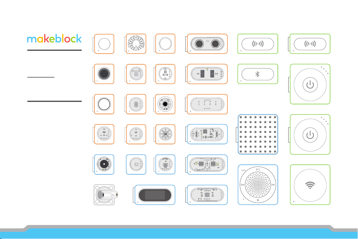
Parts List
P05
Meet Your Neuron
Colorful Blocks With Diverse Functions
Easy Connection
Oine Creating
Online Programming
P09
Block Introductions
Energy & Communication Blocks
Input Blocks
Output Blocks
P43
Accessories
P47
FAQ
Page 4
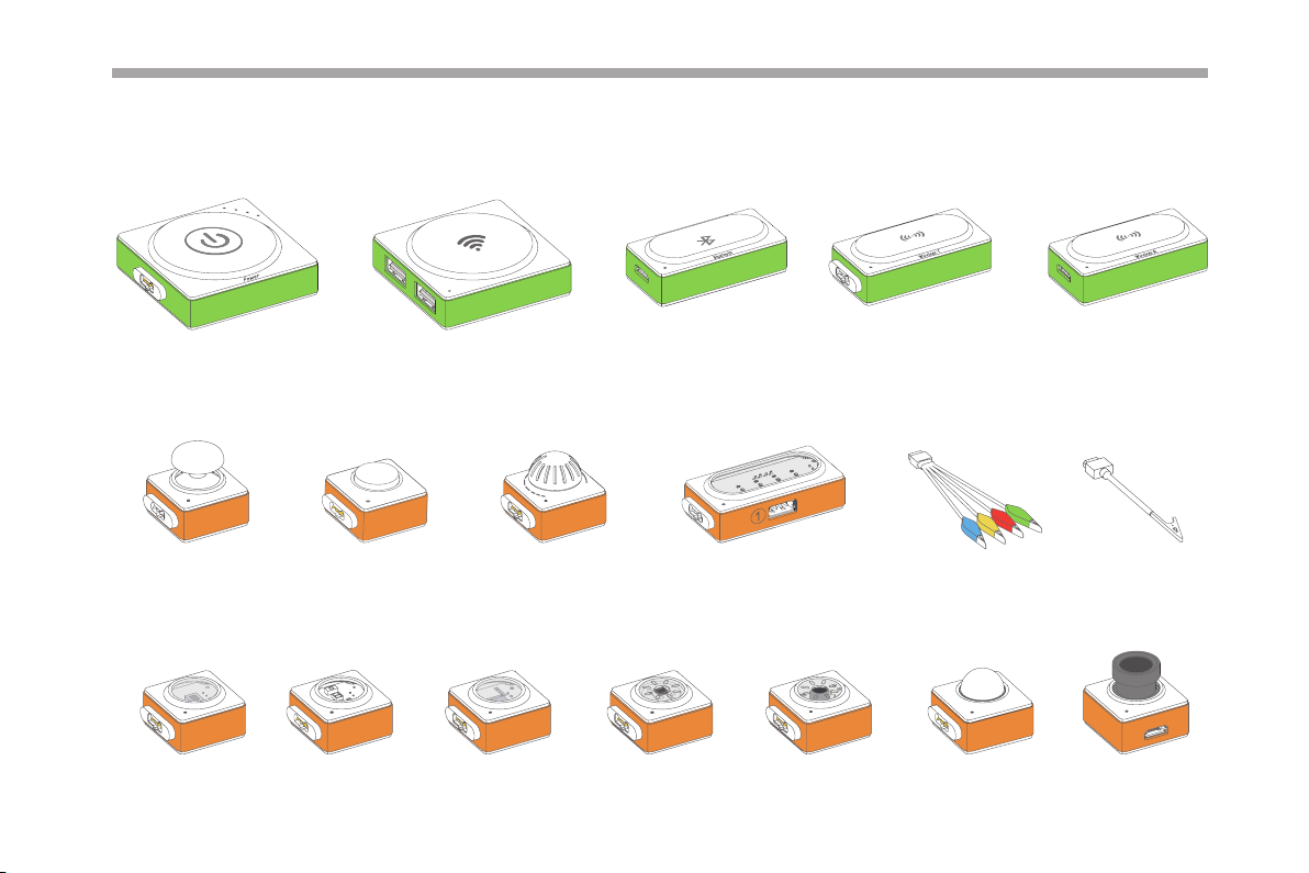
Parts List
i
F
-
i
W
Power × 2
o
J
Joystick
h
g
i
L
k
c
i
t
s
y
B
Button Knob Funny Touch Funny Switches GND Wire
r
o
s
n
e
S
t
r
o
s
n
e
S
r
o
l
o
C
Wi-Fi Bluetooth Wireless Transmitter Wireless Receiver
y
n
n
u
F
h
c
u
o
T
y
n
n
o
t
t
u
o
r
y
G
b
o
n
K
r
o
s
n
e
S
r
o
s
n
e
S
e
r
u
t
i
m
u
H
n
u
F
r
o
s
n
e
S
d
n
u
o
S
r
o
s
n
e
S
R
I
P
D
N
G
a
C
Light Sensor Color Sensor Gyro Sensor Humiture Sensor Sound Sensor PIR Sensor Camera
a
r
e
m
01
Page 5
r
o
s
n
e
S
p
m
e
T
p
m
e
T
e
r
u
t
s
i
o
M
l
i
o
S
il
o
S
or
ect
Det
IR
l
a
u
D
r
o
ns
Se
onic
ras
t
Ul
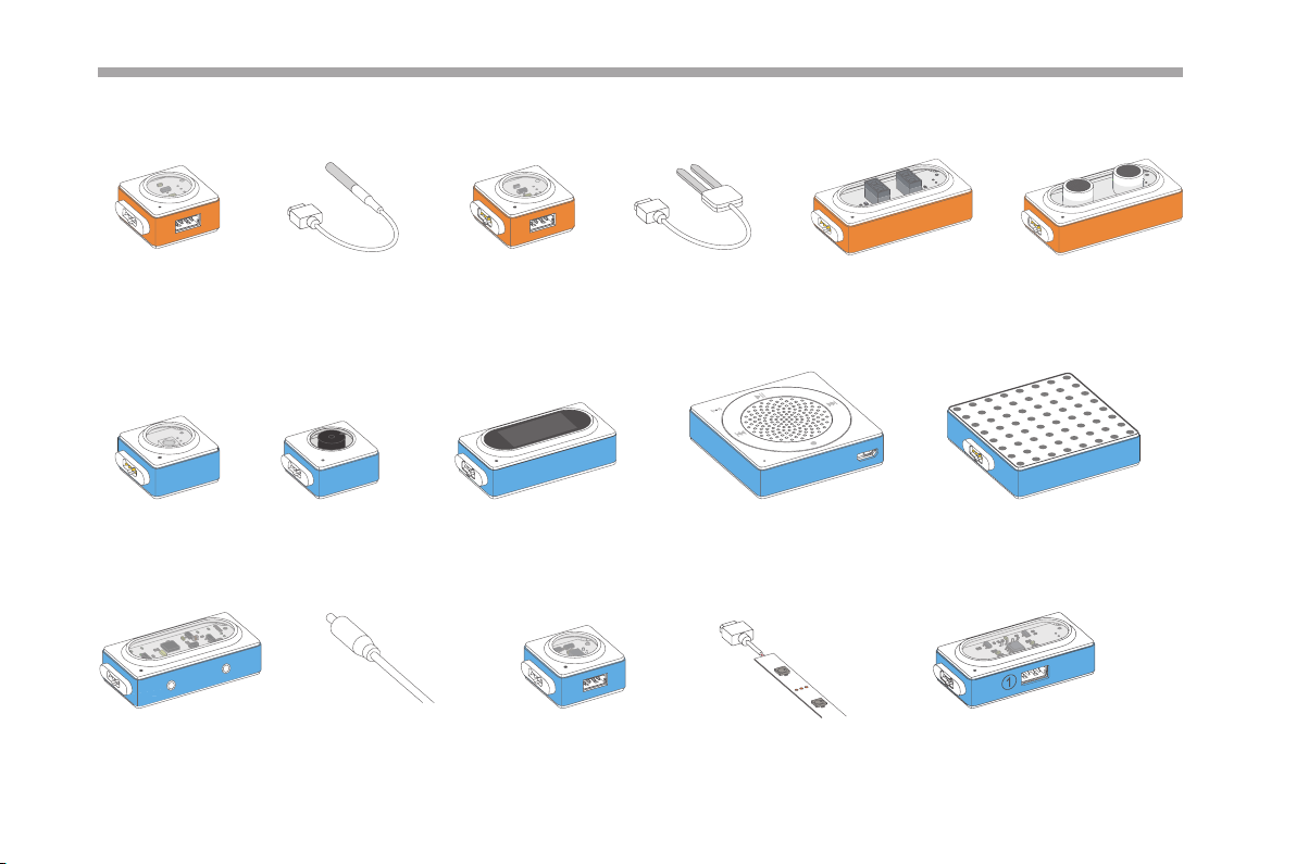
Temperature Sensor Temperature Probe Soil Moisture Probe
D
E
L
B
G
R
r
e
z
z
u
B
RGB LED Mic & Speaker LED Panel
ver
EL Wire Dri
Soil Moisture Sensor Dual IR Detector Ultrasonic Sensor
lay
p
Dis
DisplayBuzzer
p
i
r
t
S
D
E
L
EL Wire Driver EL Wire × 8 LED Strip Driver LED Strip
02
D
E
L
Servo Driver
Dual Servo Driver
Page 6
r
Drive
r
o
v
r
e
S
DC Mot
o
r
o
t
o
M
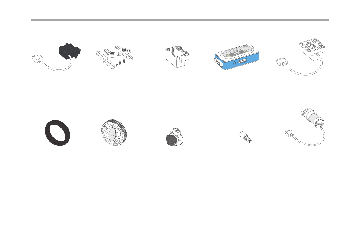
Servo × 2 Servo Accessory Pack × 2 Servo Bracket × 2 Dual DC Motor Driver DC Motor× 2
Water
Pump
Tyre × 2 Wheel Hub × 2 Mini Auxiliary Wheel × 2 Crossed Shaft Connector × 2
Water Pump
03
Page 7
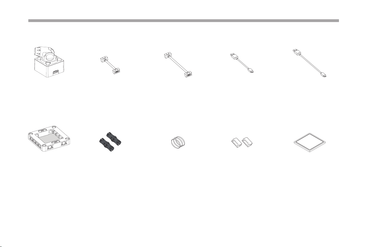
Laser Pointer Magnet Wire (10cm) × 3 Magnet Wire (20cm) ×3 USB Cable (20cm) × 2 USB Cable (100cm) × 2
Gel Pad
Neuron Board ×9
04
Friction Pin Connector ×36 Rubber Band ×20
Fixed Clip ×4 Gel Pad ×6
Page 8
Meet Your Neuron
Colorful Blocks With Diverse Functions
The Neuron is classied into three categories according to color.
Energy & Communication blocks (Green): Provide power to other blocks. The communication block contains a Micro USB interface,
you can connect the block to power bank or power adapter via USB cable to power the other blocks. The communication blocks also
supply diverse wireless communication modes.
Input blocks (Orange): The input blocks collect information (such as sound and light) from the environment and send signals to change
the output.
Output blocks (Blue): The output blocks receive signals from input blocks, and then do something, such as lighting up, moving or
making a sound.
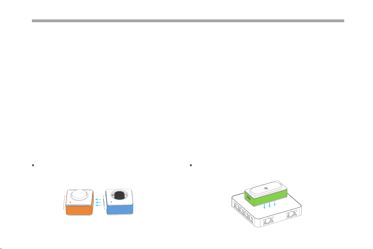
Easy Connection
Magnetically snap together, experience the magic of Neuron.
r
e
B
z
u
B
n
u
o
t
t
z
The back of the block is magnetically designed to snap the block
to a Neuron board or magnetic board.
Bluetooth
05
Page 9
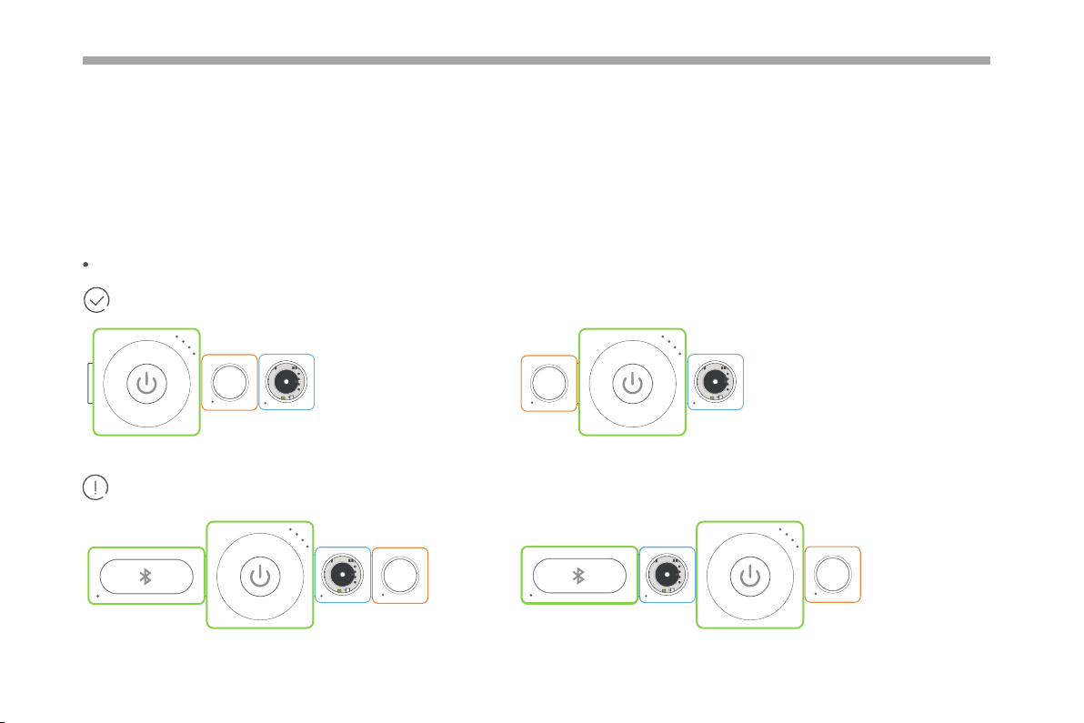
Oine Creating
When you use the Neuron without any software, you can create rich eects with the preset program. In this mode, the Neuron block
will behave according to the data it received from the previous block.
Connection rules in this mode:
The input block (orange) must be connected on the left side of the output block (blue).
Working normally!
06
B
B
n
u
o
t
t
r
P
e
o
w
r
u
e
z
z
B
n
u
o
t
t
r
P
e
o
w
Only working when you program the blocks via Makeblock Neuron app or mBlock.
B
r
Bluetooth
B
u
e
z
z
r
P
e
o
w
n
u
o
t
t
Bluetooth
Bluetooth
B
r
u
e
z
z
B
B
r
r
u
e
u
e
z
z
z
z
r
P
e
o
w
B
n
u
o
t
t
Page 10
An input block can aect multiple output blocks, while an output block can only receive signals from its nearest input block.
B
B
B
n
u
o
t
t
r
P
e
o
w
r
u
e
z
z
r
P
e
o
w
Funny Touch
Both the buzzer and LED
panel can receive signal
from the button.
n
u
o
t
t
The buzzer can only
receive signal from
the button.
B
r
u
e
z
z
07
Page 11
Online Programming
Connect the Neuron blocks to a tablet, smart phone or computer, either with Bluetooth or Wi-Fi block, then you can design how
Neuron blocks interact with each other by using Makeblock Neuron app or mBlock. Reboot the power block to switch online
programming to oine creating.
Makeblock Neuron App
With Makeblock Neuron app, you can invent with electronic blocks without programming knowledge. You only need to draw lines
between electronic blocks in an intuitive interface. This process also develops logical thinking and intuition about electronics.
Furthermore, Makeblock Neuron app may control your invention remotely via its IoT (Internet of Things) functions, making it a perfect
tool for education and creation.
How to begin?
1. Download the Makeblock Neuron app from
2. Ensure the Bluetooth or Wi-Fi block is connected to your chain.
3. Launch the app and follow the instruction on screen to connect your blocks to your mobile device.
Find more instruction at http://neuron.makeblock.com/en/
mBlock 5 (PC)
mBlock 5, based on Scratch 3.0, is a block- and text-based programming software designed for STEAM education. You can write
programs for Neuron. You can also create fun games, stories, and animations. By combining the functionalities of AI and Internet of
Things, mBlock 5 makes code learning simple and fun.
or .
Download mBlock and nd more information from: http://www.mblock.cc
08
Page 12
Block Introductions
Energy & Communication Blocks
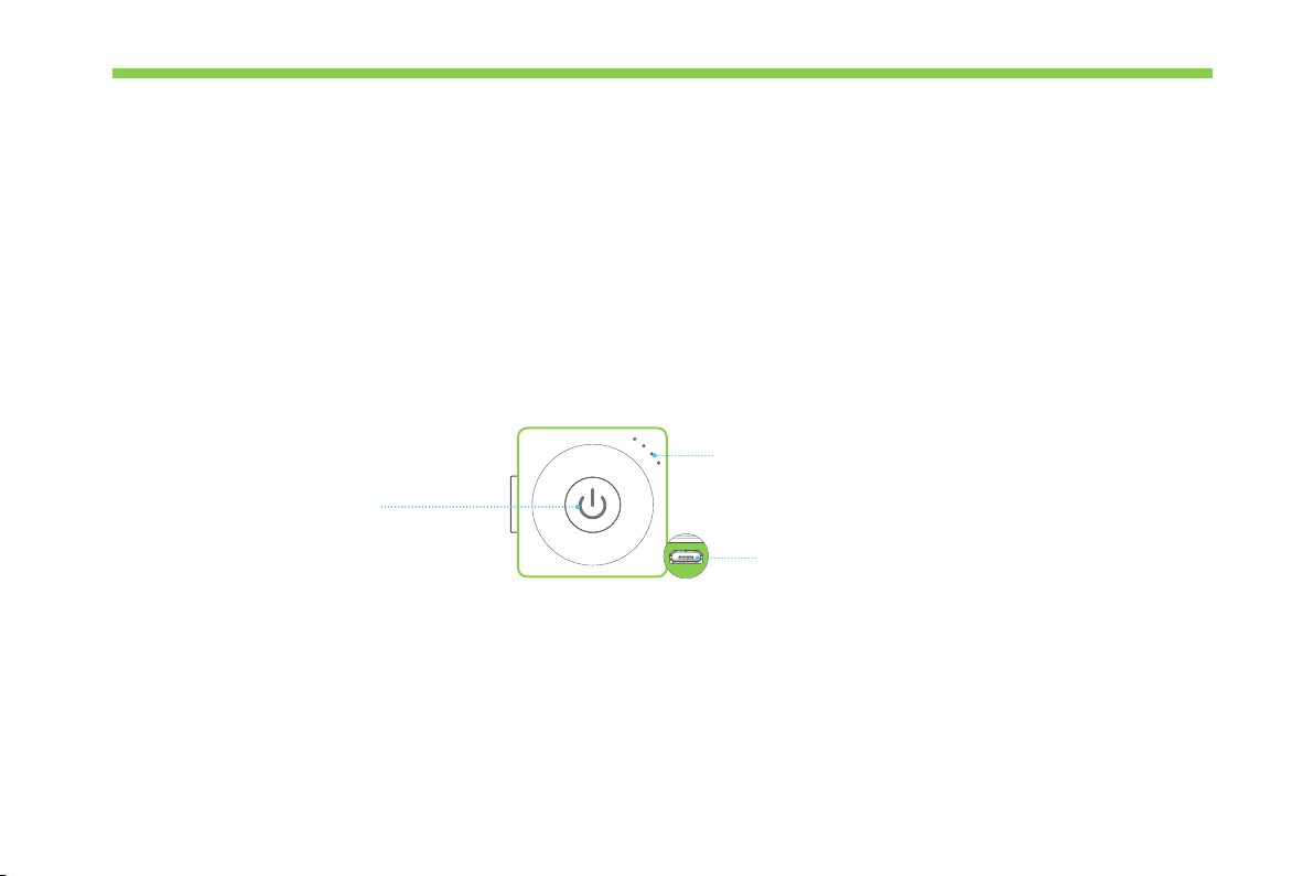
Power
Provide power to other blocks.
Appearance
Power Indicator
Press the Power button to
Power Button
Press to turn on. Press and hold
for about 3 seconds until all
LEDs go out to turn o.
r
P
e
o
w
Charge your power block
We recommend you to charge your power block when the last indicator is blinking.
display the current battery level.
Micro USB interface
To charge the power block.
09
Page 13
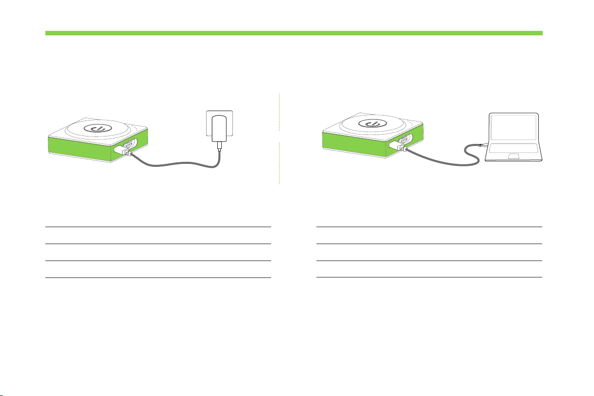
Specications
Via computerVia power adapter
or
Battery Capacity
Output Voltage
Input Voltage
Tips: 1. Please charge the block once every three months when not in use.
2. The power block cannot power the other blocks while it is charging.
950mAh
DC 5V
DC 5V
10
Input Current
Operating Temperature
Storage Temperature
< 1A
0° C ~ 45° C
-10° C ~ 55° C
Page 14
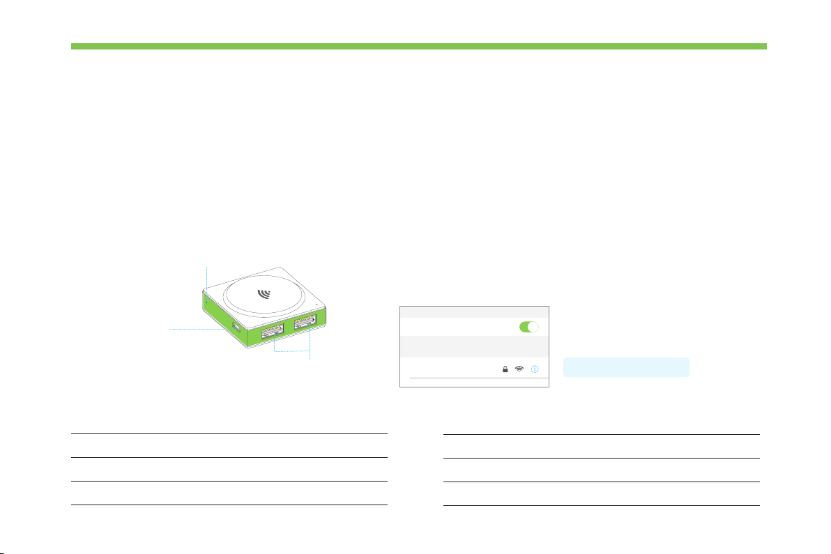
Wi-Fi
The Wi-Fi block has three functions:
·Establish a wireless connection between the blocks and your mobile device, then you can program the blocks via Makeblock Neuron app.
·Connect to your router to use more features, like IoT(Internet of Things).
·Provide power to other blocks. It contains a Micro USB interface, you can connect the block to power bank or power adapter via USB
cable to power the other blocks.
Appearance How to use?
Connect your tablet or smart phone to the Wi-Fi block by using the
Reset Button
network name (neuron-xxxxxx) and wireless password (makeblock).
Then launch the Makeblock Neuron app and follow the instructions on
the screen to use the Wi-Fi block.
Micro USB interface
Connect to camera block or Mic & Speaker block
Specications
Wireless Standards
Communication Distance
Working Mode
USB interface
IEEE 802.11b/g/n(HT20)
10m (Open environment)
STA/AP/STA+AP
Wi-Fi
CHOOSE A NETWORK...
neuron-xxxxxx
Operating Voltage
Operating Current
Operation Temperature
Password: makeblock
DC 5V
200mA
0° C ~ 45° C
11
Page 15
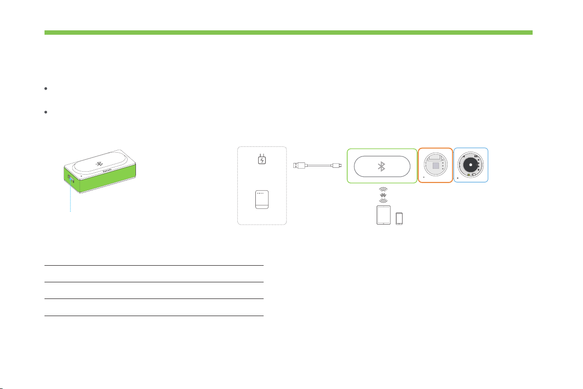
Bluetooth
Tablet Smart Phone
The Bluetooth block has two functions:
Establish a wireless connection between the blocks and your mobile device within 10 meters, then you can program the blocks via
Makeblock Neuron app.
Provide power to other blocks. It contains a Micro USB interface, you can connect the block to power bank or power adapter via USB
cable to power the other blocks.
Micro USB interface
Specications
Bluetooth Specication
Frequency Band
Output Power Class
12
BT 4.0
2402 ~ 2480MHz
≤ 4dBm
Power Adapter
(5V / 2A)
Power Bank
USB Cable
Bluetooth
r
G
o
y
s
r
n
B
o
e
S
r
u
e
z
z
Page 16
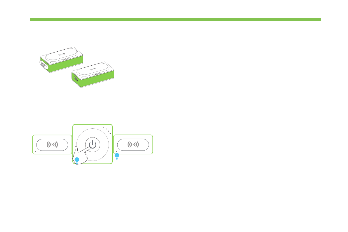
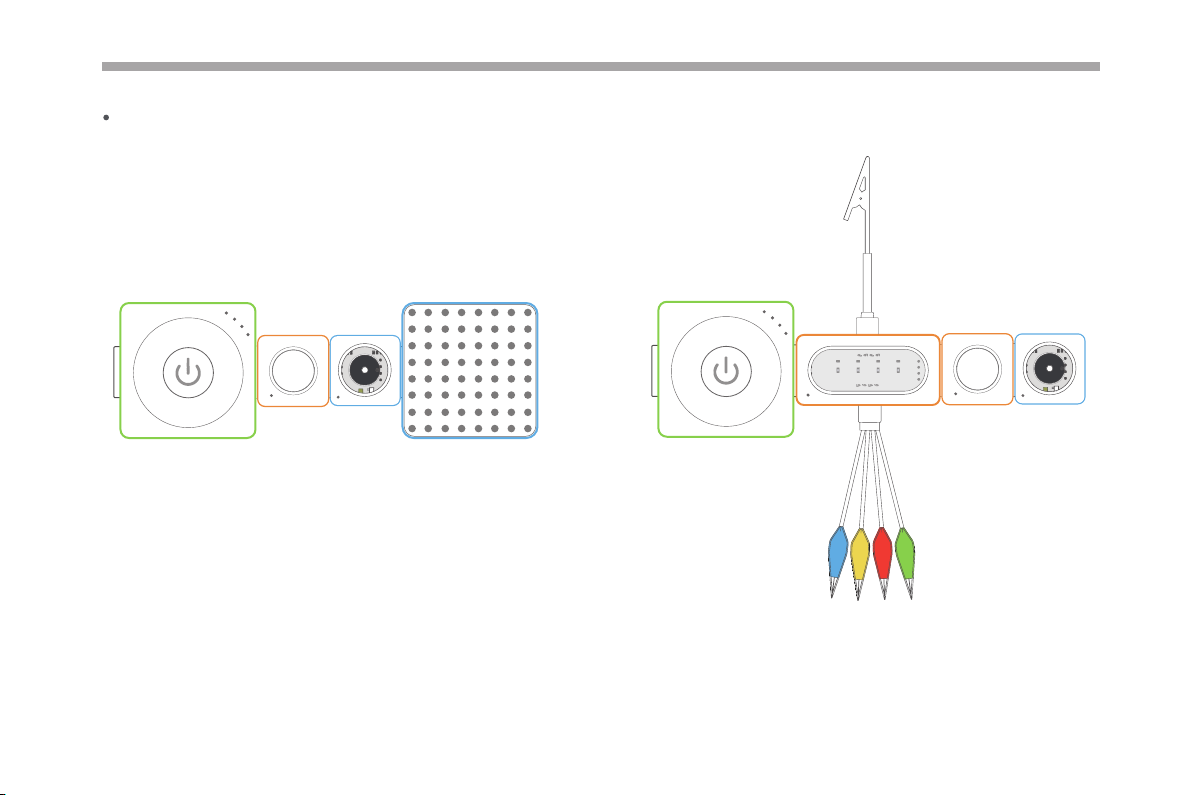
Wireless Transmitter + Wireless Receiver
Wireless receiver (Wireless-R) receives signals from wireless transmitter (Wireless-T)
within 10 meters. With these two blocks, you can establish a wireless connection
between two chains.
You may need to pair the two blocks before using: connect the two blocks to the power block as shown in the gure below.
Wireless R
1
Press
Wireless T
2
r
P
e
o
w
Watch the two indicators change from
blinking to solid on, indicating that the
pairing is successful.
13
Page 17

Try it now!
Press the button. Watch the RGB LED turn on.
3
4
14
1
Press
B
n
u
o
t
t
r
P
e
o
w
Wireless T
Wireless R
r
P
e
o
w
R
D
G
E
B
L
2
Transmitting chain Receiving chain
Press
Page 18

Input Blocks
Joystick
Try it now!
1
Press
k
c
i
t
s
y
o
J
Push the joystick to control your creation (such as a remote control car ) moving in the X-axis
(left-right) or Y-axis (up-down) direction.
Push the joystick.
2
J
k
o
c
i
y
t
s
r
P
e
o
w
Display
3
Read the X and Y values on the display block.
X stands for the displacement of the joystick on the X-axis, Y stands for the
displacement on the Y-axis.
15
Page 19

Button
16
n
o
t
t
u
B
Short press to turn something on and release to turn it o.
Press and hold for 5 seconds to stay in an active state.
Try it now!
Press and immediately
release the button.
2
3
B
n
u
o
t
1
r
P
e
o
w
t
Press
Press and hold the button block for 5 seconds, see what happens.
Watch the LED panel light up once.
Page 20

Knob
Try it now!
1
Press
b
o
n
K
Turn the knob clockwise.
2
K
n
b
o
r
P
e
o
w
The knob is an input block that can adjust the numerical value. After connect it to the output block,
you can turn the knob to adjust the output eect.
3
R
D
G
E
B
L
Watch the RGB LED light up and
get brighter gradually.
17
Page 21

Funny Touch
F
u
n
Funny Touch
Funny touch can be connected to any conductive object (such as bananas and water) and turn it into a touch switch. A simple and
interesting interactive eect can be achieved by detecting the conducting state between funny switches and GND wire.
GND wire
Touch
Funny
y
n
n
u
F
Indicators
Slot number
Four funny switches
How to use?
1. Plug the funny switch to slot 1 and the GND wire to slot 2.
2. Clip a funny switch to a conductive object.
3. Hold the metal clip of the GND wire and touch the conductive object with the other hand, the relevant indicator will light up and the
block will send out an on signal.
Tips: Alligator clip is sharp, please do not clip yourself with the funny switch or the clip of GND wire, it may hurt you.
18
Page 22

Try it now!
D
GN
Funny Touch
1
r
P
e
o
w
Funny
4
Watch the LED panel light up.
Press
2
Clip a funny switch to a banana. You can try other objects at
your home to see if they are conductive.
3
Touch both the metal part of the GND wire and the
banana with your hands.
Try touching another funny switch or touching two funny switches simultaneously, see what happens.
19
Page 23

Light Sensor
20
Try it now!
1
Press
r
o
s
n
e
S
t
h
g
i
L
Cover the light sensor.
r
P
e
o
w
The light sensor can detect the light intensity of the surrounding area.
The more light it receives, the stronger signal it sends out.
2
L
3
r
i
o
g
h
t
S
R
s
n
e
D
G
E
B
L
23
Display
The value ranges from 0 to 100.
The larger the value, the stronger the light intensity.
Watch the RGB LED darken and the light intensity
value on the display block become smaller.
Page 24

Dual IR Detector
Det
IR
l
a
u
D
Try it now!
Cover the IR detector with your nger.
Dual IR detector block can be used to make your creation follow a black line on a white
ector
background or a white line on a black background. It contains two IR detectors which can be
used to control the output.
Detecting Range:0 ~ 2cm
2
1
Press
3
Dual IR Detector
r
P
e
o
w
Watch the LEDs on the left half of the LED panel
light up.
21
Page 25

Ultrasonic Sensor
22
Try it now!
1
Press
r
o
ns
Se
onic
ras
t
Ul
Ultrasonic sensor can be used to measure distance
between the block and the obstacle, from 3cm to 300cm.
Put your hand right above
the ultrasonic sensor.
2
200.2cm
3
Ultrasonic Sensor
r
P
e
o
w
Display
Read the distance value on the display block.
Page 26

Color Sensor
Try it now!
r
o
s
n
e
S
r
o
l
o
C
The color sensor can detect dierent colors.
Cover the color sensor with
dierent colored objects.
2
1
P
o
w
Press
Gyro Sensor
r
3
C
o
o
s
l
n
o
e
r
S
r
e
r
o
s
n
e
S
o
r
y
G
The gyro sensor is an ideal block for motion and posture detection of your creation.
It can be used to measure the angular value and the acceleration information of your
See what happens.
creation. When it detects a vibration, the sensor will send out an on signal.
23
Page 27

Reference coordinates: Detect a vibration:
Z-axis
Y-axis
24
X-axis
r
o
s
n
e
S
o
r
y
G
Try it now!
The buzzer will be activated when the
gyro sensor detects any vibration.
3
r
G
o
y
s
r
n
o
e
1
Press
S
r
P
e
o
w
B
r
u
e
z
z
2
Place the blocks on the desk and thump the desk.
Pick up the blocks and rotate it, see what happens.
Display
Send out an on signal
Pitch ( -180° ~ 180° ): The degree of rotation around the y-axis.
Roll ( -90° ~ 90° ): The degree of rotation around the x-axis.
Page 28

Temperature Sensor
Try it now!
1
Press
r
o
s
n
e
S
p
m
e
T
p
m
e
T
Get the temperature probe and plug it into the slot. The temperature sensor can detect
temperatures from -55℃ to 125℃ .
Accuracy: ±0.5° C ( -10° C ~ 85° C)
Tips: The cable of temperature probe may be damaged when the temperature is over 100℃ .
Please be careful to protect the cable from damage.
3
r
o
T
s
e
n
m
e
p
S
r
P
e
o
w
Temp
2
Display
Put the temperature probe into the water.
Read the temperature value on
the display block.
25
Page 29

Humiture Sensor
r
o
s
n
e
S
e
r
u
t
i
m
u
H
Specications
Humiture sensor can detect temperature and humidity of the surrounding area.
Temperature Range -40℃ ~ 125℃
Temperature Accuracy
Try it now!
Read the temperature and humidity values.
2
r
H
o
u
s
m
n
i
e
t
S
u
r
1
r
P
e
o
w
e
Display
Press
26
± 1℃
Temperature value
Humidity value
Humidity Range
0% ~ 100%
Humidity Accuracy ± 3%
Page 30

Soil Moisture Sensor
Try it now!
1
Press
e
r
u
t
s
i
o
M
l
i
o
S
Get the soil moisture probe and plug it into the slot.
The soil moisture sensor can detect soil humidity.
il
o
S
59%
e
S
r
o
u
i
t
l
s
i
M
o
r
P
e
o
w
Soil
Display
2
The value ranges from 0 to 100%. The larger the value,
the higher the humidity.
Insert the probe into the soil, read the
humidity value on the display block.
27
Page 31

Sound Sensor
28
Try it now!
1
Press
r
o
s
n
e
S
d
n
u
o
S
The sound sensor can detect the sound intensity of the surrounding area.
The louder sound it receives, the stronger signal it sends out.
Watch the RGB LED light up and read the sound
intensity value on the display block.
3
r
S
o
s
o
u
n
d
r
P
e
o
w
R
n
e
S
2
D
G
E
B
L
Display
Make a sound near the sensor.
The value ranges from 0 to 100. The larger the
value, the stronger the sound intensity.
Page 32

PIR Sensor
PIR sensor (Passive Infrared sensor) can detect motion from humans within 3 meters. If anyone moves in that range, the sensor will
send out an on signal to the following block.
Try it now!
1
Press
r
o
s
n
e
S
R
I
P
When powered on, the indicator will light up and it will take about 5 seconds for the block to initialize.
Once successfully initialized, the indicator will go out.
The buzzer will make a buzzing sound and the PIR
block will light up for 5 seconds.
3
r
o
P
s
I
n
B
R
e
S
r
P
e
o
w
r
u
e
z
z
2
Display
After the PIR initializes successfully,
Wave your hand near the sensor.
29
Page 33

Camera
a
r
e
m
a
C
How to use?
Connect the block to Wi-Fi block via USB cable and control the block through Makeblock Neuron app.
C
a
a
r
m
e
The camera block allows you to take pictures.
Specications
Resolution
Pixel Size
Max Image Transfer Rate
Power Consumption
Power Supply
Optical FOV
30
USB Cable
r
W
i
F
i
-
P
e
o
w
1280×720
3.4um×3.4um
Full size @ 30fps
100uA (Standby)~240mW (Active)
USB Bus Power
100°
Tablet Smart Phone
Temperature Range
Lens Construction
F/No
Eective Focal Length (EFL)
Operating:-30℃ ~ 70℃
Stable Image:0℃ ~ 50℃
4G+IR
2.97
2.4mm
Page 34

Output Blocks
Dual Servo Driver
Servo Driver
Slot number
Servo
Servo Driver
S
Servo Specications
Storage Temperature
Operating Temperature
Operating Voltage
Excessive Play
The servo driver can drive two servos simultaneously.
The servo can rotate from 0 to 180 degrees.
o
v
r
e
Plug the servo into the servo driver.
-20℃ ~ 60℃
-10℃ ~ 50℃
4.5V ~ 6.0V
Idle Current (at stopped)
Stall Torque (at locked)
Limit Angle
6±1mA
1.5±0.05 kg·cm
180° ± 10°
≤ 1°
31
Page 35

Servo Accessory Pack
The servo accessory pack contains three dierent servo hubs to meet your needs. The servo
hub is designed to attach objects to the servo.
How to use?
1. Connect the servo hub to the servo by pressing or using a screw (more permanent).
r
ive
rvo Dr
e
r
ive
rvo Dr
e
S
o
v
r
e
S
2. Attach objects to the hub.
or
S
o
v
r
e
S
M2.2×6.5mm Self-drilling Screw
Tips: Please use a phillips screwdriver
(not included in the package) to tighten
the screw.
32
Page 36

Try it now!
1
r
P
e
o
w
Place the blocks on the
desk and press the button.
Servo Bracket
180°
r
G
o
y
s
r
n
o
e
S
Servo Driver
Servo
0°
3
Watch the servo and see what happens.
2
Thump the desk with your hands.
The servo bracket can be used to connect servo to the Neuron board or LEGO® blocks.
33
Page 37

Connect servo to the Neuron board:
Dual DC Motor Driver
r
Drive
r
o
DC Mot
Slot number
The DC (Direct Current) motor driver can drive DC motor or water pump, two devices can be driven
simultaneously.
34
Page 38

DC Motor
r
e
iv
r
D
r
o
Mot
DC
Motor
Output shaft
Connect DC motor to the Neuron board:
The DC (Direct Current) motor contains an output shaft. The shaft will rotate
when the DC motor driver accept an on signal.
Motor Specications
Rated Speed
Rated Current
Rated Torque
Stall Torque
Stall Current
Gear Ration
118±10% RPM
0.1 A
132 g. cm
590±100 g.cm
0.4 A
1:100
35
Page 39

Wheel Hub
Made of plastic and can be used as a car's wheel.
Tyre
Tyre covers the wheel to protect it and provide traction between the wheel and the road.
Attach the wheel to the motor:
36
Page 40

Crossed Shaft Connector
Works with DC motor, mechanical parts of Makeblock platform,
LEGO® blocks and other materials to the DC motor.
Mini Auxiliary Wheel
Mini auxiliary wheel is compatible with LEGO® blocks, and can be used in light-load car body,
making 360 degree movement easily.
Connect mini auxiliary wheel to the Neuron board:
37
Page 41

Water Pump
The water pump can be used for water priming pump,
Water
Pump
Follow the gure below to install the water pump.
r
Drive
r
o
DC Mot
Water
Pump
automotive pump and so on.
water
inlet
Tips: Please cut the rubber
hose according to your needs.
water
outlet
Water pump Specications
Rated Voltage
Current (With load)
Operating Temperature
Operating Humidity
Water Hole Diameter
Noise
DC 12V
< 320mA
-10℃ ~ 55℃
< 95%
6.5mm
< 60dB
38
Page 42

RGB LED
The RGB LED can emit various colors of light. Change the color or brightness of the RGB LED
D
E
L
B
G
R
through Makeblock Neuron app or mBlock.
Tips: RGB is an additive color model in which red, green, and blue light are combined in
various ways to reproduce a broad array of colors.
LED Strip Driver + LED Strip
p
i
r
t
S
D
E
L
D
E
L
Get the LED strip and plug it into the slot. The LED strip contains 15 RGB LEDs. Change the
color of each LED and do more interesting things through Makeblock Neuron app or mBlock.
Try it now! A special use case for LED strip.
Push the joystick to the up.
2
p
i
L
r
E
J
k
o
c
i
y
t
s
r
P
1
e
o
w
t
D
S
LED
3
Press
Push the joystick to the down, left or right, see what happens.
Watch the LEDs light
up one by one.
39
Page 43

LED Panel
EL Wire Driver + EL Wire
The LED panel contains 64 RGB LEDs. Change the color and do more interesting things through
Makeblock Neuron app or mBlock.
EL Wire Driver
Attentions:
1. Do not turn on the driver before you plug the EL wires into the slots.
2. Do not bend the EL wire in acute angle.
3. Do not pull out or insert the EL wire when the driver is powered on.
4. Do not drag the wire when pulling out or inserting the EL wire.
Get the EL wire (Electroluminescent wire) and plug it into the slot.
The EL wire driver can drive 4 EL wires simultaneously.
40
Page 44

Mic & Speaker
Play a sound or speak into to record your voice.
Microphone
Previous track
Record button
Play / Pause
Next track
SpeakerMicro USB interface
How to use?
Connect the block to Wi-Fi block via USB cable, then control the block via Makeblock Neuron app.
Tablet Smart Phone
USB Cable
r
W
i
F
i
-
P
e
o
w
41
Page 45

Buzzer
42
Display
r
e
z
z
u
B
The buzzer makes a buzzing sound when it receives an on signal. You can program the buzzer to
get a dierent sound by using Makeblock Neuron app or mBlock.
lay
p
Dis
Display the output parameters of the block in front of display block. Customize the display
content via Makeblock Neuron app or mBlock.
Page 46

Accessories
Laser Pointer
The laser pointer emits a coherent laser beam.
Press to emit laser beam.
Charge your laser pointer
Via power adapter Via computer
or
Specications
Battery Capacity
Battery Life
Laser Transmit Power
85mAh
≥ 10h
1mW
43
Page 47

Try it now!
1. Press the power button to turn on the chain.
2. Press the button on the laser pointer and focus the laser beam on the light sensor.
The buzzer will make a buzzing sound.
Neuron Board
1. Snap Neuron blocks to the mechanical parts of Makeblock.
2. Snap Neuron blocks to LEGO blocks.
How to use?
Connect two Neuron boards:
Snap the blocks to the Neuron boards:
r
o
s
n
e
S
o
r
y
G
h
ot
o
t
lue
B
L
r
i
o
B
g
h
n
t
e
S
r
P
e
o
w
r
e
z
z
u
B
r
s
u
e
z
z
44
Page 48

Rubber Bands
Used to fasten the servo to the Neuron boards.
r
e
v
i
r
D
o
v
r
Se
Servo
Magnet Wire
Provide a more exible way to connect blocks, available with 10cm and 20cm.
45
Page 49

USB Cable
Gel Pad
1. Connect some specied blocks, such as camera, Mic & Speaker, Bluetooth, Wi-Fi.
2. Provide power and transmit the data.
46
Fixed Clip
Gel Pad
Gel pad can rmly paste the blocks to any surface and can be reused.
The xed clip can be used for motor cable storage.
Page 50

FAQ
Q: Why the program stops running after exiting the Makeblock Neuron app?
A: The Bluetooth block can not store programs, thus it needs the app to run the program.
Q: What should I do if the blocks have no response?
A: Reasons that may cause the problem:
When not using the Makeblock Neuron app or mBlock, the input block must be connected on the left of the ouput block. Please
refer to the Easy Connection section to check if the connection is correct.
The Neuron rmware upgrade process is interrupted (due to poor connection). Please try to upgrade rmware again.
The silicone case of the block was installed improperly, which may cause poor connectivity. Please adjust the silicone case
positions accordingly.
Q: Why does the battery life decrease?
A: The Power block uses a lithium-ion battery, multiple charges and discharges may decrease the battery life gradually.
Q: Why does the funny touch block goes wrong?
A: Reasons that may cause the problem:
The power supply is unstable. Please use a power adapter or power bank of high quality.
Mistakenly plug the funny switch to slot 2 and the GND wire to slot 1, please replug them to the correct slots.
If the funny touch goes wrong when working with EL wire driver, please try to connect the two blocks to both sides of power block.
47
Page 51

Q: What should I do if my tablet or phone cannot connect to the Wi-Fi block?
When turned on, the Wi-Fi block will boot for a while. Please wait and refresh the Wi-Fi list on your device.
Reset the Wi-Fi block and try again. While the Wi-Fi block is powered on, use a pin to press and hold the Reset button until the
indicator goes out, then release the button, the Wi-Fi block will restore and reboot automatically.
Q: What should I do if the Wi-Fi block cannot connect to my home network?
The network name or password is wrong, please re-enter the name and password.
The network signal is too weak. Please close the Wi-Fi block to your router and try again.
Special authentication is required when connecting to a public network. Please try to connect to another network with network
name and password.
Find more FAQs, please visit http://neuron.makeblock.com/faq
48
Page 52

FCC STATEMENT:
This device complies with Part 15 of the FCC Rules. Operation is subject to the following two conditions:
(1) This device may not cause harmful interference, and
(2) This device must accept any interference received, including interference that may cause undesired operation.
Warning: Changes or modications not expressly approved by the party responsible for compliance could void the user's authority to
operate the equipment.
NOTE: This equipment has been tested and found to comply with the limits for a Class B digital device, pursuant to Part 15 of the
FCC Rules. These limits are designed to provide reasonable protection against harmful interference in a residential installation. This
equipment generates uses and can radiate radio frequency energy and, if not installed and used in accordance with the instructions,
may cause harmful interference to radio communications. However, there is no guarantee that interference will not occur in a
particular installation. If this equipment does cause harmful interference to radio or television reception, which can be determined by
turning the equipment o and on, the user is encouraged to try to correct the interference by one or more of the following measures:
Reorient or relocate the receiving antenna.
Increase the separation between the equipment and receiver.
Connect the equipment into an outlet on a circuit dierent from that to which the receiver is connected.
Consult the dealer or an experienced radio/TV technician for help.
RF warning statement:
The device has been evaluated to meet general RF exposure requirement. The device can be used in portable exposure condition
without restriction.
IC STATEMENT:
This device complies with Industry Canada licence-exempt RSS standard(s). Operation is subject to the following two conditions:
49
Page 53

(1) this device may not cause interference, and
(2) this device must accept any interference, including interference that may cause undesired operation of the device."
Le présent appareil est conforme aux CNR d'Industrie Canada applicables aux appareils radio exempts de licence. L'exploitation est
autorisée aux deux conditions suivantes :
(1) l'appareil nedoit pas produire de brouillage, et
(2) l'utilisateur de l'appareil doit accepter tout brouillage radioélectrique subi, même si le brouillage est susceptible d'en compromettre
le fonctionnement."
DECLARATION OF CONFORMITY
Declaration of conformity Hereby, Makeblock Co., Ltd., declares that this product is in compliance with the essential requirements and
other relevant provisions of Directive RED 2014/53/EU and the RoHS directive 2011/65/EU
50
Age
6+
WARNING:
CHOKING HAZARD
- Small parts. Not for children under 3 years.
Children to use only under adult's supervision.
 Loading...