

Page 1
1
PREPAR3D GUIDE
MAJESTIC SOFTWARE’S
BOMBARDIER Q400 “DASH 8”
BY CHUCK
LAST UPDATED: 06/03/2018
Page 2
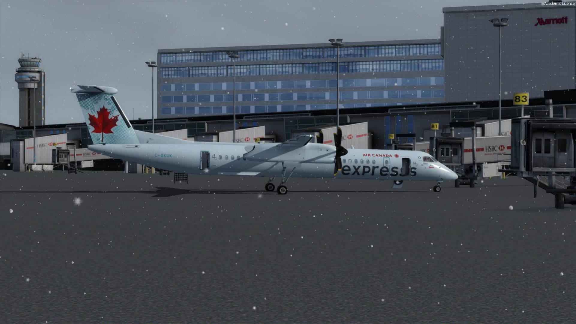
TABLE OF CONTENT
• PART 1 – INTRODUCTION
• PART 2 – COCKPIT LAYOUT
• PART 3 – FLIGHT PLANNING
• PART 4 – START-UP PROCEDURE
• PART 5 – TAXI
• PART 6 – TAKEOFF, CLIMB & CRUISE
• PART 7 – AUTOPILOT
• PART 8 – ENGINES & HYDRAULICS
• PART 9 – ICE PROTECTION
• PART 10 – APPROACH & LANDING
2
MAJESTIC Q400 EDITION: PRO
PLATFORM: PREPAR3D V 4.1
Page 3
3
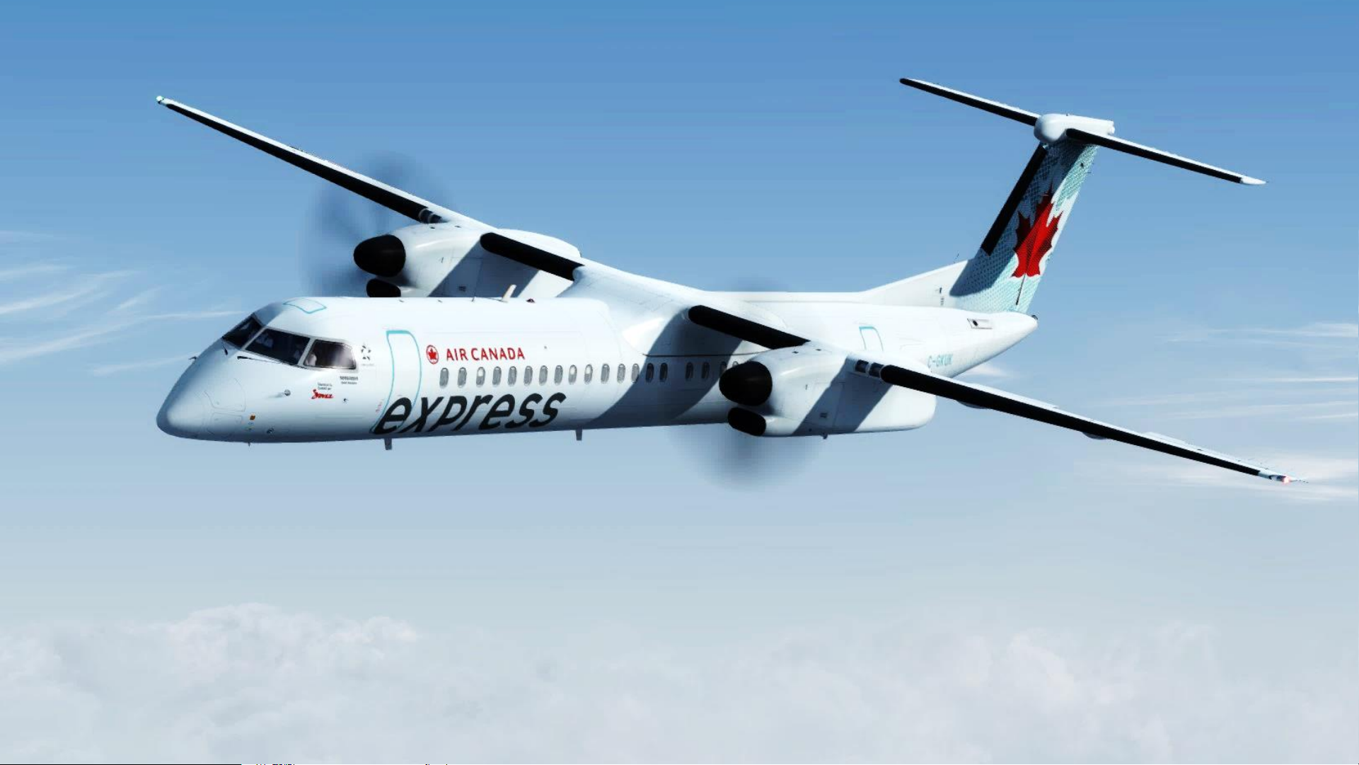
The Dash 8 “Q400” is a series of twin-engine, medium-range, turboprop regional airliners. The
aircraft was introduced by de Havilland Canada (DHC) in 1984. Originally named the DHC-8
(nicknamed “Dash 8”), the aircraft started as the -100 series, then the -200 series, the -300
series and finally the -400 series. They are now produced by Bombardier Aerospace. De
Havilland Canada was sold to Boeing in 1986, but then re-sold to Montreal-based Bombardier
Aerospace in 1992. This acquisition was done in the midst of Bombardier’s expansion of the late
80’s; it had acquired Canadair in 1986, Short Brothers in 1989 and then Learjet as well in 1990.
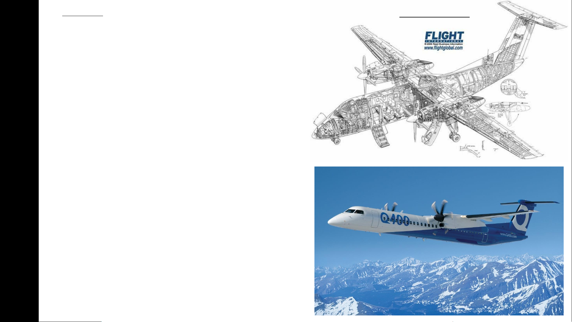
The Dash 8 was developed from the de Havilland Canada Dash 7, which featured extreme short
take-off and landing (STOL) performance. With the Dash 8, DHC focused on improving cruise
performance and lowering operational costs. The engine chosen was the Pratt & Whitney
Canada PW100. The aircraft has been delivered in four series. The Series 100 has a maximum
capacity of 39, the Series 200 has the same capacity but offers more powerful engines, the
Series 300 is a stretched, 50-seat version, and the Series 400 is further stretched to 78
passengers. Over 1,000 Dash 8s of all models have been built.
The DHC-8-400 “Q400” is a stretched and improved version of the Dash 8 that entered service
in 2000. It is equipped with an ANVS system (Active Noise and Vibration Suppression). Models
delivered after 1997 have cabin noise suppression and are designated with the prefix "Q“, as in
“Q400”. Its 360 knot (667 km/h) cruise speed is 60–90 knots (111–166 km/h) higher than its
competitors and predecessors. Powered by PW150A engines rated at 5,071 shp (3,781 kW) at
maximum power (4,850 shp or 3,620 kW maximum continuous rated). The maximum operating
altitude is 25,000 ft (7,600 m) for the standard version. Production of the Series 100 ceased in
2005, and the Q200 and Q300 in 2009.
The Q400 has been through two company acquisitions, one of which was near fatal. The
engineers who worked on this airframe are very proud of its rich history and know all too well
the challenges of stretching the airframe and stretching a shrinking budget. We have to
remember that this started as a bush flying aircraft that has been marketed to compete with
jets. The aircraft is incredibly diverse being able to serve in high end commuter markets, to
military platforms and even as a water bomber. This is an aircraft that has adapted to changing
economic times and kept a great safety rating.
This is an aircraft designed to operate in the harsh canadian winter and difficult weather
conditions that you will have to fly into without expensive automation systems: there is no
auto-throttle nor auto-land system. The approaches need to be planned very carefully and most
of your landings will be quite “firm” because of the landing gear’s configuration. Give it a
chance and I am sure that you will enjoy its superbly simulated systems. Great job, Majestic
Software!
PART 1
–
INTRODUCTION
Dash 8-100 Cutaway
Page 4
4
PART 1
–
INTRODUCTION
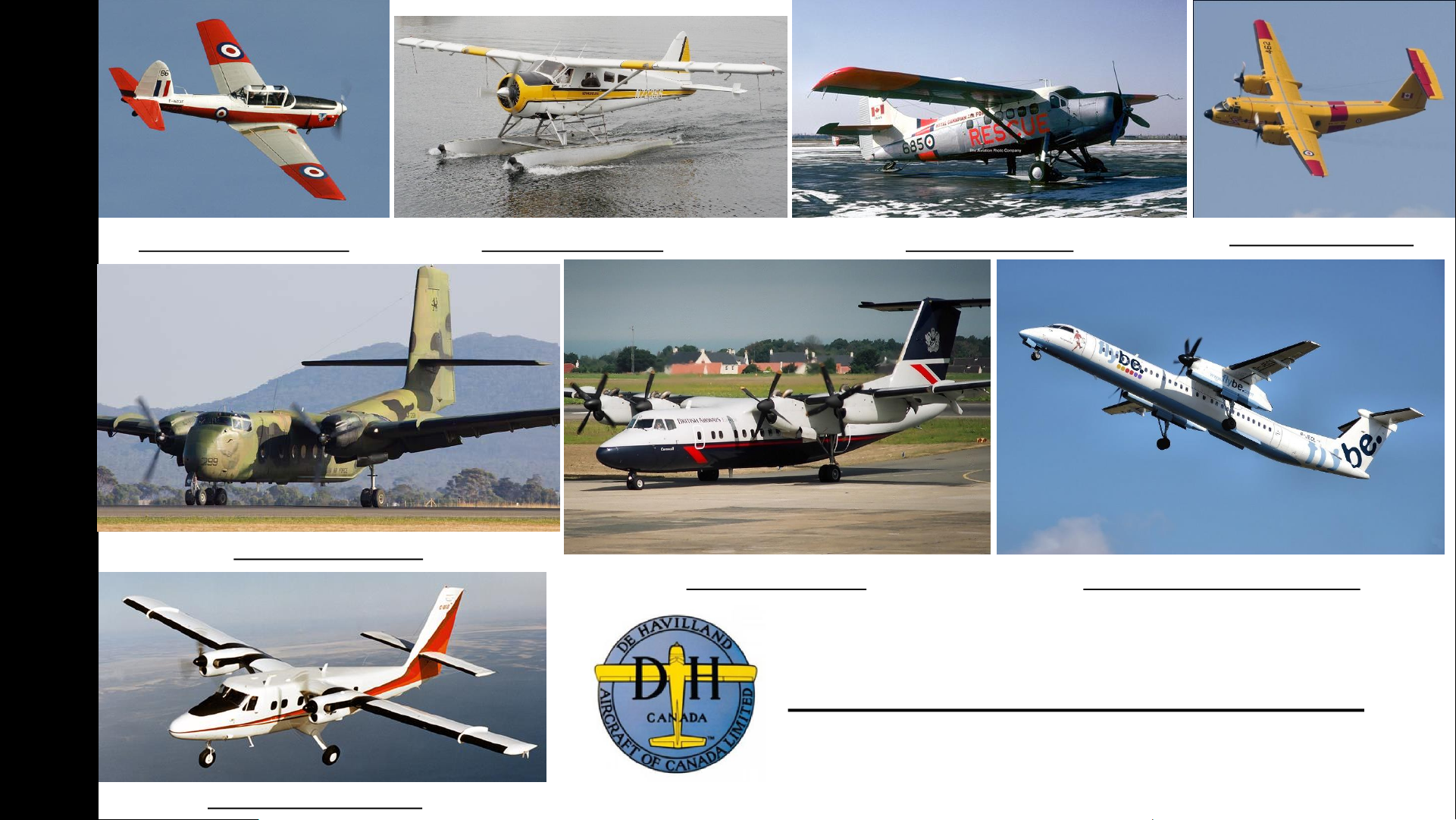
DHC-1 Chipmunk (1946) DHC-2 Beaver (1947) DHC-3 Otter (1951)
DHC-4 Caribou (1958)
DHC-5 Buffalo (1964)
DHC-6 Twin Otter (1965)
DHC-7 Dash 7 (1975) DHC-8 Dash 8 “Q-Series” (1983)
De Havilland Canada Aircraft
Page 5

5
Before you even step foot in your virtual cockpit, you need to know where you are, where you are going, how you will
get there, what you need to get there. This document is structured like a short tutorial flight.
The flight tutorial is structured as follows:
• Familiarize yourself with the cockpit layout
• Plan your flight
• Determine the flight route, fuel & cargo loads
• Spawn the aircraft and set it in a Cold & Dark state
• Provide aircraft with power
• Program the FMC (Flight Management Computer)
• Start–up the aircraft and make it ready for flight
• Taxi
• Takeoff
• Climb and cruise
• Explore autopilot capabilities
• Explain engine and hydraulic system functionalities
• Explain the ice protection systems
• Descend, approach and land
TUTORIAL STRUCTURE
PART 1
–
INTRODUCTION
Page 6

6
DISCLAIMER: Do not use this guide for real life flying. I mean it.
Majestic Software Downloads Section
http://majesticsoftware.com/mjc8q400/downloads.html
Smart Cockpit Dash-8-400
http://www.smartcockpit.com/plane/BOMBARDIER/DASH-8-400.html
Froogle Sims Q400 Fully Loaded Playlist (Youtube)
https://www.youtube.com/watch?v=PkOc2gIS_s8&list=PL_xDmvmUFDEjAyzamHQaoM7hXrJudErUX
Airline2Sim (Payware Course)
https://www.airline2sim.com/course/q400-cadet/
Airline2Sim SIDs and STAR (Youtube)
https://www.youtube.com/watch?v=CKhxjVHTJYc
Aircraft Icing:
https://aircrafticing.grc.nasa.gov/1_1_3_3.html
BEST RESOURCES
PART 1
–
INTRODUCTION
Page 7
7
PART 2
–
COCKPIT LAYOUT
Page 8
8
PART 2
–
COCKPIT LAYOUT
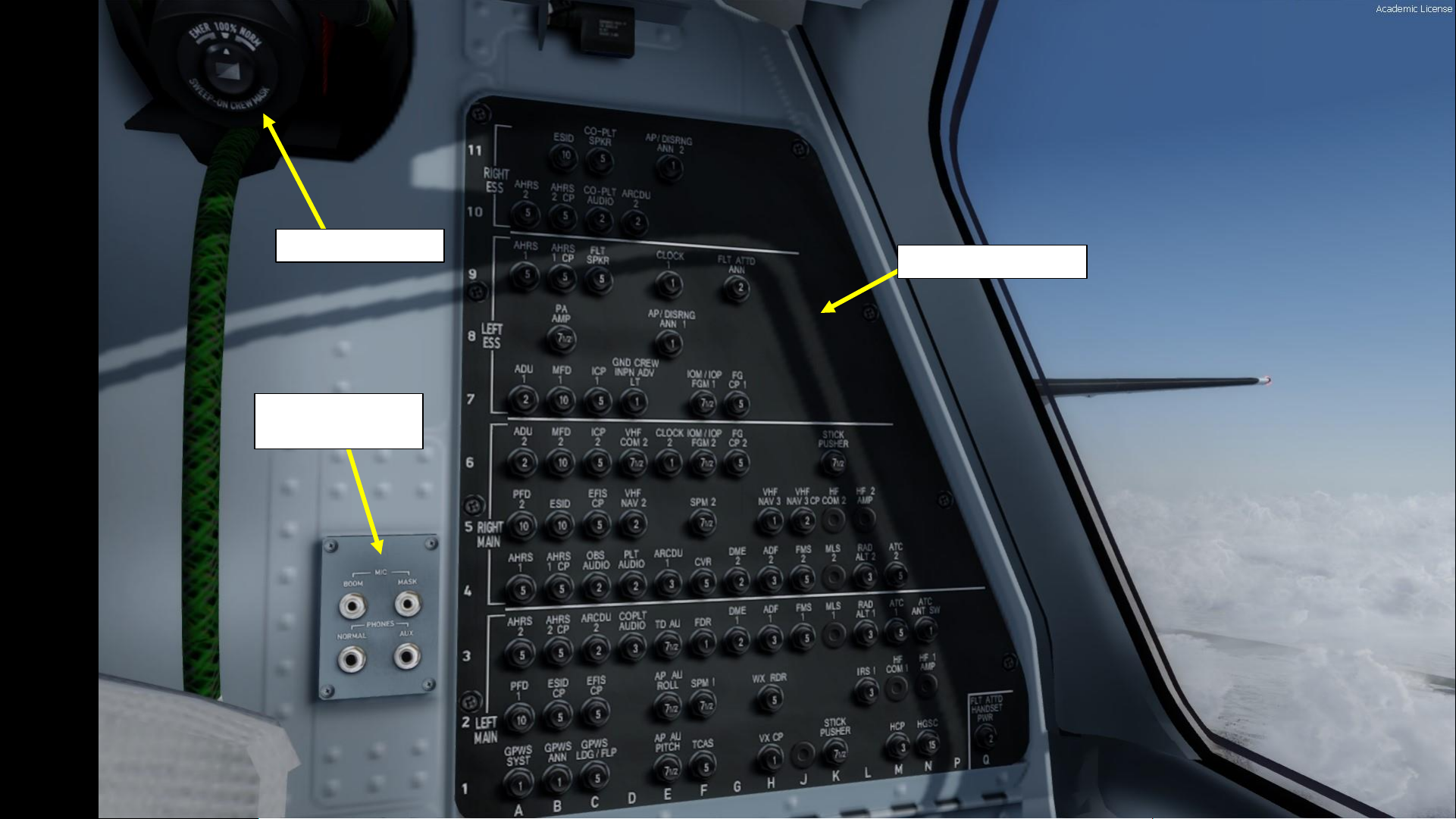
Circuit Breaker Panel
Microphone &
Headset Jacks
Oxygen Crew Mask
Page 9
9
PART 2
–
COCKPIT LAYOUT
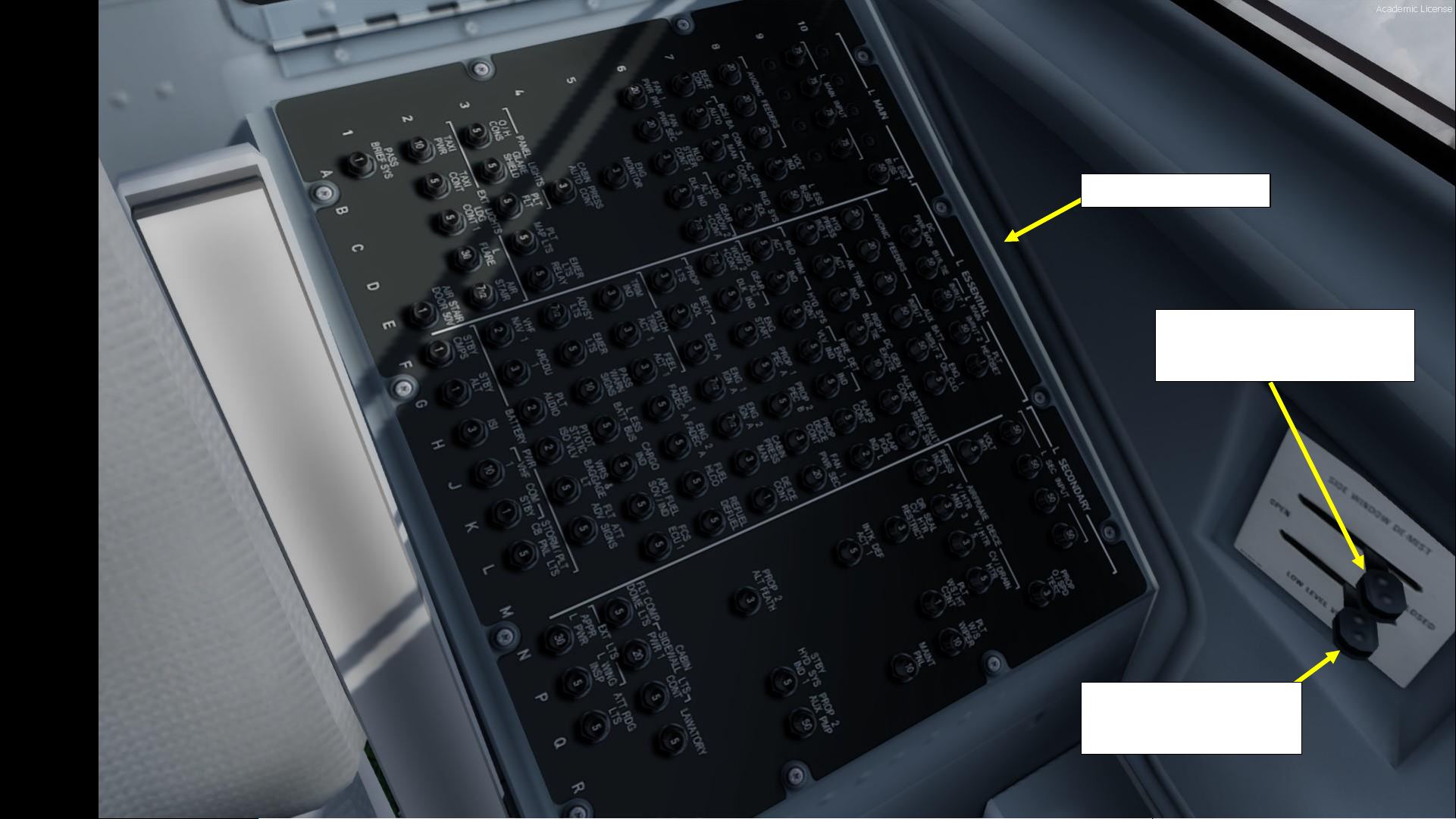
Circuit Breaker Panel
Side Window De-Mist Control
AFT = OPEN
FWD = CLOSED
Low Level Vents Control
AFT = OPEN
FWD = CLOSED
Page 10
10
PART 2
–
COCKPIT LAYOUT
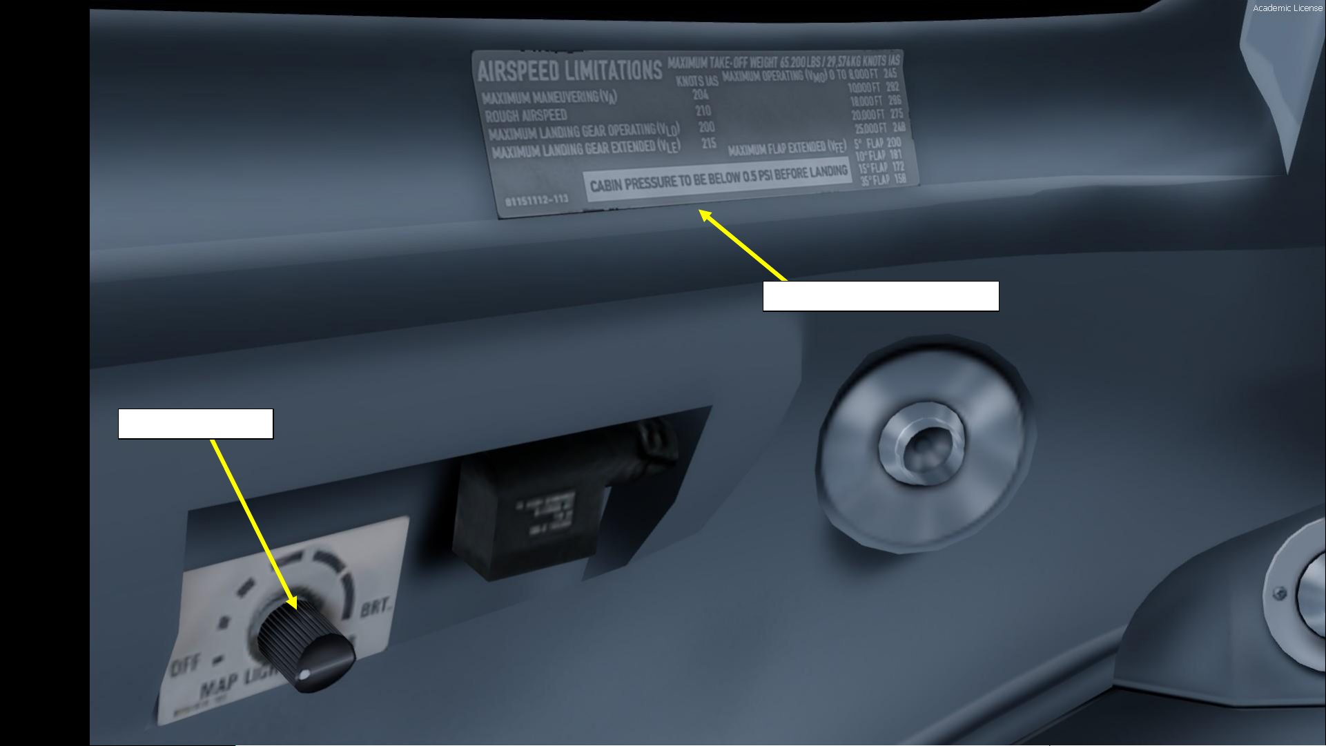
Map Light Control
Airspeed Limitations Placard
Page 11
11
PART 2
–
COCKPIT LAYOUT
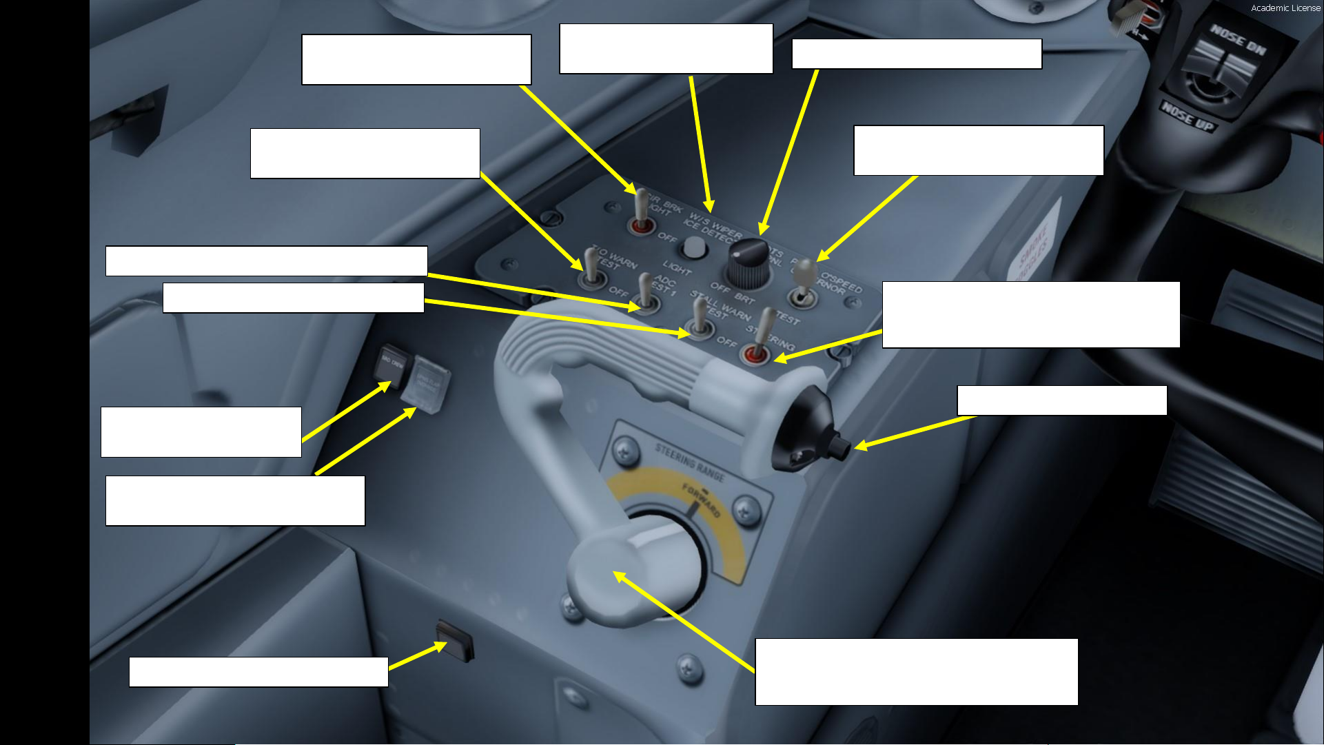
GPWS (Ground Proximity Warning
System) Flap Override Button
Ground Crew Connection
Annunciator
Steering Hand Control (Tiller)
Used to steer aircraft on ground. Left click and drag
to steer.
Push-To -Talk (PTT) Switch
Circuit Breaker Panel Lighting
Control Toggle Switch
Windshield Wiper Ice
Detection Light Pushbutton
Pilot’s Side Panel Dimmer Knob
Propeller Overspeed Governor
Test Toggle Switch
Nosewheel Steering Toggle Switch
AFT = OFF
FWD = NOSEWHEEL STEERING ON
Takeoff Warning System Test
Toggle Switch
ADC (Air Data Computer) Test Toggle Switch
Stall Warning Test Toggle Switch
Alternate Pilot Wiper Pushbutton
Page 12
12
PART 2
–
COCKPIT LAYOUT
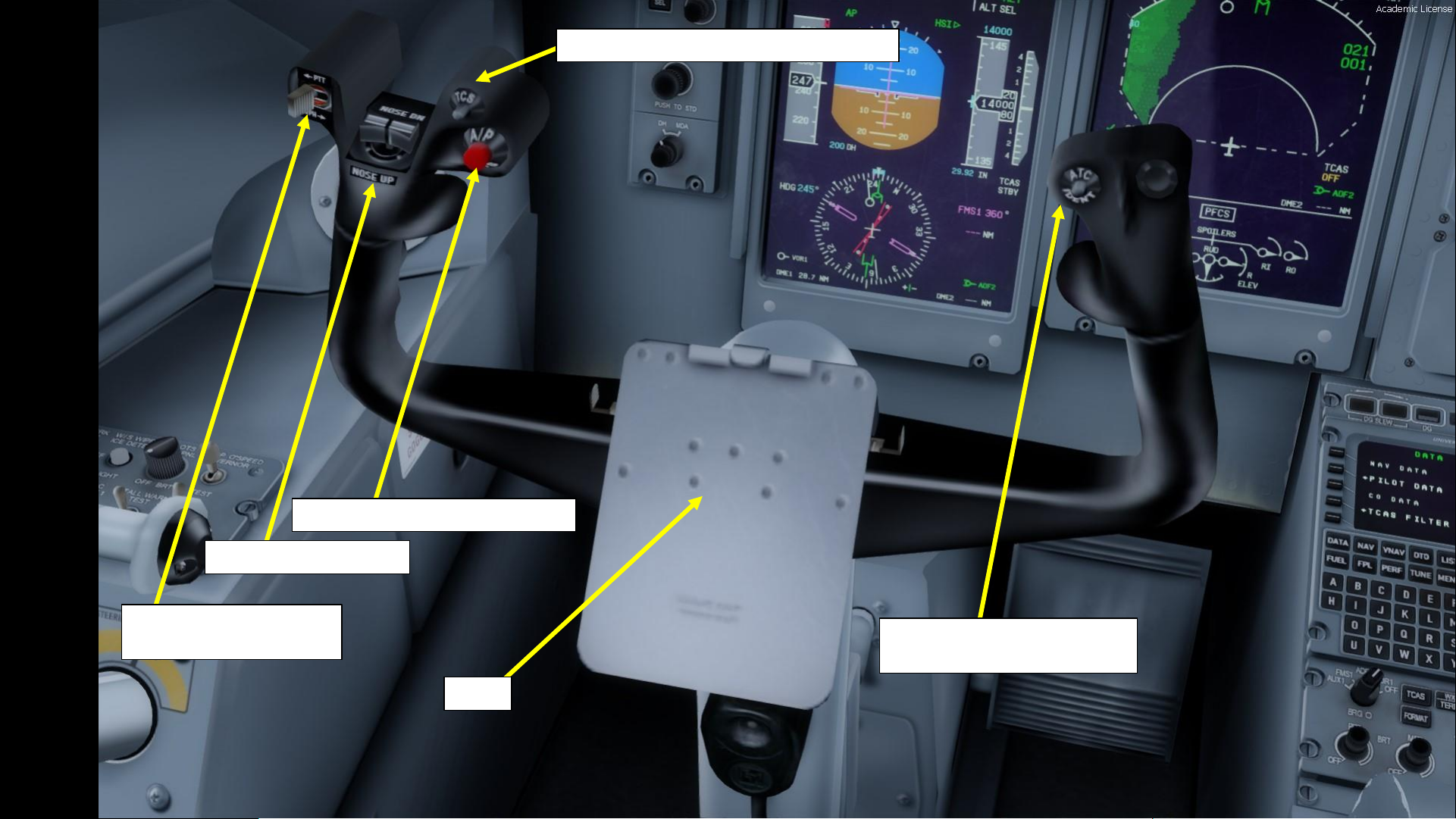
Transmit/Interphone
Push-to-Talk Switch
Elevator Trim Switches
Autopilot Disengage Pushbutton
Yoke
TCS (Tactile Control Steering) Pushbutton
ATC (Air Traffic Controller)
Identification Pushbutton
Page 13
13
PART 2
–
COCKPIT LAYOUT
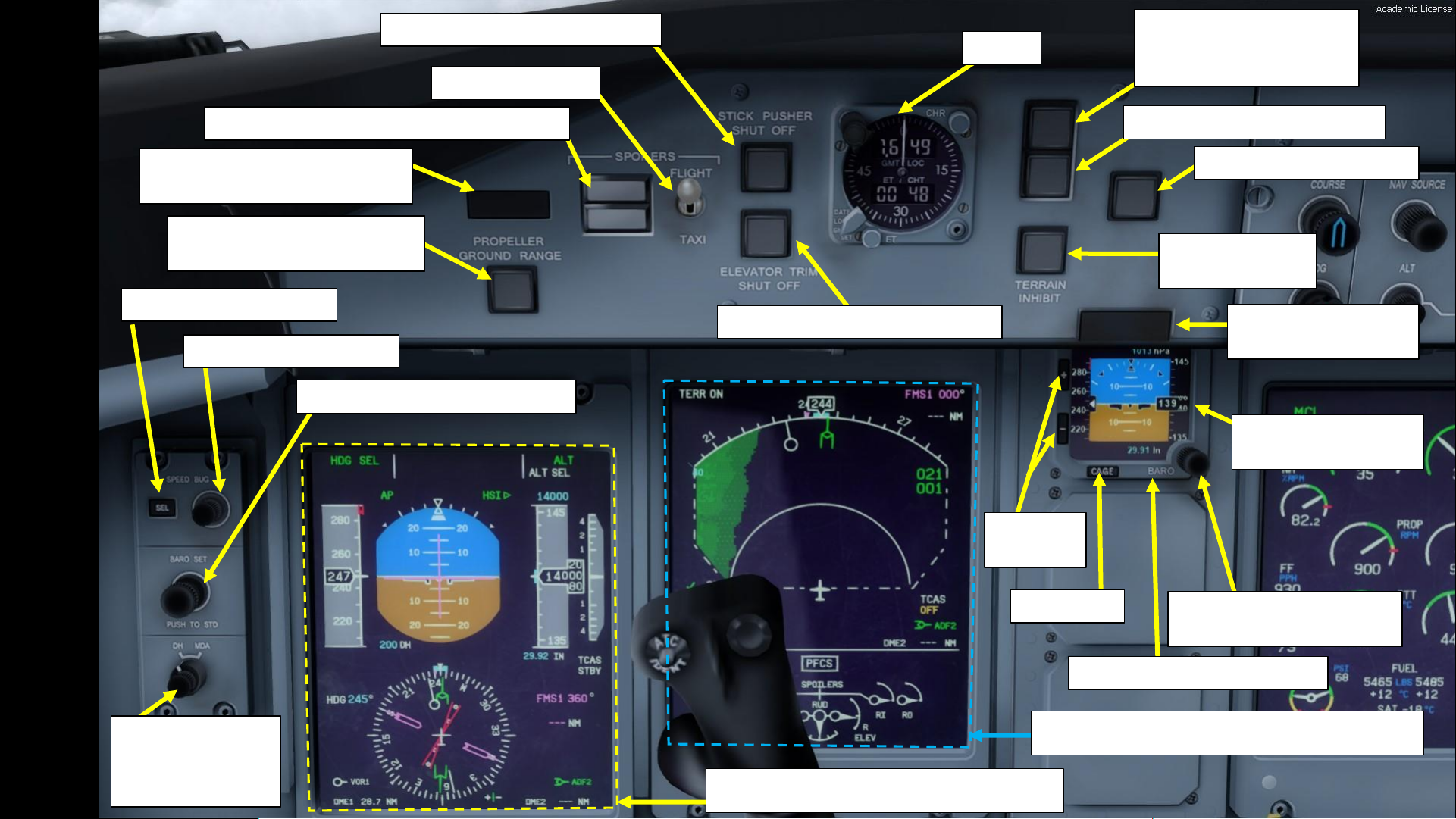
Barometric Pressure Setting
Adjustment Knob
Standby ADI (Attitude
Director Indicator)
Caution Press-toReset Switchlight
Terrain Warning
Inhibit Switch
Autopilot Disengage Light
PULL UP GPWS (Ground-
Proximity Warning
System) Test Light
BELOW G/S (Glide Slope) Light
Clock
Elevator Trim Push Switchlight
Stick Pusher Shut Off Switchlight
Flight/Taxi Switch
Roll Outboard & Roll Inboard Spoilers Lights
Roll Outboard & Roll Engine Fire
Press-to-Reset Switchlight
Propeller Ground (Beta) Range
Lights (1/2)
Speed Bug Select Button
Speed Bug Setting Knob
Barometric Pressure Setting Knob
DH/MDA Switch
Selects Designated
Height or Minimum
Descent Altitude
PFD 1 (Primary Flight Display)
MFD 1 (Multifunction Display)
Barometric Pressure Setting
Cage Reset
Brightness
Control
Page 14
14
PART 2
–
COCKPIT LAYOUT
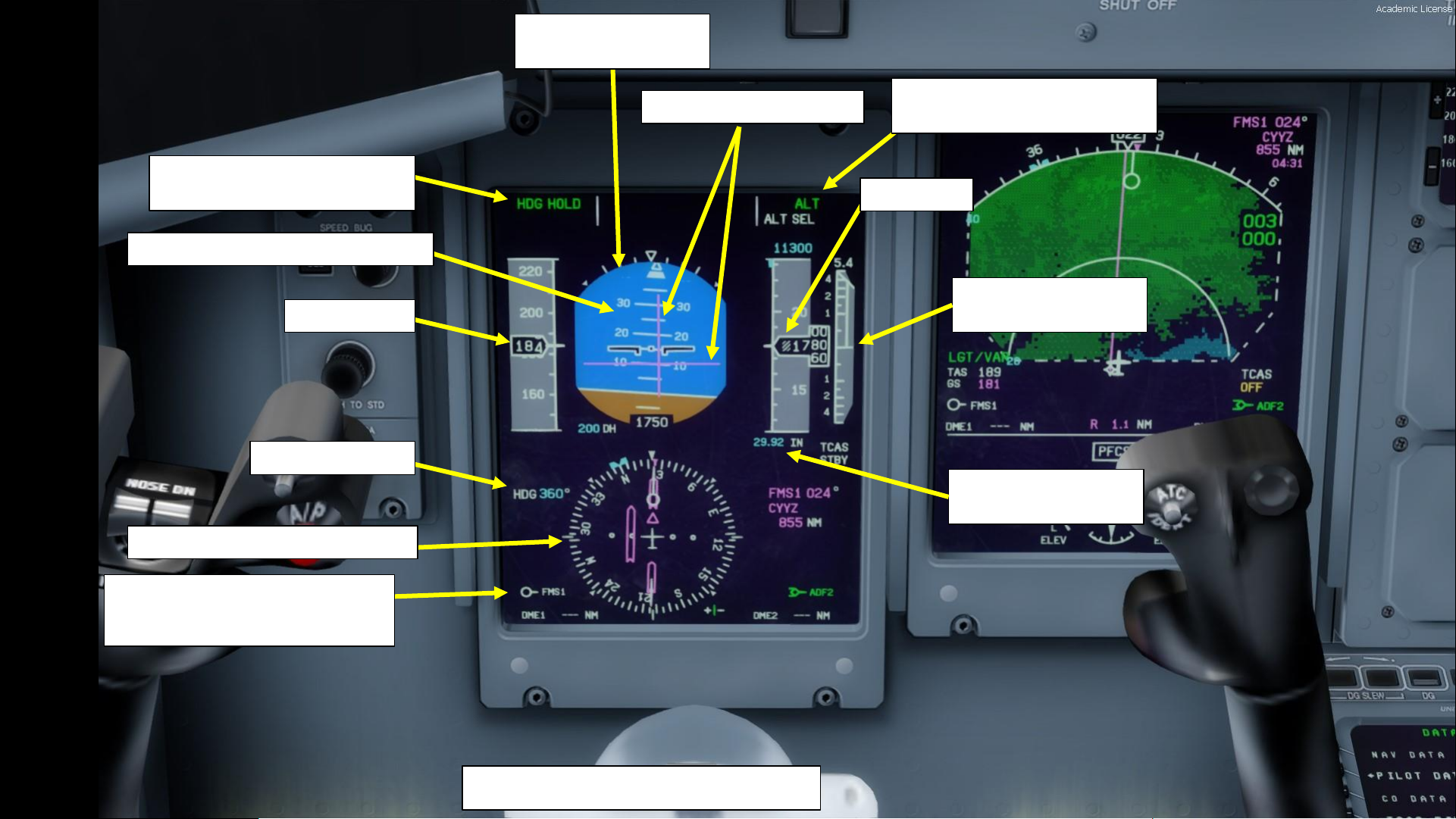
PFD 1 (Primary Flight Display)
Airspeed (kts)
Selected Heading
AFCS (Automatic Flight Control
System) Lateral Mode
Flight Director Indications
Primary ADI (Attitude
Director Indicator)
Aircraft Pitch Ladder (Angle in deg)
HSI (Horizontal Situation Indicator)
Selected Navigation Source Data
FMS: Flight Management System
VOR: VHF Omnidirectional Range Beacon
Vertical Speed
(x1000 ft per minute)
Barometric Pressure
Setting (in Hg or hPa)
Altitude (ft)
AFCS (Automatic Flight Control
System) Vertical Mode
Page 15
15
PART 2
–
COCKPIT LAYOUT
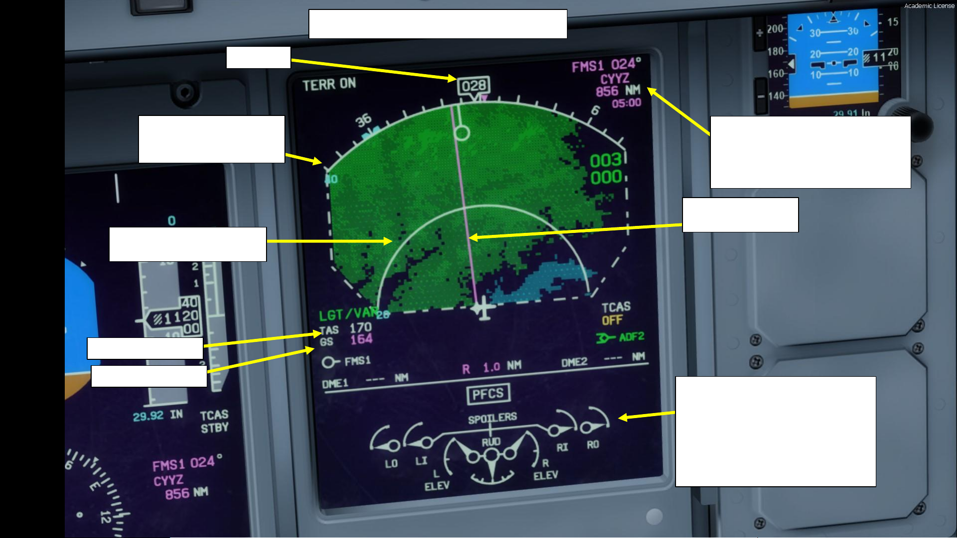
MFD 1 (Multifunction Display)
Terrain Radar Information
GREEN = LAND
BLUE = WATER
Navigation Page Display
(Top Down View)
Navigation Source Data
FMS: Flight Management System
024: Heading to next waypoint
CYYZ: Next Waypoint (Toronto)
856 NM: Distance to next waypoint
Heading
Magenta Line
Leads to next waypoint
PFCS (Primary Flight Control System)
LO: Left Outer Aileron Indication
LI: Left Inner Aileron Indication
RO: Right Outer Aileron Indication
RI: Right Inner Aileron Indication
RUD: Rudder Indication
L ELEV: Left Elevator Indication
R ELEV: Right Elevator Indication
True Airspeed (kts)
Ground Speed (kts)
Page 16
16
PART 2
–
COCKPIT LAYOUT
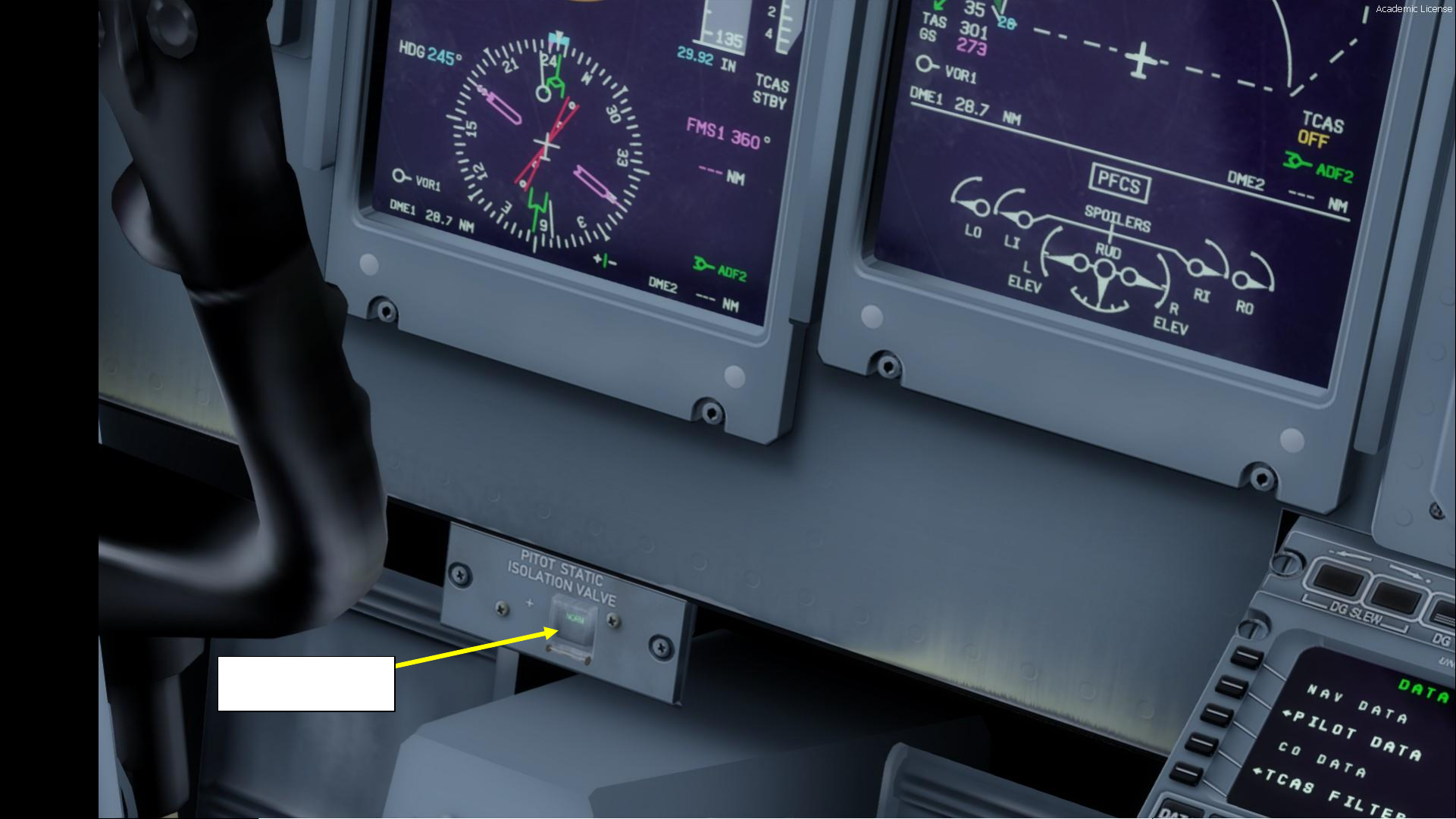
Pitot Static Isolation
Valve Switch
Page 17
17
PART 2
–
COCKPIT LAYOUT
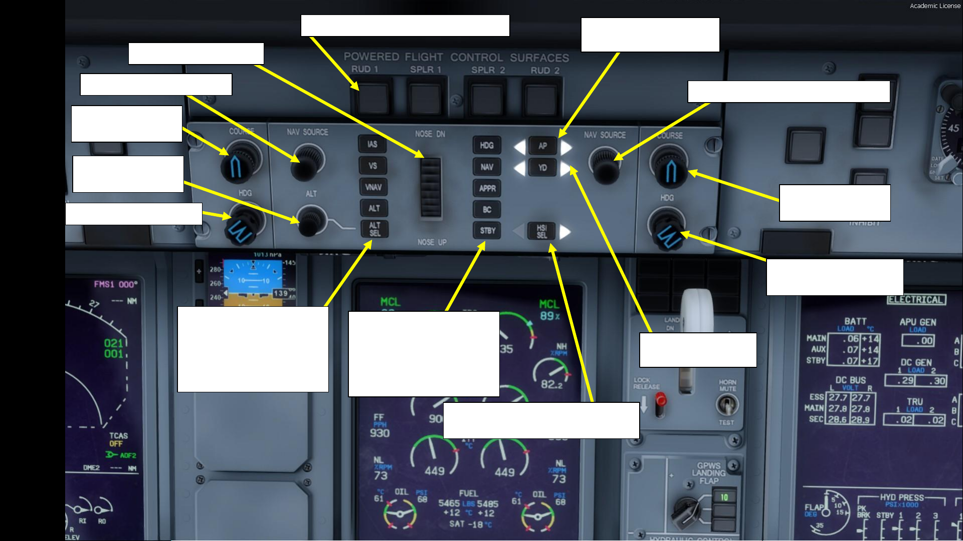
Rudder & Spoilers PUSH OFF switches
Autopilot Pitch Wheel
Navigation Source Selector
Course Selection
Knob
Altitude Selection
Knob
Heading Selection Knob
Autopilot Mode Selectors
IAS: Indicated Airspeed
VS: Vertical Speed
VNAV: Vertical Navigation
ALT: Altitude Hold
ALT SEL: Selected Altitude
Autopilot Mode Selectors
HDG: Heading
NAV: Navigation
APPR: Approach
BC: Back Course
STBY: Standby
HSI (Horizontal Situation Indicator)
Source Selector for Autopilot
Yaw Damper Button
Illuminated = Engaged
Autopilot Master Switch
Illuminated = Engaged
Navigation Source Selector (Copilot)
Course Selection
Knob (Copilot)
Heading Selection Knob
(Copilot)
Page 18
18
PART 2
–
COCKPIT LAYOUT
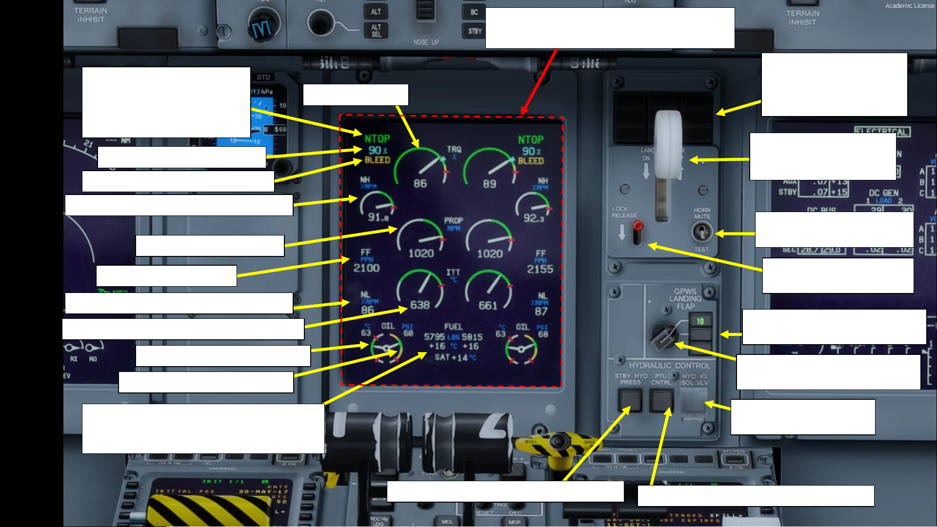
ED: Engine Display
Displays EFIS (Electronic Flight Instrument System) data
Engine Rating Mode
NTOP: Normal Takeoff
MCL: Maximum Climb
MCR: Maximum Cruise
MTOP: Maximum Takeoff Power
Engine Rating Target Torque (%)
Engine Torque (%)
NH (High-Pressure Turbine Speed) (% RPM)
NP (Propeller Speed) (RPM)
Fuel Flow (lbs per hour)
NL (Low-Pressure Turbine Speed) (% RPM)
Engine Oil Temperature (deg C)
Fuel Quantity – Left & Right Tank (lbs)
Fuel Temperature – Left & Right Tank (deg C)
SAT: Static Air Temperature (deg C)
ITT (Interstage Turbine Temperature) (deg C)
Engine Bleed Status Annunciation
Engine Oil Pressure (psi)
Landing Gear Lever
DOWN = GEAR DEPLOYED
UP = GEAR RETRACTED
Landing Gear Indications
Yellow: Gear Doors Open
Green: Gear Down
Red: Gear Unsafe
Landing Configuration
Warning Mute & Test Switch
Gear Handle Lock Release
Switch
GPWS (Ground Proximity Warning
System) Landing Flap Indication
GPWS (Ground Proximity Warning
System) Landing Flap Control
Standby Hydraulic Pressure Pump switch
PTU (Power Transfer Unit) Control switch
No. 3 Hydraulic System
Isolation Valve switch
Page 19
19
PART 2
–
COCKPIT LAYOUT
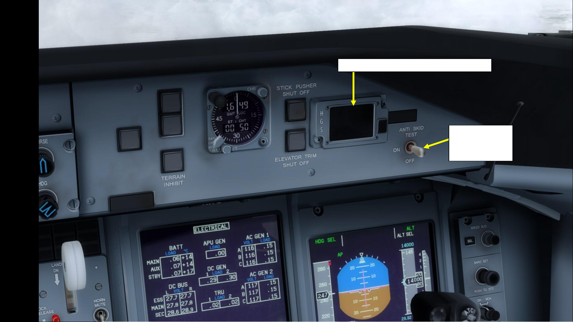
HGS (Head-Up Guidance System) Advisory Panel
Anti-Skid Switch
DOWN = OFF
MIDDLE = ON
UP = TEST
Page 20
20
PART 2
–
COCKPIT LAYOUT
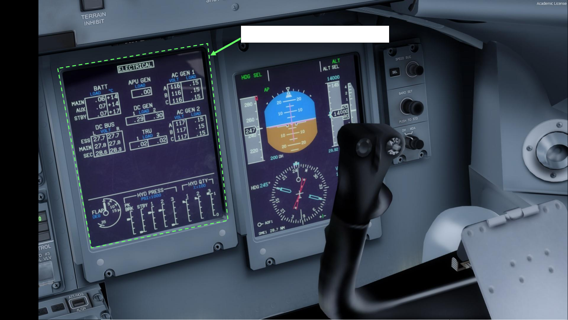
MFD 2 (Multifunction Display)
Page 21
21
PART 2
–
COCKPIT LAYOUT
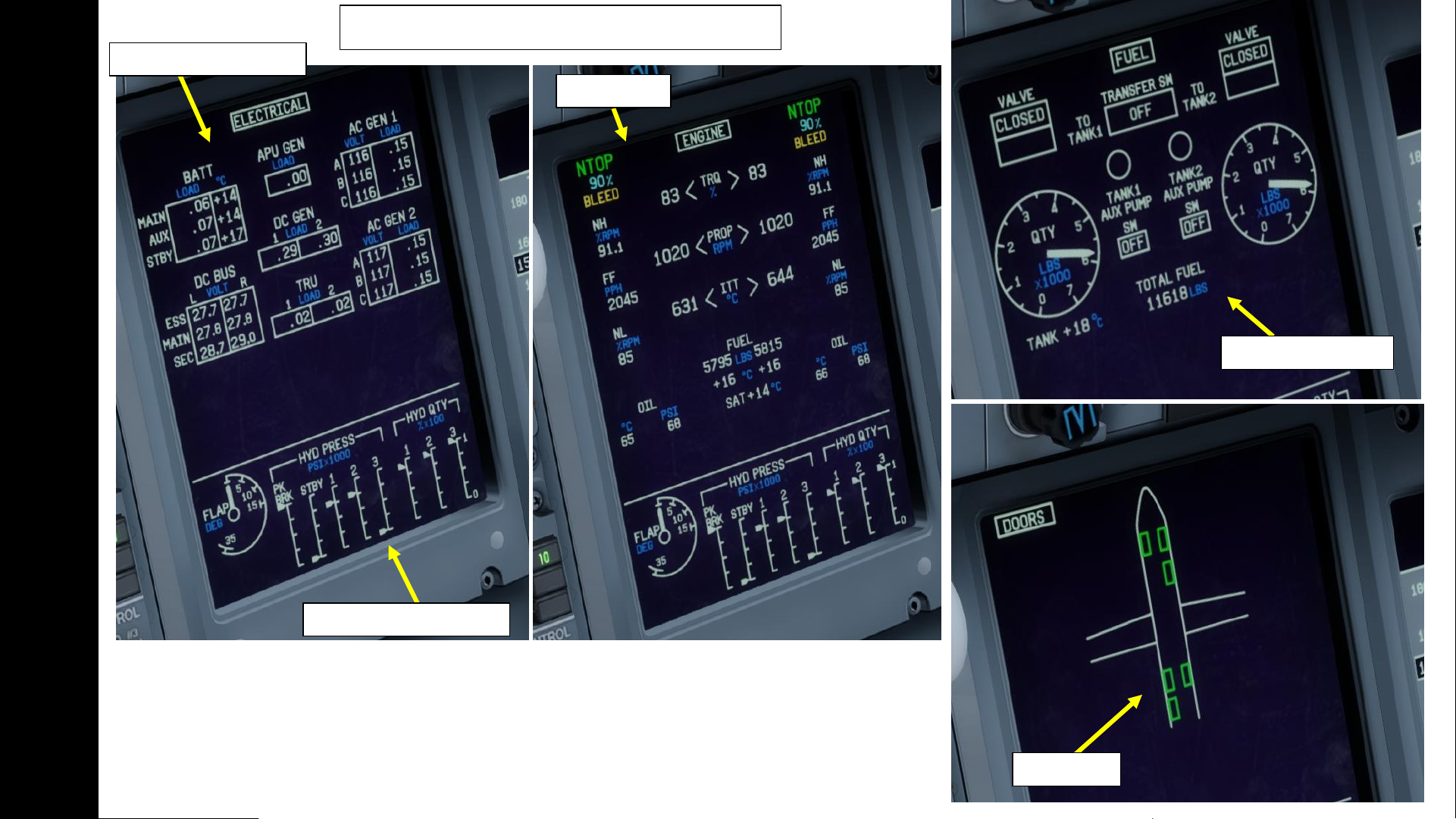
MFD 2 (Multifunction Display) Pages
Electrical Systems Page
Hydraulic Systems Page
Engine Page
Fuel Systems Page
Doors Page
Page 22
22
PART 2
–
COCKPIT LAYOUT
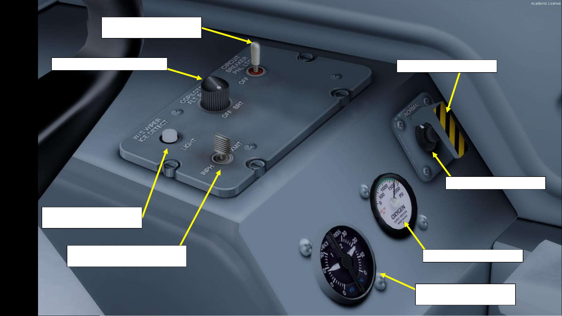
Forward Outflow Valve Guard
Circuit Breaker Panel Lighting
Control Toggle Switch
Copilot’s Side Panel Dimmer Knob
Windshield Wiper Ice
Detection Light Pushbutton
Microphone Interphone/Transmit
Toggle Switch
Forward Outflow Valve Control
Oxygen Supply Pressure (psi)
De-Ice Pneumatic Pressure (left
and right systems)
Page 23
23
PART 2
–
COCKPIT LAYOUT
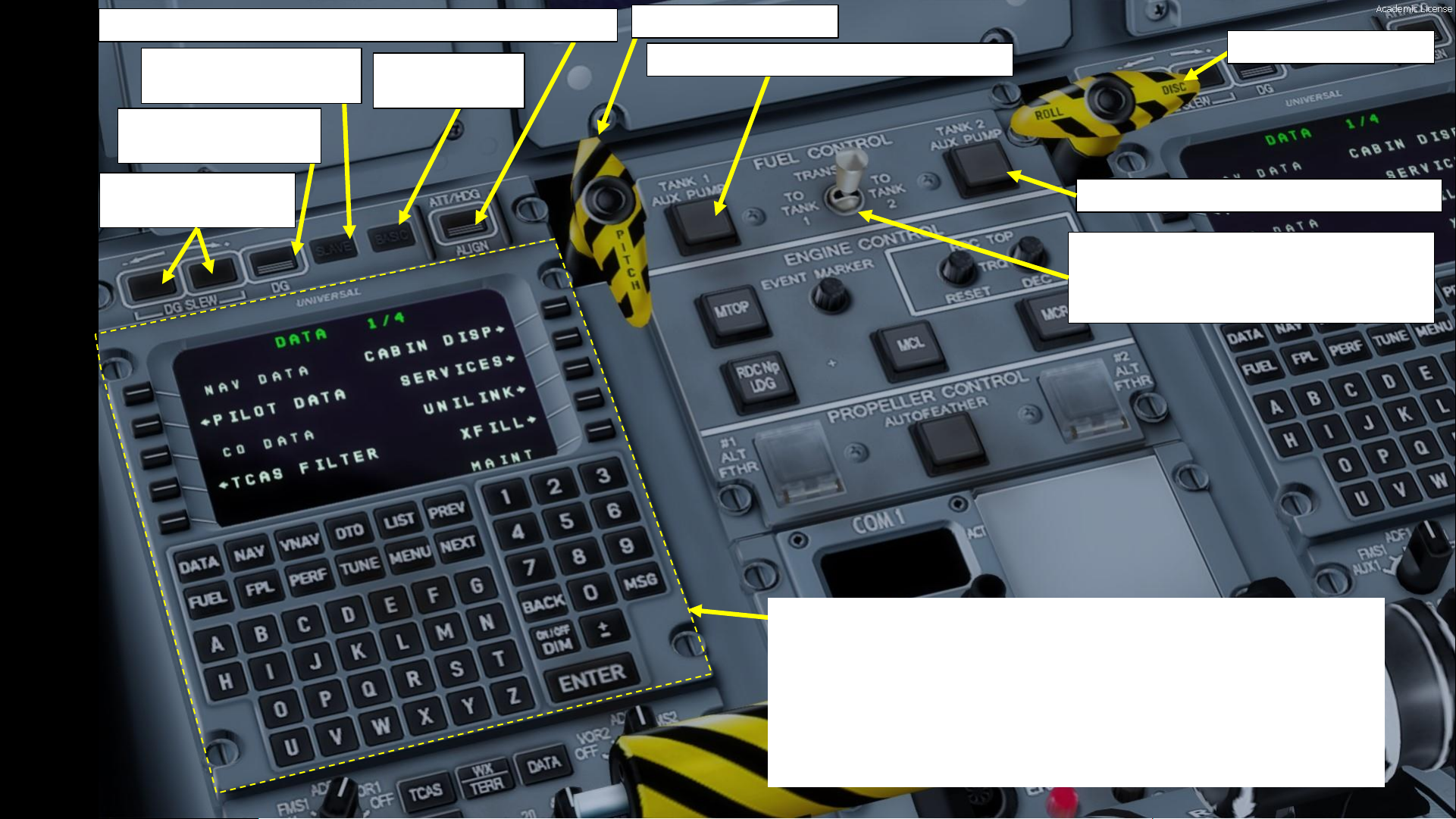
AHRS (Attitude & Heading Reference System) Alignment Switch
FMS (Flight Management System) CDU (Multifunction Control Display Unit)
• An FMS is a specialized computer system that automates a wide variety of in-flight
tasks, reducing the workload on the flight crew to the point that modern civilian aircraft
no longer carry flight engineers or navigators. A primary function is in-flight
management of the flight plan.
• The FMS is controlled through the MCDU physical interface.
• The FMS sends the flight plan for display to the Electronic Flight Instrument
System (EFIS), NavigationDisplay (ND),or Multifunction Display (MFD).
AHRS Pitch Basic
Mode Switch
AHRS Directional Gyro
Slew Buttons
AHRS Directional Gyro
Slaved Mode Switch
AHRS Directional Gyro
Mode Switch
Pitch Disconnect Handle
Roll Disconnect Handle
Fuel Tank 1 Auxiliary Pump Pushbutton
Fuel Tank 2 Auxiliary Pump Pushbutton
Fuel Transfer Switch
LEFT / TO TANK 1: Transfers fuel to left fuel tank
MIDDLE: OFF
RIGHT / TO TANK 2: Transfers fuel to right fuel tank
Page 24
24
PART 2
–
COCKPIT LAYOUT
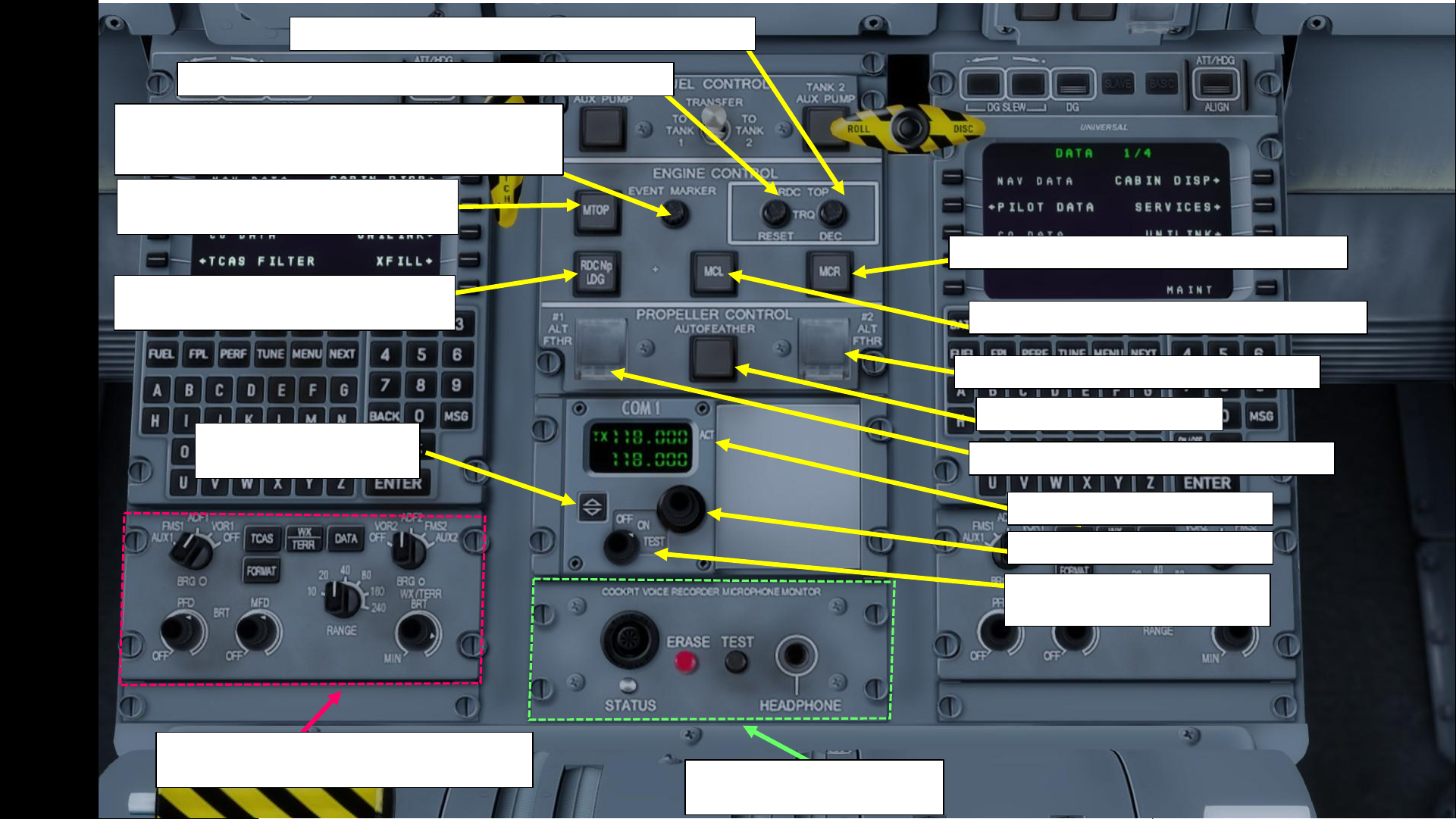
MTOP (Maximum Takeoff Power) Engine
Rating Selector
RDC NP LDG (Reduced Propeller Speed
Landing) Engine Rating Selector
Event Marker Pushbutton
Stores a data snapshot in the Engine Management System
leading up to the recorded event (i.e. engine malfunction)
RDC TOP (Reduced Takeoff Power) Engine Mode Reset Button
RDC TOP (Reduced Takeoff Power) Engine Mode Selector
MCR (Maximum Cruise) Engine Rating Selector
MCL (Maximum Climb) Engine Rating Selector
No. 2 Propeller Alternate Feathering Button
No. 1 Propeller Alternate Feathering Button
Autofeather Pushbutton
COM 1 Radio Frequency Display
COM 1 Radio Frequency Tuner
COM 1 Power Selector
OFF / ON / TEST
COM 1 Activate Frequency
Button
Cockpit Voice Recorder
Microphone Monitor Panel
EFCP (Electronic Flight Instrumentation System
Control Panel)
Page 25
25
PART 2
–
COCKPIT LAYOUT
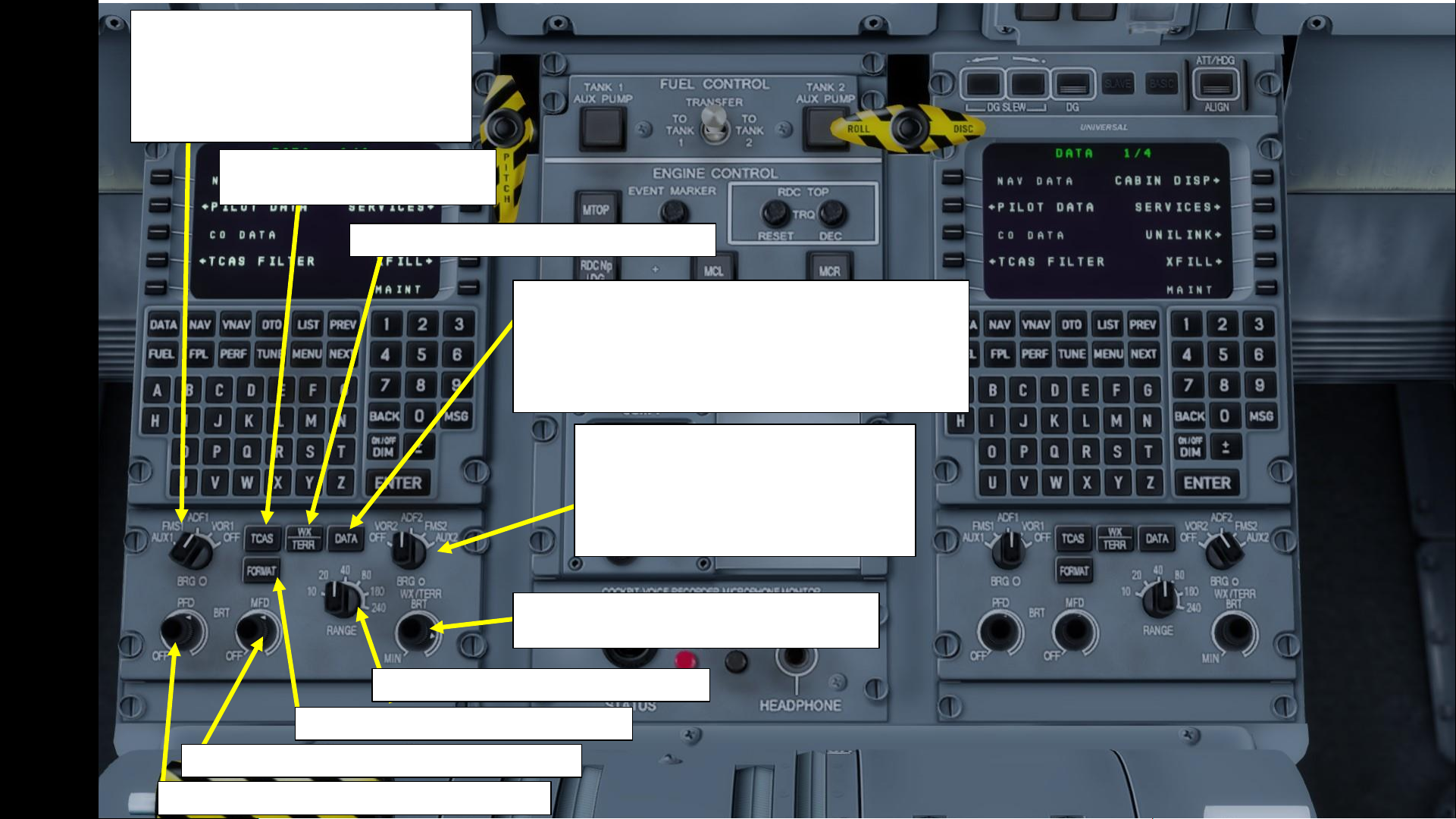
Left Navigation Source Selector 1
AUX1: Auxiliary Equipment (i.e. MLS)
FMS1: Flight Management System 1
ADF1: Automatic Direction Finder 1
VOR1: VHF Omnidirectional Range 1
OFF
TCAS (Traffic & Collision
Avoidance System) Button
WX/TERR (Weather /Terrain Radar) Button
FMS Data Selection Button
• Push 1 shows 10 nearest navigation aids on MFD NAV page
• Push 2 shows the 10 nearest airports on MFD NAV page
• Push 3 shows navigation aids + airports on MFD NAV page
• Push 4 removes all options
• Push & HOLD removes all nav aids + airports
Left Navigation Source Selector 2
AUX2: Auxiliary Equipment (i.e. MLS)
FMS2: Flight Management System 2
ADF2: Automatic Direction Finder 2
VOR2: VHF Omnidirectional Range 2
OFF
WX/TERR (Weather /Terrain Radar)
Brightness Control
Navigation Display Range Selector (nm)
MFD Navigation Display Format Switch
PFD (Primary Flight Display) Brightness Control
MFD (Multifunction Display) Brightness Control
Page 26
26
PART 2
–
COCKPIT LAYOUT
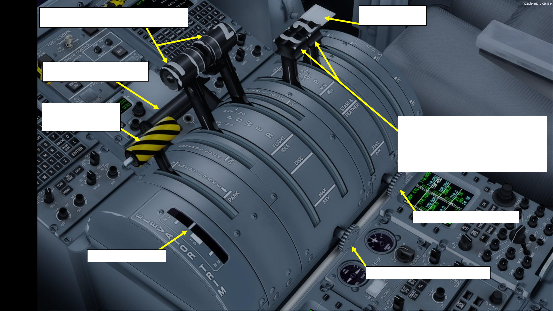
Throttle Power Levers
Positions: MAX / FLIGHT IDLE / DISC / MAX REV
Condition Levers
• MAX: 1020 RPM (Normal Takeoff Rating)
• MCL: 900 RPM (Maximum Climb Rating)
• MIN: 850 RPM (Maximum Cruise Rating)
• START & FEATHER: Propeller Blade Angle is Feathered
during engine start
• FUEL OFF: Fuel shutoff
Condition Lever Friction Control
Throttle Power Lever Friction Control
Elevator Trim Indicator
Parking Brake
FWD: OFF (DISENGAGED)
AFT: ON (ENGAGED)
Control Lock Lever
Physically blocks throttle power levers
Flaps Control Lever
0 / 5 / 10 / 15 / 35 deg
Page 27
27
PART 2
–
COCKPIT LAYOUT
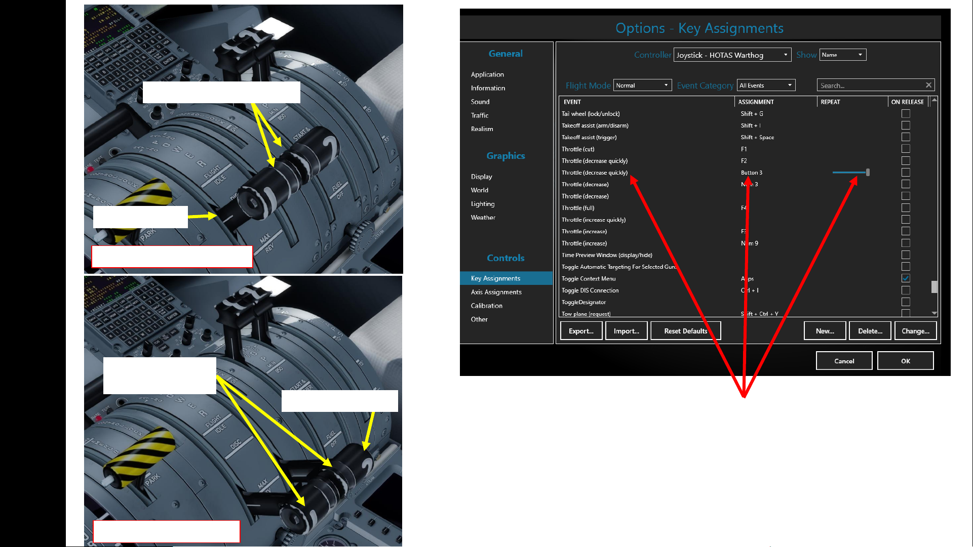
The Thrust Reverser lever can be moved by pressing and holding the “Throttle (decrease
quickly)” control mapped to your joystick. Make sure that the “Repeat” slider is set fully
to the right. The default key binding is “F2”.
Take note that the Reverse Thrust lever can only be engaged if your throttle is at IDLE.
The reason for that is a mechanical stopper that prevents you from engaging thrust
reversers at high throttle settings.
No Reverse Thrust Generated
Reverse Thrust Generated
Throttle at IDLE
Thrust Reversers Disarmed
Throttle at MAX REV
Thrust Reversers
Armed
Page 28
28
PART 2
–
COCKPIT LAYOUT
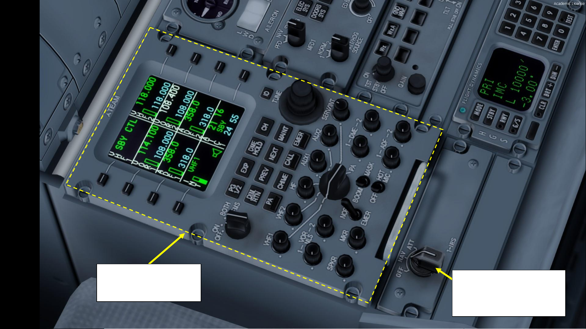
ARCDU 1 (Audio & Radio
Control Display Unit)
Frequencies: UHF1 / UHF2 / VOR1 /
VOR2/ ADF1 / ADF2 / INT / ATC1
IRS (Inertial Reference System) 1
Mode Switch
OFF: OFF
NAV: Navigation Mode
ATT: Attitude Information Only
Page 29
29
PART 2
–
COCKPIT LAYOUT
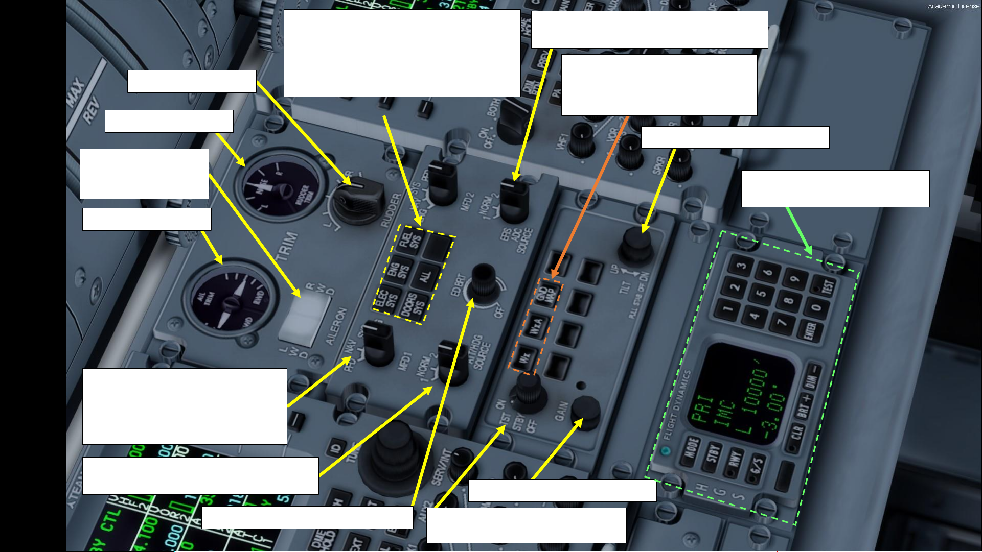
Rudder Trim Indicator
Aileron Trim Indicator
Rudder Trim Control
Aileron Trim Control
LWD: Left Wing Down
RWD: Right Wing Down
MFD (Multifunction Display) 1 Mode
PFD: Primary Flight Display
NAV: Navigation Page
SYS: System Page
ENG: Engine Page
EFIS (Electronic Flight Instrument System)
Attitude/Heading Source Selector
MFD (Multifunction Display) Page Selector
Electrical Systems Page
Engine Systems Page
Fuel Systems Page
Doors Systems Page
Test Button (not simulated)
EFIS (Electronic Flight Instrument System)
ADC (Air Data Computer) Source Selector
ED (Engine Display) Brightness Control
WX (Weather Radar) Power Switch
OFF / STANDBY / TEST / ON
WX (Weather Radar) Gain Control
WX (Weather Radar) Mode Buttons
WX: Weather Radar Mode
WXA: Weather Radar Alert Mode
GND MAP: Ground Map Mode
WX (Weather Radar) Tilt Control
HGS (Head-Up Guidance System)
Control Panel
Page 30
30
PART 2
–
COCKPIT LAYOUT
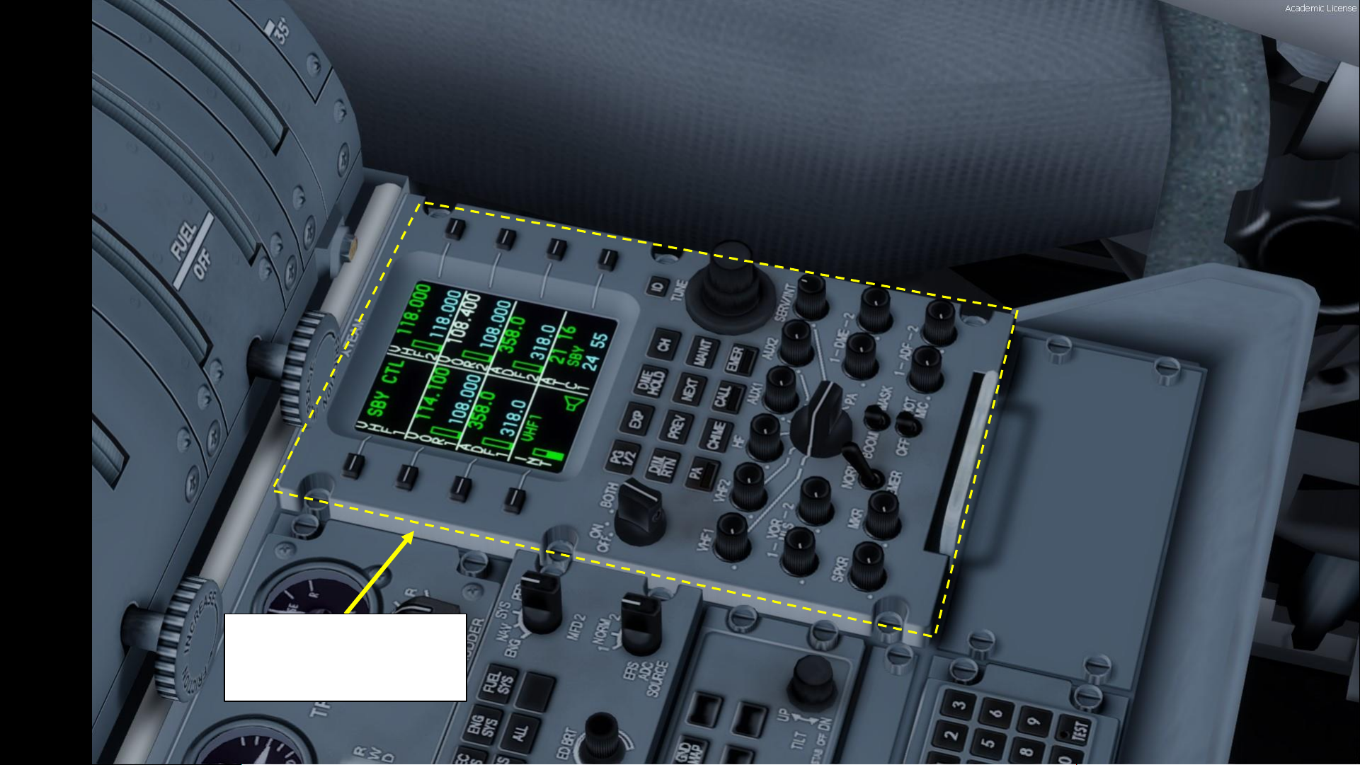
ARCDU 2 (Audio & Radio
Control Display Unit)
Frequencies: UHF1 / UHF2 / VOR1 /
VOR2/ ADF1 / ADF2 / INT / ATC1
Page 31

31
PART 2
–
COCKPIT LAYOUT
Landing Gear Locking Pins
(stowed in bag)
Nose Landing Gear
Emergency Release Lever
Page 32

32
PART 2
–
COCKPIT LAYOUT
Caution & Warning Panel
Magnetic Compass
Page 33

33
PART 2
–
COCKPIT LAYOUT
Page 34

34
PART 2
–
COCKPIT LAYOUT
HGS (Head-Up
Guidance System)
HGS Brightness Control
HGS Stow/Deploy Handle
Page 35

35
PART 2
–
COCKPIT LAYOUT
Pressure Differential between
Cabin and Surrounding
Environment (psi)
Current Pressure Altitude
Inside Cabin (x1000 ft)
Pressure Altitude Change Rate
(x1000 ft per minute)
Taxi Lights Switch
Landing Flare
Lights Switch
Landing Approach
Lights Switch
Pilot Side Window Heat Switch
Wiper Control Switch
Windshield De-Icing
Mode Selector
Pitot Static Heat Probe 2 Switch
Pitot Static Heat Probe 1 Switch
Pitot Static Standby Probe Switch
Boot Air (Airframe
Deice Air Isolation
Valve) Switch
Page 36

36
PART 2
–
COCKPIT LAYOUT
Flight Data Recorder Switch
ELT (Emergency Locator
Transmitter) Switch
PFD (Primary Flight Display) Altimeter Units Switch
(ft / ft+m)
Propeller De-Icing
Status Indicator
Increase Reference Speeds Switch
Engine Intake De-Ice Indicators
Propeller De-Ice Mode Switch
De-Ice Wing Boots
Status Indicators
Airframe De-Ice
Mode Switch
De-Ice Tail Boots
Status Indicators
Airframe Manual
De-Ice Switch
Page 37

37
PART 2
–
COCKPIT LAYOUT
Generator 1 Switch
Generator 2 Switch
Main Bus Tie Switch
Bus Fault Reset Switch
External Power Switch
Standby Battery Switch
Auxiliary Battery Switch
Main Battery Switch
Battery Master
Switch
Page 38

38
PART 2
–
COCKPIT LAYOUT
Engine 1 Fuel Valve Indicator
Engine 1 Extinguisher Aft/Forward Bottle Selector Switch
APU Extinguisher
Bottle Arming Light
APU (Auxiliary Power Unit) Fuel Valve Indicator
APU Fire Extinguish Button
APU Fire Detected Light
APU Extinguisher Bottle Low / Fault light
APU Fire Test Switch
Engine 1 Fire Detection Fault Lights
(Systems A & B)
Engine 1 Fire Extinguish Handle
(Illuminates when fire is detected)
Engine 1/2 Fire Detection Test
Selector Switch
Engine 2 Fire Extinguish Handle
(Illuminates when fire is detected)
Aft Baggage Compartment
Fire Detection Panel
Page 39

39
PART 2
–
COCKPIT LAYOUT
Emergency Exit Hatch Handle
Landing Gear Alternate Release Handle
Page 40

40
PART 2
–
COCKPIT LAYOUT
Overhead Console Panel Lighting Brightness Control
Glare Shield Panel Lighting Brightness Control
Forward Center Console Panel Lighting Brightness Control
Aft Center Console Panel Lighting Brightness Control
Storm Lights Switch
Dome Lights Switch
AC External Power Switch
AC Generator 2 Switch
AC Generator 1 Switch
Air Conditioning Duct
Temperature (deg C)
Recirculation Fan Switch
Engine 1 Bleed Switch
Engine 2 Bleed Switch
Bleed Flow Mode Selector
MIN/NORM/MAX
Temperature Indicator Switch
Cabin Duct
Cabin
Flight Compartment Duct
PACKS (Pressurization & Air
Conditioning Kit) 1 & 2 Switches
OFF / MANUAL / AUTOMATIC
Flight Compartment
Temperature Regulator
Cabin Compartment
Temperature Regulator
Page 41

41
PART 2
–
COCKPIT LAYOUT
Selected Landing Altitude
Indicator (x1000 ft)
Landing Altitude Selector
Manual Pressure Control
Pressurization Mode Selector
Pressurization Fault Light
Manual Forward Outflow Valve Control
Engine 2 Ignition Selector
Engine 1 Ignition Selector
APU (Auxiliary Power Unit) Power Switch
APU (Auxiliary Power Unit) Start Switch
APU (Auxiliary Power Unit) Generator Switch
APU (Auxiliary Power Unit) Bleed Air Switch
Note: APU Bleed Air only works if engine bleed air
switches are OFF
Engine Start Button
Engine Start Selector Button (1/2)
Page 42

42
PART 2
–
COCKPIT LAYOUT
Emergency Lights Switch
Fasten Seatbelts Light Switch
No Smoking Light Switch
Caution/Advisory Panel Lights Test Switch
Caution/Advisory Lights Dimming / Brightness switch
Wing Inspection Light Switch
White/Red Anti-collision
Lights Switch
Position Lights Switch
Logo Light Switch
Page 43

43
PART 2
–
COCKPIT LAYOUT
Circuit Breaker Panel
Side Window De-Mist Control
AFT = OPEN
FWD = CLOSED
Low Level Vents Control
AFT = OPEN
FWD = CLOSED
Page 44

44
PART 2
–
COCKPIT LAYOUT
Circuit Breaker Panel
Microphone &
Headset Jacks
Oxygen Crew Mask
Page 45

45
In real life, you cannot just fly an Q400 wherever and whenever you please.
Just like on land, the sky is littered with an intricate network of waypoints and
aerial highways. Therefore, it is necessary to plan your flight route and to
determine how much fuel you will need to carry in order to reach your
destination.
In order to do this, we will use a tool called “Online Flight Planner” available
here: http://onlineflightplanner.org/
There are a number of fuel planners available online. These estimates may or
may not be very accurate. There are specific charts created by Bombardier to
come up with accurate fuel estimates which are unfortunately not available to
the public. Therefore, for the sake of simplicity we will just use a rule of thumb
that’s good enough for the purpose of this tutorial.
PLANNING THE FLIGHT
PART 3
–
FLIGHT PLANNING
Page 46

46
Today’s flight will start from TORONTO / LESTER B. PEARSON INTERNATIONAL AIRPORT
(CYYZ) and our destination will be MONTREAL / PIERRE-ELLIOTT TRUDEAU
INTERNATIONAL AIRPORT (CYUL).
Using the “Online Flight Planner” available here: http://onlineflightplanner.org/ we will
enter the Departure airport (CYYZ), the Destination airport (CYUL) and the AIRAC Cycle
desired (we will use the AIRAC cycle 1710 as explained on the next page).
Click on CREATE PLAN to generate a flight plan.
Bombardier Dash 8 Q400
Click CREATE PLAN
Choose your fuel units: LBS in our case
PART 3
–
FLIGHT PLANNING
PLANNING THE FLIGHT
Page 47

47
In aviation, an Aeronautical Information Publication (or AIP) is defined by the International Civil Aviation Organization as a publication issued by or with the authority of a state and
containing aeronautical information of a lasting character essential to air navigation. It is designed to be a manual containing thorough details of regulations, procedures and other information pertinent to flying
aircraft in the particular country to which it relates. It is usually issued by or on behalf of the respective civil aviation administration. AIPs are kept up-to-date by regular revision on a fixed cycle. For operationally
significant changes in information, the cycle known as the AIRAC (Aeronautical Information Regulation And Control) cycle is used: revisions are produced every 56 days (double AIRAC cycle) or every 28 days
(single AIRAC cycle). These changes are received well in advance so that users of the aeronautical data can update their flight management systems (FMS). (Source:
https://en.wikipedia.org/wiki/Aeronautical_Information_Publication )
In other words, some Youtube tutorials might show you flight routes with certain waypoints that got changed with more recent AIRAC updates. Some waypoints or even airports may not exist anymore.
Therefore, you have two options:
1. Plan your flight using the default AIRAC cycle programmed in the FMC when it was first released by Majestic Software during early October, 2017 (period 10) 2017 (AIRAC cycle 1710), which is what we will
do for this tutorial. This option is free and simple if you fly alone. However, if you fly with online ATCs in multiplayer that use the latest AIRAC database, you should go for the second option.
2. Plan your flight using the latest AIRAC cycle. You will need to update your AIRAC, SID and STAR database by using a paid subscription service called “Navigraph”, which is available here
https://www.navigraph.com/FmsDataManualInstall.aspx .
PART 3
–
FLIGHT PLANNING
PLANNING THE FLIGHT
Note:
• For the FSX version of the Q400, use
AIRAC cycle 1304 since this version
was released in late april 2013
• For the Prepar3d Version 4.1 of the
Q400, use AIRAC cycle 1710.
Page 48

48
FUEL
For a flight of approx. 290 nm, fuel planning can be estimated with the following graph from
MJCJavelin (http://majesticsoftware.com/forums/discussion/344/fuel-planning/p1), which he
obtained by programing a regression and an interpolationbased on fuel consumption tables:
Imperial Units
Fuel for flight = Fuel Quantity for required distance (300 nm approx.) on graph below
= 1.3 tons = 2600 lbs (or 1.3 tons x 2000 lbs/ton)
Reserve Fuel = 2500 lbs (approximative figure)
Total (Block) Fuel = Fuel for Flight + Reserve Fuel = 5100 lbs
Note: An alternate way to calculate the fuel for flight is to use a fuel consumption of 1300 lbs
of fuel per engine per hour of flight. For an hour-long flight from Montreal to Toronto, the fuel
quantity would be: Fuel for Flight = 1300 lbs/hour x 2 engines x 1 hour = 2600 lbs approx.
PART 3
–
FLIGHT PLANNING
PLANNING THE FLIGHT
Page 49

49
FLIGHT ROUTE (POTENTIAL)
The flight route we could take from onlineflightplanner.com is:
CYYZ SID MIGLO STAR CYYZ
But what does it all mean? Here is a breakdown of this route:
• Depart from Toronto Lester B. Pearson Airport (CYYZ)
• Follow the SID (Standard Instrument Departure) route from CYYZ to MIGLO
• Navigate to MIGLO VOR
• Follow the STAR (Standard Terminal Arrival Route) from MIGLO to CYUL
• Land at Montreal Pierre-Elliott Trudeau Airport (CYUL)
Not our flight plan
(thank god)
PART 3
–
FLIGHT PLANNING
PLANNING THE FLIGHT
WOAH, STOP RIGHT THERE!
Did you really think the flight plan would be that easy? No Sir/Madam!
We will spice things up a bit and slightly modify the flight plan. Why?
Because that simple flight plan will not force you to know how to plug in
airways and use the FMS (Flight Management System) to do cool things
like giving you lists of waypoints already stored in the database.
Relax, we won’t do a complicated flight plan like Boeing’s custom “787shaped” flight plan. We will just modify a little bit the existing flight plan
using Sky Vector, a great tool available for free online. See next page.
Page 50

50
FLIGHT ROUTE (ACTUAL) <- This is what we’ll use
The actual flight route we will take is:
CYYZ SID DEDKI Q913 IGSEB DCT MIGLO STAR CYUL
Write this route down. This is the one we will plug in the Flight Management System (FMS).
But what does it all mean? Here is a breakdown of this route:
• Depart from Toronto Lester B. Pearson Airport (CYYZ)
• Follow the SID (Standard Instrument Departure) route from CYYZ to DEDKI
• Follow Q913 airway
• Navigate to IGSEB VOR
• Navigate directly from IGSEB to MIGLO VOR (“DCT” means “Direct to”)
• Follow the STAR (Standard Terminal Arrival Route) from MIGLO to CYUL
• Land at Montreal Pierre-Elliott Trudeau Airport (CYUL)
PART 3
–
FLIGHT PLANNING
PLANNING THE FLIGHT
CYYZ DEDKI
IGSEB
MIGLO
CYUL
Airway
Q913
SKY VECTOR
https://skyvector.com/
Page 51

51
WHAT IS A SID AND A STAR?
A SID (Standard Instrument Departure) is a small initial route
which leads an aircraft from the runway they've just taken off
from to the first point in his/her intended route. An airport usually
has a lot of aircraft departing from it's runways. To save confusion
(and for safety), a busy airport will publish standard routes from
it's runways to the various routes away from that airport. This way
a controller can be sure that even if a steady stream of aircraft is
leaving the airport they will all be following in a nice neat line, one
behind the other (that's the idea anyhow!).
Standard routes are the preferred method to fly from airport to
airport. This is why we use a flight plan generator. Arriving at an
airport is just the same. The STARs (STandard Arrival Routes) are
also published in chart form and allow you to fly into an airport
using standard procedures. This way, less communication is again
needed with the controllers as (once you have declared your
intention or been given a route to fly by name) the controller and
you both know exactly how you are going to approach the airport.
The end of the STAR route will normally leave your aircraft at a
position where controllers can give you final instructions to set
you up for a landing.
SIDs and STARs are quite similar to highways; they have speed
limits and altitude restrictions at certain waypoints to make sure
the air traffic is flying safely and on the same trajectory. The FMC
(Flight Management Computer) will automatically try to respect
these restrictions.
In other words, you can see SIDs and STARs like road junctions in
the sky that lead to other waypoints and airways from or to your
desired airport. One airport has many SIDs and STARs.
Typically, SIDs and STARs are provided by the ATC (Air Traffic
Controller). Since we’re doing a tutorial, I will just give you the SID
and STAR to plug in the FMC.
PART 3
–
FLIGHT PLANNING
Page 52

52
PLANNING THE DEPARTURE - SID
1: Gate B22
These charts are for the SID (Standard Instrument Departure)
from Toronto Pearson (CYYZ) to DEDKI. We intend to:
1. Spawn at Gate B22 (personal preference)
2. Taxi towards runway 05 (orientation: 057) using taxiways
3, Alpha-Juliet (AJ), Alpha (A), November (N), Echo (E),
Golf (G), Hotel (H) and holding point H6.
3. Depart from CYYZ using the SID from CYYZ to DEDKI
(DEDKI4) to a target altitude of 3000 ft (FL030).
NOTE: the chart shows DEDKI3 (valid for November 2014) since
I could not find the chart for DEDKI4 (valid for January 2018).
Therefore, we will assume DEDKI3 and DEDKI4 are roughly the
same for the purpose of this tutorial.
4. Climb to a cruising altitude of 24,000 ft
2: Runway 05
(holding point H6)
PART 3
–
FLIGHT PLANNING
3: SID towards DEDKI
Page 53

PLANNING THE
APPROACH - STAR
These charts are for the STAR (Standard Terminal Arrival
Route) from MIGLO to Montreal Pierre-Elliott Trudeau
(CYUL). We intend to:
1. Come from MIGLO waypoint
2. Fly from MIGLO towards the HABBS3 arrival route.
3. Follow the STAR (MIGLO -> REEDO -> IGVUD -> KAVSU ->
ARVIE -> HABBS -> XULTA)
4. Follow the approach towards the runway, guided by the
CYUL airport’s ILS (InstrumentedLanding System).
5. Land at Montreal (CYUL) on runway 06L (orientation:
060 Left)
PART 3
–
FLIGHT PLANNING
Fun fact: The HABBS STAR name
actually comes from the Montreal
Canadiens hockey team, nicknamed
the “Habs”.
53
Page 54

54
So there it is! This is more or less all the information you need to plan your flight!
PLANNING THE FLIGHT - SUMMARY
Flight Plan Input to FMC
PART 3
–
FLIGHT PLANNING
CYYZ SID DEDKI Q913 IGSEB DCT MIGLO STAR CYUL
Page 55

55
MCDU/FMC IN A NUTSHELL
Most of the aircraft setup and flight planning will be done with the help of the
MCDU, which encompasses various systems such as the FMC system.
MCDU: Multifunction Control Display Unit
FMC: Flight Management Computer
Fundamental component of a modern airliner's avionics. The FMC is a
component of the FMS (Flight Management System), which is a specialized
computer system that automates a wide variety of in-flight tasks, reducing
the workload on the flight crew to the point that modern civilian aircraft no
longer carry flight engineers or navigators. A primary function is in-flight
management of the flight plan. All FMS contain a navigation database. The
navigation database contains the elements from which the flight plan is
constructed. The FMS sends the flight plan for display to the Electronic Flight
Instrument System (EFIS), Navigation Display (ND), or Multifunction Display
(MFD).
MCDU DATA PAGE
PART 3
–
FLIGHT PLANNING
Fun fact: FMS installed on the Q400 is the UNS-1E by Universal Avionics
Systems Corporation. It differs significantly from the usual Thales or Rockwell
Collins FMCs you might have already seen on Boeing or Airbus aircraft.
Page 56

56
FMC -> Flight Management Computer
• DATA : Obtains information and status about the FMS, Navigation database and
attached sensors. It also has the “SERVICES” page which is used to simulate ground
crew behavior such as setting a GPU (Ground Power Unit), or removing/installing
landing gear locking pins.
• NAV : Displays navigation data pages.
• VNAV : Vertical Navigation page allows a pilot to define a desired vertical flight
profile along the flight plan route. It also computes deviation from that profile.
• DTO : The “Direct To” key allows the pilot to alter his flight plan.
• FUEL : displays fuel and weight pages.
• FPL : The “Flight Plan” pages access waypoints, stored arrivals, departures, SIDs,
and STARs.
• PERF : The “Flight Performance” page displays in flight performance information
(read-only).
• TUNE : Selects and stores preselected frequencies for each radio.
• LIST : Displays a list of options during data entry
• MENU : Displays a list of alternate formats or options for the FUEL, FPL, NAV,
VNAV or TUNE pages when selected. When the MENU key is active, the letter “M”
will appear in a box on the title line of the selected page.
• PREV/NEXT: Cycles through previous and next page of selected FMC page
• BACK: Backspace (deletes text)
• MSG: Displays messages
• ON/OFF DIM: Turns ON or OFF Flight Management Computer
• ENTER: Enters data
LSK: Line Select Keys
PART 3
–
FLIGHT PLANNING
MCDU/FMC IN A NUTSHELL
Sounds complicated? Don’t worry, it’s much simpler than it looks. We’ll see
how it works in the tutorial section.
Page 57

57
The Q400 is steered on the ground by using a tiller.
However, in Prepar3d or FSX you cannot map a joystick axis to your nosewheel steering tiller:
it’s a limitation of the sim itself. In order to steer the aircraft, Majestic programmed different
options available in their own custom Control Panel; you can either use the mouse to click and
drag on the tiller lever, or you can have the tiller axis mapped to your stick aileron control. I
suggest you use the latter option.
1. The Control Panel will not work properly if it is not run in “Administrator Mode”. Make sure
you have the Control Panel executable “mjc84cspan.exe” property “Run the program as an
administrator” ticked (right-click file & click “Properties” tab). This executable is available in:
C:\Program Files\Lockheed Martin\Prepar3D v4\SimObjects\Airplanes\mjc8q400\cpan
2. Open the MJC8 Q400 control panel (mjc74cpsan.exefile) before starting Prepar3d
a) Open “mjc84cspan.exe” and go in “Flight Controls” tab
b) Click “Ailerons+Mouse” option
c) Click “Apply”
d) You can now start Prepar3d with the desired steering control mode set.
SET UP CONTROLS
PART 3
–
FLIGHT PLANNING
1a
1b
1c
1d
1e
2a
2a
2b
2c
Page 58

58
In Prepar3d or FSX, you will generally spawn with your engines
running. A “cold & dark” start-up means that your aircraft is in an
unpowered state with engines and every other system off. Here is the
procedure to spawn in such a state:
1. Spawn like you normally would at Gate B22 in CYYZ (departure
airport) in the MJC8Q400
2. Set cockpit in cold & dark state
a) Engage Parking Brake lever (AFT = ENGAGED)
b) Set GEN1, GEN2, BUS FAULT RESET, and EXT PWR
switches to OFF
c) Set STBY BATT, AUX BATT, MAIN BATT and BATTERY
MASTER switches to OFF (in that order)
d) Set MAIN BUS TIE to TIE
SPAWN COLD & DARK
PART 3
–
FLIGHT PLANNING
1: Gate B22
2b
2c
2d
2b
2a
Page 59

59
We will dynamically set our fuel, cargo and passenger
loads using the MajesticControl Panel.
3. Open the MJC8 Q400 control panel
(mjc74cpsan.exe file)
a) Open “mjc84cspan.exe”
b) Go in “Weight & Balance” tab
4. Set fuel loads (we will use 8000 lbs takeoff fuel and
5100 trip fuel, leaving us 1900 lbs extra fuel)
5. Set baggage weight (2000 lbs for this flight)
6. Set number of passengers (58 in our case) through
the PAX sections and make sure that the TOM, LM
and ZFM are within the Trim Envelope
7. Click “Calculate”
8. Verify that the Takeoff Mass, Landing Mass and
Zero Fuel Mass are all under their respective MAX
limits as shown on the graph.
9. Once Weight and Balance configuration is deemed
correct, click on “Send Data to Flightsim” to set the
loads on the aircraft.
LOAD FUEL, CARGO & PASSENGERS
PART 3
–
FLIGHT PLANNING
DOI: Dry Operating Index (position
of CG @ Dry Operating Mass)
TOM: Takeoff Mass
LM: Landing Mass
ZFM: Zero Fuel Mass
Trim Envelope Index
Calculates T/O & Trip Fuel
Sends Fuel/Weight
Configuration To Simulation
Trip Fuel: Required fuel for
duration of flight
Takeoff Fuel: Fuel at
moment of takeoff
Baggage weight
Number of
Passengers
Weight and Balance Page
3a
This executable is available in:
C:\Program Files\Lockheed Martin\Prepar3D v4\SimObjects\Airplanes\mjc8q400\cpan
3b
4
5
6
7
8
6
9
Page 60

Note: In real life, when using external power, the pilot switches the battery switches OFF after switching to the external battery source. This
helps protect batteries from depleting while the ground power unit is in use, or from GPU surges, or in the case of a weak GPU which will
make the batteries “discharge” into the GPU. For simplicity’s sake, we will simply leave the batteries ON.
60
10. On Overhead panel, turn on battery power
a) Set BATTERY MASTER, MAIN BATT, AUX BATT and STBY BATT
switches to ON (in that order)
b) Set Main Bus Tie to TIE
c) Press Master Warning and Master Caution lights to reset them
Note: the aircraft will begin a series of Automatic BITs (built-in
tests).
11. OPTIONAL: Go on MCDU main menu to connect ground power unit
(GPU) to the aircraft
a) Power up FMC by pressing and holding the “DIM ON/OFF”
button on the MCDU.
b) Wait for FMC BIT to complete
c) Click on the “ACCEPT” LSK (Line Select Key) once the INIT page
is displayed
d) Press the MCDU “DATA” button
e) Click on the “SERVICES” LSK to enter ground crew services
page.
f) Click on the “GPU REQUEST” LSK to set ground power. The
MCDU will then display “CANCEL” when GPU is set.
12. OPTIONAL: On overhead panel, click on the “EXT PWR” switch to power
connect aircraft to GPU
13. OPTIONAL: On Electrical Systems page, confirm that the “DC EXT PWR
ON” indication is illuminated
NOTE: Steps 11 to through 13 are optional.
POWER UP AIRCRAFT
6b
PART 3
–
FLIGHT PLANNING
11a
10a
10b
10c
11b
11c
11e
11f
11d
11f
11f
12
13
Page 61

61
Fun fact: the engines of the Q400 can be started either with the APU (Auxiliary Power Unit) or with an external electrical power source like a GPU (Ground Power Unit). The aircraft startup procedures vary from company to company. There is a debate as to whether you shoulduse the GPU or not.
The APU of the Dash 8 Q400 are considered by some to be fragile and unreliable. It supplies electrical power and bleed air, while the GPU provides electrical power only. Why would we
need to use a GPU then? Well, a reason for using the GPU when the APU is running is to lessen on the load on the APU. Certain Canadian airlines will use the APU for air conditioning and
the GPU for electrical power during the engine start. The Q400 uses electrical starter generators instead of a pneumatic starter, meaning the engines can start with electric motors
cranking the engines insteadof a starter powered by APU bleed air like standard airliners like the Airbus A320 or the Boeing 737.
Therefore, for simplicity’s sake, we will use both the GPU and the APU in our tutorial, even if real life procedures are a bit different. Keep in mind that this tutorial is done within the
scope of a simulationand should not be used for real life operation of the aircraft.
POWER UP AIRCRAFT
PART 3
–
FLIGHT PLANNING
Ground Power Unit (GPU)
Auxiliary Power Unit (APU)
Auxiliary Power Unit (APU)
Page 62

62
14. Go on MCDU “DATA -> SERVICES -> EXITS” menu to open doors to
communicate with ground crew personnel
a) In DATA -> SERVICES page, click “EXITS” LSK
b) Click on the LSKs next to FWD PAX, AFT PAX, AFT BAG, and
SERVICE doors to open them (or use the “LSHIFT + E” key
binding)
c) Doors will now be open
15. Click on “RETURN” to go back to the “SERVICES” page
16. Make sure the landing gear pins are removed
a) If the GEAR PINS option shows “GND OPS ONLY”, this means
that either the parking brake is not set or that doors are not open
b) If the GEAR PINS option shows “INSTALL”, this means that the
landing gear pins are removed and are stored in the bag with red
flags behind the copilot’s seat. Your landing gears will now deploy
or retract normally. In that case, you can proceed to the next
page
c) If the GEAR PINS option shows “STOW”, this means that the
landing gear pins are still installed (notice the empty bag behind
the copilot’s seat). Your landing gears will remain locked in their
current position no matter what you do with the landing gear
lever. In that case, you should click on the LSK next to “STOW” to
stow the landing gear pins.
CHECK LANDING GEAR PINS
PART 3
–
FLIGHT PLANNING
14a
14b
14c
15
16a
16b
16c
14c
Landing Gear Pins
Stowed
Landing Gear Pins
Installed
Page 63

63
17. The AHRS (Attitude & Heading Reference System,
which drives the flight instruments) alignment
starts immediately when the battery switches are
ON. The alignment phase is on-going when the
ATT/HDG ALIGN light illuminates and lasts between
45 sec and 2 minutes.
18. The positional information of the navigation
systems are provided by GPS and/or VOR-based
RNAV, which do not require any alignment. The IRS,
on the other hand, acts as a short time supplement
to the GPS in this aircraft. If you see the “GPS
INTEG” caution on the PFD (Primary Flight Display),
this means that the FMC is not turned on.
19. Make sure the IRS (Inertial Reference System)
switch is set to NAV. If it’s not, set it to OFF for 5-10
sec, then set it back to NAV to restart IRS
alignment. You can monitor the alignment process
in the second DATA page of the FMC by pressing
the DATA button two times.
AHRS & IRS ALIGNMENT
PART 3
–
FLIGHT PLANNING
17a
17b 17c
17a
Appears if
FMC is OFF
17d
Alignment
complete
AHRS Alignment
is in process
AHRS Alignment
is in process
19
IRS1 D -> OFF
19
IRS1 ALIGN -> Alignment Phase
IRS1 NAV -> Alignment Complete
AHRS Alignment
is in process
Page 64

64
PART 3
–
FLIGHT PLANNING
17. Initialize the FMC (Flight Management Computer) if
you have not done it already
a) Power up FMC by pressing and holding the
“DIM ON/OFF” button on the MCDU.
b) Wait for FMC BIT (Built-In Test) to complete
c) Click on the “ACCEPT” LSK (Line Select Key)
once the INIT page is displayed
18. Go on FMC (Flight Management Computer) and
initialize your flight plan
a) Press the FPL page button
b) Type “CYYZ” (Pearson Airport) on the
MCDU keypad and press “ENTER”.
c) Click LSK next to “ACCEPT” on the
confirmation screen to validate entry.
d) Type “CYUL” (Trudeau Airport) on the
MCDU keypad and press “ENTER”.
e) Click LSK next to “ACCEPT” on the
confirmation screen to validate entry.
FMC SETUP – FLIGHT PLAN
PART 3
–
FLIGHT PLANNING
17a
17b
17c
18a
18b
18d
18c
18b
18d
18e
18f
Page 65

65
PART 3
–
FLIGHT PLANNING
19. Go on FMC (Flight Management Computer) and set up your
departure parameters
a) Press the FPL page button
b) Press the MENU page button
c) Select LSK next to “DEPART” to enter Departure sub-
menu
d) Type desired runway selection number (runway 05 in
our case, so we type “1” since it is selection item
number 1) on the MCDU keypad and press “ENTER”
FMC SETUP – FLIGHT PLAN
(DEPARTURE)
PART 3
–
FLIGHT PLANNING
Runway 05
(holding point H6)
Gate B22
19a
19b
19b
19d
19d
19c
Page 66

66
PART 3
–
FLIGHT PLANNING
20. Go on FMC (Flight Management Computer) and set up your
departure parameters for the SID (Standard Instrument
Departure)
a) Type desired SID selection number (DEDKI4 in our case,
so we type “6” since it is selection item number 6) on
the MCDU keypad and press “ENTER”
b) Type desired SID transition selection number (Runway
05 in our case, so we type “1” since it is selection item
number 1) on the MCDU keypad and press “ENTER”
c) All departure data is now entered in the FMC.
d) You can click on the FPL page button to verify new
entries.
FMC SETUP – FLIGHT PLAN
(DEPARTURE)
PART 3
–
FLIGHT PLANNING
SID towards DEDKI
20a
20a
20b
20b
20d
20c
Page 67

67
PART 3
–
FLIGHT PLANNING
21. Go on FMC (Flight Management Computer) and set
up your arrival parameters
a) Press the FPL page button
b) Press the MENU page button
c) Select LSK next to “ARRIVE” to enter
Arrival sub-menu
d) Type desired runway selection number
(runway 06 Left in our case, so we type “1”
since it is selection item number 1) on the
MCDU keypad and press “ENTER”
FMC SETUP – FLIGHT PLAN
(ARRIVAL)
PART 3
–
FLIGHT PLANNING
21a
21b
21b
21c
21d
21d
Page 68

68
PART 3
–
FLIGHT PLANNING
PART 3
–
FLIGHT PLANNING
22. Go on FMC (Flight Management Computer) and set up your
departure parameters for the SID (Standard Instrument
Departure)
a) Type desired STAR selection number (HABBS3 in our
case, so we type “2” since it is selection item number
2) on the MCDU keypad and press “ENTER”
b) Type desired STAR transition selection number
(MIGLO VOR waypoint in our case, so we type “3”
since it is selection item number 3) on the MCDU
keypad and press “ENTER”. In other words, we will
enter the STAR from the MIGLO transition point.
c) Type desired approach selection number (I06L ILS in
our case, so we type “1” since it is selection item
number 1) on the MCDU keypad and press “ENTER”.
d) All arrival data is now entered in the FMC.
e) You can click on the FPL page button to verify new
entries.
FMC SETUP – FLIGHT PLAN
(ARRIVAL)
22a
22a
22b
22c
22d
Page 69

69
PART 3
–
FLIGHT PLANNING
23. Go on FMC (Flight Management Computer) and set up your
remaining waypoints and airways
a) Press the FPL page button and click NEXT button to show
page 2
b) Click on LSK next to the next waypoint after DEDKI to
select it (it should be a discontinuity reading “NO LINK”
in flashing amber).
c) Press the LIST button
d) Click on LSK next to the AIRWAYS sub-menu
e) Type desired airway selection number from DEDKI
waypoint (airway Q913 in our case, so we type “1” since
it is selection item number 1) on the MCDU keypad and
press “ENTER”
f) Type desired next waypoint selection number after
DEDKI (IGSEB VOR waypoint in our case, so we type “1”
since it is selection item number 1) on the MCDU
keypad and press “ENTER”.
g) IGSEB waypoint has now been added after DEDKI and
will be accessible through airway Q913
h) We will now have to check for discontinuities
FMC SETUP – FLIGHT PLAN
(COMPLETE ROUTE)
CYYZ SID DEDKI Q913 IGSEB DCT MIGLO STAR CYUL
23b
23a
23c
23d
23e
23e
23f
23f
23g
Page 70

70
PART 3
–
FLIGHT PLANNING
24. Go on FMC (Flight Management Computer) and remove remaining
discontinuities from the flight plan
a) Click on LSK next to the next “NO LINK” waypoint (in our case
after IGSEB).
b) Click on LSK next to “DELETE” two times to delete
discontinuity between IGSEB and MIGLO.
c) Click on NEXT button until you reach page 4 of the FPL menu.
d) Click on LSK next to the next “NO LINK” waypoint (in our case
after XULTA).
e) Click on LSK next to “DELETE” two times to delete
discontinuity between XULTA and the I06L approach fix.
f) Most discontinuities should now be removed. You can cycle
through waypoints by pressing the “FORMAT” button while
being in the FPL page and pressing “NEXT” or “PREV” to cycle
through waypoints on the MFD. Press the “FORMAT” button
again to return to the normal navigation display.
FMC SETUP – FLIGHT PLAN
(CLEAN UP DISCONTINUITIES)
24a
24b
24c
24b
“NO LINK”
DELETED!
24d
24e
24f
“NO LINK”
DELETED!
24f
MFD in FORMAT mode
MFD in NAV mode
Page 71

71
PART 3
–
FLIGHT PLANNING
FMC SETUP – FUEL & WEIGHT
25. Check the MJC8 Q400 control panel and find your resulting Zero
Fuel Mass (ZFM)
a) Open “mjc84cspan.exe”
b) Go in “Weight & Balance” tab
c) Zero Fuel Weight/Mass is 53502 lbs
d) Our total fuel is 8000 lbs
26. Enter Fuel & Weight information in FMC (Flight Management
Computer)
a) Press the FUEL page button. You will see a BASIC WT entry
that is erroneous. Let’s fix this.
b) Press LSK next to ZFW, type “53502” ZFW value we
obtained from the control panel and press ENTER.
c) Press LSK next to FUEL ONBOARD, type “8000” total fuel
value we obtained from the control panel and press ENTER.
d) The Gross Weight will automatically be calculated based on
the two values we entered previously. We’re good to go!
Zero Fuel Mass (lbs)
This executable is available in:
C:\Program Files\Lockheed Martin\Prepar3D v4\SimObjects\Airplanes\mjc8q400\cpan
Total Fuel Mass (lbs)
26a
25d
25d
26b
26c
26d
Page 72

72
PART 3
–
FLIGHT PLANNING
FMC SETUP – CROSS-FILL
24a
27. Initialize the second FMC (Flight Management
Computer) on the First Officer’s side
a) Power up FMC by pressing and holding the
“DIM ON/OFF” button on the MCDU.
b) Wait for FMC BIT (Built-In Test) to complete
c) Click on the “ACCEPT” LSK (Line Select Key)
once the INIT page is displayed
d) Press the DATA button to open up the Data
page
e) Press the LSK next to the XFILL sub-menu
f) Press the LSK next to the XFILL FLIGHT
PLAN sub-menu to start transfer the flight
information from the captain’s FMC to the
first officer’s FMC
g) Wait for the CROSSFILL RECEIVE IN
PROGRESS to complete
h) Press the LSK next to the XFILL FUEL sub-
menu to start transfer the fuel information
from the captain’s FMC to the first officer’s
FMC
i) Wait for the CROSSFILL RECEIVE IN
PROGRESS to complete
27d
27e
27f
27h
27g 27i
Page 73

73
PART 3
–
FLIGHT PLANNING
ARCDU – UHF RADIO
28. Set ARCDU (Audio & Radio Control Display Unit) radio frequencies to CYYZ (Toronto) and
CYUL (Montreal) airport ATIS (Automatic Terminal Information Service) in order to gather
meteo conditions and atmospheric pressure
a) Power up ARCDU by setting radio power switch to ON.
b) Press the LSK next to UHF1 to select frequency 1. Frequency 1 will be highlighted in
white.
c) Scroll mousewheel over TUNE knob to tune UHF1 radio frequency 1 to the Toronto
ATIS (120.825 MHz).
d) Press LSK next to UHF1 to validate frequency 1.
e) Repeat steps b) to d) to set UHF1 frequency 2 to the Montreal ATIS (133.700).
f) Press LSK next to UHF1 to cycle active frequency (in green) to CYYZ ATIS (120.825).
g) Write down the altimeter setting broadcast by Toronto ATIS. In our case, altimeter
setting is 29.52 in Hg (inches of mercury).
h) Set COM1 radio switch to ON
28g
28a
28b 28c
28d
28f
28h
Page 74

74
PART 3
–
FLIGHT PLANNING
ARCDU – RADIO NAV
29. Set ARCDU (Audio & Radio Control Display Unit) ILS frequency to CYUL (Montreal) airport ILS frequency
a) Press the « FPL » button to enter the Flight Plan page
b) Press the « MENU » button to enter the FPL MENU
c) Click the LSK next to « APPR PLAN ».
d) ILS frequency for Montreal runway 06L is 109.30 MHz.
e) Link ARCDU to FMS (Flight Management System) by setting radio power switch to FMS.
f) Press the LSK next to VOR1 to select frequency 1. Frequency 1 will be highlighted in white.
g) Scroll mousewheel over TUNE knob to tune VOR1 radio frequency 1 to the Montreal ILS (109.30 MHz).
h) Press LSK next to VOR1 to validate frequency 1. Frequency will now read “ILS1” instead of “VOR1”.
i) Repeat steps f) to h) to set VOR2 frequency 1 to the Montreal ILS (109.30 MHz) to make sure both
FMCs track the same ILS frequency.
29a
29b
29c
29d
29f
29e
29g
29h
29h
Page 75

75
PART 3
–
FLIGHT PLANNING
CABIN PRESSURE &
ALTIMETER SETTING
30. Set altimeter barometric setting on the PFD
(Primary Flight Display) to 29.52 in Hg, as stated by
the Toronto ATIS.
31. Set standby ADI (Attitude Director Indication)
barometric setting to 29.52 in Hg, as stated by the
Toronto ATIS.
32. Set landing cabin pressure altitude setting to
approx. 100 ft (CYUL airport elevation is 118 ft).
Take note that the gauge is in thousands of feet.
30
30
31
32
32
Page 76

76
PART 3
–
FLIGHT PLANNING
WEATHER RADAR TEST
33. Power up and test Weather radar
a) Press the WX/TERR button to togglebetween TERRAIN MAP
(EGPWS, or Enhanced Ground Proximity Warning System) and
WEATHER RADAR display
b) Set weather radar mode to WX
c) Set weather radar switch to TEST
d) Check that WX TEST occurscorrectly
e) Set weather radar switch to ON
f) Confirm that WEATHER RADAR display shows WX ON
g) Press WX/TERR button back to TERRAIN MAP
33a
33c
33b
33b
33d
33e
33f
33g
33g
Page 77

77
PART 3
–
FLIGHT PLANNING
TCAS TEST
34. Power up and test TCAS (Traffic & Collision Avoidance System)
a) Click the LSK next to ATC1 on the ARCDU to select TCAS menu
b) ATC1 transponder frequency will be highlighted in white when selected
c) Click on the EXP button to expand TCAS menu
d) Press the LSK next to the TEST option to start TCAS BIT (Built-In Test)
e) Wait for the BIT to complete
f) Confirm that TEST OK appears on navigation display
g) Click and hold LSK next to ATC1 to set TCAS mode to TA ONLY (Traffic Advisory Only)
h) Confirm that TA ONLY is in AUTO mode. If not, press the TCAS power button.
i) To return ARCDU to main page, click on PG 1/2 button.
34a
34b
34c
34d
34e
34e
34f 34h
34h
34g
34i
Page 78

78
PART 3
–
FLIGHT PLANNING
V-SPEEDS SETTING
35. Find V-Speeds
a) Press FUEL button on the MCDU to find our
Gross Weight: 61502 lbs
b) The airport altitude at CYYZ (Toronto) is 173 m,
or 567 ft
c) Find VR, V2, VFRI & VCLIMB for a Flaps 5
takeoff for 62000 lbs and 2000 ft to be
conservative. V1 is assumed equal to VR.
d) V1: 131 kts
e) VR: 131 kts
f) V2: 132 kts
V1 is the Decision Speed (minimum airspeed in the takeoff, following
a failure of the critical engine at VEF, at which the pilot can continue
the takeoff with only the remaining engines), VR is the rotation speed
(airspeed at which the pilot initiates rotation to obtain the scheduled
takeoff performance), and V2 is Takeoff Safety Speed (minimum safe
airspeed in the second segment of a climb following an engine failure
at 35 ft AGL).
g) V
FRI
: 162 kts (142 + 20 kts)
Flaps Retraction Initiation Speed. Table gives us 142 kts, but since
we have possible snow and icing conditions above 1000 ft, we will
increase that value by 20 kts since Bombardier requires to have
the INCR REF SPEEDS switch to ON, which increases the stall
warning speed by 20 kts and provides us a safe margin.
h) V
CLIMB
: 174 kts (154 + 20 kts)
Final Takeoff Speed. Table gives us 154 kts, but we will increase
that value by 20 kts for the same reason as mentioned above.
i) To set V-Speeds, press the SEL button to select V1 (highlighted)
and scroll mousewheel on SPEED BUG knob to set its value.
j) Repeat previous step for VR, V2, VFRI (full triangle) and VCLIMB
(empty triangle).
k) V-Speed selector will automatically be unselected.
36. Set DH/MDA switch (Decision Height / Mean Descent Altitude) to MDA
and scroll mousewheel on knob to set accelerationaltitude to the airport
elevation + 1000 ft (567 ft + 1000 ft = 1567 ft) rounded up to 1570 ft.
35a
35c
35c
35i
35j
V1
VR
V2
VCLMB
VFRI
36
MDA
1570 ft
36
36
Page 79

79
PART 3
–
FLIGHT PLANNING
V-SPEEDS REFERENCE TABLES
These speed tables are available on the Majestic Software website:
http://majesticsoftware.com/mjc8q400/downloads.html
Page 80

80
PART 3
–
FLIGHT PLANNING
TRIM SETTING & AUTOPILOT SETUP
37. Set elevator trim in the middle of the TO (Takeoff)
white line as shown.
38. Press the YD (Yaw Damper) button to set it to ON
39. Make sure the HSI (Horizontal Situation Indicator)
SELECT button has the arrow pointing to the pilot’s
seat (left).
40. Rotate the NAV SOURCE knob to make sure the
navigation systems source is the FMS1 (pilot’s Flight
Management System)
41. Click on the TAKEOFF/GO AROUND button on the
throttles to arm the Go Around (GA) autopilot
mode
42. Rotate the ALT knob and set the autopilot altitude
target to 3000 ft
Note: Canadian law restricts our speed below 3000
ft to 200kts
43. Press the ALT SEL button to arm the altitude select
autopilot mode
44. Press the HDG (Heading) button to arm the heading
autopilot mode
45. Rotate the HDG knob and set the autopilot heading
target to 057 (CYYZ runway 05 heading is 057
according to Jeppesen chart)
37
38
39
40
40
40
41
41
42
43
42
43
44
44
45
45
45
Page 81

81
PART 3
–
FLIGHT PLANNING
DOORS
46. Verify that all doors are closed
a) Press the DOORS SYS page
b) Look for any door that is open (red)
47. Close any door that is still open by going on MCDU
“DATA -> SERVICES -> EXITS” menu
a) In DATA -> SERVICES page, click “EXITS” LSK
b) Click on the LSKs next to FWD PAX, AFT
PAX, AFT BAG, or SERVICE doors to close
them if required (or use the “LSHIFT + E”
key binding)
c) All doors should be in green (closed)
46a
46b
47c
47c
ALL DOORS CLOSED
47a
47a
47a
47b
47c
46b
PAX DOOR OPEN
Page 82

82
ENGINE START
APU
AUXILIARY
POWER UNIT
FUEL
IGNITION
ELECTRICAL POWER
(ELECTRICAL STARTER)
GROUND
POWER CART
ENGINE
(RUNNING)
ENGINE START SELECTOR
&
ENGINE START BUTTON
&
THROTTLE POSITION
ENGINE
IGNITION
SWITCH
APU GENERATOR
APU BLEED AIR
(USED FOR PNEUMATIC SYSTEMS)
EXTERNAL POWER
ENGINE GENERATOR
(ENGINE CROSS-START)
ENGINE BLEED AIR
(USED FOR PNEUMATIC SYSTEMS)
ENGINE START SELECTOR AT 1 OR 2, ENGINE
START BUTTON PUSHED & THROTTLE AT DISC
FUEL STARTER VALVE CONTROLS FUEL FLOW
CONTROLLED BY FADEC
IGNITION SELECTION SWITCH – NORM
IGNITION CONTROLLED BY FADEC
PART 4
–
START
-UP PROCEDURE
NOTE: For those who are used to fly Boeing and Airbus aircraft, you will notice
that the Q400 PW150A engine does not require bleed air to start since it has an
electrical starter instead of a pneumatic one. This is pretty common among
smaller regional aircraft.
ENGINE START-UP
Page 83

83
ENGINE START
APU
AUXILIARY
POWER UNIT
APU GENERATOR
BATTERY SWITCHES ON
EXTERNAL POWER
ENGINE START SELECTOR AT 1 OR 2
ENGINE START BUTTON PRESSED
THROTTLE AT DISC
ENGINE IGNITION SELECTOR - NORM
FUEL STARTER VALVE
IGNITER
APU POWER SWITCH & APU START SWITCH ON
NOTE: It is usually common practice to start your engines during pushback.
We will start our engines before that for simplicity.
PART 4
–
START
-UP PROCEDURE
ENGINE START-UP
Page 84

1. On Overhead Panel, press on the APU PWR switch. Wait
5-6 seconds for the BIT (Built-In Test) to complete after
the switchlights have flashed.
2. Press the APU START switch. The “START” indication will
illuminate while the start sequence is active and
extinguish once it is complete. The APU PWR switch will
then display “RUN”.
3. Once APU start cycle is finished, press the GEN switch
to turn the APU generator ON. The “WARN” indication
appears since we are running on the Ground Power
Unit. Don’t worry, it’s normal. In case the GPU fails, the
power will be provided by the APU automatically.
4. Press the APU BL AIR (Bleed Air) pushbutton
5. Look on the Electrical Systems page and make sure that
the APU/External Power is producting sufficient voltage
(at least 24.5 volts)
84
APU (AUXILIARY POWER UNIT) START
1
PART 4
–
START
-UP PROCEDURE
2a
3
2b
4
5
5
Page 85

6. Press the AUTOFEATHER button to select
autofeather test.
7. The AUTOFEATHER BIT (Built-In Test) will be
complete once the “A/F TEST PASSED” caution
appears on the engine page.
8. Once test is complete, press the
AUTOFEATHER button to set it to OFF. We will
use autofeather only when the engines are
running.
85
AUTOFEATHER TEST
6a
PART 4
–
START
-UP PROCEDURE
7
8
6b
6c 6d
6e
Page 86

9. Set Control Lock lever aft after FLIGHT IDLE.
10. Set both throttles to DISC
11. Set GEN 1 and GEN 2 switches ON on both the
DC CONTROL and the AC CONTROL panel.
12. Set both Ignition switches to NORM
13. Set Engine Start SELECT switch to 2 (right
engine)
14. Press the ENGINE START button
15. Once NH starts increasing, set Condition Lever
#2 to START/FEATHER
16. Once NH is greater than 50 %, the starter will
automatically disengage (you should hear a
“click” of the Engine Start SELECT switch going
back to the middle position).
86
ENGINE START-UP
9
PART 4
–
START
-UP PROCEDURE
10
11
11
13
12
14
15
15
16
16
Page 87

17. Repeat steps 13 through 16 to start left engine
(#1).
18. You can monitor engine parameters on the
Engine page too.
19. Set Condition Levers 1 and 2 to MAX/1020.
20. Once engines have stabilized, press the
AUTOFEATHER button to arm the autofeathering system. You should see the A/F
SELECT indication on the engine page.
87
ENGINE START-UP
18
PART 4
–
START
-UP PROCEDURE
18
17
20
19
20
NOTE: The autofeather system on the Dash 8 is only designed to be used on takeoff. If it is armed for
the approach it would not work as designed if you had an engine failure due to the other parameters
such as the torque settings/requirements and angle of the power levers which would unlikely be met in
order for the system to function. Autofeathering is triggered from the armed state when the torque of
the failed engine, as detected by dual torque sensors, falls below 25% for at least three seconds. The
ATPCS system sends dual uptrim signals to the FADEC of the working engine to increase its power by
approximately 10%. The effect of this is to replace the NTOP (Normal Takeoff Power) rating with an
MTOP (Maximum Takeoff Power) rating.
Page 88

88
ENGINE START-UP
NL
NH
NH
NL
High-pressure compressor and
high-pressure turbine are driven
by the same shaft. This is NH
speed in percentage of
maximum RPM.
Low-pressure compressor and low-pressure turbine are driven by the same shaft. This is
NL speed in percentage of maximum RPM.
N2
PART 4
–
START
-UP PROCEDURE
NH
NL
NPROP
NPROP
Propeller Speed in RPM
Page 89

21. Set TANK 1 and TANK 2 AUX PUMP switches ON
22. Set STANDBY HYDRAULIC PRESSURE pump
switch ON
23. Set PTU (Power Transfer Unit) CONTROL switch
ON
24. Set MAIN BUS TIE switch OFF
25. Set EXT PWR switch to OFF to remove ground
power
26. Remove Ground Power Unit
27. APU GEN indication should illuminate normally
now
89
ENGINE START-UP
21
PART 4
–
START
-UP PROCEDURE
22 23
24
25
27
26a
26b
26c
26d
Page 90

28. Set De-Misters and Side Vent levers to OPEN
(AFT) for both pilot and copilot’s sides
29. Set RECIRC switch – ON
30. Set engine BLEED switches 1 & 2 – ON
Note: Wait a few seconds before you set
switch 2 to avoid a pressure bump
31. Set BLEED FLOW Controller switch – MIN
Note: you can keep it at NORM until you start your
takeoff roll to make sure the passengers are
comfortable during the taxi phase. The bleed flow is
set to MIN on takeoff simply to maximize engine
power available during takeoff.
32. Set PACK (Pneumatic Air Conditioning Kit)
switches – AUTO
33. Set APU BLEED switch – OFF
34. Set APU GEN switch – OFF
35. Press APU PWR button to shut APU down.
Make sure you let the APU cool off at least 1
minute after you set the BLEED and GEN
switches to OFF before you shutdown the APU.
90
COMPLETE PRE-FLIGHT
PART 4
–
START
-UP PROCEDURE
28
28
32
29
30
31
33
34
35
Page 91

36. Set Position Lights – ON
37. Set Emergency Lights – ARM
38. Set Anti-collision lights – ON (WHT/ON
STROBES)
39. Set Wing lights – ON
40. Set Landing lights – ON
41. Set TAXI lights – ON
42. Set FASTEN SEAT BELTS switch – ON
43. Set NO SMOKING switch – ON
44. Set Icing Protection systems based on icing
level (see more in the ICE PROTECTION
section). Since we are at LEVEL 2 (icing
conditions exist), we will:
a) Set PITOT HEAT switches – ON
b) Set WINDSHIELD & WINDOW HEAT
switch – ON / NORM
c) Set PROP HEAT switch – ON
d) Set Engine Intake Doors – OPEN
e) Make sure the REF SPEEDS INCR switch
is OFF
91
COMPLETE PRE-FLIGHT
PART 4
–
START
-UP PROCEDURE
ICING LEVEL 1: used in all conditions
ICING LEVEL 2: used on ground when icing conditions exist,
temperature + 10 deg C or below, in-flight + 5 deg C or below
ICING LEVEL 3: used in flight during visual accretion or ICE
DETECTED is displayed on Engine Display
36
37
36
39
40
40
41 38
42
43
44b
44a
44b
44c
44d
44e
Page 92

45. Select Engine Rating – NTOP (you could use
RTOP for Reduce-Takeoff Power too but we
will assume this is the first flight of the day)
46. Set FLIGHT/TAXI spoilers switch – TAXI
47. Set Flaps Lever to 5 deg for takeoff
48. Release Parking Brake
49. Press T/O Warning Test switch and make sure
you hear no alarm sound. You will hear an
alarm sound if:
• Parking brake is set
• Flaps still at 0 deg
• Spoilers up with power levers more
than Flight Idle + 12 deg angle
• Trim not in white arc
• Condition levers not at MAX
92
COMPLETE PRE-FLIGHT
45
PART 4
–
START
-UP PROCEDURE
45
46
47
48
49
Page 93

1. Set Nosewheel Steering switch – OFF
2. Set Anti-Skid switch – ON
3. Make sure parking brake is released
4. On FMC, press the DATA button, then click the
LSK next to the SERVICES sub-menu.
5. Click the LSK next to “PUSHBACK – STRAIGHT”
to start pushback
6. Click the LSK next to “PUSHBACK – END” to
stop pushback about 100 m from your initial
parking spot.
7. Set Nosewheel Steering switch – ON
8. Push Control Lock Lever FORWARD
93
PUSHBACK
1
PART 5
–
TAXI
7
2
3
8
5
4b
4a
6
Page 94

94
PUSHBACK
PART 5
–
TAXI
Page 95

The Q400 is steered on the ground by using a tiller.
However, in FSX or Prepar3d you cannot map a
joystick axis to your nosewheel steering tiller: it’s a
limitation of the sim itself. In order to steer the
aircraft, Majestic Software gives you options in the
Control Panel (see section 4) as to how you want to
use the tiller: you can either use your mouse to click
and drag the tiller lever, or you can use your aileron
controls while on the ground to act as an axis for
tiller control. Both options are equally valid, so pick
whichever suits you best.
Using rudder pedals to taxi will give you a range of
about +/- 8 degrees of nosewheel deflection while
taxiing.
95
TAXI
PART 5
–
TAXI
Using the tiller to taxi will give
you a range of about +/- 70
degrees of nosewheel deflection
while taxiing.
NOSEWHEEL STEERING ON
Nosewheel range: +/- 70 deg
RUDDER INPUT
Nosewheel range: +/- 8 deg
Nose Wheel Steering Tiller
(used to steer aircraft on the ground)
Page 96

• Our Flight Number for today will be ACA119
and we spawned at gate B22.
• After we performed pushback from gate B22,
we would typically contact the tower for
guidance by saying « ACA119, requesting taxi. »
• The tower would then grant you taxi clearance
by saying « ACA119, taxi to holding position H6
Runway 05 via taxiways 3, Alpha-Juliet (AJ),
Alpha (A), November (N), Echo (E), Golf (G),
Hotel (H).
• This means that we will follow the A line, then
turn left to the N line, then follow G and H line
until holding point H6… and then hold there
until we get our clearance for takeoff.
• Throttle up until you see the « PROPELLER
GROUND RANGE » lights 1 and 2, which means
that the propellers for engines 1 and 2 are in
the Ground « BETA » Range or power setting.
The FADEC (Full Authority Digital Engine
Control) will control your propeller speed to
660 RPM.
96
TAXI
Ground “BETA” Range
Engines 1 & 2
PART 5
–
TAXI
Runway 05
(holding point H6)
Gate B22
Page 97

97
PART 5
–
TAXI
Check signs to follow the
taxi route towards the
holding point (H6)
Page 98

98
PART 5
–
TAXI
Page 99

1. Line up on the runway
2. Set FLIGHT/TAXI spoilers switch – FLIGHT
3. Set Terrain/Radar display to either TERRAIN for
mountain areas or to WEATHER RADAR for
storms. In our case, we will use the weather
radar.
4. Check that parking brake is off, condition
levers are at MAX and flaps lever is at 5 deg
(takeoff configuration)
99
TAKEOFF
PART 6
–
TAKEOFF, CLIMB & CRUISE
2
1
3
4
4
4
Page 100

5. Hold brakes.
6. Throttle up until engines stabilize to 90 %
torque
7. Release brakes and start your takeoff roll
8. Rotate smoothly and continuously when
reaching VR (131 kts) until reaching 15 degrees
of pitch angle
9. Maintain 15 deg of pitch until 1000 ft AGL
10. Follow the Flight Director (pink lines)
11. Raise landing gear by left-clicking the landing
gear lever
100
TAKEOFF
PART 6
–
TAKEOFF, CLIMB & CRUISE
6
11
Keep Centered
10
Keep Aligned
8
 Loading...