

Page 1
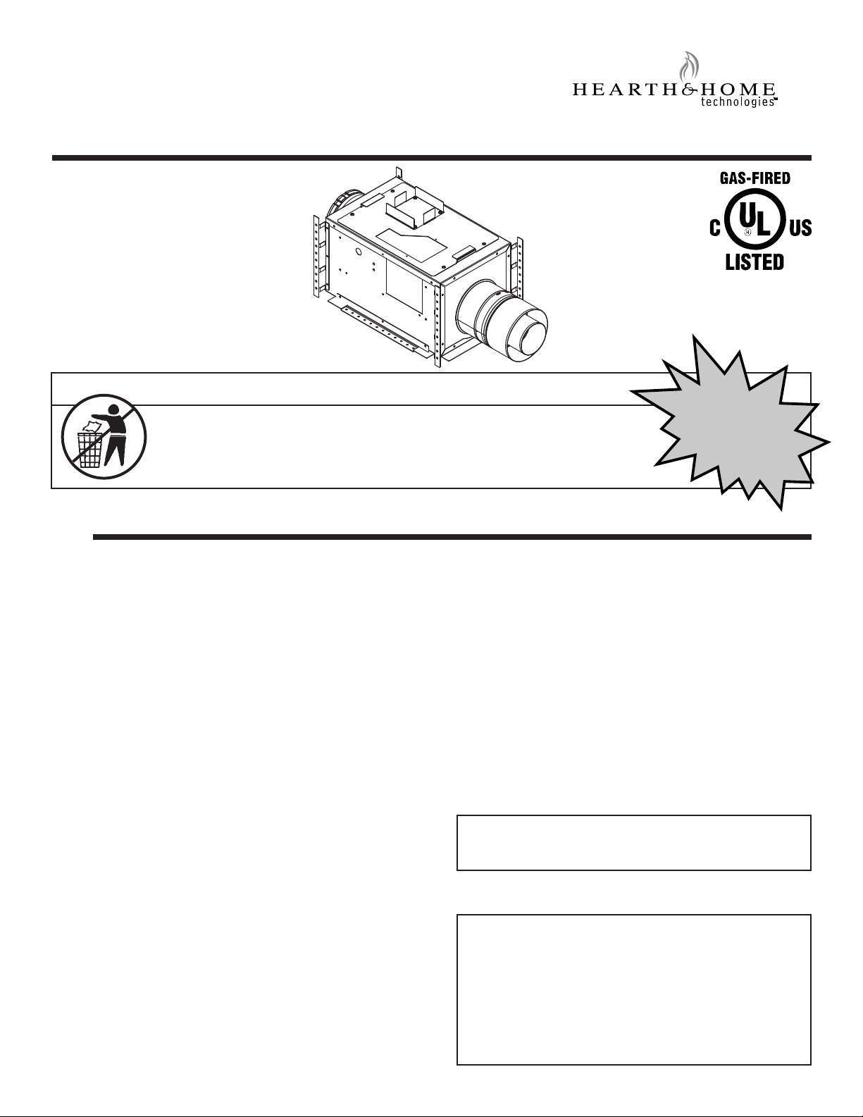
PVI-SLP
1
Power Vent Inline
- Installation Instructions -
NOTICE
DO NOT DISCARD THIS MANUAL
• Read, understand and follow
these instructions for safe
installation and operation.
1
• Important operating
and maintenance
instructions included.
Introduction
Table of Contents
1 Introduction
A. Components and Service Parts List . . . . . . . . . . . . . . . . . . 2
B. Installation of PVI-SLP . . . . . . . . . . . . . . . . . . . . . . . . . . . . 2
2 Vent Information and Diagrams
A. Installation of Vent Pipe. . . . . . . . . . . . . . . . . . . . . . . . . . . . 3
B. Vent/Pipe Regulations . . . . . . . . . . . . . . . . . . . . . . . . . . . . . 3
C. Venting Length - Model Categories and Length
Requirements by Termination Type . . . . . . . . . . . . . . . . . 10
D. Vent Termination Minimum Clearances . . . . . . . . . . . . . . 12
3 Framing and Clearances
A. Framing and Clearances . . . . . . . . . . . . . . . . . . . . . . . . . . 13
4 Electrical Information
A. Wiring the Appliance for the PVI-SLP . . . . . . . . . . . . . . . . 17
DO NOT
DISCARD
• Leave this manual with
party responsible for use
and operation.
IMPORTANT: Failure to read and follow these instruc-
tions may create a possible hazard and will void the fi re-
place warranty.
These instructions must remain with the equipment.
CAUTION! Risk of Cuts or Abrasions. Wear protective
gloves and safety glasses during installation. Sheet metal
edges are sharp.
INTRODUCTION
The Power Vent Inline (PVI-SLP) is certifi ed for use only on
fi replaces manufactured by Hearth & Home Technologies
with IPI (intermittent pilot ignition) gas controls and is for use
only on top-vented applications. Fireplaces equipped with
millivolt type gas controls CANNOT use this product.
Note: The battery back-up feature of the IPI system is removed
when the PVI-SLP power vent is installed. The fi replace may
no longer be operated with battery back-up.
5 Operating Instructions
A. Installation Inspection . . . . . . . . . . . . . . . . . . . . . . . . . . . . 23
B. Vacuum Switch Orientation . . . . . . . . . . . . . . . . . . . . . . . . 23
C. Setting the PVI-SLP Baffl e Adjustment . . . . . . . . . . . . . . . 23
D. Operating Instructions . . . . . . . . . . . . . . . . . . . . . . . . . . . . 24
E. Maintenance . . . . . . . . . . . . . . . . . . . . . . . . . . . . . . . . . . . 24
F. PVI-SLP Troubleshooting . . . . . . . . . . . . . . . . . . . . . . . . . 25
Installation of the PVI-SLP may be done by a qualifi ed
service technician only. Installation MUST comply with local, regional, state and national codes and regulations.
1
Hearth & Home Technologies • Power Vent Inline (PVI-SLP) Instructions • 2196-900 Rev. AC • 12/15
The PVI-SLP operates on 120VAC, 60Hz electrical service
which is supplied at the fi replace junction box.
IMPORTANT OPERATIONAL NOTE: When the control
being used to run the fi replace is activated, a 120 second
delay will occur before ignition occurs. This is to allow a
pre-purge by the PVI-SLP. If fi replace does not light after
135 seconds, refer to the Troubleshooting section of this
instruction for further direction. If an RC100, RC200 or
RC300 remote is being used, there will also be a 20 minute
post-purge in which the PVI-SLP will continue to run after
appliance is turned off.
Page 2
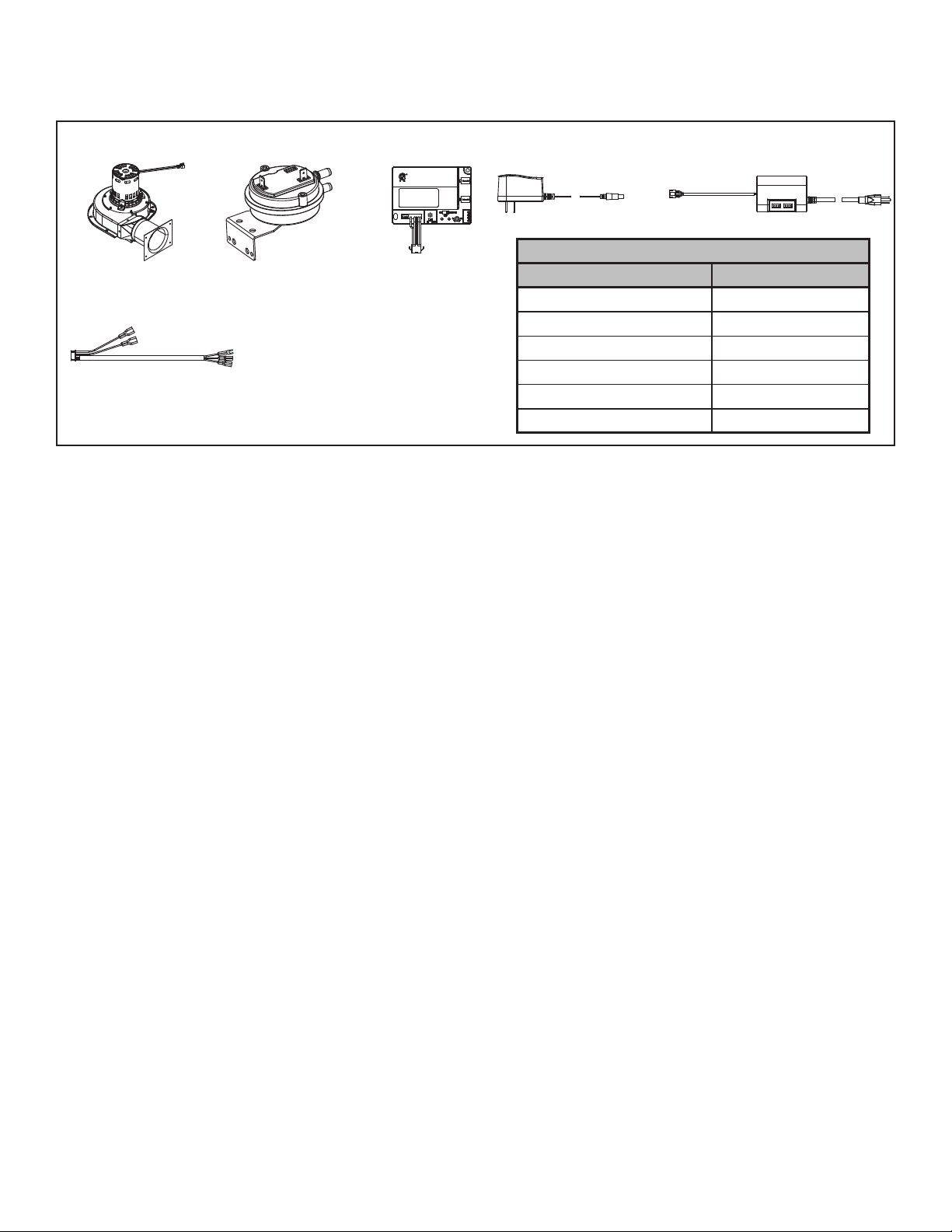
A. Components and Service Parts List
Service Parts List
Replacement parts can be obtained from your dealer. Repair of the Power Vent should only be done by a qualifi ed service technician.
BLOWER ASSEMBLY
2196-025
8K1-PVI
WIRE HARNESS
2196-200
NOTE: Wire Harness connecting PVI to appliance sold separately.
The length of wire harness needed varies by installation.
Figure 1.1 Service Parts
VACUUM SWITCH
2196-326
8K1-PVI
2196-150
6VDC POWER RECEPTACLE
2326-131
Required Wire Harness
Lengths Available Part Number
10 ft. PV Wire Harness PVI-WH10
20 ft. PV Wire Harness PVI-WH20
40 ft. PV Wire Harness PVI-WH40
60 ft. PV Wire Harness PVI-WH60
80 ft. PV Wire Harness PVI-WH80
100 ft. PV Wire Harness PVI-WH100
AUX300
MODULE
2166-335
AUX 2
AUX 1
B. Installation of PVI-SLP
1. INSTALLATION PRECAUTIONS
a. This device must be installed by a qualifi ed installer
in accordance with these instructions.
b. Safety inspection of the venting system should
be performed before and after installation of this
power vent. Consult local code offi cials and follow
applicable installation codes.
c. DO NOT INSTALL DAMAGED EQUIPMENT OR
VENT COMPONENTS.
d. Disconnect electrical power supply before making
wiring connections.
e. Venting of more than one appliance in a common
vent system is prohibited.
f. Clearances between the vent pipe and combustible
materials must be maintained at 1-1/2-inch top,
1-inch sides and bottom.
g. All outer pipe joints must be sealed with high tem-
perature silicone. See Section 2.A.
h. The access panel opening must be located such
that access for service and adjustment is available.
The NEC requires a minimum of 30 inches of space
around the opening and 36 inches in front of the
opening to the access panel. Consult offi cials hav-
ing jurisdiction regarding regional requirements.
CAUTION! Failure to install, operate, and maintain the
power venting system in accordance with manufacturer's
instructions will result in conditions which may produce
bodily injury and/or property damage.
NOTICE: The blower motors present in this powervent
will generate sound during operation. The effects of the
increased sound level can be minimized with careful
planning during installation of the system. Locating the
powervent service access grill in an area remote of immediate living space will reduce the effects of the added
sound generated during operation.
2
Hearth & Home Technologies • Power Vent Inline (PVI-SLP) Instructions • 2196-900 Rev. AC • 12/15
2. INSTALLATION GUIDELINES
WARNING: RISK OF FIRE AND BURNS. DO NOT
install PVI-SLP with the access panel facing upward.
Overheating may occur.
NOTICE: Installation of the PVI-SLP in an attic is not
recommended in regions where temperatures reach 0°F
(-18°C) and relative humidity exceeds 60% simultaneously.
Low temperatures and high moisture content may cause
the PVI-SLP to freeze.
a. If the PVI-SLP is being installed in a confi ned space
(such as a utility closet, mechanical room or attic space)
with a total volume less than 250 cubic feet, an access
hole with minimum dimensions of 8 inches by 16 inches
will be required directly in front of the access panel.
The recommended access hole size is 12 inches by 17
inches. This size will allow full access to the 11 inch x
16 inch access panel on the PVI-SLP. See Figure 3.1.
The confi ned space where the PVI is installed, and the
space to which the access hole opens, must add up to
at least 250 cubic feet. This hole may be covered with
a decorative cover as long as the cover has a minimum
of 50% open air. If the PVI-SLP is being installed in a
space greater than 250 cubic feet the access hole is still
required, but a solid cover may be used. This also applies
to a fi replace chase.
The decorative cover CANNOT be located on an outside
wall that is open to the environment.
b. For installations near loose-fi ll insulation (such as attics)
a minimum clearance of six inches must be maintained
between the access panel and the insulation.
c. The PVI-SLP CANNOT be installed with the access
panel facing upward.
d. The exit termination of mechanical draft systems shall
not be less than seven feet above grade when located
adjacent to public walkways.
e. A mechanical drafting venting system shall terminate at least
three feet above any forced air inlet located within 10 feet.
Page 3
2
2
Vent Information and Diagrams
A. Installation of Vent Pipe
For information on standard procedures for venting the
appliance, refer to the "Vent Information and Diagrams"
section of the appliance installation manual.
For the allowable pipe lengths and elbow combinations
for an appliance utilizing the PVI-SLP, consult the Power
Vent diagrams in the Vent Information and Diagrams section of the appliance installation manual. The PVI-SLP
uses SLP pipe (6-5/8 inch) connections for both the inlet
and outlet.
The following termination caps are available for use with
the power vent inline (PVI-SLP): SLP-TVHW, SLP-LPC,
SLP-TRAP, SLP-HHW2, SLP-HRC-SS, SLP-HRC-ZCSS, SLP-TB1. Check installation manual for termination
caps specifi cations.
In certain cases, a pipe adapter may be used in the vent
run. The DVP-2SL adapts from 5 in. / 8 in. DVP series
starting collars to 4 in. / 6-5/8 in. SLP series vent pipe.
Either SLP or DVP venting may be used throughout the
vent run except on certain models that require DVP pipe.
See Table 2.1. Refer to Section 2.B for more information
regarding venting regulations.
B. Vent/Pipe Regulations
WARNING! Risk of Fire!
Maintain minimum pipe length between appliance and
PVI-SLP on all models. Combustible materials surrounding
pipe may overheat.
1. A minimum length of venting is required between the
appliance and the PVI-SLP. This minimum length requirement varies for the specifi c appliance. Refer to
Table 2.1. for requirements for specifi c models. Once
the minimum length requirement is met, the PVI-SLP
may be installed at any location within the vent run
confi guration.
2. A minimum of 18 inches is required between the PVISLP and the termination cap to allow room for the pipe
to go through a wall or roof.
3. If PVI-SLP is installed in the vertical position, a minimum
of two 90 degree elbows and two feet of pipe is required
between the appliance and the PVI-SLP.
4. Total allowable length decreases by 2 ft. for every 1 ft.
of vertical drop.
Note: See Table 2.1 for model specifi c vent requirements.
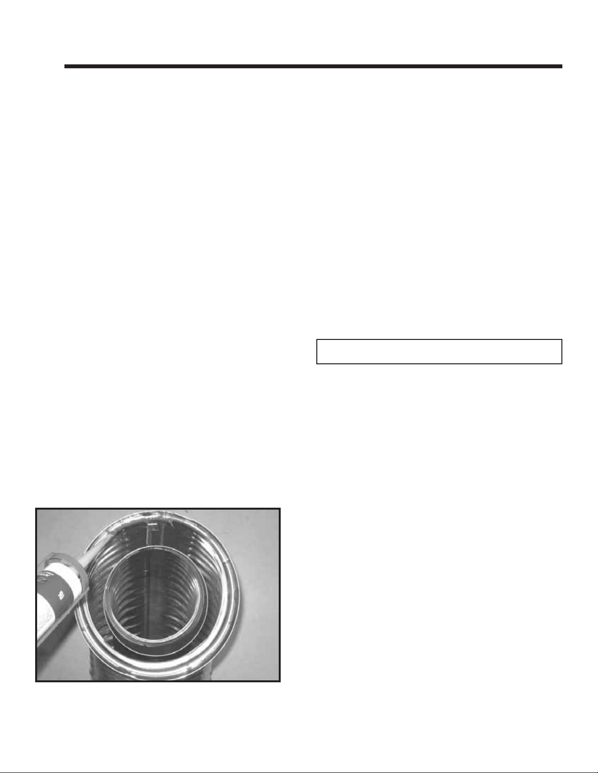
SLP pipe may be used on the termination side of the PVI.
All outer pipe joints must be sealed with high temperature
silicone (with a minimum of 300ºF continuous exposure
rating), including the slip section that connects directly to
the horizontal termination cap.
• Apply a bead of silicone sealant inside the female outer
pipe joint prior to joining sections. See Figure 2.1.
• Only outer pipes need to be sealed. All unit collar, pipe,
slip section, elbow and cap outer fl ues shall be sealed
in this manner, unless otherwise stated.
Figure 2.1 High Temperature Silicone Sealant
3
Hearth & Home Technologies • Power Vent Inline (PVI-SLP) Instructions • 2196-900 Rev. AC • 12/15
Page 4
B. Vent/Pipe Regulations (continued)
WARNING! Risk of Fire!
• PVI-SLP cannot be installed directly on appliance. The PVI-SLP and combustible materials surrounding vent pipe may
overheat.
• A minimum length run of initial vent pipe is required between the appliance and the inlet of the PVI-SLP. The initial
minimum vent run requirement varies depending on the specifi c appliance and its venting confi guration.
• Some models require DVP Series pipe for the initial minimum vent section directly off the appliance.
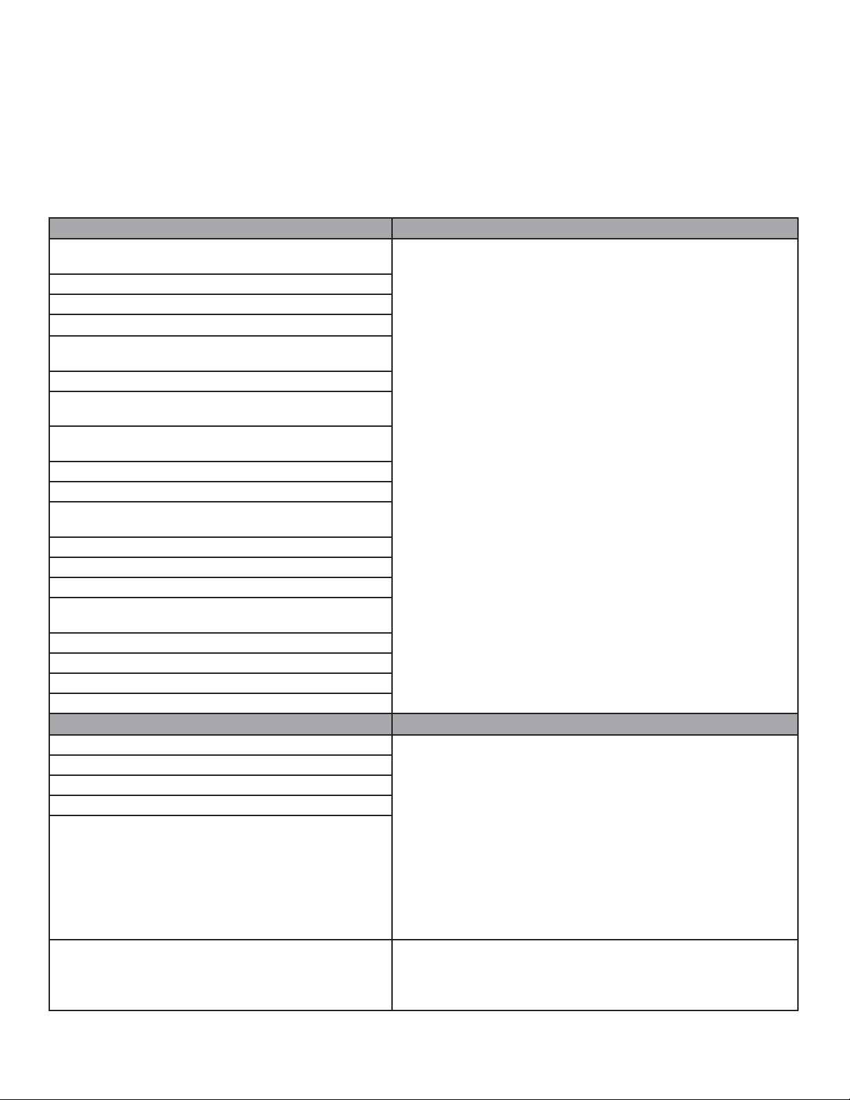
MODEL MINIMUM VENTING BETWEEN APPLIANCE AND PVI-SLP
6000C, 6000CL, 6000CLX,
8000C, 8000CL, 8000CLX 6000BEC
6000CMOD, 8000CMOD
CD4236, CD4842
CNXT4236, CNXT4842
CRAVE4836, CRAVE4836ST, CRAVE6048, CRAVE6048ST
CRAVE7260, CRAVE7260ST, CRAVE8472, CRAVE8472ST
DV3732SBI
GDST3831, GDST4336, GDFL4136, GDCR4136,
GDCL4136
MEZZO36, MEZZO36ST, MEZZO48, MEZZO48ST
MEZZO60, MEZZO60ST, MEZZO72, MEZZO72ST
NDV3630, NDV3933, NDV4236, NDV4842
NEVO3630, NEVO4236
ST-36TR. ST-36TR, ST-36TRB, PIERI-36TR, PIER-36TRB,
LCOR-36TRB, RCOR-36TRB
RED40, RED40ST
REVO-S21, REVO-H31
SLR32, RAVE3012I
SLR-B, SLR-C,
RAVE 4013I, RAVE4013I-C
SL-350TRS, SL-550TRS, SL-750STRS
SL-550TR, SL-750TR, SL-950TR
SL-550METRO, SL-550-BE-M
ST-550T, ST-550TM
MODEL MINIMUM VENTING BETWEEN APPLIANCE AND PVI-SLP
ESC-42ST
ESCAPE-36DV, ESCAPE42DV
HEIR36, HEIR42, HEIR50
LUX36, LUX42
PVI installed horizontal orientation: One 90 degree elbow and
a total of two feet of straight horizontal or straight vertical SLP
pipe. See Figure 2.2 and Figure 2.5.
PVI installed vertical orientation: Two 90 degree elbows and
a total of two feet straight horizontal or straight vertical SLP pipe.
See Figure 2.3, 2.4, 2.6.
PVI installed horizontal orientation: Minimum two feet straight
vertical DVP pipe directly off appliance followed by 90 degree
elbow and two feet DVP pipe. PVI-SLP adapter must be located
directly between initial DVP pipe and PVI-SLP. See Figure 2.2
and Figure 2.5.
TRUE-36, TRUE-42, TRUE-50
CERONA-36, CERONA-42
PRIMO48, PRIMO48ST, PRIMO60, PRIMO60ST,
PRIMO72, PRIMO72ST
Table 2.1
4
Hearth & Home Technologies • Power Vent Inline (PVI-SLP) Instructions • 2196-900 Rev. AC • 12/15
PVI installed vertical orientation: Minimum two feet straight
vertical DVP pipe directly off appliance, followed by two 90
degree elbows and a total of two feet straight horizontal or
straight vertical DVP pipe. PVI-SLP adapter must be located
directly between initial DVP pipe and PVI-SLP. See Figure 2.3,
Figure 2.4, Figure 2.6.
PVI installed vertical or horizontal orientation: Minimum three
feet of DVP or SLP pipe is required before connecting the PVISLP system. The 3 foot minimum does not include the factoryinstalled six inch DVP pipe.
Page 5
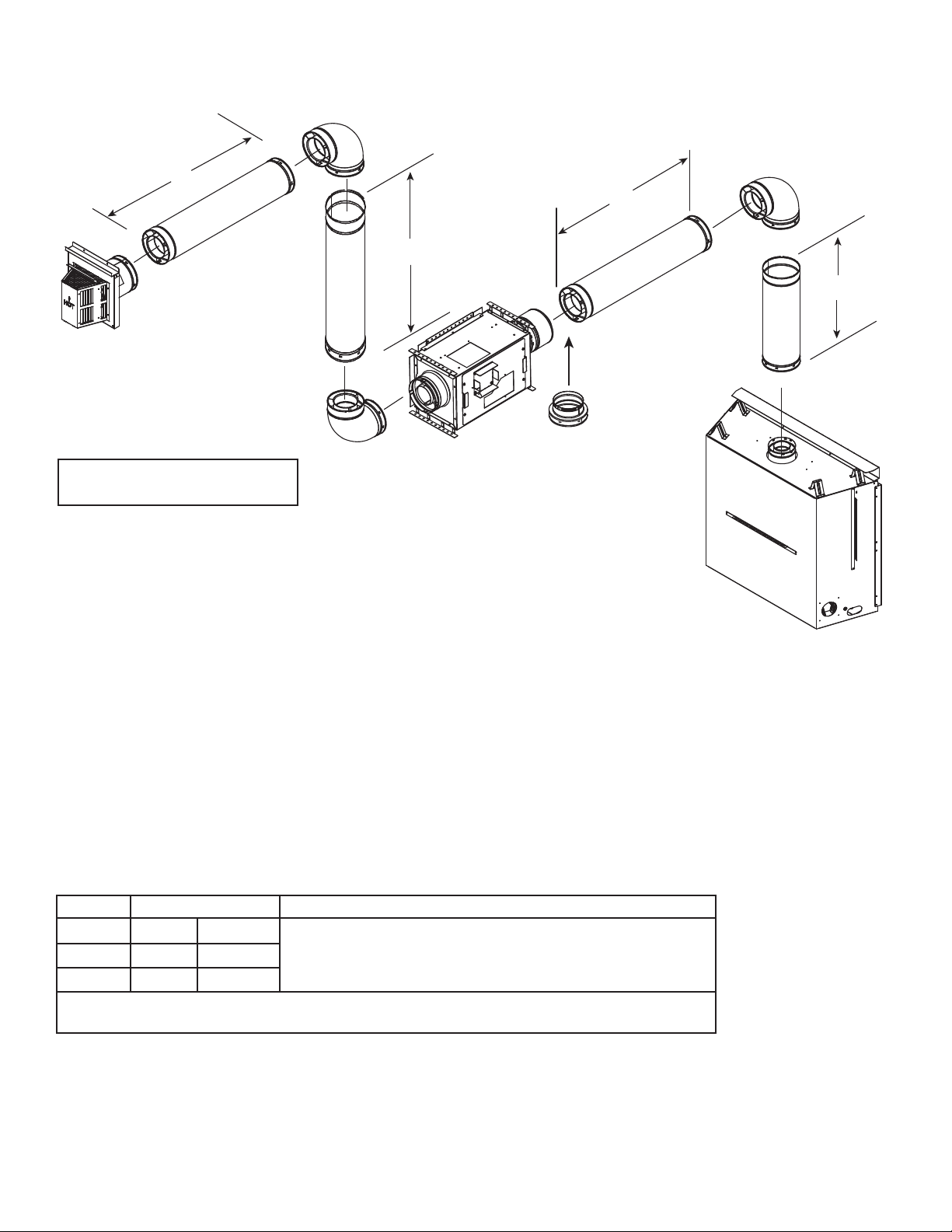
Top Vent - Horizontal Termination
H
2
Note: 1 ft. of vertical drop decreases
total allowable length by 2 ft.
H
1
V
2
V
1
A DVP-2SL ADAPTER
is required in this position
in the vent run on certain
models. See Table 2.1.
WARNING! Risk of Fire! Use DVP pipe between appliance and PVI-SLP on these models:
ESCAPE-42DV, ESCAPE-36DV, ESC-42ST, HEIR36, HEIR42, HEIR50, LUX36, LUX42,
TRUE-36, TRUE-42, TRUE-50, CERONA-36, CERONA-42, MEZZO36, MEZZO36ST,
CRAVE4836, CRAVE4836ST, MEZZO48, MEZZO48ST, CRAVE6048, CRAVE6048ST,
MEZZO60, MEZZO60ST, CRAVE7260, CRAVE7260ST, MEZZO72, MEZZO72ST,
CRAVE8472, CRAVE8472ST
Combustibles surrounding pipe may overheat.
Note: For PRIMO models, see the PRIMO Installation Manual for vent confi gurations.
Minimum Maximum
H
+ V
1
H
2
V
2
A minimum of 2 ft. of vertical piping is required between the appliance and the PVI-SLP in addition to the
minimum venting described above when installing PVI-SLP with certain appliance models. See Table 2.1.
Figure 2.2 Horizontal PVI Orientation
24 in. 610 mm
1
18 in. 457 mm
0 in. 0 mm
See Chart in Section 2.C: "Venting Length - Model Categories and
Length Requirements by Termination Type."
5
Hearth & Home Technologies • Power Vent Inline (PVI-SLP) Instructions • 2196-900 Rev. AC • 12/15
Page 6
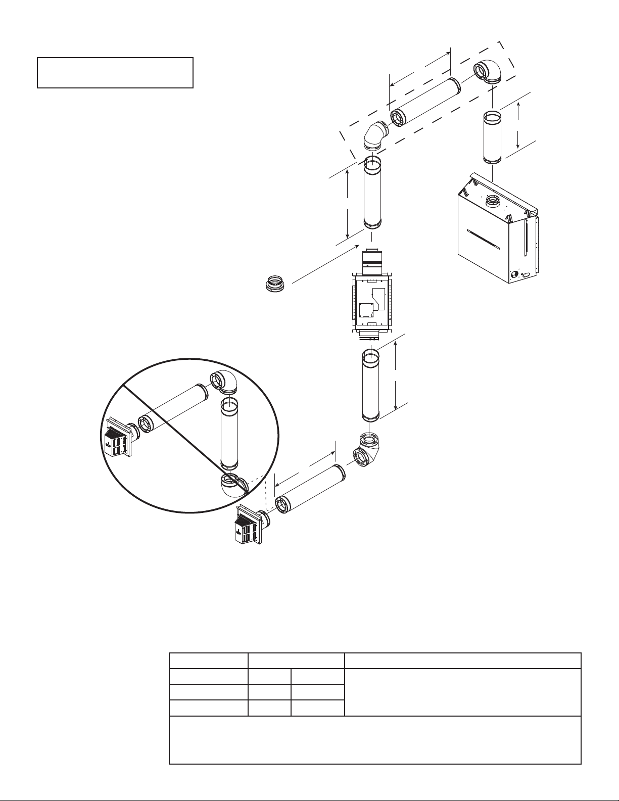
Note: 1 ft. of vertical drop decreases
total allowable length by 2 ft.
WARNING! Risk of Overheating!
- Minimum inital length of vent pipe required between
appliance and vertically positioned PVI-SLP.
- Must include two 90 degree elbows.
NOTICE: If pipe configuration includes a vertical component that goes
downward, a vertical component going back upward is not allowed.
A DVP-2SL ADAPTER
is required in this position
in the vent run on certain
models. See Table 2.1.
H
1
V
1
V
2
V
3
H
2
WARNING! Risk of Fire! Use DVP pipe between appliance and PVI-SLP on these models:
ESCAPE-42DV, ESCAPE-36DV, ESC-42ST, HEIR36, HEIR42, HEIR50, LUX36, LUX42, TRUE-36, TRUE-42, TRUE50, CERONA-36, CERONA-42, MEZZO36, MEZZO36ST, CRAVE4836, CRAVE4836ST, MEZZO48, MEZZO48ST,
CRAVE6048, CRAVE6048ST, MEZZO60, MEZZO60ST, CRAVE7260, CRAVE7260ST, MEZZO72, MEZZO72ST,
CRAVE8472, CRAVE8472ST
Combustibles surrounding pipe may overheat.
Note: For PRIMO models, see the PRIMO Installation Manual for vent confi gurations.
Minimum Maximum
H
+ V1 + V2 24 in. 610 mm
Figure 2.3 Vertical PVI Orientation
6
Hearth & Home Technologies • Power Vent Inline (PVI-SLP) Instructions • 2196-900 Rev. AC • 12/15
1
H
2
V
3
18 in. 457 mm
0 in. 0 mm
A minimum of 2 ft. of vertical piping is required between the appliance and the PVI-SLP in addition
to the minimum venting described above when installing PVI-SLP with certain appliance models.
See Table 2.1. V minimum = 2 ft. and V2 + H1 + V1 minimum = 4 ft. for certain appliance models.
See Chart in Section 2.C: "Venting Length - Model Categories and Length Requirements by Termination Type."
See Table 2.1.
Page 7
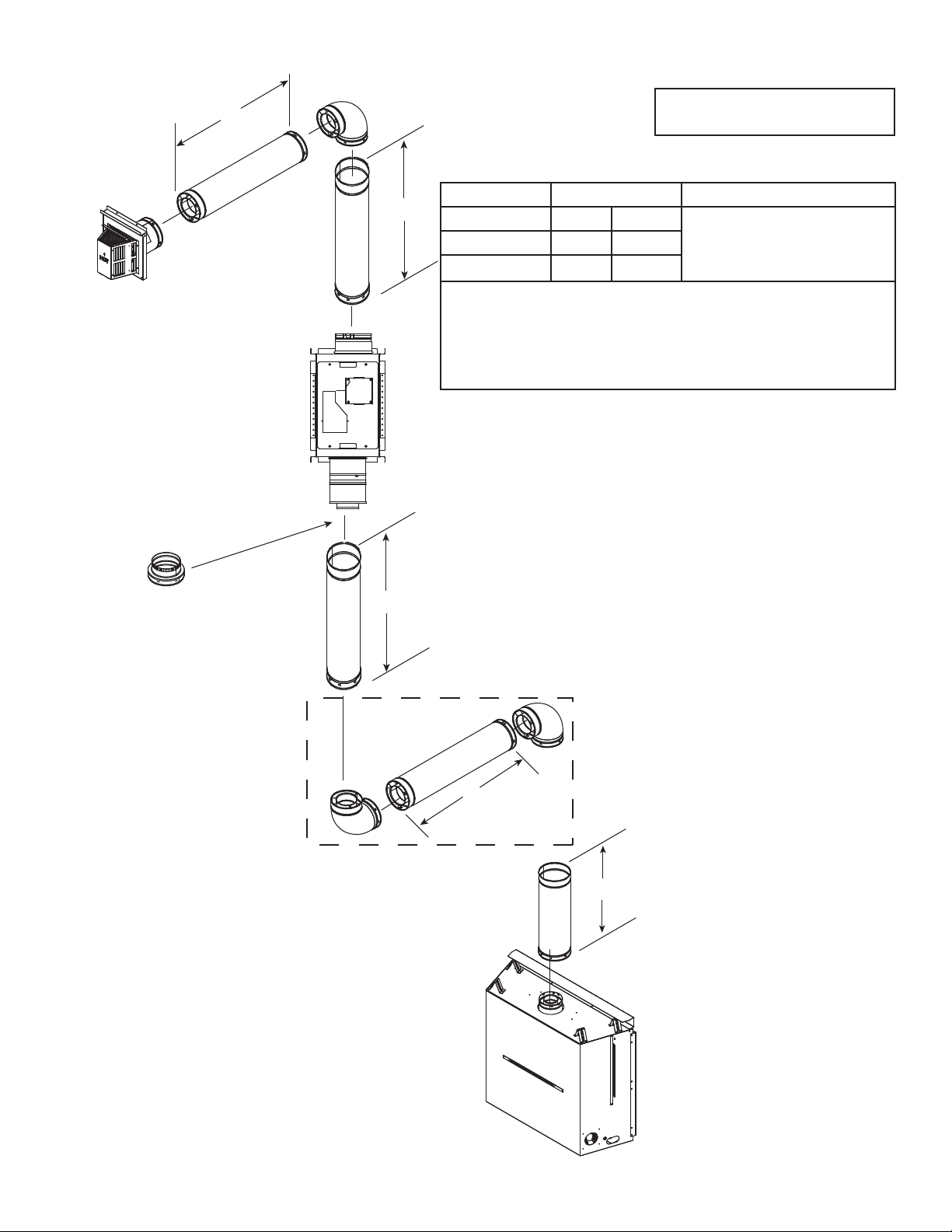
Top Vent - Horizontal Termination - (continued)
H
2
Note: 1 ft. of vertical drop decreases
total allowable length by 2 ft.
Minimum Maximum
V
3
H1 + V1 + V
V
3
H
2
24 in. 610 mm See Chart in Section 2.C: "Vent-
2
0 in. 0 mm
18 457 mm
ing Length - Model Categories
and Length Requirements by
Termination Type."
A minimum of 2ft. of vertical piping is required between the appliance
and the PVI-SLP in addition to the minimum venting described above
when installing PVI-SLP with certain appliance models. See Table 2.1.
V minimum = 2 ft. and V2 + H1 + V1 minimum = 4 ft. for certain appliance
models. See Table 2.1.
A DVP-2SL ADAPTER
is required in this position
V
2
in the vent run on certain
models. See Table 2.1.
WARNING! Risk of Fire! Use DVP pipe between appliance
and PVI-SLP on these models:
ESCAPE-42DV, ESCAPE-36DV, ESC-42ST, HEIR36,
HEIR42, HEIR50, LUX36, LUX42, TRUE-36, TRUE42, TRUE-50, CERONA-36, CERONA-42, MEZZO36,
MEZZO36ST, CRAVE4836, CRAVE4836ST, MEZZO48,
MEZZO48ST, CRAVE6048, CRAVE6048ST, MEZZO60,
MEZZO60ST, CRAVE7260, CRAVE7260ST, MEZZO72,
MEZZO72ST, CRAVE8472, CRAVE8472ST
Combustibles surrounding pipe may overheat.
WARNING! Risk of Overheating!
- Minimum inital length of vent pipe required between
appliance and vertically positioned PVI-SLP.
H
1
- Must include two 90 degree elbows.
V
1
Note: For PRIMO models, see the PRIMO Installation
Manual for vent confi gurations.
Figure 2.4 Vertical PVI Orientation
7
Hearth & Home Technologies • Power Vent Inline (PVI-SLP) Instructions • 2196-900 Rev. AC • 12/15
Page 8
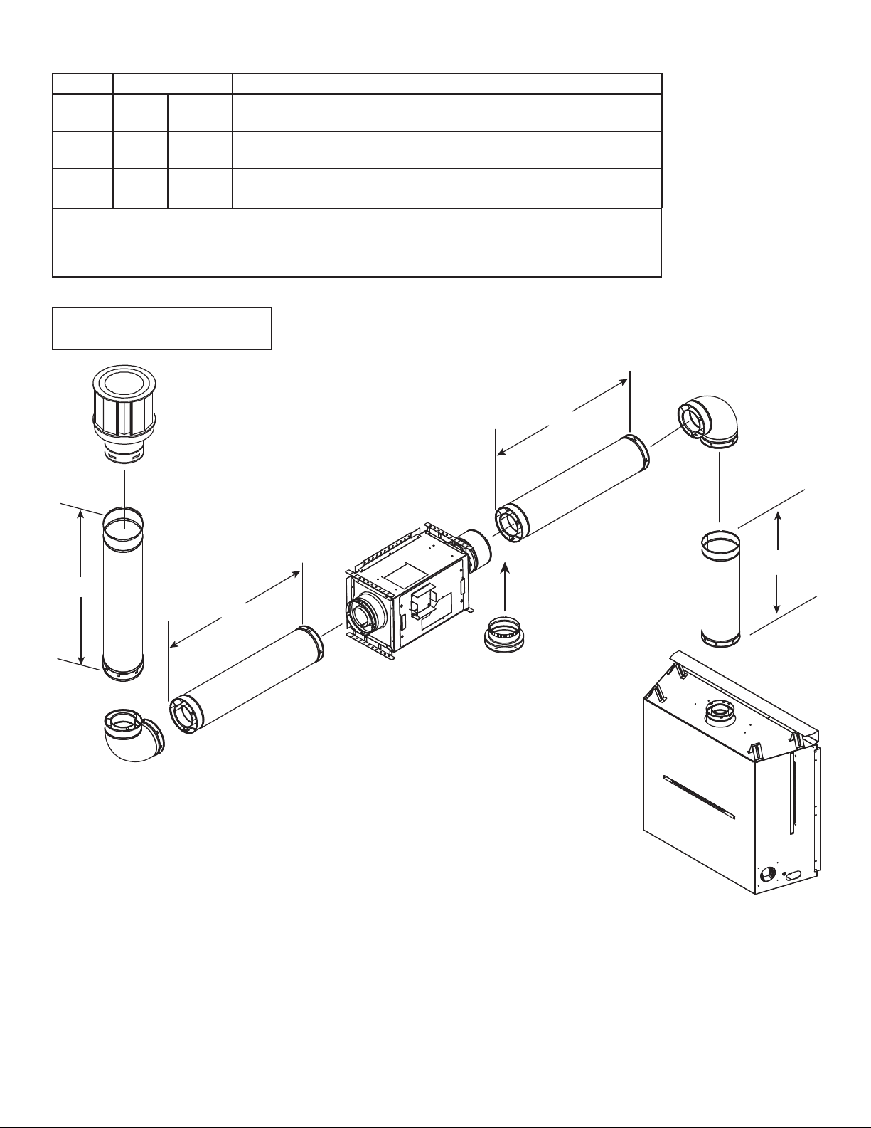
Top Vent - Vertical Termination
Minimum Maximum
+ V124 in. 610 mm See Chart in Section 2.C: "Venting Length - Model Categories and Length
H
1
V
H
TOTAL
A minimum of 2ft. of vertical piping is required between the appliance and the PVI-SLP in addition to the
minimum venting described above when installing PVI-SLP with certain appliance models. See Table 2.1.
18 in. 457 mm See Chart in Section 2.C: "Venting Length - Model Categories and Length
2
00
Requirements by Termination Type."
Requirements by Termination Type."
30% of total vent length allowed in chart: "Venting Length - Model Categories
and Length Requirements by Termination Type" in Section 2.C.
V minimum = 2 ft. and H
Note: 1 ft. of vertical drop decreases
total allowable length by 2 ft.
V
2
+ V1 minimum = 4 ft. with certain appliance models. See Table 2.1.
1
H
2
H
1
A DVP-2SL ADAPTER
is required in this position
in the vent run on certain
models. See Table 2.1.
V
1
WARNING! Risk of Fire! Use DVP pipe between appliance and PVI-SLP on these models:
ESCAPE-42DV, ESCAPE-36DV, ESC-42ST, HEIR36, HEIR42, HEIR50, LUX36, LUX42,
TRUE-36, TRUE-42, TRUE-50, CERONA-36, CERONA-42, MEZZO36, MEZZO36ST,
CRAVE4836, CRAVE4836ST, MEZZO48, MEZZO48ST, CRAVE6048, CRAVE6048ST,
MEZZO60, MEZZO60ST, CRAVE7260, CRAVE7260ST, MEZZO72, MEZZO72ST,
CRAVE8472, CRAVE8472ST
Combustibles surrounding pipe may overheat.
Note: For PRIMO models, see the PRIMO Installation Manual for vent confi gurations.
Figure 2.5 Horizontal PVI-SLP Orientation
8
Hearth & Home Technologies • Power Vent Inline (PVI-SLP) Instructions • 2196-900 Rev. AC • 12/15
Page 9

Top Vent - Vertical Termination - (continued)
+ V1 + V224 in. 610 mm See Chart in Section 2.C: "Venting Length - Model
H
1
V
V
3
3
H
TOTAL
A minimum of 2ft. of vertical piping is required between the appliance and the PVISLP in addition to the minimum venting described above when installing PVI-SLP with
certain appliance models. See Table 2.1.
Minimum Maximum
Categories and Length Requirements by Termination Type."
18 in. 457 mm See Chart in Section 2.C: "Venting Length - Model
Categories and Length Requirements by Termination Type."
0 in. 0 in. 30% of total vent length allowed in chart: "Venting
Length - Model Categories and Length Requirements by Termination Type" in Section 2.C.
H
2
A DVP-2SL ADAPTER
is required in this position
in the vent run on certain
models. See Table 2.1.
V minimum = 2 ft. and v2 + H1 + V1 minimum = 4 ft. for certain appliance models. See
Table 2.1.
WARNING! Risk of Fire! Use DVP pipe between appliance and PVI-SLP
on these models:
ESCAPE-42DV, ESCAPE-36DV, ESC-42ST, HEIR36, HEIR42, HEIR50,
LUX36, LUX42, TRUE-36, TRUE-42, TRUE-50, CERONA-36, CERONA-42, MEZZO36, MEZZO36ST, CRAVE4836, CRAVE4836ST,
MEZZO48, MEZZO48ST, CRAVE6048, CRAVE6048ST, MEZZO60,
MEZZO60ST, CRAVE7260, CRAVE7260ST, MEZZO72, MEZZO72ST,
CRAVE8472, CRAVE8472ST
Combustibles surrounding pipe may overheat.
Note: For PRIMO models, see the PRIMO Installation Manual for vent
V
2
confi gurations.
WARNING! Risk of Overheating!
- Minimum inital length of vent pipe required between
appliance and vertically positioned PVI-SLP.
- Must include two 90 degree elbows.
Figure 2.6 Vertical PVI-SLP Orientation
9
Hearth & Home Technologies • Power Vent Inline (PVI-SLP) Instructions • 2196-900 Rev. AC • 12/15
H
1
V
1
Page 10

C. Venting Length - Model Categories and Length Requirements by Termination Type
The Model Category (0,1, 2 or 3) in Table 2.2 corresponds with the number in the shaded area of the Vent Length Requirement
Chart In Tables 2.3 and 2.4.
Note: For PRIMO models, see the PRIMO Installation Manual for vent confi gurations.
HEAT & GLO HEATILATOR
Category 0
REVO-S21 ST-550T
REVO-H31 ST-550TM SL-350TRS, SL-550TRS, SL-
Category
0 &1
SLR32 6000C, 6000CL, 6000CLX,
Category 0, 1 & 2
SL-550TR, SL-750TR, SL950TR
750TRS
6000BEC
8000C, 8000CL, 8000CLX ESCAPE-36DV NEVO3630, NEVO4236
6000CMOD, 8000CMOD ESCAPE-42DV DV3732SBI
SL-550METRO, SL-550BE-M
ST-36TR,ST-36TRB,PIER36TR, PIER-36TRB, LCOR36TRB,RCOR-36TRB
MEZZO60, MEZZO60ST
MEZZO72, MEZZO72ST
MEZZO36, MEZZO36ST,
MEZZO48, MEZZO48ST
Category 0,1, 2
& 3
SLR-B, SLR-C RAVE3012I
RED40, RED40ST
ESC-42ST
TRUE-36, HEIR36
TRUE-42, HEIR42
TRUE-50, HEIR50
LUX36, LUX42
CERONA-36
CERONA-42
Category
0, 1
Category 0, 1 & 2
NDV3630, NDV3933,
NDV4236, NDV4842
CD4236, CD4842
CNXT4236, CNXT4842
GDST3831, GDST4336,
GDFL4136, GDCR4136,
GDCL4136
CRAVE4836,
CRAVE4836ST
CRAVE6048,
CRAVE6048ST
CRAVE7260,
CRAVE7260ST,
CRAVE8472,
CRAVE8472ST
Category 0, 1,
2 & 3
RAVE4013i
RAVE4013i-C
Table 2.2 Models
Note: The REVO-V12 is not approved for use with the PVI-SLP.
Horizontal Termination
Total Venting Length (Feet) Includes both horizontal and vertical section of pipe
# of Elbows 10 20 30 40 50 60 70 80 90 100 110 120 130 140
1 00000111123
2 0000011123
3 000011112
4 000011123
5 00011112
6 00011123
7 00111123
8 0011112
9 0111112
10 0111123
11 111112
12 111112
Table 2.3 Allowable Vent Runs - Horizontal Termination
10
Hearth & Home Technologies • Power Vent Inline (PVI-SLP) Instructions • 2196-900 Rev. AC • 12/15
Page 11

Vertical Termination
Total Venting Length (feet) Includes both horizontal and vertical section of pipe
# of Elbows 10 20 30 40 50 60 70 80 90 100 110 120 130 140
1 00000111111111
2 0000011111111
3 000011111111
4 000011111111
5 00011111111
6 0001111111
7 0011111111
8 001111111
9 011111111
10 01111111
11 11111111
12 1111111
Table 2.4 Allowable Vent Runs - Vertical Termination
11
Hearth & Home Technologies • Power Vent Inline (PVI-SLP) Instructions • 2196-900 Rev. AC • 12/15
Page 12

D. Vent Termination Minimum Clearances
WARNING
Fire Risk.
Maintain vent clearance to combustibles as
specifi ed.
• DO NOT pack air space with insulation or other
materials.
Failure to keep insulation or other materials away
from vent pipe may cause overheating and fi re.
Refer to the appliance installation manual for information
on minimum clearances for vent termination.
HORIZONTAL
OVERHANG
6 in. (minimum) up to 20 in.
AB
152 mm/508 mm
20 in. and over 0 in. minimum
B
Gas
Termination
Cap **
18 in. minimum
457 mm
Gas, Wood or Fuel Oil
Termination Cap
A *
2 FT.
MIN.
GAS DIRECT VENT
TERMINATION CAP
20 INCHES MIN.
LOWEST
DISCHARGE
OPENING
H (MIN.) - MINIMUM HEIGHT FROM ROOF
TO LOWEST DISCHARGE OPENING
X
12
ROOF PITCH
IS X/ 12
VERTICAL
WALL
Roof Pitch H (Min.) Ft.
Flat to 6/12...........................................................1.0*
Over 6/12 to 7/12 .................................................1.25*
Over 7/12 to 8/12 .................................................1.5*
Over 8/12 to 9/12 .................................................2.0*
Over 9/12 to 10/12 ...............................................2.5*
Over 10/12 to 11/12 .............................................3.25
Over 11/12 to 12/12 .............................................4.0
Over 12/12 to 14/12 .............................................5.0
Over 14/12 to 16/12 .............................................6.0
Over 16/12 to 18/12 .............................................7.0
Over 18/12 to 20/12 .............................................7.5
Over 20/12 to 21/12 .............................................8.0
* 3 foot minimum in snow regions
Figure 2.8 Minimum Height From Roof To Lowest Discharge
Opening
If using decorative cap cover(s), this distance may need to be
*
increased. Refer to the installation instructions supplied with the
decorative cap cover.
In a staggered installation with both gas and wood or fuel oil
**
terminations, the wood or fuel oil termination cap must be
higher than the gas termination cap.
Figure 2.9 Staggered Termination Caps
12
Hearth & Home Technologies • Power Vent Inline (PVI-SLP) Instructions • 2196-900 Rev. AC • 12/15
Page 13

3
3
Framing and Clearances
A. Framing and Clearances
Note: The factory-installed mounting brackets must be used
to install the PVI-SLP securely to adjacent structures.
Chassis Dimensions
The dimensions are measured as shown in Figure 3.1.
Framing Dimensions
WARNING! Risk of fi re and burns! DO NOT install PVI-
SLP with the access panel facing upward. Overheating
may occur.
Table 3.1 and Figure 3.1 show the clearances required for
the PVI-SLP. Required clearances are the same for all
allowable PVI-SLP orientations.
Height Width Depth
20-7/8 in. 13-5/8 in. 12 in.
Table 3.1.
If the PVI-SLP is being installed in a confi ned space (such
as a utility closet, mechanical room or attic space) with
a total volume less than 250 cubic feet, an access hole
with minimum dimensions of 8 inches by 16 inches will be
required directly in front of the access panel. The recommended access hole size is 12 inches by 17 inches. This
size will allow full access to the 11 inch x 16 inch cover
on the PVI-SLP. The confi ned space where the PVI is
installed, and the space to which the access hole opens,
must add up to at least 250 cubic feet. This hole may be
covered with a decorative cover as long as the cover has a
minimum of 30% open air. If the PVI-SLP is being installed
in a space greater than 250 cubic feet the minimum size
access hole is still required, but a solid cover may be used.
This also applies to a fi replace chase. See Figure 3.2.
If the PVI-SLP is being installed in a space greater than 250
cubic feet, the minimum size access hole is still required,
but a solid cover may be used.
The access panel opening must be located such that access for service and adjustment is available. The NEC
requires a minimum of 30 inches of space around the
opening and 36 inches in front of the opening to the access panel. Consult offi cials having jurisdiction regarding
regional requirements.
8 IN. MIN.
16 IN. MIN.
TOP
= OPTIONAL FINISH MATERIAL AROUND ACCESS PANEL
Figure 3.2 Access Panel Framing Dimensions
1 IN. MIN. CLEARANCE
FRAMING WIDTH 13-5/8 IN.
32 IN. MIN.
35 IN. MAX.
Figure 3.1 Dimensions and Minimum Clearances
13
11-5/8 IN.
13-5/8 IN.
CLEARANCE
Hearth & Home Technologies • Power Vent Inline (PVI-SLP) Instructions • 2196-900 Rev. AC • 12/15
TOP
1 IN. MIN.
5-3/4 IN.
18-7/8 IN.
FRAMING HEIGHT
20-7/8 IN.
7-7/8 IN.
4-11/16 IN.
11 IN.
10-3/4 IN.
SIDE
16 IN.
1-7/16 IN.
ACCESS PANEL
5-7/8 IN.
Page 14

8 IN. MIN.
CENTER AIR
OPENING OVER
ACCESS PANEL
Note: A framed hole with mini-
mum dimensions of 8 inches x
16 inches is required in front of
the access panel.
This hole may be covered with
an open air louvered cover. The
recommended access hole size
is 12 inches by 17 inches. This
size will allow full access to the
11 inch x 16 inch access panel
on the PVI-SLP.
16 IN. MIN.
TOP
= OPTIONAL FINISH MATERIAL AROUND ACCESS PANEL
Figure 3.3 Access Panel Framing Dimensions
Figures 3.4 - 3.6 show possible framing techniques.
ACCESS PANEL
Figure 3.5 PVI-SLP Mounted to Vertical Surface
ACCESS PANEL
Note: An 8 X 16 inch (minimum dimensions) framed hole is required in
front of the access panel. This hole may be covered with an open air
louvered cover. The recommended access hole size is 12 inches by 17
inches. This size will allow full access to the 11 inch x 16 inch access
panel on the PVI-SLP.
ACCESS PANEL
WARNING! Risk of fire and burns! DO NOT install PVI-SLP with
the access panel facing upward. Overheating may occur.
Figure 3.4 PVI-SLP Mounted to Horizontal Surface
14
Hearth & Home Technologies • Power Vent Inline (PVI-SLP) Instructions • 2196-900 Rev. AC • 12/15
Note: A framed hole is
required in front of the
access panel.
This hole may be covered
with an open air louvered
cover and must be a minimum of 8 inches x 16
inches.
The recommended access
hole size is 12 inches by 17
inches. This size will allow
full access to the 11 inch x
16 inch access panel on the
PVI-SLP.
APPLIANCE
Figure 3.6 Mount PVI-SLP to Chase
CHASE
Page 15

Refer to Figures 3.7, 3.8 and 3.9 for installation
requirements depending on orientation of the PVI-SLP.
ADJUST BRACKET
TO SPECIFIED DEPTH
1-3/4 IN. MAXIMUM FROM
BACK OF OPEN AIR COVER
LOUVERED OR
OPEN AIR WALL
COVER
SHEETROCK
Figure 3.7 PVI-SLP Mounted with Fresh Air Access
8 IN. x 16 IN. MIN.
OPENING IN WALL
DECORATIVE
OPEN AIR COVER
NOTE: COVER MUST BE AT
LEAST 50% OPEN AIR.
Figure 3.9 Requirements for Decorative Cover Installation
CATCH PLATE HOLES
CATCH PLATE
SCREWS
NOTE: When the PVI-SLP is installed in the upside-down,
horizontal orientation, the supplied catch plate needs to
be mounted onto the cover assembly.
Figure 3.8 Mount the Catch Plate
15
Hearth & Home Technologies • Power Vent Inline (PVI-SLP) Instructions • 2196-900 Rev. AC • 12/15
Page 16

For additional scenarios to attach the PVI-SLP, the optional
mounting brackets (2196-024) can be used. They can be
secured to the side brackets on the PVI-SLP using wing
nuts (supplied). The brackets can be attached anywhere
along these designated holes. See Figure 3.11.
The optional mounting brackets may be used when
mounting the PVI-SLP to a studded wall. See Figure 3.12.
Securing the PVI-SLP inside a fl oor joist can be easily
done using the side brackets. See Figure 3.13. If the side
brackets cannot be used, or additional support is needed,
the optional mounting brackets can be used as shown in
Figure 3.14.
SCREWS
Figure 3.12
SCREWS
Figure 3.10
Figure 3.11
Figure 3.13
SCREWS
Figure 3.14
16
Hearth & Home Technologies • Power Vent Inline (PVI-SLP) Instructions • 2196-900 Rev. AC • 12/15
Page 17

4
4
Electrical Information
A. Wiring the Appliance for the PVI-SLP
NOTICE: Electrical wiring must be done in accordance
with national, provincial, and/or local electric codes.
CAUTION! Risk of shock! Disconnect electrical power
from fi replace/power vent before performing any mainte-
nance, repair, or electrical wiring.
NOTICE: Electrical service of 120 VAC-60Hz must be
supplied to the junction box of the fi replace in order for the
power vent to operate correctly.
NOTICE: The 8K1-PVI control module must be used to
integrate the PVI-SLP to the fi replace.
REMOVAL OF UNNECESSARY PARTS
Refer to the appropriate directions depending on the color
of the IPI module (Black or Green.)
IntelliFire™ Plus IPI Module (Black)
Refer to Figure 4.1 for steps 1 through 5. The shaded
portion corresponding to the numbered step is the task to
be performed.
1. Unplug control module power.
2. Detach the white and orange wires from the control
module.
3. Detach the remaining harnesses from the control module.
4. Remove the black control module. This will no longer
be needed.
5. Remove and discard battery pack (if present).
6. Remove and discard IPI wire harness.
TM
NOTICE: IntelliFire
Plus models with PVI-SLP installed
may only be used with the RC100, RC200 or RC300 remote
to turn on fi replace.
TO JUNCTION
BOX (110V)
ORANGE
ILOT)
(P
STEP 1
GREEN
(MAIN)
STEP 3
STEP 6
STEP 4
MODULE
RED
BROWN
BLACK
FLAME
SENSE
STEP 2
IGNITER
STEP 5
BATTERY PACK
6V DC (AA X 4)
THERMOSTAT WIRE
ASSEMBLY / WALL
SWITCH WIRE
GROUND
Figure 4.1 IntelliFire™ Plus (Black) IPI Module Wiring as Shipped from Factory
17
Hearth & Home Technologies • Power Vent Inline (PVI-SLP) Instructions • 2196-900 Rev. AC • 12/15
Page 18

IntelliFire IPI Module (Green)
Refer to Figure 4.2 for steps 1 through 5.
1. Remove and discard wire harness connecting the valve
to the control module.
2. Unhook the 3V transformer and discard. This will no
longer be used.
3. Remove and discard battery pack (if present).
4. Detach the white and orange wires from the control
module.
5. Remove the green control module. This will no longer
be used.
IGNITION MODULE 3 VAC
STEP 5
STEP 4
INTERMIT TENT
PILOT IGNITOR
STEP 1
TRANSFORMER
3 VAC
STEP 3
BLK
RED
BRN
ORG
BRN
STEP 2
REMOTE
PLUG-IN
JUMPER WIRE
Figure 4.2. IntelliFire (Green) IPI Module Wiring as Shipped from Factory
ORG
VALV E
WHT
GRN
THERMOSTAT
WIRE
ASSEMBLY
18
Hearth & Home Technologies • Power Vent Inline (PVI-SLP) Instructions • 2196-900 Rev. AC • 12/15
Page 19

INSTALLATION
The type of control used to power the appliance is the determining factor in making the appliance compatible with
the PVI-SLP. Table 4.1 indicates which set of instructions
to use.
• A 7/8 in. diameter hole must be bored in the side of
the fi replace outer wrap in which the 5 wires from the
power vent will be routed. The hole should be located
2 inches to the side of the junction box and 4-inches
up from the base of the fi replace.
CONTROL REFERENCE
RC100
RC200
RC300
Table 4.1.
FIGURE 4.3
FIGURE 4.4
IntelliFire™ Plus IPI Module (Black)
1. Attach the new 8K1-PVI module to the 6V transformer.
2. Connect the pilot wires (white to S and orange to I) to
the 8K1-PVI module.
3. Connect the new Aux RC300 to the 8K1-PVI module.
4. Plug the Aux RC300 into the Junction Box.
5. Attach the 8K1-PVI wire harness to the 8K1-PVI
module. Connect green and orange valve wires and
reconnect ground wire to chassis.
6. Connect the accessory cable coming from the PVI to
the AUX RC300 (AUX2 port) and the corresponding
colored wire on the wire harness.
7. Connect the stepper motor wires to the 8K1-PVI
module.
VALV E
ORANGE
(PILOT)
TO JUNCTION BOX 110VAC
STEP 7
GREEN
(MAIN)
STEP 1
STEP 5
8K1-PVI
WIRE HARNESS
8K1-PVI
STEP 2
BROWN
RED
ORG
WHT
STEP 3
NOTICE: When installing the power vent with the
MEZZO and CRAVE models, the LED will need to
be disconnected from the AUX2 (factory setting) and
moved to AUX1. Plug the power vent system into
AUX2. The LED function will only be operational on
the HIGH setting.
AUX RC300
MODULE
AUX 1
STEP 6
AUX 2
ACCESSORY CABLE
STEP 4
TO JUNCTION BOX
110VAC
GROUND
Figure 4.3 PVI Wiring - IntelliFireTM Plus (RC100, RC200, RC300 Controls)
19
Hearth & Home Technologies • Power Vent Inline (PVI-SLP) Instructions • 2196-900 Rev. AC • 12/15
Page 20

IntelliFire IPI Module (Green)
1. Attach the new 8K1-PVI module to the 6V transformer.
2. Connect the pilot wires (white to S and orange to I) to
the 8K1-PVI module.
3. Connect the new Aux RC300 to the 8K1-PVI module.
4. Plug the Aux RC300 into the Junction Box.
5. Attach the 8K1-PVI wire harness to the 8K1-PVI
module. Connect green and orange valve wires and
reconnect ground wire to chassis.
6. Connect the accessory cable coming from the PVI to
the AUX RC300 (AUX 2 port) and the corresponding
colored wire on the wire harness.
TO JUNCTION BOX
110VAC
VALV E
GREEN
(MAIN)
ORANGE
(PILOT)
STEP 1
STEP 5
8K1-PVI
WIRE
HARNESS
8K1-PVI
GROUND
STEP 2
BROWN
RED
ORG
WHT
STEP 3
STEP 6
AUX RC300
MODULE
AUX 2
AUX 1
STEP 4
TO JUNCTION BOX
110VAC
ACCESSORY
CABLE
Figure 4.4 PVI Wiring - IntelliFireTM Ignition System
20
Hearth & Home Technologies • Power Vent Inline (PVI-SLP) Instructions • 2196-900 Rev. AC • 12/15
Page 21

TO PVI CONTROL
BROWN
RED
VACUUM SWITCH
NOTE: Use threaded nut to
secure accessory cable to
power vent.
GREEN
BLACK
QUICK GROUND CONNECT
HIGH LIMIT SWITCH
JUMPER WIRE
JUMPER WIRE
BLOWER
AXIAL FAN
FAN
Figure 4.7 Internal PVI Wiring
21
Hearth & Home Technologies • Power Vent Inline (PVI-SLP) Instructions • 2196-900 Rev. AC • 12/15
WHITE
Page 22

5
5
Operating Instructions
A. Installation Inspection
1. Follow safety inspection procedures recommended by
national, provincial, and/or local codes.
2. Be certain all electrical connections are properly made
and secure.
3. Visually inspect the vent system and determine that
there is no fl ue gas spillage, blockage or restriction,
leakage, corrosion or other unsafe defi ciencies.
4. Place the fi replace in operation and determine that the
burner and power vent are operating properly. The
main burner should show no signs of fl oating, lifting, or
fl ashbacks.
ZIP TIE
B. Vacuum Switch Orientation
The vacuum switch must be installed on a vertical plane
for proper function. If the PVI-SLP is mounted in a vertical
position, the vacuum switch needs to be moved from its
place in Figure 5.1 to the location shown in Figure 5.2. To
do this, loosen and remove the two nuts securing it to the
inside wall of the PVI-SLP. Move and secure the vacuum
switch onto the adjacent wall using the two bolts that are
sticking out of the surface. Be sure that the tube running
from the vacuum switch to the motor is not pinched closed.
ZIP TIE
Figure 5.1 Switch Position for Horizontal Installation
CAUTION! Risk of electrical shock! DO NOT allow
120VAC wires to contact hot metal surfaces. Use supplied wire ties to bundle wires away from fl ue pipe, fan
housing and other metal surfaces.
Figure 5.2 Switch Position for Vertical Installation
C. Setting the PVI-SLP Baffl e Adjustment
The PVI-SLP has a baffl e adjustment which must be set
during the Installation Inspection. This baffl e adjustment
is located alongside the motor. See Figure 5.3.
The baffl e adjustment is measured using the holes on the
indicator bar of the PVI-SLP baffl e. See Figure 5.4. This
bar raises as the baffl e is opened and lowers as the baffl e
is closed. When only one hole is showing, the baffl e is
closed. When all three holes are visible, the baffl e is all
the way open. DO NOT TRY TO FORCE IT OPEN ANY
FURTHER THAN 1/2 in.
When the power vent is located within ten feet of the appliance, there is no limit to the baffl e adjustment. If the
power vent is located more than 40 feet from the appliance,
the fl ue baffl e must remain closed and cannot be adjusted.
See Table 3 for limitations to the baffl e adjustment.
The need to adjust the baffl e will depend upon vent run
confi guration and burner fl ame characteristics.
Next to the bolt used for baffl e adjustment is an indicator bar.
• If the burner fl ames are short, active, and jumping – turn
the bolt clockwise (open). Check the burner fl ames and
adjust the baffl e again as necessary until the fl ames are
stable, strong, and steady.
• If the burner fl ames are tall, lifting, fl oating, and ghost-
like, the baffl e is too open and MUST be closed (turn bolt
counter-clockwise).
• If the pilot continously sparks and does not become
steady, the baffle may need to be opened. The
requirements in table 3 must still be met.
PRIMO MODELS ONLY:
22
CAUTION! Risk of overheating! The baffl e must re-
main fully closed when using the PVI-SLP with the PRIMO models. See PRIMO Installation Manual for details
and PRIMO48/PRIMO48ST exception.
Hearth & Home Technologies • Power Vent Inline (PVI-SLP) Instructions • 2196-900 Rev. AC • 12/15
Page 23

Distance from PVI-SLP to
Appliance
2-15 ft. 3 holes visible
16-39 ft. 2 holes visible
Greater than 40 1 hole visible
Table 3.
INDICATOR BAR
ADJUSTMENT BOLT
Maximum Allowable
Baffl e Setting
E. Maintenance
WARNING! Risk of Shock! Before performing any maintenance or repair to the power vent assembly, make sure
electrical power is disconnected to the fi replace.
1. Vent System: Inspect all components and connections
annually. Replace, seal, or tighten pipe connections if
necessary.
2. Access Panel: Inspect at least annually. Ensure mesh
is free of dust and debris.
3. Motor: The fan motor bearings are sealed and no further
lubrication is necessary. To access the motor, vacuum
switch or pressure sense tube, refer to Figure 5.5.
If the motor needs to be removed, take out the three screws
that attach the collar to the wall and the fi ve nuts holding
the motor down as shown in Figure 5.6.
11 INCH X 16 INCH
ACCESS PANEL
Figure 5.3 Baffl e Adjustment Location
INDICATOR BAR
ADJUSTMENT HOLES
Figure 5.4 Baffl e Adjustment
D. Operating Instructions
After installation of the power vent, follow the operation
instructions of the fi replace.
1. Turn the fi replace ON/OFF switch to "ON".
Note: During periods of operation after turning the
fi replace "ON", there will be a delay before the fi replace
ignites. This is due to the time necessary for the fan to
reach operating speed and to remove any gases from the
combustion chamber.
2. After turning the switch to the "ON" position, if the fi re-
place does not turn on, shut the switch to "OFF" and
inspect the power vent system for any debris that may
be obstructing the fan blade movement.
3. Turn the fi replace ON/OFF switch to "OFF" to turn off
the burner and the power vent.
23
Hearth & Home Technologies • Power Vent Inline (PVI-SLP) Instructions • 2196-900 Rev. AC • 12/15
Figure 5.5 Maintenance Access
SCREWS (3)
NUTS (5)
Figure 5.6 Motor/Blower Service
Page 24

F. PVI-SLP Troubleshooting
Symptoms
IntelliFire™ Plus System
Main Closes/ Pilot open, 5 seconds later pilot
sparking with Blower ON. If condition persists
for 60 seconds, 8K-1 locks out with 3 LED
alarm.
Pilot and Main shut down and 8K1-PVI locks
out with 4,5, or 6 LED alarm.
Possible Causes Corrective Action
Pilot Rectifi cation Failure 1. Verify that black wire on IPI wire harness is prop-
erly grounded to the fi replace chassis.
2. Verify that pilot is not being compromised by draft
such that it fails to rectify. With the glass assembly in place, verify that the pilot fl ame is en-
gulfi ng the fl ame sensing rod on the left side of
the pilot hood. With a multi-meter, verify that the
current in series between the module and the
sense lead is at least 0.14 microamps.
3. Verify that line inlet pressure is within range on
rating plate and correct pilot orifi ce is in pilot.
4. If #1-4 are correct, replace IPI module.
Blocked Flue/Insuffi cient Draft 1. Verify the tefl on pressure tube is connected be-
tween blower impeller housing and vacuum
switch.
2. Verify that wiring within PVI is correct and that the
blower operates during the ignition command.
3. Verify that the venting is connected and sealed
properly.
4. Verify that the vent termination is not blocked.
5. If #1 thru #4 are complete, connect brown and
red wires to bypass vacuum switch. If malfunction is corrected, lock-out system until the vacuum switch can be replaced.
Main Closes, 5 seconds later pilot sparking
with Blower ON. If condition persists for 60
seconds, 8K-1 locks out with 3 LED alarm.
Main Closes, 5 seconds later pilot sparking
with Blower ON. If condition persists for 60
seconds, 8K-1 locks out with 3 LED alarm.
If given ignition command in both ON and REMOTE modes, system immediately locks-out
with 3 LED alarm. Does not spark or attempt
to ignite.
Pilot rectifi es, burner begins to light, but has a
diffi cult time fully lighting.
Shorted Pilot Sense 1. Verify that the white sensor lead is properly con-
Disconnected Pilot Sense Verify that white sensor lead is properly connected
Pre-Existing/False Pilot Flame Check for pre-existing pilot fl ame. If so, the valve is
Draft from back of fi rebox is too strong due to
power vent.
nected to the S-terminal on the module.
2. Check for soot deposits on the pilot sense rod,
adjacent shielding, or logs. If so, clean affected
parts.
3. Verify that the white sense lead from the pilot is
not damaged or melted within the fi rebox or valve
compartment. Replace pilot if damage exists.
to the S-terminal and the orange ignitor lead is connected to the I-terminal on the module
defective and should replaced.
Place ember material along the back side of the
ports that are experiencing the diffi cult lighting. This
will block a portion of the strong draft.
24
Please contact your Hearth & Home Technologies dealer
with any questions or concerns.
For the location of your nearest Hearth & Home
Technologies dealer,
please visit www.hearthnhome.com.
Hearth & Home Technologies
7571 215th Street West, Lakeville, MN 55044
www.hearthnhome.com
Hearth & Home Technologies • Power Vent Inline (PVI-SLP) Instructions • 2196-900 Rev. AC • 12/15
 Loading...