

Page 1

USER MANUAL
Color Television
27MT3305/17
CAUTION
RISK OF ELECTRIC SHOCK
DO NOT OPEN
CAUTION: TO REDUCE THE RISK OF ELECTRIC SHOCK, DO NOT
REMOVE COVER (OR BACK). NO USER-SERVICEABLE PARTS
INSIDE. REFER SERVICING TO QUALIFIED SERVICE PERSONNEL.
ANTENNA LEAD IN WIRE
ANTENNA DISCHARGE UNIT
(NEC SECTION 810-20)
GROUND CLAMP
ANTENNA LEAD IN WIRE
ANTENNA DISCHARGE UNIT
(NEC SECTION 810-20)
GROUND CLAMP
Model No.:
Thank you for choosing Magnavox.
Need help fast?
Read your Quick Use Guide and/or Owner's Manual
first for quick tips that make using your Magnavox product
more enjoyable.
If you have read your instructions and still need assistance,
you may access our online help at
www.usasupport.magnavox.com
or call 1-800-705-2000
while with your product (and Model / Serial number)
STST
OPOP
Page 2
PANEL INDEX
Subject Panel No.
Antenna Basic Connection . . . . . . . . . . .1
Audio/Video Connections
AV Input Jacks . . . . . . . . . . . . . . . . . . . .4
AV Output Jacks . . . . . . . . . . . . . . . . . .6
S-Video Input Jacks . . . . . . . . . . . . . . . .5
Automcatically Programming TV . . . . . .11
Basic Remote Operation . . . . . . . . . . . . .3
Basic Television Operation . . . . . . . . . . . .3
Cable Box Connection . . . . . . . . . . . . . .2
Channel Edit . . . . . . . . . . . . . . . . . . . . .12
Closed Caption Control . . . . . . . . . . . .23
Format Controls . . . . . . . . . . . . . . . . . .15
Language Controls . . . . . . . . . . . . . . . . . .9
Limited Warranty . . . . . . . . . . . . . . . . . .28
Subject Panel No.
Sleeptimer . . . . . . . . . . . . . . . . . . . . . . .24
AutoLock™ Controls
Access Code . . . . . . . . . . . . . . . . . . . .17
Block All Channels . . . . . . . . . . . . . . . .19
Block Channels . . . . . . . . . . . . . . . . . .18
Clear All Blocked Channels . . . . . . . . .19
Movie Ratings . . . . . . . . . . . . . . . . . . .20
Other Blocking Options . . . . . . . . . . .22
TV Ratings . . . . . . . . . . . . . . . . . . . . . .21
Understanding AutoLock™ . . . . . . . . .16
SmartPicture™ Control . . . . . . . . . . . .25
SmartSound™ Control . . . . . . . . . . . . .26
Sound Menu Controls . . . . . . . . . . . . . .14
Troubleshooting . . . . . . . . . . . . . . . . . . .27
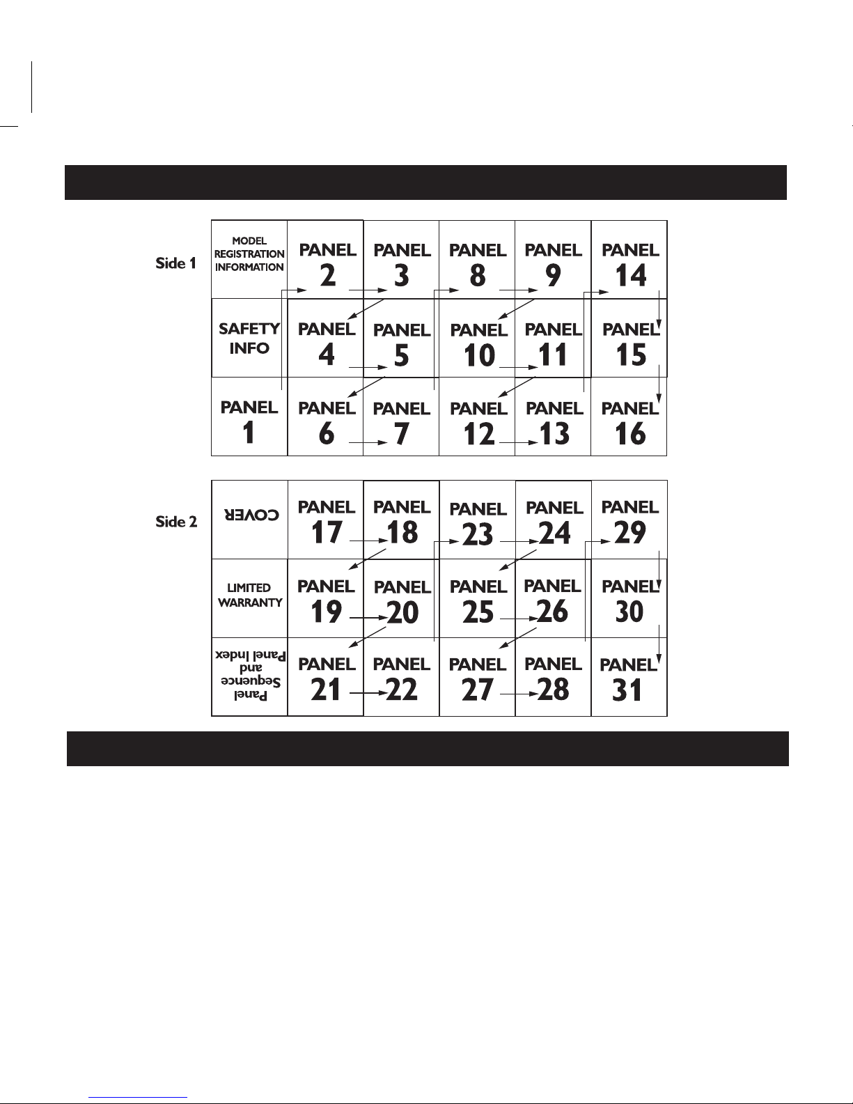
PANEL LAYOUT
USER MANUAL
Color Television
27MT3305/17
CAUTION
RISK OF ELECTRIC SHOCK
DO NOT OPEN
CAUTION: TO REDUCE THE RISK OF ELECTRIC SHOCK, DO NOT
REMOVE COVER (OR BACK). NO USER-SERVICEABLE PARTS
INSIDE. REFER SERVICING TO QUALIFIED SERVICE PERSONNEL.
ANTENNA LEAD IN WIRE
ANTENNA DISCHARGE UNIT
(NEC SECTION 810-20)
GROUND CLAMP
ANTENNA LEAD IN WIRE
ANTENNA DISCHARGE UNIT
(NEC SECTION 810-20)
GROUND CLAMP
Model No.:
L03 Magnavox English.qxd 5/20/05 10:15 AM Page 1
Page 3
Once your MAGNAVOX purchase is registered, you’re eligible to receive all the privileges of owning a
MAGNAVOX product. So complete and return the Warranty Registration Card enclosed with your purchase at once. And take advantage of these important benefits.
Return your Warranty Registration card today to
ensure you receive all the
benefits
you’re entitled to.
Warranty
Verification
Registering your product
within 10 days confirms your
right to maximum protection
under the terms and conditions of your MAGNAVOX
warranty.
Owner
Confirmation
Your completed Warranty
Registration Card serves as
verification of ownership in
the event of product theft or
loss.
Model
Registration
Returning your Warranty
Registration Card right away
guarantees you’ll receive all
the information and special
offers which you qualify for
as the owner of your model.
For Customer Use
Enter below the Serial No. which is located
on the rear of the cabinet. Retain this infor-
Know these
safetysymbols
This “bolt of lightning” indicates unin-
sulated material within your unit may
cause an electrical shock. For the safety of
everyone in your household, please do not
remove product covering.
The “exclamation point” calls atten-
tion to features for which you should
read the enclosed literature closely to prevent operating and maintenance problems.
WARNING: To reduce the risk of fire or
electric shock, this apparatus should not be
exposed to rain or moisture and objects
filled with liquids, such as vases, should not
be placed on this apparatus.
CAUTION: To prevent electric shock,
match wide blade of plug to wide slot, fully
insert.
ATTENTION: Pour éviter les choc électriques, introduire la lame la plus large de la
fiche dans la borne correspondante de la
prise et pousser jusqu’au fond.
CAUTION
RISK OF ELECTRIC SHOCK
DO NOT OPEN
CAUTION: TO REDUCE THE RISK OF ELECTRIC SHOCK, DO NOT
REMOVE COVER (OR BACK). NO USER-SERVICEABLE PARTS
INSIDE. REFER SERVICING TO QUALIFIED SERVICE PERSONNEL.
t
s
Congratulations on your
purchase, and welcome to the “family!”
Dear MAGNAVOX product owner:
Thank you for your confidence in MAGNAVOX.You’ve selected one of the bestbuilt, best-backed products available today.
We’ll do everything in our power to keep
you happy with your purchase for many
years to come.
As a member of the MAGNAVOX “family,”
you’re entitled to protection by one of the
most comprehensive warranties and outstanding service networks in the industry.
What’s more, your purchase guarantees
you’ll receive all the information and special
offers for which you qualify, plus easy
access to accessories from our convenient
home shopping network.
Most importantly, you can count on our
uncompromising commitment to your total
satisfaction.
All of this is our way of saying welcomeand thanks for investing in a MAGNAVOX
product.
P.S. Remember, to get the most
from your MAGNAVOX product, you must return your
Warranty Registration Card
within 10 days. So please mail
ANTENNA LEAD IN WIRE
ANTENNA DISCHARGE UNIT
(NEC SECTION 810-20)
GROUND CLAMP
ANTENNA LEAD IN WIRE
ANTENNA DISCHARGE UNIT
(NEC SECTION 810-20)
GROUND CLAMP
Page 4

ANTENNA LEAD IN WIRE
ANTENNA DISCHARGE UNIT
(NEC SECTION 810-20)
GROUND CLAMP
IMPORTANT SAFETY INSTRUCTIONS
Read before operating equipment
1. Read these instructions.
2. Keep these instructions.
3. Heed all warnings.
4. Follow all instructions.
5. Do not use this apparatus near water.
6. Clean only with a dry cloth.
7. Do not block any of the ventilation openings. Install in accordance
with the manufacturers instructions.
8. Do not install near any heat sources such as radiators, heat registers,
stoves, or other apparatus (including amplifiers) that produce heat.
9. Do not defeat the safety purpose of the polarized or grounding-type
plug. A polarized plug has two blades with one wider than the other.
A grounding type plug has two blades and third grounding prong.
The wide blade or third prong are provided for your safety.When
the provided plug does not fit into your outlet, consult an electrician
for replacement of the obsolete outlet.
10. Protect the power cord from being walked on or pinched particularly
at plugs, convenience receptacles, and the point where they exit from
the apparatus.
11. Only use attachments/accessories specified by the manufacturer.
12. Use only with a cart, stand, tripod, bracket, or table
specified by the manufacturer, or sold with the appara-
tus. When a cart is used, use caution when moving the
cart/apparatus combination to avoid injury from tip-over.
13. Unplug this apparatus during lightning storms or when unused for
long periods of time.
14. Refer all servicing to qualified service personnel. Servicing is required
when the apparatus has been damaged in any way, such as powersupply cord or plug is damaged, liquid has been spilled or objects
have fallen into apparatus, the apparatus has been exposed to rain
or moisture, does not operate normally, or has been dropped.
15. This product may contain lead and mercury. Disposal of these materi-
als may be regulated due to environmental considerations. For disposal or recycling information, please contact your local authorities or
the Electronic Industries Alliance: www.eiae.org
16. Damage Requiring Service - The appliance should be serv-
iced by qualified service personnel when:
A. The power supply cord or the plug has been damaged; or
B. Objects have fallen, or liquid has been spilled into the appli-
ance; or
C. The appliance has been exposed to rain; or
D. The appliance does not appear to operate normally or
exhibits a marked change in performance; or
E. The appliance has been dropped, or the enclosure damaged.
17. Tilt/Stability - All televisions must comply with recommended
international global safety standards for tilt and stability properties of
its cabinet design.
• Do not compromise these design standards by applying excessive
pull force to the front, or top, of the cabinet which could ultimately
overturn the product.
• Also, do not endanger yourself, or children, by placing electronic
equipment/toys on the top of the cabinet. Such items could unsuspectingly fall from the top of the set and cause product damage
and/or personal injury.
18. Wall or Ceiling Mounting - The appliance should be mount-
ed to a wall or ceiling only as recommended by the manufacturer.
19. Power Lines - An outdoor antenna should be located away from
power lines.
20. Outdoor Antenna Grounding - If an outside antenna is
connected to the receiver, be sure the antenna system is grounded so
as to provide some protection against voltage surges and built up
static charges.
Section 810 of the National Electric Code, ANSI/NFPA No. 70-1984,
provides information with respect to proper grounding of the mast
and supporting structure, grounding of the lead-in wire to an antenna discharge unit, size of grounding connectors, location of antennadischarge unit, connection to grounding electrodes, and requirements
for the grounding electrode. See Figure below.
21. Object and Liquid Entry - Care should be taken so that
objects do not fall and liquids are not spilled into the enclosure
through openings.comply with recommended international global safety
standards for tilt and stability properties of its cabinet design.
22. Battery Usage CAUTION - To prevent battery leakage that
may result in bodily injury, property damage, or damage to the unit:
• Install all batteries correctly, with + and - aligned as marked on
the unit.
• Do not mix batteries (old and new or carbon and alkaline, etc.).
• Remove batteries when the unit is not used for a long time.
ANTENNA LEAD IN WIRE
ANTENNA DISCHARGE UNIT
(NEC SECTION 810-20)
GROUND CLAMP
Note to the CATV system installer: This
reminder is provided to call the CATV system
Example of Antenna Grounding
as per NEC - National Electric Code
Page 5
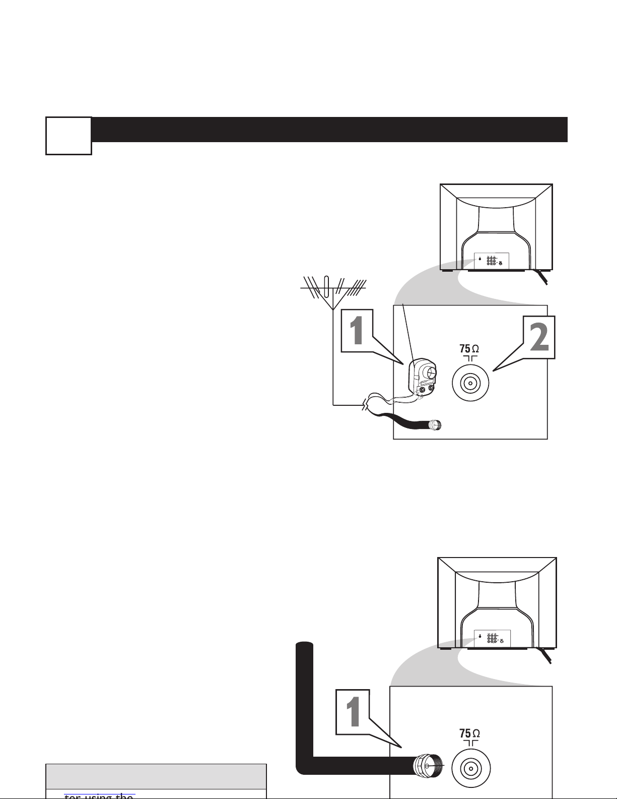
BASIC ANTENNA AND CABLE CONNECTIONS
Y
our home’s signal input might come from
a single (75 ohm) round cable, a
Converter Box, or from an antenna. In either
case the connection to the TV is very easy.
1
If your Cable TV signal or
Antenna signal is a round cable
(75 ohm) then you're ready to connect to the TV.
If your antenna has flat twinlead wire (300 ohm), you first need
to attach the antenna wires to the
screws on a 300 to 75 ohm adapter.
If you have a Cable Converter
Box: Connect the Cable TV signal
to the Cable Signal IN(put) plug on
the Converter.
2
Connect the Cable TV cable or
Antenna cable (or 300 to 75 ohm
adapter) to the 75Ω plug on the TV.
If you have a Cable Converter
Box: Connect the OUT(put) plug
from the Converter to the 75Ω plug
on the TV.
HELPFUL HINT
Back of TV
Cable signal
coming from
Cable Company
Antenna Connection
300 to 75Ω
Adapter
Combination
VHF/UHF Antenna
(Outdoor or Indoor)
Twin Lead
Wire
Round Cable
75Ω
Back of TV
Direct Cable Connection
75Ω Round
1
Page 6
C
ABLE
B
OX
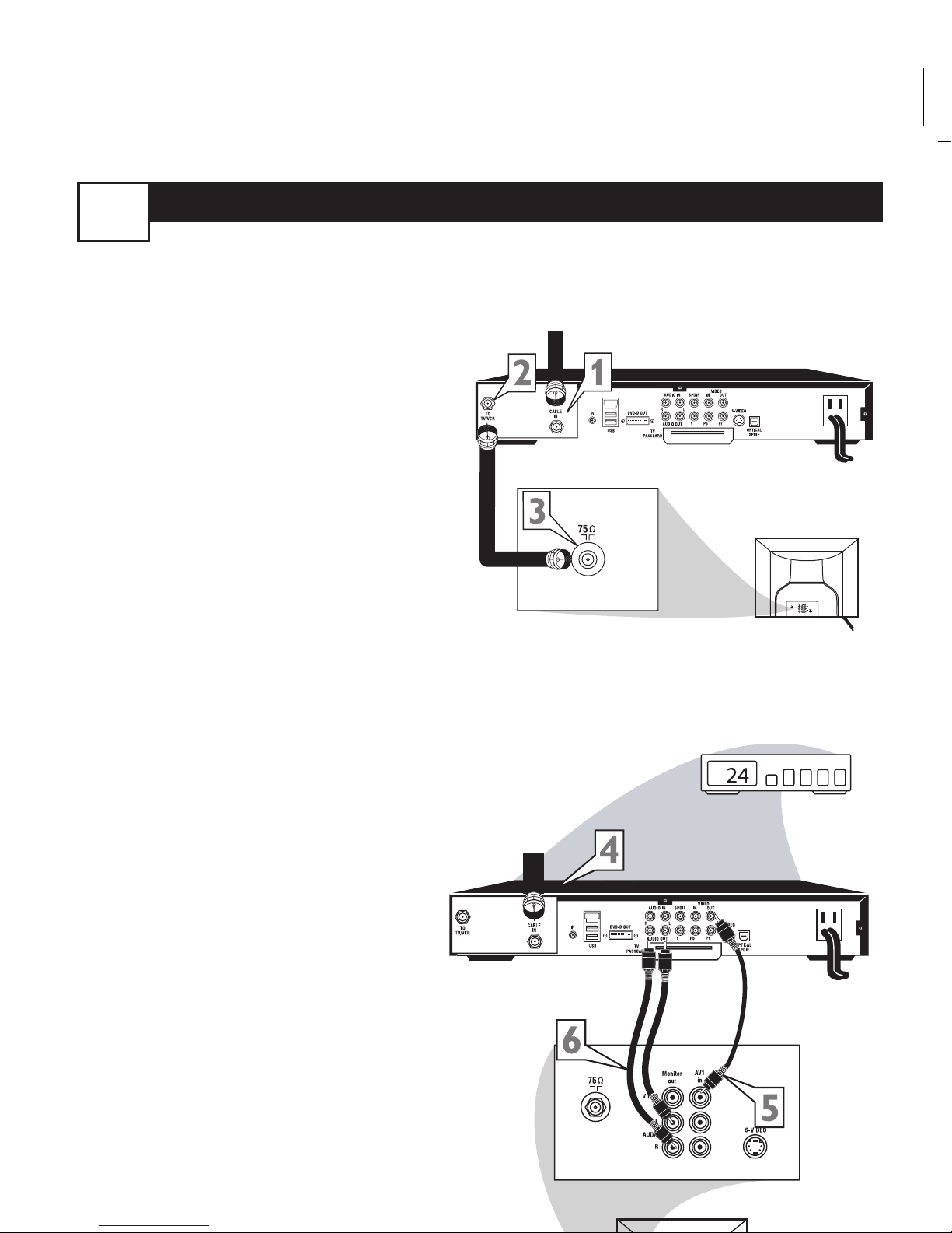
CONNECTIONS
2
I
f your cable signal uses a cable box or
decoder, follow the easy steps below to com-
plete the connection.
Cable Box (w/RF In/Outputs):
This connection will be mono.
1
Connect the Cable Company
supplied cable to
the signal IN(put)
plug on the back of the Cable Box.
2
Using a separate round coaxial cable,
connect one end to the
OUT(put)
(TO TV) plug on the back of the
Cable Box.
3
Connect the other end of the
round coaxial cable to the 75Ω
input on the back of the television.
Screw it down finger tight.
NOTE: If applicable, set the OUTPUT
CHANNEL SWITCH on the back of the
cable box to CH 3 or 4.Tune the TV to the
same channel and change channels at the
cable box. In some cases, the cable box will
automatically tune to either channel 3 or 4,
change channels until the picture appears.
Cable Box (w/Audio/Video Outputs):
This connection will supply Stereo sound.
4
Connect the Cable Company
supplied cable to
the cable signal
IN(put) plug on the back of the
Cable Box.
5
Using a RCA type Video Cable, connect one end of the cable to the
Video (or ANT, your cable box may be
labeled differently) Out jack on the
cable box and the other end to the
AV1 Video Input on the TV.
6
Connect one end of the Audio Left
and Right Cable to the left and
right Audio Out L & R jacks on
the cable box. Connect the other
end to the AV In Audio L & R Input
Jack Panel Back of Cable Box
Cable Signal IN from the
Cable Company
Round 75Ω
Coaxial Cable
Jack Panel Back of TV
Cable Signal IN
from the Cable
Company
Cable Box with A/V Outputs
Jack Panel Back of TV
Audio Cables
L (White) & R (Red)
Video Cable
(Yellow)
Cable Box (w/RF In/Outputs):
Cable Box (w/Audio/Video Outputs):
Page 7

Page 8

Page 9

Page 10

Page 11

Page 12

Page 13

Page 14

Page 15

Page 16

Page 17

Page 18

Page 19

THE 4:3 EXPAND FORMAT CONTROL
4:3
Expand 4:3
Format
4:3 Expand
Features
AutoLock
Format 4:3
123
POWER
CH
CH
VOL
VOL
STATUS
EXIT
SLEEP
MUTE
SMART
PICTURE SOUND
SURF
A/CH
45
6
789
0
CC
MENU
6
5
3
5
2
4
M
any times while watching movies from
a DVD player the image is shown in
“letter box” format.This is the format that
is shown in movie theaters. when shown on
a TV screen, the image will have areas of
black on top and bottom of the screen.
1
Press the MENU button on the
remote to display the on-screen
menu.
2
Press the CURSOR DOWN
¸¸
button until the word Features
is highlighted.
3
Press the CURSOR RIGHT
˙˙
button to display the Features
menu options (Autolock or
Format).
4
Press the CURSOR DOWN
¸¸
button until the word Format is
highlighted.
5
Press the
CURSOR RIGHT
˙˙
or LEFT
˝˝
buttons to select
one of the two options 4:3 or
Expand 4:3.
4:3 - Standard format for the TV.
Expand 4:3 - Enlarges the picture
to fill out the entire screen area,
eliminating the “letter box” effect.
6
When finished, press the STATUS /EXIT button to remove
the menu from the TV’s screen.
Note: The Expand 4:3 format can also
be activated using the CURSOR UP
˚˚
or DOWN
¸¸
buttons when the
onscreen menu is not being displayed.
Pressing these buttons will toggle the
standard 4:3 format and the Expand 4:3
15
T
broadcasters, or other program providers, that
contain program content advisories.When pro-
grammed by the viewer, a TV with Autolock™
can respond to the content advisories and block
program content that may be found objection-
able (such as offensive language, violence, sexual
situations, etc.).This is a great feature to censor
the type of viewing children may watch.
Autolock™ offers various BLOCKING
controls from which to choose:
Access Code - An Access Code must be
set to prevent children from unblocking
questionable or censored programming set
by their parents.
Channel Block - After an access code has
been programmed, you can block individual
channels including the A/V inputs.
Clear All - Allows you clear all channels
being blocked from your viewing set with
the Channel Block Control.
Block All - Allows you to block ALL chan-
nels and A/V inputs at one time.
Movie Ratings - Certain blocking options
exist which will block programming based on
ratings patterned by the Motion Pictures
Association of America.
TV Ratings - Just like the Movie Ratings,
programs can be blocked from viewing using
standard TV ratings set by TV broadcasters.
MO
G: General Audience - All ages admitted.
Most parents would find this program suit-
able for all ages.
PG: Parental Guidance Suggested -
programming contains material that parents
may find unsuitable for younger children.
PG-13: Parents Strongly Cautioned - This
16
L03 Magnavox English.qxd 4/15/05 5:33 PM Page 2
Page 20

U
NDERSTANDING
AUTOLOCK CONTROLS
T
he Autolock™ feature is an integrated cir-
cuit that receives and processes data sent by
broadcasters, or other program providers, that
contain program content advisories.When programmed by the viewer, a TV with Autolock™
can respond to the content advisories and block
program content that may be found objectionable (such as offensive language, violence, sexual
situations, etc.).This is a great feature to censor
the type of viewing children may watch.
Autolock™ offers various BLOCKING
controls from which to choose:
Access Code - An Access Code must be
set to prevent children from unblocking
questionable or censored programming set
by their parents.
Channel Block - After an access code has
been programmed, you can block individual
channels including the A/V inputs.
Clear All - Allows you clear all channels
being blocked from your viewing set with
the Channel Block Control.
Block All - Allows you to block ALL channels and A/V inputs at one time.
Movie Ratings - Certain blocking options
exist which will block programming based on
ratings patterned by the Motion Pictures
Association of America.
TV Ratings - Just like the Movie Ratings,
programs can be blocked from viewing using
standard TV ratings set by TV broadcasters.
MO
VIE
RATINGS
G: General Audience - All ages admitted.
Most parents would find this program suitable for all ages.
PG: Parental Guidance Suggested -
This
programming contains material that parents
may find unsuitable for younger children.
PG-13: Parents Strongly Cautioned - This
MOVIE RATINGS Continued
R: Restricted - This is programming is specifi-
cally designed for adults. Anyone under the age
of 17 should only view this programming with
an accompanying parent or adult guardian.
NC-17: No one under the age of 17 will
be admitted. - This type of programming
should be viewed by adults only.
X:Adults Only - This type of programming
contains one or more of the following: very
graphic violence, very graphic and explicit or
indecent sexual acts, very coarse and intensely
suggestive language.
TV
RA
TINGS
TV-Y -- Designed for a very young audience,
including children ages 2-6.
TV-Y7 -- It may be appropriate for children
age 7 and above who have acquired the development skills needed to distinguish between
make-believe and reality.
TV-G -- Suitable for most audiences, this type
of programming contains little or no violence,
no strong language, and little or no sexual dialogue or situations.
TV-PG -- This program contains material that
parents may find unsuitable for younger children. Could contain Moderate violence (V),
some sexual situations (S), infrequent coarse
language (L), or some suggestive dialogue (D).
TV-14 -- This program contains some material
that many parents would find unsuitable for
children under 14 years of age.This type of
programming contains one or more of the following: intense violence (V), intense sexual situations (S), strong coarse language (L), or
intensely suggestive dialogue (D).
TV-MA -- This program is specifically designed
to be viewed by adults and therefore may be
unsuitable for children under 17.This type of
programming contains one or more of the fol-
16
Page 21

SETTING UPANACCESS CODE
O
ver the next few panels you’ll learn how
to block channels and get a better
understanding of the rating terms for certain
programming.
First, let’s start by learning how to set a personal access code:
1
Press the MENU button on the
remote to display the on-screen
menu.
2
Press the CURSOR UP ˚˚or
DOWN
¸¸
buttons until the word
FEATURES is highlighted.
3
Press the CURSOR RIGHT
˙˙
button to display the FEATURES
menu options.
4
Press the
CURSOR UP ˚˚or
DOWN
¸¸
buttons
until the
words AUTOLOCK™ are highlighted.
5
Press the CURSOR RIGHT
˙˙
button. The screen will read,
“ACCESS CODE - - - - .”
6
Using the NUMBERED buttons,
enter 0, 7, 1, 1. “XXXX” appears
on the Access Code screen as you
press the numbered buttons.
“INCORRECT CODE” will
appear on the screen, and you will
need to enter 0, 7, 1, 1 again.
7
The screen will ask you to enter a
“New Code.” Enter a “new” 4
digit code using the NUMBERED buttons. The screen will
then ask you to CONFIRM the code
you just entered. Enter your new
code again.“XXXX” will appear
when you enter your new code and
17
Page 22

B
LOCK
C
HANNELS
A
fter your personal access code has been
set (see previous page), you are now
ready to select the channels or the A/V
Inputs you want to block out or censor.
Once you’ve entered your access code and
the Autolock™ features are displayed on
the screen:
1
Press the CURSOR UP
˚˚
or
DOWN
¸¸
buttons until the
words BLOCK CHANNELS are
highlighted.
2
Press the CURSOR RIGHT
˙˙
button to turn blocking ON or
OFF for that channel.When ON is
selected the channel will be
blocked.
3
Press the CH + or CH – button
to select other channels you wish
to block. Repeat step 9 to block the
new channel.
4
When finished, press the
STATUS/EXIT button to
remove the menu from the screen.
NOTE: If you ever forget your code, the
0, 7, 1, 1 code is the factory default and
can be used to enter and create a new
access code.
Enter your
Access Code to
view a tuned
channel that is
blocked with
Block Channel.
18
Page 23

BLOCK
/
CLEAR ALL CHANNELS AT THE SAME TIME
A
fter blocking specific channels there
may come a time when you want to
block or clear all the channels at the same
time.
Once you’ve entered your access code and
the Autolock™ features are displayed on
the screen:
1
Press the CURSOR UP
˚˚
or
DOWN
¸¸
buttons to select
either CLEAR ALL or BLOCK ALL.
2
If CLEAR ALL is selected, press
the CURSOR RIGHT
˙˙
but-
ton to clear all blocked channels.
All channels will be viewable.
If BLOCK ALL is selected,
press the CURSOR RIGHT
˙˙
button to turn the control ON or
OFF.When ON is selected, ALL
available channels will be blocked
from viewing.
3
When finished, press the
STATUS/EXIT button to
remove the menu from the screen.
NOTE: If you ever forget your code,
the 0, 7, 1, 1 code is the factory default
and can be used to enter and create a
new access code.
19
Page 24

MOVIE RATINGS
T
he Autolock™ feature can block pro-
gramming based on the Movie Industry
ratings.
Once you’ve entered your access code and
the Autolock™ features are displayed on
the screen:
1
Press the CURSOR UP
˚˚
or
DOWN
¸¸
buttons to highlight
the words MOVIE RATING.
2
Press the
CURSOR RIGHT
˙˙
button
to display the MOVIE
RATING options (G, PG, PG-13, R,
NC17, or X).
3
Press the CURSOR UP 3 or
DOWN 4 buttons to highlight
any of the Movie Rating options.
When highlighted, all these options
can be turned ON (which will allow
blocking) or OFF (which will allow
viewing).
4
Use the
CURSOR RIGHT
˙˙
button
on the remote to turn the
rating option ON or OFF.
When a rating level is chosen to be
blocked, any higher level rating will also
be blocked from viewing. (i.e.: If “R” is
selected to be blocked, NC-17 and X
will automatically be blocked.)
NOTE: If you ever forget your code, the
0, 7, 1, 1 code is the factory default and
can be used to enter and create a new
access code.
20
Page 25

Page 26

Page 27

Page 28

Page 29

Page 30

Page 31

Page 32

Page 33

Page 34

Page 35

Page 36

 Loading...