

Page 1
3121 233 45891
Important Notice/Warning . . . . . . . . . . . . . . . . . . . . .1
Basic TV Operation . . . . . . . . . . . . . . . . . . . . . . . . . .1
Remote Battery Installation . . . . . . . . . . . . . . . . . . .1
Remote Control Button Descriptions . . . . . . . . . . . .1
Hooking up the Television
Basic Cable/Cable Box TV Connections . . . . . . . . .2
Basic Antenna TV Connections . . . . . . . . . . . . . . . .2
AV1 Input Connections . . . . . . . . . . . . . . . . . . . . . .3
AV2 Input Connections . . . . . . . . . . . . . . . . . . . . . .3
S-Video Input Connection . . . . . . . . . . . . . . . . . . . .3
Component Video Input Connections . . . . . . . . . . .3
AV4 Input Connection . . . . . . . . . . . . . . . . . . . . . . .4
Monitor Output Connections . . . . . . . . . . . . . . . . . .4
Side (AV3) Audio/Video Input Connection . . . . . . .4
CONTENTS
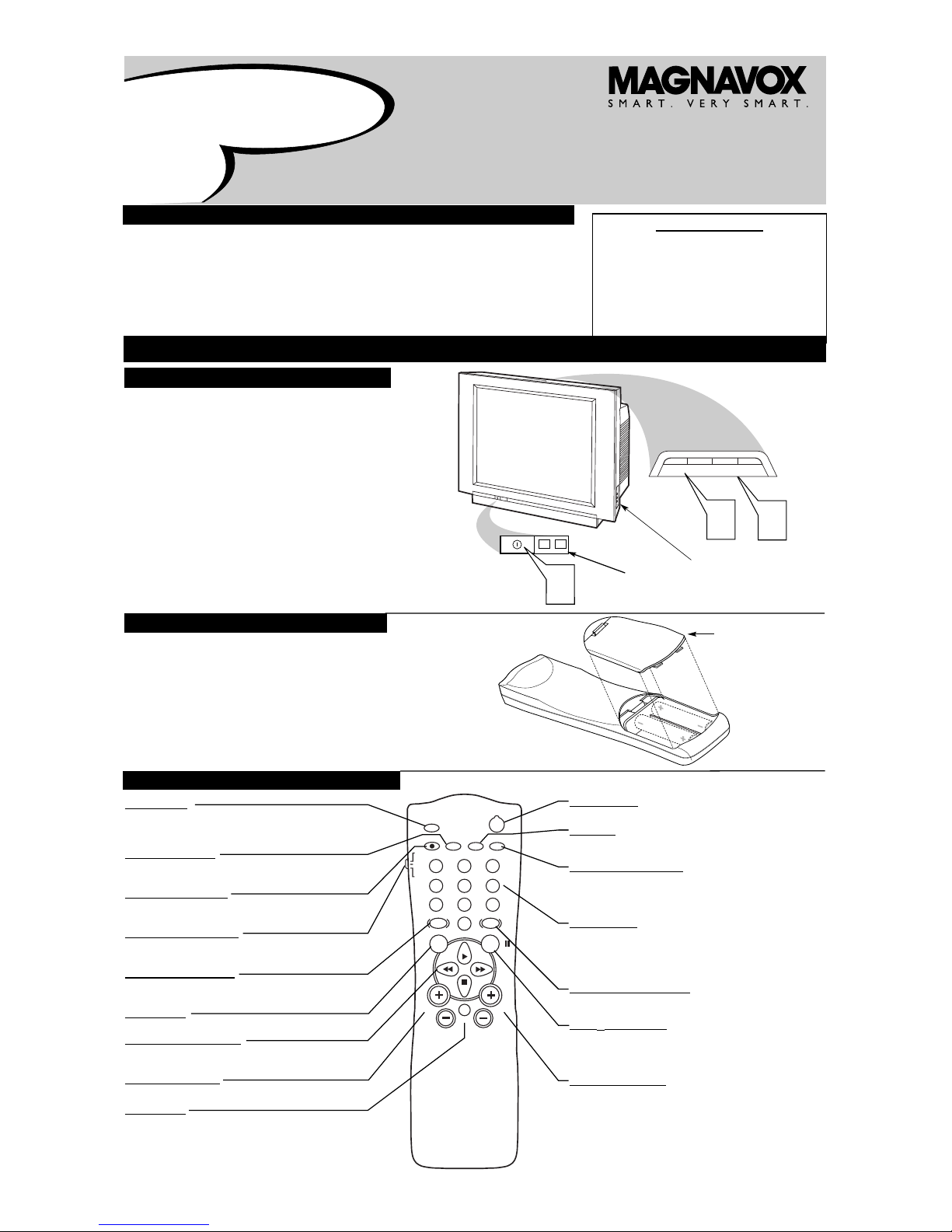
BASIC TV AND REMOTE OPERATION
Y
our television has a set of controls located on the top and front
of the cabinet for use when the remote control is not needed.
1
Press the POWER button on the front of the TV cabinet to turn
the TV ON.
Note: With AutoChron ON, the TV will search for a PBS channel to set the clock before powering itself on. This can take several seconds.
2
Press the VOLUME + button to increase the sound level or the
VOLUME - button to lower the sound level.
Pressing both buttons at the same time will display the
onscreen menu. After you are in the menu, use the Volume + or buttons to make adjustments or selections.
3
Press the CHANNEL + (Up) or - (DOWN) button to select
TV channels. Use these buttons to make adjustments or selections in the onscreen menu.
There is also a set of Audio and Video Input jacks located on the side of
the television cabinet. Refer to the Side AV3 Input section on page 4 of
this Quick Use and Hookup Guide.
T
ELEVISION
POWER
3
+
–
VOLUME
+
–
CHANNEL
2
1
Remote Sensor
Window
Audio, Video, S-Video
and Headphone Jacks
located on the side of
the television.
Volume and Channel buttons are located
on the top of the television cabinet.
T
o load the supplied batteries into the remote:
1
Remove the battery compartment door on the back of
the remote.
2
Place the batteries (2-AA) in the remote. Make sure the (+)
and (–) ends of the batteries line up correctly (the inside of
the case is marked).
3
Reattach the battery compartment door.
Be sure to point the remote at the Remote Sensor window on the
front of the television when using it to operate the television.
R
EMOTE
CONTROL
BATTERIES
REMOTE CONTROL BUTTONS
Quick Use and Setup Guide
Quick-Use and Setup Guide
IMPOR
TANT
NOTE: This owner's manual is used with several
different television models. Not all features (and
drawings) discussed in this manual will necessarily match those found with your television set.
This is normal and does not require you contacting your dealer or requesting service.
WARNING: TO PREVENT FIRE OR SHOCK
HAZARD DO NOT EXPOSE THIS UNIT TO
RAIN OR EXCESSIVE MOISTURE.
Color
Television
Color
Television
Battery
Compartment
Lid
POWER
SLEEP
A/CH STATUS/EXIT CC CLOCK
RECORD
TV
VCR
ACC
SMART
SMARTSMART
SOUND
PICTURE
MENU SURF
VOL
CH
MUTE
1
23
4
5
6
7
89
0
TV/VCR
POWER Button
Press to turn the TV or accessory devices on or off.
CC Button
Press to select Closed Captions. Refer to the Owner’s Manual for
details.
CLOCK • TV/VCR Button
In TV mode, press to see the Clock menu.
In VCR mode, press to put the VCR in TV or VCR position. Use VCR
position to watch tapes. Use TV position to view one TV channel while
recording another.
Number Buttons
Press to select TV channels. When selecting single-digit channels, press
the number of the desired channel. The TV will pause for a few seconds,
then tune to the selected channel. For quicker results, press "0," then the
number. For channels 100 and above, first press "1," then the next two
numbers of the channel.
SMARTPICTURE™ Button
Press to select a SmartPicture setting. These are preset picture controls
for different types of viewing sources and programs.
SURF/FF (pause) Button
In TV mode, press to select previous channels. You can place up to eight
channels in memory, then press SURF to quickly scan those channels. See
the owner's manual for details.
In VCR mode, press this button to pause a videotape.
CHANNEL +/– Buttons
Press to change channels.
SLEEP Button
Press to set the TV to turn itself off. It also can be used as an
Enter button when sending channel commands to Cable
Converter Boxes or VCRs.
STATUS/EXIT Button
Press to see the current channel number on the TV screen. Press to
clear the TV screen after control adjustments.
A/CH • RECORD Button
Press to toggle between the current channel and the previous channel. In VCR mode, press to start recording.
TV/VCR/ACC Mode Switch
Set to TV to control TV functions, VCR to control VCR functions, and
ACC for a Cable Converter, DBS, DVD Player, etc.
SMARTSOUND™ Button
Press to select a SmartSound control. These are preset sound
controls for different types of programming.
MENU Button
Press to access or remove the on-screen menu.
, , and ■ Buttons
Use these buttons to select and adjust menu items. Use with a
VCR for PLAY, FAST FORWARD, REWIND, and STOP.
VOLUME +/– Buttons
Press to adjust the TV sound level.
MUTE Button
Press to turn off the TV sound. Press again to return the sound to
its previous level.
Page 2
2
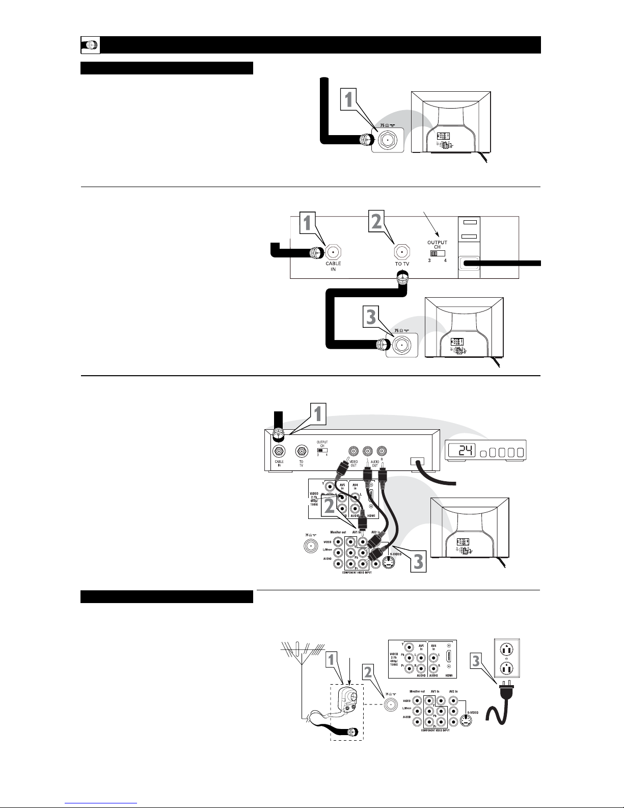
HOOKING UP THE TELEVISION
A
combination antenna receives normal broadcast channels (VHF 2–13 and UHF 14–69). Your connection is
easy because there is only one 75Ω (ohm) antenna plug on
the back of your TV, and that’s where the antenna goes.
1
If your antenna has a round cable (75 ohm) on the end,
then you're ready to connect it to the TV.
If your antenna has flat, twin-lead wire (300 ohm), you
first need to attach the antenna wires to the screws on a
300- to 75-ohm adapter.
2
Push the round end of the adapter (or antenna) onto the
75Ω (ohm) plug on the back of the TV. If the round end of
the antenna wire is threaded, screw it down finger tight.
3
Plug the television in to the wall outlet and turn the TV
on.
Refer to the TUNER and AUTOPROGRAM features
within the Directions for Use. TUNER should be set to the
ANTENNA option. AUTOPROGRAM can be set to program
all the available channels on your antenna signal into the television’s memory.
ANTENNA TV
Antenna Connection:
Jack Panel
Back of TV
Power Plug
from back of TV
AC Power
Wall Outlet
Round 75Ω
Coaxial Cable
from Antenna
Twin
Lead Wire
300 to 75-ohm
Adapter
Outdoor or Indoor Antenna
(Combination VHF/UHF)
The combination antenna receives normal
broadcast channels 2-13 (VHF) and 14-69 (UHF).
Y
our Cable TV input into your home may be a single (75 ohm)
cable or use a cable box decoder. In either case the connection is very simple. Follow the steps below to connect your cable
signal to your new television.
Direct Cable Connections:
This connection will supply Stereo sound to the TV.
1
Connect the open end of the round Cable Company supplied cable to the 75Ω input on the TV. Screw it down finger
tight.
Cable Box (w/RF In/Outputs):
This connection will NOT supply Stereo sound to the TV. The sound
from the cable box will be mono.
1
Connect the open end of the round Cable Company supplied cable to
the cable signal IN(put) plug on the back of
the Cable Box.
2
Using a separate round coaxial cable, connect one end to the
OUT(put) (TO TV) plug on the back of the Cable Box.
3
Connect the other end of the round coaxial cable to the
75Ω input on the back of the television. Screw it down finger
tight.
NOTE: Be sure to set the OUTPUT CHANNEL SWITCH on the
back of the cable box to CH 3 or 4, then tune the cable box on the
TV to the corresponding channel. Once tuned, change channels at
the cable box, not the television.
Cable Box (w/Audio/Video Outputs):
This connection will supply Stereo sound to the TV.
1
Connect the open end of the round Cable Company supplied cable to
the cable signal IN(put) plug on the back of
the Cable Box.
2
Using a RCA type Video Cable, connect one end of the
cable to the Video (or ANT, your cable box may be labeled
differently) Out jack on the cable box and the other end to the
AV1 Video Input on the TV.
3
Using a RCA type Audio Left and Right Cable, connect one
end to the left and right Audio Out L & R jacks on the
cable box. Connect the other end to the AV1 Audio L & R
Input jacks on the TV.
NOTE: Use the AV button on the TV remote control to tune to the
AV 1 channel for the cable box signal. Once tuned, change channels at
the cable box, not the television. Pressing the AV button repeatedly
will scroll all the AV Input channels, including the presently tuned
channel.
CABLE/CABLE BOX TV
Direct Cable Connection:
Cable Box with RF Inputs and Outputs Connection:
Cable signal
coming from
Cable Company
(Round 75Ω
coaxial cable)
Jack Panel Back of TV
Jack Panel Back
of Cable Box
Cable Signal
IN from the
Cable
Company
Round 75Ω
Coaxial Cable
Jack Panel Back of TV
Cable Box with Audio/Video Outputs Connection:
Cable Signal IN
from the Cable
Company
Jack Panel Back
of Cable Box with A/V Outputs
Jack Panel Back of TV
Audio Cables
L& R (Red, White)
Video Cable (Yellow)
Output Channel Switch
Page 3

HOOKING UP THE TELEVISION
3
POWER
SLEEP
A/CH STATUS/EXIT CC CLOCK
RECORD
TV
VCR
ACC
SMART
SMART
SMART
SMART
SMART
SMART
SOUND
PICTURE
MENU
MENU
SURF
SURF
VOL
VOL
CH
CH
MUTE
MUTE
1
2 3
456
7
8 9
0
TV/VCR
C
omponent Video inputs provide for the highest possible color
and picture resolution in the playback of digital signal source
material, such as with DVD players. The color difference signals
(Pb, Pr) and the luminance (Y) signal are connected and received
separately, which allows for improved color bandwidth information (not possible when using composite video or S-Video connections).
1
Connect the Component (Y, Pb, Pr) Video OUT jacks
from the DVD player (or similar device) to the (Y, Pb, Pr)
in(put) jacks on the TV. When using the Component Video
Inputs, it is best not to connect a signal to the AV1 in Video
Jack.
2
Connect the red and white AUDIO CABLES to the
Audio (left and right) output jacks on the rear of the accessory device to the Audio (L and R) AV1 in Input Jacks on
the TV.
3
Turn the TV and the DVD (or digital accessory device)
ON.
4
Press the CH+ or CH- buttons to scroll the available
channels until CVI appears in the upper left corner of the
TV screen.
5
Insert a DVD disc into the DVD player and press the
PLAY
button on the DVD Player.
C
OMPONENT VIDEO INPUTS
The description for the component video connectors may differ depending on the DVD player or accessory
digital source equipment used (for example, Y, Pb, Pr; Y, B-Y, R-Y; Y, Cr, Cb). Refer to your DVD or digital accessory owner’s manual for definitions and connection details.
H
ELPFUL HINT
T
he TV’s audio/video input jacks are for direct picture and
sound connections between the TV and a VCR (or similar
device) that has audio/video output jacks. Both the AV1 and AV2
Input Jack connections are shown to the right, but either one can be
connected alone. Follow the easy steps below to connect your accessory device to the AV1 and AV2 in Jacks located on the back of the
TV.
1
Connect the VIDEO (yellow) cable to the VIDEO AV1 in
(or AV2 in) jack on the back of the TV.
2
Connect the AUDIO (red and white) cables to the
AUDIO (left and right) AV1 in (or AV2 in) jacks on the
rear of the TV.
3
Connect the VIDEO (yellow) cable to the VIDEO OUT
jack on the back of the VCR (either one or two) or accessory device being used.
4
Connect the AUDIO (red and white) cables to the
AUDIO (left and right) OUT jacks on the rear of the VCR
(either one or two) or accessory device being used.
5
Turn the VCR (either one or two) or accessory device
and the TV ON.
6
Press the CH+ or CH- buttons on the remote to scroll the
channels until AV1 channel appears for accessory device
number one, or the AV2 channel appears for accessory
device number two. AV1 or AV2 will appear in the upper
left corner on the TV screen depending on the channel chosen.
7
With either of the VCRs (or accessory devices) ON and a
prerecorded tape (CD, DVD, etc.) inserted, press the
PLAY button to view the tape on the television.
AV1 & AV2 INPUTS
POWER
SLEEP
A/CH STATUS/EXIT CC CLOCK
RECORD
TV
VCR
ACC
SMART
SMARTSMART
SOUND
PICTURE
MENU SURF
VOL
CH
MUTE
1
23
456
7
89
0
TV/VCR
Note: The Audio/Video cables needed for this connection are not supplied with your TV. Please contact
your dealer orMagnavox at 800-705-2000 for information about purchasing the needed cables.
c
C
HECK IT OUT
AUDIO IN
(RED/WHITE)
VCR TWO (or accessory device)
(EQUIPPED WITH VIDEO AND
AUDIO OUTPUT JACKS)
VIDEO IN
(YELLOW)
BACK OF VCR 1
BACK
OF TV
AV1
Connection
AV2
Connection
VCR ONE (or accessory device)
(EQUIPPED WITH VIDEO AND
AUDIO OUTPUT JACKS)
AUDIO CABLES
(RED/WHITE)
COMPONENT
VIDEO CABLES
(Green, Blue, Red)
BACK OF TV
ACCESSORY DEVICE
EQUIPPED WITH COMPO-
NENT VIDEO OUTPUTS.
The CVI connection will be dominate over the AV1 in Video
Input. When a Component Video
Device is connected as described,
it is best not to have a video signal connected to the AV1 in
Video Input jack.
BACK OF VCR 2
AUDIO IN
(RED/WHITE)
VIDEO IN (YELLOW)
T
he S(uper)-Video connection on the rear of the TV can provide
you with better picture detail and clarity for the playback of
accessory sources than the normal antenna picture connections.
NOTE: The accessory device must have an S-VIDEO OUT(put)
jack in order for you to complete the connection on this page.
1
Connect one end of the S-VIDEO CABLE to the SVIDEO jack on the back of the TV. Then connect one end
the AUDIO (red and white) CABLES to the AV2 in
AUDIO L and R(left and right) jacks on the rear of the TV.
2
Connect other end of the S-VIDEO CABLE to the SVIDEO OUT jack on the back of the VCR. Then connect
the other ends of the AUDIO (red and white) CABLES to
the AUDIO (left and right) OUT jacks on the rear of the
VCR.
3
Turn the VCR and the TV ON.
4
Press the CH+ or CH- buttons on the remote to scroll the
channels until AV2 appears in the upper left corner of the
TV screen.
5
Slide the
TV/VCR/ACC Mode Switch
on the remote con-
trol to VCR to select the VCR accessory.
6
Now your ready to place a prerecorded video tape in the
VCR and press the PLAY button
.
S-VIDEO INPUTS
AV2
POWER
POWER
SLEEP
A/CH STATUS/EXIT CC CLOCK
RECORD
TV
VCR
ACC
SMART
SMARTSMART
SOUND
PICTURE
MENU
MENU
SURF
SURF
VOL
VOL
CH
CH
MUTE
MUTE
1
2 3
456
7
8 9
0
TV/VCR
The S-VIDEO and VIDEO
AV2 in(puts) are in parallel.
The S-VIDEO input is dominant when in use. If separate
video signals are connected to
the S-VIDEO and VIDEO
AV2 in(puts), the signal from
the VIDEO AV2 in(put) will
not be usable.
Note: The S-Video and Audio
cables needed for this connection are not supplied with your
TV. Please contact your dealer
or Magnavox at 800-705-2000
for information about purchasing the needed cables.
HELPFUL HINT
AUDIO CABLE
(RED/WHITE)
VCR
(EQUIPPED WITH
S-VIDEO JACKS)
S-VIDEO
CABLE
BACK OF VCR
Page 4

HOOKING UP THE TELEVISION
4
T
he Monitor (Audio/Video) out jacks are great for recording
with a VCR or used to connect an external audio system for
better sound reproduction.
For Audio System Connection:
1
Connect one end of the R(ight) and L(eft) AUDIO
(Monitor Out) jacks on the TV to the R and L audio input
jacks on your amplifier or sound system. Set the audio system’s volume to a normal listening level.
2
Turn the TV and audio system ON. You can now adjust
the sound level coming from the audio system with the
VOLUME (+) or (–) button on the TV or remote control.
For Second VCR Connection/Recorder:
NOTE: Refer to the previous page for the proper hookup of the
first VCR. Follow the instructions on how to tune to the AV 1
channel to view a pre-recorded tape.
The following steps allow you to connect a second VCR to
record the program while your watching it.
3
Connect one end of the yellow Video Cable to the
Monitor out VIDEO plug. Connect the other end to the
VIDEO IN plug on the second VCR.
4
Connect one end of the red and white Audio cable from
the Monitor out AUDIO L and R plugs on the TV to the
AUDIO IN plugs on the VCR.
5
Turn the Second VCR ON, insert a VHS tape and it’s
ready to record what’s being viewed on the TV screen.
M
ONITOR O
UTPUTS
A
U
X
/T
V
IN
P
U
T
P
H
O
N
O
IN
P
U
T
R
L
1
2
ANTENNA
OUT
ANTENNA
IN
VIDEO
AUDIO
IN
IN
OUTOUT
LR
ANTENNA
OUT
ANTENNA
IN
VIDEO
AUDIO
IN
IN
OUT OUT
RL
3
4
5
4
3
JACK PANEL
Located on the back of the TV
AUDIO CABLES
(Red & White)
AUDIO SYSTEM
with AUDIO INPUTS
AV OUT
AUDIO L(eft) and R(ight)
JACK PANEL
Located on the back of the TV
AUDIO CABLES
(Red & White)
FIRST VCR
(accessory device)
(Hookup from AV1 on previous page.)
Monitor OUT
VIDEO &AUDIO
L(eft) and R(ight)
SECOND VCR
VIDEO CABLE
(Yellow)
Audio System Connection
Second VCR Connection/Recorder
SIDE (AV3) AUDIO/VIDEO INPUTS
A
udio and Video Side Inputs are available for a quick connection of a VCR, to playback video from an accessory device.
1
Connect the video (yellow) cable from the Video output
on the accessory device to the Video (yellow) Input located
on the SIDE of the TV.
2
Connect the audio cable (red and white) from the Audio
Left and Right Outputs on the accessory device to the
Audio Left and right Inputs on the SIDE of the television.
3
Turn the TV and the accessory device ON.
4
Press the CH+ or CH- buttons on the remote to scroll the
channels until AV3 appears in the upper left corner of the
TV screen.
5
Press the PLAY button on the accessory device to
view playback, or to access the accessory device (camera,
gaming unit, etc.).
S-VIDEO
VIDEO
AUDIO
In
L
R
AV3
S-VIDEO
VIDEOAUDIO
LEFT RIGHT
1
2
3
3
5
POWER
POWER
SLEEP
SLEEP
A/CH
A/CHSTST
ATUS/EXIT
TUS/EXITCCCC
CLOCK
CLOCK
RECORD
RECORD
TV
TV
VCR
VCR
ACC
ACC
SMART
SMART
SMART
SMART
SMART
SMART
SOUND
SOUND
PICTURE
PICTURE
MENU
MENU
SURF
SURF
VOL
VOL
CH
CH
MUTE
MUTE
1
2 3
456
7
8 9
0
TV/VCR
TV/VCR
4
Jack Panel located
on the Side of TV
Jack Panel
of Accessory Device
Video Cable
(yellow)
Audio Cables
(red & white)
Optional
Headphones
When headphones re used the sound coming
from the TV speakers will be mute.
T
he AV4 Input Jacks provide HDMI Inputs at 1080i, for accessories
like HD Receivers. Connect an HD Reviver to the HDMI Input:
Please refer to your Receiver’s Owner’s Manual for more detailed hookup
options.
1
If using a Satellite Dish, Cable signal or Antenna signal, connect
the 75Ω round cable from a Satellite Dish to the SATELLITE IN
and/or the Cable and Antenna signals to the ANTENNA “A” or
“B” IN on the back of the HD Receiver.
2
Connect another 75Ω round cable from the OUT TO TV jack
on the HD Receiver to the 75Ω IN on the back of the TV.
3
Connect a HDMI cable from the HDMI OUT on the HD
Receiver to the AV4 HDMI Input jack on the back of the TV.
4
Connect the Audio L(eft) and R(ight) cables from the AUDIO
Outputs on the HD Receiver to the AV4 AUDIO Inputs on the
back of the TV.
5
With both the HD Receiver and the television ON,
Press the
CH+ or CH- buttons on the remote to scroll the channels
until AV4 appears in the upper left corner of the TV screen,
and you can
view the video input from the HDMI supplied sig-
nal.
T
he AV5 Input Jacks provide Component Video Inputs for accessories
like Digital Video Players.
Connecting a Digital device using the COMPONENT VIDEO Inputs:
1
Connect the Component (Y, Pb, Pr) Video OUT jacks from the
DVD player (or similar device) to the (Y, Pb, Pr) AV5 in(put)
jacks on the TV.
2
Connect the red and white AUDIO CABLES to the Audio (left
and right) output jacks on the rear of the accessory device to the
Audio (L and R) AV5 in(put) jacks on the TV.
3
Turn the TV and the DVD (or digital accessory device) ON.
4
Press the CH+ or CH- buttons on the remote to scroll the
channels until AV5 appears in the upper left corner of the
TV screen.
5
Press the PLAY button on the DVD (or digital accessory device)
to view the program on the television.
AV 4 INPUTS
S-VIDEO
OUT
OUT
OUT
L
R
AUDIO
VIDEO
COMP VIDEO
Y
Pb
Pr
AV5
2
1
3
5
POWER
POWER
SLEEP
A/CH STATUS/EXIT CC CLOCK
RECORD
TV
VCR
ACC
SMART
SMARTSMART
SOUND
PICTURE
MENU
MENU
SURF
SURF
VOL
VOL
CH
CH
MUTE
1
2 3
456
7
8 9
0
TV/VCR
4
POWER
POWER
SLEEP
SLEEP
A/CH
A/CHSTST
ATUS/EXIT
TUS/EXITCCCC
CLOCK
CLOCK
RECORD
RECORD
TV
TV
VCR
VCR
ACC
ACC
SMART
SMART
SMART
SMART
SMART
SMART
SOUND
SOUND
PICTURE
PICTURE
MENU
MENU
SURF
SURF
VOL
VOL
CH
CH
MUTE
MUTE
1
2 3
456
7
8 9
0
TV/VCR
TV/VCR
Coaxial Cable
Lead-in from Cable Outlet,
Converter Box,
or VHF/UHF Antenna
OUT TO TV
SATELLITE
IN
DIGITAL AUDIO
OUTPUT
VCR
CONTROL
S-VIDEO
PHONE JACK
VIDEOAUDIO
L
L
R
R
ACCESS CARD
ANTENNA BINANTENNA A
IN
Coaxial Cable
Lead-in from
Satellite Dish
Coaxial Cable Lead-in
from Alternate RF
Signal Source
2
1
11
4
3
5
AV5 Component Video Connection
AV4 HDMI Connection
Coaxial Cable
Lead-in from
Satellite Dish
Coaxial Cable Lead-in
from Alternate RF
Signal Source
Coaxial Cable Lead-in
from Cable Outlet,
Converter Box, or
VHF/UHF Antenna
AV 5 INPUTS
This TV’s side jack also has an S-Video input. This
can be used instead of the Video cable.
 Loading...