

Page 1
MDR 24MDR 24
MDR 24/96
MDR 24MDR 24
QUICK START GUIDE
24 TRACK/24 BIT, DIGITAL AUDIO HARD DISK RECORDER
Page 2
CAUTION AVIS
RISK OF ELECTRIC SHOCK
DO NOT OPEN
RISQUE DE CHOC ELECTRIQUE
NE PAS OUVRIR
CAUTION: TO REDUCE THE RISK OF ELECTRIC SHOCK
DO NOT REMOVE COVER (OR BACK)
NO USER-SERVICEABLE PARTS INSIDE
REFER SERVICING TO QUALIFIED PERSONNEL
ATTENTION: POUR EVITER LES RISQUES DE CHOC
ELECTRIQUE, NE PAS ENLEVER LE COUVERCLE. AUCUN
ENTRETIEN DE PIECES INTERIEURES PAR L’USAGER. CONFIER
L’ENTRETIEN AU PERSONNEL QUALIFIE.
AVIS: POUR EVITER LES RISQUES D’INCENDIE OU
D’ELECTROCUTION, N’EXPOSEZ PAS CET ARTICLE
MDR 24/96
A LA PLUIE OU A L’HUMIDITE
The lightning flash with arrowhead symbol within an equilateral
triangle is intended to alert the user to the presence of uninsulated
"dangerous voltage" within the product’s enclosure, that may be
of sufficient magnitude to constitute a risk of electric shock to persons.
Le symbole clair avec point de fl che l’int rieur d’un triangle
quilat ral est utilis pour alerter l’utilisateur de la pr sence
l’int rieur du coffret de "voltage dangereux" non isol d’ampleur
suffisante pour constituer un risque d’ l ctrocution.
The exclamation point within an equilateral triangle is intended to
alert the user of the presence of important operating and maintenance
(servicing) instructions in the literature accompanying the appliance.
Le point d’exclamation l’int rieur d’un triangle quilat ral est
employ pour alerter les utilisateurs de la pr sence d’instructions
importantes pour le fonctionnement et l’entretien (service) dans le
livret d’instruction accompagnant l’appareil.
Important Safety Instructions
1. Read instuctions — Read, understand and follow all safety and operating
instructions before using the MDR24/96.
2. Retain Instructions — Keep these safety and operating instructions for future
reference.
3. Heed Warnings — Follow all warnings on the MDR24/96 and in these
operating instructions.
4. Water and Moisture — Do not use the MDR24/96 near water – for
example, near a bathtub, kitchen sink, garden hose, incontinent poodle,
sweaty drummer, etc. – or when condensation has formed on the unit.
5. Heat and Ventilation — Locate the MDR24/96 away from heat sources such
as radiators, campfires, compost pits, heliarc welders, magma flows, etc. Do
not block MDR24/96 ventilation openings or install in spaces that prevent
adequate air circulation to the unit.
6. Power Sources — Connect the MDR24/96 only to a power source of the type
described in these operating instructions or as marked on the MDR24/96.
7. Power Cord Protection — Route power supply cords so that they are not likely
to be walked upon, tripped over, or abraded by items placed upon or against
them. Pay particular attention to cords at plugs, convenience receptacles, and
the point where they exit the MDR24/96.
8. Object and Liquid Entry — Do not drop objects or spill liquids into the
MDR24/96. Clean only with a damp cloth; do not clean with liquid or aerosol
cleaners.
9. Attachments — Use the MDR24/96 with only the accessories specified in
this manual.
10. Damage Requiring Service — The MDR24/96 should be serviced only by
qualified service personnel when:
A. The power supply cord or the plug has been damaged; or
B. Objects have fallen onto, or liquid has spilled into the unit; or
C. The unit has been exposed to rain or water; or
D. The unit does not appear to operate normally or exhibits a marked
change in performance; or
E. The unit has been dropped, or its chassis damaged.
11. Servicing — Do not attempt to service the MDR24/96. All servicing
should be referred to the Mackie Service Department.
12. Lightning — Unplug the MDR 24/96 during lightning storms or when
unused for long periods of time.
13. Grounding and Polarization — To prevent electric shock, do not use the
MDR24/96 polarized plug with an extension cord, receptacle or other
outlet unless the blades can be fully inserted to prevent blade exposure.
Do not defeat the MDR24/96 grounding by plugging into an ungrounded
receptacle or ground lift adapter.
This apparatus does not exceed the Class A/Class B (whichever is applicable)
limits for radio noise emissions from digital apparatus as set out in the radio
interference regulations of the Canadian Department of Communications.
ATTENTION — Le présent appareil numérique n’émet pas de bruits
radioélectriques dépassant las limites applicables aux appareils numériques de
class A/de class B (selon le cas) prescrites dans le réglement sur le brouillage
radioélectrique édicté par les ministere des communications du Canada.
FCC Information
NOTE: This equipment has been tested and found to comply
with the limits for a Class A digital devices, pursuant to Part 15
of the FCC Rules. These limits are designed to provide
reasonable protection against harmful interference when the
equipment is operated in a commercial installation. This
equipment generates, uses, and can radiate radio frequency
energy and, if not installed and used in accordance with the
instruction manual, may cause harmful interference to radio
communications. Operation of this equipment in a residential
area is likely to cause harmful interference in which case the
user will be required to correct the interference at his own
expense.
This product has been tested and complies with the
following standards and directives as set forth by the
European Union:
* EN 55022 Radiated and Conducted Emissions
* EN 61000-4-2 Electrostatic Discharge Immunity
* EN 61000-4-3 RF Electromagnetic Fields Immunity
* EN 61000-4-4 Electrical Fast Transient/Burst Immunity
* EN 60950/IEC 950 Electrical Safety Requirements
WARNING — To reduce the risk of fire or electric shock, do not expose this
appliance to rain or moisture.
WARNING — Before applying power to the MDR24/96, make sure that the
Voltage Selector switch next to the AC inlet jack on the rear panel is set to
the line voltage used in your region. Powering-on the MDR24/96 with
the Voltage Selector switch set incorrectly will cause an electrical and fire
hazard that may result in irreparable damage to the unit.
2
MDR 24/96
Page 3

Contents
Quick Start Guide
Introduction ----------------------------4
Save your Box! -------------------------------- 4
How To Use This Guide --------------------- 4
Conventions ---------------------------------- 5
About “Tape” --------------------------------- 5
Overview -------------------------------------- 6
Setup & Configuration ----------------7
Required Equipment ------------------------ 7
Installation------------------------------------ 7
I/O Cards & Cables ------------------------------- 8
Sync Card & Cables - Word Clock and Digital
Synchronization-------------------------------- 10
Mackie Media (Optional) ----------------------- 12
Remote 24 / Remote 48 (Optional) ---------- 13
Footswitch (Optional) --------------------------- 13
Power-Up-------------------------------------- 13
Configuration--------------------------------- 14
I/O Cards------------------------------------------- 14
Synchronization ---------------------------------- 16
Hookups ----------------------------------------18
Analog Hookup (AIO•8) ------------------------- 18
TDIF Hookup (DIO•8) ---------------------------- 20
ADAT Optical Hookup (DIO•8 or OPT•8) ---- 22
AES/EBU Hookup (PDI•8) ----------------------- 25
Appendix A: Compatible Cables ----39
Analog and Digital Multitrack Cables ----39
Other Cables---------------------------------- 40
Troubleshooting and service --------42
Notes-------------------------------------43
Please write your serial number here for future
reference:
Purchased at:
Date Of Purchase:
MDR24/96 Operation ----------------27
Opening Projects ---------------------------- 27
Time Display ---------------------------------- 28
Basic Transport Operations ----------------28
Locate Points and Looping----------------- 29
Track Editing ---------------------------------- 30
Cut / Join ------------------------------------------ 30
Copy ------------------------------------------------- 30
Paste / Insert-------------------------------------- 30
Undo / Redo -------------------------------------- 30
Creating Projects ---------------------------- 31
Monitoring ------------------------------------ 32
Metering and Setting Record Levels ----- 33
Recording ------------------------------------- 34
Footswitch Operation ---------------------- 35
Delete Last ------------------------------------ 36
Saving Projects --------------------------------36
Project Backup / Restore ------------------ 37
Purge Audio ------------------------------------38
Manual Part No. 0000107 Rev. A1 08/01
© 2001 Mackie Designs Inc., All rights reserved
Printed in the U.S.A.
Quick Start Guide
3
Page 4

MDR 24/96
Introduction
Save your Box!
Uncle Jeff’s Bottom Ten Reasons to Save the Box:
10. You think boxes grow on trees?
9. It’s actually a time capsule, packed with a biological code that can’t be
decrypted until 2043.
8. Its festive graphics will cheer up those other boxes forgotten in your
attic.
7. Impress your friends: tape it up and pretend that you actually have two
MDR24/96s.
6. If you throw it away, bad people will know you have a studio in your
house.
5. Someday, when paper costs more than steel, it could net you a fortune.
4. The MDR24/96 itself only costs $47.95. The balance is what you paid for
the box.
3. Properly sealed, it can be used as a flotation device in the unlikely event
of a water landing.
2. It’s a great place to hide your old digital 8-track recorder.
1. If you collect ten MDR24/96 boxes, Greg will come over for dinner (this
offer does not apply to dealers or distributors).
In the unlikely event that you should need to send the MDR24/96 back to Mackie
for service, please use the shipping box it came in. This box has been specially
designed to minimize damage to the MDR24/96 during shipping, so that it won’t
end up more broken than when you sent it.
How To Use This Guide
Welcome to the cutting edge of affordable multitrack recording and editing! We
know you’re feeling eager, but please take a few minutes and read this brief Quick
Start Guide before you jump into your first MDR24/96 session. The first part of
this guide explains how to install and configure the various MDR24/96 I/O cards
and connect the MDR24/96 to an analog or digital console. The second part
describes how to start a session, operate the basic transport and monitoring
controls, and explains the terms and conventions used to name, store, and retrieve
projects on disk.
We have purposely excluded all the extra stuff from this guide to give you just the
basic information you need to get going right away. For step-by-step tutorials, indepth feature descriptions, and endless technical details, see the MDR24/96
Technical Reference Manual on the companion CD-ROM. Updated manuals and the
latest software releases can be obtained via Mackie’s website at:
www.mackie.com.
4
MDR 24/96
Page 5

Conventions
The MDR24/96 Quick Start Guide uses the following conventions to help you find
information quickly:
Text Conventions
a) File or folder names (example: C:\HDR Projects\Ode To Masters\Ode
To Masters.hdr)
b) Software or hardware controls (example: Punch)
c) Proper names of objects in GUI or front/rear panel (example: Transport)
Icons
This icon identifies in-depth explanations of features and practical tips. Though
not required reading, they do offer some choice tidbits of knowledge that will
leave you wiser for the reading.
This icon identifies information that is critically important to the operation of the
MDR24/96. So for your own sake, please read these sections.
Quick Start Guide
About “Tape”
No, you’re not reading the wrong manual. Our goal was to build a hard disk
recorder that is comfortable for someone familiar with tape recording, but that
doesn’t require you to get a brain transplant from a computer geek to use. When
familiar terms such as Tape Inputs, Tape Returns, Transport, and the like are
applied to the MDR24/96, they mean exactly what you expect them to mean.
Where the well-worn shoe fits, we continue to wear it.
Quick Start Guide
5
Page 6
Overview
By combining traditional multitrack tape recording features with the power and
flexibility of hard disk recording, the Mackie Designs MDR24/96 takes multitrack
recording to a level never before achieved by a product in its price range. In
addition to the standard battery of traditional tape-based features, the MDR24/96:
• Combines the familiarity of a multitrack tape machine with the security of
non-destructive recording and non-degrading recording media.
MDR 24/96
• Records simultaneously on all 24 tracks at 44.1 or 48 kHz and on 12
tracks at 88.2 or 96 kHz. At 48 kHz the internal hard drive stores over
2200 track-minutes of 24-bit audio (90 minutes of 24 full tracks). That’s
more than six reels of 2” tape at 30 inches per second! At 96 kHz the drive
stores 1100 track-minutes of 24-bit audio (45 minutes of 24 full tracks).
• Has eight Virtual Takes per track, allowing you to record multiple passes
without having to change routing and bussing assignments or use
additional tracks.
• Iinterfaces with any analog or digital console. The MDR24/96 uses the
same I/O cards as the Mackie Digital 8•Bus console: the AIO•8 (24-bit
analog A/D and D/A), DIO•8 (TDIF/ADAT Optical), PDI•8 (AES/EBU),
and low-cost OPT•8 (ADAT Optical).
• Provides three convenient methods of backup: Mackie Media M•90, a
removable hard drive (also capable of 24-track recording and playback),
Mackie Media PROJECT, a removable drive using inexpensive, removable
2.2 GB ORB cartridges; and data transfer to another computer through the
MDR24/96’s 100 Base-T Ethernet port via the built-in FTP server.
• Offers two optional remote control devices – the compact Remote 24 for
smaller project studios, and the full-featured Remote 48 for controlling up
to 48 tracks on two MDR24/96 recorders.
Record Ready
24TRACK/24BIT DIGITAL AUDIO HARD DISK RECORDER
OL
OL
OL
OL
OL
2
2
2
4
4
4
7
7
7
10
10
10
15
15
15
20
20
20
25
25
25
30
30
30
35
35
35
40
40
40
50
50
50
REC REC REC REC REC REC REC REC REC REC REC
POWER
ON
OL
2
2
2
4
4
4
7
7
7
10
10
10
15
15
15
20
20
20
25
25
25
30
30
30
35
35
35
40
40
40
50
50
50
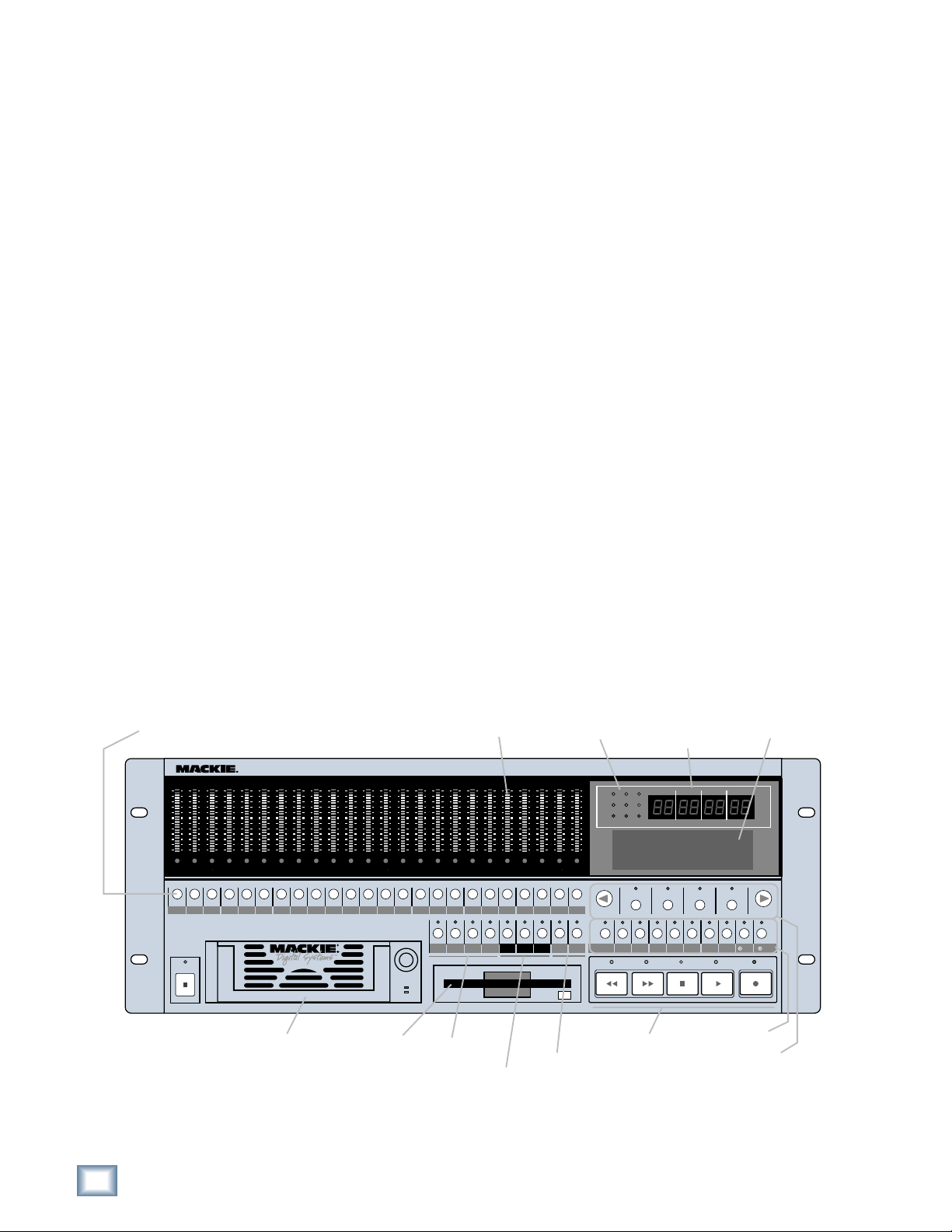
Media Tray Floppy Drive
Meter Display
OL
OL
OL
OL
OL
OL
OL
OL
OL
OL
OL
OL
OL
2
2
2
2
2
2
2
2
2
2
4
4
4
4
4
4
4
7
7
7
7
10
10
15
15
20
20
25
25
30
30
35
35
40
40
50
50
7
10
10
10
15
15
15
20
20
20
25
25
25
30
30
30
35
35
35
40
40
40
50
50
50
4
7
7
7
10
10
10
15
15
15
20
20
20
25
25
25
30
30
30
35
35
35
40
40
40
50
50
50
REC
REC REC REC REC REC REC REC REC REC REC REC REC
Locate &
Loop
2
4
4
4
7
7
7
10
10
10
15
15
15
20
20
20
25
25
25
30
30
30
35
35
35
40
40
40
50
50
50
LOC 2LOC 1 STORE
Monitoring &
Record Safe
OL
2
2
2
4
4
4
7
7
7
10
10
10
15
15
15
20
20
20
25
25
25
30
30
30
35
35
35
40
40
40
50
50
50
2019181716151413121110987654321
REC
LOOP
SAFE
1–2
OL
OL
2
2
4
4
7
7
10
10
15
15
20
20
25
25
30
30
35
35
40
40
50
50
21
ALL
AUTO
AUTO
INPUT
TAKE
INPUT
Auto Take &
Time code
Chase
Status Display
MDR 24/
OL
2
44.1k
4
7
VARI
10
15
ERROR
20
25
30
PROJECT: Little love
35
40
PLAYLIST: Playlist 1
50
DRIVE: C:Internal
AVAIL: 01:35:00
242322212019181716151413121110987654321
242322
T-CODE
DELETE LAST PROJECT BACKUP DISK UTIL SYSTEM DIGI-I/O SYNC DEC INC
CHASE
REWIND
Transport
TRACK/
16 BIT
EDIT
48k
TC CLOCK
Current
Time Display
96
96k
24 BIT
BARS
FAST FWD
System Control
HIGH RESOLUTION AUDIO
44.1/48/96K SAMPLE RATES
MINUTESHOURS
SECONDS FR AMES
SELECTSELECTSELECT
STOP
LCD Control
BEATS
SELECT
PLAY
LCD Display
TICKS
RECORD
6
MDR 24/96
Page 7
Setup & Configuration
This chapter explains how to set up and configure the MDR24/96 for use in your
studio. Two application examples show how to interface the MDR24/96 with
analog and digital recording consoles.
Required Equipment
Of course, there’s more to a studio than a recorder and some musicians. At a
minimum, you’ll need the following to make the MDR24/96 feel at home:
• 3 Mackie 8-channel I/O (input/output) cards.
• A console with a minimum of 24 tape sends (busses or direct outputs) and
returns (line inputs or monitor returns). If your analog console has only 8
tape sends, use Y-cord splitters to send tape out 1 to MDR24/96 Inputs 1,
9 and 17; tape out 2 to MDR24/96 Inputs 2, 10, and 18, and so forth.
• Cables to connect the MDR24/96 to the console: 3 or 6 multi-channel
snakes or fiber optic cables, depending on your I/O setup.
• All the stuff that typically connects to a console: microphones,
instruments, outboard equipment, control room monitors, and so on.
Quick Start Guide
Installation
This section describes how to install the I/O cards and how to connect the
MDR24/96 to your console. Before you begin, you should choose a location for
your MDR24/96 considering the following:
• If you’re not using the Remote 24, or Remote 48, position the front panel
within convenient reach of your normal recording/mixing position. Be
aware that although analog and AES/EBU cables can be fairly long, TDIF
Optical and Remote 24/Remote 48 cables are limited to about 10 meters.
ADAT Optical cables can reach up to about 15 meters.
• The MDR24/96 requires a reliable AC power source with a good ground.
Do not use a ground lift adapter or plug the MDR24/96 into an
ungrounded receptacle. Remember, this is a computer. Using an
uninterruptible power supply (UPS) to power the MDR24/96 is a good idea
to avoid an unexpected shutdown and protect it from transient line
voltages.
Warning!
Before applying power to the MDR24/96, make sure that the Voltage Selector
switch next to the AC inlet jack on the rear panel is set to the line voltage used
in your region. Powering-on the MDR24/96 with the Voltage Selector switch
set incorrectly will cause an electrical and fire hazard that may result in
irreparable damage to the unit.
Quick Start Guide
7
Page 8
MDR 24/96
OPT•8
ANALOG I/O
INPUT OUTPUT
AIO•8
APOGEE
DIGITAL I/O
ADAT OPTICAL
PDI•8
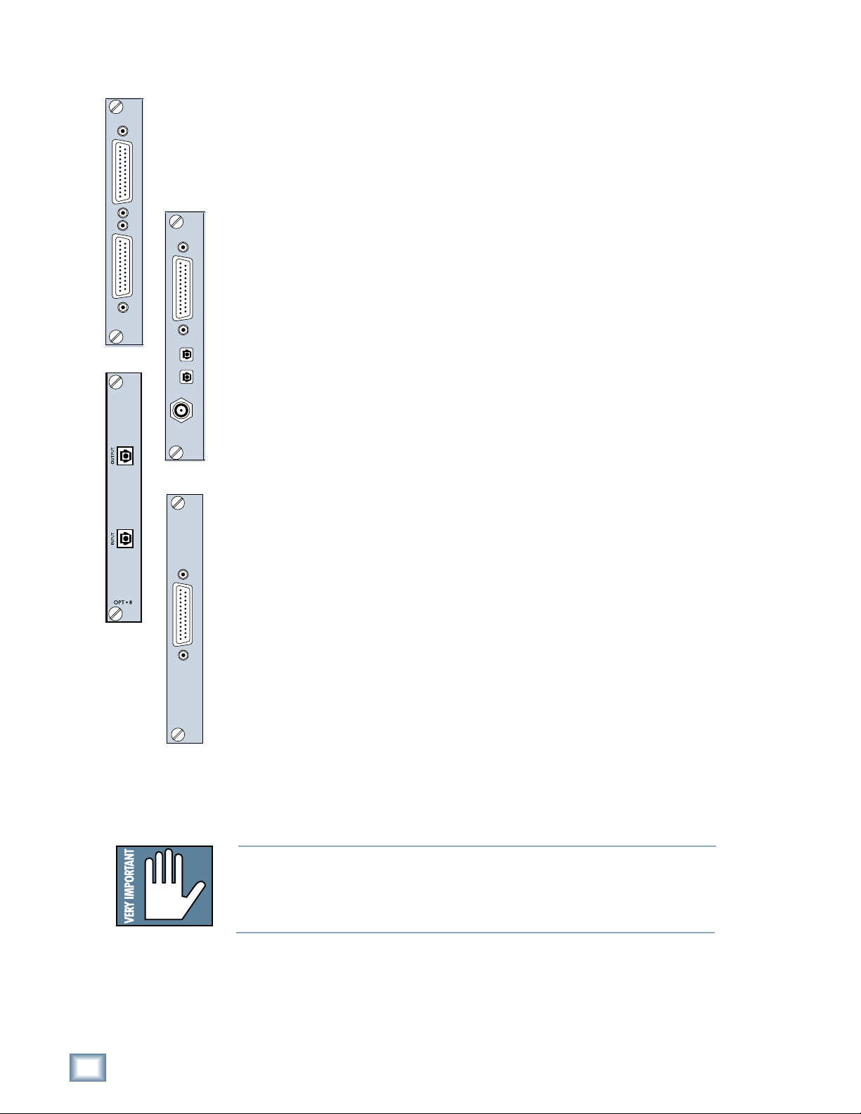
I/O Cards & Cables
While the MDR24/96 ships with AIO•8 cards already installed, three other flavors
of I/O cards are also available. All I/O cards can be mixed and matched in any
combination.
AIO•8
• Each AIO•8 provides 8 analog line-level inputs and outputs on two 25-pin
D-subminiature (DB25) connectors. These connectors are pin-for-pin
DIO•8
TDIF
IN OUT
SYNC
compatible with the analog (not TDIF) DB25 connectors found on the
TASCAM DTRS recorders. DB25 cables that break out to XLR or 1/4” TRS
connectors for mating with your console are readily available.
DIO•8
• Each DIO•8 provides 8 digital inputs and outputs in two formats:
1. TASCAM Digital Interface (TDIF) provides 8 input and output channels
of digital audio on a single DB25 connector. It requires a TASCAM
PW-88D or equivalent TDIF-compatible cable.
2. ADAT Optical provides 8 channels of digital audio on fiber-optic cable.
Two optical cables are required for each card, one for inputs, the other
for outputs. Both cables must connect to the same device, creating a
closed loop.
3. The DIO•8 also provides a TDIF word clock sync output for use with
older TASCAM equipment.
OPT• 8
• The OPT•8 is a low-cost, ADAT Optical-only version of the DIO•8 card.
The previous ADAT information also applies to this card.
PDI• 8
PDI• 8
AES/EBU I/O
• Each PDI•8 carries four stereo pairs (eight channels) of digital input and
output on a single DB25 connector. This card supports the AES/EBU
(IEC-958 Type 1) digital interfacing standard carrying two channels of
digital audio on a single balanced cable. The PDI•8 can also be configured
for the consumer (IEC-958 Type 2, or S/PDIF) data format if required.
DB25 cables that break out to XLR connectors, and double-ended DB25 to
DB25 AES/EBU cables for mating with your console, are readily available.
The PDI•8 is the only Mackie I/O card that currently supports 88.2 or 96
kHz operation. At these Sample Rates the PDI•8 card runs in “doublewide” (dual-wire) mode. In double-wide mode, the PDI•8 carries four mono
channels of digital I/O by transmitting two consecutive 88.2/96k samples
of the same channel on a single conductor.
Note: Different manufacturers use different wiring standards for DB25 interface cables (both analog and digital) that otherwise look the same. Make
sure the cable you are using is the correct one. See Appendix A for a list of
compatible MDR24/96 I/O card cables.
8
MDR 24/96
Page 9
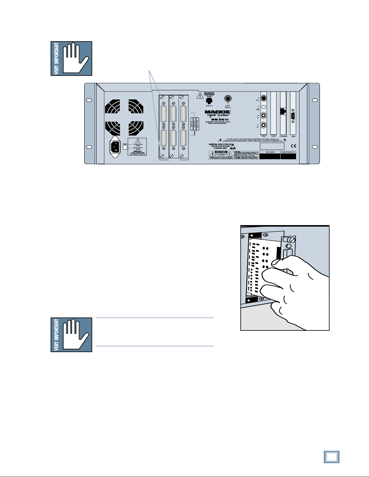
To replace the AIO-8 cards with different I/O cards:
1. If the MDR24/96 is plugged into AC power, unplug it.
2. Unscrew the thumbscrews at the top and bottom of each I/O card to be
removed. Grasp one thumbscrew with each hand and gently pull the card
out.
ANALOG I/O ANALOG I/O ANALOG I/O
M
INPUT OUTPUT
INPUT OUTPUT
INPUT OUTPUT
TAPE IN/OUTS
3. Before you take I/O cards from their bags, touch a grounded metal object
to discharge any static electricity from your body.
4. Remove the new I/O card from its anti-static bag and put the I/O
card you just removed from the MDR24/96 into the bag.
Quick Start Guide
5. Hold the new card so the component side
faces left and line up the top and bottom
edges with the white card guides. Push the
card all the way into the slot until its
faceplate is flush with the back panel.
6. Hand-tighten the thumbscrews at the top
and bottom of the card. Do not use a
screwdriver.
If you want to hook up the MDR24/96 I/O cables
to your console right now, see the console hookup
diagrams in Hookups. Be sure to come right back
here when you’re done.
Note:Note:
Note: Always hand tighten the thumbscrews
Note:Note:
at the top and bottom of all I/O cards before operating the MDR 24/96.
Quick Start Guide
9
Page 10
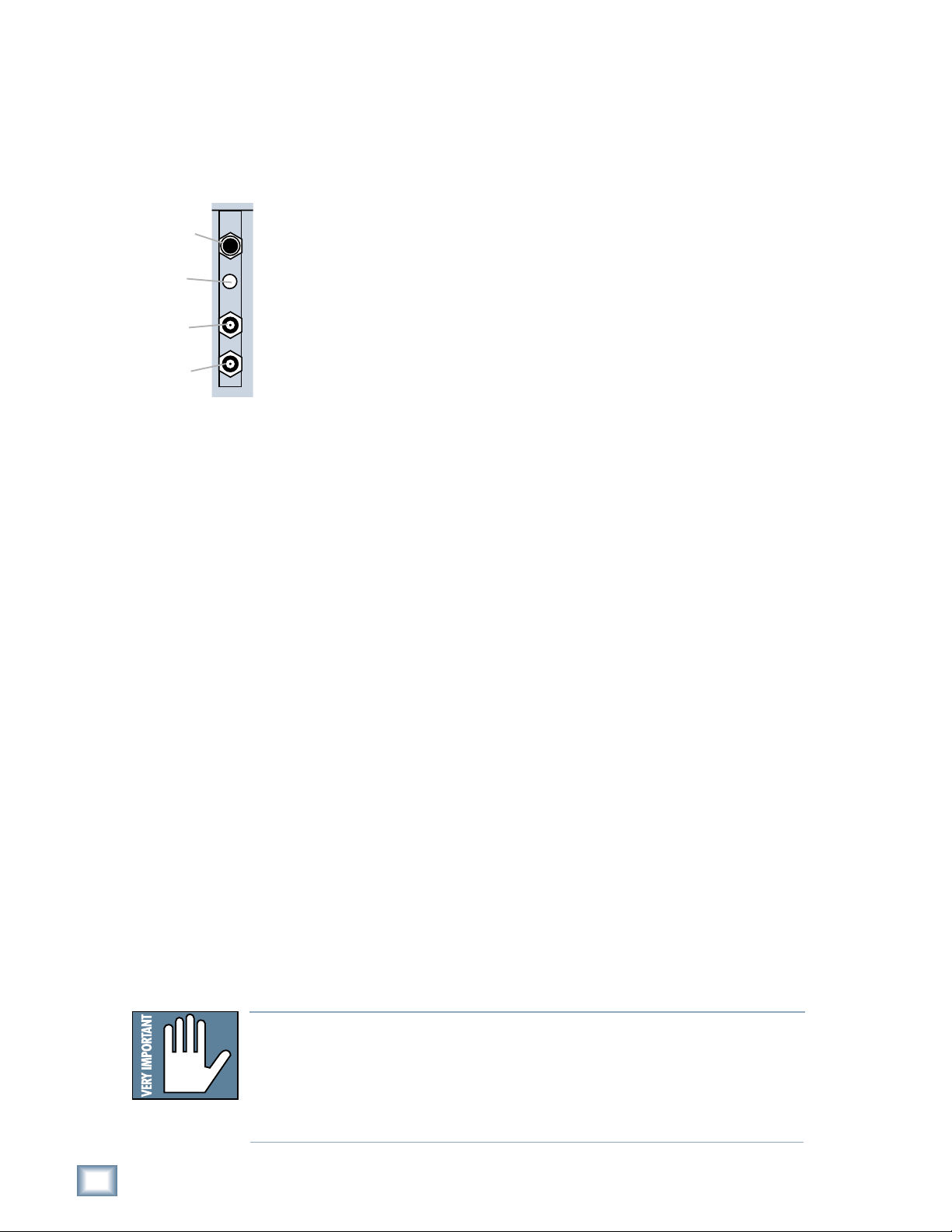
SMPTE Input/
Output
MDR 24/96
Termination
Switch
Word Clock/
Video Input
Word Clock
Output
Sync Card & Cables - Word Clock and Digital Synchronization
The Sync Card provides ports to synchronize the MDR24/96’s sample clock and
time/transport position to other equipment. The functions of the jacks and switch,
from top to bottom are:
• SMPTE Input / Output – This 1/4” TRS jack serves as an input when
slaved to incoming SMPTE time code, and as an output when generating
SMPTE time code to synchronize other devices with the MDR24/96.
• Termination Switch – This pushbutton switch selects the termination
impedance of the Word Clock / Video Input jack. When the switch is out,
the impedance is 3.3kΩ (bridging); when in, the impedance is 75Ω
(terminated).
• Word Clock / Video Input – This BNC jack receives either word clock,
composite video, or video blackburst as determined by the MDR24/96
SYNC
Whenever digital audio connections are made between devices, the sample clock
of every device must run at exactly the same rate. This is usually accomplished by
selecting one device as the “master” clock source and distributing its word clock
signal to all the “slave” devices in the system. The master is configured to run
from its internal clock, and the slaves from external word clock. Some digital
interfaces are self-clocking (such as the AES input on many DAT machines) and
do not require a separate work clock connection. Others simply cannot be
configured as slaves. The master/slave designation must be correctly made for
each device to avoid the clicks and pops associated with asynchronous clocks.
Sample Clock setting. Use this input when the MDR24/96 is operating as a
word clock slave.
• Word Clock Output - This BNC jack transmits word clock to other devices
in the system when the MDR24/96 is configured as the clock master.
Whenever time code (positional) synchronization is used, all the devices in a
system, both analog and digital, must be synchronized to a common timing (speed)
reference. This is often achieved by distributing video from a master video sync
generator (sometimes called “house sync”) to all the slave devices in the system
when word clock cannot otherwise be used. The MDR24/96, like many other
digital devices, can synchronize its sample clock to a video signal. However, video
does not provide enough timing precision to properly synchronize devices whose
digital audio paths are interconnected; word clock must be used instead.
Generally it doesn’t matter which device in a system serves as the word clock
master, except when synchronizing to time code or video. For example, if your
MDR24/96 Inputs and Outputs are connected to the Tape Inputs and Outputs of a
Mackie Digital 8•Bus console using TDIF, either the MDR24/96 or D8B can be the
word clock master. However, if you later synchronize the MDR24/96 to time code
from a VTR, you must lock the VTR and MDR24/96 to a master video sync source
and lock the D8B (which can’t sync to video) to word clock from the MDR24/96.
In this case the MDR24/96 becomes both a video slave and a word clock master.
For more detailed information on setups involving video and time code
synchronization, see the Technical Reference manual.
Note: Note:
Note: For audio-for-video applications, the MDR24/96 can lock its word clock to
Note: Note:
a video signal. In this configuration, there must be only one word clock dependent device (The MDR24/96) locked to the video source. The MDR24/96 then
becomes the word clock master for the other digital devices in the system (for
example, a digital mixing console). Do not attempt to lock multiple digital devices to the video signal, or you’ll get clicks.
10
MDR 24/96
Page 11
The following are recommended setups for establishing proper sample clock
synchronization with the devices connected to the MDR24/96 digital I/O cards.
TDIF (DIO•8)
With the MDR24/96 as a master, connect Word Clock Out of the MDR24/96
to Word Clock In on the receiving device(s). If connecting to older TASCAM
DTRS recorders, use the Sync Out port on the first DIO
Word Clock Out. If there is more than one DTRS recorder in the chain,
connect Sync Out to the word clock input of the first DTRS recorder only; the
other recorders are synchronized through their interconnecting DTRS cables.
With the MDR24/96 operating as a slave to another TDIF device, connect the
word clock output from the master TDIF device to Word Clock In on the
MDR24/96.
•8 card instead of
ADAT Optical (DIO•8, OPT•8)
With the MDR24/96 as a master, set the receiving device(s) to derive sample
clock from their ADAT Optical ports if the ports are self-clocking. In this
case, no word clock connection is necessary. If the ADAT Optical ports on the
receiving devices are not self-clocking, connect Word Clock Out of the
MDR24/96 to Word Clock In on the receiving device(s).
With the MDR24/96 configured as a slave, connect the word clock out of the
master ADAT Optical device to Word Clock In on the MDR24/96.
Quick Start Guide
AES/EBU (PDI•8)
With the MDR24/96 as a master, set the receiving device(s) to derive their
sample clock from the AES/EBU ports if the ports are self-clocking. In this
instance, no word clock connection is necessary. If the AES/EBU ports on the
receiving device(s) are not self-clocking, connect Word Clock Out of the
MDR24/96 to Word Clock In of the receiving device(s).
With the MDR24/96 as a slave, connect the word clock out of the master
AES/EBU device to Word Clock In on the MDR24/96.
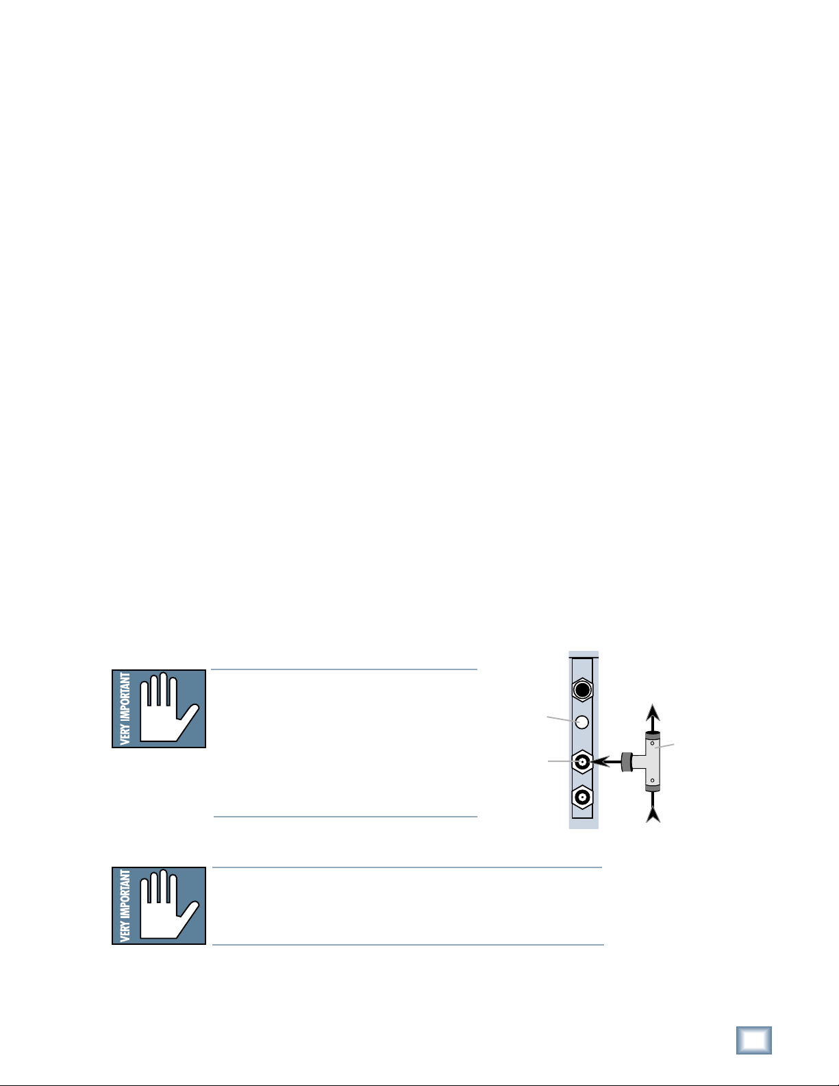
Note:Note:
Note: Use 75 Ω coaxial cables when con-
Note:Note:
necting word clock or video to the Sync
Card Word Clock/Video input jack. If the
Termination
Switch
Word Clock to
other Slaves
MDR24/96 is at the end of a cable that’s
connected to several devices, push the
Termination Switch in; otherwise leave it
Word clock
input jack
out and use a BNC Tee adapter to feed the
signal on to the next device in the chain.
Note:Note:
Note: If you are using an MDR24/96 with the Mackie Digital
Note:Note:
SYNC
Word Clock
From Master
8•Bus console, you may need to turn on the Digital 8•Bus first.
The Clock I/O on the D8B prefers not to see an active signal at
its Word Clock input when it powers up.
BNC-Tee
adaptor
Quick Start Guide
11
Page 12
MDR 24/96
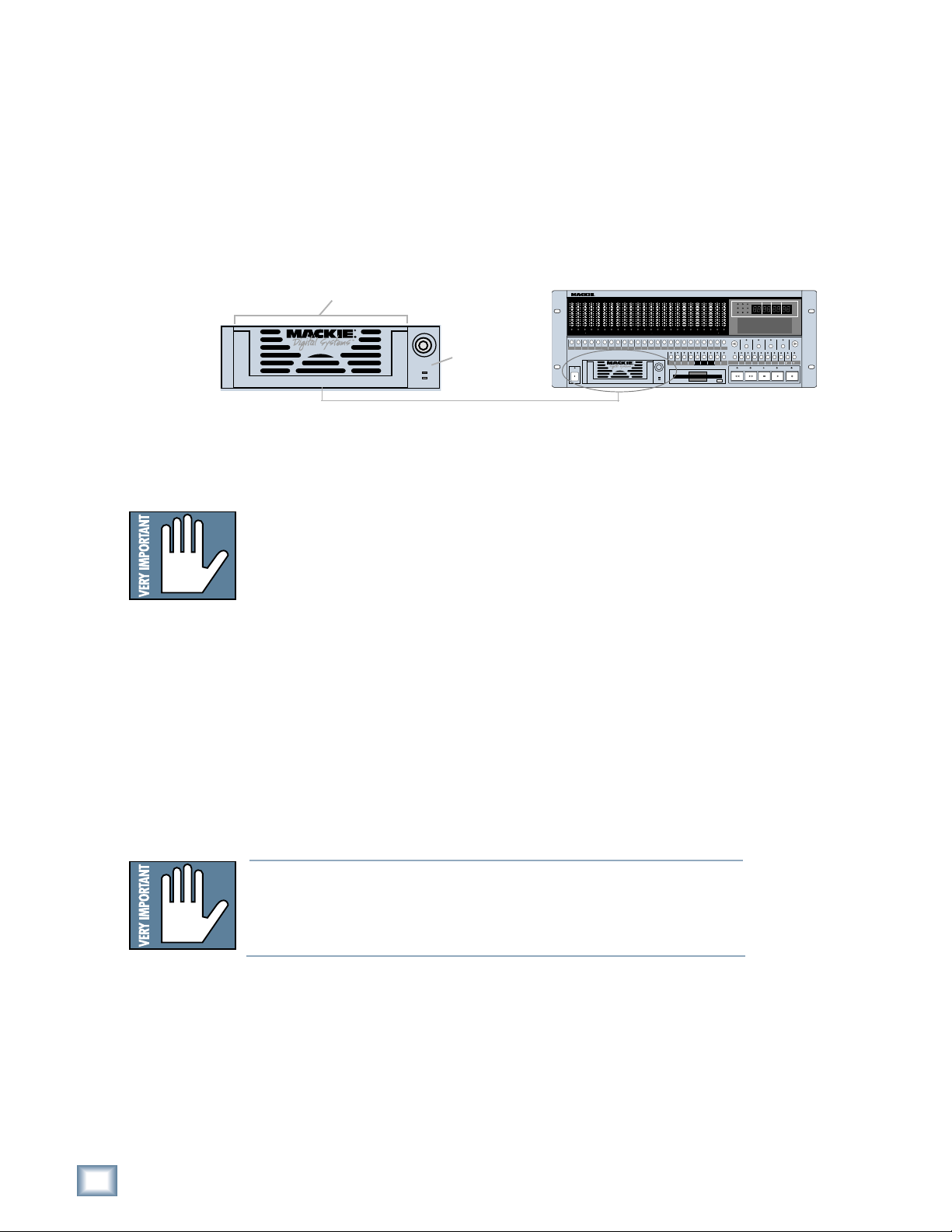
Mackie Media (Optional)
The MDR24/96 emulates the tape library tradition with Mackie Media M•90 and
Mackie Media PROJECT drives. Both drives come complete with a plug-in tray for
quick removal and a nifty storage case for shelving and transporting the drives.
Trays can be purchased separately if you want to use your own UDMA IDE drives.
The MDR24/96 can record or play directly off the M
sessions as quickly as changing tape on a 24-track – no backup time required.
PROJECT drives are for backup only and use removable 2.2GB ORB cartridges that
fit in your pocket. Each can hold a couple of 5-minute 24-track masters.
Mackie Media Tray
Mackie Media
Receiver
To install or remove a Mackie Media tray:
1. Power the MDR24/96 off whenever inserting or removing media trays.
If you have an active project, don’t forget to save it first!
•90 so you can change
24TRACK/24BIT DIGITAL AUDIO HARD DISK RECORDER
OL
OL
OL
OL
OL
OL
OL
OL
OL
OL
OL
OL
OL
OL
OL
OL
2
2
2
2
2
2
2
2
4
7
10
15
20
25
30
35
40
50
REC REC REC REC REC REC REC REC REC REC REC
POWER
ON
2
4
4
4
4
4
4
4
4
7
7
7
7
7
7
7
7
10
10
10
10
10
10
10
10
15
15
15
15
15
15
15
15
20
20
20
20
20
20
20
20
25
25
25
25
25
25
25
25
30
30
30
30
30
30
30
30
35
35
35
35
35
35
35
35
40
40
40
40
40
40
40
40
50
50
50
50
50
50
50
50
OL
2
2
2
2
2
2
2
2
4
4
4
4
4
4
4
4
7
7
7
7
7
7
7
7
10
10
10
10
10
10
10
10
15
15
15
15
15
15
15
15
20
20
20
20
20
20
20
20
25
25
25
25
25
25
25
25
30
30
30
30
30
30
30
30
35
35
35
35
35
35
35
35
40
40
40
40
40
40
40
40
50
50
50
50
50
50
50
50
REC
REC REC REC REC REC REC REC REC REC REC REC REC
LOC 2LOC 1 STORE
OL
OL
2
2
4
4
7
7
10
10
15
15
20
20
25
25
30
30
35
35
40
40
50
50
REC
LOOP
SAFE
1–2
OL
OL
OL
OL
2
2
2
2
4
4
4
4
7
7
7
7
10
10
10
10
15
15
15
15
20
20
20
20
25
25
25
25
30
30
30
30
35
35
35
35
40
40
40
40
50
50
50
50
242322212019181716151413121110987654321
242322212019181716151413121110987654321
ALL
AUTO
T-CODE
AUTO
INPUT
TAKE
CHASE
INPUT
HIGH RESOLUTION AUDIO
MDR 24/
96
44.1/48/96K SAMPLE RATES
MINUTESHOURS
SECONDS FRAMES
44.1k
48k
96k
VARI
24 BIT
16 BIT
ERROR
TC CLOCK
BEATS
BARS
PROJECT: Little love
PLAYLIST: Playlist 1
DRIVE: C:Internal
AVAIL: 01:35:00
DELETE LAST PROJECT BACKUP DISK UTIL SYSTEM DIGI-I/O SYNC DEC INC
REWIND
TICKS
SELECT
SELECTSELECTSELECT
TRACK/
EDIT
PLAY
FAST FWD
STOP
RECORD
2. To remove a drive, first unlock it by inserting the key and turning it a
quarter-turn counterclockwise. Two keys are packed with the recorder, and
one with each M•90 drive.
3. Lift the bail handle to release the drive, and pull it out of the drive bay.
4. To install a new M•90 or PROJECT drive, slide the media tray into the
front panel drive bay. Press it firmly into place, and latch it by pressing the
bail handle downward until it’s fully seated.
5. Insert the key into the lock and turn it a quarter-turn clockwise. The key
locks the drive into place and powers the tray.
6. The MDR24/96 will automatically detect the Mackie Media drive when you
next power it up.
Note: Note:
Note: Mackie Media are hard drives, and as we all know, hard drives
Note: Note:
involve some pretty intricate technology. So don’t shake the little
darlin’, and if a tray has just come in from a freezing car or airplane
cargo hold, do not install it until it has reached room temperature.
12
MDR 24/96
Page 13
Note:Note:
Note: The Remotes
Note:Note:
duplicate nearly all
of the front panel
operating controls.
When we describe a
front panel opera-
tion, you’ll probably
find it available on
the Remote also. If
you have a Remote,
try it both ways. If
you don’t have a Re-
mote yet, think of
how convenient it
would be.
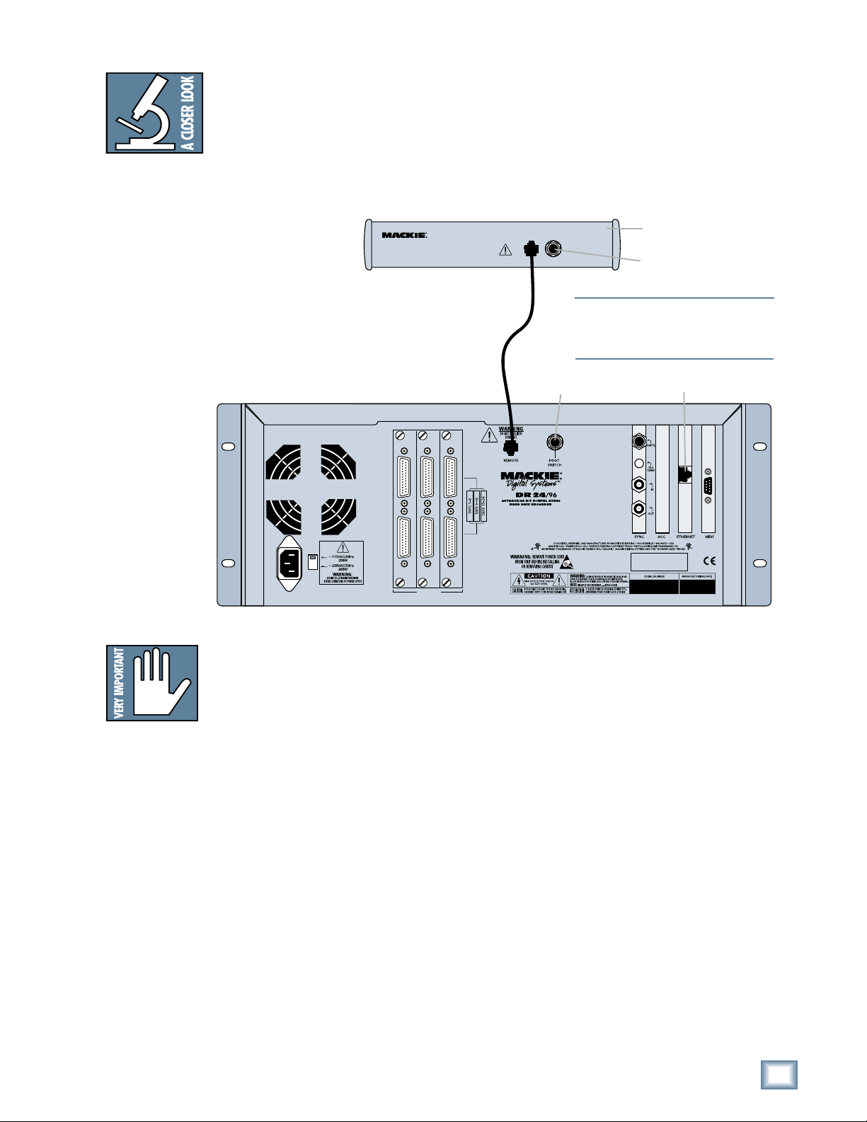
Remote 24 / Remote 48 (Optional)
Installing either remote is as simple as plugging in a telephone. Connect one end
of the cable (supplied with the Remote) to the ‘REMOTE’ jack on MDR24/96 rear
panel, and the other end to the ‘TO HDR REMOTE JACK’ jack on the Remote 24,
or to the “TO HDR” jack on the Remote 48. It’s OK to plug or unplug either
Remote with the MDR24/96 powered on. However, if you plug the Remote 48 into
the MDR24/96 while both are powered on, you must power cycle the Remote 48 to
reset the connection.
REMOTE 24
Remote
connection
ANALOG I/O ANALOG I/O ANALOG I/O
WARNING
DO NOT PLUG INTO
ETHERNET
TO HDR/MDR
FOOT SW
REMOTE JACK
Footswitch
Note:Note:
Note: The MDR24/96 ‘REMOTE’ and Eth-
Note:Note:
ernet jacks both accept CAT-5 Ethernet
cables - don’t get them mixed up!
Back panel of the
Mackie Remote 24
Footswitch
Ethernet Jack
Quick Start Guide
Note:Note:
Note: If you are us-
Note:Note:
ing an MDR24/96
with the Mackie
Digital 8•Bus con-
sole, you may need
to turn on the Digi-
tal 8•Bus first. The
Clock I/O on the
D8B prefers not to
see an active signal
at its Word Clock
input when it pow-
ers up.
M
INPUT OUTPUT
INPUT OUTPUT
INPUT OUTPUT
TAPE IN/OUTS
Footswitch (Optional)
For hands-free do-it-yourself punches and other frequently-used functions like
Play/Stop, Punch In/Out and Take Select, connect the cable of a momentary,
normally open footswitch to the ‘FOOT SWITCH’ 1/4" TS jack on the rear panel of
the MDR24/96, the Remote 24, or Remote 48. If you have a Remote installed you
can connect two foot switches, one to the MDR24/96 and one to the Remote. Each
footswitch functions independently of the other. Footswitch functionality is
assigned in the front panel System menu. See the MDR24/96 Technical Reference
Manual for more details.
Power-Up
OK, NOW you can turn it on. Assuming you have already connected the MDR24/96
to your console, power up the MDR24/96 first, then the outboard equipment and
console, and finally the power amplifiers or powered monitors. Audio equipment
tends to generate unexpected clicks and pops when you power it up, so by
powering up your monitoring system last, you’ll save your speakers and your ears.
Before you read the next section, take a quick, self-guided tour of the front panel
display and controls to get a sense of where they are.
Quick Start Guide
13
Page 14
Configuration
Before starting a Project, you will need to configure the MDR24/96 I/O card
options and synchronization parameters. These parameters determine where the
sample clock is coming from, how fast the sample clock runs, and how many bits
are recorded in every sample. Some options, like sample rate and bit depth, will
become “standards” that you won’t need to change very often. The remaining
synchronization options (for time code and video) are covered in detail in the
Technical Reference manual.
MDR 24/96
Note:Note:
Note: The front
Note:Note:
panel display’s back-
light sw it ches off
aft er several min-
utes of inactivity. It’ll
come back on auto-
matically when it’s
needed to display
new information, but
you can revive it at
any time by pressing
either the
<<
(
<) or
<<
>>
(
> ) b ut to n below
>>
Page LeftPage Left
Page Left
Page LeftPage Left
Page Page
RightRight
Page
Right
Page Page
RightRight
the display.
I/O Cards
Only the DIO•8 and PDI•8 cards require special configuration. If you are using
AIO•8 or OPT•8 cards only, you can skip to the next section.
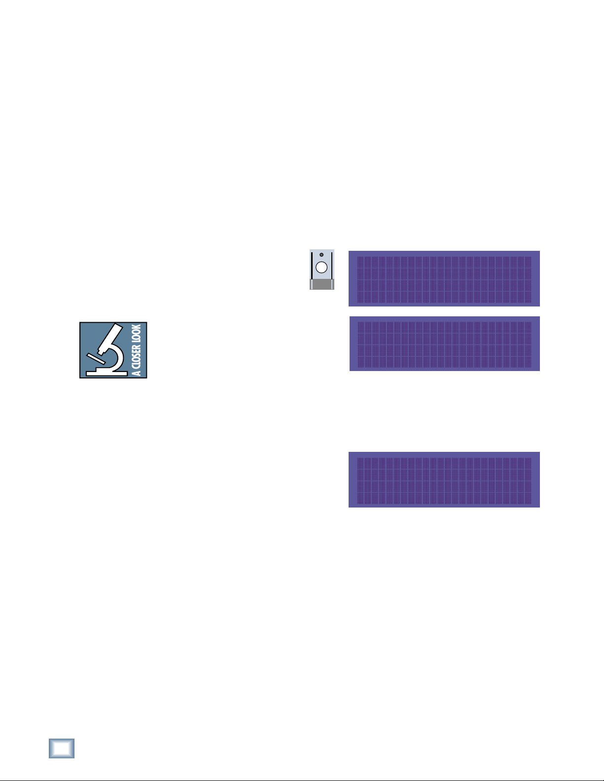
DIO•8 Card
To set the DIO•8 input and output formats:
1. Press Digi I/O to enter
the Digital I/O Card Setup
screen.
2. Select In.
The Setup Tape Inputs screen shows
you the current input settings for
each of the three I/O cards.
3. Press the Select button
corresponding to each DIO•8 card
and toggle the selection between ADAT and TDIF.
4. Press the Page Left (<) button to return to the previous screen.
5. Now select Out.
The Setup Tape Outputs screen
shows you the current output
settings for each of the three I/O
cards.
6. For each DIO•8 card present,
press the Select button to select the desired output format. Or, select
the TD–>AD or AD–>TD option to convert between formats, bypassing
the MDR24/96 tape signal path entirely.
7. When done, press Digi I/O to exit the menu.
DIGI-I/O
DIGITAL I/O Card Setup
Stat Rate
In Out Bits Convert
(SETUP TAPE INPUTS)
1-8 9-16 17-24
ADAT ADAT ADAT
(SETUP TAPE OUTPUTS)
1-8 9-16 17-24
ADAT ADAT ADAT
14
MDR 24/96
Page 15

PDI•8 Card
The PDI•8 card options include sample rate conversion for each stereo AES/EBU
input, and status bit control (pro/consumer mode) for each output. When a PDI•8
card is first installed, its default settings are for sample rate conversion Off, and
channel status bits set to indicate the Pro (AES/EBU) format. In most
circumstances you won’t need to change these settings. However, if the device(s)
connected to the PDI•8 inputs cannot be made a clock master or slave (such as a
CD player with a digital out), enabling sample rate conversion on each affected
input will effectively re-clock the incoming data.
Occasionally you’ll run across a device that will not recognize the digital audio
output from the PDI•8 card. Changing the status bits on the affected output(s)
from Pro to Consumer (S/PDIF) may solve the problem.
Remember that with the AES/EBU format, channels come in pairs, so rather than
eight settings, you have four, one for each pair of channels.
To set the PDI•8 card options:
Quick Start Guide
1. Press Digi I/O to enter the
Digital I/O Card Setup
screen.
DIGI-I/O
2. Select Rate Convert. The
Sample Rate Convert screen
shows you the Sample Rate
Conversion settings for inputs 1-8.
DIGITAL I/O Card Setup
Stat Rate
In Out Bits Convert
SAMPLE RATE CONVERT ->
3. Press the Select button
corresponding to the desired input
channel(s) and toggle the selection.
On enables sample rate conversion,
Off disables it (default).
4. Press the Page Right (>) button to scroll to channels 9-16. Repeat the
procedure for channels 9-16 and 17-24. Press Page Left (<) until you
return to the Digital I/O Card Setup screen.
5. Select Stat Bits. The Setup Status
Bits screen shows you the current
Status Bit settings for outputs 1-8.
1-2 3-4 5-6 7-8
ON OFF OFF ON
SETUP STATUS BITS
1-2 3-4 5-6 7-8
6. Press the Select button
corresponding to the desired output
channel(s) to toggle the selection between Pro (default) and Consu.
Pro Pro Pro Consu
7. Press the Page Right (>) button to scroll to channels 9-16. Repeat the
procedure for channels 9-16 and 17-24. Press Digi I/O to exit.
Quick Start Guide
15
Page 16

The PDI·8 is the only
Mackie I/O card that
currently supports
88.2 or 96 kHz opera-
MDR 24/96
tion. Do not operate
the MDR24/96 at
these Sample Rates
with AIO·8, DIO·8, or
OPT·8 cards installed.
See Errata for more
information
You must still select
the MDR24/96’s
Sample Rate even if
it’s slaved to another
device’s clock. If you
don’t set it correctly,
the MDR24/96 time
display will run at
the wrong rate, even
though audio will
play at the right
speed.
Synchronization
Sample Clock
The Sample Clock setting determines the source of the MDR24/96 sample clock.
If the MDR24/96 is a clock master or is not connected to any other digital
device(s), set it to Internal. If the MDR24/96 is a word clock slave, set it to Word
Clock. The Video setting is discussed in the Technical Reference Manual.
Sample Rate
The Sample Rate determines how fast the MDR24/96 sample clock runs. Compact
Disks use a 44.1 kHz sample rate, while some DVD disks use 96 kHz. The video
production folks prefer 48 kHz because their digital video recorders use 48 kHz.
Even though the MDR24/96 supports four Sample Rates, you can only choose
between two at any given time. The range of available rates is determined by the
current Project’s Sample Rate mode. The Sample Rate mode determines whether
a Project will be a 24-track 44.1 kHz or 48 kHz Project, or a 12-track 88.2 kHz
or 96 kHz Project. To change the Sample Rate to a setting that is not available,
first create or open a Project with the desired Sample Rate mode.
Bit-Depth
The Bit Depth setting determines how many bits are contained in each audio
sample recorded to disk (the bit “resolution”). While 16-Bit audio takes up 1/3
less disk space than 24-Bit audio, 24-Bit audio offers the potential for greater
dynamic range (the difference between the softest and loudest sounds that can be
recorded) and captures a more accurate “image” of the sound.
Word Clock Divisors (88.2/96 kHz operation only)
Some devices that support double-wide AES at 88.2 and 96 kHz can only transmit
or receive word clock at 0.5x the Sample Rate. The Word Clock divisors determine
whether Word Clock In and Word Clock Out run at 1x or 0.5x the MDR24/96
Sample Rate. Both divisors can be set independently.
To configure the MDR24/96 synchronization settings:
1. Press Sync to enter the Sync Options menu. Select Sample Clock. Select
either Internal or Word Clock according to your setup using the (–)Dec /
(+)Inc or << / >> buttons.
2. Select OK to return to the
Sync Options menu.
SYNC OPTIONS [1]->
16
MDR 24/96
3. Select Sample Rate. Using
the (–)Dec / (+)Inc or << /
>> buttons, set the Sample
Rate to 44.1 kHz or 48
kHz (88.2 kHz or 96 kHz). Select OK.
4. Move to the third page of the Sync Options menu with the Page Right (>)
button.
5. Select Bit Depth. Set the Bit
Depth to 16 Bit or 24 Bit using
the (–)Dec / (+)Inc or << / >>
buttons. Select OK.
SYNC
Sample Time Code
Clock Rate Source Rate
<- SYNC OPTIONS [3]
Bit Generate TC
Depth SMPTE MTC Offset
Page 17

Sync Settings for 88.2/96 kHz operation only:
1. Move to the last page of the Sync
Options menu with the Page Right
(>) button. Select SR/2 In.
2. Set the Word Clock Input divisor to
On or Off using the (–)Dec / (+)Inc
or << / >> buttons. Off selects 1x
operation, On selects 0.5x operation.
3. Select OK, then Select SR/2 Out and
set the Word Clock Output divisor to
On or Off.
4. Select OK and press the Sync button to exit the menu.
Quick Start Guide
<- SYNC OPTIONS [4]
Video SR/2 SR/2
Field In Out
SAMPLE RATE/2 OUT
ON
<< >> OK
Quick Start Guide
17
Page 18

MDR 24/96
Hookups
This section shows how the MDR24/96 is typically connected to both analog and
digital consoles (using the Mackie Analog and Digital 8•Bus consoles as
examples). These examples assume that the rest of your studio equipment
(monitors, sound sources, outboard processing, etc.) is already connected, or that
you know how to connect it.
Before you begin, note how the three eight-channel I/O cards are arranged on the
MDR24/96 rear panel: 1-8 is on the left, 9-16 is in the center, and 17-24 is on the
right. Labeling each cable before you begin will make connecting the MDR24/96 to
your console easier.
Note:Note:
Note: If you are us-
Note:Note:
ing a D8B console
with either DIO•8,
PDI•8, or OPT•8
cards installed, then
a Clock I/O card
must also be in-
stalled in the D8B to
properly synchro-
nize its word clock
with the MDR24/96.
The specific hookups for each MDR24/96 I/O card are shown below.
Analog Hookup (AIO•8)
This example describes the hookup for the 24•8 analog console.
Cables & Hardware
(3) AIO•8 cards for MDR24/96
(6) Analog snakes, DB25 to eight 1/4” TRS phone plugs
Hookup
1. Connect three snakes to the MDR24/96 Inputs (bottom connector). If you
want to have the ability to route any console input to any recorder track,
then connect the 1/4” plugs on each of the three snakes to the likenumbered Submaster / Tape Output jacks on the 8•Bus console. This
works as long as you don’t record more than 8-channels at a time, since
the Submaster Outputs 9-16 and 17-24 are the same as outputs 1-8.
Alternately, you can connect the console’s direct outputs to the recorder’s
inputs, so that each console channel feeds the like-numbered recorder
track. Or, you can use a combination of direct and subgroup outs. The
hookup diagram below shows the MDR24/96 inputs connected to the
Submaster Outputs.
18
MDR 24/96
MDR24/96 back panel
ANALOG I/OANALOG I/OANALOG I/O
INPUT OUTPUT
INPUT OUTPUT
INPUT OUTPUT
120VAC
50/60 Hz 475W
TAPE IN/OUTS
1-8 9-16 17-24
ANALOG I/O ANALOG I/O ANALOG I/O
INPUT OUTPUT
INPUT OUTPUT
TAPE IN/OUTS
MDR24/96 AIO Cards
SYNC ACC ETHERNET MIDI
INPUT OUTPUT
87156145
16
7531
64 28
13 11 9
15
16 14 12 10
19
21
23
20
22
24
4123112101
13
9
171820 1921222324
TAPE RETURNS 1-8
TAPE RETURNS 9-16
17
TAPE RETURNS 17-24
18
24•8 SUBMASTER
/ TAPE OUTPUTS
Page 19

TAPE IN/OUTS
INPUT OUTPUT
INPUT OUTPUT
INPUT OUTPUT
ANALOG I/O ANALOG I/O ANALOG I/O
2. Connect three snakes to the MDR24/96 Outputs (top connector). Connect
the plug end of the snakes to the like-numbered Tape Return jacks on the
24•8 console.
MDR24/96 Settings
1. Set the Sample Clock to Internal.
2. Set the Sample Rate and Bit Depth according to your preference.
Console Settings
Set the 24•8 console to the nominal +4 dBu operating level by setting the
five Operating Level switches in the Sub Out and Tape Return sections to the
‘out’ position.
This example describes the hookup for the D8B console equipped for analog I/O.
Quick Start Guide
Note:Note:
Note: Some older
Note:Note:
AIO•8 cards have
the Input jack la-
beled as “From
Tape” and the Out-
put jack labeled as
“To Tape.” Otherwise, they operate
identically. Sigh ...
long story.
AIO•8 Cards
MDR 24/96
ANALOG I/O ANALOG I/O ANALOG I/O
INPUT OUTPUT
INPUT OUTPUT
TAPE IN/OUTS
INPUT OUTPUT
(6) DB25 to
DB25 Analog
Snakes
Digital 8•Bus
Cables & Hardware
(3) AIO•8 cards for MDR24/96
(3) AIO•8 cards for D8B
(6) DB25 to DB25 analog snakes
Hookup
1. Connect three snakes between the MDR24/96 Inputs (bottom connector)
and the corresponding D8B Tape Outputs (top connector).
AIO•8 Cards
2. Connect three snakes between the MDR24/96 Outputs (top connector)
and the corresponding D8B Tape Inputs (bottom connector).
MDR24/96 Settings
1. Set the Sample Clock to Internal.
2. Set the Sample Rate and Bit Depth according to your preference. It is
not necessary to set the D8B and MDR24/96 to the same Sample Rate,
since with analog connections, the sample clocks on the two units are not
synchronized
Console Settings
1. Set the D8B Sample Clock to 44.1 k Internal or 48 k Internal according
to your preference.
Quick Start Guide
19
Page 20

TDIF Hookup (DIO•8)
Cables & Hardware
(3) DIO•8 cards for MDR24/96
(3) DIO•8 cards for D8B
(1) Clock I/O card for D8B
(3) TDIF cables
(1) 75 Ω BNC word clock cable
MDR 24/96
NoteNote
Note: Determining
NoteNote
which unit in
provides the master
clock depends on your
application. For information on advanced
applications, see the
Applications Manual.
Figure 1
Hookup
1. Connect the three TDIF cables between the corresponding TDIF jacks on
the MDR24/96 and D8B.
2. When TDIF is used, the D8B must have a Clock I/O card installed. To
make the D8B the clock master, connect its Word Clock Out (not DIO•8
Sync out) to the MDR24/96 Word Clock In. To make the MDR24/96 the
clock master, connect its Word Clock Out to the D8B Word Clock In.
See Figure 1.
MDR24/96 Settings
1. Set the Tape Input format for each DIO•8 card to TDIF, and the Tape
Output format to TDIF.
2. If the MDR24/96 is the clock master, set the Sample Clock to Internal;
if it is a clock slave, set it to Word Clock and depress the 75 Ω
termination switch on the Sync card.
3. Set the Sample Rate to 44.1 kHz or 48 kHz according to your
preference.
Console Settings
1. Set the Tape Input and Tape Output format for each DIO•8 card to TDIF.
2. If the D8B is the clock master, set the Sample Clock to either 44.1 k
Internal or 48 k Internal; if it is a clock slave, set the Sample Clock to
either 44.1 kHz or 48 kHz. Set the Sample Rate to match the Sample
Rate selected on the MDR24/96.
20
MDR 24/96
Page 21

Apogee
Clock I/O
Card
Word
Clock Out
TDIF Hookup with DIO•8
APOGEE
SYNC
Word
Clock
DIGITAL I/O
Out
APOGEE
APOGEE
DIGITAL I/O
TDIF
APOGEE
DIGITAL I/O
TDIF
TDIF
Quick Start Guide
DIO•8 Cards
TDIF Connection
Clock Out
(MDR24/96
as Master)
Depress the
Termination
button if the
MDR24/96 is set
to Slave
Word
Word
Clock In
Word
Clock Out
(D8B as
Master)
Use one
only
Word
Clock In
MDR
Sync
Card
APOGEE
Word
Clock
In
ADAT OPTICAL
APOGEE
DIGITAL I/O
ADAT OPTICAL
IN OUT
SYNC
DIGITAL I/O
TDIF
IN OUT
SYNC
ADAT OPTICAL
APOGEE
ADAT OPTICAL
IN OUT
SYNC
APOGEE
DIGITAL I/O
TDIF
IN OUT
SYNC
ADAT OPTICAL
ADAT OPTICAL
IN OUT
SYNC
TDIF
IN OUT
SYNC
TDIF Cables
(DB25)
TDIF Connection
DIO•8 Cards
Digital 8
•Bus
MDR 24/96
Note:Note:
Note: The Word Clock
Note:Note:
connections shown
here are the same for
Figure 2, 3 and 4.
Word
Clock Out
Figure 1
Quick Start Guide
21
Page 22

ADAT Optical Hookup (DIO•8 or OPT•8)
Cables & Hardware
(3) DIO•8 or OPT•8 cards for MDR24/96
(3) DIO
(1) Clock I/O card for D8B
(6) ADAT Optical cables
(1) 75Ω BNC word clock cable
•8 or OPT•8 cards for D8B
MDR 24/96
Note:Note:
Note: Determining
Note:Note:
which unit in
provides master
2 & 3
clock depends on
your application. For
information on ad-
vanced applications,
see the Technical
Reference manual.
Figures
Hookup
1. Connect three ADAT Optical cables from the MDR24/96 Optical Outputs to
the Optical Inputs on the corresponding D8B I/O cards.
2. Connect three ADAT Optical cables from the MDR24/96 Optical Inputs to
the Optical Outputs on the corresponding D8B I/O cards.
3. When ADAT Optical is used, the D8B must have a Clock I/O card
installed. To make the D8B the clock master, connect its Word Clock Out
to the MDR24/96 Word Clock In. To make the MDR24/96 the clock
master, connect its Word Clock Out to the D8B Word Clock In.
MDR24/96 Settings
1. If you have DIO•8 cards installed, set the Tape Input and Tape Output
format for each card to ADAT. OPT•8 cards need no configuration.
2. If the MDR24/96 is the clock master, set the Sample Clock to Internal; If
the MDR24/96 is a clock slave, set the Sample Clock to Word Clock and
depress the 75Ω termination button on the Sync card.
3. Set the Sample Rate to 44.1 kHz or 48 kHz according to your preference.
Console Settings
1. If you have DIO•8 cards installed, set the Tape Input and Tape Output
format for each card to ADAT. OPT
2. If the D8B is the clock master, set the Sample Clock to either 44.1 k
Internal or 48 k Internal; if it is a clock slave, then set the Sample Clock
to either 44.1 kHz or 48 kHz. Set the Sample Rate to match the Sample
Rate selected on the MDR24/96.
•8 cards need no configuration.
22
MDR 24/96
Page 23

Apogee
Clock I/O
Card
Word
Clock Out
ADAT Optical Hookup with DIO•8
APOGEE
SYNC
Word
Out
Clock
APOGEE
APOGEE
DIGITAL I/O
APOGEE
DIGITAL I/O
TDIF
APOGEE
DIGITAL I/O
TDIF
DIO•8 Cards
TDIF
ADAT Optical Out
Quick Start Guide
Digital 8 Bus
ADAT Optical In
Clock Out
(MDR24/96
as Master)
Depress the
Termination
button if the
MDR24/96 is set
to Slave
Word
Word
Clock In
Word
Clock Out
(D8B as
Master)
Use one
only
Word
Clock In
Word
Clock Out
MDR
Sync
Card
Word
Clock
In
ADAT OPTICAL
APOGEE
DIGITAL I/O
ADAT OPTICAL
IN OUT
SYNC
APOGEE
DIGITAL I/O
TDIF
IN OUT
SYNC
ADAT OPTICAL
ADAT OPTICAL
IN OUT
ADAT OPTICAL
SYNC
APOGEE
DIGITAL I/O
TDIF
IN OUT
ADAT OPTICAL
SYNC
DIO•8 Cards
IN OUT
SYNC
TDIF
MDR 24/96
IN OUT
ADAT Optical Out
SYNC
ADAT Optical In
Figure 2
Quick Start Guide
23
Page 24

ADAT Optical Hookup with OPT•8
MDR 24/96
Word
Clock Out
(MDR24/96
as Master)
Depress the
Termination
button if the
MDR24/96 is set
to Slave
Apogee
Clock I/O
Card
Word
Clock Out
Word
Clock In
Word
Clock Out
(D8B as
Master)
Use one
only
APOGEE
SYNC
MDR
Sync
Card
Word
Clock
APOGEE
Word
Clock
OPT•8 Cards
ADAT Optical Out
Out
Digital•8 Bus
ADAT Optical In
In
ADAT Optical Out
MDR 24/96
24
MDR 24/96
Word
Clock In
Word
Clock Out
ADAT Optical In
OPT•8 Cards
Figure 3
Page 25

Note:Note:
Note: Determining
Note:Note:
which unit in
your application. For
information on ad-
vanced applications,
Reference manual.
Figure 4
provides master
clock depends on
see the Technical
AES/EBU Hookup (PDI•8)
Cables & Hardware
(3) PDI•8 cards for MDR24/96
(3) PDI•8 cards for D8B
(1) Clock I/O card for D8B
(3) DB25 to DB25 AES/EBU snakes
(1) 75Ω BNC word clock cable
Hookup
1. Connect the three AES/EBU cables between the corresponding AES/EBU
connectors on the MDR24/96 and D8B.
2. When AES/EBU is used, the D8B must have a Clock I/O card installed. To
make the D8B the clock master, connect its Word Clock Out to the
MDR24/96 Word Clock In. To make the MDR24/96 the master, connect its
Word Clock Out to the D8B Word Clock In.
MDR24/96 Settings
1. If the MDR24/96 is the clock master, set the Sample Clock to Internal; if
it is a clock slave, set the Sample Clock to Word Clock and depress the
ΩΩ
75
Ω termination switch on the Sync card.
ΩΩ
2. Set the Sample Rate to 44.1 kHz or 48 kHz according to your preference.
Console Settings
1. If the D8B is the clock master, set the Sample Clock to either 44.1 k
Internal or 48 k Internal; if it is a clock slave, set the Sample Clock to
either 44.1 kHz or 48 kHz. Set the sample rate to match the Sample Rate
selected on the MDR24/96.
Quick Start Guide
OK, so we fibbed a little. You can use PDI•8 cards in the D8B without a Clock I/O
card installed, but doing so requires that you enable sample rate conversion on
both the D8B and the MDR24/96 in lieu of word clock synchronization. Sample
rate conversion results in a 4-bit loss in sample resolution that may degrade
the quality of the sound slightly. So, the moral of the story is that unless you
just blew your wad on a new guitar and are eating peanut butter sandwiches
until your next paycheck, go buy a Clock I/O card.
Quick Start Guide
25
Page 26

AES/EBU Hookup with PDI•8
MDR 24/96
Depress the
Termination
button if the
MDR24/96 is set
to Slave
Word
Clock Out
(MDR24/96
as Master)
Apogee
Clock I/O
Card
Word
Clock Out
Word
Clock In
Word
Clock Out
(D8B as
Master)
Use one
only
APOGEE
SYNC
MDR
Sync
Card
Word
Clock
APOGEE
Word
Clock
PDI•8 I/O Cards
PDI•8
PDI•8
PDI•8
Out
Digital 8•Bus
AES/EBU I/O
AES/EBU I/O
AES/EBU I/O
In
AES/EBU
Cables (DB25)
PDI•8
PDI•8
PDI•8
MDR 24/96
AES/EBU I/O
AES/EBU I/O
AES/EBU I/O
26
MDR 24/96
Word
Clock In
Word
Clock Out
PDI•8 I/O Cards
Figure 4
Page 27

Note: Note:
Note: The front
Note: Note:
panel display
blanks after several
minutes of being
idle. Pressing any
button below the
display will turn it
back on.
Quick Start Guide
MDR24/96 Operation
Now that you’ve finished installing and configuring the MDR24/96, you’re almost
ready to start your first Project. We still want you to read this entire guide, but we
already hear some of you shuffling and muttering. Okay, okay, okay... for the
terminally impatient, read this chapter, then you can go out and play with your
friends.
This section explains all you need to know to run a basic recording session:
opening and creating Projects, operating the Transport, setting levels, and
recording and overdubbing tracks. After you’re done recording, you will learn how
to back up your project to Mackie Media M•90 and Mackie Media PROJECT
drives.
Because this section just touches on the basics of MDR24/96 operation, we
strongly recommend going through the Technical Reference manual to learn about
advanced MDR24/96 features like, Virtual Takes, FTP file transfer,
synchronization, and more.
Opening Projects
The MDR24/96 organizes audio files and session information into folders called
Projects. When the MDR24/96 boots up, it automatically opens the last Project
you worked on. We’ve included two demonstration Projects, Ode to Masters and
Little Bit of Love, to help you get familiar with the MDR24/96 right out of the box.
At this point, you should see the name of the demo Project in the LCD display.
To open a Project:
1. Press Project. In the Project
Files Menu, select Open.
2. Choose the drive you want to
open the Project on by selecting
either Internal or External from
the Select Source Drive screen
using the (–)Dec / (+)Inc or << /
>> buttons. The selection
defaults to the drive containing
the currently open Project. Press
Next.
3. Use the (–)Dec / (+)Inc or the
<< / >> buttons to select the
desired Project, then select Open.
Note: Note:
Note: The front panel display blanks after
Note: Note:
several minutes of being idle. Pressing any
button below the display turns back on.
PROJECT MENU [1]->
New Open Save Delete
Select Source Drive
Internal
<< >> NEXT
Quick Start Guide
27
Page 28

Basic Transport Operations
The MDR24/96 transport and recording controls are similar to those on most
multitrack tape recorders.
Play
Play puts the MDR24/96 into play from any state (as if you didn’t know).
Play also punches out of record and cancels master record standby while
leaving the Transport in play.
MDR 24/96
To put the Transport into play:
♦
Press Play.
REWIND
FAST FWD
STOP
PLAY
RECORD
Fast Wind
Rewind and Fast Forward put the MDR24/96 into fast wind mode from any
state. They behave just like those on a large multitrack recorder – when
pressed from stop, the “tape” rolls slowly at first, then accelerates to 20X
speed in a few seconds. Pressing either button a second or third time
increases the winding speed still further.
To put the Transport into fast wind:
♦
Press Rewind or Fast Forward one, two, or three times.
Stop
Stop brings the “tape” to an immediate halt. Stop also punches out of record
and cancels master record standby.
To stop the Transport:
28
MDR 24/96
♦
Press Stop.
Time Display
MDR 24/96 Front Panel
MINUTESHOURS
BARS
SECONDS FRAME S
BEATS
TICKS
The Current Time display shows the exact position of the MDR24/96’s
“playback head”. Current Time is displayed in SMPTE time
(HH:MM:SS:Frames).
To change the Current Time:
♦
Use the Transport Play, Rewind, Fast Forward or Loc buttons.
Current Time Display
Page 29

Locate Points and Looping
Locate points provide fast access to frequently used locations in your Project.
The MDR24/96 has two numbered Locates (two additional numbered Locates
are availible when using the Remote 24 or Remote 48). Storing a Locate point
saves the Current Time (Transport position) to the Locate button. Recalling a
Locate causes the Transport to jump to the stored time.
To recall a Locate point:
♦
Press Loc 1 or Loc 2 to jump to that point.
LOC 2LOC 1
To store numbered Locate points:
Locate points can be stored either on the fly or when stopped.
1. Press Store. The Store light will blink to indicate that the MDR24/96
is ready to save a Locate point.
2. Press Loc1 or Loc 2 when the Transport is at the
desired time; the Store light will go out, indicating that
the point has been stored.
Locates 1 and 2 double as start and end points for looped playback. When
looping is enabled, playback cycles between the Loop Start and Loop End
points. The order of the Loop points does not matter. If Current Time is
outside the Loop points when playback starts, the transport jumps to the Loop
Start point; if it is between the Loop points, playback starts from Current
Time.
LOC 2LOC 1 STORE
Quick Start Guide
To enable Looping:
1. Press Loop 1-2 to enable looping.
2. Press Play to start loop playback.
LOOP
1–2
Quick Start Guide
29
Page 30

MDR 24/96
P
TRACK EDIT MENU [1]->
Undo Cut Copy Paste Redo
Track Editing
The MDR24/96 features non-destructive Cut, Copy, and Paste editing.
Edit operations are performed on an "Area" defined by the range of time
between the Start and End points on selected track(s). Edit operations
are remembered in a 999-level History List so that every edit can be undone
and redone.
To perform an edit:
1. First press the
Track/Edit button,
then the button of
the desired edit
operation. The
Record Ready
LEDs change to indicate
which Tracks are selected.
2. Press the Record Ready button(s)
corresponding to the Track(s) you
wish to edit.
TRACK/
EDIT
REC REC REC
321
3. Press the Start and End buttons to
define the range of time you wish to
edit. You can set the Start and End
points in any Transport State.
4. Press the desired edit button. You
cannot execute edit operations
while the Transport is moving.
5. After the edit operation, the Record Ready buttons and LEDs return
to their previous state.
START:00:02:17:12
END:00:02:20:04
(trackselect = record)
Start End Cut Join
Cut / Join
Cut cuts a "hole" in the selected Area
and copies the Area to the
Clipboard. Join performs a Cut and
then slides everything that occurs
after the End point forward in time to
fill the "gap" left buy the Cut, exactly
like splicing two ends of tape
together.
Copy
Copy copies the selected Area to the
Clipboard, but leaves the Project
unaffected.
START:00:02:17:12
END:00:02:20:04
(trackselect = record)
Start End Cut Join
START:00:02:17:12
END:00:02:20:04
(trackselect = record)
Start End Cancel Copy
SELECTSELECTSELECT
SELECT
Paste / Insert
Paste copies the contents of the
Clipboard Area into the Project
starting at the Start point and first
selected track. All audio in the
Clipboard replaces any existing
audio, and any blank space in the
Clipboard leaves existing audio
unaffected. Insert splits the affected Area at the Start point and slides the
30
MDR 24/96
audio back in time to make a "hole" for the Clipboard. If the clipboard Area
START:00:02:17:12
(trackselect = record)
Start Paste Insert
Page 31

B
undo:Paste
redo:Copy
#:32 Undo Redo Exit
contains multiple tracks, the first track in the clipboard is placed onto the first
selected Track, and the remaining Tracks in the clipboard follow in order.
Quick Start Guide
Undo / Redo
Undo and Redo allow you to step
forward and backwards through your
editing changes. The History List
number lets you keep track of your
changes so that you can easily do A/B
comparisons of different edits.
Undo Current
Command
The History List
Number
Redo Prior
Command
Creating Projects
Now that you have a few basics down, you’re ready to start recording. First, you’ll
need to create a new Project. Typically a Project is a song, radio spot, or sound
effects stem for a 10-minute film reel, but it could also be a live concert or an
entire symphony.
To create a new Project:
1. Press Project, then
select New. The
MDR24/96 asks if you
want to save the
currently open Project.
Press No to discard the
changes you may have made to
the demo Project.
PROJECT
PROJECT MENU [1]->
New Open Save Delete
2. Choose the drive you want to
3. Select either 44.1/48K or
4. The name “Project#1” appears
Select Source Drive
create the Project on by
selecting either Internal or
External from the Select
Destination Drive screen using
the (–)Dec / (+)Inc or << / >>
buttons. The selection defaults
to the drive containing the currently open Project. Press Next.
88.2/96K from the Sample
Rate Mode screen using the
(–)Dec / (+)Inc or << / >>
buttons. The Sample Rate
mode determines whether
your project will be a 24track Project at 44.1 or 48
kHz, or a 12-track Project at 88.2 or 96 kHz. Once a Project is created the
Sample Rate mode cannot be changed. Press Next.
on the left side of the LCD
screen. A pointer (“v”) appears
above the first character of the
name to indicate that you can
change that character. Press the
(–)Dec / (+)Inc buttons to select
the character you want in that position. Select the >> button to move the
pointer to the next character.
Internal
<< >> NEXT
Sample Rate Mode
44.1/48K
<< >> NEXT
Enter A Project Name:
v
Project#1
<< >> New Cancel
Quick Start Guide
31
Page 32

5. When you’ve completed
the Project name, select
New to create the
Project and exit.
PROJECT: Project#1
PLAYLIST: Playlist 1
DRIVE: C:Internal
AVAIL: 01:35:00
Your new project is now
open; the Active Drive, Project Name, and Playlist Name are shown in the
LCD display and in the GUI above the Current Time display.
MDR 24/96
In the MDR24/96 and HDR24/96, Playlists are that part of a Project that keeps track of all of your recording and editing, and controls what you hear when you hit Play. The HDR24/96 supports multiple Playlists
while the MDR24/96 supports only one. If an HDR24/96 Project is played back on the MDR24/96, the
MDR24/96 will play back the last Playlist saved in the HDR24/96 Project.
Monitoring
The Monitor Mode buttons determine what you hear from the MDR24/96 Tape
Outputs. The MDR24/96 offers several familiar monitoring modes to facilitate
rehearsal, tracking, and overdubbing.
All Input
All Input is used for rehearsal and level setting. When All Input is on, both
armed and unarmed tracks monitor their inputs, and the Auto Input setting
has no effect.
To enable All Input:
♦
Press the All Input button. The LED above the
button when All Input is on.
Auto Input
Auto Input is used for recording. Auto Input affects only tracks that are in
Record Ready (“armed”). Tracks that are not armed only monitor the
playback of previously recorded audio. All Input overrides Auto Input. To use
Auto Input, All Input must be turned off.
INPUT
ALL
32
MDR 24/96
When Auto Input is On, armed tracks monitor their inputs in Stop, Fast
Forward, Rewind, and Record. In Play, you hear only what’s already recorded
on the tracks. This mode is used primarily for tracking and overdubbing,
where you want to hear what’s been previously recorded on the track before
the punch-in and after the punch-out. During the punch, you hear what is
presently being recorded. Auto Input On is the default mode when you power
up the MDR24/96.
When Auto Input is Off, armed tracks always monitor their inputs. This mode
is used primarily for rehearsal and tracking, where you want to always hear
what you’re playing rather than what’s already recorded on that track.
To enable Auto Input:
♦
Press the Auto Input button. The
glowing LED above the button
indicates that it’s ON.
AUTO
INPUT
Page 33

Metering and Setting Record Levels
A professional analog recorder has meters that indicate 0 VU at a +4 dBu nominal
signal level. Generally you can record peaks 10 to 15 dB above that before
distortion becomes objectionable. This 10-15 dB range above the nominal level is
called “headroom”. The overload indicators on the MDR24/96 light when the
signal level reaches –1 dBFS.
On digital recorder meters, zero represents the full-scale digital signal level, 0
dBFS for short. 0 dBFS is the hottest signal that a digital device can handle, with
no headroom to spare. When a digital signal reaches 0 dBFS for more than a
sample or two, the resulting distortion is uglier than scraping your fingernails
across a chalkboard.
24TRACK/24BIT DIGITAL AUDIO HARD DISK RECORDER
OL
OL
OL
OL
OL
OL
OL
OL
OL
OL
OL
OL
OL
OL
OL
OL
OL
OL
OL
OL
OL
OL
OL
2
2
4
4
7
7
10
10
15
15
20
20
25
25
30
30
35
35
40
40
50
50
2
2
2
4
4
4
7
7
7
10
10
10
15
15
15
20
20
20
25
25
25
30
30
30
35
35
35
40
40
40
50
50
50
2
2
2
4
4
4
7
7
7
10
10
10
15
15
15
20
20
20
25
25
25
30
30
30
35
35
35
40
40
40
50
50
50
2
2
2
4
4
4
7
7
7
10
10
10
15
15
15
20
20
20
25
25
25
30
30
30
35
35
35
40
40
40
50
50
50
2
2
2
4
4
4
7
7
7
10
10
10
15
15
15
20
20
20
25
25
25
30
30
30
35
35
35
40
40
40
50
50
50
2
2
2
4
4
4
7
7
7
10
10
10
15
15
15
20
20
20
25
25
25
30
30
30
35
35
35
40
40
40
50
50
50
2
2
2
4
4
4
7
7
7
10
10
10
15
15
15
20
20
20
25
25
25
30
30
30
35
35
35
40
40
40
50
50
50
Remember, audio levels must NEVER reach 0 dBFS... never, ever, ever. Digital
clipping is an extremely nasty sound that could only pass for music if you
like what those crazy kids listen to over and over at all hours of the night including weekdays.
2
2
2
4
4
4
7
7
7
10
10
10
15
15
15
20
20
20
25
25
25
30
30
30
35
35
35
40
40
40
50
50
50
242322212019181716151413121110987654321
Quick Start Guide
To get the get the best sound from the MDR24/96:
1. Turn All Input on.
ALL
INPUT
2. Ask the talent to play or sing as loud as they will be performing during the
session. While watching the MDR24/96 meters, adjust the console’s tape
outputs so that the signal peaks cause the red overload indicators to come
on occasionally. Then, back off the tape output level slightly. This insures
the best fidelity and the widest dynamic range in the recorded signal and
leaves you a little headroom to accommodate the talent’s enthusiasm.
Keep the signal levels as high as possible without overload, because
recording at lower levels reduces resolution and dynamic range.
Nonetheless it is always better to be conservative and avoid the risk of
overload than to try squeezing the last ounce of dynamic range from the
signal.
3. Alternately, if you have a tone generator or a sound source with a constant
volume (you can hold down a key on a synth), turn All Input on and send
the tone to all 24 tracks of the console. Adjust the output levels to read 0
VU on analog consoles, or around –20 dBFS on digital consoles. If the
MDR24/96 meters read -15 to -20, you’re in good shape. This leaves
enough headroom for most popular music, but if you’re recording acoustic
music, jazz, classical, or narration, you may want to leave a little more.
When the talent starts to play you may have to make some final tweaks to
get everything just right.
Quick Start Guide
33
Page 34

MDR 24/96
OL
2
50
4
7
10
15
20
25
30
35
40
+22 dBu
dBu
equivalent
+20
–28 dBu
+18
+15
+12
+7
+2
–3
–8
–13
–18
4. After adjusting the tape output levels for each console channel, follow
your console manufacturer’s instructions for setting the console tape
return levels.
With analog I/O, a +22 dBu signal at the
MDR24/96 inputs and outputs corresponds to
0 dBFS inside the MDR24/96. So, if your
console has a nominal output level (0 VU) of
+4 dBu, there is 18 dB of headroom before
you hit the maximum record level on the
MDR24/96. It also means that your console
must be capable of putting out at least +22
dBu without distortion so the console doesn’t
clip while the recorder is still within its
working range. Most professional consoles
can output +22 dBu without breaking a sweat
(like the Mackie Analog and Digital 8•Bus consoles). But beware that
semi-pro consoles often operate at a nominal output level of –10dBV and
will run out of steam before reaching a level that can take advantage of the
recorder’s full resolution.
Recording
All recording in the MDR24/96 is non-destructive. When you record over existing
audio, the old audio is not “erased” as it with magnetic tape; rather, new audio
files are created in addition to the existing files.
Recording can only take place on tracks that are “armed” for recording.
To arm tracks for recording:
1. Press a track’s Record Ready button.
2. Press it again to disarm the track.
The Record Ready LED/button blinks when a track is armed and ready to record,
and glows when the track is recording.
REC
1
To record:
1. Arm one or more tracks.
2. Press Play and Record simultaneously.
3. Press any Transport button other than
Record to stop recording.
The Record LED glows when the MDR24/96 is recording and blinks when Record
is engaged with no tracks armed (master record standby mode).
34
MDR 24/96
PLAY
RECORD
Page 35

Footswitch Operation
Using a footswitch with the MDR24/96 gives you hands-free access to two of the
most-used MDR24/96 functions. The footswitch is extremely handy when you
want to use your hands for other tasks, like playing your instrument, working the
console, or eating pizza.
Punch punches in just like pressing Play+Record and punches out like
pressing Play. When playing, hitting the footswitch punches in on all armed
tracks. When recording, hitting the footswitch again punches out of Record,
but leaves the transport in Play.
Stop/Play toggles the MDR24/96 between Stop and Play. When the
Transport is stopped, it puts it into play; when moving, it stops the Transport.
To assign the footswitch function:
1. Press the System button. In the System menu, select Footswitch MDR.
Then select Punch, Stop/Play from the MDR24/96 Footswitch mode menu.
2. Select OK, and press System again to exit.
Footswitch
Quick Start Guide
ANALOG I/O ANALOG I/O ANALOG I/O
INPUT OUTPUT
INPUT OUTPUT
TAPE IN/OUTS
M
INPUT OUTPUT
Quick Start Guide
35
Page 36

MDR 24/96
B
P
Delete Last
With the MDR24/96 you don’t need to worry about filling up your hard disks with
unwanted takes. The Delete Last function permanently erases all the audio files
recorded during the last record pass. A recording pass consists of all punches
made within one play/stop cycle. If you make edits after doing a record pass,
Delete Last will have no effect.
To delete the last recording pass:
♦
Press the Delete Last button. The LCD display
will ask you to confirm that you want to delete
the last record pass. Press OK.
DELETE LAST
Alternate method:
1. Press the Track/
Edit button and
select Undo-Redo.
2. From the UndoRedo menu select Undo.
TRACK/
EDIT
undo:Record Pass
redo:none
#:3 Undo Redo Exit
Redo Prior
Command
Undo Current
Command
The History List
Number
Saving Projects
Every time you record new
audio, the audio data and
Project information is
automatically saved to disk.
However, if you make other
changes to the Project (setting
Locates, editing etc.) without
recording new audio, you must save the Project for these changes to be
remembered. In other words, if you quit without saving, no audio is lost, but your
changes are. So once you start editing, save often.
PROJECT
PROJECT MENU [1]->
New Open Save Delete
36
To save the current Project:
1. Press the Project button.
2. From the Project menu select Save.
3. Press the Project or Page Left (<) button again to exit.
MDR 24/96
Page 37

T
D
Project Backup / Restore
With Mackie Media drives, you can back up your Projects on removable media
that you can hand to the client or store in your tape library. Backing up and
restoring Projects is as simple as copying the Projects between the internal and
the Mackie Media drives.
To copy Projects between the internal and Mackie Media drives:
1. Press the Backup
button.
2. Using the - Dec / + Inc
or the << / >> buttons,
select Set Source to set the drive
the Project will be copied from, and Set Dest to set the drive the Project
will be copied to. Since a Project can’t be copied onto itself, the Source
and Destination drives must be different.
BACKUP
BACKUP SOURCE: Internal
DESTINATION: External
Set
Source Dest Exit Backup
Quick Start Guide
3. Select OK to return to the
Backup menu, then select
Backup. Choose the desired
Project using the (-) Dec / (+) Inc
or the << / >> buttons.
4. Press OK. When the backup is completed, either select another Project to
back up or press the Backup button to exit.
It is extremely important that you make backup copies of your projects at the end
of each session. While digital recording technology is highly reliable and hard disk
media is durable, sometimes stuff just happens. To reduce your risk of catastrophic
data loss (and the possible loss of $$ and clients), back up your projects on two
media before deleting them from your working drive(s).
There…. now you know better. So, don’t wait until disaster strikes to get backup
religion, and don’t complain to Mackie when your pet Rottweiler discovers that the
only copy of your client’s $20,000 project makes a superb chew toy and buries the
drive in the garden.
All media must be formatted before it can be used with the MDR24/96. Formatting
erases the media’s contents and prepares the file system for use with the MDR24/96.
You can format media with the MDR24/96, or use existing FAT16 or FAT32formatted media. Mackie Media M•90 drives come pre-formatted and ready to use,
as do ORB disks for the Mackie Media PROJECT drive (be sure to buy IBM
formatted ORB disks). Most off-the-shelf UDMA IDE drives do not come preformatted.
Select Project to Backup
Eborall Song
<< >> OK Cancel
Although you can use almost any IDE drive for backup, not all UDMA IDE drives
are fast enough to be used for recording and playback. If you want to use your own
UDMA IDE drive for recording and playback, you must format it with the MDR24/96,
then verify that it is fast enough to record and playback at the maximum data rate
(24 track, 24-bit, 48 kHz). If the drive passes the performance verification test, it is
permanently “tagged” as a real-time drive. If it fails, then the drive can be used for
backup only. External drives that fail the record verification test will appear with an
asterisk (*) in the front panel menus and dialogs.
Quick Start Guide
37
Page 38

To format and verify media performance from the MDR24/96:
B
MDR 24/96
1. Press the Disk Util button.
DISK UTILITY MENU
2. Now select Format. The
LCD screen will display a
message asking you to
verify the drive speed for
recording and playback.
3. Select OK. When the format operation has completed, another message
will appear asking you to verify the drive speed for recording and
playback.
4. If a UDMA drive is installed, select OK. After the performance verification
is completed, select Continue. If a Mackie Media PROJECT drive is
installed, select Cancel; they are too slow to be used for recording and
playback.
5. Press Disk Util to exit.
Some UDMA drives cannot keep up with the demand for 24 tracks of audio data.
So, before you rush to your local computer store and buy the cheapest UDMA
drive you can find, consider picking up some Mackie Media drives from your
nearest Mackie dealer instead (nudge nudge, say no more…).
Mount Format Verify
Purge Audio
Purge Audio permanently deletes any audio files that were recorded in the Project
but are no longer used in the Playlist. Whenever you Purge Audio, the History List
is cleared.
To Purge Audio from your hard drive:
1. Press the Project
button, and then the
Page Right (>) to the
second Project menu
page.
2. From the Project Menu select
Purge Audio.
3. Press OK to confirm the operation.
There! You’re all boned up on the MDR24/96, so put down this booklet and get to
work ... or play. Thanks for reading this guide. If questions have gone
unanswered, check the MDR24/96 Technical Reference Manual or Mackie’s
website www.mackie.com. Enjoy!
PROJECT
<- PROJECT MENU [2]
Purge Template
Rename Audio Reset Save
38
MDR 24/96
Page 39

Appendix A: Compatible Cables
Analog and Digital Multitrack Cables
The following companies supply analog and digital multitrack cables for use with
the MDR24/96 I/O cards:
Horizon Music, Inc.
P.O. Box 1988, Cape Girardeau MO 63702-1988
Tel: (800) 255-9822; Fax: (800) 455-3460
http://www.horizonmusic.com
AIO•8 Analog Interface Cables
HDA8 Series DB25 to [specify connector]
Connector options: 8 male XLR, 8 female XLR, or 8 1/4” TRS
Standard lengths: 5, 10, 15, 20, 25 feet
DIO•8 TDIF Interface Cables
TDIF Series DB25 to DB25
Standard lengths: 5, 10, 15 feet
PDI•8 AES/EBU Interface Cables
HD44 Series DB25 to [specify connector]
Connector options: 4 male + 4 female XLR, or DB25
Standard lengths: 5, 10, 15, 20, 25 feet
Quick Start Guide
Hosa Technology, Inc.
6920 Hermosa Circle, Buena Park CA 90620
Tel: (714) 736-9270; Fax (714) 522-4540
http://www.hosatech.com
AIO•8 Analog Interface Cables
DTP Series DB25 to 8 1/4“ TRS
DTF Series DB25 to 8 female XLR’s
DTM Series DB25 to 8 male XLR’s
Standard lengths: 3, 4, 5, 7 meters
DIO•8 TDIF Interface Cables
DBK Series DB25 to DB25
Standard lengths: 3, 15 feet
OPT•8 / DIO•8 ADAT Optical Interface Cables
OPT Series Standard ADAT Optical cables
OPM Series Jacketed ADAT Optical cables w/ metal headshell
OPT lengths: 2, 3, 6, 10, 13, 17, 30, 50 feet
OPM lengths: 3, 5, 10, 15, 20, 30, 50 feet
PDI•8 AES/EBU Interface Cables
DBK Series DB25 to 4 male, 4 female XLR’s
Standard length: 8 meters only
Quick Start Guide
39
Page 40

MDR 24/96
Marshall Electronics
PO Box 2027, Culver City, CA 90231
Tel: (800) 800-6608; Fax: (310) 391-8926
http://www.mars-cam.com/cable.html
AIO•8 Analog Interface Cables
DC-DAXM Series DB25 to 8 male XLR’s
DC-DAXF Series DB25 to 8 female XLR’s
DC-DAS Series DB25 to 8 1/4” TRS connectors
Standard lengths: 3, 5, 10, 15, 20, 25 feet
DIO•8 TDIF Interface Cables
DCD-88D Series DB25 to DB25.
Standard lengths: 1, 3, 6, 12, 15, 20, 25, 33 feet.
PDI•8 AES/EBU Interface Cables
DC-SYX Series DB25 to 4 male, 4 female XLR’s
DC-DUB Series DB25 to DB25
Standard lengths: 3, 5, 10, 15, 20, 25 feet
Pro Co Sound, Inc.
135 E. Kalamazoo Ave., Kalamazoo, MI 49007
Tel: (800) 253-7360; Fax: (616) 388-9681
http://ww.procosound.com
AIO•8 Analog Interface Cables
DA-88 XM Series DB25 to 8 male XLR’s
DA-88 XF Series DB25 to 8 female XLR’s
DA-88 BQ Series DB25 to 8 1/4“ TRS connectors
Standard lengths: 5, 10, 15, 20 feet
Other Cables
In addition to the companies listed above, the following companies supply
individual 110Ω AES/EBU and/or 75Ω word clock and video cables:
Apogee Electronics Corporation
3145 Donald Douglas Loop South
Santa Monica, CA 90405-3210
Tel: (310) 915-1000; Fax: (310) 391-6262
http://www.apogeedigital.com
Canare
531 5th Street, Unit A, San Fernando, CA 91340
Tel: (818) 365-2446; Fax: (818) 365-0479
http://www.canare.com
Whirlwind
99 Ling Rd., Rochester, NY 14612
Tel: (888) 733-4396; Fax: (716) 865-8930
http://www.whirlwindusa.com
40
MDR 24/96
Page 41

Quick Start Guide
REWIND
FAST F WD
PLAY
STOP
RECORD
SELECT
SELECTSELECTSELECT
ON
POWER
LOC 2LOC 1 STORE
LOOP
1–2
REC
SAFE
AUTO
TAKE
T-CODE
CHASE
TRACK/
EDIT
DELETE LAST PROJECT BACKUP DISK UTIL SYSTEM DIGI-I/O SYNC DEC INC
AUTO
INPUT
ALL
INPUT
2423
22212019181716151413
1211109876543
21
242322
21
2019181716151413121110987654321
MDR 24 /
24TRACK/24BIT DIGITAL AUDIO HARD DISK RECORDER
HIGH RESOLUTION AUDIO
44.1/48/96K SAMPLE RATES
REC REC REC REC REC REC REC REC REC REC REC
REC
REC REC REC REC REC REC REC REC REC REC REC REC
96
MINUTESHOURS
SECONDS FRAMES
TICKS
BEATS
BARS
44.1k
VARI
48k
24 BIT
ERROR
96k
16 BIT
TC CLOCK
OL
247
10
15
2025303540
50
OL
247
10
15
2025303540
50
OL
247
10
15
2025303540
50
OL
247
10
15
2025303540
50
OL
247
10
15
2025303540
50
OL
247
10
15
2025303540
50
OL
247
10
15
2025303540
50
OL
247
10
15
2025303540
50
OL
247
10
15
2025303540
50
OL
247
10
15
2025303540
50
OL
247
10
15
2025303540
50
OL
247
10
15
2025303540
50
OL
247
10
15
2025303540
50
OL
247
10
15
2025303540
50
OL
247
10
15
2025303540
50
OL
247
10
15
2025303540
50
OL
247
10
15
2025303540
50
OL
247
10
15
2025303540
50
OL
247
10
15
2025303540
50
OL
247
10
15
2025303540
50
OL
247
10
15
2025303540
50
OL
247
10
15
2025303540
50
OL
247
10
15
2025303540
50
PROJECT: Little love
PLAYLIST: Playlist 1
DRIVE: C:Internal
AVAIL: 01:35:00
M
TAPE IN/OUTS
INPUT OUTPUT
INPUT OUTPUT
INPUT OUTPUT
ANALOG I/O ANALOG I/O ANALOG I/O
Quick Start Guide
41
Page 42

MDR 24/96
Troubleshooting and service
Although you probably won’t need them, troubleshooting tips can be found in the
Technical Reference Manual. Technical support is available by contacting your
Mackie dealer, calling Mackie Designs at (800) 258-6883 (8:00 AM to 5:00 PM
Pacific Time), or visiting Mackie’s website at www.mackie.com.
Please read the included warranty information, then complete and return the
included Warranty Registration card, or it’s straight to bed for you with no dinner.
Colophon
Quick Start Guide text composed by Dana Bourke, based on a ballet by Jeff
Gilbert. It was made possible by the teachings and donations of the MDR24/96
Design Team, most notably Brian McCully and Bob Tudor. Graphics and layout
were performed by Tony “Waldog” Baird with technical support from Steve Eborall
and Frank “Weasel Boy” Heller. Cover art courtesy of Bryan Tiller. Long-winded
explanations, editing, and last minute updates from Mike Rivers, with
proofreading and final blessing by Jeff Gilbert. Proofreading and additional editing
by Linn Compton. Scott Garside was a pain the whole time.
Demo Music Credits
Ode to Masters
Written by: Jay Roberts and Rick Reid
Published By: Nigel Nose Music
Electric Guitar: Jay Roberts
Classical Guitar: Rick Reid
Bass: Dan Dean
Drums: Brendan Scanlan
Hammond B3: Joey DeFrancesco
Trumpet: Joey DeFrancesco
Little Bit of Love
Written by: Claude Gaudette & Alan Roy Scott BMI #877477
Published by: KYUSHU BOY MUSIC BMI #231306319
Artist: Shirley Meyers
Production Company: Leggett Music Inc. Nashville Tn.
Produced by: Keith Olsen
Arranged by: Claude Gaudette and Keith Olsen
Keyboards: Claude Gaudette, Richard Baker
Guitars: Tim Pierce
Engineered by: Keith Olsen and Peter Love
Recorded and Programmed at Goodnight LA Studios, Los Angeles
“Mackie,” the “Running Man” figure, “MDR24/96,” and “Digital 8•Bus” are
trademarks or registered trademarks of Mackie Designs Inc. All other brand
names mentioned are trademarks or registered trademarks of their respective
holders, and are hereby acknowledged.
© 2001 Mackie Designs Inc.
All Rights Reserved.
Printed in the U.S.A.
42
MDR 24/96
Page 43

Notes
__________________________________________________________________________________________________________
__________________________________________________________________________________________________________
__________________________________________________________________________________________________________
__________________________________________________________________________________________________________
__________________________________________________________________________________________________________
__________________________________________________________________________________________________________
__________________________________________________________________________________________________________
__________________________________________________________________________________________________________
__________________________________________________________________________________________________________
__________________________________________________________________________________________________________
__________________________________________________________________________________________________________
__________________________________________________________________________________________________________
__________________________________________________________________________________________________________
__________________________________________________________________________________________________________
__________________________________________________________________________________________________________
__________________________________________________________________________________________________________
__________________________________________________________________________________________________________
__________________________________________________________________________________________________________
__________________________________________________________________________________________________________
__________________________________________________________________________________________________________
__________________________________________________________________________________________________________
__________________________________________________________________________________________________________
__________________________________________________________________________________________________________
__________________________________________________________________________________________________________
__________________________________________________________________________________________________________
__________________________________________________________________________________________________________
__________________________________________________________________________________________________________
__________________________________________________________________________________________________________
__________________________________________________________________________________________________________
__________________________________________________________________________________________________________
__________________________________________________________________________________________________________
__________________________________________________________________________________________________________
__________________________________________________________________________________________________________
__________________________________________________________________________________________________________
__________________________________________________________________________________________________________
__________________________________________________________________________________________________________
__________________________________________________________________________________________________________
__________________________________________________________________________________________________________
__________________________________________________________________________________________________________
__________________________________________________________________________________________________________
__________________________________________________________________________________________________________
__________________________________________________________________________________________________________
__________________________________________________________________________________________________________
__________________________________________________________________________________________________________
__________________________________________________________________________________________________________
__________________________________________________________________________________________________________
__________________________________________________________________________________________________________
__________________________________________________________________________________________________________
Quick Start Guide
Quick Start Guide
43
Page 44

 Loading...