


PCIe Expansion System
User's Manual
ExpressBoxUniversal (EBU) PCI Express® to PCI Express® Expansion
Model: EB7-x8 Model: EBU Model: EB7R-x8
Copyright © 2009 Mission Technology Group, Inc. - DBA Magma
This publication is protected by Federal Copyright Law, with all rights reserved. No part of this publication may be copied, photocopied, reproduced, stored in a retrieval system, translated, transmitted or transcribed, in any form or by any means manual, electric, electronic, electro-magnetic, mechanical, optical or otherwise, in whole or in part without prior written consent from Magma.
Limitation of Liability
Information presented by Magma in this guide is believed to be accurate and reliable. However, Magma assumes no responsibility for its use. No license is granted by implication or otherwise to any rights of Magma.
Product specifications and prices are subject to change without notice.
Trademark References
Trademarks and registered trademarks are proprietary to their respective manufacturers.

|
M A G M A |
|
Table of Contents |
|
|
PREFACE.............................................................................................. |
|
V |
Advisories .............................................................................................. |
|
v |
Safety Instructions.................................................................................. |
vi |
|
When Working Inside a Computer ......................................................... |
vi |
|
Protecting Against Electrostatic Discharge ........................................... |
vii |
|
Rack-Mount Instructions ...................................................................... |
viii |
|
CHAPTER 1 |
INTRODUCTION .......................................................... |
1 |
General Specifications ........................................................................... |
1 |
|
Pre-Installation Information .................................................................... |
2 |
|
Parts List ................................................................................................ |
|
2 |
Tools Required for Installation................................................................ |
2 |
|
CHAPTER 2 |
HARDWARE INSTALLATION ..................................... |
3 |
Before you Begin.................................................................................... |
4 |
|
Install PCI Express Host Card................................................................ |
4 |
|
Attach Power and Expansion Cables ..................................................... |
5 |
|
Laptop Installation (optional)......................................................................... |
6 |
|
Recheck the Installation ......................................................................... |
9 |
|
Applying Power Correctly..................................................................... |
10 |
|
Starting Up: ................................................................................................. |
|
10 |
Shutting Down:............................................................................................ |
11 |
|
Rack Installations ................................................................................. |
11 |
|
CHAPTER 3 |
VERIFY INSTALLATION............................................ |
13 |
Windows .............................................................................................. |
|
13 |
Mac OS X............................................................................................. |
|
14 |
Expansion Slot Utility .................................................................................. |
14 |
|
Apple System Profiler........................................................................... |
15 |
|
RedHat 9 Linux |
.................................................................................... |
16 |
Mapping Physical Slot locations to port locations using lspci............... |
17 |
|
CHAPTER 4 INSTALL CARDS AND DRIVES ................................ |
20 |
|
Remove PCI Express Expansion Chassis Cover ................................ |
20 |
|
Install 3rd Party PCIe Cards or Hard Drives.......................................... |
22 |
|
Installing 3rd Party PCIe Cards.................................................................... |
22 |
|
Installing Hard Drives.................................................................................. |
23 |
|
System Should Be Up and Running..................................................... |
24 |
|
Finishing Touches ................................................................................ |
24 |
|
“Hot-Swappable” PCIe Cards (optional)............................................... |
24 |
|
Procedure for hot-un-plugging a PCIe plug in card: ................................... |
25 |
|
PCIe Expansion Solutions with the EB7-x8.......................................... |
28 |
|
Digi Design Pro Tools® .............................................................................. |
28 |
|
Video Card expansion solutions ................................................................. |
29 |
|
High Throughput storage solutions............................................................. |
30 |
|
|
|
i |

M A G M A |
|
|
CHAPTER 5 MODULAR SOLUTIONS WITH EBU ......................... |
33 |
|
Configuring a complete computer with EBU ......................................... |
33 |
|
Configuring EBU for I/O Sharing between multiple Blades or Other |
|
|
Servers ................................................................................................. |
|
34 |
Virtualization, Clusters, and EBU ......................................................... |
34 |
|
CHAPTER 6 |
CHASSIS MAINTENANCE......................................... |
36 |
General Chassis Cleaning.................................................................... |
36 |
|
“Hot-Swappable” Power Supply (Optional).......................................... |
38 |
|
Cleaning the Air Filter........................................................................... |
39 |
|
CHAPTER 7 |
TROUBLESHOOTING................................................ |
41 |
Locate the Problem .............................................................................. |
41 |
|
My Computer Can’t Find the PCIe Expansion System ............................... |
41 |
|
When Nothing Works .................................................................................. |
44 |
|
My Computer Hangs During Power Up............................................... |
45 |
|
My PCIe Card Doesn’t Work....................................................................... |
46 |
|
|
rdP |
|
Support for 3P Party PCIe Cards ........................................................ |
48 |
|
Windows Error Codes ......................................................................... |
48 |
|
CHAPTER 8 HOW TO GET MORE HELP....................................... |
50 |
|
Frequently Asked Questions (FAQ)...................................................... |
50 |
|
Contacting Technical Support .............................................................. |
50 |
|
Magma Debug Utility................................................................................... |
51 |
|
PCIScope Software Utility........................................................................... |
52 |
|
Returning Merchandise to MAGMA...................................................... |
54 |
|
APPENDIX A NEED MORE PCIE SLOTS? ..................................... |
55 |
|
Multiple PCIe Expansion System Configurations ................................. |
55 |
|
Fan-Out ....................................................................................................... |
|
57 |
Verify your configuration ..................................................................... |
58 |
|
Daisy-Chaining............................................................................................ |
59 |
|
Verify your configuration ..................................................................... |
59 |
|
Combination Configurations........................................................................ |
60 |
|
PCI e Card Conflicts............................................................................. |
61 |
|
Power-On Sequence for Advanced Configurations .............................. |
61 |
|
Troubleshooting Advanced Configurations........................................... |
61 |
|
Finding the Problem Card ........................................................................... |
63 |
|
APPENDIX B |
COMPLIANCE .......................................................... |
64 |
FCC /CE /UL ........................................................................................ |
|
64 |
Industry Canada ................................................................................... |
64 |
|
CE ........................................................................................................ |
|
64 |
UL......................................................................................................... |
|
64 |
|
500Watt Power Supply Specifications.................. |
64 |
ii |
|
|

M A G M A
500Watt Power Supply Specifications ........................................................ |
65 |
iii
M A G M A
Preface
Advisories
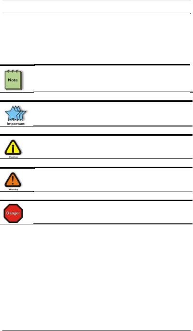
Five types of advisories are used throughout this manual to provide helpful information, or to alert you to the potential for hardware damage or personal injury. They are Note, Important, Caution, Warning, and Danger. The following is an example of each type of advisory.
NOTE
Used to amplify or explain a comment related to procedural steps or text.
IMPORTANT
Used to indicate an important piece of information or special “tip” to help you
CAUTION
Used to indicate and prevent the following procedure or step from causing damage to the equipment.
WARNING
Used to indicate and prevent the following step from causing injury.
DANGER or STOP
Used to indicate and prevent the following step from causing serious injury or significant data loss.
Disclaimer: We have attempted to identify most situations that may pose a danger, warning, or caution condition in this manual. However, Magma. does not claim to have covered all situations that might require the use of a Caution, Warning, or Danger indicator.
v
M A G M A
SafetyInstructions
Always use caution when servicing any electrical component. Before handling the Magma PCI-Express Expansion chassis, read the following instructions and safety guidelines to prevent damage to the product and to ensure your own personal safety. Refer to the “Advisories” section for advisory conventions used in this manual, including the distinction between Danger, Warning, Caution, Important, and Note.
♦Always use caution when handling/operating the computer. Only qualified, experienced, authorized electronics personnel should access the interior of the computer. The power supplies produce high voltages and energy hazards, which can cause bodily harm.
♦Use extreme caution when installing or removing components. Refer to the installation instructions in this manual for precautions and procedures. If you have any questions, please contact Magma Technical Support.
WARNING
High voltages are present inside the expansion chassis when the unit’s power cord is plugged into an electrical outlet. Disconnect the power cord from its source before removing the system cover.
Never modify or remove the radio frequency interference shielding from your workstation or expansion unit. To do so may cause your installation to produce emissions that could interfere with other electronic equipment in the area of your system.
WhenWorkingInsideaComputer
Before taking covers off a computer, perform the following steps:
1.Turn off the computer and any peripheral devices.
2.Disconnect the computer and peripherals from their power sources to prevent electric shock or system board damage.
3.Disconnect any telephone or telecommunications lines from the computer.
vi
M A G M A
In addition, take note of these safety guidelines when appropriate:
♦To help avoid possible damage to systems boards, wait five seconds after turning off the computer before removing a component, removing a system board, or disconnecting a peripheral device from the computer.
♦When you disconnect a cable, pull on its connector or on its strain-relief loop, not on the cable itself. Some cables have a connector with locking tabs. If you are disconnecting this type of cable, press in on the locking tabs before disconnecting the cable. As you pull connectors apart, keep them evenly aligned to avoid bending any connector pins. Also, before connecting a cable, make sure both connectors are correctly oriented and aligned.
CAUTION
Do not attempt to service the system yourself except as explained in this manual. Follow installation instructions closely.
ProtectingAgainstElectrostaticDischarge
Electrostatic Discharge (ESD) Warning
Electrostatic Discharge (ESD) is the enemy of semiconductor devices. You should always take precautions to eliminate any electrostatic charge from your body and clothing before touching any semiconductor device or card by using an electrostatic wrist strap and/or rubber mat.
Static electricity can harm system boards. Perform service at an ESD workstation and follow proper ESD procedures to reduce the risk of damage to components. Magma strongly encourages you to follow proper ESD procedures, which can include wrist straps and smocks, when servicing equipment.
You can also take the following steps to prevent damage from electrostatic discharge (ESD):
♦When unpacking a static-sensitive component from its shipping carton, do not remove the component’s anti-static packaging material until you are ready to install the component in a computer. Just before unwrapping the anti-static packaging, be sure you are at an ESD workstation or are grounded.
♦When transporting a sensitive component, first place it in an anti-static container or packaging.
vii

M A G M A
♦Handle all sensitive components at an ESD workstation. If possible, use anti-static floor pads and workbench pads.
♦Handle components and boards with care. Don’t touch the components or contacts on a board. Hold a board by its edges or by its metal mounting bracket.
Rack-MountInstructions
Elevated Operating Ambient - If installed in a closed or multi-unit rack assembly, the operating ambient temperature of the rack environment may be greater than room ambient. Therefore, consideration should be given to installing the equipment compatible with the maximum ambient temperature (Tma) Specified by the manufacturer.
Reduced Air Flow - Installation of the equipment in a rack should be such that the amount of air flow required for safe operation of the equipment is not compromised.
Mechanical Loading - Mounting of the equipment in the rack should be such that a hazardous condition is not achieved due to uneven mechanical loading.
Circuit Overloading - Consideration should be given to the connection of the equipment to the supply circuit and the effect that overloading of the circuits might have on overcurrent protection and supply writing. Appropriate consideration of equipment nameplate ratings should be used when addressing this concern.
Reliable Earthing - Reliable earthing of rack-mounted equipment should be maintained. Particular attention should be given to supply connections other than direct connections to the branch circuit (e.g. use of power strips).
viii
M A G M A
Chapter 1 Introduction
GeneralSpecifications
The Magma 7 Slot PCI Express® to PCI Express® Expansion System (Model EB7-x8) is a general-purpose bus expansion chassis for the Peripheral Component Interconnect Express (PCIe) local bus. The expansion chassis is fully compliant with the PCI Express Local Bus Specification. This system consists of a PCI Express host card, a 3– meter iPass cable, a rack-mount enclosure containing a 7 slot PCIe expansion backplane, a power supply, and cooling fans. The EB7-x8 can be easily transformed into a host computer with 8 slots when a Root Complex card is installed in place of the expansion interface card in the chassis.
|
|
|
|
|
|
Item |
|
Description |
|
|
|
Host Card: |
Low Profile PCI Express x8 (8 lane) |
|
|
|
Backplane: |
7 PCIe slots, 1 PCIe upstream or Root Complex |
|
|
|
|
slot |
|
|
|
Enclosure: |
4U Black Rack-mount (All Steel) |
|
|
|
Dimensions: |
19" W x 7" H x 17.7" D |
|
|
|
Weight: |
24 lb or 11.804 kg |
|
|
|
Standard Cable Length: |
3-meter iPass cable |
|
|
|
PCI Express Bus Specification |
Revision 1.1 |
|
|
|
PCI Local Bus Specification: |
Revision 2.3 |
|
|
|
PCI Bridge Architecture Spec: |
Revision 1.2 |
|
|
|
Interconnect Bandwidth: |
4000 MB/sec or 4 GB/sec or 40 Gbps |
|
|
|
Cooling: |
One 85.2 CFM fan |
|
|
|
|
One fan in power supply |
|
|
|
Power Supply: |
Model EB7-x8 includes an auto-switching 500W |
|
|
|
|
supply |
|
|
|
MTBF: |
53,000 hours |
|
|
|
Operating Environment: |
0º to 50º C Operating Temperature |
|
|
|
|
-20º to 60º C Storage Temperature |
|
|
|
|
5% to 85% Relative Humidity, Non-condensing |
|
|
|
Operating Systems: |
Windows XP/2000/Server 2003/Vista |
|
|
|
|
Mac OS X version 10.4.x + |
|
|
|
|
Red Hat Linux 9, Linux Kernel 2.6+ |
|
|
|
|
Solaris and Open Solaris 2008.05 |
|
|
|
Warranty: |
1 Year Return to Factory |
|
|
|
Available Options: |
|
7-meter cable (PN: SUBCBL7IP) |
|
|
|
|
Disk Drive Cage for up to seven 3.5” |
|
|
|
|
internal disk drives (PN: RDRIVECAGE) |
|
|
|
|
PCIe card hold down kit (PN: RCHD7) |
|
|
|
|
Rack-mount slide kit (PN: RSLIDES-XX) |
|
|
|
|
|
1
M A G M A
Pre-InstallationInformation
Before using the Magma expansion chassis you should perform the following steps:
•Inventory the shipping carton contents for all of the required parts
•Gather all of the necessary tools required for installation
•Read this manual
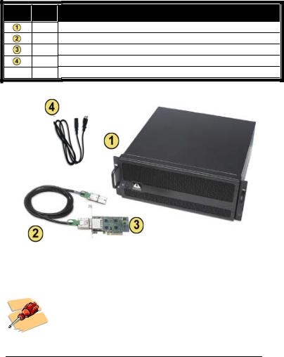
PartsList
The following parts are provided:
Item |
Qty |
|
1 |
1
1
1
1
Item
8 slot rack-mount chassis
3-meter shielded iPass™ x8 cable Half-height PCI Express host card U.S. Standard 115V power cord Quick Start Guide
ToolsRequiredforInstallation
In order to complete the installation of the Magma expansion system you will need a Phillips-head screwdriver.
2
M A G M A
Chapter 2 Hardware Installation
The following steps will guide you through the installation of your Magma expansion system.
Electrostatic Discharge (ESD) Warning
All PCI cards are susceptible to electrostatic discharge. When moving PCI cards, it is best to carry the cards in anti-static packaging. If you need to set a PCIe card down, be sure to place it inside or on top of an anti-static surface. For more information, see “Protecting Against Electrostatic Discharge” in the Preface.
WARNING
High voltages are present inside the expansion chassis when the unit’s power cord is plugged into an electrical outlet. Disconnect the power cord from its source before removing the enclosure cover. Turning the system power off at the power on/off switch does not remove power to components. High voltage is still present.
CAUTION
Before touching anything inside the enclosure, move to an ESD station and follow proper ESD procedures. Failure to do so may result in electrostatic discharge, damaging the computer or its components. For more information, see “Protecting Against Electrostatic Discharge” in the Preface.
STOP
If your Magma expansion chassis was not purchased directly from Magma, you must check to ensure that it doesn’t contain any preinstalled PCI cards.
Check the rear side of the chassis to see if any PCI cards are visible in the slots. If you see a PCI card, you should continue installation using instructions provided by your dealer. If no separate instructions are available, remove the cover by using instructions in Chapter 4 Install Cards and Drives. Then remove the card(s) as normal. If no PCI card is visible, then continue with the cable installation.
3
M A G M A
BeforeyouBegin
The 500W AC power supply is auto-switching. This means that it will automatically switch to match whatever source power you are using. Since all products ship with a US/Canadian Standard 125V power cord, you will need to use a locally available power cord for non-US Standard power sources.
InstallPCIExpressHostCard
Begin the installation of your PCI Express (PCIe) host card by first powering down your computer. Use the procedures for shutting down your operating system and shutting off power to your system provided in your owner’s manual or system documentation.
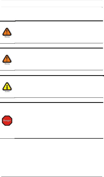
The PCIe host card is a “half-height” x8 PCIe card mounted to a “fullheight” bracket as shown below:
For low profile case applications, you may need to change the mounting bracket to the low profile bracket that shipped with your system. This is done by removing the screws that hold the card to the bracket. Be sure you are using proper ESD procedures when completing this action.
Once the host computer is off and all power cords disconnected, remove the cover and insert the PCI Express host card into a vacant x8 (or x16) PCIe slot by gently pushing the card until it is firmly seated. Then secure the card to the slot with a mounting screw.
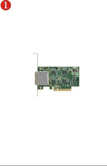
Notice that the PCI Express slots are located at a greater distance from the edge of the computer’s mother-board than are the standard PCI slots as illustrated in the following figure.
4
M A G M A
STOP
YOU MUST ONLY INSTALL THE PCIe HOST CARD INTO A PCI EXPRESS SLOT.
Only use cards WITH brackets. This will ensure that your PCIe host card can only be inserted into a PCIe slot. Although PCI Express cards without brackets may fit into conventional PCI slots, you run the risk of damaging the PCI Express host card if you insert it into a PCI slot. Please ensure that your host computer has PCI Express slots and install the host card only into a PCI Express slot.
For more information on using PCIe cards, please refer to your computer’s user manual or system documentation.
AttachPowerandExpansionCables
The 3-meter iPass cable included with your Magma expansion chassis features a x8 connector on each side.
Carefully position the expansion chassis so that the supplied expansion cable will conveniently reach from the host computer to the iPass connector on the back of the chassis. Then connect the x8 end of the
5
M A G M A
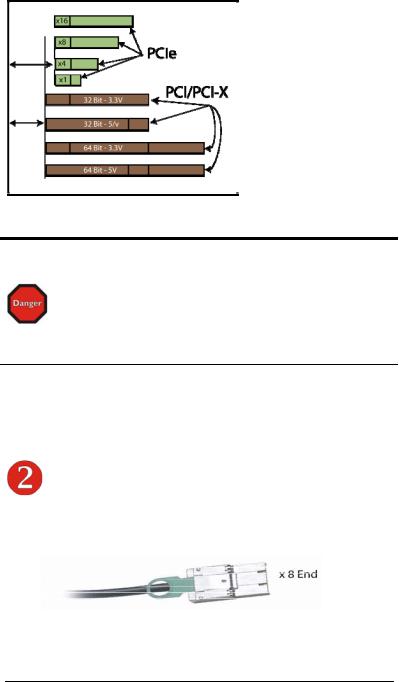
cable to the host card and the other end of the cable to the expansion interface card already installed in the chassis. Note: You may wish to verify the EIF is securely mounted in the chassis in the upstream slot.
Connect x8 end to |
Connect x8 end to |
the chassis along with the power cord. |
the host card. |
CAUTION
All cables attached to the expansion chassis must be securely fastened. When you hear a “click,” it is properly secured. If not securely connected, the connectors may cause intermittent or lost connections.
NOTE
If at all possible, plug all power cords from the expansion chassis and your host computer into a shared power strip, preferably one that has surge and noise suppression circuitry built into it.
Laptop Installation (optional)
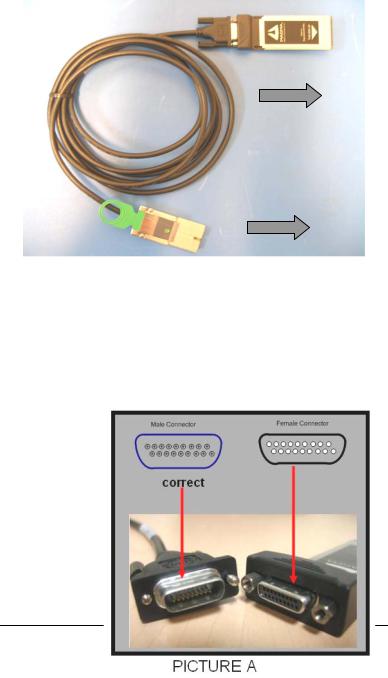
In addition to interfacing the EB7-x8 expansion system to a PC, you can now add additional PCI Express slots to your laptop by installing Magma’s ExpressCard host and connecting it to your chassis with a dedicated iPass-to-TDP cable featuring an iPass interface on one side and a TDP interface on the other.
6
M A G M A
Attach one end of the PCI Express cable to the Magma ExpressCard module and the other end to the connector on the back of the Magma chassis.
TDP side to Laptop
iPass side to EB7-x8 Chassis
Tighten the thumbscrews connecting the ExpressCard to the cable on one end and verify the other end is properly latched into the iPass connector of the chassis.
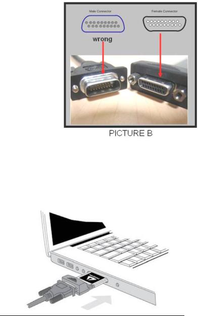
In spite of the standardized design of the TDP interface, it is not impossible to connect the male and female connectors upside-down. In order to avoid that, please note the proper and improper concavity orientation of the connectors as shown in the two cases below:
Picture A shows the correct orientation:
7
M A G M A
Picture B shows the Incorrect orientation:
Before inserting the Magma ExpressCard, power down your laptop computer. Use the procedures for shutting down and powering off your system provided in your owner’s manual or system documentation.
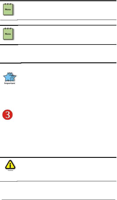
Insert the Magma ExpressCard module with the logo side up, into the ExpressCard slot on your computer. Gently push the card until it is firmly seated.
8
M A G M A
NOTE
The Magma ExpressCard module can only be used in a computer system that contains an ExpressCard slot. It will not function in CardBus or PCMCIA slots.
NOTE
If your laptop’s ExpressCard slot is “spring-loaded”, be sure that your ExpressCard is inserted correctly. It is very easy for this style slot to partially release a card if touched slightly.
For more information on using ExpressCard modules, please refer to your computer’s user manual or system documentation.
IMPORTANT
Due to an incompatibility issue between the chipsets used in the expansion system and those used by nVidia in its line of PCIe video cards, nVidia video cards will not function in the EB2 chassis if it is connected through the ExpressCard interface to the host PC. There is no issue interfacing with nVidia cards plugged into the EB2 chassis via the PCIe host card interface.
RechecktheInstallation
Check your installation before powering up the Magma expansion chassis for the first time. Although the power supply has an over voltage protection device built into it, it may not "trip" in time to fully protect a device that has been improperly connected, or whose power cable has been damaged.
CAUTION
This product is provided with a power supply that automatically adjusts to input voltages between 100 to 240 Vac. A U.S. and Canadian 125 V power supply cord is provided with this product. If using this product outside of the U.S. or Canada, please use locally available power supply cords
9
M A G M A
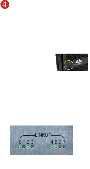
ApplyingPowerCorrectly
Starting Up:
It is recommended that you apply power to the Magma expansion chassis prior to powering up your computer. This will allow the PCIe bus hierarchy to be in a stable state when the host system issues its master power-on bus reset. This will also allow the software driver to recognize the PCI bus hierarchy and any attached devices.
The system’s On/Off switch is located on the front panel, as well as an LED indicator to indicate power status. Verify that the green power indicator is ON after pressing the
button.
Hardware Check
As your computer starts up, you will see LINKUP lights appear on the back o f the chassis near the iPass connector.
Green LINK LEDs
0 – Connection between host and chassis has been established
1 through 7 – PCI Express Cards have been found in respective slots
10
M A G M A
Windows Start Up
As your Windows computer starts up, you will see a small message box pop-up in the lower-right corner of the screen to alert you that Windows has found new hardware.
Now you are all set. The system does not require any Magma drivers in order to operate, unless you require Hot-Plug/Hot-Swap support (see Chapter 4 for more details).
You may now proceed to Chapter 3 Verify Installation.
MAC Start Up
Apple MAC OS computers will boot up without any visible indicators that the Expansion System is connected. Go to Chapter 3 Verify Installation.
Shutting Down:
STOP
DO NOT TURN OFF THE MAGMA EXPANSION CHASSIS UNTIL YOU HAVE SHUT DOWN YOUR COMPUTER COMPLETELY! It can cause a system lockup and loss of any unsaved data.
When shutting your system down, it is recommended that you first shut down the computer correctly, and then power down the Magma expansion chassis to avoid ‘computer lock-up’ and potential data loss.
RackInstallations
Installing the Magma EB7-x8 chassis into an equipment rack has never been easier. Simply attach one of Magma's optional Rack-mount slide kits (PN: RSLIDES-XX) to allow you to mount the chassis in a computer rack and then simply slide the chassis in and out whenever you need to do work on, or in, it. These sets come in various lengths to accommodate various racks. Contact Magma for more information, or to order a set. When ordering, replace the “XX” in the part number with your required kit size (18, 24, 26, or 28 inches).
11
M A G M A
12

M A G M A
CHAPTER 3 Verify Installation
Windows
To verify a successful installation on Windows, find the ‘My Computer’ icon and “right-click” on it. Then select ‘Manage’ from the pop-up menu. Next, click on ‘Device Manager’ in the leftmost Computer Management window. Finally, click on the View Menu and select View Devices by Connection.
Open ACPI (BIOS) Æ Open PCI BusÆ Click the ‘+’ sign several times until your reach a PCI Express Root Port with a PCI Standard PCI-to- PCI Bridge beneath it.
When installed correctly, you will see eight PCI Bridges (ports) below your system’s PCIe Root port: One uplink and 7 PCI-to-PCI bridges designated for 3rd Party PCIe cards installed in the chassis.
13
M A G M A
If everything is OK, then the Magma expansion system installation is complete.
If, however, the installation was unsuccessful, you may not see the PCI to PCI Bridge, or it will have a small yellow  in front of it.
Proceed to Chapter 6 for Troubleshooting installation problems.
MacOSX
When using Mac OS X no additional software or drivers are needed. The operating system should automatically recognize the Magma host card and expansion chassis.
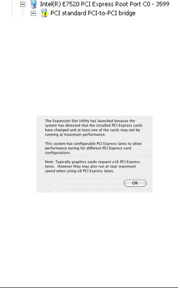
Expansion Slot Utility
The following screen may be displayed the first time you turn on your computer with the Magma EB7 installed.
Choose OK.
MacOS X is prompting you to choose a PCI Express profile that maximizes the performance of your attached devices. The Magma host card can communicate up to a bandwidth of x4 to and from the expansion chassis and devices. You should choose a profile that matches the configuration of all the cards installed in your Mac. Magma recommends that you install the system host card into a x4 slot in order to maximize throughput.
In this example, the Magma host card is installed in slot 4 and appears as “Intel PCI-to-PCI Bridge Card”.
14
 Loading...