

Page 1
EB3600-AB
MODEL
EB3600-AB
Us e r Manual
PCIe to PCIe Expansio n
Page 2

Magma
EB3600-AB |
2
Table of Contents
Preface.................................................................................................................................. 7
Advisories ......................................................................................................................................................................... 7
Safety Instructions ........................................................................................................................................................... 8
Chapter 1 Introduction .................................................................................................... 10
EB3600-AB Features ...................................................................................................................................................... 11
Technical Specification ............................................................................................................................................... 11
The core of ExpressBox 3600 ....................................................................................................................................... 12
Block Diagram .............................................................................................................................................................. 13
Configuration Model ................................................................................................................................................... 13
Parts List .......................................................................................................................................................................... 15
Components ................................................................................................................................................................. 16
Pre-Installation Information ......................................................................................................................................... 18
Tools Required for Installation ..................................................................................................................................... 18
Chapter 2 Hardware Installation ..................................................................................... 19
Installation-Procedures Overview.............................................................................................................................. 20
Open Enclosure ............................................................................................................................................................ 21
Install Expansion Interface Card ................................................................................................................................ 21
Install Host Interface Card .......................................................................................................................................... 24
Host Card installation in a Slot-Carrier ...................................................................................................................... 26
Connect Interface Cables ......................................................................................................................................... 28
Proper handling of cables ..................................................................................................................................... 28
How to insert the cable correctly ......................................................................................................................... 30
Connect cables to expansion unit ....................................................................................................................... 32
Secure all the cables with a retainer clamp. ..................................................................................................... 32
Connect cables to computer / server ................................................................................................................. 34
Proper Placement of Cables ................................................................................................................................. 35
Standard Cable vs. Daisy Chain Configurations................................................................................................ 35
Install PCIe card / GPU ................................................................................................................................................ 36
Installation of Singe-wide GPU .............................................................................................................................. 36
Installation of Double-wide GPU ........................................................................................................................... 36
Connect Auxiliary power ........................................................................................................................................ 38
PCIe card Memory Requirements ........................................................................................................................ 39
PCIe card Power Requirements ............................................................................................................................ 40
K-80 / GPU Installation ................................................................................................................................................. 41
Connect Auxiliary power adapter ....................................................................................................................... 43
Page 3

Magma
EB3600-AB |
3
Double-wide GPUs vs. Single-slot GPUs ................................................................................................................ 44
Connect Power Cord / Cable ................................................................................................................................... 45
Connect to Electrical Outlets ..................................................................................................................................... 45
Is it ok to connect four 1200W Power Supply modules to 120V? .................................................................... 45
Use two separate circuit lines ................................................................................................................................ 46
Do not use multiple electrical outlets on one circuit line ................................................................................. 46
Power ON the expansion unit .................................................................................................................................... 48
Power ON Computer ................................................................................................................................................... 49
Hardware Check .......................................................................................................................................................... 49
Host & Expansion Interface cards LEDs ................................................................................................................ 50
Front Panel Status LEDs ........................................................................................................................................... 51
Backplane LEDs ........................................................................................................................................................ 51
Completing Hardware Set up .............................................................................................. 52
Chapter 3 Software Installation ..................................................................................... 54
Install Software .............................................................................................................................................................. 54
Verify Installation .......................................................................................................................................................... 54
Windows .................................................................................................................................................................... 54
Linux............................................................................................................................................................................ 55
Check / Verify PCIe cards / GPU ............................................................................................................................... 61
Chapter 4 General & Technical Information .................................................................... 62
EB3600-AB ...................................................................................................................................................................... 62
Placement of GPUs on the expansion backplane ................................................................................................ 63
EB3600-AB with 10 “single-wide” GPUs................................................................................................................ 64
EB3600-AB with 9 “double-wide” GPUs ................................................................................................................ 64
Proper Placement of GPUs .................................................................................................................................... 65
Backplane PCIe slots and Ports assignment ............................................................................................................ 69
Backplane and LEDs .................................................................................................................................................... 70
Card Slot Link LEDs........................................................................................................................................................ 71
Interface Card and LEDs............................................................................................................................................. 72
Display Functions of Interface card LEDs ................................................................................................................. 73
Reset & Power Status LEDs .......................................................................................................................................... 74
Front Panel Status LEDs ................................................................................................................................................ 75
Fan LEDs ..................................................................................................................................................................... 75
Temperature Sensor Alarm LEDs........................................................................................................................... 75
Power Supply Indicator LEDs .................................................................................................................................. 76
Control Switches ........................................................................................................................................................... 76
SW1 and SW2 ............................................................................................................................................................ 77
Page 4

Magma
EB3600-AB |
4
SW3 ............................................................................................................................................................................. 77
SW4 ............................................................................................................................................................................. 77
Fan .................................................................................................................................................................................. 78
Fan Specs .................................................................................................................................................................. 78
Fan Replacement .................................................................................................................................................... 79
SNMP / Netburner ......................................................................................................................................................... 80
NetBurner Module ........................................................................................................................................................ 80
Replacing the NetBurner ........................................................................................................................................ 80
Netburner Installation .............................................................................................................................................. 82
Replacing the Interface Board ............................................................................................................................. 83
Netburner Interface Board Installation ................................................................................................................ 84
Power Supply unit ......................................................................................................................................................... 85
How to replace the power supply module ........................................................................................................ 85
How to Add Power Module to EB3600 ................................................................................................................. 87
Power Supply Specifications .................................................................................................................................. 87
Chapter 5 Management Console I/O Manager ................................................................. 91
SNMP Features .............................................................................................................................................................. 91
Web Access and SNMP Configuration..................................................................................................................... 91
Supported Internet Browser ................................................................................................................................... 91
To Access Express IO Manager / SNMP .................................................................................................................... 92
Connect Ethernet Cable ........................................................................................................................................ 92
Configure Network Setting ..................................................................................................................................... 92
How to configure your network setting in Windows OS .................................................................................... 92
How to configure your network setting in Linux / Ubuntu ................................................................................. 93
Launch Internet Browser ......................................................................................................................................... 94
Authentication Log-in ............................................................................................................................................. 94
Default Home Webpage ....................................................................................................................................... 95
Management Console / Web GUI ........................................................................................................................... 95
HOME ......................................................................................................................................................................... 95
ADMINISTRATOR ....................................................................................................................................................... 96
SNMP SETTINGS ......................................................................................................................................................... 96
ALARM SETTINGS....................................................................................................................................................... 97
NETWORK ................................................................................................................................................................... 97
REMOTE MANAGEMENT .......................................................................................................................................... 98
PCI-E INFO ............................................................................................................................................................... 101
Servicing the Side A or Side B .................................................................................................................................. 104
Turning OFF 3.3v when servicing the chassis ....................................................................................................... 104
Page 5

Magma
EB3600-AB |
5
Deactivating Server A/B (side A/B) .................................................................................................................... 105
Reactivating Server A/B (side A/B) ..................................................................................................................... 106
Fan Control ............................................................................................................................................................. 107
Fan Configuration .................................................................................................................................................. 108
Reset the chassis to default parameters ................................................................................................................ 109
Pressing the front power push button ................................................................................................................ 109
Flashing the Netburner .......................................................................................................................................... 109
Configure your SNMP Agent .................................................................................................................................... 110
Retrieving the MIB File ................................................................................................................................................ 110
Accessing the various SNMP functions ................................................................................................................... 110
Chapter 6 Functional / Benchmark Tests ...................................................................... 112
SNMP Verification Test ............................................................................................................................................... 112
Replaceable Fan Test ................................................................................................................................................ 113
Replaceable Power Supply Test .............................................................................................................................. 113
Express IO Manager “radio button” Test ................................................................................................................ 114
Express IO Manager Administration Test ................................................................................................................ 114
Chapter 7 Rack Slide Installation .................................................................................. 115
Installing the EB3600 Chassis in a Rack ................................................................................................................... 115
Rack Mounting ........................................................................................................................................................... 115
Rack Slides ................................................................................................................................................................... 115
Slide Rail Dimension Information .............................................................................................................................. 115
Specifications ......................................................................................................................................................... 116
Safety Instructions ....................................................................................................................................................... 117
Rack Stability .......................................................................................................................................................... 117
Tools and Supplies Needed ...................................................................................................................................... 118
Parts List ........................................................................................................................................................................ 118
Slide Rail Installation Instructions .............................................................................................................................. 120
Prepare Slide Rails for Assembly (STEP 1) ........................................................................................................... 120
Attach Rail to Chassis (STEP 2) ............................................................................................................................. 121
Assemble Slide Rails (STEP 3) ................................................................................................................................ 121
Add Screws to Rack Post (STEP 4) ....................................................................................................................... 123
Attach Slide Rail to Rack (STEP 5) ....................................................................................................................... 123
Attach Chassis to Slide Rail / Rack (STEP 6) ....................................................................................................... 125
Secure the Chassis to the Rack (STEP 7) ............................................................................................................ 126
Earth Leakage Current ......................................................................................................................................... 126
Grounding the EB3600-AB Expansion Chassis ....................................................................................................... 127
Regulatory Safety Requirements ........................................................................................................................ 127
Page 6

Magma
EB3600-AB |
6
Chapter 8 Updating Netburner / SNMP ......................................................................... 129
How to Update the Netburner on Linux ................................................................................................................. 129
Requirements.......................................................................................................................................................... 129
Procedures Overview............................................................................................................................................ 129
Download Files ...................................................................................................................................................... 129
Connect the Ethernet Cable ................................................................................................................................... 129
Launch the AutoUpdate.jar ..................................................................................................................................... 130
Check and verify the update .................................................................................................................................. 132
Chapter 9 Troubleshooting ............................................................................................ 133
Chapter 10 Chassis Maintenance ................................................................................... 135
General Chassis Cleaning ........................................................................................................................................ 135
Cleaning the Air Filter ................................................................................................................................................ 136
Chapter 11 Frequently Asked Questions (FAQ) ............................................................. 137
What are the differences between EB3600-10 and EB3600-AB? .................................................................. 139
Chapter 12 How to Get More Help ................................................................................. 140
Contacting Technical Support ................................................................................................................................ 140
Returning Merchandise to MAGMA ....................................................................................................................... 140
Online Support Resources ......................................................................................................................................... 141
Appendix A Compliance .................................................................................................................................... 142
Page 7
Magma
EB3600-AB | Preface
7
NOTE
Used to amplify or explain a comment related to procedural steps or text.
IMPORTANT
Used to indicate an important piece of information or special “tip” to help you
CAUTION
Used to indicate and prevent the following procedure or step from causing damage to the
equipment.
WARNING
Used to indicate and prevent the following step from causing injury.
DANGER or STOP
Used to indicate and prevent the following step from causing serious injury or significant
data loss
Preface
Advisories
Five types of advisories are used throughout this manual to provide helpful information, or to alert you to
the potential for hardware damage or personal injury.
Disclaimer: We have attempted to identify most situations that may pose a danger, warning, or caution
condition in this manual. However, Magma does not claim to have covered all situations that might require
the use of a Caution, Warning, or Danger indicator.
Page 8

Magma
EB3600-AB | Preface
8
WARNING
Never modify or remove the radio frequency interference shielding from your workstation or
expansion unit. To do so may cause your installation to produce emissions that could
interfere with other electronic equipment in the area of your system.
CAUTION
Do not attempt to service the system yourself except as explained in this manual. Follow
installation instructions closely.
Safety Instructions
Always use caution when servicing any electrical component. Before handling the Magma Expansion
chassis, read the following instructions and safety guidelines to prevent damage to the product and to
ensure your own personal safety. Refer to the “Advisories” section for advisory conventions used in this
manual, including the distinction between Danger, Warning, Caution, Important, and Note.
Always use caution when handling/operating the computer. Only qualified, experienced,
authorized electronics personnel should access the interior of the computer and expansion
chassis.
When Working Inside a Computer
1. Before taking covers off a computer, perform the following steps:
2. Turn off the computer and any peripheral devices.
3. Disconnect the computer and peripheral power cords from their AC outlets or inlets in order to
prevent electric shock or system board damage.
In addition, take note of these safety guidelines when appropriate:
To help avoid possible damage to systems boards, wait five seconds after turning off the computer
before removing a component, removing a system board, or disconnecting a peripheral device
from the computer.
When you disconnect a cable, pull on its connector or on its strain-relief loop, not on the cable
itself. Some cables have a connector with locking tabs. If you are disconnecting this type of cable,
press in on the locking tabs before disconnecting the cable. As you pull connectors apart, keep
them evenly aligned to avoid bending any connector pins. Also, before connecting a cable,
make sure both connectors are correctly oriented and aligned.
Page 9

Magma
EB3600-AB | Preface
9
Electrostatic Discharge (ESD) Warning
Electrostatic Discharge (ESD) is the enemy of semiconductor devices. You should always
take precautions to eliminate any electrostatic charge from your body and clothing before
touching any semiconductor device or card by using an electrostatic wrist strap and/or
rubber mat.
Protecting Against Electrostatic Discharge
Static electricity can harm system boards. Perform service at an ESD workstation and follow proper ESD
procedures to reduce the risk of damage to components. Magma strongly encourages you to follow
proper ESD procedures, which can include wrist straps and smocks, when servicing equipment.
You can also take the following steps to prevent damage from electrostatic discharge (ESD):
When unpacking a static-sensitive component from its shipping carton, do not remove the
component’s anti-static packaging material until you are ready to install the component in a
computer. Just before unwrapping the anti-static packaging, be sure you are at an ESD
workstation or are grounded.
When transporting a sensitive component, first place it in an anti-static container or packaging.
Handle all sensitive components at an ESD workstation. If possible, use anti-static floor pads and
workbench pads.
Handle components and boards with care. Do not touch the components or contacts on a board.
Hold a board by its edges or by its metal mounting bracket.
Page 10

Magma
EB3600-AB | Chapter 1 Introduction
10
Product Name
Description
EB3600-AB
Ten peripheral slots and two host link slots (All Gen 3 x16)
Chapter 1 Introduction
EB3600-AB
Magma ExpressBox 3600-AB is a 10-Slot PCI Express® Expansion System optimized for High Performance
Computing (HPC) applications. The expansion system consists of a PCIe® host interface card, High
Speed/HD IO cables, a 4U rack-mount chassis containing a 10 Slot backplane and an expansion interface
card, a replaceable power supply, and high CFM replaceable cooling fans.
Provides the optimum features for supporting world class High Performance Computing (HPC)
applications that demand ‘mission critical’ features such as N+1 redundant power and cooling
and high speed PCIe Gen 3 x16 connectivity.
It comes with a network management interface, including a web based GUI and SNMP interface
for monitoring the health of the chassis. The design is optimized for HPC applications built with
leading edge GPUs such as NVIDIA K-Series/GRID, AMD and coprocessors.
It is ideal for HPC applications such as oil and gas exploration, financial modeling, medical
imaging, genome sequencing, and simulation – any application requiring big data set analysis and
processing.
With the capacity for up to 9 state-of-the-art GPUs (e.g. NVIDIA K40), support for up to 12.9 Tflops (double
precision) or 38.6 Tflops (single precision) can be obtained within one ExpressBox 3600. For Big Data
applications, this level of performance is a game changer in the field of data mining and other
applications that could not be addressed just a short number of years ago.
Up to 38.6 Teraflops (single precision) or 12.9 Teraflops (double precision) of performance possible
(data representative of nine NVIDIA K40s).
Provides expansion for up to ten PCIe Gen 3 x16 peripherals including up to nine double width GPU
modules.
Passive host interface: no PCIe switch on host link cards, providing lowest latency possible.
Full 300W per slot power support (with included PCI AUX power).
Redundant N+1 air cooling for up to nine GPU modules.
19” Rack-mountable metal, 4U chassis 16.8” Wide x 7” High (4U) x 22.125” Deep.
Configurable and replaceable N+1 capable power supply solutions of 1200W, 2400W, 3600W or
4800W
Page 11

Magma
EB3600-AB | Chapter 1 Introduction
11
EB3600-AB
2 PSUs per segment. 2400W at 120v or 3000W at 240V full power OR 1200W/1500W
N+1 redundant for segment A and segment B independently.
HARDWARE
Backplane
EB3600-AB: ten peripheral slots and two host link slots (All Gen 3 x16)
Interconnect Bandwidth
PCIe Gen 3 x16: 128 Gbits/sec to all peripherals and host link
ENCLOSURE
Material
Steel Chassis
Dimension
16.8” Wide by 7” High (4U) by 22.125” Deep
HOST CONNECTION
Host side: Any PCIe based host-equipped
computer (preferably Gen 3 x16)
Expansion side: All host links are Gen 3 x16 capable and will train down to Gen 2 or 1
as needed. The host connection that the cards will automatically down train to the
link width to the one that is maximum for a given slot electrically
Switchless host link adapter design for
minimal host/expansion latency
POWER SUPPLY
1200W PSU
Additional replaceable 1200W AC power PSU. Can be added to base models above.
Up to four total (4800W total)
ENVIRONMENT
Ambient Temperature
0º to 50º C
Storage Temperature
-55º to 125º C
Relative Humidity
0% to 90% non-condensing
REGULATORY COMPLIANCE
FCC Class A Verified
RoHS Compliant
CE Certified
SUPPORTED OPERATING SYSTEMS
Windows
Mac OS
Linux
Solaris
EB3600-AB Features
Easy “Plug and Play” installation
PCI Express Gen 3 x16 or x8 interconnection
All slots support full-length cards
Status LEDs on backplane indicate active link, speed (Gen 3 or Gen 2, or Gen 1)
Automatic power-up control by computer
Four replaceable cooling fans
Multiple power supply options with auxiliary power connectors
Industrial 4U rack-mount enclosure
Chassis provides superior EMI control, vibration, shock and moisture resistance
Magma Express I/O Manager
Constant critical component monitoring
Front panel status LED display
SNMP and Express I/O Manager with built-in web graphical user interface
Serviceable Server A and / or B
Technical Specification
Page 12

Magma
EB3600-AB | Chapter 1 Introduction
12
The core of ExpressBox 3600
PCI Express Gen 3 x16 Backplane
6 slots per backplane - up to 2 backplanes in Express Box 3600
Support for 4 (or 5) double wide GPUs
Up to two backplanes fit in 1 19” rack
Mechanical cooling considerations for GPU requirements (300W Modules)
PCIe Gen 3 x16 passive (invisible to system) links between all nodes including Host (Slot 0 or Slot 5)
Page 13

Magma
EB3600-AB | Chapter 1 Introduction
13
Block Diagram
Configuration Models
Model 1: Configuration model for EB3600-AB, attached to one host server. Two link interface cards
plugged into the server. Two link cables per interface card.
Page 14

Magma
EB3600-AB | Chapter 1 Introduction
14
Model 2: Attached to two host servers. One Interface card per server. Two link cables per interface card.
Page 15

Magma
EB3600-AB | Chapter 1 Introduction
15
#
Item Description
EB3600-AB
Quantity 1 Host Interface card
2
2
1-meter High Speed / HD IO cable
4
3
U.S. Standard 115V Power Cord
1 per supplied PSU 4 Expansion Interface card
2
5
Quick Start Guide
1
6
1200W Power Supply Modules (installed)
Requires 4 7 Replaceable Fan (installed)
4
For EB3600-AB, it ships with 4 power supply bricks / modules. To support 4 GPUs it requires 2
power supply bricks.
Parts List
Page 16

Magma
EB3600-AB | Chapter 1 Introduction
16
Components
Once you have completed your inventory, your next step is to be familiarized with components of the
EB3600-AB expansion unit.
The expansion unit is composed of the following integral components
1. Expansion Backplane
a. 10 PCIe x16 slot (electronic and mechanical)
b. Two designated Link-Up SLOTs for Interface card
c. Slot LEDs, Link and Activity LEDs (30 LEDs)
d. Thermistor control switch
2. Interface card
a. Expansion and Host mode DIP switch
b. Speed Toggle switches
c. Two Cable ports: one for x8 and the other is x16
3. Power Supply, redundant and field replaceable
a. Power cord socket
b. LED status indicator
c. Locking Thumb screw
d. 18 (6+2 pin) PCIe connectors
e. Replaceable
4. Replaceable Fans
a. 185 CFM
b. Locking Thumb screw
c. Air Flow: from outside going inside
5. SNMP Interface module
a. Netburner
b. RJ45 port
Front panel: you will find the following
1. Push button On/Off switch
2. Front Panel Status LED
3. Front Grill cover (Dust-Foam filter behind the cover)
Rear Panel, you will see the following
1. PCI Express card slot opening
2. Interface card cable ports (x8 and x16)
3. Power Supply
4. RJ-45 Ethernet port
5. Top cover Thumb Screws
6. Power Rating
7. Serial number
Page 17

Magma
EB3600-AB | Chapter 1 Introduction
17
Page 18

Magma
EB3600-AB |
18
Pre-Installation Information
Before using the Magma Expansion chassis, you should perform the following steps:
• Inventory the shipping carton contents for all of the required parts
• Gather all of the necessary tools required for installation
• Read this manual
Tools Required for Installation
To complete the installation of the Magma product you will need a Phillips-head screwdriver and ESD wrist
strap to prevent electrostatic discharge.
Page 19
Magma
EB3600-AB | Chapter 2 Hardware Installation
19
CAUTION
Hardware installation shall be performed only by qualified service personnel.
Electrostatic Discharge (ESD) Warning
All add-in cards are susceptible to electrostatic discharge. Use anti-static packaging when
carrying or transporting cards. If you need to set a circuit card down, be sure to place it
inside or on top of an anti-static surface. For more information, see “Protecting Against
Electrostatic Discharge” in the Preface.
WARNING
High voltages are present inside the expansion chassis when the unit’s power cord is
plugged into an electrical outlet. Disconnect the power cord from the AC outlet before
removing the enclosure cover. Turning the system power off at the power on/off switch
does not remove power to components. High voltage is still present.
CAUTION
Before touching anything inside the enclosure, move to an ESD station and follow proper
ESD procedures. Failure to do so may result in electrostatic discharge, damaging the
computer or its components. For more information, see “Protecting Against Electrostatic
Discharge” in the Preface.
Chapter 2 Hardware Installation
The following steps will guide you through the installation of your Magma Expansion System.
Page 20

Magma
EB3600-AB | Chapter 2 Hardware Installation
20
NOTE
It is highly recommended to install any 3rd party PCI-E cards / High Power PCIe cards after
you have verified and tested the Magma expansion is functional and no hardware failures.
Installation-Procedures Overview
Below is the concise version on how to set up the EB3600-AB.
1. Open Enclosure
2. Install Expansion Interface card(s) (If not installed).
3. Install Host Interface card(s) into host computer
4. Install Cable (Connect A to A and B to B on interface cards between the host and expansion
chassis)
5. Install PCIe cards (see notes below)
6. Attach Power Cords
7. Connect to Electrical Outlet – verify adequate circuit capacity for wattage needed (this may
require multiple circuits)
8. Power- ON (power-up) EB3600-AB
9. Power-ON (power-up) Computer
10. Hardware Check
11. Verify Installation (via Operating System)
When installing 3rd Party PCIe card, start with one card first just to see if there are any software and
hardware issues or incompatibility problems that may occur. This way you can troubleshoot the problem
more easily and efficiently. If everything works well and there are no configuration issues, you can proceed
with the installation of the remaining 3rd party PCIe cards.
Always refer to or read “3rd party manufacturer installation guide” for further instructions.
Page 21

Magma
EB3600-AB | Chapter 2 Hardware Installation
21
Open Enclosure
Loosen the thumbscrews that retain the top cover of the chassis and slide the lid towards you as shown
below:
Install Expansion Interface Card
By default, the 2 Expansion interface cards are already installed in their designated slot. This model
EB3600-AB comes with 4 Interface cards, 2 for expansion and 2 for host server. There are two separate PCB
backplanes side-by-side in the chassis. Each PCB backplane requires 1 Expansion Interface card linked to
the host computer / server. The Interface card is Gen3 x16; it has two cable ports for linking either by x8 or
x16 connection. Should you need to install the card, follow the steps below.
Page 22
Magma
EB3600-AB | Chapter 2 Hardware Installation
22
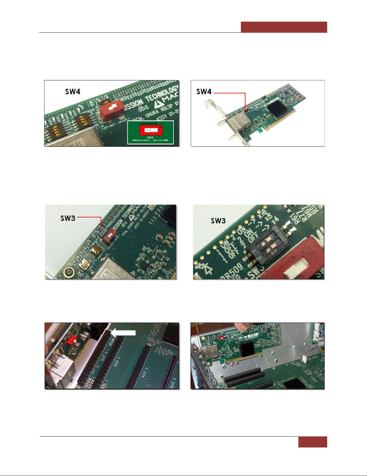
Make sure to check the dipswitch (SW4) is set to proper configuration. The toggle switch should be
“ON=EXP” position as shown from the picture below. Apply the same configuration with the second
Expansion Interface card. By default the Expansion Interface card is set to “ON=EXP” and configured as
x16.
Next, check the SW3. This is another dipswitch that you need to check prior to installing the interface card.
The SW3 has two toggle switches and are set to x16 by default, see pictures below. User should not alter or
change the settings of SW3. If you encounter problems, for troubleshooting purposes only check SW3;
verify the dipswitches are set to x16.
When done verifying the SW4 and SW3 settings are correct, you can now plug in the primary Expansion
Interface card in the designated PCIe “SLOT 0-UPLINK, see pictures below.
Page 23

Magma
EB3600-AB | Chapter 2 Hardware Installation
23
NOTE
The SW3 has two toggle switches and are set to x16 by default, see pictures below.
For the second Expansion Interface card, use the PCIe “SLOT 5-UPLINK”. Secure the edge connector
bracket with a retaining screw.
NOTE: The “Expansion” interface is the same card as the “Host” interface card. The only difference is the
setting on the SW4 switch. When SW4 is set to “ON=EXP”, the card becomes “Expansion interface card”,
and plugs into an expansion slot in the chassis. When it is set to “OFF-HOST, and plugs into a computer slot,
it is a “Host interface card”. See pictures below for the SW4 settings.
The Interface card has a mini built-in configurable toggle switch that can be set to x4, x8 and x16. The
expansion interface card default setting is x16. If the SW3 is not set correctly, your expansion system will not
link up properly to the host server / computer.
Page 24

Magma
EB3600-AB | Chapter 2 Hardware Installation
24
Install Host Interface Card
Begin installation by powering down your host computer. Use the procedures for shutting down your
operating system and shutting off power to your system provided in your owner’s manual or system
documentation. The host interface card is mounted to a “full-height” bracket as shown below. For low
profile case applications, you may need to change the mounting bracket to the low profile bracket that
shipped with your system. Remove the screws that hold the card to the bracket. Be sure you are using
proper ESD procedures when completing this action.
When the host computer is off and all power cords are disconnected from the AC outlet, remove the cover
and prepare your host card for insertion into a PCIe slot.
When the Magma interface card is used as “Host” interface i.e. installed in the host computer, the RED
switch should remain OFF. Check the Dipswitch and make sure it is set to OFF=HOST.
This version of Host Interface card has a mini built-in configurable toggle switch (SW3) that can be set to x4,
x8 and x16. There is no need to make changes to the link width; the card will automatically negotiate the
link width if different from x16.
Page 25
Magma
EB3600-AB | Chapter 2 Hardware Installation
25
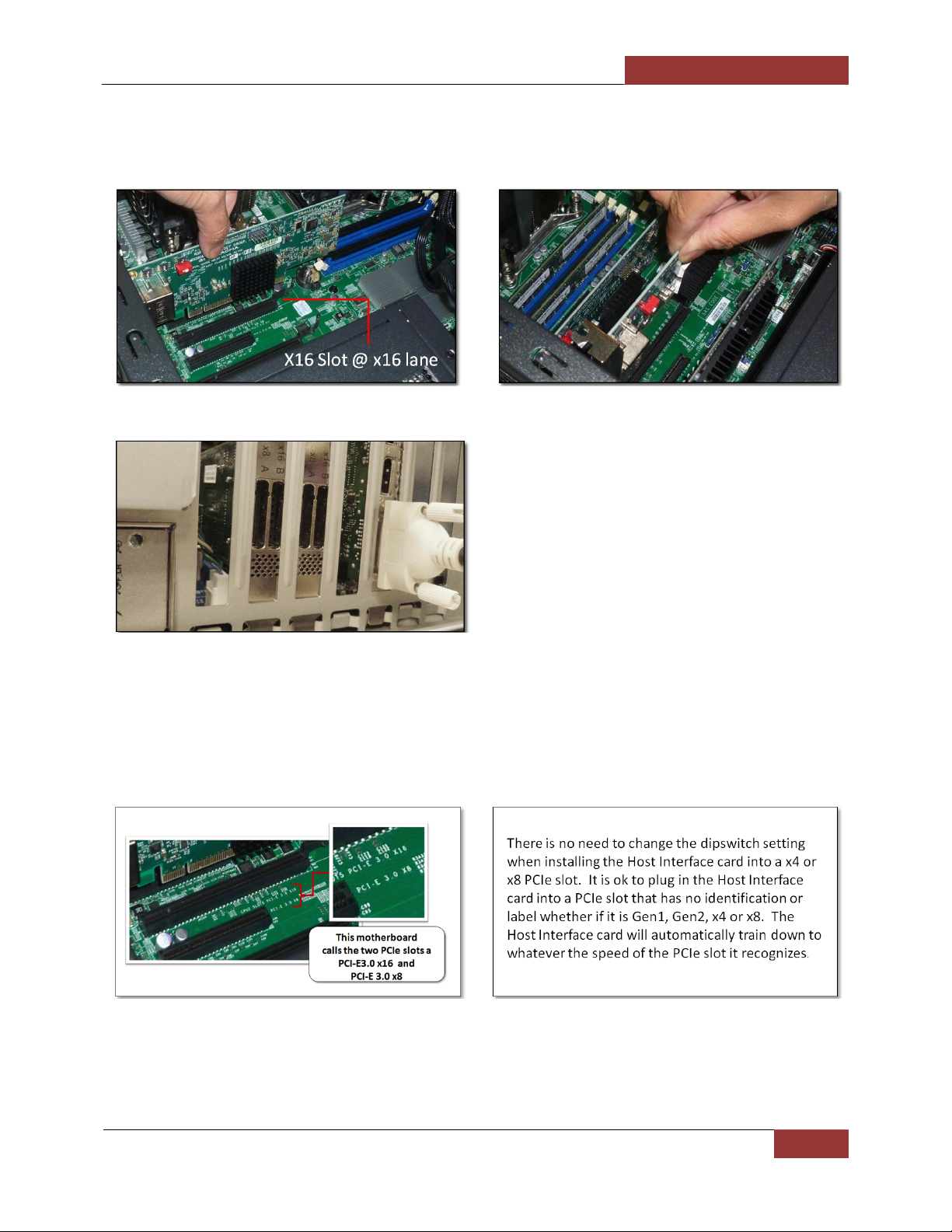
Install the two Host interface cards into the host computer. Use available x16 PCIe slot for both Host
Interface cards. Plug in the host card to the PCIe slot closest to the PCIe CPU, this allows the BIOS to
enumerate the host card first. Secure it with a retaining screw.
There are 2 host cards available for this chassis. It is important to know how many lanes the host computer
slot can support. The host card does not need to be configured for the same number of lanes as the host
computer slot. The host card will train down to whatever the PCIe slot speed is that it recognizes. For
example, if the host interface card is installed in a x8 lane card slot; leave the host card setting as is. The
host computer dictates what link width and speed the expansion system will operate in.
Page 26

Magma
EB3600-AB | Chapter 2 Hardware Installation
26
Host Card installation in a Slot-Carrier
If you are using a server- type computer that has a slot-carrier please follow the instructions below. You
have to remove the slot-carrier housing from the host server in order to install the interface card.
Install Interface card
Page 27

Magma
EB3600-AB | Chapter 2 Hardware Installation
27
Secure Interface card
Put the slot-carrier housing back into the host server
Install the second Host interface card in the second slot carrier
Page 28

Magma
EB3600-AB | Chapter 2 Hardware Installation
28
Connect Interface Cables
The EB3600-AB expansion unit uses High Speed / High Density IO cables (HDLSP- High Density Low Skew Pair
cable) that deliver superior performance. It is an ideal solution for super-computing and data storage
applications including servers, blade servers, and server clusters, providing vast modularity between systems
and subsystem. The cable is available in 1-meter length.
Connect Cables to Expansion Interface cards and connect the other end to Host Interface cards. Be
attentive which port to plug in the cable to. The Interface card has two cable ports labeled with x8 A and
x16 B. Connecting the cable to the wrong port can cause the system malfunction. Always remember to
plug in cable to “A to A” and “B to B” ports. Proper way of connecting the High Speed / HD cable to
Interface card is shown from the picture below.
Proper handling of cables
Prior to connecting the x16 cable make sure to do the following:
1. Ensure no power is applied to any of the four PS modules on the expansion system.
2. Make sure to unfasten bracket screw, remove and reseat the target cards as shipping may have
misaligned the target cards. After ensuring the cards are seated correctly reinsert the I/O bracket
screw.
a. Make sure when transporting this expansion systems that no cards travel inside system.
When expansion reaches its destination always reseat and fasten any cards that may
have been left inside before applying power.
3. Avoid hitting any metal part of the interface card as this can damage the pins of the cable.
a. Insert one cable at a time, by controlling both ends of the cable.
4. Avoid forcing the cable in, make sure to align it to the port correctly and insert properly
a. When inserting the cables ensure the alignment key is on the top end of the host and
target cards.
b. If too much resistance is felt, inspect the cable end for a loose clip or damaged pins. If
damaged do not use, replace cable immediately.
5. Ensure that both cables are seated; they should both be aligned when inserted properly. Use of
the cable clamps (provided) is encouraged to avoid accidental disconnections.
Page 29

Magma
EB3600-AB | Chapter 2 Hardware Installation
29
The pictures below are an example of two misaligned cables.
Avoid the following:
1. Do not unplug the cable while the unit is ON
2. Do not wiggle the cable while the unit is ON
3. Do not plug in the cable while unit is ON
4. Do not use a damaged cable or cable with broken pins. Inspect the end connector of the cable
for damaged pins prior to connecting to the interface card.
The pictures below are example of a cable with a damaged /broken pin.
When the cable is detached or not connected, please use the plastic cap to cover the end connector of
the cable. This will protect the connector and prevent the pins from being damaged.
Page 30
Magma
EB3600-AB | Chapter 2 Hardware Installation
30
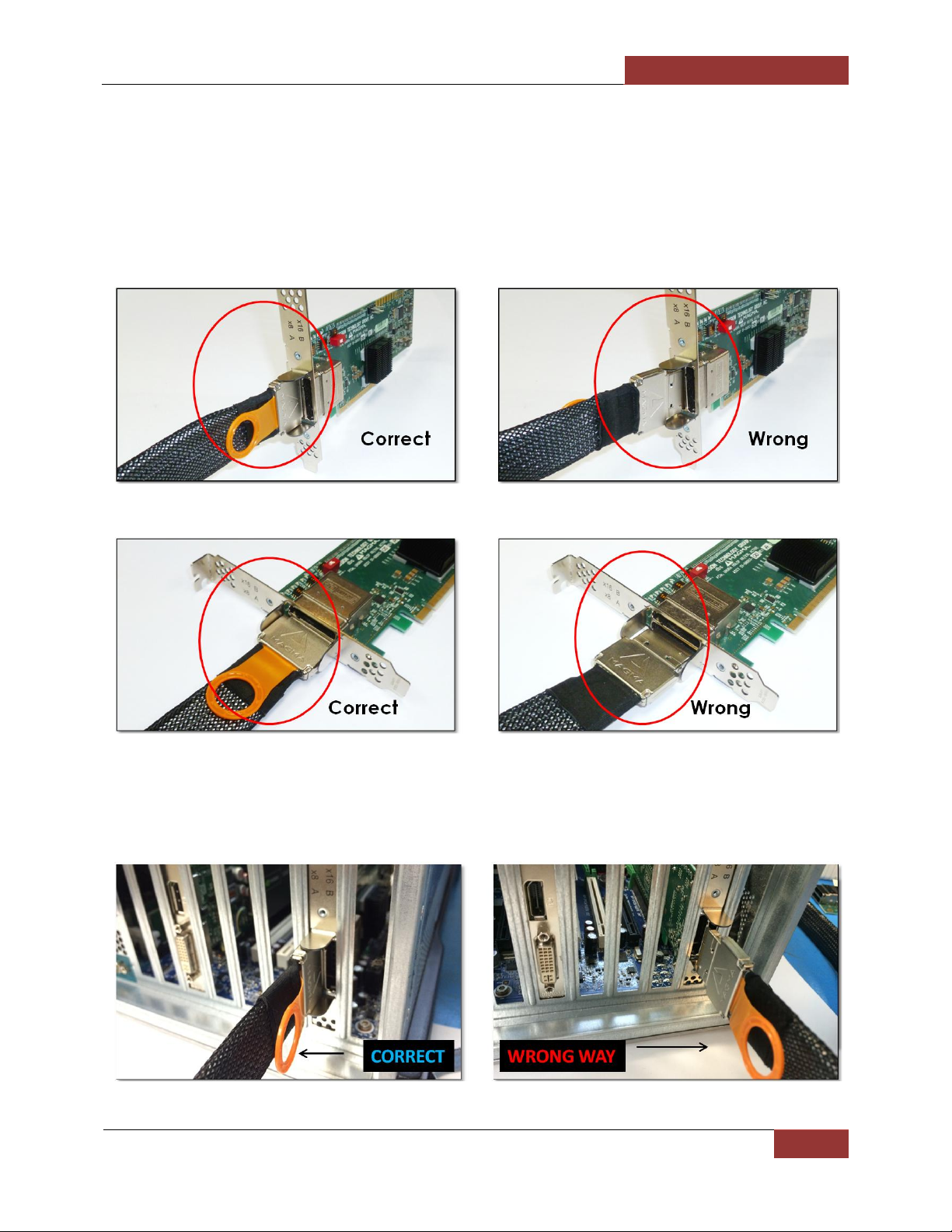
How to insert the cable correctly
Proper orientation of cable must be followed when connecting it to the interface card port. The illustration
below describes the wrong and correct cable orientation. The direction of the interface card installed in
the PCIe slot dictates the proper positioning of the cable. If you insert the cable in a wrong orientation
and try to force it in, this will damage the end-connector. Once the end-connector of the cable is
damaged, the entire cable must be replaced. A broken or damaged cable connector can lead to
instability or link failure between expansion unit and host system.
The Interface card is installed vertically as illustrated below. The image on the left side is the correct
orientation of the cable, the orange plastic tab is facing toward the right side. The image on the right is
the incorrect cable orientation.
Page 31

Magma
EB3600-AB | Chapter 2 Hardware Installation
31
The pictures below, the Interface card is installed horizontally to the PCIe slot connector located on the
right side of the server case / enclosure. The image on the left is the correct cable orientation. The image
on the right is the incorrect cable orientation.
The pictures below, the Interface card is installed horizontally to the PCIe slot connector located in the left
side of the server case / enclosure. The interface card label is upside down. This means you have to flip the
cable prior to inserting to the cable port. The Image on the left is the correct position, the image on the
right is the incorrect one.
Page 32

Magma
EB3600-AB | Chapter 2 Hardware Installation
32
Connect cables to expansion unit
FOR EB3600-AB, you need four cables. Plug in cables to Magma EB3600-AB unit
Connect the first set of cable to the expansion interface card located on the left side of the expansion unit.
Connect the 1st cable to port X8 A
Connect the 2nd cable to port X6 B
Connect the second set of cable to the expansion card located on the far right side of the expansion unit.
Connect the 3rd cable to port X8 A
Connect the 4th cable to port X16 B
Secure all the cables with a retainer clamp.
Page 33

Magma
EB3600-AB | Chapter 2 Hardware Installation
33
See pictures below for proper installation of cable retainer (cable clamp)
Page 34

Magma
EB3600-AB | Chapter 2 Hardware Installation
34
Connect cables to computer / server
Connect the other end of the 1st cable to port X8 A of the host interface card.
Take the other end of the 2nd cable and connect that to port X16 B of the host interface card.
Do the same thing to the remaining 3rd and 4th cables. Make sure to connect the end of the cables to the
appropriate ports.
Secure all the cables with a retainer clamp.
This is an overview of what it looks like after connecting the cables to Magma EB3600-AB and Host Server /
Computer. See picture below.
Page 35

Magma
EB3600-AB | Chapter 2 Hardware Installation
35
Proper Placement of Cables
Correct & wrong ways to connect the cables to interface cards (host and expansion) are illustrated below.
It is important to know what correct port to use to plug in the cable. Plugging in the cable to the wrong
port will render the expansion unit inoperable.
Standard Cable vs. Daisy Chain Configurations
Page 36

Magma
EB3600-AB | Chapter 2 Hardware Installation
36
Install PCIe card / GPU
Installation of a single-wide PCIe card or single-wide GPU is a straightforward process. However, when
installing multiple double-wide GPUs it requires strict methods that must be followed. See details below for
instructions on installation of double-wide GPU.
Installation of Singe-wide GPU
1. Be sure to turn off your expansion unit and unplug it from the wall before you begin
2. Remove filler bracket for the expansion slot you wish to use in the chassis.
3. Align the new GPU card with the empty socket
4. Gently push down evenly on both ends of the card until it is fully seated in the socket. Ensure that
the card’s rear-panel tab sits flat against the PCIe rear-panel opening
5. Next, use a screw to secure the graphic card's metal retention bracket to your expansion unit
case.
Installation of Double-wide GPU
A double-wide GPU cover two slots. When installing multiple or 8 to 9 double-wide GPUs you must begin
placing the GPU in the far right of the backplane (looking from the rear). This will allow you to see the slot
location and align the GPU connector easily on top of the slot. Start installing the GPU one at a time from
right to left.
Page 37

Magma
EB3600-AB | Chapter 2 Hardware Installation
37
There are minute components that are mounted above the gold-finger connector of the
K80 and some GPUs, see pictures below. When these components are broken off or
become detached from the board, your K80 or GPU will be inoperable.
Be very careful and cautious when plugging in a GPU into a PCIe slot. If the card is not correctly aligned
to the slot while plugging in, it can hit and damage one of these components. See picture below as an
example of a detached / damaged components.
To avoid damaging these components, install the GPU in the far right of the backplane (looking from the
rear) and align the GPU connector on top of the PCIe slot and slowly push it down until firmly seated.
Make sure that all cards are fully seated in their connectors. When correctly seated, there will be a firm
resistance when you pull up gently the card. To keep the cards in place, secure them in the enclosure with
their retaining screws.
Page 38

Magma
EB3600-AB | Chapter 2 Hardware Installation
38
Connect Auxiliary power
A high power PCIe card such as a GPU requires additional power.
Aside from the power being supplied by the PCI-Express slot, which is 75 watts, there is not enough to meet
the power requirement for a high-end GPU with power consumption of over 125 Watts. A direct
connection to the power supply is needed to obtain additional power.
This can be done by using the 6+ 2 pin PCIe cable connector from the expansion unit. Top-of-the-line
graphics processing units or GPUs have a built-in AUX power port in which you may attach the PCIe cable
connector.
The picture below shows how the 6+2 pin connector is attached to the GPU.
Page 39

Magma
EB3600-AB | Chapter 2 Hardware Installation
39
PCIe card Memory Requirements
Always check the general system and hardware requirements as well as optimal CPU and GPU settings
when using High Power GPUs. For example, you are using five XYZ brand Doublewide GPUs and each GPU
requires 16GB of PCI Memory Address space. In order for these 5 XYZ GPUs to operate properly, a total of
80G of host system memory is needed during system boot. The system BIOS, during POST, will typically
check for equivalent host system memory to be able to support PCI address space. The host computer
should match or exceed the memory requirements of the total GPU PCI address space to achieve better
performance and avoid problems that may cause the entire system to malfunction. Random crashes and
other unexpected errors can occur if GPU memory requirements are not met or the system may not
boot at all if the BIOS checks for and sees a mismatch on PCI address space and host system memory
capacity. Check with GPU manufacturers for details on memory and systems requirements.
Memory-Mapped I/O Greater than 4 GB:
All supported GPU cards require enablement of the BIOS setting that allows greater than 4 GB of memorymapped I/O (MMIO).
Standalone Server: If the server is used in standalone mode, this BIOS setting is enabled by default:
Advanced > PCI Configuration > Memory Mapped I/O Above 4 GB [Enabled]
Page 40

Magma
EB3600-AB | Chapter 2 Hardware Installation
40
Number of Pins
Watt
6 pin connector
provides 75 Watts
8 pin connector
provides 150 Watts
PCIe card Power Requirements
Power consumption is crucial for all CPUs and GPUs and other High-End Power Hungry PCIe cards. GPUs
consume a great deal of power. As the processing power of graphic cards has increased, so has their
demand for electrical power. Due to the limitations of the card slot PCI-Express connector that only
supplies 75 Watts of power, present GPU cards with power consumption of over 75 Watts now includes a
combination of six-pin (75 W) and or eight-pin (150 W) connectors. If these are not available, you can use
the internal AUX power connectors in the expansion unit (see picture below).
There are 18 (6+2 pin) PCIe AUX power connectors available in the expansion unit for providing extra
power to PCIe cards / GPUs.
For example, when using a GPU card that has a maximum power consumption of 225W you would need to use two
six-pin power connectors.
Magma EB3600-AB uses a 6+2 pin PCIe power connectors. It can be used as 6-pin or 8-pin connector depending on
what the PCI-E card or GPU required.
Page 41

Magma
EB3600-AB | Chapter 2 Hardware Installation
41
K-80 / GPU Installation
There is an order or proper method of installing double-wide GPUs in the expansion unit. The process of
installing multiple doublewide GPUs across the two backplane are illustrated below.
When installing multiple or 8 to 9 GPUs you must begin placing the GPU in the far right of the backplane
(looking from the rear). Allowing you to see the slot location and align the GPU connector easily on top of
the slot. Start installing the GPU one at a time from right to left.
Page 42

Magma
EB3600-AB | Chapter 2 Hardware Installation
42
Page 43

Magma
EB3600-AB | Chapter 2 Hardware Installation
43
When all the GPUs are plugged in, next is to secure it with screws.
Connect Auxiliary power adapter
1. Connect breakout auxiliary power adapter to K80 power connector.
2. Connect the EB3600-AB auxiliary power connector to the K80 breakout auxiliary power adapter.
The K80 comes with a breakout auxiliary power adapter.
Connect the breakout auxiliary power adapter to K80 power connector.
Page 44
Magma
EB3600-AB | Chapter 2 Hardware Installation
44
Connect the auxiliary power connector to the K80 breakout auxiliary power adapter.
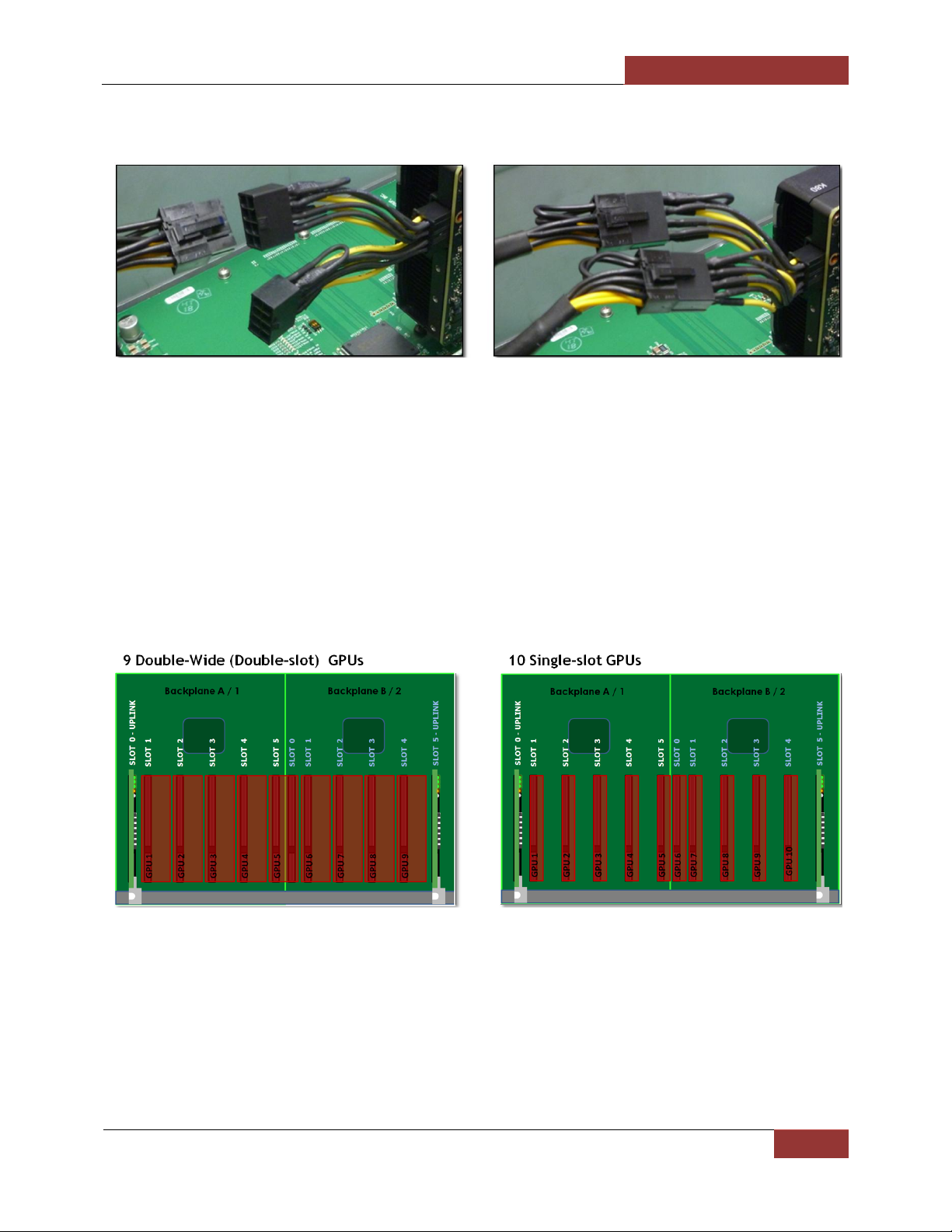
Double-wide GPUs vs. Single-slot GPUs
When installing double-wide GPUs in the expansion unit, you can only fit 9 GPUs. With single-slot GPU you
can fit 10.
There are two backplanes in the expansion chassis with 10 available PCIe slots combined.
Backplane A/1, can accommodate 5 double-wide GPUs or 5 single-slot GPUs
Backplane B/2, you can only fit 4 double-wide GPUs or 5 single-slot GPUs
A double-wide GPU takes up two PCIe slots. To address this issue, we enlarged the space in-between two
slots on the backplane. The EB3600-AB expansion backplane can accommodate multiple double-wide
GPUs.
Page 45

Magma
EB3600-AB | Chapter 2 Hardware Installation
45
110V
220V
15 amps x 110 volts = 1650 watts
15 amps x 220 volts = 3300
20 amps x 110 volts = 2200 watts
20 amps x 220 volts = 4400
30 amps x 110 volts = 3300 watts
30 amps x 220 volts = 6600
120V
230V
15 amps x 120 volts = 1800 watts
15 amps x 230 volts = 3450
20 amps x 120 volts = 2400 watts
20 amps x 230 volts = 4600
30 amps x 120 volts = 3600 watts
30 amps x 230 volts = 6900
Connect Power Cord / Cable
Plug: 15A 110-120V | Connector: 15A 110-120v. Magma only provides the 110-120v power cord. User can
also use 15A 220v-230v power cord / plug. Power Plug and Electrical outlets vary from country to country.
Plug-in all power cords to the expansion chassis. Each supplied power supply will come with a power cord.
Up to four Power Cords for EB3600-AB. A single expansion backplane has two power supply modules that
require 2 power cords.
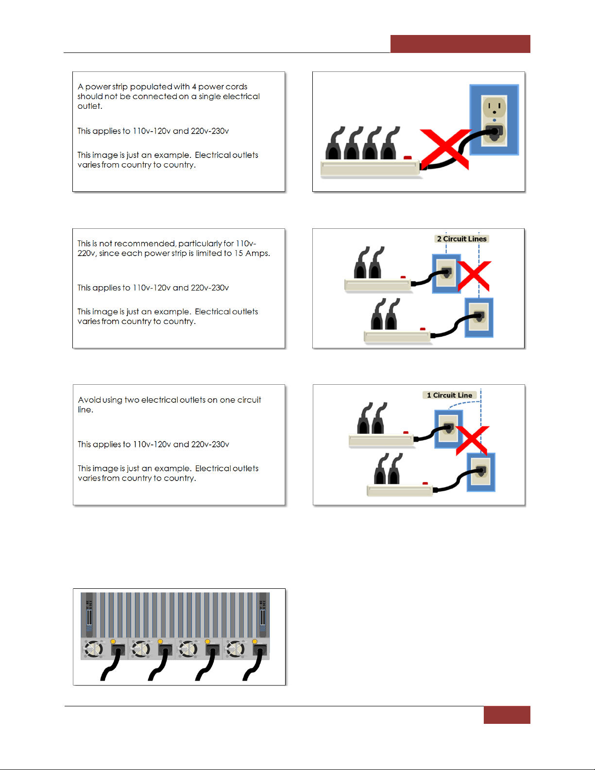
Connect to Electrical Outlets
Connect power cords to electrical outlets. When using four 110v power cords it is highly recommended to
connect them into two or more 110v electrical outlets on different circuit lines to prevent electrical
overloads. This also applies to 220v power plug. Be cautious, practice safe and correct methods when
powering up your EB3600-AB expansion unit. Pictures below are different configurations of supplying power
to the expansion unit.
Is it ok to connect four 1200W Power Supply modules to 120V?
Answer:
Using the above mathematical equations you can only run a single 1200W device on either 15 or 20 amp
lines regardless of whether it is 120 or 110 volts. One circuit for each 1200-watt device. The power supplies
will support up to 240V operation for other geographies. If you have 30 amp, 110 or 120-volt lines you can
run two 1200-watt devices.
Page 46

Magma
EB3600-AB | Chapter 2 Hardware Installation
46
WARNING
DO NOT use anything that uses the same amount of watts that your circuit can handle, for example, if
you have a 120 volt outlet on a 15 amp circuit the max for that outlet is 1800, thus you need to stay
WELL UNDER that amount. If you use exactly 1800 watts and the breaker does not trip then the
resistance of the wires and connections can heat up causing a fire. The further from the breaker box
the greater the resistance.
volts times amps = watts
watts divided by volts = amps
watts divided by amps = volts
Prior to powering up the system, we recommend that you check your breaker box for the amps for each
circuit, commercial buildings or homes are rated 120 volts (note that double breakers are double the
current, if your household voltage is 120 then double breakers are 240 volts).
In order to power up the system you would need sufficient circuits. Like other appliances, EB3600-AB
expansion unit requires a set amount of volts.
Use two separate circuit lines
Do not use multiple electrical outlets on one circuit line
Page 47
Magma
EB3600-AB | Chapter 2 Hardware Installation
47
Once you have plugged in all power cables to proper electrical outlets or turned the power strip switch to
ON position, all AMBER LEDs are immediately illuminated on the back of the power supply unit. Each power
supply module is designated with one indicator LED (see picture below).
Page 48

Magma
EB3600-AB | Chapter 2 Hardware Installation
48
Two Solid Green LEDs (3.3V) are illuminated on both backplanes when the power cable is connected. This
signifies the unit is on “standby mode.
Power ON the expansion unit
Press the power button on the front switch to power up the EB3600-AB-P unit. Turn on the expansion chassis
first before powering ON the host computer.
Check your installation before powering up expansion chassis for the first time. Although the power supply
has an over voltage protection device built into it, it may not "trip" in time to fully protect a device that has
been improperly connected, or whose power cable has been damaged.
You must apply power to the expansion chassis BEFORE you power up your computer. This will allow the
higher numbered buses in the bus hierarchy to be at a stable state when the host computer issues its
master power-on bus reset.
Each power supply has individual power LEDs to indicate its power status. The power supply has no power
switch that you can flip ON and OFF. Once the expansion unit (power cable) is plugged into an electrical
outlet the entire system is ready to be powered up through the main power switch (push button) located
on the front panel.
Green means the power supply is ON. Amber or orange, the power supply is standby mode.
Page 49

Magma
EB3600-AB | Chapter 2 Hardware Installation
49
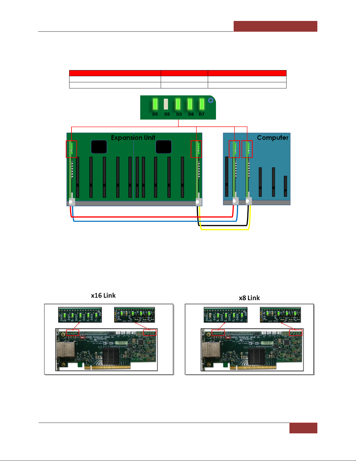
One solid Amber LED (D5) and three solid Green LEDs (D3, D8, and D7) are illuminated on the expansion
interface card. Upon connecting the power cable to an electrical outlet and applying power to the
expansion unit, the following LEDs are lit.
The LED on the top should turn AMBER when the power cord is connected to the device from the outlet.
When the front button On/Off switch is activated or pressed, the AC POWER LED should turn green.
Power ON Computer
To effectively use your Magma chassis as part of your computer system, ensure that all the proper
connections are made. Then power on your computer. This will enable your Magma chassis to turn ON.
Hardware Check
Once you have turned ON the Magma EB3600-AB and the host computer, the next thing to do is to check
the LED status on the hardware. Verify that the following LEDs on the expansion card, host card,
backplane, and front panel are illuminated.
Interface Card and Expansion card operating normally should show up with four Solid Green LEDs (see
picture below). Reset is de-asserted, LED D5 is turned off.
15 Solid Green LEDs on each backplane are illuminated (see picture below).
Check LED "PORT 0 - D9" status, see if it is illuminated solid green or blinking fast.
6 solid Green LEDs are lit on the front Panel Status LED indicator (see picture below).
Page 50
Magma
EB3600-AB | Chapter 2 Hardware Installation
50
LED
STATUS
COLOR
D4, D3, D8, and D8
ON
Solid Green
D5
OFF
None
Host & Expansion Interface cards LEDs
The picture below shows the number of Solid Green LEDS illuminated on both expansion an host interface
cards.
The picture below shows the number of solid green LEDS that are illuminated on the Expansion and Host
Interface cards when the unit is operating normally.
Page 51

Magma
EB3600-AB | Chapter 2 Hardware Installation
51
LED
STATUS
COLOR
D14, D12, D10, D8, D6, D4, D2, D42
ON
Solid Green
D1, D3, D5, D7, D9, D11, D13
ON
Solid Green
D33, D39, D40, D41, D43, D44, D16
OFF
None
D37, D36, D35, D33, D32, D15
OFF
None
Front Panel Status LEDs
6 solid Green LEDs are illuminated on the Front Panel Status indicator when the system is up and running.
Backplane LEDs
15 Solid Green LEDs (on each backplane) are illuminated when the system is turned on.
Page 52

Magma
EB3600-AB | Completing Hardware Set up
52
Completing Hardware Set up
Your hardware set up is now complete. You should have fully integrated all the GPUs in the EB360-AB
expansion unit and connected to host servers. The picture below shows what your EB3600-AB configuration
looks like after completing the set up.
Front view: All front LED indicators are ON
Page 53

Magma
EB3600-AB | Completing Hardware Set up
53
Top view layout of EB3600-AB attached to two servers
Top view layout EB3600-AB attached to one server
Page 54

Magma
EB3600-AB | Chapter 3 Software Installation
54
IMPORTANT
Magma requires no driver for Windows, Mac OS, Linux and other Operating Systems.
Chapter 3 Software Installation
Install Software
Skip this part; you do not need to install driver or software for the Magma EB3600-AB expansion unit.
Verify Installation
Windows
No additional software or drivers are needed. The operating system should automatically recognize the
Magma expansion chassis.
Magma
To verify a successful installation on Windows, find the ‘My Computer’ icon and “right click” on it. Then
select ‘Manage’ from the pop-up menu. Next, click on ‘Device Manager’ in the leftmost Computer
Management window. Finally, click on the View Menu and select View Devices by Connection.
to expand sub devices several times until your reach PCI
Express Root Port with a PCI Standard PCI-to-PCI Bridge beneath it.
Page 55

Magma
EB3600-AB | Chapter 3 Software Installation
55
The Device Manager will display the available slots within the chassis. As reference, you can determine
which slot you inserted your PCIe card in by following the outline that is shown below.
The Magma chassis has 2 PCIe Switch devices that enable the slots to work:
The 1st PCIe Switch controls Slots 1,2,3,4,5
The 2nd PCIe Switch controls slots 0,1,2,3,4,
If the verification is successful, you can install 3rd Party cards as well as auxiliary peripherals, such as hard
drives into the chassis.
Linux
Once the EB360-AB expansion unit has been installed in a Linux-based system, its installation can be verified
by typing the following command lines:
lspci –t Displays the overall structure of the PCIe expansion system
lspci –vv Lists additional information about the PCIe switch (in our case it will list the Integrated Device
Technology (IDT) information.
Ispci –vvv Displays the most comprehensive information about the expansion system.
Typical output from lspci –vvv is verbose, but you can dig through the information to find very important
information. There are so many registers and settings associated with PCI Express Switches.
For example, the image below is showing the Magma Chassis on Bus 2, Device 0, and Function 0. Some
information has been deleted, but notice the Link Supported Speed is 8GT/s, Width x16 . This is helpful to
know that the chassis is configured for x8 PCI Express Speeds highlighted in red
In order to obtain detailed information you must login as a sudo user in Linux and type “lspci –vv”
Page 56

Magma
EB3600-AB | Chapter 3 Software Installation
56
Use the “lspci | grep 8796” command to check that the Magma card slot devices are detected (see
image below).
Below is the output text of “lspci-vv”. Showing all Magma card slot devices with two GPU cards installed. Magma
devices are highlighted in red. Two GPUs plugged in are highlighted in green.
01:00.0 PCI bridge: PLX Technology, Inc. Device 8796 (rev a) (prog-if 00 [Normal decode])
Flags: bus master, fast devsel, latency 0
Memory at f7100000 (32-bit, non-prefetchable) [size=256K]
Bus: primary=01, secondary=02, subordinate=07, sec-latency=0
I/O behind bridge: 0000e000-0000efff
Memory behind bridge: f6000000-f70fffff
Prefetchable memory behind bridge: 00000000e0000000-00000000f1ffffff
Capabilities: [40] Power Management version 3
Capabilities: [48] MSI: Enable+ Count=1/8 Maskable+ 64bit+
Capabilities: [68] Express Upstream Port, MSI 00
Capabilities: [a4] Subsystem: PLX Technology, Inc. Device 8796
Capabilities: [100] Device Serial Number aa-87-00-10-b5-df-0e-00
Capabilities: [fb4] Advanced Error Reporting
Capabilities: [138] Power Budgeting <?>
Capabilities: [10c] #19
Capabilities: [148] Virtual Channel
Capabilities: [e00] #12
Capabilities: [b00] Latency Tolerance Reporting
Capabilities: [b70] Vendor Specific Information: ID=0001 Rev=0 Len=010 <?>
Page 57

Magma
EB3600-AB | Chapter 3 Software Installation
57
Kernel driver in use: pcieport
Kernel modules: shpchp
02:04.0 PCI bridge: PLX Technology, Inc. Device 8796 (rev aa) (prog-if 00 [Normal decode])
Flags: bus master, fast devsel, latency 0
Bus: primary=02, secondary=03, subordinate=03, sec-latency=0
Capabilities: [40] Power Management version 3
Capabilities: [48] MSI: Enable+ Count=1/8 Maskable+ 64bit+
Capabilities: [68] Express Downstream Port (Slot+), MSI 00
Capabilities: [a4] Subsystem: PLX Technology, Inc. Device 8796
Capabilities: [100] Device Serial Number aa-87-00-10-b5-df-0e-00
Capabilities: [fb4] Advanced Error Reporting
Capabilities: [138] Power Budgeting <?>
Capabilities: [10c] #19
Capabilities: [148] Virtual Channel
Capabilities: [e00] #12
Capabilities: [f24] Access Control Services
Capabilities: [b70] Vendor Specific Information: ID=0001 Rev=0 Len=010 <?>
Kernel driver in use: pcieport
Kernel modules: shpchp
02:08.0 PCI bridge: PLX Technology, Inc. Device 8796 (rev aa) (prog-if 00 [Normal decode])
Flags: bus master, fast devsel, latency 0
Bus: primary=02, secondary=04, subordinate=04, sec-latency=0
Capabilities: [40] Power Management version 3
Capabilities: [48] MSI: Enable+ Count=1/8 Maskable+ 64bit+
Capabilities: [68] Express Downstream Port (Slot+), MSI 00
Capabilities: [a4] Subsystem: PLX Technology, Inc. Device 8796
Capabilities: [100] Device Serial Number aa-87-00-10-b5-df-0e-00
Capabilities: [fb4] Advanced Error Reporting
Capabilities: [138] Power Budgeting <?>
Capabilities: [10c] #19
Capabilities: [148] Virtual Channel
Capabilities: [e00] #12
Capabilities: [f24] Access Control Services
Capabilities: [b70] Vendor Specific Information: ID=0001 Rev=0 Len=010 <?>
Kernel driver in use: pcieport
Kernel modules: shpchp
02:0c.0 PCI bridge: PLX Technology, Inc. Device 8796 (rev a) (prog-if 00 [Normal decode])
Flags: bus master, fast devsel, latency 0
Bus: primary=02, secondary=05, subordinate=05, sec-latency=0
Capabilities: [40] Power Management version 3
Capabilities: [48] MSI: Enable+ Count=1/8 Maskable+ 64bit+
Capabilities: [68] Express Downstream Port (Slot+), MSI 00
Capabilities: [a4] Subsystem: PLX Technology, Inc. Device 8796
Capabilities: [100] Device Serial Number aa-87-00-10-b5-df-0e-00
Capabilities: [fb4] Advanced Error Reporting
Capabilities: [138] Power Budgeting <?>
Capabilities: [10c] #19
Capabilities: [148] Virtual Channel
Capabilities: [e00] #12
Capabilities: [f24] Access Control Services
Capabilities: [b70] Vendor Specific Information: ID=0001 Rev=0 Len=010 <?>
Kernel driver in use: pcieport
Kernel modules: shpchp
02:10.0 PCI bridge: PLX Technology, Inc. Device 8796 (rev a) (prog-if 00 [Normal decode])
Flags: bus master, fast devsel, latency 0
Bus: primary=02, secondary=06, subordinate=06, sec-latency=0
Capabilities: [40] Power Management version 3
Capabilities: [48] MSI: Enable+ Count=1/8 Maskable+ 64bit+
Capabilities: [68] Express Downstream Port (Slot+), MSI 00
Capabilities: [a4] Subsystem: PLX Technology, Inc. Device 8796
Capabilities: [100] Device Serial Number aa-87-00-10-b5-df-0e-00
Capabilities: [fb4] Advanced Error Reporting
Capabilities: [138] Power Budgeting <?>
Capabilities: [10c] #19
Page 58

Magma
EB3600-AB | Chapter 3 Software Installation
58
Capabilities: [148] Virtual Channel
Capabilities: [e00] #12
Capabilities: [f24] Access Control Services
Capabilities: [b70] Vendor Specific Information: ID=0001 Rev=0 Len=010 <?>
Kernel driver in use: pcieport
Kernel modules: shpchp
02:14.0 PCI bridge: PLX Technology, Inc. Device 8796 (rev a) (prog-if 00 [Normal decode])
Flags: bus master, fast devsel, latency 0
Bus: primary=02, secondary=07, subordinate=07, sec-latency=0
I/O behind bridge: 0000e000-0000efff
Memory behind bridge: f6000000-f70fffff
Prefetchable memory behind bridge: 00000000e0000000-00000000f1ffffff
Capabilities: [40] Power Management version 3
Capabilities: [48] MSI: Enable+ Count=1/8 Maskable+ 64bit+
Capabilities: [68] Express Downstream Port (Slot+), MSI 00
Capabilities: [a4] Subsystem: PLX Technology, Inc. Device 8796
Capabilities: [100] Device Serial Number aa-87-00-10-b5-df-0e-00
Capabilities: [fb4] Advanced Error Reporting
Capabilities: [138] Power Budgeting <?>
Capabilities: [10c] #19
Capabilities: [148] Virtual Channel
Capabilities: [e00] #12
Capabilities: [f24] Access Control Services
Capabilities: [b70] Vendor Specific Information: ID=0001 Rev=0 Len=010 <?>
Kernel driver in use: pcieport
Kernel modules: shpchp
07:00.0 VGA compatible controller: NVIDIA Corporation GK107 [NVS 510] (rev a1) (prog-if 00 [VGA controller])
Subsystem: NVIDIA Corporation Device 0967
Flags: bus master, fast devsel, latency 0, IRQ 60
Memory at f6000000 (32-bit, non-prefetchable) [size=16M]
Memory at e0000000 (64-bit, prefetchable) [size=256M]
Memory at f0000000 (64-bit, prefetchable) [size=32M]
I/O ports at e000 [size=128]
[virtual] Expansion ROM at f7000000 [disabled] [size=512K]
Capabilities: [60] Power Management version 3
Capabilities: [68] MSI: Enable+ Count=1/1 Maskable- 64bit+
Capabilities: [78] Express Endpoint, MSI 00
Capabilities: [b4] Vendor Specific Information: Len=14 <?>
Capabilities: [100] Virtual Channel
Capabilities: [128] Power Budgeting <?>
Capabilities: [600] Vendor Specific Information: ID=0001 Rev=1 Len=024 <?>
Capabilities: [900] #19
Kernel driver in use: nvidia
Kernel modules: nouveau, nvidia
07:00.1 Audio device: NVIDIA Corporation GK107 HDMI Audio Controller (rev a1)
Subsystem: NVIDIA Corporation Device 0967
Flags: bus master, fast devsel, latency 0, IRQ 17
Memory at f7080000 (32-bit, non-prefetchable) [size=16K]
Capabilities: [60] Power Management version 3
Capabilities: [68] MSI: Enable- Count=1/1 Maskable- 64bit+
Capabilities: [78] Express Endpoint, MSI 00
Kernel driver in use: snd_hda_intel
Kernel modules: snd_hda_intel
0a:00.0 PCI bridge: PLX Technology, Inc. Device 8796 (rev a) (prog-if 00 [Normal decode])
Flags: bus master, fast devsel, latency 0
Memory at f5100000 (32-bit, non-prefetchable) [size=256K]
Bus: primary=0a, secondary=0b, subordinate=10, sec-latency=0
I/O behind bridge: 0000d000-0000dfff
Memory behind bridge: f4000000-f50fffff
Prefetchable memory behind bridge: 00000000c0000000-00000000d1ffffff
Capabilities: [40] Power Management version 3
Capabilities: [48] MSI: Enable+ Count=1/8 Maskable+ 64bit+
Capabilities: [68] Express Upstream Port, MSI 00
Capabilities: [a4] Subsystem: PLX Technology, Inc. Device 8796
Capabilities: [100] Device Serial Number aa-87-00-10-b5-df-0e-00
Page 59

Magma
EB3600-AB | Chapter 3 Software Installation
59
Capabilities: [fb4] Advanced Error Reporting
Capabilities: [138] Power Budgeting <?>
Capabilities: [10c] #19
Capabilities: [148] Virtual Channel
Capabilities: [e00] #12
Capabilities: [b00] Latency Tolerance Reporting
Capabilities: [b70] Vendor Specific Information: ID=0001 Rev=0 Len=010 <?>
Kernel driver in use: pcieport
Kernel modules: shpchp
0b:04.0 PCI bridge: PLX Technology, Inc. Device 8796 (rev a) (prog-if 00 [Normal decode])
Flags: bus master, fast devsel, latency 0
Bus: primary=0b, secondary=0c, subordinate=0c, sec-latency=0
Capabilities: [40] Power Management version 3
Capabilities: [48] MSI: Enable+ Count=1/8 Maskable+ 64bit+
Capabilities: [68] Express Downstream Port (Slot+), MSI 00
Capabilities: [a4] Subsystem: PLX Technology, Inc. Device 8796
Capabilities: [100] Device Serial Number aa-87-00-10-b5-df-0e-00
Capabilities: [fb4] Advanced Error Reporting
Capabilities: [138] Power Budgeting <?>
Capabilities: [10c] #19
Capabilities: [148] Virtual Channel
Capabilities: [e00] #12
Capabilities: [f24] Access Control Services
Capabilities: [b70] Vendor Specific Information: ID=0001 Rev=0 Len=010 <?>
Kernel driver in use: pcieport
Kernel modules: shpchp
0b:08.0 PCI bridge: PLX Technology, Inc. Device 8796 (rev a) (prog-if 00 [Normal decode])
Flags: bus master, fast devsel, latency 0
Bus: primary=0b, secondary=0d, subordinate=0d, sec-latency=0
Capabilities: [40] Power Management version 3
Capabilities: [48] MSI: Enable+ Count=1/8 Maskable+ 64bit+
Capabilities: [68] Express Downstream Port (Slot+), MSI 00
Capabilities: [a4] Subsystem: PLX Technology, Inc. Device 8796
Capabilities: [100] Device Serial Number aa-87-00-10-b5-df-0e-00
Capabilities: [fb4] Advanced Error Reporting
Capabilities: [138] Power Budgeting <?>
Capabilities: [10c] #19
Capabilities: [148] Virtual Channel
Capabilities: [e00] #12
Capabilities: [f24] Access Control Services
Capabilities: [b70] Vendor Specific Information: ID=0001 Rev=0 Len=010 <?>
Kernel driver in use: pcieport
Kernel modules: shpchp
0b:0c.0 PCI bridge: PLX Technology, Inc. Device 8796 (rev a) (prog-if 00 [Normal decode])
Flags: bus master, fast devsel, latency 0
Bus: primary=0b, secondary=0e, subordinate=0e, sec-latency=0
Capabilities: [40] Power Management version 3
Capabilities: [48] MSI: Enable+ Count=1/8 Maskable+ 64bit+
Capabilities: [68] Express Downstream Port (Slot+), MSI 00
Capabilities: [a4] Subsystem: PLX Technology, Inc. Device 8796
Capabilities: [100] Device Serial Number aa-87-00-10-b5-df-0e-00
Capabilities: [fb4] Advanced Error Reporting
Capabilities: [138] Power Budgeting <?>
Capabilities: [10c] #19
Capabilities: [148] Virtual Channel
Capabilities: [e00] #12
Capabilities: [f24] Access Control Services
Capabilities: [b70] Vendor Specific Information: ID=0001 Rev=0 Len=010 <?>
Kernel driver in use: pcieport
Kernel modules: shpchp
0b:10.0 PCI bridge: PLX Technology, Inc. Device 8796 (rev a) (prog-if 00 [Normal decode])
Flags: bus master, fast devsel, latency 0
Bus: primary=0b, secondary=0f, subordinate=0f, sec-latency=0
I/O behind bridge: 0000d000-0000dfff
Memory behind bridge: f4000000-f50fffff
Page 60

Magma
EB3600-AB | Chapter 3 Software Installation
60
Prefetchable memory behind bridge: 00000000c0000000-00000000d1ffffff
Capabilities: [40] Power Management version 3
Capabilities: [48] MSI: Enable+ Count=1/8 Maskable+ 64bit+
Capabilities: [68] Express Downstream Port (Slot+), MSI 00
Capabilities: [a4] Subsystem: PLX Technology, Inc. Device 8796
Capabilities: [100] Device Serial Number aa-87-00-10-b5-df-0e-00
Capabilities: [fb4] Advanced Error Reporting
Capabilities: [138] Power Budgeting <?>
Capabilities: [10c] #19
Capabilities: [148] Virtual Channel
Capabilities: [e00] #12
Capabilities: [f24] Access Control Services
Capabilities: [b70] Vendor Specific Information: ID=0001 Rev=0 Len=010 <?>
Kernel driver in use: pcieport
Kernel modules: shpchp
0b:14.0 PCI bridge: PLX Technology, Inc. Device 8796 (rev a) (prog-if 00 [Normal decode])
Flags: bus master, fast devsel, latency 0
Bus: primary=0b, secondary=10, subordinate=10, sec-latency=0
Capabilities: [40] Power Management version 3
Capabilities: [48] MSI: Enable+ Count=1/8 Maskable+ 64bit+
Capabilities: [68] Express Downstream Port (Slot+), MSI 00
Capabilities: [a4] Subsystem: PLX Technology, Inc. Device 8796
Capabilities: [100] Device Serial Number aa-87-00-10-b5-df-0e-00
Capabilities: [fb4] Advanced Error Reporting
Capabilities: [138] Power Budgeting <?>
Capabilities: [10c] #19
Capabilities: [148] Virtual Channel
Capabilities: [e00] #12
Capabilities: [f24] Access Control Services
Capabilities: [b70] Vendor Specific Information: ID=0001 Rev=0 Len=010 <?>
Kernel driver in use: pcieport
Kernel modules: shpchp
0f:00.0 VGA compatible controller: NVIDIA Corporation GK107 [NVS 510] (rev a1) (prog-if 00 [VGA controller])
Subsystem: NVIDIA Corporation Device 0967
Flags: bus master, fast devsel, latency 0, IRQ 61
Memory at f4000000 (32-bit, non-prefetchable) [size=16M]
Memory at c0000000 (64-bit, prefetchable) [size=256M]
Memory at d0000000 (64-bit, prefetchable) [size=32M]
I/O ports at d000 [size=128]
[virtual] Expansion ROM at f5000000 [disabled] [size=512K]
Capabilities: [60] Power Management version 3
Capabilities: [68] MSI: Enable+ Count=1/1 Maskable- 64bit+
Capabilities: [78] Express Endpoint, MSI 00
Capabilities: [b4] Vendor Specific Information: Len=14 <?>
Capabilities: [100] Virtual Channel
Capabilities: [128] Power Budgeting <?>
Capabilities: [600] Vendor Specific Information: ID=0001 Rev=1 Len=024 <?>
Capabilities: [900] #19
Kernel driver in use: nvidia
Kernel modules: nouveau, nvidia
0f:00.1 Audio device: NVIDIA Corporation GK107 HDMI Audio Controller (rev a1)
Subsystem: NVIDIA Corporation Device 0967
Flags: bus master, fast devsel, latency 0, IRQ 17
Memory at f5080000 (32-bit, non-prefetchable) [size=16K]
Capabilities: [60] Power Management version 3
Capabilities: [68] MSI: Enable- Count=1/1 Maskable- 64bit+
Capabilities: [78] Express Endpoint, MSI 00
Kernel driver in use: snd_hda_intel
Kernel modules: snd_hda_intel
Page 61

Magma
EB3600-AB |
61
Check / Verify PCIe cards / GPU
You can check or verify the status of your PCIe cards or GPUs that are installed in the expansion unit using
the “PCIe Info”. For more details on how to access and use the PCIe Info via Management console Go
to Chapter 5, PCIe Info,
In Linux operating system you can use the following commands to check if the GPUs or PCIe cards are
detected or not.
Use the “lspci -vtt”
Use the “ lspci | grep NVIDIA”, see picture below. You can replace NVIDIA with another name of
GPUs or PCIe cards.
Page 62

Magma
EB3600-AB | Chapter 4 General & Technical Information
62
Chapter 4 General & Technical Information
EB3600-AB
Top view
Page 63

Magma
EB3600-AB | Chapter 4 General & Technical Information
63
Rear view
Placement of GPUs on the expansion backplane
The EB3600 has two backplanes / motherboard with 10 available PCIe slots combined. Each backplane
has 5 PCIe slots and can accommodate 5 singlewide GPUs.
Backplane A /1
5 PCIe slots can accommodate 5 single-wide GPUS or 5 double-wide GPUs
Backplane B/2
5 PCIe slot can accommodate 5 single-wide GPUS, but can only accommodate 4 double-wide
GPS
Page 64

Magma
EB3600-AB | Chapter 4 General & Technical Information
64
EB3600-AB with 10 “single-wide” GPUs
EB3600-AB with 9 “double-wide” GPUs
Page 65

Magma
EB3600-AB | Chapter 4 General & Technical Information
65
Proper Placement of GPUs
Different placement configurations of double-wide GPUs on the backplane of the EB3600-AB are illustrated
below.
For example, when running 4 GPUs you must equally distribute the number of GPUs that you are installing
on each backplane. It will be 2 on the first side of the backplane A and the remaining 2 on the other side
of backplane B.
Page 66

Magma
EB3600-AB | Chapter 4 General & Technical Information
66
Page 67

Magma
EB3600-AB | Chapter 4 General & Technical Information
67
Page 68

Magma
EB3600-AB | Chapter 4 General & Technical Information
68
Page 69

Magma
EB3600-AB | Chapter 4 General & Technical Information
69
Backplane PCIe slots and Ports assignment
Each PCIe slot has its own port assignment, see picture below. There are 12 PCIe slots on the EB3600-AB
backplane, two are occupied by the Expansion interface card and 10 slots are available. All 12 slots have
their own corresponding port. The port assignment are hard-coded, you cannot change or modify this
information.
For example, a single GPU or PCIe card is plugged into slot 2 on the backplane B, port 16 will be
automatically assigned to the card.
Page 70

Magma
EB3600-AB | Chapter 4 General & Technical Information
70
LEDs
DESCRIPTION
When Lit (Solid Green or blinking)
When Off
1st Bank
3v3SL2 (D38)
Debug
N/A
NA
3V3SL3 (D39)
Debug
N/A
NA
3V3SL4 (D40)
Debug
N/A
NA
3V3SL5 (D41)
Debug
N/A
NA
RESET (D42)
PCIe Reset
EB3600-AB is in reset
EB3600-AB is out of reset
DEBUG (D43)
Debug
N/A
NA
0V9A (D2)
900 mV Analog Power
Solid - power rail OK
OFF - power rail out of range
3V3 CLK (D4)
3.3V Clock Power
Solid - power rail OK
OFF - power rail out of range
1V8A (D6)
1.8V Analog Power
Solid - power rail OK
OFF - power rail out of range
0V9 (D8)
Debug
N/A
N/A
PORT4 (D10)
Slot 5 Link
Solid - Gen 3 Link
Fast Blinking - Gen 2 Link,
Slow Blinking - Gen 1 Link
OFF – not Linked
PORT 12 (D12)
Slot 4 Link
Solid - Gen 3 Link
Fast Blinking - Gen 2 Link,
Slow Blinking - Gen 1 Link
OFF – not Linked
PORT 20 (D14)
Slot 3 Link
Solid - Gen 3 Link
Fast Blinking - Gen 2 Link,
Slow Blinking - Gen 1 Link
OFF – not Linked
12V SL1 (D16)
Debug
NA
NA
Backplane and LEDs
a. 10 PCIe x16 slot ( electrical and mechanical)
b. Two designated Link-Up SLOTs for Interface card (see picture below)
c. Slot LEDs, Link and Activity LEDs (see below)
Page 71

Magma
EB3600-AB | Chapter 4 General & Technical Information
71
LEDs
DESCRIPTION
When Lit (Solid Green or blinking)
When Off
2nd Bank
0V9 (D1)
900mV I/O Power
Solid - power rail OK
OFF - power rail out of range
3V3 (D3)
3.3V System Power
Solid - power rail OK
OFF - power rail out of range
1V8 (D5)
1.8V System Power
Solid - power rail OK
OFF - power rail out of range
1V8 AUX (D7)
1.8V Aux System Power
Solid - power rail OK
OFF - power rail out of range
PORT 0 (D9)
Slot 0 Link
Solid - Gen 3 Link; Fast Blinking - Gen 2 Link, Slow
Blinking - Gen 1 Link
OFF - Not Linked
PORT 8 (D11)
Slot 1 Link
Solid - Gen 3 Link; Fast Blinking - Gen 2 Link, Slow
Blinking - Gen 1 Link
OFF - Not Linked
PORT 16 (D12)
Slot 2 Link
Solid - Gen 3 Link; Fast Blinking - Gen 2 Link, Slow
Blinking - Gen 1 Link
OFF - Not Linked
12VSL0 (D15)
Debug
NA
NA
12VSL2 (D32)
Debug
NA
NA
12VSL3 (D33)
Debug
NA
NA
12VSL4 (D34)
Debug
NA
NA
12VSL5 (D35)
Debug
NA
NA
3V3SL0 (D36)
Debug
NA
NA
RESET (D42)
PCIe Reset
EB3600-AB is in reset
EB3600-AB is out of reset
DEBUG (D43)
Debug
NA
NA
DEBUG (D44)
Debug
NA
NA
0V9A (D2)
900 mV Analog Power
Solid - power rail OK
OFF - power rail out of range
3V3 CLK (D4)
3.3V Clock Power
Solid - power rail OK
OFF - power rail out of range
1V8A (D6)
1.8V Analog Power
Solid - power rail OK
OFF - power rail out of range
SLOT#
LED
Description
When Lit (Solid Green or blinking)
When Off
Slot 0
PORT 0 (D9)
Slot 0 Link
Solid - Gen 3 Link;
Fast Blinking - Gen 2 Link,
Slow Blinking - Gen 1 Link
OFF - Not Linked
Slot 1
PORT 8 (D11)
Slot 1 Link
Solid - Gen 3 Link;
Fast Blinking - Gen 2 Link,
Slow Blinking - Gen 1 Link
OFF - Not Linked
Slot 2
PORT 16 (D12)
Slot 2 Link
Solid - Gen 3 Link;
Fast Blinking - Gen 2 Link,
Slow Blinking - Gen 1 Link
OFF - Not Linked
Slot 3
PORT 20 (D14)
Slot 3 Link
Solid - Gen 3 Link
Fast Blinking - Gen 2 Link,
Slow Blinking - Gen 1 Link
OFF – not Linked
Slot 4
PORT 12 (D12)
Slot 4 Link
Solid - Gen 3 Link
Fast Blinking - Gen 2 Link,
Slow Blinking - Gen 1 Link
OFF – not Linked
Slot 5
PORT4 (D10)
Slot 5 Link
Solid - Gen 3 Link
Fast Blinking - Gen 2 Link,
Slow Blinking - Gen 1 Link
OFF – not Linked
Card Slot Link LEDs
Page 72

Magma
EB3600-AB | Chapter 4 General & Technical Information
72
Interface Card
1
Link Width LED indicators
2
SW3, dip switches for speed / lane settings
3
Reset & Power Status LEDs
4
Rx Hint and Tx presets
5
Cable ports, x8-A and x16-B
6
SW4, toggle switch for interface mode setting (host or expansion)
7
Heatsink
Interface Card and LEDs
Interface card is x16
It is capable of operating at x16, x8 , x4 , x2 and x1 link widths
When the Amber LED (D5) is ON, the Reset is Asserted
When the Amber LED (D5) is OFF, it is de-asserted
When Interface card is being used as Host, need to set to OFF. For expansion set to ON.
During normal operation LEDs D7, D8 and D3 should be on and solid green at all times. If any of these LEDs
are off it means that there is a power problem with the unit.
LED D5 will turn on (Amber) when PCIe reset is asserted and turn off when the reset is de-asserted.
If any of the Interface cables are not connected correctly, the LED D5 will stay ON (Amber). Once the
cables are connected correctly and the expansion board is powered on and the host is turned on then the
amber LED D5 should be off.
Page 73

Magma
EB3600-AB | Chapter 4 General & Technical Information
73
Display Functions of Interface card LEDs
1. Link width mode.
If the LEDs are lit solid, then it is a gen 3 link. If not the alternate display will be activated.
2. Phase equalization mode.
D400: will not be lit.
D401: Phase equalization complete.
D402: Phase 3 successful.
D403: Phase 2 successful.
D404: Phase 1 successful.
For any link below gen 3, the display will alternate between these two. A 75% on 25% off duty cycle
indicates a gen 2 link whereas a 25% on 75% off duty cycle is a gen 1 link.
Page 74

Magma
EB3600-AB | Chapter 4 General & Technical Information
74
LED
Name
Description / Functions
When
OFF
When
ON
D5
reset
PCIe fundamental reset. When ON system is in reset and/or the high
speed cables have been connected incorrectly. When off while the
main power is ON, the system is out of PCIe reset
deasserted
asserted
D4
PCIe clock
present
Lights up if a PCIe clock has been detected
No clock
present
Clock is
present
D3
3.3V good
When on means that the locally generated 3.3V is good and within
specification. When off means that there is a problem with the local
3.3V
3.3V is bad
3.3V is
good
D8
1.0V good
When on means that the locally generate 1.0V is good and within
specification. When off means that there is a problem with the local
1.0V
1.0V is bad
1.0V is
good
D7
1.0V good
When on means that the locally generate 1.0V is good and within
specification. When off means that there is a problem with the local
1.0V
1.0V is bad
1.0V is
good
Reset & Power Status LEDs
LEDs D4, D3, D8, AND D7 when illuminated signify “power is good” (see table below).
Page 75

Magma
EB3600-AB | Chapter 4 General & Technical Information
75
Front Panel Status LEDs
LEDs on the front panel monitor internal temperature and show status of fans and power supplies. All LED's
should be green at all times. An orange LED means a fault of the corresponding item. The locator LED and
locator switches on the front and back panel locate the chassis in a rack installation. Push the switch on
either end of the chassis and the LED will blink on both front and back. Pressing either switch again, on
either side of the chassis will turn the LED off.
Should a problem occur with the chassis we included below explanations as to what all these items are
and how they should be treated.
Under normal operating conditions the status indicator LED’s should be green at all times. An orange LED
means a fault of the corresponding item listed in the picture above. If the chassis is functioning improperly,
you have the option of resetting the entire system by pressing and holding the Alarm Reset button (shown
in the above diagram) until the LEDs blink. The color of the LEDs will turn orange. This will enable the entire
device to reboot to its default settings. You can only do this once the chassis is turned off, but still operates
on standby power. So, ensure the power cable is connected between the chassis and the AC outlet.
Fan LEDs
Temperature Sensor Alarm LEDs
Page 76

Magma
EB3600-AB | Chapter 4 General & Technical Information
76
Power Supply Indicator LEDs
If the LED stays Orange after replacing or swapping the faulty component, you have to reset the SNMP to
factory default settings. Hold the Alarm Reset button (see picture below) until the LEDs blink. The color of
the entire LEDs will turn orange and the device will reboot to its default settings, all LEDs should turn on solid
Green.
Control Switches
There are four control switches on the interface card: SW1, SW2, SW3 and SW4
Page 77

Magma
EB3600-AB | Chapter 4 General & Technical Information
77
SW1 and SW2
SW1 and SW2 should not be altered or changed.
See screenshot below for their corresponding combination of dipswitch settings.
SW3
Link width can be changed by using the following dipswitch settings. By default, the card is set to x16.
SW4
Toggle switch for interface mode setting , the interface card can be used either host or expansion . Below
are the two mode-settings for the interface card.
Page 78

Magma
EB3600-AB | Chapter 4 General & Technical Information
78
ITEM
DESCRIPTION
Rated Voltage
12 VDC
Operation Voltage
7.0-13.2 VDC
Input Current
3.10 (3.72 max) A
Input Power
37.20 (44.64 max) W
Speed
8000 RPM
Max Air Flow
(at Zero Static Pressure)
4.957 (min 4.461) m3/min
175.03 (min 157.52)CFM
Max Air Pressure
(at Zero Air Flow)
46.21 (min 37.43 ) mnH20
1.819 (min 1.473) inchH20|
Acoustical Noise (AVG)
66.5 (Max 71.5) dB-A
Installation Type
UL: Class A
Operating Temp
10 to +60 Deg C
Storage Temp
-40 to +70 Deg C
Operating Humidity
5 to 90% RH
Storage Humidity
5 to 95 RH
Fan
EB3600-AB expansion unit has four fans installed enough to provide cooling to the extreme-high-heatgenerating GPUs. These are high CFM / RPM and replaceable fans.
The picture below is the top view of the EB3600-AB unit (viewing from the back-end) showing the order of
fans starting from left to right. Each fan is labeled with a number that corresponds to their fan-slot
assignment on SNMP web management. Fan#1 is located on the far left side of the expansion chassis and
Fan#4 is on the far right side of the expansion unit.
Fan Specs
92mm X 92mm X 38mm FAN, 185 CFM.
Page 79

Magma
EB3600-AB | Chapter 4 General & Technical Information
79
Fan Replacement
EB3600-AB is designed to allow fan replacement while the chassis is powered on. First you will need to
remove the chassis lid. Then locate the fan that has failed, unlock its thumbscrew, lift up its metal tab and
pull it out. Insert the new fan in and secure it in place. Verify the new fan is spinning and restore the chassis
lid.
Page 80

Magma
EB3600-AB | Chapter 4 General & Technical Information
80
SNMP / Netburner
The Interface board for the Netburner module provides simple Ethernet connectivity allowing you to have
direct and quick access to control devices such as the fan, power supply, and temperature and PCIe slots
via the SNMP Web Management. The Netburner is programmed with custom SNMP Web GUI for managing
and monitoring devices.
NetBurner Module
Replacing the NetBurner
If you need to replace your defective or non-functional NetBurner module follow the instructions below.
Position the expansion unit on its side to gain access to the NetBurner module. Unplug the Ethernet cable.
Page 81

Magma
EB3600-AB | Chapter 4 General & Technical Information
81
Lift the NetBurner card out of the interface board with two hands by placing both index fingers underneath
the side of the card and both thumbs on the topside of the card, see pictures below.
Use firm upward pressure underneath the card and a gentle rocking motion until the card comes loose, see
pictures below.
Page 82

Magma
EB3600-AB | Chapter 4 General & Technical Information
82
Netburner Installation
Align the Netburner module on top of the Interface board connectors.
Gently apply pressure on top of the Netburner module and slowly press it down until the board is firmly
seated.
Reconnect the Ethernet cable to the RJ45 port.
Page 83

Magma
EB3600-AB | Chapter 4 General & Technical Information
83
Replacing the Interface Board
Disconnect all the wires including the Ethernet cable from the board, see picture below. Remove screw
and nuts, see picture below.
Remove the interface board.
Page 84

Magma
EB3600-AB | Chapter 4 General & Technical Information
84
Netburner Interface Board Installation
To install the new Interface board, just follow the previous steps in reverse order.
Place the board in the chassis and align it on top of the 4 mounting screw-holes. Secure the board.
Connect all wires and plug in the Ethernet cable.
Page 85

Magma
EB3600-AB | Chapter 4 General & Technical Information
85
Power Supply unit
Configurable and replaceable power supply solutions of (1200W, 2400W, 3600W or 4800W).
Magma EB3600-AB Expansion chassis uses a redundant power supply with the ability to easily replace a
power module in the event of a failure. It includes two replaceable modules that share the power load
requirements during normal operations.
Should one module fail for any reason, the power load will be shifted to the other module.
An indicator for the failure would be the LEDs on the back panel of the power supply behind the
chassis.
For non-functioning equipment, these indicators would not show.
In case of power supply failure the audible alarm would be initiated to alert you on this condition. If this is
the case, press the black button on the status panel on the front of the unit to stop the audible alert.
How to replace the power supply module
Put the Magma EB3600-AB to standby mode or turn it OFF.
Unscrew the thumbscrews located on the back, simply grab the handle, and pull.
Insert the new power supply module. Secure the power supply.
Turn ON the Magma EB3600-AB expansion unit.
Page 86

Magma
EB3600-AB | Chapter 4 General & Technical Information
86
If the alarm continues, you need to reset the system to default setting by pressing and holding the Alarm
Reset button (shown in the above diagram) until the LEDs blink. The color of the LEDs will turn orange. This
will enable the entire device to reboot to its default settings. You can only do this once the chassis is turned
off, but is still operating in standby power. So, ensure the power cable is connected between the chassis
and the AC outlet.
Each power supply module is labeled with a number that corresponds to their PSU-slot assignment on SNMP
web management. PSU#1 is located on the far left side of the expansion chassis and PSU#4 is on the far
right side of the expansion unit. The “Input Rating” (110-240) label is located on top of the power supply
module.
Page 87

Magma
EB3600-AB | Chapter 4 General & Technical Information
87
How to Add Power Module to EB3600
Steps on how to add two additional power supply modules to EB3600-AB unit.
Power Supply Specifications
Scope
This document defines a series of power supply systems with the output power of up to 1200W and with
+12V & +5Vsb output rails or ATX output rails for 1U system application.
The power supply system consists of one (1), or two (2) power supply modules providing the +12V & +5Vsb
output rails and one (1) power distribution backplane providing the removable or redundancy function of
the power supply modules and also generating the +5V, +3.3V, and -12V output rails which are powered by
+12V output.
Page 88

Magma
EB3600-AB | Chapter 4 General & Technical Information
88
The power supply module is capable of replacing / exchanging with active current sharing and/or isolation
MOSFETs built in for +12V output, and droop current sharing and/or isolation diode built in for +5Vsb output.
The AC input is rated 90-264Vrms with power factor corrected (PFC > 0.95). A 38mm high reliable Sanyo
Denki fan is installed to the power supply module for cooling the power supply module, power devices on
the distribution backplane and part of the system.
AC Input
Table 1 lists AC input voltage and frequency range for continuous operation. The power supply is capable
of supplying full-rated output power over the input voltage ranges specified.
a) The inrush current of power supply module is less than 120A under the conditions of 240Vrms input and
25oC ambient cold start. The inrush current is limited to the extent that no damage will be done to the
power supply
under any specified line, load, and temperature conditions.
b) The leakage current of the power supply module is less than 1.5 mA measured at 264Vac input.
c) The repetitive ON/OFF cycling of AC input voltage will not damage the power supply.
d) The power supply can automatically recover from AC power loss.
e) The power supply is equipped with primary fuse for input over-current protection, and meets product
safety requirement.
DC Output
DC Output Voltage Regulations
The DC output voltages remain within the regulation ranges shown in Table 2 for both the power supply
module and the completed power system when measured at the load end of the output connectors
under all AC line, O/P loads, and environmental conditions.
a) The remote sensing is provided to +12V, +5V, and +3.3V outputs to compensate for excessive cable
drops.
b) +5V, +3.3V, and -12V outputs are located on the power distribution backplane.
DC Output Load Distributions
The Table 3 defines the power supply typical output load distribution.
Page 89

Magma
EB3600-AB | Chapter 4 General & Technical Information
89
a) The total continuous output power is 750W~1200W max. For one (1) or two (2) modules installed.
b) The peak current of +12V output is 110% of max rated current and may last for 15 msec.
c) No minimum load is required to +5V, +3.3V, -12V and +5Vsb outputs.
DC Output Efficiency (power supply module)
The power supply efficiency is 80% minimum measured at 20%, 50%, full load and nominal line input, which
is 115Vrms and 230Vrms conditions.
Output Protection
Over Voltage Protection
The power supply can provide latch-mode over voltage protection as defined in Table 8.
Over Current Protection
130% maximum for +12V output
150% maximum for +3.3V and +5V outputs
Short-circuit Protection
The power supply will shut down and latch off for shorting the +12VDC, +5VDC, and +3.3VDC rails to return
or any other rails. Shorts between main output rails and +5Vsb will not cause any damage to the power
supply. The power supply will shut down and latch off for shorting the negative rail. +5Vsb is capable of
being shorted indefinitely, but when the short is removed, the power supply will recover automatically or by
cycling PS_ON. The power supply is capable of withstanding a continuous short circuit to the outputs
without damage or overstress to the unit.
No-load Operation
No damage or hazardous condition will occur with all the DC output connectors disconnected from the
load. The power supply may latch into the shutdown state.
Isolation
Primary to Secondary 4242Vdc
Primary to Earth GND 2800Vdc
Page 90

Magma
EB3600-AB | Chapter 4 General & Technical Information
90
Output Signals (Redundant System)
Audible Alarm & Power Fail Signal
The Audible alarm and Power Fail signal are available from the signal card located on the backplane. The
audible alarm is silent and the Power Fail signal is "High" when all power modules are functioning properly.
The audible alarm will sound and the Power Fail signal will be "Low" under the following conditions :
a. One of the power supply modules is not functioning and is still attached to the backplane.
b. One of the power supply modules is attached to the backplane without an AC power cord plugged in.
Removing the not functioning power module from the backplane or pushing the reset switch provided will
reset the audible alarm and also the Power Fail signal.
LED light
The LED light installed on the power supply module is functioning as following:
a. Green color – Power module is ON and working properly.
b. Amber color – Power module is under Standby Mode or has default.
c. No color – No AC Power Connection.
Environmental
The following subsections define recommended environmental specifications and test parameters. Based
on the typical conditions to which a power supply may be subjected during operation or shipment.
Temperature
Operating -10oC to +50oC
Non-operating -40oC to +85oC
Humidity
Operating 10% to 90% relative humidity (non-condensing).
Non-operating 5% to 95% relative humidity (non-condensing)
Altitude
Operating 0 to 16,000 feet (5000 meter)
Storage 0 to 50,000 feet
Mean Time between Failures (MTBF)
100K hours minimum at full load 25oC
Page 91

Magma EB3600-AB | Chapter 5 Management Console I/O Manager
91
Chapter 5 Management Console I/O Manager
IMPORTANT
For compatibility and best performance it is highly recommended to use Google Chrome
as the primary web browser and Firefox as the secondary.
EB3600-AB contains extra features that could be utilized to monitor the status of the components on the
backplane and the items in the chassis such as the state of the power supplies, fan status, and
temperature. It is observed on a remote computer if an equipment malfunction has occurred.
SNMP Features
EB3600-AB supports the Simple Network Management Protocol (SNMP) for remote monitoring and
administration by offering the following features:
Internal Temperature monitoring
Clear Alarm button monitoring
Replaceable fan status (for fans 1,2,3 and 4 in the front)
Power supply 1 status
Power supply 2 status
Power supply 3 status
Power supply 4 status
Traps are defined to alert the SNMP server in case of overheating or failure in any of the subsystems
mentioned above
Remote chassis turn on
Remote Audible Alarm
Remote Turn on Locator LED
Serviceable Server A or B (Side A or Side B)
Web Access and SNMP Configuration
To ensure that you can successfully monitor your new system, you will need to connect it to a local or
private hub using a standard RJ-45 Ethernet Cable. To obtain access to the Magma chassis, direct your
web browser to the given IP address: 192.168.1.10. You must configure your network on this same domain
for this to work. Later, you can change the IP address to another domain or to use DHCP
Supported Internet Browser
Google Chrome
Firefox
Page 92
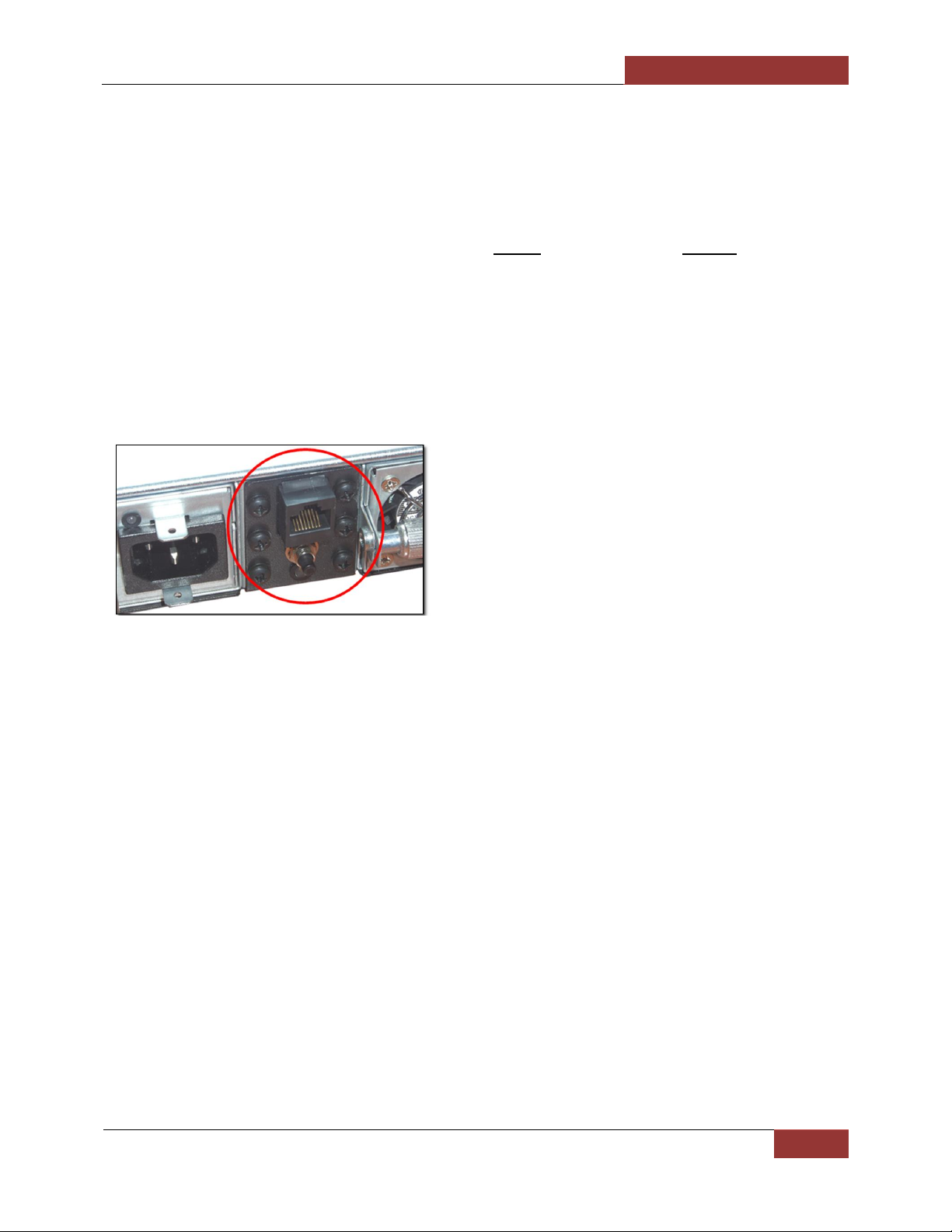
Magma EB3600-AB | Chapter 5 Management Console I/O Manager
92
To Access Express IO Manager / SNMP
1. Connect Ethernet cable to Magma EB3600-AB and Host computer.
2. Configure Network adapter settings
3. Launch Internet browser ( recommend to use Google Chrome or Firefox). Enter the IP
address in the URL 192.168.1.10, then press “ENTER”
4. Authentication login comes up. Enter “default” for User Name and magma for Password.
5. The user will be directed to the MAGMA Express IO Manager default home webpage.
Connect Ethernet Cable
Connect one end of the cable to the RJ-45 port, located to the top of the Expansion Interface card (back
of the chassis). Connect the other end to your local area network connector or any computer. In case you
connect the chassis to a local computer/laptop, be sure to use a Hub with a regular network cable or a
crossover cable without a Hub.
Configure Network Setting
Configure your computer’s network setting to correlate to the default IP address of the Magma chassis .
The IP address of the Magma chassis is 192.168.1.10.
Set your network settings to configure manually and enter an IP address for your computer of 192.168.1.40
where 40 can really be any free number other than 10. To verify we have successfully detected the
Magma Expansion chassis on our network open your web browser and direct it to the IP address of the
chassis that is 192.168.1.10.
How to configure your network setting in Windows OS
This setting is applicable to Windows 7, 8 and Windows server.
You need to disconnect your laptop or desktop computer prior to setting up the Network adapter.
1. Go to your computer
2. Right click the " network icon" below the system tray
3. Click "Open Network & Sharing Center"
4. Click Local Area Network
5. Click Properties
a. Select "Internet Protocol Version 4 (TCP/IPV4)
b. Click Properties
Page 93

Magma EB3600-AB | Chapter 5 Management Console I/O Manager
93
6. Select "Use the following IP address"
a. For IP address enter 192.168.1.20
b. For Subnet mask enter 255.255.255.0
7. Click OK
How to configure your network setting in Linux / Ubuntu
1. Start or launch the Terminal window.
2. Stop Network Manager by typing service NetworkManager stop command in the terminal.
3. Type sudo ifconfig eth0 192.168.1.40 netmask 255.255.255.0 ( see screenshot below).
4. Type route add default gw 192.168.1.1
5. Then press enter to accept the new settings.
6. You need to restart the network by typing service network restart command in the terminal.
7. Type ifconfig, to check and verify that the new IP address and Subnet mask have been accepted
(see screenshot below).
When done, you can reset the Network Adapter IP address and restart your Network Manager.
Page 94

Magma EB3600-AB | Chapter 5 Management Console I/O Manager
94
reset the Network Adapter IP address, sudo ip addr flush eth0 command in the terminal.
restart your Network Manager , type service NetworkManager start command in the terminal.
Launch Internet Browser
For Windows OS, open your internet browser and enter the IP address in the URL 192.168.1.10 window.
For Linux / Ubuntu, type xdg-open http://192.168.1.10 on the terminal window (see screenshot below).
If you are getting an error or unable to start the Express IO Manager check your Ethernet cable connection.
Make sure the Ethernet cable is plugged in and firmly inserted. Check to see if the cable has been cut,
chewed, or otherwise damaged. If it is damaged or broken please replace it with a known good cable.
Authentication Log-in
The Authentication login for the browser will appear. The define username will be “default” and the
password to be “magma”.
Windows Log-in screen:
Page 95

Magma EB3600-AB | Chapter 5 Management Console I/O Manager
95
Linux / Ubuntu Log-in screen:
Default Home Webpage
The user will be directed to the MAGMA home webpage for the expansion device. See screenshot
below as the default home webpage.
Management Console / Web GUI
HOME
The HOME page provides an overview for the status of the chassis. It allows you to view the number of fans,
power supplies, and temperature sensors that are attached to your chassis along with the number of users
that have access to the device.
Page 96

Magma EB3600-AB | Chapter 5 Management Console I/O Manager
96
ADMINISTRATOR
The device is capable of allowing separate users have access to the PCIe system. Based on the MODE that
the device is operating in, a maximum of four users could share the same Expansion set. To add users, click
on the check-box and then enter their name under Enable/Disable Users. You would then configure their
setting based on login information and remote monitoring. The configuration is displayed on the
Administration tab or Admin.
SNMP SETTINGS
In the SNMP Settings, the main administrator of the device can either activate or deactivate the monitoring
system by using the check-box option. You can also obtain an MIB file in text format for a report.
Page 97

Magma EB3600-AB | Chapter 5 Management Console I/O Manager
97
ALARM SETTINGS
With the SNMP built into the chassis, you can oversee the configurations that are used to set off an
alarm whenever there is a malfunction with the equipment pertaining to the interior of the chassis. This
feature is shown on Alarm Settings. These settings are recommended to stay at its default condition.
NETWORK
The Network tab allows you to change your IP address. It can also permit or prevent certain IP addresses
from accessing the extended feature of the chassis.
Page 98

Magma EB3600-AB | Chapter 5 Management Console I/O Manager
98
REMOTE MANAGEMENT
Remote Management is a feature that is available through the SNMP. You have the option to turn the
chassis ON and OFF and configuring the alarm to be ON and in alert mode while the chassis is powered by
clicking the Turn On Audible Alarming Feature. By default, this alarm should already be activated. If any
problems occur, an alarm from the chassis will emit an alerting sound. Ensure the conditions of the internal
fans, power supplies, or electrical components on the PCIe backplane are functional. To verify what is
causing the chassis to respond improperly, you can turn off the alarm by pressing Silence Audible Alarm.
Audible Alarm
To turn ON the chassis via the WEB Management Console follow these steps
1. Plug in the power cord to the unit
2. Do not press the front power button
3. Launch internet browser, enter 192.168.1.10, enter username and password
4. Click 'Manage" tab
5. Click 'Turn ON Chassis.
Page 99

Magma EB3600-AB | Chapter 5 Management Console I/O Manager
99
To turn Off the chassis, click the “Turn OFF Chassis
NOTE: if you pressed the front power switch to ON position first, the “Turn ON Chassis” button will be grayed
out automatically.
Turn on Locator LED
This allows you to locate the specific expansion chassis that you need to work on or to perform service. For
example, if you have multitude of expansion chassis of the same models that are rackmounted and one of
the units started having hardware failure, turning on the LOCATOR LED will help you find that particular unit
easily. There are two “Locator LEDs, one to the front and other on the back.
Page 100

Magma EB3600-AB | Chapter 5 Management Console I/O Manager
100
When the “Turn On Locator LED” is activated, you will see a bright light flashing rapidly on the front and on
the back of the unit.
Once you have located the particular expansion chassis, press the reset button to deactivate the “Locator
LED”. There two reset buttons, one on the front and the other located on the back of the unit under the
RJ45 jack. You can press either the front or rear reset button.
 Loading...