

Page 1

ProMark™3 / ProMark3 RTK
Getting Started Guide
Page 2

English
Copyright Notice
Copyright 2005-2007 Magellan Navigation, Inc. All
rights reserved.
Trademarks
All product and brand names mention ed in this publication are trademarks of their respective holders.
FCC Notice
This equipment has been tested and found to comply
with the limits for a class B digital device, pursuant
to part 15 of the FCC Rules. These limits are designed to provide reasonable protection against
harmful interference in a residential in stallation.
This equipment generates, uses and can radiate radio frequency energy and if not installed and used in
accordance with the instructions, may cause harmful
interference to radio communications. However,
there is no guarantee that interference will not occur
in a particular installation. If this equipment does
cause harmful interference to radio or television reception, which can be determined by turning the
equipment off and on, the user is encouraged to try
to correct the interference by one or more of the following measures:
• Reorient or relocate the receiving antenna.
• Increase the separation between the equipment
and receiver.
• Connect the equipment into an outlet on a circuit different from that to which the receiver is
connected.
• Consult the dealer or an experienced radio/TV
technician for help.
Changes or modifications not expressly approved by
Magellan Navigation could void the user's authority
to operate this equipment.
CAUTION: To comply with FCC RF exposure compliance requirements, a separation distance of at least
20 cm must be maintained between the antenna of
this device and all persons.
In the presence of RF field, the receiver's
satellite signal strength may degrade.
When removed from the RF field, the signal strength should return to normal.
RSS-210
This device has been found compliant with the Canadian RSS-210 specification, issue 5, November
2001 which stipulates that operation is subject to
the following two conditions: (1) this device may not
cause interference, and (2) this device must accept
any interference, including interference that may
cause undesired operation of the device.
Where to Find Information
This manual is designed to guide you through the basic ProMark3 procedures. You can find additional information in the ProMark3 RTK / ProMark3
Reference Manual, also provided on the ProMark3
CD.
Magellan Professional Products - Limited Warranty
(North, Central and South America)
Magellan Navigation warrants their GPS receivers
and hardware accessories to be free of defects in material and workmanship and will conform to our published specifications for the product for a period of
one year from the date of original purchase. THIS
WARRANTY APPLIES ONLY TO THE ORIGINAL
PURCHASER OF THIS PRODUCT.
-----------
In the event of a defect, Magellan Navigation will, at
its option, repair or replace the hardware product
with no charge to the purchaser for parts or labor. The
repaired or replaced product will be warranted for 90
days from the date of return shipment, or for the balance of the original warranty, whichever is longer.
Magellan Navigation warrants that software products
or software included in hardware products will be
free from defects in the media for a period of 30 days
from the date of shipment and will substantially conform to the then-current user documentation provided with the software (including updates thereto).
Magellan Navigation's sole obligation shall be the
correction or replacement of the media or the software so that it will substantially conform to the thencurrent user documentation. Magellan Navigation
does not warrant the software will meet purchaser's
requirements or that its operation will be uninterrupted, error-free or virus-free. Purchaser assumes the
entire risk of using the software.
PURCHASER'S EXCLUSIVE REMEDY UNDER THIS
WRITTEN WARRANTY OR ANY IMPLIED WARRANTY SHALL BE LIMITED TO THE REPAIR OR REPLACEMENT, AT MAGELLAN NAVIGATION'S
OPTION, OF ANY DEFECTIVE PART OF THE RECEIVER OR ACCESSORIES WHICH ARE COVERED
BY THIS WARRANTY. REPAIRS UNDER THIS WARRANTY SHALL ONLY BE MADE AT AN AUTHORIZED
MAGELLAN NAVIGATION SERVICE CENTER. ANY
REPAIRS BY A SERVICE CENTER NOT AUTHORIZED BY MAGELLAN NAVIGATION WILL VOID
THIS WARRANTY.
To obtain warranty service the purchaser must obtain
a Return Materials Authorization (RMA) number prior
to shipping by calling 1-800-229-2400 (press option #1) (U.S.) or 1-408-615-3981 (International),
or by submitting a repair request on-line at:
http://professional.magellangps.com/en/support/
rma.asp. The purchaser must return the product
postpaid with a copy of the original sales receipt to
the address provided by Magellan Navigation with
the RMA number. Purchaser’s return address and the
RMA number must be clearly printed on the outside
of the package.
Magellan Navigation reserves the right to refuse to
provide service free-of-charge if the sales receipt is
not provided or if the information contained in it is
incomplete or illegible or if the serial number is altered or removed. Magellan Navigation will not be responsible for any losses or damage to the product
incurred while the product is in transit or is being
shipped for repair. Insurance is recommended. Magellan Navigation suggests using a trackable shipping method such as UPS or FedEx when returning a
product for service.
EXCEPT AS SET FORTH IN THIS LIMITED WARRANTY, ALL OTHER EXPRESSED OR IMPLIED
WARRANTIES, INCLUDING THOSE OF FITNESS
FOR ANY PARTICULAR PURPOSE, MERCHANTABILITY OR NON-INFRINGEMENT, ARE HEREBY
DISCLAIMED AND IF APPLICABLE, IMPLIED WARRANTIES UNDER ARTICLE 35 OF THE UNITED NATIONS CONVENTION ON CONTRACTS FOR THE
INTERNATIONAL SALE OF GOODS. Some national,
state, or local laws do not allow limitations on implied warranty or how long an implied warranty lasts,
so the above limitation may not apply to you.
The following are excluded from the warranty coverage: (1) periodic maintenance and repair or replacement of parts due to normal wear and tear; (2)
batteries and finishes; (3) installations or defects re-
Page 3

sulting from installation; (4) any damage caused by
(i) shipping, misuse, abuse, negligence, tampering,
or improper use; (ii) disasters such as fire, flood,
wind, and lightning; (iii) unauthorized attachments
or modification; (5) service performed or attempted
by anyone other than an authorized Magellan Navigations Service Center; (6) any product, components or
parts not manufactured by Magellan Navigation; (7)
that the receiver will be free from any claim for infringement of any patent, trademark, copyright or
other proprietary right, including trade secrets; and
(8) any damage due to accident, resulting from inaccurate satellite transmissions. Inaccurate transmissions can occur due to changes in the position,
health or geometry of a satellite or modifications to
the receiver that may be required due to any change
in the GPS. (Note: Magellan Navigation GPS receivers use GPS or GPS+GLONASS to obtain position,
velocity and time information. GPS is operated by the
U.S. Government and GLONASS is the Global Navigation Satellite System of the Russian Federation,
which are solely responsible for the accuracy and
maintenance of their systems. Certain conditions can
cause inaccuracies which could require modifications to the receiver. Examples of such conditions include but are not limited to changes in the GPS or
GLONASS transmission.) Opening, dismantling or
repairing of this product by anyone other than an authorized Magellan Navigation Service Center will void
this warranty.
MAGELLAN NAVIGATION SHALL NOT BE LIABLE
TO PURCHASER OR ANY OTHER PERSON FOR ANY
INCIDENTAL OR CONSEQUENTIAL DAMAGES
WHATSOEVER, INCLUDING BUT NOT LIMITED TO
LOST PROFITS, DAMAGES RESULTING FROM DELAY OR LOSS OF USE, LOSS OF OR DAMAGES
ARISING OUT OF BREACH OF THIS WARRANTY OR
ANY IMPLIED WARRANTY EVEN THOUGH CAUSED
BY NEGLIGENCE OR OTHER FAULT OFMAGELLAN
NAVIGATION OR NEGLIGENT USAGE OF THE
PRODUCT. IN NO EVENT WILL MAGELLAN NAVIGATION BE RESPONSIBLE FOR SUCH DAMAGES,
EVEN IF MAGELLAN NAVIGATION HAS BEEN ADVISED OF THE POSSIBILITY OF SUCH DAMAGES.
This written warranty is the complete, final and exclusive agreement between Magellan Navigation and
the purchaser with respect to the quality of performance of the goods and any and all warranties and
representations. This warranty sets forth all of Magellan Navigation's responsibilities regarding this product. This limited warranty is governed by the laws of
the State of California, without reference to its conflict of law provisions or the U.N. Convention on Contracts for the International Sale of Goods, and shall
benefit Magellan Navigation, its successors and assigns.
This warranty gives the purchaser specific rights. The
purchaser may have other rights which vary from locality to locality (including Directive 1999/44/EC in
the EC Member States) and certain limitations contained in this warranty, including the exclusion or
limitation of incidental or consequential damages
may not apply.
For further information concerning this limited warranty, please call or write:
Magellan Navigation, Inc., 960 Overland Court, San
Dimas, CA 91773, Phone: +1 909-394-5000, Fax:
+1 909-394-7050 or
Magellan Navigation SAS - ZAC La Fleuriaye - BP
433 - 44474 Carquefou Cedex - France Phone: +33
(0)2 28 09 38 00, Fax: +33 (0)2 28 09 39 39.
Magellan Professional Products Limited Warranty
(Europe, Middle East, Africa)
All Magellan Navigation global positioning system
(GPS) receivers are navigation aids, and are not intended to replace other methods of navigation. Purchaser is advised to perform careful position charting
and use good judgment. READ THE USER GUIDE
CAREFULLY BEFORE USING THE PRODUCT.
1. MAGELLAN NAVIGATION WARRANTY
Magellan Navigation warrants their GPS receivers
and hardware accessories to be free of defects in material and workmanship and will conform to our published specifications for the product for a period of
one year from the date of original purchase or such
longer period as required by law. THIS WARRANTY
APPLIES ONLY TO THE ORIGINAL PURCHASER OF
THIS PRODUCT.
In the event of a defect, Magellan Navigation will, at
its option, repair or replace the hardware product
with no charge to the purchaser for parts or labor. The
repaired or replaced product will be warranted for 90
days from the date of return shipment, or for the balance of the original warranty, whichever is longer.
Magellan Navigation warrants that software products
or software included in hardware products will be
free from defects in the media for a period of 30 days
from the date of shipment and will substantially conform to the then-current user documentation provided with the software (including updates thereto).
Magellan Navigation's sole obligation shall be the
correction or replacement of the media or the software so that it will substantially conform to the thencurrent user documentation. Magellan Navigation
does not warrant the software will meet purchaser's
requirements or that its operation will be uninterrupted, error-free or virus-free. Purchaser assumes the
entire risk of using the software.
2. PURCHASER'S REMEDY
PURCHASER'S EXCLUSIVE REMEDY UNDER THIS
WRITTEN WARRANTY OR ANY IMPLIED WARRANTY SHALL BE LIMITED TO THE REPAIR OR REPLACEMENT, AT MAGELLAN NAVIGATION'S
OPTION, OF ANY DEFECTIVE PART OF THE RECEIVER OR ACCESSORIES WHICH ARE COVERED
BY THIS WARRANTY. REPAIRS UNDER THIS WARRANTY SHALL ONLY BE MADE AT AN AUTHORIZED
MAGELLAN NAVIGATION SERVICE CENTER. ANY
REPAIRS BY A SERVICE CENTER NOT AUTHORIZED BY MAGELLAN NAVIGATION WILL VOID
THIS WARRANTY.
3. PURCHASER'S DUTIES
To obtain service, contact and return the product
with a copy of the original sales receipt to the dealer
from whom you purchased the product.
Magellan Navigation reserves the right to refuse to
provide service free-of-charge if the sales receipt is
not provided or if the information contained in it is
incomplete or illegible or if the serial number is altered or removed. Magellan Navigation will not be responsible for any losses or damage to the product
incurred while the product is in transit or is being
shipped for repair. Insurance is recommended. Magellan Navigation suggests using a trackable ship-
English
Page 4

English
ping method such as UPS or FedEx when returning a
product for service.
4. LIMITATION OF IMPLIED WARRANTIES
EXCEPT AS SET FORTH IN ITEM 1 ABOVE, ALL
OTHER EXPRESSED OR IMPLIED WARRANTIES,
INCLUDING THOSE OF FITNESS FOR ANY PARTICULAR PURPOSE OR MERCHANTABILITY, ARE
HEREBY DISCLAIMED AND IF APPLICABLE, IMPLIED WARRANTIES UNDER ARTICLE 35 OF THE
UNITED NATIONS CONVENTION ON CONTRACTS
FOR THE INTERNATIONAL SALE OF GOODS.
Some national, state, or local laws do not allow limitations on implied warranty or how long an implied
warranty lasts, so the above limitation may not apply
to you.
5. EXCLUSIONS
The following are excluded from the warranty coverage:
(1) periodic maintenance and repair or replacement
of parts due to normal wear and tear;
(2) batteries;
(3) finishes;
(4) installations or defects resulting from installation;
(5) any damage caused by (i) shipping, misuse,
abuse, negligence, tampering, or improper use; (ii)
disasters such as fire, flood, wind, and lightning; (iii)
unauthorized attachments or modification;
(6) service performed or attempted by anyone other
than an authorized Magellan Navigations Service
Center;
(7) any product, components or parts not manufactured by Magellan Navigation,
(8) that the receiver will be free from any claim for
infringement of any patent, trademark, copyright or
other proprietary right, including trade secrets
(9) any damage due to accident, resulting from inaccurate satellite transmissions. Inaccurate transmissions can occur due to changes in the position,
health or geometry of a satellite or modifications to
the receiver that may be required due to any change
in the GPS. (Note: Magellan Navigation GPS receivers use GPS or GPS+GLONASS to obtain position,
velocity and time information. GPS is operated by the
U.S. Government and GLONASS is the Global Navigation Satellite System of the Russian Federation,
which are solely responsible for the accuracy and
maintenance of their systems. Certain conditions can
cause inaccuracies which could require modifications to the receiver. Examples of such conditions include but are not limited to changes in the GPS or
GLONASS transmission.).
Opening, dismantling or repairing of this product by
anyone other than an authorized Magellan Navigation
Service Center will void this warranty.
6. EXCLUSION OF INCIDENTAL OR CONSEQUENTIAL DAMAGES
MAGELLAN NAVIGATION SHALL NOT BE LIABLE
TO PURCHASER OR ANY OTHER PERSON FOR ANY
INDIRECT, INCIDENTAL OR CONSEQUENTIAL
DAMAGES WHATSOEVER, INCLUDING BUT NOT
LIMITED TO LOST PROFITS, DAMAGES RESULTING FROM DELAY OR LOSS OF USE, LOSS OF OR
DAMAGES ARISING OUT OF BREACH OF THIS
WARRANTY OR ANY IMPLIED WARRANTY EVEN
THOUGH CAUSED BY NEGLIGENCE OR OTHER
FAULT OFMAGELLAN NAVIGATION OR NEGLIGENT
USAGE OF THE PRODUCT. IN NO EVENT WILL MAGELLAN NAVIGATION BE RESPONSIBLE FOR
SUCH DAMAGES, EVEN IF MAGELLAN NAVIGATION HAS BEEN ADVISED OF THE POSSIBILITY OF
SUCH DAMAGES.
Some national, state, or local laws do not allow the
exclusion or limitation of incidental or consequential
damages, so the above limitation or exclusion may
not apply to you.
7. COMPLETE AGREEMENT
This written warranty is the complete, final and exclusive agreement between Magellan Navigation and
the purchaser with respect to the quality of performance of the goods and any and all warranties and
representations. THIS WARRANTY SETS FORTH ALL
OF MAGELLAN NAVIGATION'S RESPONSIBILITIES
REGARDING THIS PRODUCT.
THIS WARRANTY GIVES YOU SPECIFIC RIGHTS.
YOU MAY HAVE OTHER RIGHTS WHICH VARY
FROM LOCALITY TO LOCALITY (including Directive
1999/44/EC in the EC Member States) AND CERTAIN LIMITATIONS CONTAINED IN THIS WARRANTY MAY NOT APPLY TO YOU.
8. CHOICE OF LAW.
This limited warranty is governed by the laws of
France, without reference to its conflict of law provisions or the U.N. Convention on Contracts for the International Sale of Goods, and shall benefit Magellan
Navigation, its successors and assigns.
THIS WARRANTY DOES NOT AFFECT THE CUSTOMER'S STATUTORY RIGHTS UNDER APPLICABLE LAWS IN FORCE IN THEIR LOCALITY, NOR
THE CUSTOMER'S RIGHTS AGAINST THE DEALER
ARISING FROM THEIR SALES/PURCHASE CONTRACT (such as the guarantees in France for latent
defects in accordance with Article 1641 et seq of the
French Civil Code).
For further information concerning this limited warranty, please call or write:
Magellan Navigation SAS - ZAC La Fleuriaye - BP
433 - 44474 Carquefou Cedex - France.
Phone: +33 (0)2 28 09 38 00, Fax: +33 (0)2 28 09
39 39
Page 5

Table of Contents
Introduction ...............................................................................1
What is ProMark3? .............................................................. 1
What is ProMark3 RTK? ....................................................... 1
System Components Overview............................................... 1
ProMark3 Controls............................................................... 3
Keyboard ...................................................................... 3
Using the Stylus ............................................................ 3
Press vs. Tap - Key vs. Button......................................... 3
On-Screen Keypad ......................................................... 3
Preparing For First-Time Use .......................................................4
Charging the ProMark3 Battery Pack..................................... 4
Turning On/Off the Receiver ................................................. 5
Calibrating the Screen ......................................................... 6
Automatic System Time Update............................................ 6
Adjusting the Backlight........................................................ 6
Initializing GPS................................................................... 7
Preliminary Settings ............................................................ 8
Access to Preliminary Settings ........................................ 8
Choosing the Storage Medium......................................... 8
Entering the Receiver ID ................................................ 9
Specifying the Antenna Used.......................................... 9
Choosing the Units ........................................................ 9
Checking that ProMark3 Receives Satellites ................... 10
RTK Setup ...............................................................................11
Introduction to RTK........................................................... 11
Base/Rover Configuration ................................................... 13
Setting Up the Base..................................................... 14
Configuring the Base.................................................... 15
Setting Up the Rover.................................................... 17
Configuring the Rover................................................... 17
Initializing the Rover.................................................... 17
Rover-Only Configuration (Network)..................................... 19
Setting Up the Rover.................................................... 19
Configuring the Rover................................................... 20
Initializing the Rover.................................................... 23
Standard RTK: “Surveying”........................................................24
Logging Points in Real Time............................................... 24
Logging Trajectories in Real Time ....................................... 26
Staking Out ...................................................................... 28
Quitting The Surveying Function ......................................... 30
Advanced RTK: FAST Survey Option........................................... 31
Introduction...................................................................... 31
Launching FAST Survey ............................................... 31
Creating a New Job...................................................... 31
Configuring a Base....................................................... 32
Configuring a Rover ..................................................... 32
Initializing the Rover.................................................... 33
Logging RTK Points........................................................... 34
English
Page 6

English
Logging RTK Points in Continuous Mode ............................. 35
Staking out RTK Points...................................................... 36
Post-Processing Surveying ......................................................... 39
Reminder on Surveying Techniques..................................... 39
Static ......................................................................... 39
“Stop & Go”................................................................ 40
Kinematic ................................................................... 41
Initialization Methods................................................... 42
Running a Static Survey..................................................... 43
Equipment Setup......................................................... 43
Static Survey Setup ..................................................... 44
Data Collection............................................................ 45
Running a “Stop & Go” Survey ........................................... 46
Base Setup and Operation ............................................ 47
Rover Setup ................................................................ 47
Stop & Go Survey Rover Setup ...................................... 48
Initialization Phase ...................................................... 49
Data Collection............................................................ 50
Running a Kinematic Survey............................................... 51
Base Setup and Operation ............................................ 51
Rover Setup ................................................................ 51
Kinematic Survey Rover Setup ...................................... 52
Initialization Phase ...................................................... 53
Data Collection............................................................ 53
Quitting the Surveying Function.......................................... 54
Mobile Mapping........................................................................55
Preliminary Steps .............................................................. 55
Logging New GPS/GIS Data ................................................56
Revisiting and Updating Existing GPS/GIS Jobs.................... 59
Office Work ..............................................................................62
Download Procedures......................................................... 62
Working on Field Data
Collected With “Surveying” ................................................ 62
Downloading Raw Data................................................. 62
Downloading RTK Data................................................. 64
Post-Processing Raw Data ............................................ 65
Downloading RTK Data
Collected With FAST Survey ............................................... 66
Working on Field Data
Collected With “Mobile Mapping” ....................................... 67
Downloading GIS Data.................................................. 67
Exporting Data to a GIS................................................ 68
Navigation Tools .......................................................................69
NAV Key........................................................................... 69
Turning Off Unused Screens............................................... 70
Appendices ..............................................................................71
Bluetooth Manager Toolbar Memo....................................... 71
Unlocking RTK and FAST Survey ........................................ 71
FAST Survey Function Key re-Allocation ..............................72
Glossary ........................................................................... 73
Page 7

1. Introduction
This Getting Started
Guide covers both the
ProMark3 and ProMark3
RTK systems.
For the sake of
simplicity, and unless
otherwise specified, the
term “ProMark3” refers
to both the ProMark3
RTK and ProMark3
systems.
”RTK Setup”, ”Standard
RTK: “Surveying”” and
”Advanced RTK: FAST
Survey Option” are
chapters specific to
ProMark3 RTK.
Thank you for buying a ProMark3 RTK or ProMark3 system
from Magellan.
What is ProMark3?
ProMark3 is a data collector allowing you to perform Survey
and GIS jobs. It also includes a full set of navigation functions.
ProMark3 includes a large, high-resolution screen and offers
enhanced communication with Bluetooth, USB and serial
connections.
ProMark3 can be upgraded into a ProMark3 RTK by installing
the appropriate firmware available from the Magellan FTP
server and then enabling the RTK function through a pass
word. For more information, please refer to Unlocking RTK
and FAST Survey on page 71.
-
What is ProMark3 RTK?
ProMark3 RTK offers the same functions as ProMark3 plus
the capability to perform real-time, centimeter-accurate surveys using BLADE™, Magellan’s special RTK L1 algorithm.
From the hardware point of view, ProMark3 RTK is strictly
similar to ProMark3.
RTK implementation in ProMark3 RTK relies on the use of:
- A base/rover system (base/rover configuration) with its
dedicated data link (license-free radio),
- A network connection (NTRIP or Direct IP, via GPRS), in
which case no user-owned base is required (rover-only
configuration),
- Or any other solution using an external RTCM source (beacon, etc.).
To perform your surveys with ProMark3 RTK, you can use either the built-in Surveying function or, as an option, the Magellan FAST Survey software.
System Components Overview
The table below provides an overview of the different key
items composing the ProMark3.
English
1
Page 8

English
Depending on your purchase, based on the type of survey you
wish to perform, you may only have part of the listed items.
Please refer to the delivered packing list for an accurate
description of the equipment that has been delivered to you.
Basic Supply:
ProMark3
Receiver Unit
Handstrap
Two Styli
Accessories, General Purpose: Fastening Accessory Kit
I/O Module
AC Adapter/
Charger
USB Cable Measurement
ProMark3 CD
(User documentation)
Survey-specific accessories:
External
GNSS
Antenna
External
Antenna
Cable
Vertical
Antenna
Extension +
Washer
Field Bracket
Tape
Initializer Bar
and antenna
adaptor
GNSS Solutions CD
RTK specific accessories
License-free
radio with its
power/data
cable. (1)
License-free
radio bracket
RTK Vertical
Antenna Extension, 0.25 m
high (10 inches)
FAST Survey
CD Option
(1) Two versions available: US
(111360) and EC (111359).
Two units are needed: one at the
base, the other on the rover.
2
Field Bag
GIS
MobileMapper
Office CD
Page 9

ProMark3 Controls
“Pressing the LOG key”
does not describe the
same action as “tap-
ping the Log button”.
Keyboard
In addition to the 8 specific keys (LOG, NAV, ESC, IN, OUT,
ENTER, MENU and Power), ProMark3 is fitted with an alphanumeric keypad. The cursor keys are used to move the cursor
left, right, up and down on the screen. Buttons 2-9 contain al
phanumeric characters.
Using the Stylus
The stylus is used for menu selection or data input on the
touch-screen. The following terminology is used:
Tap: Touch the screen once with the stylus to select or open
an item.
Double-tap: Touch the screen twice rapidly to open a selected
item.
Drag: Hold the stylus on the screen and drag it across to select
text. Drag in a list to select multiple items.
Press vs. Tap - Key vs. Button
In this guide, the verb “Press” refers to any action performed
on the keyboard and “Tap” refers to any action performed with
the stylus on the touch screen, including on the on-screen
keypad. Likewise, the name “key” refers to any key on the key
board and “button” refers to any on-screen pushbutton.
English
-
-
Tap this icon to show or
hide the on-screen
keypad.
On-Screen Keypad
The ProMark3 screen now continually displays a keypad icon
in its lower-right corner. This icon gives you permanent control
over the ProMark3’s on-screen keypad. The icon operates as a
toggle switch. Any time, you can tap it to show or hide the onscreen keypad.
Note that the ProMark3 continues to automatically display the
on-screen keypad when context requires data entry. It disappears when you press ENTER.
3
Page 10

English
Whether used as a rover or
a base, ProMark3 will run
for 8 hours with its inter-
nal battery in typical con-
Battery Life
ditions of use.
2. Preparing For First-Time Use
Charging the ProMark3 Battery Pack
The ProMark3 includes a rechargeable, replaceable battery
pack. Before using the receiver, you must first charge the battery pack:
1. Locate the removable battery provided.
2. Open the battery door, located in the back of the receiver,
using a screwdriver or a coin.
3. Insert the battery –label side upward, contact towards the
top of the unit– into the battery compartment:
4. Close the battery door and tighten the screws.
5. Attach the Clip-on I/O module to the receiver as shown
below (Insert bottom first, hold down release button, press
I/O module against unit and release button):
6. Connect the AC adapter (see below) and then let it charge
the battery for approximately six hours.
Connect cable from AC
adapter to this input
4
Page 11

ProMark3 Start-up Screen
7. To detach the clip-on I/O module, press the release button
on the module.
Turning On/Off the Receiver
Once you have charged the battery, press the red key (the power key) on the front of the receiver until the power indicator
turns solid green.
You will first see the receiver’s start-up
screen (see opposite left). Wait for the
progress bar to complete its sequence.
The screen then displays the ProMark3
workspace with its main icons (see op
posite right).
There are three categories of programs
behind these icons:
- ProMark3 primary functions: Survey-
ing and Mobile Mapping icons.
For a ProMark3 RTK with the FAST
Survey software option installed and
unlocked, you will also see the FAST Survey icon.
- DGPS Configuration icon, for a quick access to the DGPS
configuration options.
- Settings and Utilities icons giving access to the complete
sets of setup and utility programs.
-
ProMark3 Workspace
English
When you need to turn off ProMark3, simply press the red
key until the screen displays the Shut Down window and then
tap OK.
5
Page 12

English
Calibrating the Screen
For the first-time use, you need to align your display screen so
the cursor on the touch screen align with the tip of your stylus.
Use the stylus pen to tap the center of each target that ap
pears on the Calibration screen with the tip of the stylus. Tap
anywhere on the display when finished.
To re-calibrate your screen at anytime, double-tap the Settings
icon then double-tap Stylus from the list, tap the Calibration
tab and then follow the instructions.
-
Automatic System Time Update
ProMark3 will automatically update the system date & time
using the GPS time determined by the integrated GPS receiver
and the time zone that you specify. To set the time zone:
• In the ProMark3 workspace, double-tap the Settings icon.
• Double-tap the Date/Time function. This opens the Date/
Time Properties screen.
• Set the time zone field (see opposite) and then select OK
on top of the screen.
Please note that you should wait for a few seconds, after
turning on ProMark3, before system time can effectively
be updated.
Adjusting the Backlight
To switch the backlight on/off for both the keypad and display,
or to adjust the brightness and screen contrast, double-tap the
Settings icon on the ProMark3 workspace and then double-tap
the Backlight Control function.
To conserve battery power, we recommend you to switch the
backlight off whenever possible.
For other settings, please refer to the ProMark3 Reference
Manual.
6
Page 13

Please Go Outside to Per-
form Initialization!
Initialization is required
when 1) the receiver is
brand new, 2) you have
moved more than 500
miles from the last place
you were using it, 3) mem-
ory has been completely
erased or 4) the receiver
has not been used for more
than a few months.
Initializing GPS
Take the receiver to a location where there is a clear view of
the sky, then:
- From the ProMark3 workspace, tap successively the Utili-
ties icon and then the GPSInit icon.
- Initialize the receiver using one of the two methods below:
1.If you don’t have the slightest idea of what the coordi-
nates of your current position are, check the Choose
Country option (see screen below left), select respectively your region and country in the two fields underneath, enter the date and time (bottom of the screen)
and then tap OK to start the initialization process. This
closes the GPS Initialization window.
English
2.If you have a rough idea of what the coordinates of
your current position are, directly enter these coordinates in the Latitude and Longitude fields (see screen
above right), enter the date and time (bottom of the
screen) and then tap OK to start the initialization pro
cess. This closes the GPS Initialization window.
-
7
Page 14
English
Preliminary Settings
From the ProMark3 workspace, do the following:
• Double-tap the Surveying icon if you want to perform a
real-time (ProMark3 RTK only) or post-processing survey.
• Or double-tap the Mobile Mapping icon if you want to per-
form a GIS job.
Whatever your choice, ProMark3 will then display a navigation
screen.
Just press the NAV or ESC button to scroll through the different available navigation screens.
For more information on Navigation screens, please refer to
chapter
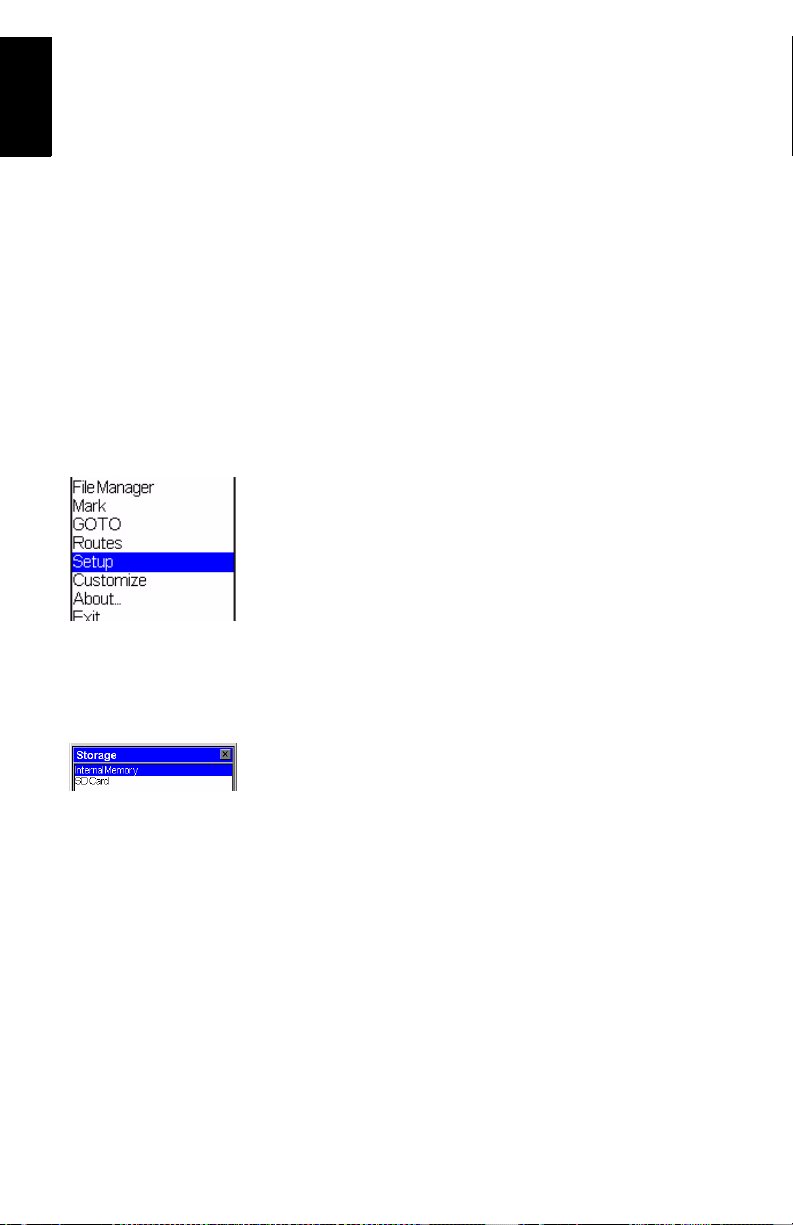
Access to Preliminary Settings
Now that ProMark3 displays a navigation screen, press the
MENU key and tap Setup (see screen opposite).
There are many options to select among, and all are explained
in full in the ProMark3 RTK / ProMark3 Reference Manual
available from the documentation CD. For the purposes of getting started, however, we will concentrate on just a few of
these options.
As a general rule, tap an option to open the corresponding setting window. Then tap the desired value. This will enable the
value and take you back to the Setup menu. You can also return to the Setup menu by pressing the ESC button.
Navigation Tools on page 69.
Choosing the Storage Medium
ProMark3 can store your jobs either in its internal memory or
on the SD card you have inserted in the unit. Tap the desired
option.
8
Page 15

Entering the Receiver ID
(From within Surveying function only)
The Receiver ID screen provides you with the ability to enter
the 4-character receiver ID which is used in naming the raw
data files. Each raw data file from this receiver will include
this 4-character receiver ID.
Specifying the Antenna Used
You select this option to define the type of external antenna
used, its height and the unit used to express this height.
Three different types of antennas are listed (ProMark Antenna
110454, NAP100 or Other). If you choose “Other”, you will
have to define the following parameters for your antenna: an
tenna radius, phase center offset and SHMP offset (slant
height measurement point offset).
Antenna Radius
SHMP
Phase Center
Offset
Offset
The choices made through the External Antenna option become the default antenna settings for all the ProMark3 surveying and mobile mapping functions.
English
-
Choosing the Units
You select this option to set the units of measurement you
want to use. Units are presented in this order: long distances,
short distances, speed and area. You can set these units to
“kilometers, meters, kph and hectares” or “miles, feet, mph,
acres” if you like, or to three other standard sets of units. You
can also create a custom mix of units by selecting the Ad
vanced option that contains a wide variety of units for distance, speed, elevation, bearing and area.
-
9
Page 16
English
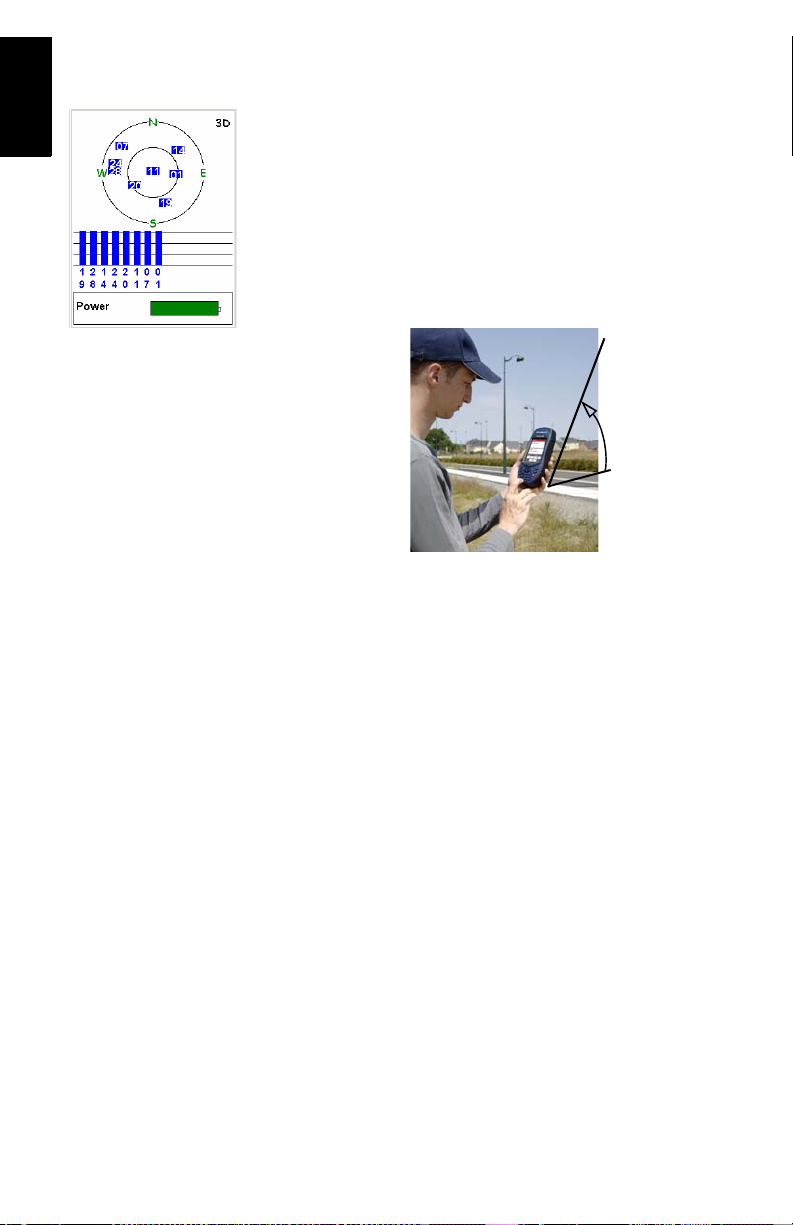
Checking that ProMark3 Receives Satellites
Press NAV repeatedly until the Satellite Status screen is displayed. This screen shows which satellites the receiver is
tracking and where they are located in the sky. If you are not
tracking 3 or more satellites you may have to move to a more
open area.
When used with its internal antenna (Mobile Mapping only),
the receiver will have the best view of the sky when you hold
it at an angle of 45 degrees from horizontal and not too close
to you.
Satellite Status screen
45°
This allows the internal antenna to function optimally for the
best accuracy.
In Survey jobs for which the external antenna is mandatory,
only the vertical orientation of this antenna is important.
10
Page 17
3. RTK Setup
When the base setup is
under your responsibility, make sure the base
is sited in a clear area
giving the best possible
view of the sky!
When this is possible,
avoid trees, buildings
or any high obstacles in
the vicinity of the base.
Having a clear view of
the sky will allow the
base to collect data
from a maximum of
visible satellites, which
is highly recommended
to perform a
successful, accurate
and fast survey.
Introduction to RTK
Enabling the RTK algorithm in the ProMark3 RTK is simply
done by launching “Surveying”, pressing MENU, selecting
Receiver Mode and then Real-Time or Real-Time & Raw Data
Recording.
From this time on, the ProMark3 RTK will operate to deliver
fixed position solutions, provided the operating requirements
are met.
Selecting Real-Time & Raw Data Recording is a safe way to
perform a real-time survey. With raw data recorded in the
background, you will have the capability to post-process the
raw data in the office. This however requires that base raw
data be also available for the same period of time (see also
page 39).
The table below summarizes the keywords and principles used
in the RTK technique. Please carefully read this table before
getting started.
1. Corrections. Corrections generated by a static receiver
(“base”) are needed for the rover to be able to deliver
centimeter-accurate positions.
2. Data Link. The data link that must be established to
transfer corrections from the base to the rover can be
implemented in three different ways with
ProMark3
RTK: license-free radio, cellular phone
(GPRS) or any other external RTCM device.
3. Base. Depending on the chosen data link, the base will
be either:
• A ProMark3 RTK set as a base and generating
RTCM3.1 corrections.
• Or an external provider delivering its corrections via
the Internet. In this case, corrections may be the
following: RTCM3 or RTCM2.3.
English
11
Page 18

English
4. ProMark3 RTK Configurations
Base
Radio Data Link
Base/Rover
(Base/rover System)
Rover
GPRS Data Link
Internet
Rover-Only
(Network Connection)
Rover
+ Cell
Phone
5. Rover Initialization. Before starting a survey, the rover
must be initialized. There are three possible methods:
“On The Fly”, “Known Point” and “Bar”. The “Bar”
method can only be used if you have your own base.
The initialization methods are introduced in the postprocessing chapter (see
page 42). The description is
accurate for real-time processing too. Unlike post-processing though, real-time processing tells you in real
time when initialization is complete.
Compared with post-processing surveying, RTK surveying proposes a fourth initialization method called “Stat-
ic”. With this method, the antenna should stay still over
an unknown point until initialization is achieved. This
method gives faster initialization than “On-The-Fly”
initialization in the same operating conditions.
The time required for initializing the rover ranges from
a few seconds to a few minutes, depending on the baseline length, the GPS constellation and the initialization
method used.
“Known Point” and “Bar” are the fastest initialization
methods.
6. Baseline Length. Whatever the base used, its distance
to the rover, called “baseline” (up to 1.6 km or 1.0 mile
with license-free radios, up to 10 km with a network
connection), must roughly be known to make sure RTK
positions will achieve the expected level of accuracy.
12
Page 19

Base/Rover Configuration
You are using your own ProMark3 RTK base to generate the
RTCM corrections needed by the rover. A pair of Magellan license-free, plug-and-play radios is used for the data link.
In the Base/Rover Configuration example described in this
guide:
- “Surveying” is used as the user interface.
- The base is installed on a known point. The coordinates
of this point were uploaded to ProMark3 RTK from a
GNSS Solutions project containing this point. This
means the point is now selectable from the list of control
points stored in the ProMark3 RTK.
NOTE: Points uploaded to ProMark3 RTK through this
method always have their coordinates automatically con
verted to WGS84.
- The “Bar” method is used to achieve rover initialization.
On the rover, a range pole fitted with a quick release
adaptor is required to use this method.
English
-
13
Page 20
English
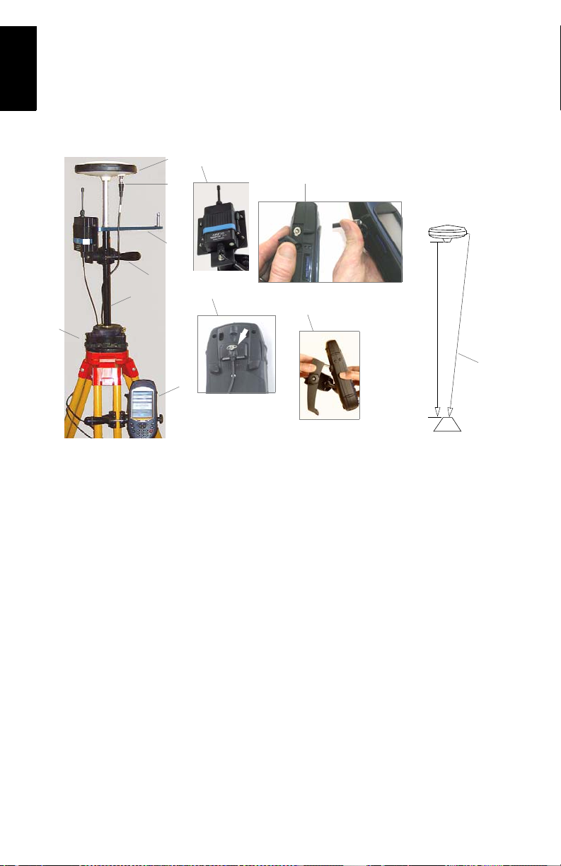
1.
Setting Up the Base
The installation site should offer the best possible GPS reception conditions. The antenna should have a clear view of the
sky in all directions. There should be no, or a minimum of satellite obstructions in the vicinity.
4.
5.
7.
3.
6.
2.
9.
10.
8.
H SlantH Vertical
5.
11.
12.
1. Set up the tripod / tribrach combination over the point.
2. Screw the RTK vertical antenna extension into the tribrach.
3. Insert the kinematic bar on top of the RTK vertical
antenna extension.
4. Attach the GNSS antenna on top of the kinematic bar.
5. Mount the license-free radio onto its bracket using the
screws, nuts and washers provided.
14
Page 21
The higher the radio, the
better the quality and
range of the radio link.
Warning!
Unscrewing the radio
antenna protection is
pointless or even hazard-
ous for the antenna.
6. Secure the radio bracket onto the RTK vertical antenna
extension. Place it as high as possible, just underneath
the GNSS antenna, as shown. Placing the radio too low
will reduce the radio range.
7. Connect the external antenna cable to the GNSS antenna.
8. Connect the other end of the external antenna cable to the
ProMark3 RTK. Lift the flap on the side on the unit to
access the antenna input connector.
9. Connect the radio cable to the back of the receiver. The
connection is secure after you have fully tightened the
thumb screw.
10.Place the ProMark3 RTK receiver into the field bracket.
11.Attach the field bracket / ProMark3 RTK combination
onto the tripod.
12.Measure and record the instrument height (HI) of the
GNSS antenna.
13.Turn on the ProMark3 RTK and check that the green LED
indicator on the radio is on. This means the connection
between the radio and the ProMark3 RTK is correct and
the radio is normally powered.
Configuring the Base
Remember in this example that the position of the base is
stored in the ProMark3 RTK as a control point (see
Follow the instructions below:
1. Double-tap the Surveying icon.
2. Press MENU, tap Receiver Mode, then Real-Time.
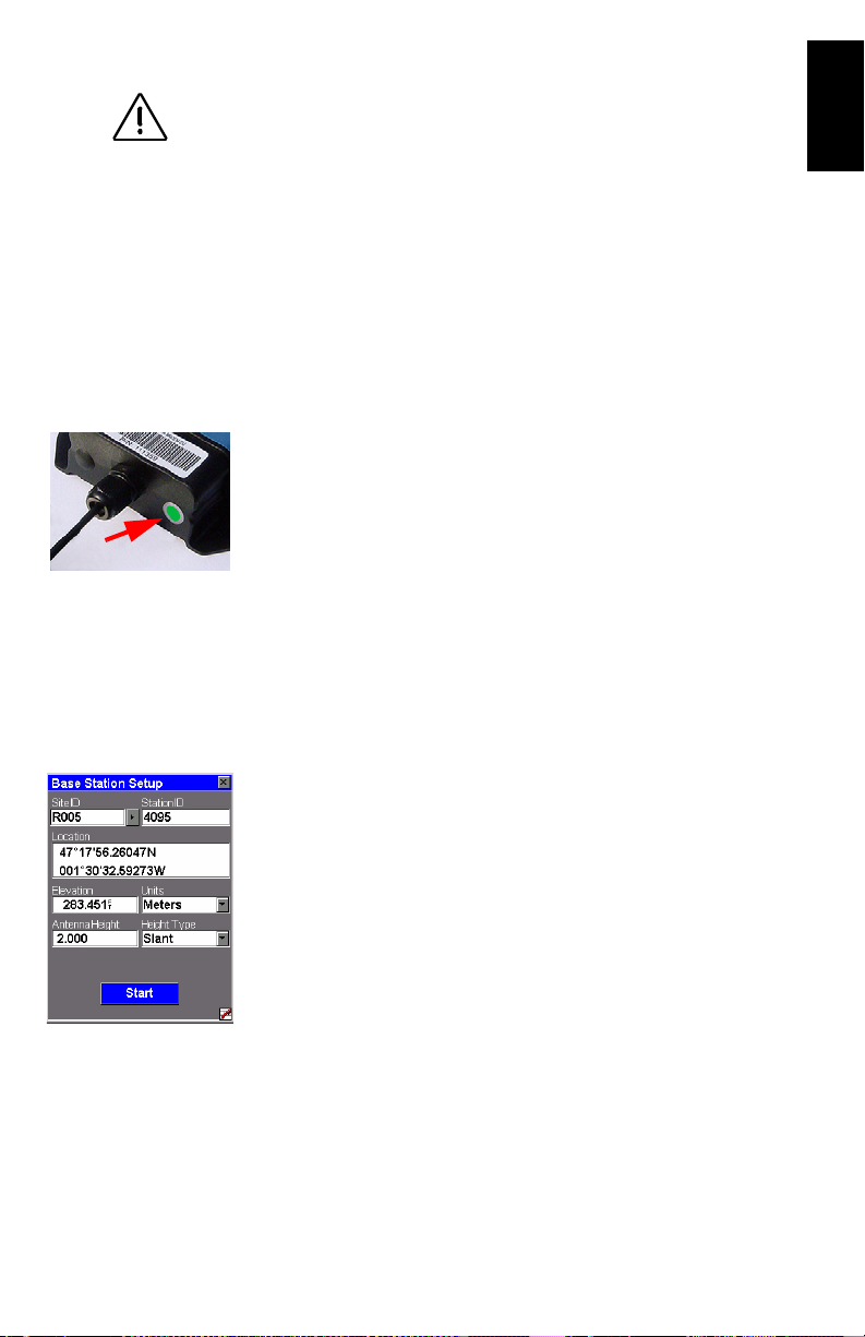
3. Press MENU, tap Base Station and enter the base parameters:
• Site ID: Allows you to quickly enter the coordinates of
the base: Tap the right-arrow button to the right of the
field.
page 13).
English
15
Page 22
English
This opens a points list from which you can select the
control point name corresponding to where the base is
installed. This automatically sets the Location field to
the right coordinates.
• Station ID: A 4-character string (0.. 4095).
• Location: Coordinates of base position. See Site ID field
above.
• Elevation: Above ellipsoid.
• Units: Antenna height unit (meters, US feet or Int
feet).
• Antenna Height: From the reference point.
• Height Type: Slant or Vertical.
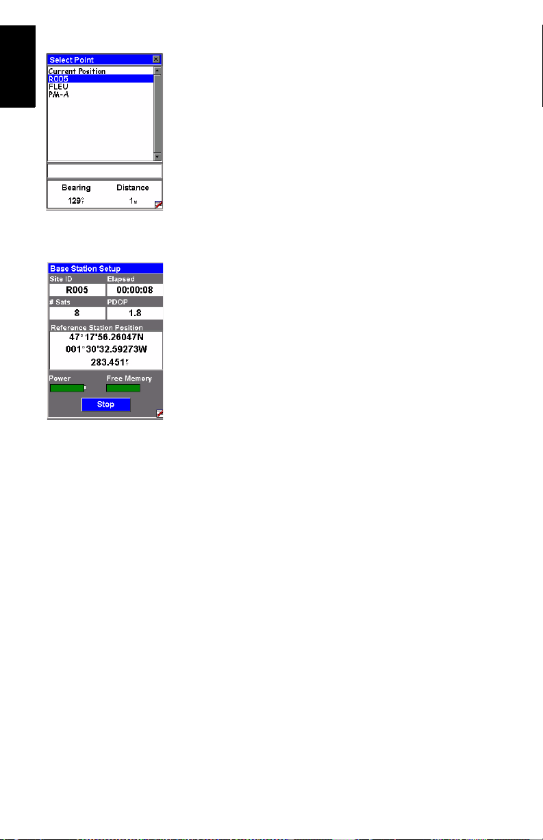
4. Tap Start. The ProMark3 RTK starts operating as a base.
RTCM 3.1 corrections are now broadcast via the radio
modem. The screen shows
• Site ID: As a reminder
• Elapsed: Time elapsed since you started the base sta-
tion
• # Sats: Current number of satellites received
• PDOP
• Base Station Position
• Power indicator (all green: fully charged)
• Free memory indicator (all green: maximum)
the following parameters:
16
Later, after you have finished your survey and you come back
to the base to switch it off, first tap Stop. The ProMark3 RTK
will instantly stop transmitting RTCM corrections.
Page 23
Setting Up the Rover
Install the unit on its range pole:
5
6
7
1. Mount the GNSS antenna on top of
the pole using a quick release exten
sion.
2. Mount the radio modem onto its
bracket using the screws, nuts and
washers provided.
3. Secure the radio bracket onto the
pole.
4. Connect the GNSS antenna to the
ProMark3 RTK using the cable provided.
5. Connect the radio cable to the back
of the ProMark3 RTK.
6. Attach the field bracket onto the pole
7. Place the ProMark3 RTK into the
field bracket
8. Measure the antenna height.
1
-
2-3
4
6-7
English
Configuring the Rover
1. Turn on the ProMark3 RTK.
2. Double-tap the DGPS Configuration icon. This opens the
DGPS Configuration window.
3. Tap Select Mode, select UHF and tap OK. Tap OK again to
close the DGPS Configuration window.
Initializing the Rover
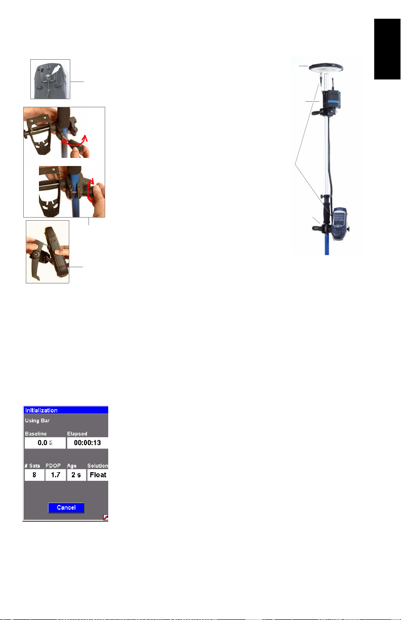
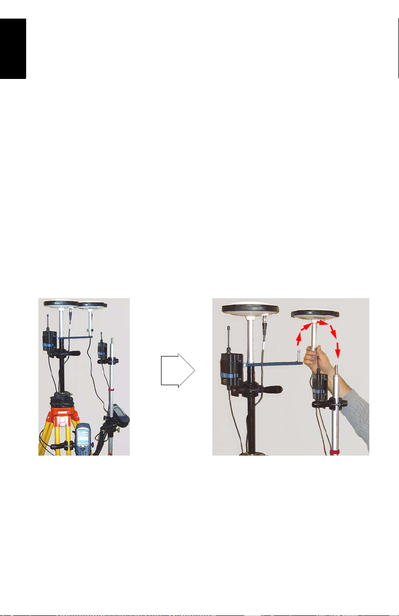
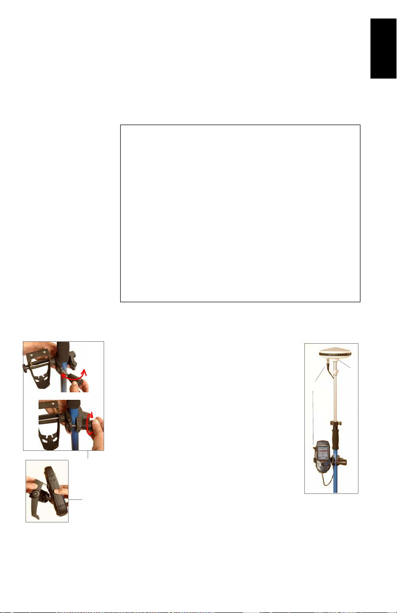
1. Move the rover antenna from the range pole to the kinematic bar (see picture below left), then:
2. On rover side, double-tap the Surveying icon.
3. Press MENU, tap Receiver Mode, then Real-Time.
4. Press MENU and tap Initialize RTK.
5. Select Bar. This opens the Initialization window.
17
Page 24
English
6. Keep an eye on the displayed parameters while the
receiver initializes:
• Baseline: Baseline length. Should stay 0.0 km in the
case of a bar initialization.
• Elapsed: Counts the time since you started initializa-
tion.
• # Sats: Should be 6 or more for fast initialization.
• PDOP: Should be less than 3.
• Age: Should stay around 2 seconds. If it starts increas-
ing steadily, this probably means RTCM corrections are
no longer received. Check your radios.
• Solution: Position solution status. Should be a blinking
“Float” throughout initialization.
When “Fixed” appears in the Solution field, this means
the rover is initialized. A new button (OK) then appears
next to the Cancel button.
7. Tap OK to close the Initialization window.
8. Move the rover antenna from the initializer bar to the top
of the rover pole (see picture below right). While doing
this, take care not to mask the rover antenna or else you
would have to resume initialization.
18
9. Refer to Standard RTK: “Surveying” on page 24 to start
your survey.
Page 25
Rover-Only Configuration (Network)
Two types of connections are possible: NTRIP and Direct IP.
Both rely on the use of a Bluetooth-enabled, GPRS-enabled
cell phone within range of the ProMark3 RTK.
No user-owned base needs to be deployed in this configuration.
In the Rover-Only Configuration example described in this
guide:
- “Surveying” is used as the user interface.
- The NTRIP mode is used to acquire RTCM corrections
from the Internet.
- The “Known Point” method is used to achieve rover initialization. The coordinates of the known point were
uploaded to ProMark3 RTK from a GNSS Solutions
project containing this point. This means the point is
now selectable from the list of control points stored in
the ProMark3 RTK.
NOTE: Points uploaded to ProMark3 RTK through this
method always have their coordinates automatically converted to WGS84.
Setting Up the Rover
Install the unit on its range pole:
1. Mount the GNSS antenna on the pole
2. Attach the field bracket onto the pole
3. Place the ProMark3 receiver into the field
bracket
4. Connect the GNSS antenna to the unit
using the cable provided.
5. Measure the antenna height.
4.
English
1.
2.
3.
19
Page 26

English
For step 5, you need to
know how to activate
Bluetooth on your cell
phone and how to make it
Please refer to its Instruc-
tions Manual.
Your cell phone may also
ask you for a paired con-
nection with the ProMark3
RTK. Please accept to be
able to proceed.
discoverable.
Configuring the Rover
1. Turn on the ProMark3 RTK.
2. Double-tap the DGPS Configuration icon.
3. Tap the Select Mode button.
4. For our example, select NTRIP and then tap OK. This gives
access to the NTRIP settings window from which you can
now do the following:
a) Establish a Bluetooth connection with your cell phone.
b) Establish an Internet connection via the cell phone.
c) Gain access to the NTRIP provider via the cell phone
and download the provider’s NTRIP source table.
5. To establish a wireless connection between the cell phone
and the ProMark3 RTK:
• Tap on the NTRIP Settings window.
• Turn on your cell phone. Activate its Bluetooth device. Make
its local Bluetooth device discoverable from external Bluetooth devices.
• On ProMark3 RTK, tap to search for the Bluetooth
devices present in the vicinity. At the end of the search
sequence, an icon representing your cell phone should be visible in the Bluetooth Manager window.
• Double-tap the cell phone icon. The Bluetooth Manager window now shows the Bluetooth services offered by your cell
phone.
• Double-tap the Dial-Up Networking icon. As a result, a connection is automatically implemented using the first Bluetooth virtual port available on ProMark3 RTK. The message
“Connection succeeded on communication port COMx:” is
displayed.
•Tap OK to close the message window. Note the presence of a
plug in a green circle on the Dial-Up Networking icon showing
that the connection is effective.
20
• Tap to close the Bluetooth Manager window. The NTRIP
Settings window now shows the Bluetooth connection to your
cell phone.
Page 27

For step 6, you need to
know the GPRS call num-
ber as well as your GPRS
connection profile (user
name, password, domain).
Please ask your phone
operator and/or GPRS pro-
vider if you don’t know
these parameters.
6. To establish a GPRS connection to the Internet via the cell
phone:
• Tap on the NTRIP Settings window.
• In the window that opens, double-tap the Make New Connec-
tion icon.
• Name the new connection (for example “My Cell Phone”)
using the virtual keyboard, keep Dial-Up Connection checked
on and then tap Next>.
•In the Select a modem field, select the port used on
ProMark3 RTK (i.e. the port assigned previously) to communicate with the Bluetooth modem of the cell phone (the
selected modem should be in the form “BT Modem on
<Cell_Phone_Name> COMx”)
• In the Modem window, tap Next>.
•In the Phone Number field, type the GPRS call number corresponding to your cell phone model and GPRS operator.
•Tap Finish. A new icon appears in the Connection window.
• Double-tap the icon you have just created in the connection
window.
• Enter the following parameters:
-User Name
- Password
-Domain
• Enable the Save password option.
• Tap on the Dial Properties button and then on the Edit but-
ton. This opens the Edit Dialing Patterns window.
• Correct the content of this window in order to read “G” in the
three fields.
•Tap OK twice to return to the Dial-up Connection window.
• Tap on the Connect button. The following messages appear
successively: “Opening Port”, “Dialing...”,... “User Authenticated” and “Connected”. The GPRS connection is now established.
•Tap Hide to close the message window.
English
• Tap to close the Connection window. The NTRIP Settings
window now shows the connection to the GPRS operator.
21
Page 28

English
7. To choose a station from which to receive RTCM corrections:
For step 7, you need to
know your NTRIP connec-
tion profile (host, port,
login, password).
Please contact your
NTRIP provider if you
don’t know these parame-
ters.
• Tap on the NTRIP Settings window. The NtripCaster Connection window opens in which you can store several NTRIP
configurations.
• To enter your first NTRIP configuration, with New selected in
the NTRIP Configuration field, tap on the Add button and
then enter the following parameters:
- Name: NTRIP Configuration Name (freely choose a name)
- Host: Host IP address
- Port: Port number
- Login: User name
- Password: User password
•Tap OK. The name of the configuration you have just created
is now pre-selected in the NTRIP Configuration field. Tap OK
again. This takes you back to the NTRIP Settings window (see
example opposite).
• Set the Network and Station fields to select the base to work
with.
•Tap OK. This takes you back to the DGPS Configuration win-
dow. On top of the screen, you can read part of the settings
you have just made.
• Tap the Connect button. The DGPS Configuration screen now
indicates the amount of incoming data packets (bottom of the
screen) as well as the status of the DGPS mode (top of the
screen).
•Tap OK to close the DGPS Configuration window. The follow-
ing two messages are displayed successively: “
and “
Processing incoming data packets...”.
•Tap OK to close the message window.
Please wait...”
22
Page 29

Initializing the Rover
Remember in this example that the position of the point used
for initializing the system is stored in the ProMark3 RTK as a
control point (see page 19). Follow the instructions below:
1. Hold the pole in vertical position over the known point.
2. Double-tap the Surveying icon.
3. Press MENU, tap Receiver Mode, then Real-Time.
4. Press MENU and tap Initialize RTK.
5. Tap Known Point.
6. Tap the name of the known point from the displayed list.
This opens the Initialization window.
7. Keep an eye on the displayed parameters while the
receiver initializes:
• Baseline: Baseline length.
• Elapsed: Counts the time since you started initializa-
tion.
• # Sats: Should be 6 or more for fast initialization.
• PDOP: Should be less than 3.
• Age: Should stay around 2 seconds. If it starts increas-
ing steadily, this probably means RTCM corrections are
no longer received. Check your connection to the cor
rections provider.
• Solution: Position solution status. Should be a blinking
“Float” throughout initialization.
When “Fixed” appears in the Solution field, this means
the rover is initialized. A new button (OK) then appears
next to the Cancel button.
English
-
8. Tap OK to close the Initialization window.
9. Refer to Standard RTK: “Surveying” on page 24 to start
your survey.
23
Page 30

English
4. Standard RTK: “Surveying”
It is assumed that RTK has been implemented according to
the instructions provided in chapter RTK Setup on page 11.
Once the rover has been initialized (see page 17 or page 23,
depending on whether you are in base/rover or rover-only configuration), you can move on to the survey as such. Always
take care to maintain maximum satellite visibility from the antenna in order to preserve system initialization.
If the rover loses initialization, you will need to resume this
step using whichever initialization method is preferable in
your context of use (see
Logging Points in Real Time
1. Walk to the first point you want to log and stand still on
that point.
2. Press the LOG key and then enter the following parameters:
• Site ID: A 4-character string.
• Survey Mode: Logging Point.
• Site Description: An optional 20-character narrative
description of the point. Tap inside the field, enter
your text from the on-screen keypad and press ENTER.
• Antenna Height: From the reference point.
• Units: Antenna height unit (meters, US feet or Int
feet).
• Height Type: Slant or Vertical.
• Time on site (sec): Time, in seconds, that must elapse,
with the antenna not moving, before the rover stores
the position of the point (default: 15 seconds). You
decide the duration of the occupation (If it is greater
second, the position solutions will be averaged
than 1
over this period of time to improve accuracy. If it is
second, there is no position averaging but work
1
proceeds more quickly).
page 12).
24
Page 31

3. Tap the OK button. This opens a new screen on which you
can see the following parameters:
• The name of the opened log file is shown in the title
bar between brackets.
• Baseline: Baseline length in km
• Solution: Solution status. Check that it is “Fixed” for
centimeter accuracy.
• Receiver status:
SV: Number of received SVs. Should be 6 or more.
PDOP: Should be less than 3.
Age: Age of corrections (should not be greater than
2 sec).
HRMS and VRMS: Should be in the order of
0.03 meters (1.2 inches) when the position is
fixed. Always displayed in meters whatever the chosen distance unit.
• Your position’s current coordinates, as determined by
the system.
4. If you are satisfied with the quality of the displayed data,
tap the on-screen LOG button. This opens a new screen on
which you can now see the Remain field count down. When
Remain=00:00:00, the STORE button appears at the bottom of the screen (see screen below right).
English
If the point you save has a
“Fixed” solution, then it is
stored as a control point.
This means it can later be
selected from the list of
control points to initialize
the system with the rover
precisely located over this
point.
5. Tap the STORE button. This saves the point position and
takes you back to the Logging Point screen where you can
see that the
Site ID has automatically been incremented by
one.
25
Page 32

English
6. Move to the next point you want to log.
7. Resume steps 3 through 6 as many times as necessary.
8. When all points have been logged, tap DONE on the
screen. This closes the open log file, which now contains
the positions of all the logged points, and takes you back
to the last displayed navigation screen.
Logging Trajectories in Real Time
1. Walk to the start point of the trajectory and stand still on
that point.
2. Press the LOG key and then enter the following parameters:
• Site ID: A 4-character string.
• Survey Mode: Kinematic.
• Site Description: An optional 20-character narrative
description of the point. Tap inside the field, enter
your text from the on-screen keypad and press ENTER.
• Antenna Height: From the reference point.
• Units: Antenna height unit (meters, US feet or Int feet)
• Height Type: Slant or Vertical.
• Interval Type: Time or Distance, according to whether you
want the points of the trajectory to be created and
logged at regular intervals of time or distance.
• Interval: Time elapsed, in seconds, or distance traveled,
in meters, between any two point positions logged
along the trajectory followed.
26
Page 33

3. Tap the OK button. This opens a new screen on which you
can see the following parameters:
• The name of the opened log file is shown in the title
bar between brackets.
• Baseline: Baseline length
• Solution: Solution status. Check that is “Fixed” (for
centimeter accuracy).
• Receiver status:
SV: Number of received SVs. Should be 6 or more.
PDOP: Should be less than 3.
Age: Age of corrections (should not be greater than
2 sec).
HRMS and VRMS: Should be in the order of
0.03 meters (1.2 inches) when the position is
fixed. Always displayed in meters whatever the chosen distance unit.
• Your position’s current coordinates, as determined by
the system.
4. Tap the START button to start logging the trajectory.
5. Walk along the trajectory and let the system operate on its
own. You can see that the
mented as you walk. Note that using the PAUSE button,
you can pause the position logging if you need to do so.
6. When you have reached the end of the trajectory, tap the
DONE button. This closes the open log file, which now
contains the positions of all the logged points along the
trajectory, and takes you back to the last displayed navigation screen.
Site ID is automatically incre-
English
27
Page 34

English
Staking Out
1. Press the LOG key and then enter the following parameters:
• Survey Mode: Stakeout.
• Antenna Height: From the reference point.
• Units: Antenna height unit (meters, US feet or Int
feet).
• Height Type: Slant or Vertical.
• Time on site (sec): Time, in seconds, that must elapse,
with the antenna not moving, before the rover stores
the position of the point (default: 15 seconds). You
decide the duration of the occupation (If it is greater
second, the position solutions will be averaged
than 1
over this period of time to improve accuracy. If it is
second, there is no position averaging but work pro-
1
ceeds more quickly).
• Enter coordinates manually check button: Do not check
this button if the points you want to stake out are control points already stored in memory. Check it on if you
want to enter the coordinates for a point to stake out.
2. Tap the OK button. Depending on how you set the Enter
coordinates manually check button, the receiver now displays the list of control points, so you can select one
(below left), or asks you to enter the coordinates of the
point to stake out (below right). In the latter case, make
sure the coordinate system used is the right one (MENU
key> Setup> Coord Sys).
28
Page 35

3. After you have selected a point from the list or entered
coordinates manually, the ProMark3 RTK switches to the
last selected navigation screen.
4. Follow the instructions on the screen to get closer to the
stakeout point. When the distance to the point is only
about one meter, the screen displays the following:
East
Distance
0, 0
Target Point
North
Distance
English
N
E
5. Check the distances displayed at the top of the screen.
Move the pole to zero these values (see diagram above
left). Carefully plumb the pole for precise staking. The displayed distances should be interpreted as follows:
• East 0.233 M means you must move east to zero this
value.
• North 0.367 M means you must move north to zero
this value.
6. When these values are all zero, stop moving. You are on
the point.
7. Set the stake.
8. You may want to take another reading to save the asstaked position. Obviously, this position should be the
same as that of the stakeout point but later you can compare your field work with the target coordinates.
29
Page 36

English
To save the as-staked position:
• Tap the OK button. This opens a new screen on which
you can now see the Remain field count down. In the
window’s title bar is the name of the log file where the
position is about to be saved. Note that a non-editable
Site ID, different from the name of the target point, is
automatically assigned to that position. GNSS Solu
tions will automatically make the correspondence
between the target point and the saved position.
When Remain=00:00:00, the STORE button appears at
the bottom of the screen (see screen below right).
• Tap the STORE button. This saves the point position
and takes you back to the stakeout screen.
9. Tap Next to display the list of control points from which
you can select a new target point.
10.Resume steps 4 through 7 until all the points have been
staked out, then tap
takes you back to the last displayed navigation screen.
If you have also logged the positions where you placed
your stakes, tapping Done also closes the log file containing the measured positions of all these points.
Done to end the stake out survey. This
-
30
Quitting The Surveying Function
Press the MENU key and tap Exit. This takes you back to the
ProMark3 RTK workspace.
Page 37

5. Advanced RTK: FAST Survey Option
Introduction
The two requirements for running FAST Survey are: 1) You are
using a ProMark3 RTK and 2) FAST Survey has been unlocked.
Launching FAST Survey
From the ProMark3 RTK workspace, double-tap the FAST Sur-
vey icon to launch FAST Survey. The software takes full control
of the platform and re-assigns new functions to the function
keys. See re-allocation table on
Creating a New Job
FAST Survey first asks you to open a job (a crd file). Do the
following:
1. Choose Select New/Existing Job. A new screen is now dis-
played.
2. In the Name field, type in the name of the job you wish to
create. For example, type in “tuto1.crd”.
3. Then tap OK to create the job. The screen then displays
the Units tab.
4. On the Units tab, set the desired units and parameters for
the job.
5. Tap on the GPS tab.
On the GPS tab, choose the coordinate system to be used
in the job as well as the geoid model. A large number of
coordinate systems are stored in FAST Survey. To select
one of them, click on the Edit Projection List button and
then Add Predefined. Some coordinate systems require that
a datum grid (or projection grid) be uploaded before you
are allowed to use them. Geoids can be uploaded using
GNSS Solutions.
6. After selecting all the desired parameters, click OK
(located on top of the screen).
page 72.
English
31
Page 38

English
Configuring a Base
It is assumed that the ProMark3 RTK base has been set up as
explained in RTK Setup on page 11. If you want to use the Bar
method to initialize the rover, don’t forget the kinematic bar
between the antenna and the tribrach.
1. Tap on the Equip tab.
2. Tap the on the Instrument button.
3. Select ProMark3 Magellan Base and tap OK.
4. Tap on the Configure Base button, define the antenna
height and type as well as the elevation mask.
If you intend to log base raw data, check on the Data
Recording option, set the recording interval in seconds,
define the media where to store the data (SD Card or
Internal memory) and enter a Unit ID. Reminder: This
parameter is used as header in raw data filenames.
5. Tap OK to enter all these settings. FAST Survey then asks
you to enter the position of the base and then the reference station ID.
6. When base configuration is complete, FAST Survey asks
you to save the base settings in a ref file (<job_name.ref).
The ProMark3 RTK will then run as a base until you exit
FAST Survey.
32
Configuring a Rover
It is assumed that the ProMark3 RTK rover has been set up as
explained in RTK Setup on page 11.
1. Tap on the Equip tab.
2. Tap the on the Instrument button.
3. Select ProMark3 Magellan Rover and tap OK.
4. Tap on the Rover Settings button, define the antenna
height and type as well as the elevation mask. Indicate the
type of position solution that is expected from the rover
(“Float” or “Fixed” status).
Page 39

If you intend to log rover raw data, check on the Data
Recording option, set the recording interval in seconds,
define the media where to store the data (SD Card or
Internal memory) and enter a Unit ID. Reminder: This
parameter is used as the header in raw data filenames.
5. Tap OK to enter all these settings and complete the rover
configuration.
Initializing the Rover
1. Tap on the RTK Initialization button (Equip tab)
2. Select the type of initialization you wish to use (see opposite) and then follow the instructions on the screen.
NOTE: Except for “On The Fly Initialization”, the message
“Please do not move the antenna until the position is Fixed!”
will appear when you choose an initialization method. Tap
OK to close this message window.
3. After you have selected an initialization method, FAST
Survey will switch to the Monitor/Skyplot screen. This
screen shows the progress of the initialization phase
(HRMS, VRMS, Status, Latency, etc.).
4. A beep can be heard when the position solution is fixed.
You can then tap BACK at the top of the screen and move
on to your survey, taking care not to lose system initializa
tion.
English
-
33
Page 40

English
Logging RTK Points
1. Tap on the Surv tab and then on Store Points. The screen
Logging point
with offset
Logging point
(general case)
Current status of
position solution
Enter the point name and
description in these two fields
Current position and related
quality figures
now displayed allows you to log all your points.
The figure below summarizes all the functions available
from that screen.
Logging point with
position averaging
Configures general
case of point logging
Provides access to
monitor screen
Your current position
and heading
Graphic Display area
GNSS antenna height
Zoom settings
Viewing parameters
For example, you are on a point that you want to log. Do
the following:
2. Type in the point name and description in the corresponding two fields (see above)
3. Tap on the “A” button
4. Enter the number of readings you want before FAST Survey is allowed to compute an average position for this
point. For example, type in “5” and tap
OK.
Messages follow successively indicating that the system is
taking the 5 requested readings. Then FAST Survey displays the average coordinates it has determined.
5. Tap OK if you agree. The “Point Stored” message appears
briefly. The screen then shows the location of the point
together with its name and description.
34
Page 41

6. After logging all your points, tap MENU in the upper-right
corner of the screen to return to the menu.
Logging RTK Points in Continuous Mode
1. On the Surv tab, select the Auto by Interval function. Two
different modes are possible: Time or Distance.
2. If you choose Distance, enter the horizontal and vertical
increment value respectively in the
according to the chosen unit. If you choose Time, enter the
increment value, in seconds.
3. Enter a point Id. for the start point in the Starting Pt ID
field. This field will be incremented by one after each
point logging. You do not need to define a name finishing
with a figure. FAST Survey will place one anyway when
incrementing this field.
4. Press OK to switch to the graphic screen (see figure below)
and start logging the first point.
Used to log a point’s
position manually
Point Id.
incremented
automatically
X/Y and Z fields,
Used to pause/resume
data logging
English
The S button lets you instantly log the position of a point.
The X button allows you to pause data logging in continuous mode.
If data logging in continuous mode is paused, you can still
continue to log points in manual mode using the S button.
35
Page 42

English
Name of point to
be staked out
Coordinates of point
to be staked out
Tap the X button again (changed into a right arrow during
pause) to resume data logging in continuous mode.
If you come back to the main menu by tapping on MENU,
then data logging in continuous mode is automatically
stopped.
Staking out RTK Points
1. Tap on the Surv tab and then select Stakeout Points. The
screen now displayed allows you to stake out your points.
2. On this screen, FAST Survey asks you to choose the point
you want to stake out. You can either type in its coordinates in the Northing, Easting and Elevation fields, or select
a pre-defined point from the points list (see File>List
Points). You can also, define graphically this point by tapping on the point on the graphic screen, or define that
point according to azimuth, slope and horizontal distance.
Provides access to points list.
Example of points list:
Provides access to
graphic screen
36
Page 43

3. Once you have chosen a point, tapping on the OK button
Stakeout screen
Next point
Logs the point
Provides access to the detailed
stakeout screen below
Detailed stakeout screen
Point to be staked out
will display a graphic screen from which you can easily
stake out your point:
Takes you back to the point
selection screen
Configures general
case of point logging
Provides access to
monitor screen
Point to be staked out (target)
Your current position and
heading
English
Your current position
and heading
4. Tapping on the STORE button allows you to start perform-
Used to select which guidance
data to display
Used to select which data to
display for the point:
coordinates or quality data
The target radius is automatically changed as the distance
from you to the point changes.
When getting closer to the point, markers appear at the
four corners of the target (see below left) informing you
that you nearly are on the point. You can now set the stake
and log the position of this point.
ing measurements to determine the position of the point.
37
Page 44

English
The number of measurements will depend on the value
entered earlier through the File tab>Configure Readings
function. Once the position has been determined, FAST
Survey displays the results of the computation so that you
can check them (see below right).
5. Tap OK if you are satisfied with the results. FAST Survey
will then save these results and will take you back to the
stakeout screen for the next point.
38
Page 45

6. Post-Processing Surveying
Make sure the base is sited
in a clear area giving the
best possible view of the
Having a clear view of the
mended to perform a suc-
cessful, accurate and fast
sky!
When this is possible,
avoid trees, buildings or
any high obstacles in the
vicinity of the base.
sky will allow the base to
collect data from a maximum of visible satellites,
which is highly recom-
survey.
Reminder on Surveying Techniques
Static
Typical Use: Surveying a New Control Point.
Base
Equipment Involved Field Organization
Baseline
(Range)
Observation time
Time Organization
Data collected at base:
Data collected on surveyed point:
Key Instructions:
Two units needed: one (the base) operated on an accurately known
1.
position and the other (the rover) on the point to be surveyed. There
can be several rovers logging data at the same time.
Approximate distance between the two units (baseline) must be
2.
known.
Data must be collected simultaneously by the two units. Use the
3.
same logging interval on both units.
Observation time is determined by last unit set up (start) and first unit
4.
turned off (end). We recommend that you start the base first and you
turn it off last.
Required observation time mainly depends on distance between the
5.
two units (+ reception conditions). Rover unit estimates observation
time needed.
When Obs. Range on screen is equal to or greater than the baseline,
you can stop collecting data.
Known Point Survey Point
English
Rover
39
Page 46

English
“Stop & Go”
Typical Use: Surveying Several Points within a Relatively
Small Area.
Make sure the base is sited
in a clear area giving the
best possible view of the
Having a clear view of the
mended to perform a suc-
sky!
When this is possible,
avoid trees, buildings or
any high obstacles in the
vicinity of the base.
sky will allow the base to
collect data from a maximum of visible satellites,
which is highly recom-
cessful and accurate
survey.
Equipment
Field Execution
Time Organization
Data collected at base:
Data collected by rover:
Key Instructions:
Two units needed: one stationary (the bas e) and the other (the rover)
1.
moved successively on the points to be surveyed. There can be several
rovers logging data at the same time.
Survey must start with an initialization phase (see page 42).
2.
Once initialization is achieved, be careful not to mask the rover’s
3.
GNSS antenna throughout the survey. In case of satellite signal
loss, you will have to resume the initializ a tion phase.
Data must be collected simultaneously by the two units. We recommend
4.
that you start the base first and you turn it off last. Use the same logging interval on both units. Rover collects data continuously
throughout the survey .
User-preset occupation (observation time) on each surveyed point.
5.
Defaults: 5 min. on init point, 15 sec. on surveyed points. Countdown
tells the user when he/she can move to the next point.
0002
Rover
Rover
0004
00050006
Base
Known Point Survey Point
0001
Base
Init Point
See page 42
0007
5 min. with bar
0001 0002 0003 0004 0005 0006 0007
Init
Occupation: 15 sec. typical
0003
40
Page 47

Kinematic
Typical Use: Surveying Trajectories.
English
Make sure the base is sited
in a clear area giving the
best possible view of the
Having a clear view of the
mended to perform a suc-
sky!
When this is possible,
avoid trees, buildings or
any high obstacles in the
vicinity of the base.
sky will allow the base to
collect data from a maximum of visible satellites,
which is highly recom-
cessful and accurate
survey.
Equipment
Field Execution
Time Organization
Data collected at base:
Data collected by rover:
Key Instructions:
Two units needed: one stationary (the base) and the other (the rover)
1.
moved along each surveyed trajectory. There can be several rovers
logging data at the same time.
Survey must be preceded by an initialization phase (see page 42).
2.
Once initialization is achieved, be car eful no t to mask the r ove r’s
3.
GNSS antenna throughout the survey. In case of satellite signal
loss, you will have to resume the initialization phase.
Data must be collected simultaneously by the two units. We recom-
4.
mend that you start the base first and you turn it off las t. Use the
same logging interval on both units. Rover collects data continu-
ously throughout the survey.
Site ID is automatically incremented along the traj ectory according to
5.
the recording interval used.
Base
Known Point Survey Point
0001...
Log
Base
Done
5 min. with bar
0001...
Init
Init Point
See page 42
0015...
Rover
Rover
0015...
Pause
Log
41
Page 48

English
The initialization phase is
required to ensure that
your kinematic surveys,
whether continuous or Stop
& Go, will reach centime-
ter-level accuracies through
With the “Known” method,
you can make a survey at a
fairly long distance from
Conversely, with the “Bar”
method (the method we
recommend), your survey
will necessarily start from
the base and obviously the
points to be surveyed
should not be too far away
post-processing.
the base.
from the base.
Initialization Methods
Three possible methods, from fastest to slowest:
• Known: Initialization on Known point.
Initialization achieved
in 15 seconds
Init point can be several kilometers away from the base.
Known Point
You need to specify the Site ID of the known point (surveyed in a previ-
1.
ous job or downloaded from office software).
GNSS antenna held stationary over known point for about 15 seconds
2
Countdown indicates when initialization is achieved.
3.
• Bar: On Initializer Bar Installed at the Base
Initialization
achieved
in 5 minutes
Init point is 20 cm
off the base location.
Initializing...
1
T
h
i
s
v
Base
Known Point
e
c
t
o
r
i
s
a
c
c
u
r
a
t
e
l
y
k
n
o
w
n
Move antenna to range pole
2
once countdown complete.
RoverBase
Init point is a known
point
Rover
With the “<None>”
method, the survey start
point can be any point but
you should have a rough
idea of the distance from
your working area to the
base so you can estimate
the overall time you should
spend collecting data (15
to 30 minutes typical)
42
You freely enter a Site ID for the rover’s start point
1.
GNSS antenna held stationary on the initializer bar for about 5 minutes.
2.
Countdown indicates when initialization is achieved.
3.
Move the antenna from the bar to the range pole taking care not to
4.
mask the antenna while doing this. Then start your job
• <None>: On The Fly (OTF) Initialization
No initialization point
Known Point
D
You freely enter a Site ID for the rover’s start point
1.
There is no countdown indicating when initialization is achieved.
2.
RoverBase
Rover’s start point is
an unknown point
Page 49

Running a Static Survey
Typical setup with tripod is
described here.
You can also use a fixed-
height tripod.
4.
Equipment Setup
The equipment setup instructions are the same for both the
base and the rover. Install and run the base first.
In both cases, the installation site should offer the best possible GPS reception conditions. The antenna should have a
clear view of the sky in all directions. There should be no, or
a minimum of satellite obstructions in the vicinity.
1. Set up the tripod / tribrach combination over the point.
2. Attach the vertical extension bar and a tribrach adapter to
the GNSS antenna.
3. Place the GNSS antenna assembly on the tripod.
4. Place the ProMark3 receiver into the field bracket.
5. Attach the field bracket / ProMark3 combination onto the
tripod.
6. Connect the GNSS antenna cable to the unit.
7. Measure and record the instrument height (HI) of the
GNSS antenna.
2.
6.
3.
5.
7.
H SlantH Vertical
English
1.
43
Page 50

English
Satellite Status screen
Static Survey Setup
It is assumed that you have already run all the instructions detailed in Chapter 2. Preparing For First-Time Use on page 4.
Follow the instructions below to run both the base and the rover.
1. Turn on the receiver by pressing the red key.
2. Double-tap the Surveying icon.
3. If you have a ProMark3 RTK, press MENU, tap Receiver
Mode and then Post-processing.
4. Press the NAV key until you see the Satellite Status screen
(see opposite). Wait until at least 4 satellites are received.
5. When there is enough satellites received, press the LOG
key. The
Survey Settings screen opens.
44
6. Enter the following parameters:
• Site ID: A 4-character string.
• Survey Mode: Static.
• Site Description: An optional 20-character narrative
description of the point.
• Antenna Height: From the reference point.
Page 51

• Units: Antenna height unit (meters, US feet or Int feet)
• Height Type: Slant or Vertical.
VerticalSlant
• Recording Interval: Time in seconds between any two
consecutive acquisitions of GPS data. Make sure the
same recording interval is used at the base and in the
rover.
• Control Point check box: If you check this box, you will
be able, later on, to use the point associated with this
Site ID as a control point.
English
Data Collection
7. Tap the Log button at the bottom of the screen.
The Static Survey screen opens providing information on
the status of your survey during the data collection period.
Information provided here will help you determine when
enough data has been collected.
45
Page 52

English
Make sure the rover
antenna will have the best
possible view of the sky at
all times during the sur-
vey. This should result in
#Sats continuously greater
than 4 and PDOP continu-
ously less than 4.
Obs. Range is equivalent to
Obs. Timer in ProMark2.
8. Watch the following data on the rover unit:
• Obs. Range (Observation Range): Indicates the maxi-
mum length of the baseline that could be accurately
determined through post-processing considering the
amount of data currently collected. The more you col
lect data, the longer this baseline.
• Elapsed: Time elapsed since data collection began.
• # Sats: Number of received satellites.
• PDOP: Current PDOP value.
9. When according to the Obs. Range parameter on the rover,
enough data has been collected in this observation ses
-
sion, tap the Done button at the bottom of the screen or
press the ENTER key.
10.Follow the steps presented above for each observation
session required to complete your survey. After data col
lection is complete, take all ProMark3 receivers used in
the survey to the office and download the data to an office
computer as described in
Downloading Raw Data on
page 62. The data is now ready for post-processing using
GNSS Solutions.
Running a “Stop & Go” Survey
This chapter describes a typical Stop & Go survey in which initialization is performed using the initializer bar. (This is the
initialization method recommended by Magellan.)
It is assumed that you have already run all the instructions detailed in Chapter 2. Preparing For First-Time Use on page 4.
-
46
Page 53

Allowing for kinematic ini-
tialization using Initializer
bar at the base
1.
Base Setup and Operation
The base is setup and operated in the same way as it is in static surveys (see page 43). The only difference is the use of the
initializer bar at the base station.
The base antenna should be centered and levelled above the
known point. To be able to use the initializer bar for initialization, be sure to incorporate the bar as part of the base setup
as shown opposite.
Rover Setup
Install the unit on its range pole:
1. Attach the field bracket onto the pole.
2. Place the ProMark3 receiver into the field
bracket.
3. Connect the GNSS antenna cable to the unit.
4. Mount the GNSS antenna at the end of the
base’s initializer bar.
5. Connect the other end of the antenna cable to
the rover antenna.
2.
4.
5.
3.
English
47
Page 54

English
Satellite Status screen
VerticalSlant
Stop & Go Survey Rover Setup
1. Turn on the receiver by pressing the red key.
2. Double-tap the Surveying icon.
3. If you have a ProMark3 RTK, press MENU, tap Receiver
Mode and then Post-processing.
4. Press the NAV key until you see the Satellite Status screen
(see opposite). Wait until at least 4 satellites are received.
5. When there is enough satellites received, press the LOG
key. The Survey Settings screen opens.
6. Enter the following parameters:
• Site ID: A 4-character string.
• Survey Mode: Stop -and-go.
• Site Description: An optional 20-character narrative
description of the point.
• Antenna Height: Distance from the rover antenna
mounted on the bar to the ground.
• Units: Antenna height unit (meters, US feet or Int feet)
• Height Type: Slant or Vertical.
• Recording Interval: Time in seconds between any two
consecutive acquisitions of GPS data. Make sure the
same recording interval is used at the base and in the
rover.
• Initialize: Bar.
• Time on Site (sec): Occupation time on initializer bar for
the rover antenna (default: 300 seconds).
48
Page 55

Initialization count-down.
Initialization Phase
7. Tap the Log button at the bottom of the screen.
A screen is displayed showing the counting-down of the
initialization phase (see screen opposite). The Remain field
will count down beginning from the value of the Time on
site field set on the Survey Settings screen. At the end of
the countdown sequence, the Remain field reads
“00:00:00”.
8. Move the rover antenna from the initializer bar to the top
of the rover pole (see illustration below). While doing this,
take care not to mask the rover antenna or else you would
have to resume the initialization.
English
49
Page 56

English
Make sure the rover
antenna has the best possible view of the sky at all
times during the survey.
This should result in #Sats
continuously greater than
4 and PDOP continuously
The Obs. Range field is
irrelevant to the Stop & Go
mode and for this reason
Data Collection
9. Walk to the 1st point you want to survey. Be careful not to
mask the antenna as this might cause loss of satellite signals.
10.Press the LOG key (not the on-screen Log button). The
Survey Settings screen is displayed allowing you to change
the following parameters:
• Site ID and Site Description: Change these two fields if
required.
• Antenna Height: New height of the rover antenna now
located on top of the pole.
• Initialize: Check that <None> is now selected
• Time on Site: Enter the occupation time needed on each
point that you will survey (typically 15 seconds).
11.While holding the pole stationary above the point, tap Log
on the screen. The receiver then displays the screen below
left.
12.Wait until Remain=00:00:00. The receiver then displays
the screen below right.
less than 4.
is left blank.
50
Page 57

0001
0002
Rover
0004
0007
00050006
Crosses indicate where
static occupations take
0003
place.
2.
Note that the content of the Site ID field is incremented by
1 after ending static occupation on a point (increment: 0
to 9, then A to Z, then 0.. again, etc.). You can however
change the Site ID between any two occupation times by
pressing the LOG key (not the on-screen Log button) and
editing the Site ID field.
13.Move to the next point and resume the above two steps
until all the points have been visited.
14.Tap Done after surveying the last point. This completes
the data collection phase.
Running a Kinematic Survey
This chapter describes a typical Kinematic survey in which
initialization is performed on a known point (The fastest initialization method.)
Base Setup and Operation
The base is setup and operated in the same way as it is in static surveys (see page 43).
Rover Setup
Install the unit on its range pole:
1. Mount the GNSS antenna on the pole
2. Attach the field bracket onto the pole
3. Place the ProMark3 receiver into the field
bracket
4. Connect the GNSS antenna to the unit
using the cable provided.
5. Measure the antenna height.
4.
English
1.
3.
51
Page 58

English
Satellite Status screen
VerticalSlant
Kinematic Survey Rover Setup
It is assumed that you have already run all the instructions detailed in Chapter 2. Preparing For First-Time Use on page 4.
1. Turn on the receiver by pressing the red key.
2. Double-tap the Surveying icon.
3. If you have a ProMark3 RTK, press MENU, tap Receiver
Mode and then Post-processing.
4. Press the NAV key until you see the Satellite Status screen
(see opposite). Wait until at least 4 satellites are received.
5. When there is enough satellites received, press the LOG
key. The Survey Settings screen opens.
6. Enter the following parameters:
• Survey Mode: Kinematic.
• Antenna Height: Distance from the rover antenna
mounted on top of the pole to the ground.
• Units: Antenna height unit (meters, US feet or Int feet)
• Height Type: Slant or Vertical.
• Recording Interval: Time in seconds between any two
consecutive acquisitions of GPS data. Make sure the
same recording interval is used at the base and in the
rover.
• Initialize: Known. On selecting this option, the unit asks
you to indicate the Site ID of the control point where
initialization will take place.
52
Page 59

After selecting a point from the prompted list (see figures below), the unit will set the Site ID and Site
Description fields accordingly.
• Time on Site (sec): Occupation time on known point
(default: 15 seconds).
Initialization Phase
7. Tap the Log button at the bottom of the screen.
A screen is displayed showing the counting-down of the
initialization phase (see screen opposite). The Remain field
will count down beginning from the value of the Time on
site field set on the Survey Settings screen. At the end of
the countdown sequence, the Remain field is replaced with
the Elapsed field which reads “00:00:00”.
English
Initialization count-down.
Data Collection
8. Walk to the start point of the trajectory you want to survey.
Be careful not to mask the antenna as this might cause
loss of satellite signals.
53
Page 60

English
e
Make sure the rover
antenna has the best possible view of the sky at all
times during the survey.
This should result in #Sats
continuously greater than
4 and PDOP continuously
The Obs. Range field is
irrelevant to the kine-
matic mode and for this
0001...
Log
Bold lines indicate the tra-
less than 4.
reason is left blank.
Rover
Paus
Log
0015...
jectories surveyed.
9. Tap the on-screen Log button and then walk along the tra-
jectory. The screen then looks like this:
As you are progressing along the trajectory, the content of
the Site ID field will be incremented by 1 at the recording
interval rate (increment: 0 to 9, then A to Z, then 0..
again, etc.).
Use the buttons at the bottom of the screen to do the following:
• Pause: Tap this button when you arrive at the end of
the trajectory. The button is then renamed “Log”. Tap
Log button when you are at the start point of a new
the
trajectory you want to survey. Be careful not to mask
the antenna between the two trajectories.
• Done: Will end the kinematic survey by closing the
data file and taking you back to the last displayed navigation screen. (After selecting Done, the receiver is
idle but still in the Surveying function.)
54
Quitting the Surveying Function
Press the MENU key and tap Exit. This takes you back to the
ProMark3 workspace screen.
Page 61

7. Mobile Mapping
Satellite Status screen
This guide presents the Mobile Mapping function in its
simplest implementation, i.e. using the ProMark3’s internal
antenna and with no differential mode enabled.
With a ProMark3 RTK using an external antenna, Mobile
Mapping can also be run in RTK mode, thus offering the same
accuracy level as in surveying.
Once you know how to perform RTK surveys with
ProMark3 RTK (see RTK Setup on page 11), it’s easy to
understand how you can extend the use of RTK to Mobile
Mapping. However, the current position status (“Float”,
“Fixed”, etc.) can only be seen on the Position screen (see
page 70).
Preliminary Steps
It is assumed that you have already run all the instructions
detailed in Chapter 2. Preparing For First-Time Use on page 4.
1. Turn on the receiver by pressing the red button.
2. Double-tap the Mobile Mapping icon.
3. Press the NAV key until you see the Satellite Status screen
(see opposite) Wait until at least 4 satellites are received.
For the best accuracy it is important to hold the receiver at
an angle of 45° from horizontal and not too close to you.
English
45°
55
Page 62

English
Logging New GPS/GIS Data
1. Creating a Job and Selecting a Feature Library
- Press the LOG button.
- Tap Create New Job.
- Enter the job name and press ENTER
- Tap the “TUTORIAL.MMF” feature library (or as
required).
- Tap the “Real-Time” job mode (or as required).
Entering a job name
Logging screen
The Logging screen also
displays the time elapsed
since you started logging at
this point feature, the
number of satellites cur-
rently received and the cur-
rent value of PDOP.
2. Logging and Describing a Point Feature
- Highlight the “Str Light” feature (you are supposed to
be near one of these features) and tap the on-screen
Log button. This starts feature logging. A sound is
heard every time ProMark3 logs data.
The Logging screen is now displayed where you can
see the list of attributes pertaining to this feature. You
will now enter the “Description” phase of the feature
- Tap the first attribute (“Condition”) and then tap the
right attribute value describing the feature near you
(for example “Good”). This takes you back to the Logging screen.
- Select the next attribute in the list and repeat the previous step. Repeat this step until all the attributes
have been properly described.
“Describing” the feature only takes a few seconds. By
the time you are done with the feature description, the
feature’s GPS position will probably have been saved
in the job. You can also stay more time on the feature
to let the receiver determine several positions. This
will give an even more accurate position for the feature
as ProMark3 will average all the GPS positions it has
computed on the feature.
56
Page 63

Selecting the logging inter-
val option
- To stop logging the feature, tap Done. This takes you
back to the Feature List screen
- Move to the next feature and resume the above
instructions to log this feature.
3. Logging and Describing a Line Feature
Basically, you use the same procedure as when you log a
point feature (see 2. above). There are however two differ
ences when you log a line feature:
- You need to define a logging interval when you start
logging the feature
- And then you are supposed to move from the beginning to the end of the line feature before stopping the
logging.
These differences are explained below.
After tapping the “Road” line feature from the Feature
List screen and tapping the Log button, ProMark3 starts
logging GPS positions from the position where you are.
The default logging interval is 5 seconds. To change this
interval:
- Tap Options on the screen and highlight Logging Inter-
val. Two options are then prompted:
By Time: Select this option when you want to log a new
GPS position at regular intervals of time regardless of
the distance traveled since the last position logged.
After tapping this option, tap the desired time interval.
This takes you back to the Logging screen where you
can see the list of attributes pertaining to the feature.
By Distance: Select this option when you want to log a
new GPS position only after you have moved by a cer
tain distance since the last position logged. After tapping this option, tap the desired distance interval. This
takes you back to the Logging screen where you can
see the list of attributes pertaining to the feature.
English
-
-
Logging screen
The Logging screen also
displays the distance traveled since you started log-
ging the line feature.
57
Page 64

English
Logging screen
This screen displays the
current values of perime-
ter and area measured
since you started logging
the feature (+ number of
satellites and PDOP)
- As you would for a point feature, describe the feature
by describing the different attributes pertaining to the
feature.
- When the description is finished, you can start walking
along the road.
- When you arrive at the end of the road, with ProMark3
still displaying the Logging screen, tap Done to stop
logging the feature.
4. Logging and Describing an Area Feature
Basically, you use the same procedure as when you log a
line feature, especially regarding the need for defining a
logging interval (see 3. above).
The only difference between a line and area feature is that
for an area feature, the first and last position calculated
by the receiver are connected when you close the feature.
Record the attributes of an area feature as you do for a
line feature (see
page 57):
- Tap the name of the “Park” area feature from the list
of features and tap the Log button. ProMark3 starts
logging the area feature.
- Choose a logging interval using the Options button (see
explanations given for a line area on
page 57). This
takes you back to the Logging screen where the list of
attributes for the feature is displayed
- Describe each attribute by selecting or entering the
appropriate attribute value for each of them.
58
Page 65

Job List screen
Screen prompting you to go
to the selected feature
When you know which
attributes must be changed
for a point feature, which
means you don’t really
need to visit the point,
then tap Edit rather than
Goto and change the
attributes directly.
Revisiting and Updating Existing GPS/GIS Jobs
You can use ProMark3 not only to position and describe new
GIS features but also to update information gathered previ
ously. This is particularly useful when collecting data on
things that change over time: streetlight bulbs burn out, new
roads are added to housing developments, new crops are
planted, etc.
1. General Procedure
Return to the area where the original job was recorded, turn
ProMark3 on and double-tap the Mobile Mapping icon. When it
has calculated a GPS position, follow the procedure below to
update the job or to append more data to it.
- Press the LOG button and tap Open Existing Job.
- Tap the name of the job you want to revisit.
- Unless this screen is already displayed, press NAV repeatedly until the Map screen is displayed. The Map screen
provides a geographical view of the different features
present in the job. From this screen, you will now indicate
the first feature you want to revisit. If necessary, press the
IN or OUT button to adjust the scale so you can see this
feature.
- On the Map screen, tap on the feature you want to revisit
first. (The feature name appears in the lower part of the
screen when the cursor is positioned over the feature.)
- When the map cursor is positioned over the feature to be
updated, press ENTER. A new screen is displayed showing
the attribute values currently assigned to the feature. Note
that the Goto field is highlighted at the bottom of the
screen.
-
English
59
Page 66

English
Map screen showing
straight line to target
- Tap Goto to ask ProMark3 to guide you to this feature. By
doing this, you will make the selected feature your destination and all the navigation screens will be set to help
you reach that feature. The Map screen will also be automatically displayed showing a straight line connecting
your current position to the selected feature.
- Walk to the feature according to the navigation instructions provided on the Map screen. You can use other navigation screens if you prefer (see also Navigation Screens
chapter from
page 69). You will know when you are close
to the feature when the distance to the feature goes to
zero or close to zero, or simply because you can identify it
visually. Another nice way of being informed that you have
arrived at the feature is to set the Alarms option (see expla
nations in the ProMark3 Reference Manual)
- After arriving at the feature, press the LOG key. This takes
you to the Feature Attributes screen.
- Now that you are near the feature and you can see which
of its attributes need to be changed, tap successively each
of these attributes and change them.
- After reviewing the attributes, tap the Done field at the
bottom of the screen. This ends the review of this feature
and displays the Map screen again.
- Follow the same steps described above to revisit and
update the other features present in the job.
-
60
Page 67

2. Repositioning a Point Feature
If a point feature appears to be mislocated on the Map screen,
do the following after you have arrived at the feature:
- Press the LOG key and tap the on-screen Log button. Let
the ProMark3 recompute the point position and then tap
the Done button to close the feature.
Note that only point features can be repositioned. If you
wish to reposition a line or area feature, you should record
a new feature and then delete the old one in MobileMapper Office.
3. Adding More Features and Attributes to the Job
If you want to add more features and descriptions to the existing job, you just have to record them exactly as you record features into a new job.
4. Closing the Job
To close a job, from the screen showing the list of attributes,
tap Done then confirm by tapping Yes.
English
61
Page 68

English
Do not forget to double-tap
the Surveying icon or else
no communication will be
possible between ProMark3
and the PC.
8. Office Work
Download Procedures
The easiest way to download ProMark3 data to your PC is to
remove the SD card from the ProMark3 and insert it into your
PC card reader. This implies the following:
1. All your field data should have been saved on the SD card
(see setting on
2. Your PC should be equipped with an SD card reader.
If you do not have a card reader on your PC, then you should
connect the ProMark3 to your PC via the USB cable provided.
Field data collected with the FAST Survey option can only be
downloaded via the USB cable.
This chapter more particularly describes the download procedures based on the use of the USB cable provided. It is assumed that both GNSS Solutions and Mobile Mapper Office
have already been installed on your PC.
Working on Field Data Collected With “Surveying”
Downloading Raw Data
1. On ProMark3:
- Turn on the receiver.
- Double-tap the Surveying icon.
- Make sure the ProMark3 Storage option setting will
allow the Download utility to access the desired files.
For example, if the files to be downloaded are on the
SD Card, make sure SD Card is selected as the Storage
option. To set this information, press the MENU key
then select Setup then Storage.
2. Clip the I/O module as shown opposite.
page 8).
62
Page 69

It is very important that you
connect the ProMark3 to
the PC BEFORE running
Download.
If you have some difficulty
identifying which port
number should be
selected, first run Down-
load WITHOUT the connec-
tion to ProMark3 in order
to list the available ports.
Then quit Download and
resume the operation after
connecting ProMark3. An
additional port will then
appear in the list. This
additional port is precisely
the port you need to select
to allow communication
with ProMark3.
3. Connect the USB cable between the ProMark3 unit and
your PC.
The first time you connect ProMark3 to the office PC,
you may be asked to install a USB driver on the PC
(although this driver should normally have been installed
when installing GNSS Solutions). This driver is located on
the GNSS Solutions CD in the “.../USB Driver/PROMARK/
” folder. Once you have inserted the CD in your CD drive,
ask the PC to search for this driver on the installation CD
and then follow the on-screen instructions to complete the
driver installation.
4. On the PC:
- From the Windows task bar, select Start>Pro-
grams>GNSS Solutions>Tools>Download.
(Double-click in the right side of the window if
you want to change to the parent directory and open
another folder on your PC.)
- In the Download window, select File>Con-
nect>Receiver>Connect via Cable. This opens the Connect Via Cable dialog.
- In this dialog, choose the port created on the PC following the installation of the USB driver and then click
OK. The following appears successively in the status
bar, at the bottom of the window:
Looking for remote on COMx at xxxx Baud...
Connected to Data Source
Setting Baud rate...
Preparing for listing...
Directory has been listed
The left side of the Download window then lists the
files present in the ProMark3.
- Select the files you want to download. If necessary,
hold down the Ctrl key to make a multiple selection.
English
63
Page 70

English
Files resulting from the
downloading of an observa-
tion file are named as fol-
X<Downloadedfilename>
where prefix X = “E” for
Ephemeris Data, “B” for
Position Data, “D” for GPS
Raw Data and “W” for
lows:
SBAS Data.
- Press the F5 key. A Copying file dialog appears during
data transfer.
After the transfer is complete, notice in the right side
of the Download window that each downloaded file has
been split into different files named with a prefix as
explained opposite.
- Close the Download window.
5. On ProMark3, quit the Surveying function, turn off the
receiver and remove the cable between the PC and
ProMark3.
6. Repeat the previous 5 steps for each of the ProMark3
units involved in the project to download their respective
files to the same project folder on your office computer.
Downloading RTK Data
1. Resume steps 1 to 3 described in Downloading Raw Data
on page 62.
2. On the PC:
- Run GNSS Solutions and open or create the project in
which to download your RTK results.
- In GNSS Solutions, select Tools>Preferences and make
sure Show RTK functions is enabled, otherwise check it
and then click OK.
- Select Project>Download Positions from External Device.
- Select ProMark3 Surveying and click OK. This launches
the Download Utility on the PC. The left side of the
Download window then lists the files present in the
ProMark3 RTK.
- Select the O-files you want to download
- Press the F5 key to start the file transfer.
- When the transfer is complete, close the Download
window. The RTK results are now visible in the project
open in GNSS Solutions.
64
Page 71

Post-Processing Raw Data
1. On your office computer, launch GNSS Solutions
2. Click Create a New Project, enter a project name and then
click OK.
3. Click Import Raw Data from Files.
4. Browse your computer to change to the folder containing
the data files you have just downloaded.
5. Select the files you want to import and click Open. The
Importing GPS Data dialog lists the files you want to import
(top). Each row describes one of these files (filename,
associated Site ID, etc.)
6. At the bottom of the window, define which of the sites is
the control point (base) and enter or check its known coordinates. You can also fix the control point if necessary by
selecting one of the options available in the Fixed column.
If you select <Blank>, the point won’t be fixed.
7. Click OK>To Import to import the data into the project.
Depending on the type of survey, you can go even faster by
running, in one operation, the Import, Process and Adjust
functions.
English
65
Page 72

English
Downloading RTK Data Collected With FAST Survey
1. On the ProMark3 RTK:
- Clip the I/O module as shown opposite.
- Turn on the ProMark3 RTK.
- Connect the USB cable between the ProMark3 unit
and your PC.
The first time you connect ProMark3 to the office
PC, you may be asked to install a USB driver on the PC
(although this driver should normally have been
installed when installing GNSS Solutions). This driver
is located on the GNSS Solutions CD in the “.../USB
Driver/PROMARK/” folder. Once you have inserted the
CD in your CD drive, ask the PC to search for this
driver on the installation CD and then follow the onscreen instructions to complete the driver installation.
- Double-tap the FAST Survey icon.
- Select File>6. Data Transfer. This opens the Data Trans-
fer window.
- At the bottom of this window, select “USB (COMx)”
from the COM Port combo box.
- Tap the SurvCom T ransfer button. This opens the File
Transfer window.
2. On the PC:
- Launch GNSS Solutions and then click Create a new
Project.
- Name the project and click OK.
- Select the same coordinate system (spatial reference
system) as one the used in FAST Survey for the job you
want to download. Select the appropriate time zone
and then click OK.
- Click Do Not Import Anything Now. A new empty project
opens in GNSS Solutions.
66
Page 73

- Select Tools>Preferences and make sure Show RTK
functions is enabled otherwise check it and then click
OK.
- From the menu bar, select Project>Download Positions
from External Device.
- In the dialog that opens, select RTK Results in the left
pane and then FAST Survey data collector in the right
pane.
- Click OK. This opens the Data Transfer dialog box.
- Select the PC port connected to the ProMark3 RTK
(USBx) and then click OK. A new dialog appears listing
the .crd job files stored in the ProMark3 RTK.
- Click on the job you want to download. The name of
the selected job appears in the upper field.
- Click OK. The job is then downloaded to the project
open in GNSS Solutions. On the PC, a job folder is
created in the open project folder to store all the
downloaded files. At the end of the transfer, the job
results can be seen on the project’s Survey view.
Working on Field Data Collected With “Mobile Mapping”
Downloading GIS Data
Follow the same procedure as when you download raw data
files. See Downloading Raw Data on page 62. The only differences are:
1. On the ProMark3, run the Mobile Mapping application
instead of the Surveying application before running the
office software. On the PC, select
grams>MobileMapper Office>MobileMapper Transfer from the
Windows task bar. This runs the Download utility.
2. The files you need to download are those with the MMJ
extension.
Start>Pro-
English
67
Page 74

English
Exporting Data to a GIS
The most important processing of your field data is its export
to a GIS. Exporting field data has two processes: conversion
of the data files to a standard format a GIS can read and then
the actual transfer of the file.
1. On your office computer, launch MobileMapper Office
2. From the menu bar, select File>Open
3. Select the folder where you downloaded your files.
4. Select the MMJ file you want to open and then click Open.
MobileMapper Office now views the data collected in the
field.
5. From the menu bar, select File>Export.
6. Select one of the formats displayed and you will see a
“Browse for Folder” window that allows you to select the
directory to which the reformatted file will be transferred.
If you don't know where to put this file, just select a tem
porary location.
7. Click Export. Your job will be automatically formatted and
transferred to the selected folder. You can select any
folder that is accessible by your PC - including any GIS
folders that may be on your network. When you start
recording real data to export to a GIS, you will typically
export data to a GIS database.
-
68
Page 75

9. Navigation Tools
Navigation
screens
Whether you are performing survey or GIS jobs, you can always
rely on ProMark3’s integrated navigation screens to help you
find your working area of the day or find more easily some par
ticular locations you need to go to.
NAV Key
As shown in the diagram below, you simply have to press the
NAV key repeatedly until the screen displays the navigation
screen you would like to use as your favorite guidance tool.
You can also use the ESC key to scroll through the navigation
screens in reverse order.
Map screen
Press NAV
Compass screenSat Status screen
Large Data screenSpeedometer screen
English
-
Position screenData screen
Road screen
Map screen: Shows a map of the area around your current location. Use the IN and OUT buttons to adjust the scale.
Compass screen: Displays your heading graphically. The direction followed is always oriented vertically and upward.
69
Page 76

English
Large Data screen: Displays 4 navigation parameters in digital
form using big characters to be seen from farther.
Position screen: Shows all of the basic position, time and sat-
ellite information. Additionally, current navigation information
is shown in the bottom half of the screen.
The Position screen shows the current position solution status. When using Mobile Mapping in RTK (ProMark3 RTK
only), this screen is the only screen that shows whether the
position solution is fixed or not (see screen opposite).
Road screen: Presents your route as if you were traveling on a
road. Feature/waypoint and destination icons will be displayed
relative to your position as they come into view.
Data screen: Displays a high density of information, namely
six data fields plus an active compass.
Speedometer screen: Displays your speed in a familiar graphical format. There are also four additional data fields plus a
trip odometer.
Satellite Status screen: The Satellite Status screen is included with the navigation screens. It indicates conditions of GPS
reception: number of tracked satellites, their IDs and positions in the sky, strength of received signals + battery life indicator.
70
Turning Off Unused Screens
Because some of the available navigation screens may be useless in your application, you may want to turn them off.
To do this, press MENU, highlight the Setup option, press ENTER, highlight the Nav Screens option and press ENTER again.
You are then asked to turn off or on each of the available navigation screens. Choose “Off” and press ENTER for all these
screens that you are not currently using.
Note that the Map screen cannot be turned off.
Page 77

10. Appendices
Bluetooth Manager Toolbar Memo
Icon Function
Terminates the search sequence in progress.
Launches a search sequence (“Searching...” is displayed in the status
bar) to find all the Bluetooth devices present in the vicinity. New icons
appear in the window as new devices are detected. “Ready” is displayed in the status bar at the end of the sequence.
NOTE: is only active after has been tapped.
Allows you to list the content of the parent folder. Valid when using the
File Transfer service of a remote ProMark3 after you have opened a
subfolder.
Lists the shortcuts you created for the Bluetooth services found in the
detected remote devices. Any shortcut can be deleted from the list.
Is initially used to search all the remote Bluetooth devices present in
the vicinity.
Tapping this button after a search has been performed simply lists the
Bluetooth devices that were detected during the last search sequence.
Tap to refresh the list of detected Bluetooth devices.
Provides access to all Bluetooth local services available in the
ProMark3 unit.
Allows you to view or edit the properties of ProMark3’s Bluetooth
device: General, Security and Options.
Returns the software version of Bluetooth Manager software.
English
Minimizes the Bluetooth Manager window (but keeps Bluetooth Manager running).
Unlocking RTK and FAST Survey
To change your ProMark3 into a ProMark3 RTK, you need to
download the specific firmware from the Magellan FTP server
and purchase an upgrade from Magellan.
Before your order the upgrade, please turn on your ProMark3,
double-tap the Settings icon and then the Magellan System Info
icon. At the top of the dialog is the ProMark3 Serial Number.
71
Page 78

English
Please provide your local Magellan dealer, with this serial
number when ordering the upgrade. You will receive a product
key in return.
To activate the RTK engine, double-tap the Utilities icon and
then the Unlock RTK Option icon. Enter the product key and
then tap OK. A message will confirm that the option has suc
cessfully been unlocked.
Use the same procedure to unlock the FAST Survey option.
From the same serial number, your local Magellan dealer will
deliver a product key specific to your ProMark3 RTK. To acti
vate the FAST Survey option, double-tap the Utilities icon and
then the Unlock FAST Survey Option icon. Enter the product key
and then tap OK. A message will confirm that the option has
successfully been unlocked.
To purchase an optional FAST Survey function (Total Station
or GPS), first run FAST Survey, go to Equip> About Fast Sur-
vey>Change Registration and read the registration code on the
Product Registration screen. Provide your registration code
when ordering an optional function. You will receive in return
a Serial Number and a Change Key specific to your FAST Sur
vey license. Enter these two codes on the same Product Registration screen to activate the function.
FAST Survey Function Key re-Allocation
-
-
-
72
The table below lists the keys affected by FAST Survey and
how FAST Survey re-uses them.
Key New Function
IN
Zooms in on all screens where is displayed
OUT
MENU
NAV Displays the Monitor Skyplot screen
LOG
Because the NAV key is re-allocated, FAST Survey disables access to the 8 standard navigation screens.
Zooms out on all screens where is displayed
Switches between and
Equivalent to tapping on the different survey screens.
Page 79

Glossary
Base: A reference station operated in static
mode.
Baseline: A three-dimensional vector con-
necting the base to the rover. The baseline
length is the vector modulus.
DGPS: Differential GPS. A technique whereby data from a receiver at a known location is
used to correct the data from a receiver at an
unknown location. Differential corrections
can be applied in real-time or by post-processing. Since most of the errors in GPS are
common to users in a wide area, the DGPScorrected solution is significantly more accurate than a normal autonomous solution.
Direct IP: (IP=Internet Protocol) A way of acquiring base data (corrections) from the Internet via GPRS. When setting Direct IP in a
receiver, you must specify the IP address of
the corrections provider.
Fixed: Position solution status achieved by a
receiver operating successfully in RTK mode.
Position accuracy is in the order of one centimeter.
Float: Intermediate position solution status
obtained in a receiver attempting to operate
in RTK mode. Position accuracy is also intermediate as it is only in the order of a few
decimeters.
GNSS: Global Navigation Satellite System.
GPS, GLONASS and the future Galileo are
each a GNSS.
GPRS: General Packet Radio Service. A mo-
bile data service available to cell phone users. GPRS data transfer is typically charged
per megabyte of transferred data, while data
communication via traditional circuit switching is billed per minute of connection time,
independent of whether the user has actually
transferred data or he has been in an idle
state.
GPS: Global Positioning System. Passive,
satellite-based navigation system operated by
the Department of Defense of the USA. Its
primary mission is to provide passive global
positioning/navigation for land-, sea-, and airbased operations.
GSM: Global System for Mobile communica-
tions. The most popular standard for mobile
phones in the world.
HRMS: Horizontal Root Mean Square. A sta-
tistical measure of the scatter of horizontal
computed positions about a “best fit” position solution. It gives you a good indication of
how well the unit performs.
Initialization: • A process used at power-on to
help a GPS receiver more easily determine its
own location. The solution is of the GPS standalone type (accuracy is a few meters).
• For an RTK rover, once GPS initialization is
achieved, a process through which the receiver can solve integer ambiguity from which it
can deliver a fixed solution with centimeter
accuracy.
NTRIP: Networked Transport of RTCM via In-
ternet Protocol. A protocol used by GNSS ser-
vice providers to deliver corrections from
their networks of reference stations. When
setting NTRIP in a receiver, you must specify
the mount point (an IP address) of the NTRIP
provider as well as your personal user profile.
PDOP: Position Dilution of Precision. This
number describes the geometry of the GPS
constellation. The lower this number, the better the geometry of the constellation and the
better the quality of the position solution.
Rover: The mobile unit that you carry with
you during your field operations.
RTCM: Radio Technical Commission for Mar-
itime services. RTCM standards are used in-
ternationally for Differential Global
Navigation Satellite Systems and Electronic
Chart Systems.
RTK: Real Time Kinematic. An algorithm run
in a receiver that allows its position to be determined in real time, with centimeter accuracy.
UHF: Ultra High Frequency band. Magellan
radio modems use this frequency band.
VRMS: Vertical Root Mean Square. A statisti-
cal measure of the scatter of vertical computed positions about a “best fit” position
solution. It gives you a good indication of how
well the unit performs.
English
73
Page 80

English
Index
Symbols
# Sats 46
A
AC adapter/charger 2, 4
Age
25, 27
Alarms
60
Antenna Height
Area feature (logging)
Attributes (of a feature)
Averaging position of a point feature
B
Backlight 6
Base
11
Baseline
Battery door
Battery pack
Bluetooth
Bluetooth Manager
By Distance
ByTime
C
Calibrating the screen 6
Cellular modem
Close (GIS job)
Compass screen
Control Point
Corrections
D
Data collection screen, kinematic 54
Data collection screen, static
Data collection, end
Data link
Data screen
Direct IP
Disabling some navigation screens
E
Elapsed (time) 46
Export
68
F
FAST Survey, optional functions 72
Feature library
Field Bag
G
GOTO 60
GPRS
11
GPRS Connection
H
Handstrap 2
24, 26, 28, 44, 48, 52
12, 25, 27
4
4
1
20, 71
57
57
11
61
69
45
11
54
11
70
19
56
2
21
58
56
45
70
56
Height Type
HI
15, 43
Holding the unit
HRMS
24, 26, 28, 45, 48, 52
10, 55
25, 27
I
I/O module 4, 62, 66
Initialization methods
Initialize
Initialize rover
Initializer bar
Instrument height
48, 52
42
17, 23
49
15, 43
L
Large Data screen 70
Line feature (logging)
Logging Interval
57
57
M
Map screen 69
Measurement Tape
MMJ
67, 68
Moving antenna from initializer bar to rover
pole
49
2
N
NAP100 9
NTRIP
19, 22
O
Observation Range (Obs. Range) 46
Other external device
11
P
PAUSE 27
Pause
54
PDOP
25, 27, 46
Point feature (logging)
Power indicator
ProMark Antenna 110454
56
5
9
R
Receiver ID 9
Receiver status
Recording (Raw Data)
Recording Interval
Remain field
Revisit (features)
Road screen
RTCM
11
25, 27
11
24, 28, 45, 48, 52
49
59
70
S
Satellite Status screen 10, 33, 44, 48, 52,
70
Shut Down window
Site Description
Site ID
44, 48, 53, 54
Slant
24, 26, 28, 45, 48, 52
5
24, 26, 44, 48, 53
Page 81

Solution 25, 27
Speedometer screen
Stake out
Stakeout screen
Static Survey screen
Storage option
STORE
Stylus
Survey Mode
Survey Settings screen, kinematic
Survey Settings screen, static
Survey Settings screen, Stop & Go
36
25, 30
3, 6
70
29
45
62
24, 26, 28, 44, 48, 52
44
T
Tap 57
Target on Map screen
Time on Site
Trajectory
53
26
60
U
Units 9, 24, 26, 28, 45, 48, 52
Unlock Fast Survey Option
Unlock RTK function
Updating position of a point feature
USB
1, 63, 66
USB Cable
USB driver installation
2
72
72
63, 66
V
Vertical 24, 26, 28, 45, 48, 52
VRMS
25, 27
English
53
48
61
Page 82

ProMark™3 / ProMark3 RTK
Getting Started Guide
Magellan
Survey Solutions Contact Information:
In USA
+1 408 615 3970 ■Fax +1 408 615 5200
Toll Free (Sales in USA/Canada) 1 800 922 2401
In South America +56 2 273 3214 ■Fax +56 2 273 3187
Email surveysales@magellangps.com
In Singapore +65 6235 3678 ■Fax +65 6235 4869
In China +86 10 6566 9866 ■Fax +86 10 6566 0246
Email surveysalesapac@magellangps.com
In France +33 2 28 09 38 00 ■Fax +33 2 28 09 39 39
In Germany +49 81 6564 7930 ■Fax +49 81 6564 7950
In Russia +7 495 956 5400 ■Fax +7 495 956 5360
In the Netherlands +31 78 61 57 988 ■Fax +31 78 61 52 027
veysalesemea@magellangps.com
Email sur
o.magellanGPS.com
.pr
www
Magellan follows a policy of continuous product improvement; specifications and descriptions are thus subject to change without notice. Please contact Magellan for the latest product information.
© 2005-2007 Magellan Navigation, Inc. All rights reserved. ProMark is a registered trademark of Magellan Navigation, Inc. All other product and brand names are trademarks of their respective holders.
P/N 631512-01D
 Loading...