

Page 1

Using
ADOBE® ILLUSTRATOR® CS5
Page 2

Legal notices
Legal notices
For legal notices, see http://help.adobe.com/en_US/legalnotices/index.html.
Last updated 11/8/2011
Page 3

Contents
Chapter 1: What’s New
Perspective drawing . . . . . . . . . . . . . . . . . . . . . . . . . . . . . . . . . . . . . . . . . . . . . . . . . . . . . . . . . . . . . . . . . . . . . . . . . . . . . . . . . . . . . . . . . . . . . . . . . . . 1
Beautiful strokes . . . . . . . . . . . . . . . . . . . . . . . . . . . . . . . . . . . . . . . . . . . . . . . . . . . . . . . . . . . . . . . . . . . . . . . . . . . . . . . . . . . . . . . . . . . . . . . . . . . . . . 1
Bristle brush . . . . . . . . . . . . . . . . . . . . . . . . . . . . . . . . . . . . . . . . . . . . . . . . . . . . . . . . . . . . . . . . . . . . . . . . . . . . . . . . . . . . . . . . . . . . . . . . . . . . . . . . . . . 2
Crisp graphics for web and mobile devices . . . . . . . . . . . . . . . . . . . . . . . . . . . . . . . . . . . . . . . . . . . . . . . . . . . . . . . . . . . . . . . . . . . . . . . . . . . . . 2
Multiple artboards enhancements . . . . . . . . . . . . . . . . . . . . . . . . . . . . . . . . . . . . . . . . . . . . . . . . . . . . . . . . . . . . . . . . . . . . . . . . . . . . . . . . . . . . . 2
Shape Builder tool . . . . . . . . . . . . . . . . . . . . . . . . . . . . . . . . . . . . . . . . . . . . . . . . . . . . . . . . . . . . . . . . . . . . . . . . . . . . . . . . . . . . . . . . . . . . . . . . . . . . . 3
Drawing enhancements . . . . . . . . . . . . . . . . . . . . . . . . . . . . . . . . . . . . . . . . . . . . . . . . . . . . . . . . . . . . . . . . . . . . . . . . . . . . . . . . . . . . . . . . . . . . . . . 3
Roundtrip editing with Adobe Flash Catalyst CS5 . . . . . . . . . . . . . . . . . . . . . . . . . . . . . . . . . . . . . . . . . . . . . . . . . . . . . . . . . . . . . . . . . . . . . . . 4
Resolution Independent Effects . . . . . . . . . . . . . . . . . . . . . . . . . . . . . . . . . . . . . . . . . . . . . . . . . . . . . . . . . . . . . . . . . . . . . . . . . . . . . . . . . . . . . . . . 4
Chapter 2: Workspace
Workspace basics . . . . . . . . . . . . . . . . . . . . . . . . . . . . . . . . . . . . . . . . . . . . . . . . . . . . . . . . . . . . . . . . . . . . . . . . . . . . . . . . . . . . . . . . . . . . . . . . . . . . . 5
Customizing the workspace . . . . . . . . . . . . . . . . . . . . . . . . . . . . . . . . . . . . . . . . . . . . . . . . . . . . . . . . . . . . . . . . . . . . . . . . . . . . . . . . . . . . . . . . . . 10
Tools . . . . . . . . . . . . . . . . . . . . . . . . . . . . . . . . . . . . . . . . . . . . . . . . . . . . . . . . . . . . . . . . . . . . . . . . . . . . . . . . . . . . . . . . . . . . . . . . . . . . . . . . . . . . . . . . . 16
Tool galleries . . . . . . . . . . . . . . . . . . . . . . . . . . . . . . . . . . . . . . . . . . . . . . . . . . . . . . . . . . . . . . . . . . . . . . . . . . . . . . . . . . . . . . . . . . . . . . . . . . . . . . . . . 19
Files and templates . . . . . . . . . . . . . . . . . . . . . . . . . . . . . . . . . . . . . . . . . . . . . . . . . . . . . . . . . . . . . . . . . . . . . . . . . . . . . . . . . . . . . . . . . . . . . . . . . . . 27
Working with ConnectNow . . . . . . . . . . . . . . . . . . . . . . . . . . . . . . . . . . . . . . . . . . . . . . . . . . . . . . . . . . . . . . . . . . . . . . . . . . . . . . . . . . . . . . . . . . . 32
Using multiple artboards . . . . . . . . . . . . . . . . . . . . . . . . . . . . . . . . . . . . . . . . . . . . . . . . . . . . . . . . . . . . . . . . . . . . . . . . . . . . . . . . . . . . . . . . . . . . . 33
Viewing artwork . . . . . . . . . . . . . . . . . . . . . . . . . . . . . . . . . . . . . . . . . . . . . . . . . . . . . . . . . . . . . . . . . . . . . . . . . . . . . . . . . . . . . . . . . . . . . . . . . . . . . . 39
Rulers, grids, guides, and crop marks . . . . . . . . . . . . . . . . . . . . . . . . . . . . . . . . . . . . . . . . . . . . . . . . . . . . . . . . . . . . . . . . . . . . . . . . . . . . . . . . . . 43
Setting preferences . . . . . . . . . . . . . . . . . . . . . . . . . . . . . . . . . . . . . . . . . . . . . . . . . . . . . . . . . . . . . . . . . . . . . . . . . . . . . . . . . . . . . . . . . . . . . . . . . . . 49
Recovery, undo, and automation . . . . . . . . . . . . . . . . . . . . . . . . . . . . . . . . . . . . . . . . . . . . . . . . . . . . . . . . . . . . . . . . . . . . . . . . . . . . . . . . . . . . . . 50
iii
Chapter 3: Drawing
Drawing basics . . . . . . . . . . . . . . . . . . . . . . . . . . . . . . . . . . . . . . . . . . . . . . . . . . . . . . . . . . . . . . . . . . . . . . . . . . . . . . . . . . . . . . . . . . . . . . . . . . . . . . . 52
Drawing simple lines an. . . . . . . . . . . . . . . . . . . . . . . . . . . . . . . . . . . . . . . . . . . . . . . . . . . . . . . . . . . . . . . . . . . . . . . . . . . . . . . . . . . . . . d shapes 56
Drawing pixel-aligned paths for web workflows . . . . . . . . . . . . . . . . . . . . . . . . . . . . . . . . . . . . . . . . . . . . . . . . . . . . . . . . . . . . . . . . . . . . . . . 61
Drawing with the Pencil tool . . . . . . . . . . . . . . . . . . . . . . . . . . . . . . . . . . . . . . . . . . . . . . . . . . . . . . . . . . . . . . . . . . . . . . . . . . . . . . . . . . . . . . . . . . 64
Drawing with the Pen tool . . . . . . . . . . . . . . . . . . . . . . . . . . . . . . . . . . . . . . . . . . . . . . . . . . . . . . . . . . . . . . . . . . . . . . . . . . . . . . . . . . . . . . . . . . . . 66
Editing paths . . . . . . . . . . . . . . . . . . . . . . . . . . . . . . . . . . . . . . . . . . . . . . . . . . . . . . . . . . . . . . . . . . . . . . . . . . . . . . . . . . . . . . . . . . . . . . . . . . . . . . . . 71
Perspective drawing . . . . . . . . . . . . . . . . . . . . . . . . . . . . . . . . . . . . . . . . . . . . . . . . . . . . . . . . . . . . . . . . . . . . . . . . . . . . . . . . . . . . . . . . . . . . . . . . . . 81
Tracing artwork with Live Trace . . . . . . . . . . . . . . . . . . . . . . . . . . . . . . . . . . . . . . . . . . . . . . . . . . . . . . . . . . . . . . . . . . . . . . . . . . . . . . . . . . . . . . . 97
Manually trace artwork using template layers . . . . . . . . . . . . . . . . . . . . . . . . . . . . . . . . . . . . . . . . . . . . . . . . . . . . . . . . . . . . . . . . . . . . . . . . 101
Symbols . . . . . . . . . . . . . . . . . . . . . . . . . . . . . . . . . . . . . . . . . . . . . . . . . . . . . . . . . . . . . . . . . . . . . . . . . . . . . . . . . . . . . . . . . . . . . . . . . . . . . . . . . . . . 101
Symbolism tools and symbol sets . . . . . . . . . . . . . . . . . . . . . . . . . . . . . . . . . . . . . . . . . . . . . . . . . . . . . . . . . . . . . . . . . . . . . . . . . . . . . . . . . . . . 108
Drawing flares . . . . . . . . . . . . . . . . . . . . . . . . . . . . . . . . . . . . . . . . . . . . . . . . . . . . . . . . . . . . . . . . . . . . . . . . . . . . . . . . . . . . . . . . . . . . . . . . . . . . . . . 112
Chapter 4: Color
About color . . . . . . . . . . . . . . . . . . . . . . . . . . . . . . . . . . . . . . . . . . . . . . . . . . . . . . . . . . . . . . . . . . . . . . . . . . . . . . . . . . . . . . . . . . . . . . . . . . . . . . . . . 115
Selecting colors . . . . . . . . . . . . . . . . . . . . . . . . . . . . . . . . . . . . . . . . . . . . . . . . . . . . . . . . . . . . . . . . . . . . . . . . . . . . . . . . . . . . . . . . . . . . . . . . . . . . . 120
Using and creating swatches . . . . . . . . . . . . . . . . . . . . . . . . . . . . . . . . . . . . . . . . . . . . . . . . . . . . . . . . . . . . . . . . . . . . . . . . . . . . . . . . . . . . . . . . . 124
Working with color groups (harmonies) . . . . . . . . . . . . . . . . . . . . . . . . . . . . . . . . . . . . . . . . . . . . . . . . . . . . . . . . . . . . . . . . . . . . . . . . . . . . . . 130
Last updated 11/8/2011
Page 4

USING ILLUSTRATOR
Contents
Kuler panel . . . . . . . . . . . . . . . . . . . . . . . . . . . . . . . . . . . . . . . . . . . . . . . . . . . . . . . . . . . . . . . . . . . . . . . . . . . . . . . . . . . . . . . . . . . . . . . . . . . . . . . . . . 145
Adjusting colors . . . . . . . . . . . . . . . . . . . . . . . . . . . . . . . . . . . . . . . . . . . . . . . . . . . . . . . . . . . . . . . . . . . . . . . . . . . . . . . . . . . . . . . . . . . . . . . . . . . . . 146
Chapter 5: Painting
About painting . . . . . . . . . . . . . . . . . . . . . . . . . . . . . . . . . . . . . . . . . . . . . . . . . . . . . . . . . . . . . . . . . . . . . . . . . . . . . . . . . . . . . . . . . . . . . . . . . . . . . . 151
Painting with fills and strokes . . . . . . . . . . . . . . . . . . . . . . . . . . . . . . . . . . . . . . . . . . . . . . . . . . . . . . . . . . . . . . . . . . . . . . . . . . . . . . . . . . . . . . . . 151
Live Paint groups . . . . . . . . . . . . . . . . . . . . . . . . . . . . . . . . . . . . . . . . . . . . . . . . . . . . . . . . . . . . . . . . . . . . . . . . . . . . . . . . . . . . . . . . . . . . . . . . . . . . 162
Brushes . . . . . . . . . . . . . . . . . . . . . . . . . . . . . . . . . . . . . . . . . . . . . . . . . . . . . . . . . . . . . . . . . . . . . . . . . . . . . . . . . . . . . . . . . . . . . . . . . . . . . . . . . . . . . 170
Transparency and blending modes . . . . . . . . . . . . . . . . . . . . . . . . . . . . . . . . . . . . . . . . . . . . . . . . . . . . . . . . . . . . . . . . . . . . . . . . . . . . . . . . . . 183
Gradients . . . . . . . . . . . . . . . . . . . . . . . . . . . . . . . . . . . . . . . . . . . . . . . . . . . . . . . . . . . . . . . . . . . . . . . . . . . . . . . . . . . . . . . . . . . . . . . . . . . . . . . . . . . 190
Meshes . . . . . . . . . . . . . . . . . . . . . . . . . . . . . . . . . . . . . . . . . . . . . . . . . . . . . . . . . . . . . . . . . . . . . . . . . . . . . . . . . . . . . . . . . . . . . . . . . . . . . . . . . . . . . 194
Patterns . . . . . . . . . . . . . . . . . . . . . . . . . . . . . . . . . . . . . . . . . . . . . . . . . . . . . . . . . . . . . . . . . . . . . . . . . . . . . . . . . . . . . . . . . . . . . . . . . . . . . . . . . . . . . 197
Chapter 6: Selecting and arranging objects
Selecting objects . . . . . . . . . . . . . . . . . . . . . . . . . . . . . . . . . . . . . . . . . . . . . . . . . . . . . . . . . . . . . . . . . . . . . . . . . . . . . . . . . . . . . . . . . . . . . . . . . . . . 204
Grouping and expanding objects . . . . . . . . . . . . . . . . . . . . . . . . . . . . . . . . . . . . . . . . . . . . . . . . . . . . . . . . . . . . . . . . . . . . . . . . . . . . . . . . . . . . 213
Moving, aligning, and distributing objects . . . . . . . . . . . . . . . . . . . . . . . . . . . . . . . . . . . . . . . . . . . . . . . . . . . . . . . . . . . . . . . . . . . . . . . . . . . 214
Rotating and reflecting objects . . . . . . . . . . . . . . . . . . . . . . . . . . . . . . . . . . . . . . . . . . . . . . . . . . . . . . . . . . . . . . . . . . . . . . . . . . . . . . . . . . . . . . 219
Using layers . . . . . . . . . . . . . . . . . . . . . . . . . . . . . . . . . . . . . . . . . . . . . . . . . . . . . . . . . . . . . . . . . . . . . . . . . . . . . . . . . . . . . . . . . . . . . . . . . . . . . . . . . 223
Locking, hiding, and deleting objects . . . . . . . . . . . . . . . . . . . . . . . . . . . . . . . . . . . . . . . . . . . . . . . . . . . . . . . . . . . . . . . . . . . . . . . . . . . . . . . . 227
Stacking objects . . . . . . . . . . . . . . . . . . . . . . . . . . . . . . . . . . . . . . . . . . . . . . . . . . . . . . . . . . . . . . . . . . . . . . . . . . . . . . . . . . . . . . . . . . . . . . . . . . . . . 228
Duplicating objects . . . . . . . . . . . . . . . . . . . . . . . . . . . . . . . . . . . . . . . . . . . . . . . . . . . . . . . . . . . . . . . . . . . . . . . . . . . . . . . . . . . . . . . . . . . . . . . . . . 230
iv
Chapter 7: Reshaping objects
Transforming objects . . . . . . . . . . . . . . . . . . . . . . . . . . . . . . . . . . . . . . . . . . . . . . . . . . . . . . . . . . . . . . . . . . . . . . . . . . . . . . . . . . . . . . . . . . . . . . . . 233
Scaling, shearing, and distorting objects . . . . . . . . . . . . . . . . . . . . . . . . . . . . . . . . . . . . . . . . . . . . . . . . . . . . . . . . . . . . . . . . . . . . . . . . . . . . . 235
Reshape using envelopes . . . . . . . . . . . . . . . . . . . . . . . . . . . . . . . . . . . . . . . . . . . . . . . . . . . . . . . . . . . . . . . . . . . . . . . . . . . . . . . . . . . . . . . . . . . . 240
Combining objects . . . . . . . . . . . . . . . . . . . . . . . . . . . . . . . . . . . . . . . . . . . . . . . . . . . . . . . . . . . . . . . . . . . . . . . . . . . . . . . . . . . . . . . . . . . . . . . . . . 242
Cutting and dividing objects . . . . . . . . . . . . . . . . . . . . . . . . . . . . . . . . . . . . . . . . . . . . . . . . . . . . . . . . . . . . . . . . . . . . . . . . . . . . . . . . . . . . . . . . . 249
Clipping masks . . . . . . . . . . . . . . . . . . . . . . . . . . . . . . . . . . . . . . . . . . . . . . . . . . . . . . . . . . . . . . . . . . . . . . . . . . . . . . . . . . . . . . . . . . . . . . . . . . . . . . 250
Blending objects . . . . . . . . . . . . . . . . . . . . . . . . . . . . . . . . . . . . . . . . . . . . . . . . . . . . . . . . . . . . . . . . . . . . . . . . . . . . . . . . . . . . . . . . . . . . . . . . . . . . 253
Reshaping objects with effects . . . . . . . . . . . . . . . . . . . . . . . . . . . . . . . . . . . . . . . . . . . . . . . . . . . . . . . . . . . . . . . . . . . . . . . . . . . . . . . . . . . . . . . 257
Building new shapes using the Shape Builder tool . . . . . . . . . . . . . . . . . . . . . . . . . . . . . . . . . . . . . . . . . . . . . . . . . . . . . . . . . . . . . . . . . . . . 258
Creating 3D objects . . . . . . . . . . . . . . . . . . . . . . . . . . . . . . . . . . . . . . . . . . . . . . . . . . . . . . . . . . . . . . . . . . . . . . . . . . . . . . . . . . . . . . . . . . . . . . . . . 261
Chapter 8: Importing, exporting, and saving
Importing files . . . . . . . . . . . . . . . . . . . . . . . . . . . . . . . . . . . . . . . . . . . . . . . . . . . . . . . . . . . . . . . . . . . . . . . . . . . . . . . . . . . . . . . . . . . . . . . . . . . . . . 270
Importing bitmap images . . . . . . . . . . . . . . . . . . . . . . . . . . . . . . . . . . . . . . . . . . . . . . . . . . . . . . . . . . . . . . . . . . . . . . . . . . . . . . . . . . . . . . . . . . . . 274
Importing Adobe PDF files . . . . . . . . . . . . . . . . . . . . . . . . . . . . . . . . . . . . . . . . . . . . . . . . . . . . . . . . . . . . . . . . . . . . . . . . . . . . . . . . . . . . . . . . . . . 276
Importing EPS, DCS, and AutoCAD files . . . . . . . . . . . . . . . . . . . . . . . . . . . . . . . . . . . . . . . . . . . . . . . . . . . . . . . . . . . . . . . . . . . . . . . . . . . . . . . 277
Importing artwork from Photoshop . . . . . . . . . . . . . . . . . . . . . . . . . . . . . . . . . . . . . . . . . . . . . . . . . . . . . . . . . . . . . . . . . . . . . . . . . . . . . . . . . . 279
Saving artwork . . . . . . . . . . . . . . . . . . . . . . . . . . . . . . . . . . . . . . . . . . . . . . . . . . . . . . . . . . . . . . . . . . . . . . . . . . . . . . . . . . . . . . . . . . . . . . . . . . . . . . 280
Exporting artwork . . . . . . . . . . . . . . . . . . . . . . . . . . . . . . . . . . . . . . . . . . . . . . . . . . . . . . . . . . . . . . . . . . . . . . . . . . . . . . . . . . . . . . . . . . . . . . . . . . . 286
Creating Adobe PDF files . . . . . . . . . . . . . . . . . . . . . . . . . . . . . . . . . . . . . . . . . . . . . . . . . . . . . . . . . . . . . . . . . . . . . . . . . . . . . . . . . . . . . . . . . . . . 293
Adobe PDF options . . . . . . . . . . . . . . . . . . . . . . . . . . . . . . . . . . . . . . . . . . . . . . . . . . . . . . . . . . . . . . . . . . . . . . . . . . . . . . . . . . . . . . . . . . . . . . . . . . 297
File information and metadata . . . . . . . . . . . . . . . . . . . . . . . . . . . . . . . . . . . . . . . . . . . . . . . . . . . . . . . . . . . . . . . . . . . . . . . . . . . . . . . . . . . . . . . 304
Last updated 11/8/2011
Page 5

USING ILLUSTRATOR
Contents
Chapter 9: Type
About type . . . . . . . . . . . . . . . . . . . . . . . . . . . . . . . . . . . . . . . . . . . . . . . . . . . . . . . . . . . . . . . . . . . . . . . . . . . . . . . . . . . . . . . . . . . . . . . . . . . . . . . . . . 307
Importing text . . . . . . . . . . . . . . . . . . . . . . . . . . . . . . . . . . . . . . . . . . . . . . . . . . . . . . . . . . . . . . . . . . . . . . . . . . . . . . . . . . . . . . . . . . . . . . . . . . . . . . . 307
Creating text . . . . . . . . . . . . . . . . . . . . . . . . . . . . . . . . . . . . . . . . . . . . . . . . . . . . . . . . . . . . . . . . . . . . . . . . . . . . . . . . . . . . . . . . . . . . . . . . . . . . . . . . 308
Creating type on a path . . . . . . . . . . . . . . . . . . . . . . . . . . . . . . . . . . . . . . . . . . . . . . . . . . . . . . . . . . . . . . . . . . . . . . . . . . . . . . . . . . . . . . . . . . . . . . 315
Scaling and rotating type . . . . . . . . . . . . . . . . . . . . . . . . . . . . . . . . . . . . . . . . . . . . . . . . . . . . . . . . . . . . . . . . . . . . . . . . . . . . . . . . . . . . . . . . . . . . 319
Spelling and language dictionaries . . . . . . . . . . . . . . . . . . . . . . . . . . . . . . . . . . . . . . . . . . . . . . . . . . . . . . . . . . . . . . . . . . . . . . . . . . . . . . . . . . . 320
Fonts . . . . . . . . . . . . . . . . . . . . . . . . . . . . . . . . . . . . . . . . . . . . . . . . . . . . . . . . . . . . . . . . . . . . . . . . . . . . . . . . . . . . . . . . . . . . . . . . . . . . . . . . . . . . . . . 322
Formatting type . . . . . . . . . . . . . . . . . . . . . . . . . . . . . . . . . . . . . . . . . . . . . . . . . . . . . . . . . . . . . . . . . . . . . . . . . . . . . . . . . . . . . . . . . . . . . . . . . . . . . 324
Line and character spacing . . . . . . . . . . . . . . . . . . . . . . . . . . . . . . . . . . . . . . . . . . . . . . . . . . . . . . . . . . . . . . . . . . . . . . . . . . . . . . . . . . . . . . . . . . 333
Special characters . . . . . . . . . . . . . . . . . . . . . . . . . . . . . . . . . . . . . . . . . . . . . . . . . . . . . . . . . . . . . . . . . . . . . . . . . . . . . . . . . . . . . . . . . . . . . . . . . . . 335
Formatting paragraphs . . . . . . . . . . . . . . . . . . . . . . . . . . . . . . . . . . . . . . . . . . . . . . . . . . . . . . . . . . . . . . . . . . . . . . . . . . . . . . . . . . . . . . . . . . . . . . 338
Hyphenation and line breaks . . . . . . . . . . . . . . . . . . . . . . . . . . . . . . . . . . . . . . . . . . . . . . . . . . . . . . . . . . . . . . . . . . . . . . . . . . . . . . . . . . . . . . . . 342
Tabs . . . . . . . . . . . . . . . . . . . . . . . . . . . . . . . . . . . . . . . . . . . . . . . . . . . . . . . . . . . . . . . . . . . . . . . . . . . . . . . . . . . . . . . . . . . . . . . . . . . . . . . . . . . . . . . . 344
Character and paragraph styles . . . . . . . . . . . . . . . . . . . . . . . . . . . . . . . . . . . . . . . . . . . . . . . . . . . . . . . . . . . . . . . . . . . . . . . . . . . . . . . . . . . . . . 347
Exporting text . . . . . . . . . . . . . . . . . . . . . . . . . . . . . . . . . . . . . . . . . . . . . . . . . . . . . . . . . . . . . . . . . . . . . . . . . . . . . . . . . . . . . . . . . . . . . . . . . . . . . . . 349
Formatting Asian characters . . . . . . . . . . . . . . . . . . . . . . . . . . . . . . . . . . . . . . . . . . . . . . . . . . . . . . . . . . . . . . . . . . . . . . . . . . . . . . . . . . . . . . . . . 351
Creating composite fonts . . . . . . . . . . . . . . . . . . . . . . . . . . . . . . . . . . . . . . . . . . . . . . . . . . . . . . . . . . . . . . . . . . . . . . . . . . . . . . . . . . . . . . . . . . . . 360
Updating text from Illustrator 10 . . . . . . . . . . . . . . . . . . . . . . . . . . . . . . . . . . . . . . . . . . . . . . . . . . . . . . . . . . . . . . . . . . . . . . . . . . . . . . . . . . . . . 363
v
Chapter 10: Creating special effects
Appearance attributes . . . . . . . . . . . . . . . . . . . . . . . . . . . . . . . . . . . . . . . . . . . . . . . . . . . . . . . . . . . . . . . . . . . . . . . . . . . . . . . . . . . . . . . . . . . . . . . 365
Working with effects . . . . . . . . . . . . . . . . . . . . . . . . . . . . . . . . . . . . . . . . . . . . . . . . . . . . . . . . . . . . . . . . . . . . . . . . . . . . . . . . . . . . . . . . . . . . . . . . 370
Summary of effects . . . . . . . . . . . . . . . . . . . . . . . . . . . . . . . . . . . . . . . . . . . . . . . . . . . . . . . . . . . . . . . . . . . . . . . . . . . . . . . . . . . . . . . . . . . . . . . . . . 373
Drop shadows, glows, and feathering . . . . . . . . . . . . . . . . . . . . . . . . . . . . . . . . . . . . . . . . . . . . . . . . . . . . . . . . . . . . . . . . . . . . . . . . . . . . . . . . 380
Creating sketches and mosaics . . . . . . . . . . . . . . . . . . . . . . . . . . . . . . . . . . . . . . . . . . . . . . . . . . . . . . . . . . . . . . . . . . . . . . . . . . . . . . . . . . . . . . . 381
Graphic styles . . . . . . . . . . . . . . . . . . . . . . . . . . . . . . . . . . . . . . . . . . . . . . . . . . . . . . . . . . . . . . . . . . . . . . . . . . . . . . . . . . . . . . . . . . . . . . . . . . . . . . . 383
Chapter 11: Web graphics
Best practices for creating web graphics . . . . . . . . . . . . . . . . . . . . . . . . . . . . . . . . . . . . . . . . . . . . . . . . . . . . . . . . . . . . . . . . . . . . . . . . . . . . . 388
Slices and image maps . . . . . . . . . . . . . . . . . . . . . . . . . . . . . . . . . . . . . . . . . . . . . . . . . . . . . . . . . . . . . . . . . . . . . . . . . . . . . . . . . . . . . . . . . . . . . . 391
SVG . . . . . . . . . . . . . . . . . . . . . . . . . . . . . . . . . . . . . . . . . . . . . . . . . . . . . . . . . . . . . . . . . . . . . . . . . . . . . . . . . . . . . . . . . . . . . . . . . . . . . . . . . . . . . . . . . 395
Creating animations . . . . . . . . . . . . . . . . . . . . . . . . . . . . . . . . . . . . . . . . . . . . . . . . . . . . . . . . . . . . . . . . . . . . . . . . . . . . . . . . . . . . . . . . . . . . . . . . . 398
Chapter 12: Working with FXG
About FXG . . . . . . . . . . . . . . . . . . . . . . . . . . . . . . . . . . . . . . . . . . . . . . . . . . . . . . . . . . . . . . . . . . . . . . . . . . . . . . . . . . . . . . . . . . . . . . . . . . . . . . . . . . 402
Best practices for using FXG . . . . . . . . . . . . . . . . . . . . . . . . . . . . . . . . . . . . . . . . . . . . . . . . . . . . . . . . . . . . . . . . . . . . . . . . . . . . . . . . . . . . . . . . . 402
Save an Illustrator file in FXG format . . . . . . . . . . . . . . . . . . . . . . . . . . . . . . . . . . . . . . . . . . . . . . . . . . . . . . . . . . . . . . . . . . . . . . . . . . . . . . . . . . 403
Illustrator and Flash Catalyst workflow . . . . . . . . . . . . . . . . . . . . . . . . . . . . . . . . . . . . . . . . . . . . . . . . . . . . . . . . . . . . . . . . . . . . . . . . . . . . . . . 405
FXG mapping of Illustrator objects and attributes . . . . . . . . . . . . . . . . . . . . . . . . . . . . . . . . . . . . . . . . . . . . . . . . . . . . . . . . . . . . . . . . . . . . 406
Chapter 13: Printing
Setting up documents for printing . . . . . . . . . . . . . . . . . . . . . . . . . . . . . . . . . . . . . . . . . . . . . . . . . . . . . . . . . . . . . . . . . . . . . . . . . . . . . . . . . . . 417
Printing color separations . . . . . . . . . . . . . . . . . . . . . . . . . . . . . . . . . . . . . . . . . . . . . . . . . . . . . . . . . . . . . . . . . . . . . . . . . . . . . . . . . . . . . . . . . . . 422
Printer’s marks and bleed . . . . . . . . . . . . . . . . . . . . . . . . . . . . . . . . . . . . . . . . . . . . . . . . . . . . . . . . . . . . . . . . . . . . . . . . . . . . . . . . . . . . . . . . . . . . 425
PostScript printing . . . . . . . . . . . . . . . . . . . . . . . . . . . . . . . . . . . . . . . . . . . . . . . . . . . . . . . . . . . . . . . . . . . . . . . . . . . . . . . . . . . . . . . . . . . . . . . . . . 427
Printing with color management . . . . . . . . . . . . . . . . . . . . . . . . . . . . . . . . . . . . . . . . . . . . . . . . . . . . . . . . . . . . . . . . . . . . . . . . . . . . . . . . . . . . . 430
Printing gradients, meshes, and color blends . . . . . . . . . . . . . . . . . . . . . . . . . . . . . . . . . . . . . . . . . . . . . . . . . . . . . . . . . . . . . . . . . . . . . . . . . 431
Last updated 11/8/2011
Page 6

USING ILLUSTRATOR
Contents
Printing and saving transparent artwork . . . . . . . . . . . . . . . . . . . . . . . . . . . . . . . . . . . . . . . . . . . . . . . . . . . . . . . . . . . . . . . . . . . . . . . . . . . . . 434
Overprinting . . . . . . . . . . . . . . . . . . . . . . . . . . . . . . . . . . . . . . . . . . . . . . . . . . . . . . . . . . . . . . . . . . . . . . . . . . . . . . . . . . . . . . . . . . . . . . . . . . . . . . . . 441
Trapping . . . . . . . . . . . . . . . . . . . . . . . . . . . . . . . . . . . . . . . . . . . . . . . . . . . . . . . . . . . . . . . . . . . . . . . . . . . . . . . . . . . . . . . . . . . . . . . . . . . . . . . . . . . . 443
Print presets . . . . . . . . . . . . . . . . . . . . . . . . . . . . . . . . . . . . . . . . . . . . . . . . . . . . . . . . . . . . . . . . . . . . . . . . . . . . . . . . . . . . . . . . . . . . . . . . . . . . . . . . . 447
Chapter 14: Automating tasks
Actions . . . . . . . . . . . . . . . . . . . . . . . . . . . . . . . . . . . . . . . . . . . . . . . . . . . . . . . . . . . . . . . . . . . . . . . . . . . . . . . . . . . . . . . . . . . . . . . . . . . . . . . . . . . . . 450
Scripts . . . . . . . . . . . . . . . . . . . . . . . . . . . . . . . . . . . . . . . . . . . . . . . . . . . . . . . . . . . . . . . . . . . . . . . . . . . . . . . . . . . . . . . . . . . . . . . . . . . . . . . . . . . . . . 457
Data-driven graphics . . . . . . . . . . . . . . . . . . . . . . . . . . . . . . . . . . . . . . . . . . . . . . . . . . . . . . . . . . . . . . . . . . . . . . . . . . . . . . . . . . . . . . . . . . . . . . . . 458
Chapter 15: Graphs
Creating graphs . . . . . . . . . . . . . . . . . . . . . . . . . . . . . . . . . . . . . . . . . . . . . . . . . . . . . . . . . . . . . . . . . . . . . . . . . . . . . . . . . . . . . . . . . . . . . . . . . . . . . 463
Formatting graphs . . . . . . . . . . . . . . . . . . . . . . . . . . . . . . . . . . . . . . . . . . . . . . . . . . . . . . . . . . . . . . . . . . . . . . . . . . . . . . . . . . . . . . . . . . . . . . . . . . 467
Adding pictures and symbols to graphs . . . . . . . . . . . . . . . . . . . . . . . . . . . . . . . . . . . . . . . . . . . . . . . . . . . . . . . . . . . . . . . . . . . . . . . . . . . . . . 471
Chapter 16: Keyboard shortcuts
Customizing keyboard shortcuts . . . . . . . . . . . . . . . . . . . . . . . . . . . . . . . . . . . . . . . . . . . . . . . . . . . . . . . . . . . . . . . . . . . . . . . . . . . . . . . . . . . . . 476
Default keyboard shortcuts . . . . . . . . . . . . . . . . . . . . . . . . . . . . . . . . . . . . . . . . . . . . . . . . . . . . . . . . . . . . . . . . . . . . . . . . . . . . . . . . . . . . . . . . . . 477
vi
Last updated 11/8/2011
Page 7

Chapter 1: What’s New
Adobe Illustrator CS5 provides precision and power with sophisticated drawing tools, expressive lifelike brushes, a
host of time-savers, and integration with Adobe CS Live* online services.
Perspective drawing, a Bristle brush, variable width strokes, and the Shape Builder tool are among the new features in
Illustrator’s vector-graphics environment.
With enhanced integration among Adobe products, you can easily move between Illustrator CS5 and products such
as Adobe Flash® Catalyst™ CS5 where you can add interaction to your designs.
Note: This page provides a list of features in Illustrator CS5.5 and Illustrator CS5. This page does NOT tell you how to
use these features. For more information about any of the new features, click the corresponding links provided.
Perspective drawing
The new Perspective Grid tool allows you to turn on a grid that supports drawing directly on planes of true perspective.
Use the perspective grid to draw shapes and scenes in accurate 1, 2, or 3-point perspectives. The new Perspective
Selection tool allows you to move, scale, duplicate, and transform objects dynamically. You can also move objects
perpendicular to its current location using the Perspective Selection tool.
1
Imagine being able to easily add a series of street lamps to a city scape for a sequential lighting animation, or fence posts
to a reference landscape scene to complete your billboard for a western wilderness outpost. With the Perspective Grid
tool group, you quickly and easily work in a preset perspective. The perspective grid provides grid presets to manage
the viewing angle and viewing distance for the scene along with widgets to control vanishing points, horizon height,
ground level, and the origin. You can also use the perspective grid to draw vector objects on top of a reference
photograph or video still placed on your artboard.
See “Perspective drawing” on page 81.
Beautiful strokes
Illustrator CS5 provides several new features that enhance the capability to design with strokes.
Variable-width strokes
Use the Width tool to draw strokes with variable widths that you can quickly and smoothly adjust at any point,
symmetrically or along either side. You can also create and save custom width profiles, which you can reapply to any
stroke.
See “Create strokes with variable widths” on page 160.
Dashed line adjustments
New options in the Stroke panel allow you to control the alignment of dashes. You can choose to align dashed strokes
symmetrically around corners and at the end of open paths or preserve the dash and gaps in strokes.
See “Create dotted or dashed lines” on page 155.
Last updated 11/8/2011
Page 8

USING ILLUSTRATOR
What’s New
Precise arrowheads
You can now select and define arrowheads using the Stroke panel. You can also choose to lock the tip or base of the
arrowhead to the path endpoint.
See “Add arrowheads” on page 156, “Customize arrowheads” on page 156.
Stretch control for brushes
Define the scaling for art and pattern brushes along a path. Choose areas of the brush stroke to be resized in
proportion. For example, you can elongate the middle of a banner, while keeping the detailed, curly ends from
stretching.
Brushes with corner control
Apply art and pattern brushes to a path and get clean results, even at tight bends or corners. Where strokes of different
widths join, or they form obtuse or acute angles, choose options to properly fill points where joins occur.
Bristle brush
2
With the Bristle brush, paint with vectors that resemble real world brush strokes. You can draw and render artwork
just the way you use a natural media such as watercolors and oils, with the scalability and editability of vectors. The
Bristle brush also provides breakthrough control of painting. You can set bristle characteristics, such as size, length,
thickness, and stiffness, in addition to setting bristle density, brush shape, and paint opacity.
To explore more capabilities of the Bristle brush, use it with the tablet and 6D pen (Wacom Art Pen). The 6D pen
automatically responds to pressure, bearing, and tilt with 360-degree barrel rotation and also provides an accurate
brush preview.
See “Bristle brush” on page 180.
Crisp graphics for web and mobile devices
Create vector objects precisely on the pixel grid for pixel-aligned artwork. It is critical that raster images look sharp,
especially standard web graphics at 72-ppi resolution, when designing artwork for Adobe Flash Catalyst, Adobe Flash
Professional software, and Adobe Dreamweaver. Pixel alignment is also useful for video resolution rasterization
control. In Illustrator CS5, new web graphics tools include type enhancements. Choose one of four text anti-aliasing
options for each of your Illustrator text frames.
See “Drawing pixel-aligned paths for web workflows” on page 61.
Multiple artboards enhancements
The multiple artboards functionality has been enhanced significantly in Illustrator CS5. Some of the new features
include a new Artboards panel, which allows you to add artboards, reorder artboards in the Artboards panel, rearrange
artboards, and create duplicate artboards.
Last updated 11/8/2011
Page 9

USING ILLUSTRATOR
What’s New
Specify custom names for your artboards using the Control panel and the Artboards panel. You can paste objects at a
particular location on the artboard and paste artwork on all artboards at the same location using the new Paste in Place
and Paste on All Artboards options. You can also set the option to automatically rotate artboards for printing.
See “Using multiple artboards” on page 33.
Shape Builder tool
The Shape Builder tool is an interactive tool for creating complex shapes by merging and erasing simpler shapes. It
works on simple and compound paths and intuitively highlights edges and regions of the selected art, which can be
merged to form new shapes. For example, you can draw a stroke across the middle of a circle and quickly create two
half-circles without opening any panel or choosing another tool. The Shape Builder tool can also break overlapping
shapes to create distinct objects and easily adopts art styles when objects are merged. You can also enable the Color
Swatch cursor to select colors for your artwork.
See “Building new shapes using the Shape Builder tool” on page 258.
Drawing enhancements
3
Symbol enhancements
Illustrator CS5 provides enhanced 9-slice scaling support. You can now directly use 9-slice scaling on symbols in
Illustrator, which makes it easier to work with web elements such as rounded rectangle.
See “Symbol registration point” on page 103, “Use 9-slice scaling” on page 104, “Add sublayers for symbols” on
page 104, “Reset transformations” on page 106.
Artboard ruler origin and coordinates enhancement
Artboard ruler origin and coordinates are now oriented from the upper left. Scripts that use a previous coordinate
system also work correctly with this enhancement. You can also choose to work with a global ruler that provides
coordinates across all your artboards, or work with local, artboard-specific rulers.
See “Use rulers” on page 43.
Path join enhancement
Join open paths in a single keystroke with objects selected. You can also choose to join open paths using corner joins
or smooth joins.
See “Join two or more paths” on page 74.
Select behind capability
Use a keyboard shortcut to easily select an individual object located behind other objects.
See “Select behind objects” on page 207.
Last updated 11/8/2011
Page 10

USING ILLUSTRATOR
What’s New
Draw behind and draw inside modes
Draw behind other objects without choosing layers or setting the stacking order. Draw or place an image inside a
shape, including live text. The draw inside mode automatically creates a clipping mask from the selected object.
See “Draw Behind mode” on page 56, “Draw Inside mode” on page 56.
Roundtrip editing with Adobe Flash Catalyst CS5
Use Illustrator CS5 for interaction design, now enabled by new Adobe Flash Catalyst CS5, available with all the Adobe
CS5 products. Develop your ideas and design your interface in Illustrator, creating screen layouts and individual
elements such as logos and button graphics. Then open your artwork in Flash Catalyst and add actions and interactive
components, without writing code. After adding interactivity to your designs, you can make edits and design changes
directly in Illustrator. For example, you can edit the look of interactive button states in Illustrator while ensuring that
the structure you added in Flash Catalyst is maintained.
See “Working with FXG” on page 402.
4
Resolution Independent Effects
With Resolution Independent Effects, raster effects such as Blur and Texture can maintain a consistent appearance
across media.
You can create artwork for different types of output while maintaining the ideal appearance for raster effects. This is
irrespective of any change in resolution setting from print to web to video. You can also increase the resolution and
still maintain the appearance of raster effects. For low-resolution artwork, you can scale up the resolution for highquality printing.
See “About raster effects” on page 371.
Last updated 11/8/2011
Page 11

Chapter 2: Workspace
Click on the following links to learn about workspace and related elements. You can navigate to understand how
various parts of a workspace can be managed.
Workspace basics
Workspace overview
You create and manipulate your documents and files using various elements, such as panels, bars, and windows. Any
arrangement of these elements is called a workspace. The workspaces of the different applications in Adobe® Creative
Suite® 5 share the same appearance so that you can move between the applications easily. You can also adapt each
application to the way you work by selecting from several preset workspaces or by creating one of your own.
Although the default workspace layout varies in different products, you manipulate the elements much the same way
in all of them.
5
Last updated 11/8/2011
Page 12
USING ILLUSTRATOR
Workspace
6
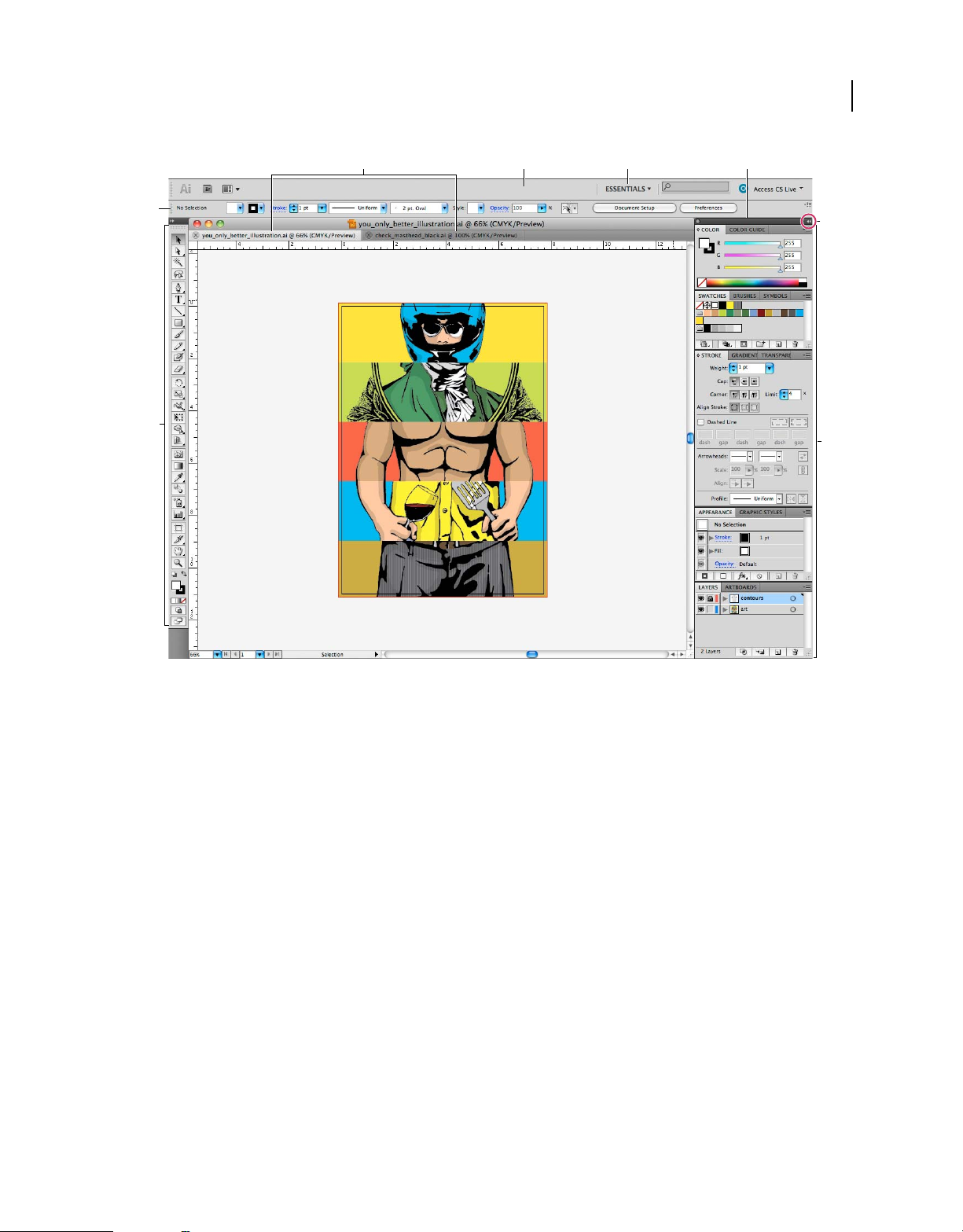
A
E
F
B DC
G
H
Default Illustrator workspace
A. Tabbed Document windows B. Application bar C. Workspace switcher D. Panel title bar E. Control panel F. Tools panel G. Collapse To
Icons button H. Four panel groups in vertical dock
• The Application bar across the top contains a workspace switcher, menus (Windows only), and other application
controls. On the Mac for certain products, you can show or hide it using the Window menu.
• The Tools panel contains tools for creating and editing images, artwork, page elements, and so on. Related tools are
grouped.
• The Control panel displays options for the currently selected tool. In Illustrator, the Control panel displays options
for the currently selected object. (In Adobe Photoshop® this is known as the Options bar. In Adobe Flash®, Adobe
Dreamweaver®, and Adobe Fireworks® this is known as the Property Inspector and includes properties of the
currently selected element.)
• The Document window displays the file you’re working on. Document windows can be tabbed and, in certain cases,
grouped and docked.
• Panels help you monitor and modify your work. Examples include the Timeline in Flash, the Brush panel in
Illustrator, the Layers panel in Adobe Photoshop®, and the CSS Styles panel in Dreamweaver. Panels can be
grouped, stacked, or docked.
• The Application frame groups all the workspace elements in a single, integrated window that lets you treat the
application as a single unit. When you move or resize the Application frame or any of its elements, all the elements
within it respond to each other so none overlap. Panels don’t disappear when you switch applications or when you
accidentally click out of the application. If you work with two or more applications, you can position each
application side by side on the screen or on multiple monitors.
Last updated 11/8/2011
Page 13

USING ILLUSTRATOR
Workspace
If you are using a Mac and prefer the traditional, free-form user interface, you can turn off the Application frame.
In Adobe Illustrator®, for example, select Window > Application Frame to toggle it on or off. (In Flash, the
Application frame is on permanently for Mac, and Dreamweaver for Mac does not use an Application frame.)
Hide or show all panels
• (Illustrator, Adobe InCopy®, Adobe InDesign®, Photoshop, Fireworks)To hide or show all panels, including the
Tools panel and Control panel, press
Tab.
• (Illustrator, InCopy, InDesign, Photoshop) To hide or show all panels except the Tools panel and Control panel,
press Shift+Tab.
You can temporarily display hidden panels if Auto-Show Hidden Panels is selected in Interface preferences. It’s
always on in Illustrator. Move the pointer to the edge of the application window (Windows®) or to the edge of the
monitor (Mac
OS®) and hover over the strip that appears.
• (Flash, Dreamweaver, Fireworks) To hide or show all panels, press F4.
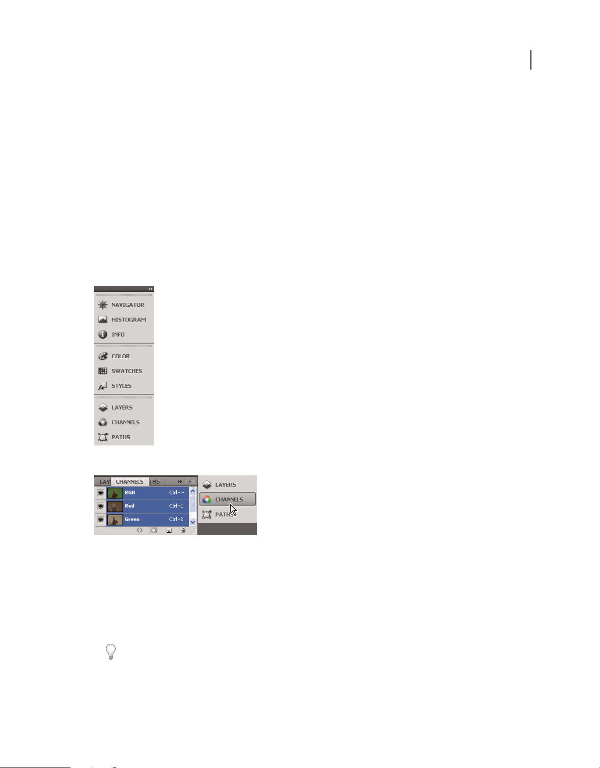
Display panel options
❖ Click the panel menu icon in the upper-right corner of the panel.
You can open a panel menu even when the panel is minimized.
7
In Photoshop, you can change the font size of the text in panels and tool tips. In the Interface preferences, choose a
size from the UI Font Size menu.
(Illustrator) Adjust panel brightness
❖ In User Interface preferences, move the Brightness slider. This control affects all panels, including the Control
panel.
Reconfigure the Tools panel
You can display the tools in the Tools panel in a single column, or side by side in two columns. (This feature is not
available in the Tools panel in Fireworks and Flash.)
In InDesign and InCopy, you also can switch from single-column to double-column (or single-row) display by setting
an option in Interface preferences.
❖ Click the double arrow at the top of the Tools panel.
Search For Help box
Use the Search For Help box on the right side of the Application bar to search for Help topics and online content. If
you have an active Internet connection, you can access all content on the Community Help website. If you search for
Help without an active Internet connection, search results are limited to Help content that is included with Illustrator.
1 In the search box, type the name of the item on which you want to search (such as a feature, application, or tool).
2 Press Enter.
All topics available from the Community Help center appear in a separate browser window.
Last updated 11/8/2011
Page 14

USING ILLUSTRATOR
Workspace
About screen modes
You can change the visibility of the illustration window and menu bar using the mode options at the bottom of the Tools
panel. To access panels when in Full Screen Mode, position the cursor at the left or right edge of the screen and the
panels will pop up. If you’ve moved them from their default locations, you can access them from the Window menu.
You can choose one of the following modes:
• Normal Screen Mode displays artwork in a standard window, with a menu bar at the top and scroll bars on the
sides.
• Full Screen Mode With Menu Bar displays artwork in a full-screen window, with a menu bar at the top and
scroll bars.
• Full Screen Mode displays artwork in a full-screen window, with no title bar or menu bar.
Using the status bar
The status bar appears at the lower-left edge of the illustration window. It displays any of the following:
• current zoom level
• current tool in use
• current artboard in use
• navigation controls for multiple artboards
• date and time
• number of undos and redos available
• document color profile
• status of a managed file
Click the status bar to do any of the following:
8
• Change the type of information displayed in the status bar by selecting an option from the Show submenu.
• Show the current file in Adobe Bridge by choosing Reveal In Bridge.
Enter values in panels and dialog boxes
You enter values using the same methods in all panels and dialog boxes. You can also perform simple math in any box
that accepts numeric values. For example, if you want to move a selected object 3 units to the right using the current
measurement units, you don’t have to work out the new horizontal position—simply type +3 after the current value
in the Transform panel.
Enter a value in a panel or dialog box
❖ Do any of the following:
• Type a value in the box, and press Enter or Return.
• Drag the slider.
• Drag the dial.
• Click the arrow buttons in the panel to increase or decrease the value.
• Click in the box and then use the Up Arrow key and Down Arrow key on the keyboard to increase or decrease the
value. Hold down Shift and click an arrow key to magnify the increase rate or decrease rate.
Last updated 11/8/2011
Page 15
USING ILLUSTRATOR
Workspace
• Select a value from the menu associated with the box.
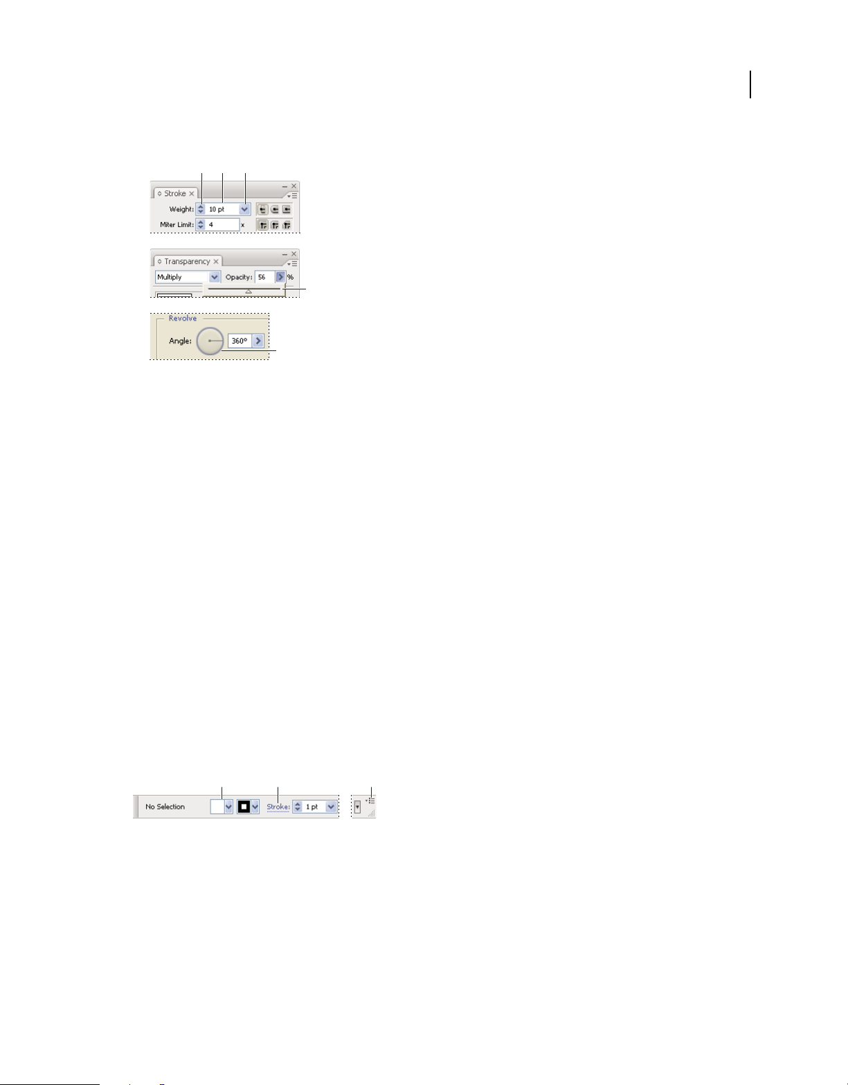
A B C
D
E
Ways to enter values
A. Arrow buttons B. Text box C. Menu arrow D. Slider E. Dial
Calculate values in a panel or dialog box
1 In a text box that accepts numerical values, do one of the following:
• To replace the entire current value with a mathematical expression, select the entire current value.
• To use the current value as part of a mathematical expression, click before or after the current value.
2 Type a simple mathematical expression using a single mathematical operator, such as + (plus), - (minus), x
(multiplication), / (division), or %
For example, 0p0 + 3 or 5mm + 4. Similarly, 3cm * 50% equals 3 centimeters multiplied by 50%, or 1.50 cm, and 50pt
+ 25% equals 50 points plus 25% of 50 points, or 62.5 points.
(percent).
9
3 Press Enter or Return to apply the calculation.
Control panel overview
The Control panel offers quick access to options related to the objects you select. By default, the Control panel is
docked at the top of the workspace.
Options displayed in the Control panel vary depending on the type of object or tool you select. For example, when you
select a text object, the Control panel displays text-formatting options in addition to options for changing the color,
placement, and dimensions of the object. When a selection tool is active, you can access Document Setup and
Preferences from the Control panel.
A B C
Control panel
A. Hidden options B. Link to another panel C. Panel menu
When text in the Control panel is blue and underlined, you can click the text to display a related panel or dialog box.
For example, click the word Stroke to display the Stroke panel.
Change the kinds of controls that appear in the Control panel
❖ Select or deselect options in the Control panel menu.
Last updated 11/8/2011
Page 16

USING ILLUSTRATOR
Workspace
Open and close a panel or dialog box from the Control panel
1 Click a blue underlined word to open its associated panel or dialog box.
2 Click anywhere outside of the panel or dialog box to close it.
Dock the Control panel at the bottom of the workspace
❖ Choose Dock To Bottom from the Control panel menu.
Convert the Control panel to a floating panel
❖ Drag the gripper bar (located on the left edge of the panel) away from its current position.
To redock the Control panel, drag the gripper bar to the top or bottom of the application window (Windows) or screen
OS).
(Mac
Customizing the workspace
Manage windows and panels
You can create a custom workspace by moving and manipulating Document windows and panels. You can also save
workspaces and switch among them. For Fireworks, renaming custom workspaces can lead to unexpected behavior.
10
Note: The following examples use Photoshop for demonstration purposes. The workspace behaves the same in all the
products.
Rearrange, dock, or float document windows
When you open more than one file, the Document windows are tabbed.
• To rearrange the order of tabbed Document windows, drag a window’s tab to a new location in the group.
• To undock (float or untab) a Document window from a group of windows, drag the window’s tab out of the group.
Note: In Photoshop you can also choose Window > Arrange > Float in Window to float a single Document window,
or Window > Arrange > Float All In Windows to float all of the Document windows at once. See tech note
for more information.
Note: Dreamweaver does not support docking and undocking Document windows. Use the Document window’s
Minimize button to create floating windows (Windows), or choose Window > Tile Vertically to create side-by-side
Document windows. Search “Tile Vertically” in Dreamweaver Help for more information on this topic. The workflow
is slightly different for Macintosh users.
• To dock a Document window to a separate group of Document windows, drag the window into the group.
• To create groups of stacked or tiled documents, drag the window to one of the drop zones along the top, bottom, or
sides of another window. You can also select a layout for the group by using the Layout button on the Application bar.
Note: Some products do not support this functionality. However, your product may have Cascade and Tile commands
in the Window menu to help you lay out your documents.
• To switch to another document in a tabbed group when dragging a selection, drag the selection over the document’s
tab for a moment.
Note: Some products do not support this functionality.
kb405298
Last updated 11/8/2011
Page 17
USING ILLUSTRATOR
Workspace
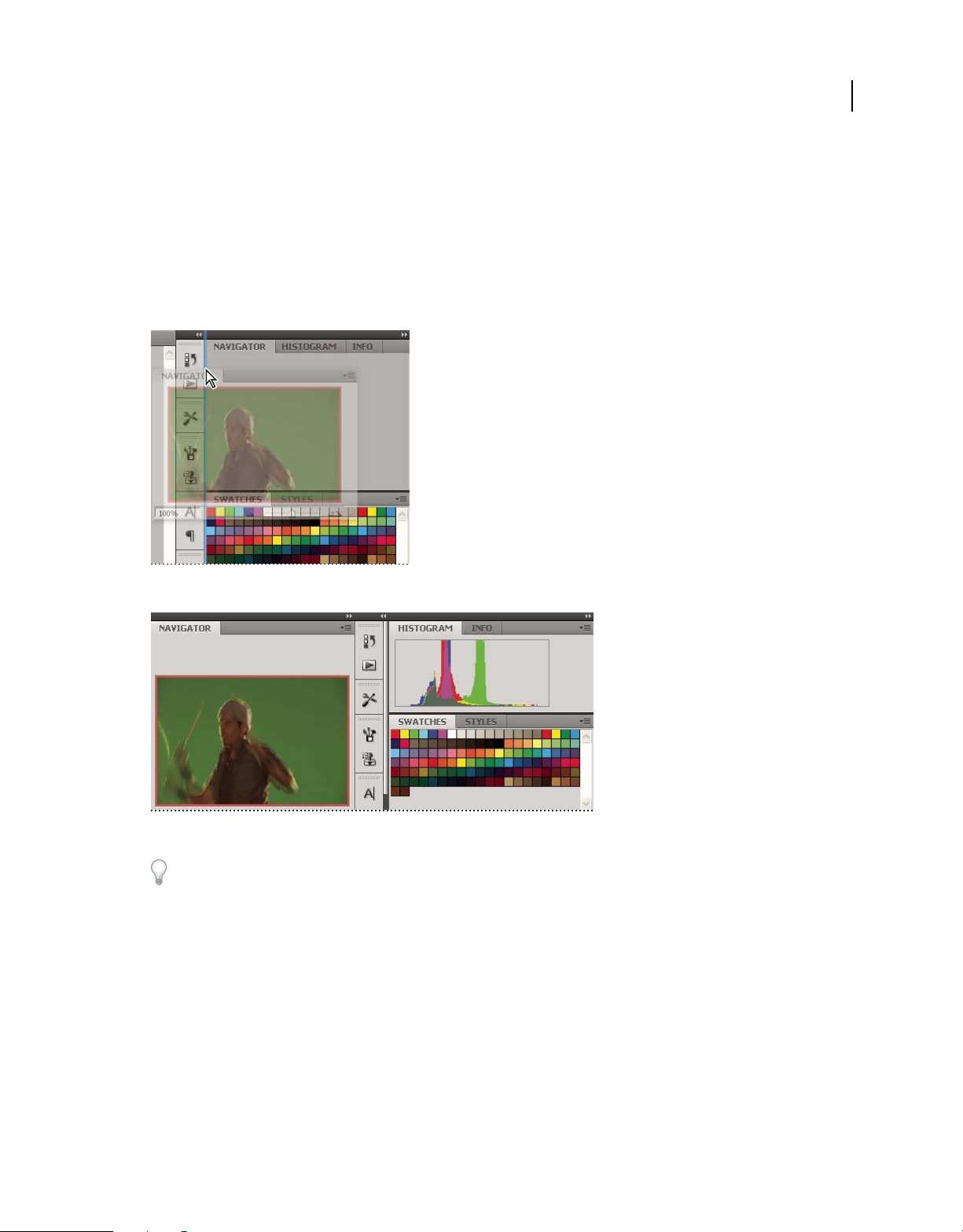
Dock and undock panels
A dock is a collection of panels or panel groups displayed together, generally in a vertical orientation. You dock and
undock panels by moving them into and out of a dock.
• To dock a panel, drag it by its tab into the dock, at the top, bottom, or in between other panels.
• To dock a panel group, drag it by its title bar (the solid empty bar above the tabs) into the dock.
• To remove a panel or panel group, drag it out of the dock by its tab or title bar. You can drag it into another dock
or make it free-floating.
11
Navigator panel being dragged out to new dock, indicated by blue vertical highlight
Navigator panel now in its own dock
You can prevent panels from filling all the space in a dock. Drag the bottom edge of the dock up so it no longer meets
the edge of the workspace.
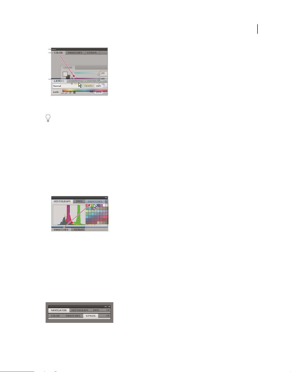
Move panels
As you move panels, you see blue highlighted drop zones, areas where you can move the panel. For example, you can
move a panel up or down in a dock by dragging it to the narrow blue drop zone above or below another panel. If you
drag to an area that is not a drop zone, the panel floats freely in the workspace.
Note: The position of the mouse (rather than the position of the panel), activates the drop zone, so if you can’t see the drop
zone, try dragging the mouse to the place where the drop zone should be.
• To move a panel, drag it by its tab.
• To move a panel group, drag the title bar.
Last updated 11/8/2011
Page 18
USING ILLUSTRATOR
Workspace
A
B
C
Narrow blue drop zone indicates Color panel will be docked on its own above the Layers panel group.
A. Title bar B. Tab C. Drop zone
Press Ctrl (Windows) or Command (Mac OS) while moving a panel to prevent it from docking. Press Esc while
moving the panel to cancel the operation.
Add and remove panels
If you remove all panels from a dock, the dock disappears. You can create a dock by moving panels to the right edge
of the workspace until a drop zone appears.
• To remove a panel, right-click (Windows) or Control-click (Mac) its tab and then select Close, or deselect it from
the Window menu.
• To add a panel, select it from the Window menu and dock it wherever you want.
12
Manipulate panel groups
• To move a panel into a group, drag the panel’s tab to the highlighted drop zone in the group.
Adding a panel to a panel group
• To rearrange panels in a group, drag a panel’s tab to a new location in the group.
• To remove a panel from a group so that it floats freely, drag the panel by its tab outside the group.
• To move a group, drag the title bar (the area above the tabs).
Stack floating panels
When you drag a panel out of its dock but not into a drop zone, the panel floats freely. The floating panel allows you
to position it anywhere in the workspace. You can stack floating panels or panel groups so that they move as a unit
when you drag the topmost title bar.
Free-floating stacked panels
• To stack floating panels, drag a panel by its tab to the drop zone at the bottom of another panel.
Last updated 11/8/2011
Page 19
USING ILLUSTRATOR
Workspace
• To change the stacking order, drag a panel up or down by its tab.
Note: Be sure to release the tab over the narrow drop zone between panels, rather than the broad drop zone in a title bar.
• To remove a panel or panel group from the stack, so that it floats by itself, drag it out by its tab or title bar.
Resize panels
• To minimize or maximize a panel, panel group, or stack of panels, double-click a tab. You can also double-click the
tab area (the empty space next to the tabs).
• To resize a panel, drag any side of the panel. Some panels, such as the Color panel in Photoshop, cannot be resized
by dragging.
Collapse and expand panel icons
You can collapse panels to icons to reduce clutter on the workspace. In some cases, panels are collapsed to icons in the
default workspace.
13
Panels collapsed to icons
Panels expanded from icons
• To collapse or expand all panel icons in a column, click the double arrow at the top of the dock.
• To expand a single panel icon, click it.
• To resize panel icons so that you see only the icons (and not the labels), adjust the width of the dock until the text
disappears. To display the icon text again, make the dock wider.
• To collapse an expanded panel back to its icon, click its tab, its icon, or the double arrow in the panel’s title bar.
In some products, if you select Auto-Collapse Icon Panels from the Interface or User Interface Options preferences,
an expanded panel icon collapses automatically when you click away from it.
• To add a floating panel or panel group to an icon dock, drag it in by its tab or title bar. (Panels are automatically
collapsed to icons when added to an icon dock.)
Last updated 11/8/2011
Page 20
USING ILLUSTRATOR
Workspace
• To move a panel icon (or panel icon group), drag the icon. You can drag panel icons up and down in the dock, into
other docks (where they appear in the panel style of that dock), or outside the dock (where they appear as floating
icons).
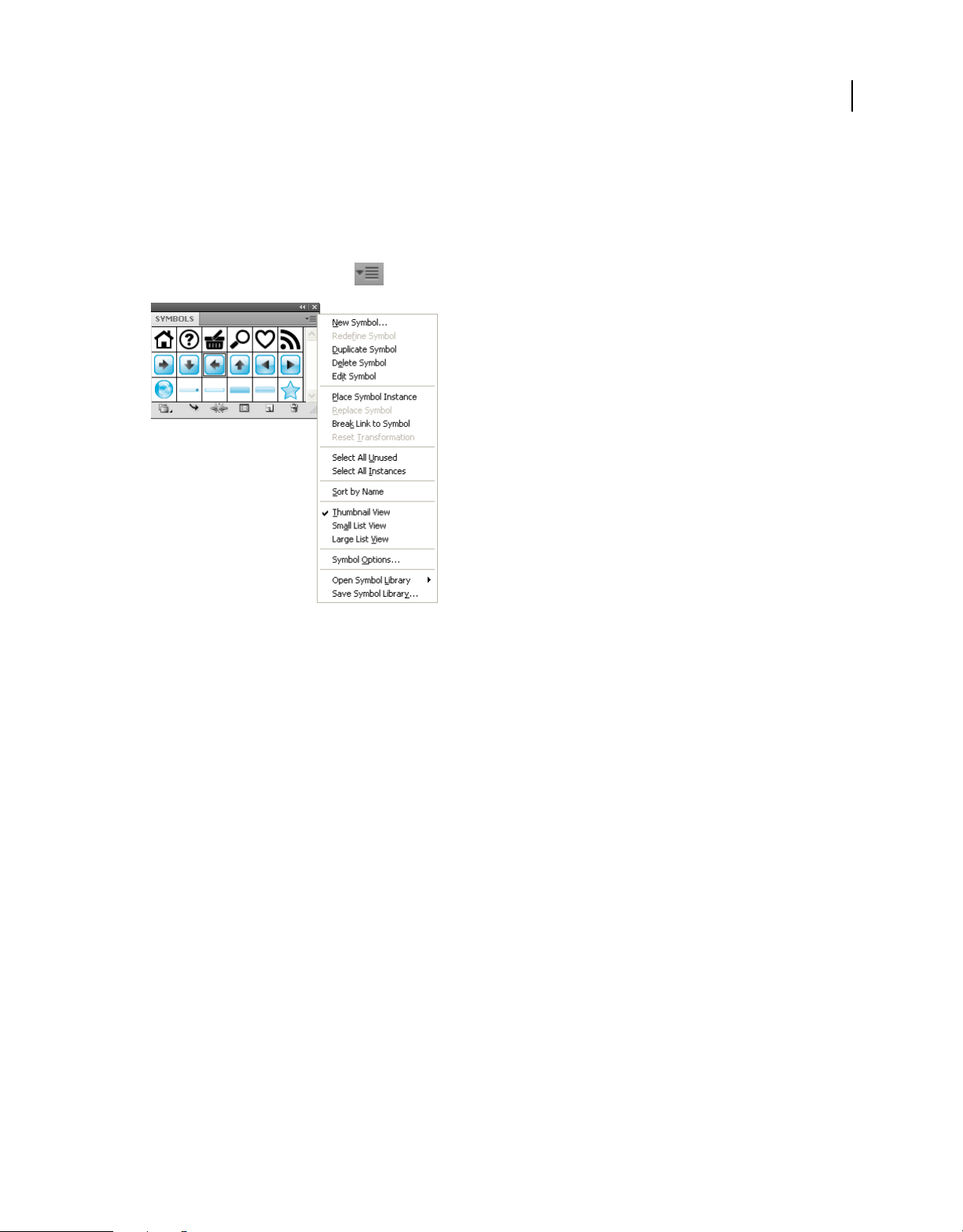
Use panel menus
Access the panel menus using the icon on the upper-right corner of the panel.
14
Panel menu (Symbols panel)
Rename or duplicate a workspace
1 Choose Window > Workspace > Manage Workspaces.
2 Do any of the following, and then click OK:
• To rename a workspace, select it, and edit the text.
• To duplicate a workspace, select it, and click the New button.
For a video on customizing the workspace based on different workflows, see www.adobe.com/go/vid0032_en.
Save and switch workspaces
By saving the current size and position of panels as a named workspace, you can restore that workspace even if you
move or close a panel. The names of saved workspaces appear in the workspace switcher in the Application bar.
Save a custom workspace
1 With the workspace in the configuration you want to save, do one of the following:
• (Illustrator) Choose Window > Workspace > Save Workspace.
• (Photoshop, InDesign, InCopy) Choose Window > Workspace > New Workspace.
• (Dreamweaver) Choose Window > Workspace Layout > New Workspace.
• (Flash) Choose New Workspace from the workspace switcher in the Application bar.
• (Fireworks) Choose Save Current from the workspace switcher in the Application bar.
2 Type a name for the workspace.
Last updated 11/8/2011
Page 21

USING ILLUSTRATOR
Workspace
3 (Photoshop, InDesign) Under Capture, select one or more options:
Panel Locations Saves the current panel locations (InDesign only).
Keyboard shortcuts Saves the current set of keyboard shortcuts (Photoshop only).
Menus or Menu Customization Saves the current set of menus.
Display or switch workspaces
❖ Select a workspace from the workspace switcher in the Application bar.
In Photoshop, you can assign keyboard shortcuts to each workspace to navigate among them quickly.
Delete a custom workspace
• Select Manage Workspaces from the workspace switcher in the Application bar, select the workspace, and then
click Delete. (The option is not available in Fireworks.)
• (Photoshop, InDesign, InCopy) Select Delete Workspace from the workspace switcher.
• (Illustrator) Choose Window > Workspace > Manage Workspaces, select the workspace, and then click the Delete icon.
• (Photoshop, InDesign) Choose Window > Workspace > Delete Workspace, select the workspace, and then click
Delete.
15
Restore the default workspace
1 Select the Default or Essentials workspace from the workspace switcher in the application bar. For Fireworks, see
the article
http://www.adobe.com/devnet/fireworks/articles/workspace_manager_panel.html.
Note: In Dreamweaver, Designer is the default workspace.
2 For Fireworks (Windows), delete these folders:
Windows Vista \\Users\<username>\AppData\Roaming\Adobe\Fireworks CS4\
Windows XP \\Documents and Settings\<username>\Application Data\Adobe\Fireworks CS4
3 (Photoshop, InDesign, InCopy) Select Window > Workspace > Reset [Workspace Name].
(Photoshop) Restore a saved workspace arrangement
In Photoshop, workspaces automatically appear as you last arranged them, but you can restore the original, saved
arrangement of panels.
• To restore an individual workspace, choose Window > Workspace > Reset Workspace Name.
• To restore all the workspaces installed with Photoshop, click Restore Default Workspaces in the Interface
preferences.
To rearrange the order of workspaces in the application bar, drag them.
Last updated 11/8/2011
Page 22

USING ILLUSTRATOR
Workspace
Tools
Tools panel overview
The first time you start the application, the Tools panel appears at the left side of the screen. You can move the Tools
panel by dragging its title bar. You can also show or hide the Tools panel by choosing Window
You use tools in the Tools panel to create, select, and manipulate objects in Illustrator. Some tools have options that
appear when you double-click a tool. These include tools that let you use type, and select, paint, draw, sample, edit,
and move images.
You can expand some tools to show hidden tools beneath them. A small triangle at the lower-right corner of the tool
icon signals the presence of hidden tools. To see the name of a tool, position the pointer over it.
You can also use the Tools panel to change the drawing mode from Draw Normal to Draw Behind or Draw Inside.
> Tools.
16
Last updated 11/8/2011
Page 23
USING ILLUSTRATOR
Workspace
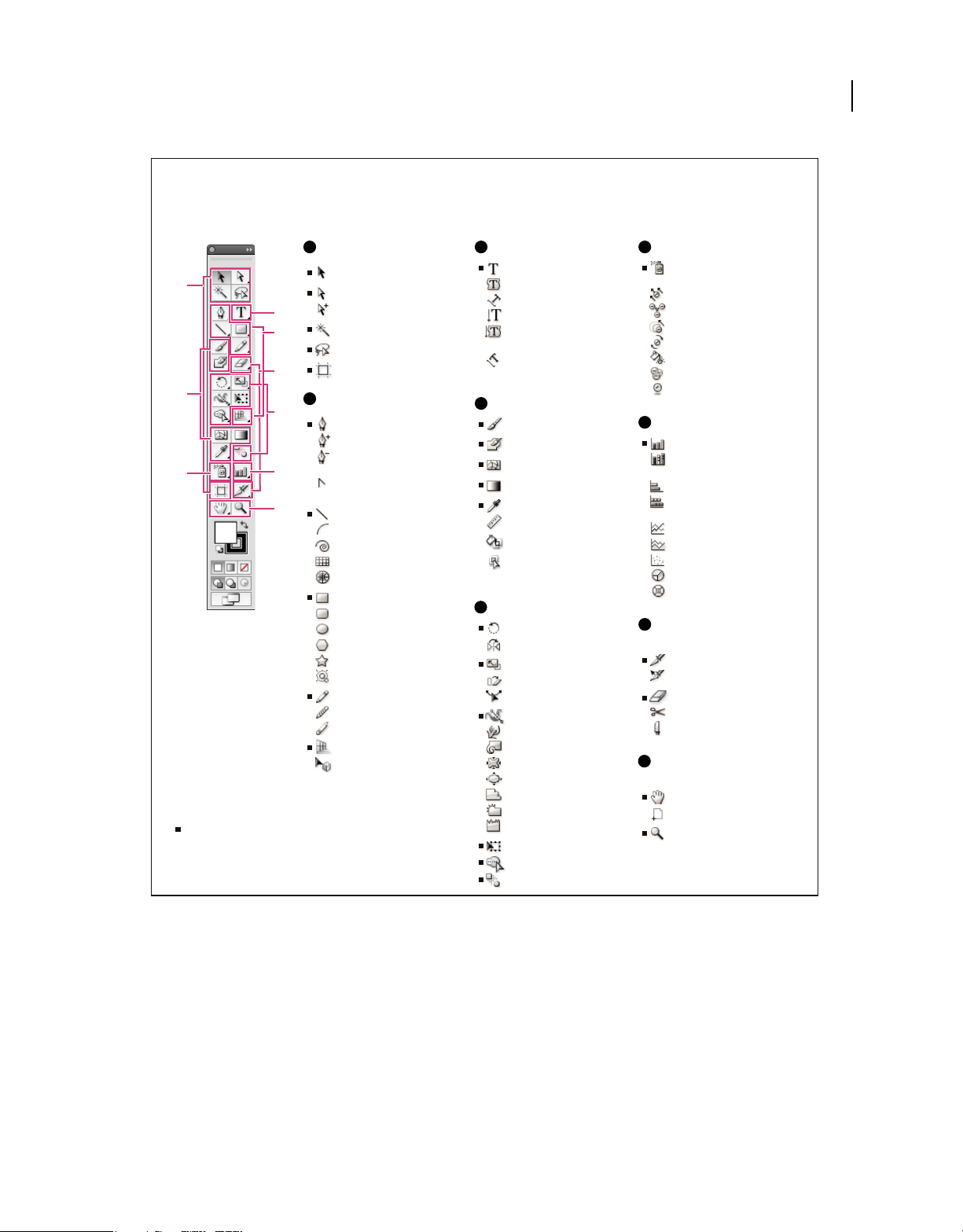
Tools panel overview
17
A
Selection tools
A
C
B
H
D
E
F
Indicates default tool
* Keyboard shortcuts appear in parenthesis
G
I
Selection (V)
Direct Selection (A)
Group Selection
Magic Wand (Y)
Lasso (Q)
Artboard (Shift +O)
B
Drawing tools
Pen (P)
Add Anchor Point (+)
Delete Anchor (-)
Point
Convert Anchor
Point (Shift+C)
Line Segment (\)
Arc
Spiral
Rectangular Grid
Polar Grid
Rectangle (M)
Rounded Rectangle
Ellipse (L)
Polygon
Star
Flare
Pencil (N)
Smooth
Path Eraser
Perspective Grid (Shift+P)
Perspective Selection
(Shift+V)
C
Type tools
Type (T)
Area Type
Type On a Path
Vertical Type
Vertical Area
Type
Vertical Type
On a Path
D
Painting tools
Paintbrush (B)
Blob Brush (Shift+B)
Mesh (U)
Gradient (G)
Eyedropper (I)
Measure
Live Paint Bucket (K)
Live Paint Selection
(Shift+L)
E
Reshaping tools
Rotate (R)
Reect (O)
Scale (S)
Shear
Reshape
Width (Shift+W)
Warp (Shift-R)
Twirl
Pucker
Bloat
Scallop
Crystallize
Wrinkle
Free Transform (E)
Shape Builder (Shift+M)
Blend (W)
F
Symbol tools
Symbol Sprayer
(Shift+S)
Symbol Shifter
Symbol Scruncher
Symbol Sizer
Symbol Spinner
Symbol Stainer
Symbol Screener
Symbol Styler
G
Graph tools
Column Graph (J)
Stacked Column
Graph
Bar Graph
Stacked Bar
Graph
Line Graph
Area Graph
Scatter Graph
Pie Graph
Radar Graph
H
Slicing and cutting
tools
Slice (Shift+K)
Slice Select
Eraser (Shift+E)
Scissors (C)
Knife
I
Moving and zooming
tools
Hand (H)
Print Tiling
Zoom (Z)
Tools panel overview
View hidden tools
❖ Hold down the mouse button on the visible tool.
View tool options
❖ Double-click a tool in the Tools panel.
Move the Tools panel
❖ Drag its title bar.
Last updated 11/8/2011
Page 24
USING ILLUSTRATOR
Workspace
View the Tools panel in double-stack or single-column
❖ Click the double-arrow on the title bar to toggle between double-stack and single-column view of the Tools panel.
Hide the Tools panel
❖ Choose Window > Tools.
Tear off hidden tools into a separate panel
❖ Drag the pointer over the arrow at the end of the hidden tools panel and release the mouse button.
Close a separate tool panel
❖ Click the close button on the panel’s title bar. The tools return to the Tools panel.
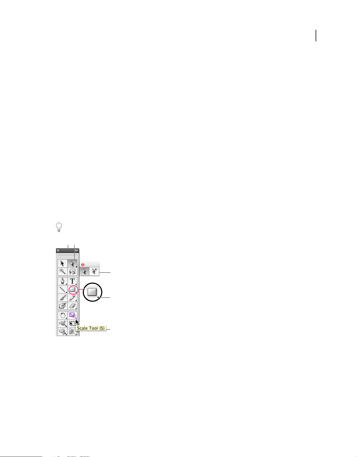
Select a tool
❖ Do one of the following:
• Click a tool in the Tools panel. If there is a small triangle at a tool’s lower-right corner, hold down the mouse button
to view the hidden tools, and then click the tool you want to select.
• Hold down Alt (Windows) or Option (Mac OS), and then click a tool to cycle through and select hidden tools.
• Press the tool’s keyboard shortcut. The keyboard shortcut is displayed in its tool tip. For example, you can select
the Move tool by pressing the V key.
To hide tool tips, choose Edit > Preferences > General (Windows) or Illustrator > Preferences > General (Mac OS),
and deselect Show Tool Tips.
18
A
B
C
D
E
Selecting a hidden tool
A. Tools panel B. Active tool C. Tear off panel with hidden tools D. Hidden tool triangle E. Tool name and shortcut
Change tool pointers
The mouse pointer for most tools matches the tool’s icon. Each pointer has a different hotspot, where an effect or
action begins. With most tools, you can switch to precise cursors, which appear as cross hairs centered around the
hotspot, and provide for greater accuracy when working with detailed artwork.
❖ Choose Edit > Preferences > General (Windows) or Illustrator > Preferences > General (Mac OS), and select Use
Precise Cursors. Alternatively, press Caps Lock on the keyboard.
Last updated 11/8/2011
Page 25
USING ILLUSTRATOR
Workspace
Tool galleries
Illustrator provides many tools for creating and manipulating your artwork. These galleries provide a quick visual
overview for each tool.
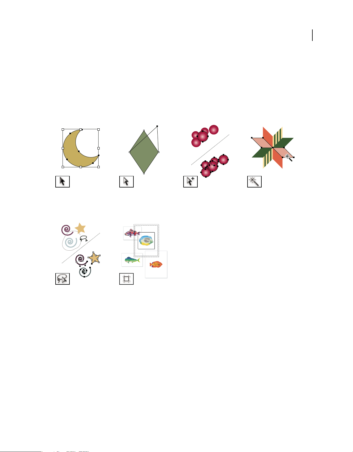
Selection tool gallery
Illustrator provides the following selection tools:
19
The Selection tool (V) selects
entire objects. See “Select objects
with the Selection tool” on
page 208.
The Lasso tool (Q) selects points
or path segments within objects.
See “Select objects with the Lasso
tool” on page 208.
The Direct Selection tool (A)
selects points or path segments
within objects. See “Select paths,
segments, and anchor points” on
page 71.
The Artboard tool creates
separate artboards for printing
or export. See “Create an
artboard” on page 36.
More Help topics
“Keys for selecting” on page 481
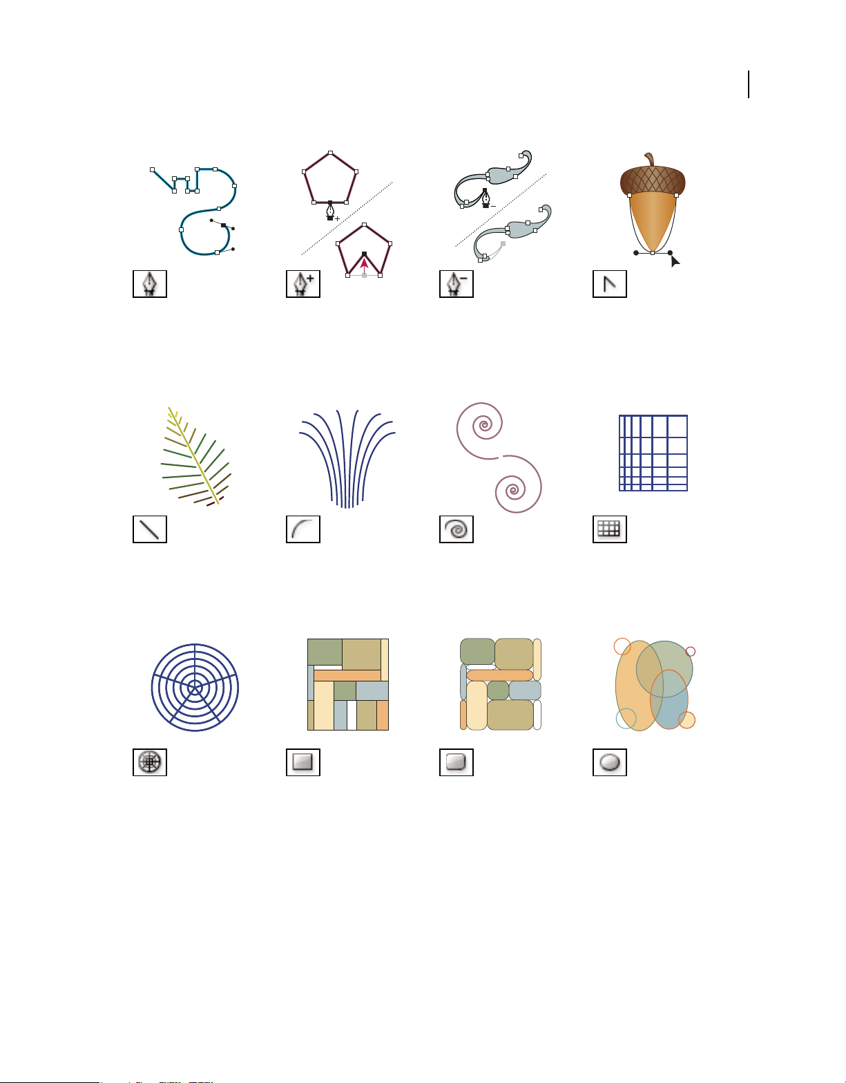
Drawing tool gallery
Illustrator provides the following drawing tools:
The Group Selection tool selects
objects and groups within
groups. See “Select objects and
groups with the Group Selection
tool” on page 211.
The Magic Wand tool (Y) selects
objects with similar attributes.
See “Select objects with the
Magic Wand tool” on page 208.
Last updated 11/8/2011
Page 26
USING ILLUSTRATOR
Workspace
20
The Pen tool (P) draws straight
and curved lines to create
objects. See “Drawing with the
Pen tool” on page 66.
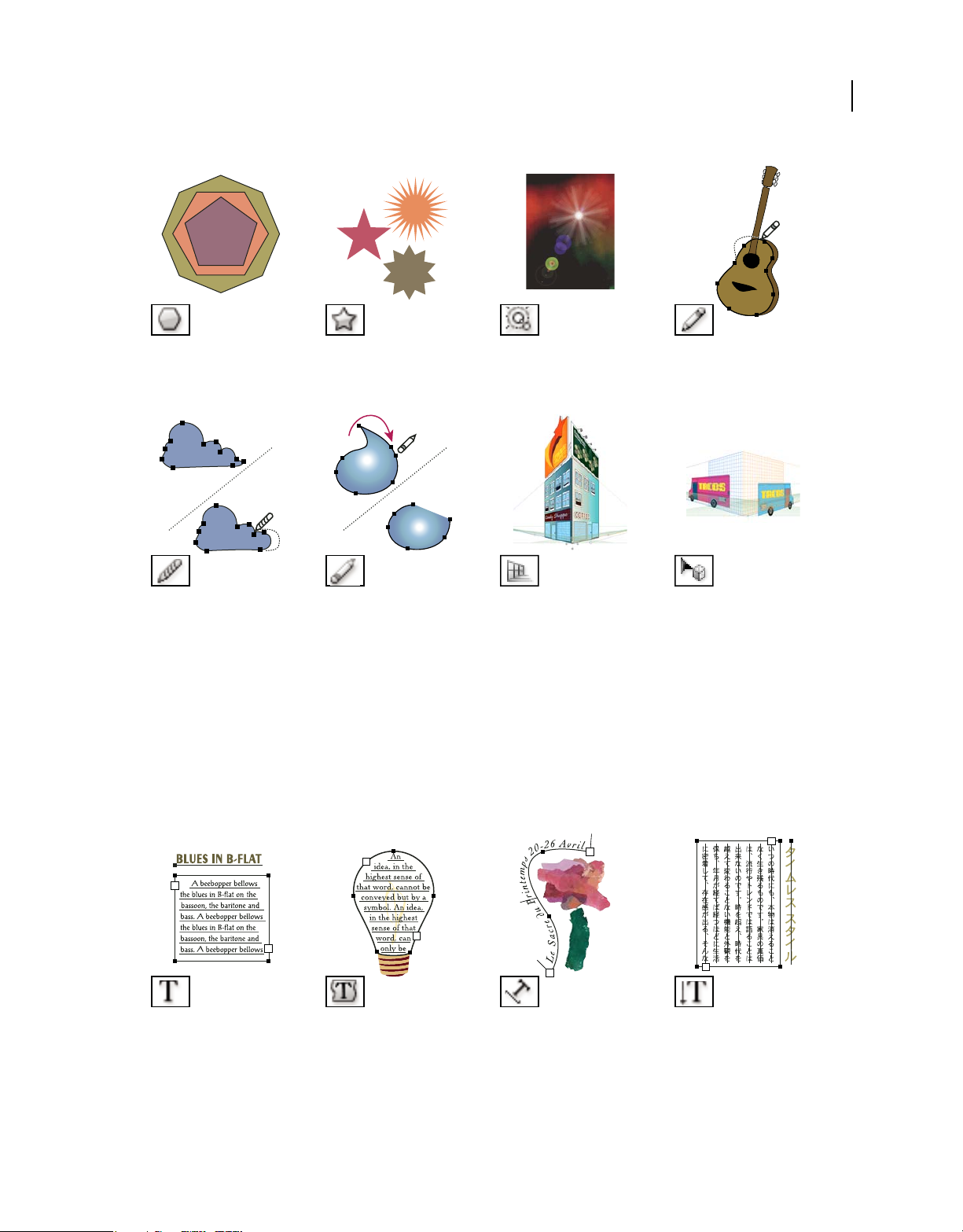
The Line Segment tool (\) draws
individual straight line
segments. See “Draw straight
lines with the Line Segment tool”
on page 56.
The Add Anchor Point tool (+)
adds anchor points to paths. See
“Adding and deleting anchor
points” on page 75.
The Arc tool draws individual
concave or convex curve
segments. See “Draw arcs” on
page 59.
The Delete Anchor Point tool (-)
deletes anchor points from
paths. See “Adding and deleting
anchor points” on page 75.
The Spiral tool draws clockwise
and counterclockwise spirals.
See “Draw spirals” on page 59.
The Convert Anchor Point tool
(Shift+C) changes smooth points
to corner points and vice versa.
See “Convert between smooth
points and corner points” on
page 77.
The Rectangular Grid tool
draws rectangular grids. See
“Draw rectangular grids” on
page 60.
The Polar Grid tool draws
circular chart grids. See “Draw
circular (polar) grids” on
page 60.
The Rectangle tool (M) draws
squares and rectangles. See
“Draw rectangles and squares”
on page 57.
Last updated 11/8/2011
The Rounded Rectangle tool
draws squares and rectangles
with rounded corners. See
“Draw rectangles and squares”
on page 57.
The Ellipse tool (L) draws circles
and ovals. See “Draw ellipses” on
page 57.
Page 27
USING ILLUSTRATOR
Workspace
21
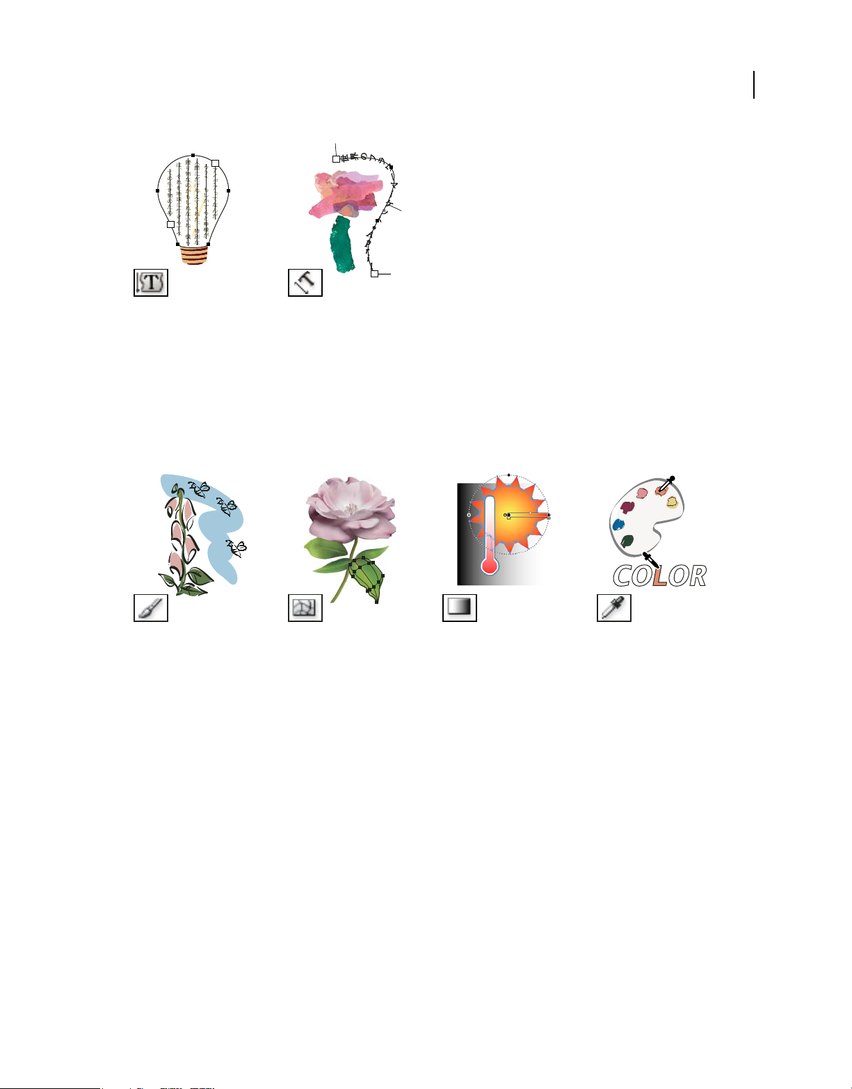
The Polygon tool draws regular,
multi-sided shapes. See “Draw
polygons” on page 58.
The Smooth tool smooths Bezier
paths. See “Smooth paths” on
page 76.
The Star tool draws stars. See
“Draw stars” on page 58.
The Path Eraser tool erases
paths and anchor points from
the object. See “Erase artwork”
on page 79.
Type tool gallery
Illustrator provides the following type tools:
The Flare tool creates lens-flare
or solar-flare-like effects. See
“Drawing flares” on page 112.
The Perspective Grid allows
creating and rendering artwork
in perspective. See “About
Perspective Grid” on page 81.
The Pencil tool (N) draws and
edits freehand lines. See
“Drawing with the Pencil tool”
on page 64.
The Perspective Selection tool
allows you to bring objects, text,
and symbols in perspective,
move objects in perspective,
move objects in perpendicular to
its current direction. See “About
Perspective Grid” on page 81.
.
The Type tool (T) creates
individual type and type
containers and lets you enter
and edit type. See “Enter text in
an area” on page 308.
The Area Type tool changes
closed paths to type containers
and lets you enter and edit type
within them. See “Enter text in
an area” on page 308.
Last updated 11/8/2011
The Type On A Path tool
changes paths to type paths, and
lets you enter and edit type on
them. See “Creating type on a
path” on page 315.
The Vertical Type tool creates
vertical type and vertical type
containers and lets you enter
and edit vertical type. See “Enter
text in an area” on page 308.
Page 28
USING ILLUSTRATOR
Workspace
22
The Vertical Area Type tool
changes closed paths to vertical
type containers and lets you
enter and edit type within them.
See “Enter text in an area” on
page 308.
The Vertical Type On A Path
tool changes paths to vertical
type paths and lets you enter and
edit type on them. See “Creating
type on a path” on page 315.
Painting tool gallery
Illustrator provides the following painting tools:
The Paintbrush tool (B) draws
freehand and calligraphic lines,
as well as art, patterns, and
bristle brush strokes on paths.
See “Draw paths and apply
brush strokes simultaneously”
on page 173.
The Mesh tool (U) creates and
edits meshes and mesh
envelopes. See “Create mesh
objects” on page 195.
The Gradient tool (G) adjusts
the beginning and ending points
and angle of gradients within
objects, or applies a gradient to
objects. See “Apply a gradient to
an object” on page 192.
The Eyedropper tool (I) samples
and applies color, type, and
appearance attributes, including
effects, from objects. See “Copy
appearance attributes using the
Eyedropper tool” on page 369.
Last updated 11/8/2011
Page 29
USING ILLUSTRATOR
Workspace
23
The Live Paint Bucket tool (K)
paints faces and edges of Live
Paint groups with the current
paint attributes. See “Paint with
the Live Paint Bucket tool” on
page 168.
The Live Paint Selection (ShiftL)tool selects faces and edges
within Live Paint groups. See
“Select items in Live Paint
groups” on page 166.
The Measure tool measures the
distance between two points. See
“Measure the distance between
objects” on page 48.
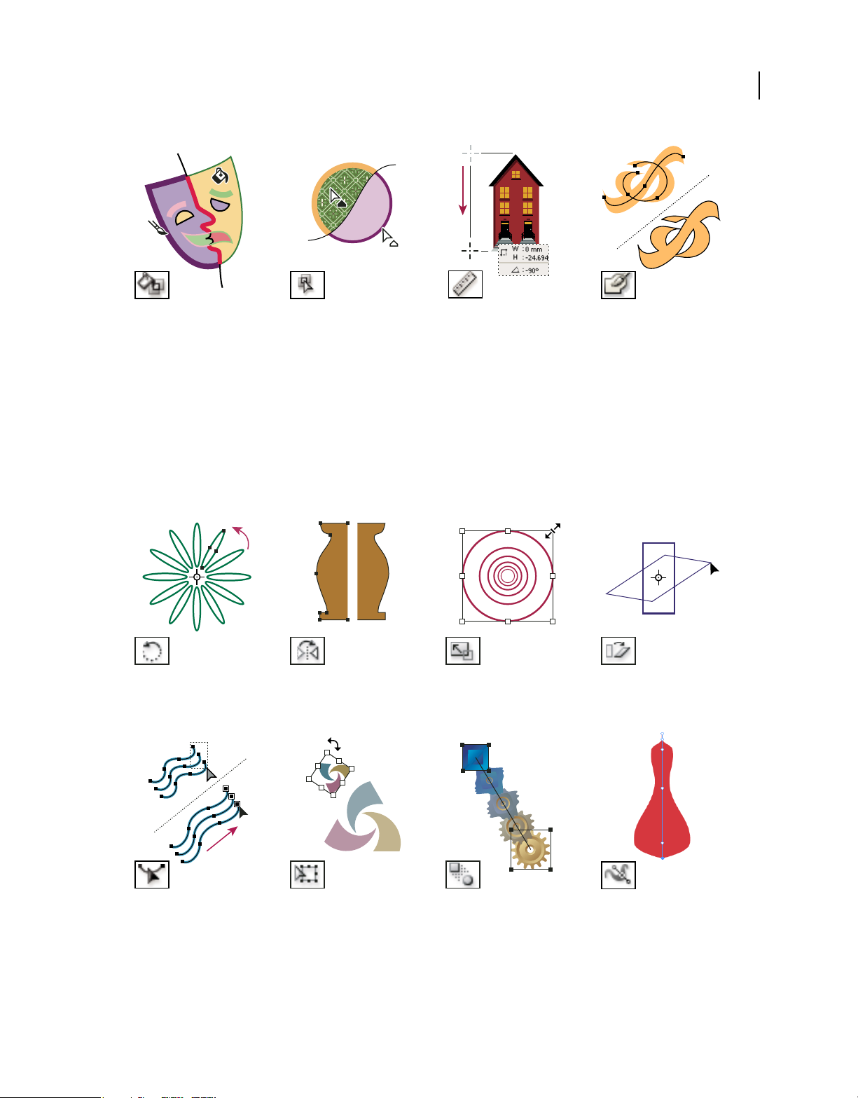
Reshaping tool gallery
Illustrator provides the following tools for reshaping objects:
The Rotate tool (R) rotates
objects around a fixed point. See
“Rotate objects” on page 219.
The Reflect tool (O) flips objects
over a fixed axis. See “Reflect or
flip objects” on page 221.
The Scale tool (S) resizes objects
around a fixed point. See “Scale
objects” on page 235.
The Blob Brush tool (ShiftB)draws paths that
automatically expand and
merge calligraphic brush paths
that share the same color and
are adjacent in stacking order.
See “Draw and merge paths with
the Blob Brush tool” on
page 157.
The Shear tool skews objects
around a fixed point. See “Shear
objects with the Shear tool” on
page 237.
The Reshape tool adjusts
selected anchor points while
keeping the overall detail of the
path intact. See
a path without distorting its
overall shape” on page 75.
“Stretch parts of
The Free Transform tool (E)
scales, rotates, or skews a
selection.
Last updated 11/8/2011
The Blend tool (W) creates a
series of objects blended between
the color and shape of multiple
objects. See
page 254.
“Create blends” on
The Width tool (Shift+W)
allows you to create a stroke
with variable width. See “Using
the Width tool” on page 160.
Page 30
USING ILLUSTRATOR
Workspace
24
The Warp tool (Shift+R) molds
objects with the movement of the
cursor (like molding clay, for
example). See “Distort objects
using a liquify tool” on page 239.
The Scallop tool adds random
curved details to the outline of
an object. See “Distort objects
using a liquify tool” on page 239.
The Twirl tool creates swirling
distortions within an object. See
“Distort objects using a liquify
tool” on page 239.
The Crystallize tool adds
random spiked details to the
outline of an object. See “Distort
objects using a liquify tool” on
page 239.
The Pucker tool deflates an
object by moving control points
towards the cursor. See “Distort
objects using a liquify tool” on
page 239.
The Wrinkle tool adds wrinklelike details to the outline of an
object. See “Distort objects using
a liquify tool” on page 239.
The Bloat tool inflates an object
by moving control points away
from the cursor. See “Distort
objects using a liquify tool” on
page 239.
The Shape Builder tool merges
simple shapes to create custom,
complex shapes. See “Building
new shapes using the Shape
Builder tool” on page 258.
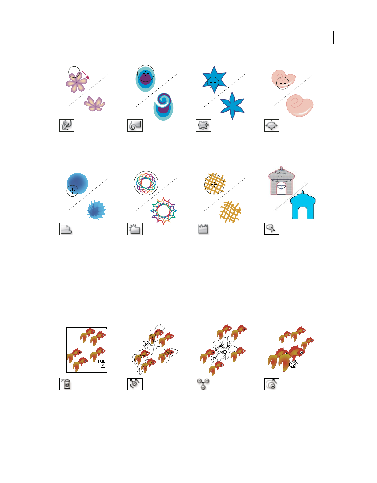
Symbolism tool gallery
The symbolism tools let you create and modify sets of symbol instances. You create a symbol set using the Symbol
Sprayer tool. You can then use the other symbolism tools to change the density, color, location, size, rotation,
transparency, and style of the instances in the set.
The Symbol Sprayer tool
(Shift+S) places multiple symbol
instances as a set on the
artboard. See
sets” on page 109.
“Create symbol
The Symbol Shifter tool moves
symbol instances and change
stacking order. See “Change
stacking order of symbol
instances in a set” on page 109.
Last updated 11/8/2011
The Symbol Scruncher tool
moves symbol instances closer
together or farther apart. See
“Gather or scatter symbol
instances” on page 110.
The Symbol Sizer tool resizes
symbol instances. See “Resize
symbol instances” on page 110.
Page 31

USING ILLUSTRATOR
Workspace
25
The Symbol Spinner tool rotates
symbol instances. See “Rotate
symbol instances” on page 110.
The Symbol Stainer tool
colorizes symbol instances. See
“Stain symbol instances” on
page 110.
The Symbol Screener tool
applies opacity to symbol
instances. See “Adjust
transparency of symbol
instances” on page 111.
The Symbol Styler tool applies
the selected style to symbol
instances. See “Apply a graphic
style to symbol instances” on
page 111.
Graph tool gallery
Illustrator provides nine graph tools, each one for creating a different type of graph. The type of graph you choose
depends on the information you want to communicate. See
80
70
60
50
40
30
20
10
0
B A
The Column Graph tool (J)
creates graphs that compare
values using vertical columns.
100
80
60
40
20
0
B A
The Stacked Column Graph tool
creates graphs that are similar to
column graphs, but stacks the
columns on top of one another,
instead of side by side. This
graph type is useful for showing
the relationship of parts to the
total.
“Create a graph” on page 463.
A
B
0 10 20 30 40 50 60 70 80
The Bar Graph tool creates
graphs that are similar to
column graphs, but positions the
bars horizontally instead of
vertically.
A
B
0 20 40 60 80 100
The Stacked Bar Graph tool
creates graphs that are similar to
stacked column graphs, but
stacks the bars horizontally
instead of vertically.
Last updated 11/8/2011
Page 32

USING ILLUSTRATOR
Workspace
26
80
70
60
50
40
30
20
50 40 30 20 10
The Line Graph tool creates
graphs that use points to
represent one or more sets of
values, with a different line
joining the points in each set.
This type of graph is often used
to show the trend of one or more
subjects over a period of time.
50
40
30
20
10
100
80
60
40
20
0
The Area Graph tool creates
graphs that are similar to line
graphs, but emphasizes totals as
well as changes in values.
50
40
30
20
10
0
10 20 30 40 50
The Scatter Graph tool creates
graphs that plot data points as
paired sets of coordinates along
the x and y axes. Scatter graphs
are useful for identifying
patterns or trends in data. They
also can indicate whether
variables affect one another.
D C B A
The Pie Graph tool creates
circular graphs whose wedges
represent the relative
percentages of the values
compared.
The Radar Graph tool creates
graphs that compare sets of
values at given points in time or
in particular categories, and is
displayed in a circular format.
This type of graph is also called a
web graph.
Slicing and cutting tool gallery
Illustrator provides the following tools for slicing and cutting objects:
The Slice tool divides artwork
into separate web
images.“Create slices” on
page 392
The Slice Selection tool (Shift-K)
selects web slices. See “Select
slices” on page 392
The Eraser tool (Shift-E) erases
any area of the object over which
you drag. See “Erase objects
using the Eraser tool” on page 79
The Scissors tool (C) cuts paths
at specified points. See “Split a
path” on page 80
Last updated 11/8/2011
Page 33

USING ILLUSTRATOR
Workspace
The Knife tool cuts objects and
paths. See “Cut objects with the
Knife tool” on page 250.
Moving and zooming tool gallery
Illustrator provides the following tools for moving around in and controlling the view of the artboard:
27
The Hand tool (H) moves the Illustrator
artboard within the illustration window.
The Print Tiling tool adjusts the page grid to
control where artwork appears on the
printed page.
The Zoom tool (Z) increases and decreases
the view magnification in the illustration
window.
Files and templates
About new document profiles
A document is the space in which you create artwork. In Illustrator, you can create documents destined for many
different types of output. (For information on creating Illustrator documents for video production, see the Enhancing
Video Production PDF at
You start a new document by choosing a new document profile based on your intended output. Each profile includes
preset values for size, color mode, units, orientation, transparency, and resolution. All use one artboard, by default. For
example, the Video And Film Document profile uses pixels instead of points, and you can choose a device-specific crop
area, such as NTSC DV Widescreen, to create a document in the exact dimensions required, with video-safe guides in
place to help you lay out your design for optimal viewing.
If you plan to output your file to a high-end printer, for example if you’re sending it to a service bureau, specify the
Print profile to ensure your artwork and any effects applied to the artwork are set to the proper resolution.
You can choose from the following profiles:
Print Document Uses a default letter size artboard, and provides a variety of other preset print sizes to choose from.
Use this profile if you plan to send this file to a service bureau for output to a high-end printer.
www.adobe.com/go/learn_ai_video.
Last updated 11/8/2011
Page 34

USING ILLUSTRATOR
Workspace
Web Document Provides preset options optimized for output to the web.
Flash Catalyst Creates an FXG document in RGB mode with 800px x 600px artboard as the default size. Align to Pixel
Grid is enabled for new art in the document and the Raster Effects Resolution is set to 72ppi. It also has Swatches,
Symbols, Graphic Styles and Brushes designed keeping Flash Catalyst and Flash Professional workflows in mind.
Mobile And Devices Document Creates a small file size that is preset for a specific mobile device. You can choose your
device from the Size menu. Click Device Central to open Adobe Device Central and view the document layout in a
specified device interface.
Video And Film Document Provides several preset video- and film-specific crop area sizes (note that the Artboard
option changes to Crop Size for this profile). Illustrator creates only square pixel files, so to ensure that the sizes are
interpreted correctly in video applications, Illustrator adjusts the Width and Height values. For example, if you choose
NTSC DV Standard, Illustrator uses a pixel size of 654 x 480, which translates to 740 x 480 pixels in video-based
applications.
Basic CMYK Document Uses a default letter size artboard, and provides a variety of other sizes to choose from. Use this
profile if you plan to send a document to multiple types of media. If one of the media types is a service bureau, you’ll
want to manually increase the Raster Effects setting to High.
Basic RGB Document Uses a default 800 x 600 size artboard, and provides a variety of other print-, video-, and web-
specific sizes to choose from. Do not use this option if you plan to send a document to a service bureau or output to a
high-end printer. Use this profile for documents that will be output to mid-level printers, to the web, or multiple types
of media.
28
For a video on setting up new documents, see www.adobe.com/go/vid0031.
For more information about creating custom new document profiles, see
www.adobe.com/go/learn_custom_document_profiles_en.
More Help topics
New document video
Video production
Create new documents
You can create new Illustrator documents from a new document profile or from a template. Creating a document from
a new document profile gives you a blank document with the selected profile’s default fill and stroke colors, graphic
styles, brushes, symbols, actions, viewing preferences, and other settings. Creating a document from a template gives
you a document with preset design elements and settings, as well as content, such as cropmarks and guides, for specific
document types, such as brochures or CD covers.
You create a new document from the Welcome screen, or by using File > New or File > Device Central (for mobile
device output). To view the Welcome screen, select Help > Welcome.
For a video on setting up new documents, see www.adobe.com/go/vid0031.
More Help topics
“About new document profiles” on page 27
“About templates” on page 30
“About transparency” on page 183
“Using Adobe Device Central with Illustrator” on page 389
Last updated 11/8/2011
Page 35

USING ILLUSTRATOR
Workspace
Create a new document
You can start a new document from the Welcome screen or from the File menu.
1 Do one of the following:
• If Illustrator is already open, choose File > New and from New Document Profile select the required document
profile.
• If the Welcome screen is open, click a document profile from the Create New list.
• If Illustrator is not open, open it and click a document profile from the Create New list in the Welcome screen.
Note: In the Welcome screen, you can Alt-click (Windows) or Option-click (Mac OS) to open the new document directly
and skip the New Document dialog box.
2 Type a name for your document.
3 Specify the number of artboards for your document, and the order you’d like them laid out on screen:
Grid By Row Arranges multiple artboards in the specified number of rows. Choose the number of rows from the Rows
menu. The default value creates the most square appearance possible with the specified number of artboards.
Grid By Column Arranges multiple artboards in the specified number of columns. Choose the number of columns
from the Columns menu. The default value creates the most square appearance possible with the specified number of
artboards.
29
Arrange By Row Arranges artboards in one straight row.
Arrange By Column Arranges artboards in one straight column.
Change To Right-To-Left Layout Arranges multiple artboards in the specified row or column format, but displays
them from right to left.
4 Specify the default spacing between artboards. This setting applies to both horizontal and vertical spacing.
5 Specify the default size, units of measure, and layout for all artboards.
Note: Once your document opens, you can customize your artboards by moving and resizing them as desired.
6 Specify the position of the bleed along each side of the artboard. To use different values for different sides, click the
Lock icon
7 Click Advanced to specify the following additional options:
.
Note: You can change these settings after you create the document by choosing File > Document Setup and specifying new
settings.
Color Mode Specifies the color mode for the new document. Changing the color mode converts the default contents
(swatches, brushes, symbols, graphic styles) of the selected new document profile to a new color mode, resulting in a
color change. Watch for a warning icon when making changes.
Raster Effects Specifies the resolution for raster effects in the document. It is especially important to set this at High
when you plan to output to a high-end printer at high resolution. The Print profile sets this at High by default.
Transparency Grid Specifies the options for the transparency grid for documents that use the Video And Film profile.
Preview Mode Sets the default preview mode for the document (you can change this at any time by using the View
menu):
• Default displays artwork created in the document in vector view with full color. Zoom in/out retains smoothness
in the curves.
• Pixel displays artwork with a rasterized (pixelated) appearance. It does not actually rasterize the content, but
displays a simulated preview, as if the contents were rasters.
Last updated 11/8/2011
Page 36

USING ILLUSTRATOR
Workspace
• Overprint provides an “ink preview” that approximates how blending, transparency, and overprinting will appear
in color-separated output. (See
Device Central If you’ve created a document using the Mobile and Devices profile, you can click Device Central to
preview your new document in the mobile device interface.
Align New Objects to Pixel Grid This option, if selected, aligns any new objects to the pixel grid. Because this option is
important for designs intended for display devices such as web, it is enabled by default for such documents. For more
information, see
“Drawing pixel-aligned paths for web workflows” on page 61.
“About overprinting” on page 441.)
Create a new document from a template
1 Do one of the following:
• Choose File > New From Template.
• Choose File > New. In the New Document dialog box, click Templates.
• In the Welcome screen, click From Template in the Create New list.
2 In the New From Template dialog box, locate and select a template, and click New.
About templates
Templates let you create new documents that share common settings and design elements. For example, if you need to
design a series of business cards with a similar look and feel, you can create a template with the desired artboard size,
view settings (such as guides), and print options. The template can also contain symbols for common design elements
(such as logos) and specific sets of color swatches, brushes, and graphic styles.
30
Illustrator comes with a variety of templates, including templates for letterhead, business cards, envelopes, brochures,
labels, certificates, postcards, greeting cards, and websites.
When a template is selected via the New From Template command, Illustrator creates a new document with identical
content and document settings as the template, but leaves the original template file untouched.
More Help topics
“Create new documents” on page 28
Create a new template
1 Open a new or existing document.
2 Customize the document in any of the following ways:
• Set up the document window as you want it to appear in new documents you create from the template. This
includes the magnification level, scroll position, ruler origin, guides, grids, crop areas, and options in the View
menu.
• Draw or import any artwork you want to appear in new documents you create from the template.
• Delete any existing swatches, styles, brushes, or symbols, you don’t want to retain.
• Create any new swatches, styles, brushes, and symbols, you want in the corresponding panels. You can also import
preset swatches, styles, brushes, symbols, and actions from a variety of libraries that come with Illustrator.
• Create any graph designs you want and add them to the Graph Design dialog box. You can also import preset graph
designs.
• Set the desired options in the Document Setup dialog box and Print Options dialog box.
Last updated 11/8/2011
Page 37

USING ILLUSTRATOR
Workspace
3 Choose File > Save As Template.
4 In the Save As dialog box, select a location for the file, enter a filename, and click Save.
Illustrator saves the file in AIT (Adobe Illustrator Template) format.
Specify document setup options
At any point you can change your document’s default setup options for units of measure, transparency grid display,
background color, and type settings such as language, quote style, superscript and subscript size, and exportability. The
Edit Artboards button closes this dialog box and activates the Artboard tool. Use this button if you want to modify
your artboards.
1 Choose File > Document Setup or click the Document Setup button in the Control panel (this button is visible when
nothing is selected).
2 Specify options as desired.
Note: The Simulate Colored Paper option is useful if you plan to print the document on colored paper. For example, if
you draw a blue object on a yellow background, the object appears green. The simulation is performed only when the
transparency grid is not shown.
For specific information on these options, see related topics.
31
More Help topics
“Change the unit of measurement” on page 44
“View transparency in artwork” on page 183
“Specify curly or straight quotes” on page 329
“Creating superscripts or subscripts” on page 329
Open a file
You can open files that were created in Illustrator as well as compatible files that were created in other applications.
• To open an existing file, choose File > Open. Locate the file, and click Open.
• To open a recently saved file, choose the file from the Open A Recent Item list in the Welcome screen, or choose
> Open Recent Files, and choose a file from the list.
File
• To open and preview a file using Adobe Bridge, choose File > Browse In Bridge to open Adobe Bridge. Locate the
file and choose File
More Help topics
“Importing Adobe PDF files” on page 276
“Importing EPS files” on page 277
“Importing artwork from Photoshop” on page 279
> Open With > Adobe Illustrator CS5.
Last updated 11/8/2011
Page 38

USING ILLUSTRATOR
Workspace
Browse for files using Adobe Bridge
Adobe® Bridge is a cross-platform application included with Adobe® Creative Suite® 5 components that helps you
locate, organize, and browse the assets you need to create print, web, video, and audio content. You can start Bridge
from any Creative Suite component, and use it to access both Adobe and non-Adobe asset types.
❖ To open Adobe Bridge, do one of the following from within Illustrator:
• Choose File > Browse In Bridge.
• Click the Adobe Bridge icon in the Control panel.
• Choose Reveal In Bridge from the status bar.
From Adobe Bridge, you can do any of the following:
• Manage image, footage, and audio files: Preview, search, sort, and process files in Bridge without opening individual
applications. You can also edit metadata for files, and use Bridge to place files into your documents, projects, or
compositions.
• Manage your photos: Import and edit photos from your digital camera card, group related photos in stacks, and
open or import Photoshop® Camera Raw files and edit their settings without starting Photoshop.
• Perform automated tasks, such as batch commands.
• Synchronize color settings across color-managed Creative Suite components.
• Start a real-time web conference to share your desktop and review documents.
32
Working with ConnectNow
Working with ConnectNow
Adobe® ConnectNow provides you with a secure, personal online meeting room where you can meet and collaborate
with others via the web in real time. With ConnectNow, you can share and annotate your computer screen, send chat
messages, and communicate using integrated audio. You can also broadcast live video, share files, capture meeting
notes, and control an attendee's computer.
You can access ConnectNow directly from the application interface.
1 Choose File > Share My Screen.
2 In the Sign In to Adobe CS Live dialog box, enter your email address and password, and click Sign In. If you don’t
have an Adobe ID, click the Create Adobe ID button.
3 To share your screen, click the Share My Computer Screen button at the center of the ConnectNow application
window.
For complete instructions on using ConnectNow, see Adobe ConnectNow Help.
For a video tutorial about using ConnectNow, see Using ConnectNow to share your screen (7:12). (This
demonstration is in Dreamweaver.)
Last updated 11/8/2011
Page 39

USING ILLUSTRATOR
Workspace
Using multiple artboards
Artboard overview
Artboards represent the regions that can contain printable artwork. You resize and set the orientation for your artwork
by choosing settings in the Artboard Options dialog box. (In Illustrator CS3 and earlier, you use the Document Setup
dialog box to change the document size and orientation.)
You can use artboards as crop areas for printing or placement purposes—they work the same way as crop areas work
in Illustrator CS3. Multiple artboards are useful for creating a variety of things such as multiple page PDFs, printed
pages with different sizes or different elements, independent elements for websites, video storyboards, or individual
items for animation in Adobe Flash or After Effects.
Note: If you created crop areas in an Illustrator CS3 document, the crop areas will be converted to artboards in CS5. You
may be prompted to specify how you want the crop areas to convert.
You can have 1 to 100 artboards per document depending on size. You can specify the number of artboards for a
document when you first create it, and you can add and remove artboards at any time while working in a document.
You can create artboards in different sizes, resize them by using the Artboard tool
on the screen—even overlapping one another. Illustrator CS5 also provides options to reorder and rearrange artboards
using the Artboards panel. You can also specify custom names for an artboard and set reference points for artboards.
, and position them anywhere
33
Viewing artboards and the canvas
You can view the page boundaries in relation to an artboard by showing print tiling (View > Show Print Tiling). When
print tiling is on, the printable and nonprintable areas are represented by a series of solid and dotted lines between the
outermost edge of the window and the printable area of the page.
Each artboard is bound by solid lines and represents the maximum printable area. To hide the artboard boundaries,
choose View
> Hide Artboards. The canvas is the area outside the artboard that extends to the edge of the 220 inch
square window. The canvas represents a space on which you can create, edit, and store elements of artwork before
moving them onto an artboard. Objects placed onto the canvas are visible on-screen, but they do not print.
To center an artboard and zoom it to fit the screen, click the artboard number in the status bar, located at the bottom
of the application window.
A
B
C
Illustration window
A. Printable area (determined by the specified printer) B. Canvas C. Artboard
Last updated 11/8/2011
Page 40

USING ILLUSTRATOR
Workspace
Printing and saving artboards
All artboards in a document share the same media type format, such as Print. You can print each artboard individually,
tiled, or combined into one page. If you save a multiple-artboard Illustrator document to a previous version of
Illustrator, such as CS3, you can choose to save each artboard as a separate file, along with a master file that includes
all artboards merged.
Illustrator CS4 allowed you to save artboards as separate files only when downsaved, but in Illustrator CS5, you can
save individual artboards for current versions as well. The options to save each artboard as a separate .ai file is available
in the Illustrator Options dialog box.
You can preview artboards from the print dialog box before printing them. The print settings you choose are applied
to all of the artboards you selected to print.
By default all artwork is cropped to an artboard and all artboards print as individual pages. Use the Range option in
the Print dialog box to print specific pages, select Ignore Artboards and specify placement options to combine all art
onto a single page or tile the artwork as desired.
In Illustrator CS5, artboards in a document can automatically rotate to print to the chosen media size. Select the AutoRotate check box in the Print dialog box to set auto rotation for Illustrator documents. For a document created in CS5,
Auto-Rotate is enabled by default.
For example, consider a document with both landscape (width is more than height) and portrait (height is more than
width) media size. If you select the paper size as portrait in the Size of the Print dialog box, then the landscape artboards
automatically rotate to portrait media when printing.
34
Note: If Auto-Rotate is selected, you cannot change the direction of the page.
More Help topics
“Change the page size and orientation” on page 420
“Reposition artwork on the page” on page 418
“Tile artwork on multiple pages” on page 419
Artboard options
You open the Artboard Options dialog box by double-clicking the Artboard tool , or clicking the Artboard tool and
then clicking Artboard Options button in the Control panel.
Preset Specifies artboard dimensions. These presets set the video ruler pixel aspect ratio appropriately for the specified
output.
Width and Height Specifies the size of the artboard.
Orientation Specifies portrait or landscape page orientation.
Constrain Proportions Keeps the aspect ratio of the artboard intact if you manually resize it.
X: and Y: Position Specifies the position of the artboard according to Illustrator’s workspace rulers. To view these
rulers, choose View
Show Center Mark Displays a point in the center of the artboard.
> Show Rulers.
Show Cross Hairs Displays cross lines through the center of each side of the artboard.
Show Video Safe Areas Displays guides that represent the areas that fall inside the viewable area of video. You want to
keep all text and art that must be viewable to users inside the video safe areas.
Last updated 11/8/2011
Page 41

USING ILLUSTRATOR
Workspace
Video Ruler Pixel Aspect Ratio Specifies the pixel aspect ratio used for the video rulers.
Fade Region Outside Artboard Displays the area outside of the artboard a darker shade than the area inside the
artboard when the Artboard tool is active.
Update While Dragging Keeps the area outside of the artboard darker as you drag to resize the artboard. If this is not
selected, the outside area displays in the same color as inside the artboard while resizing.
Artboards Indicates how many artboards exist.
Artboards panel
The Artboards panel allows you to perform various artboard operations such as:
• Add, reorder, rearrange, and delete artboards
• Reorder and renumber artboards
• Select and navigate through multiple artboards
• Specify artboard options such as presets, Artboard size, and relative artboard position
35
ABC
Artboards panel
A. Up and Down Arrows to reorder artboards in the Artboards panel B. Add new artboards C. Delete artboards
• To access the Artboards panel, click Window > Artboards.
• To add artboards, do any one of the following:
• Click the New Artboard icon at the bottom of the Artboards panel.
• Select the New Artboard option from the Artboards panel menu (flyout menu) of the Artboards panel.
• To delete a single artboard or multiple artboards, do the following:
• Select the artboard to delete. To delete multiple artboards, press Shift key, and click the artboards listed in the
Artboards panel.
• Click the Delete Artboard icon at the bottom of the Artboards panel or select the Delete option from the
Artboards panel menu (flyout menu). To delete multiple non-contiguous artboards, press Ctrl (Windows) or
Command (Mac OS) key and click the artboards from the Artboards panel.
• To rearrange artboards in the Artboards panel, select the Rearrange Artboards option from the Artboards panel
menu (flyout menu). Notice, however, that rearranging the artboards does not change the order the artboards.
• To duplicate artboards, do the following:
• Select the artboard that you want to duplicate. You can also duplicate artboards by dragging one or more
artboards on to the new artboard button in Artboards panel.
• From the Artboards panel menu, select Duplicate.
• To reset the artboard options, such as presets, artboard position, and display, select Artboards Options from the
Artboards panel menu (flyout menu).
Last updated 11/8/2011
Page 42

USING ILLUSTRATOR
Workspace
For a video on using the Artboards panel, see www.adobe.com/go/lrvid5202_ai_en.
Create an artboard
1 Do any of the following:
• To create a custom artboard, select the Artboard tool , and drag in the workspace to define the shape, size, and
location.
• To use a preset artboard, double-click the Artboard tool, select a preset in the Artboard Options dialog box, and
click OK. Drag the artboard to position it where you want.
• To create an artboard within an active artboard, hold down Shift and drag using the Artboard tool.
• To duplicate an existing artboard, select the Artboard tool, click to select the artboard you want to duplicate, and
click the New Artboard button in the Control panel
artboard. To create multiple duplicates, Alt-click as many times as you want. Or, using the Artboard tool, Alt-drag
(Windows) or Option-drag (Mac OS) the artboard you want to duplicate.
• To duplicate an artboard with the contents, select the Artboard tool, click to select the Move/Copy Artwork With
Artboard icon on the Control panel
If you want the artwork to contain a bleed, make sure that there’s enough artwork beyond the artboard rectangle to
accommodate the bleed.
, press Alt (Windows) or Option (Mac OS), and then drag.
; then click where you want to place the duplicated
36
2 To commit the artboard and exit the artboard-editing mode, click a different tool in the Tools panel or click Esc.
To see a video on using multiple artboards, see www.adobe.com/go/lrvid5202_ai_en.
Delete an artboard
❖ Click the artboard and press Delete, click Delete in the Control panel, or click the Delete icon in an
artboard’s upper-right corner. You can delete all but the last remaining artboard.
Select and view artboards
1 Select the Artboard tool .
2 Do any of the following:
• Click an artboard to make it active. (Clicking in or drawing over an artboard using a different tool will also make
the Artboard tool active.) If artboards overlap, the artboard with the left edge closest to the click location becomes
the active artboard.
• To navigate between artboards, press Alt (Windows) or Option (Mac OS) and click an arrow key.
• To view artboards and their contents as outlines, right-click and choose Outline. To see artwork again, right-click
and choose Preview.
Edit artboards
You can create multiple artboards for your document, but only one can be active at a time. When you have multiple
artboards defined, you can view them all by selecting the Artboard tool. Each artboard is numbered for easy reference.
You can edit or delete an artboard at any time, and you can specify different artboards each time you print or export.
1 Select the Artboard tool , click to select an artboard.
Last updated 11/8/2011
Page 43

USING ILLUSTRATOR
Workspace
2 Do any of the following:
• To resize the artboard, position the pointer on an edge or corner until the cursor changes to a double-sided arrow,
and then drag to adjust. Or, specify new Width and Height values in the Control panel.
• To change the orientation of the artboard, click the Portrait or Landscape button in the Control panel.
• To rotate between artboards, press Alt (Windows) or Option (Mac OS) and click an arrow key.
• To view artboards and their contents as outlines, right-click and choose Outline. To see artwork again, right-click
and choose Preview.
Move an artboard
1 Select the Artboard tool and click to select an artboard.
2 Do one of the following:
• To move the artboard and its contents, click to select the Move/Copy Artwork With Artboard icon on the Control
, and then position the pointer in the artboard and drag. Or, specify new X and Y values in the Control
panel
panel.
• To move the artboard without its contents, click to deselect the Move/Copy Artwork With Artboard icon on the
Control panel, and then position the pointer in the artboard and drag. Or, specify new X and Y values in the Control
panel.
37
Reorder artboards
In the Artboards panel, you can use the Up and Down Arrows at the bottom of the panel to reorder the artboards.
However, reordering artboards in the Artboards panel, does not reorder the artboards in the work area.
Rearrange artboards
To fit all artboards in view, you can rearrange artboards using the Grid by Row, Grid by Column, Arrange by Row, and
Arrange by Column options.
To rearrange artboards, do the following:
1 Click the Artboards panel menu (flyout menu) and select the Rearrange Artboards option.
2 In the Rearrange Artboards dialog box, select the layout. The options are:
Grid by Row Arranges multiple artboards in the specified number of rows. Specify the number of rows in the Rows
box. The default value creates the most square appearance possible with the specified number of artboards.
Grid by Column Arranges multiple artboards in the specified number of columns. Choose the number of columns
from the Columns menu. The default value creates the most square appearance possible with the specified number
of artboards.
Arrange by Row Arranges all the artboards in a single row.
Arrange by Column Arranges all the artboards in a single column.
Change to Right-to-Left Layout/Change to Left-to-Right Layout Arranges the artboards from left to right or right to
left. By default, artboards are arranged from left to right.
Note: If you select the Change to Right-to-Left Layout option, the Grid by Row and Grid Column options change to
Right-to-Left Grid by Row and Right-to-Left Grid by Column.
3 Specify the spacing between the artboards. This setting applies to both horizontal and vertical spacing.
Last updated 11/8/2011
Page 44

USING ILLUSTRATOR
Workspace
4 Select the Move Artwork with Artboard option to move the artwork whenever the artboards location changes.
Additionally, an artboard within an artboard is treated like a crop area and is moved along with the containing
artboard.
Customize artboard names
Each artboard can now be given a custom name, when in artboard edit mode.
To assign a custom name to an artboard, do the following:
1 Select the Artboard Tool to edit the artboard.
2 Select the artboard and specify the artboard name in the Name box of the Artboard Control Panel.
Alternatively, you can provide a custom name in the Name field of the Artboard Options dialog box. To open the
dialog box, click Artboard Options in the Artboards Panel menu (flyout menu). Click OK to commit the new name
for the chosen artboard.
The new artboard name appears on the upper-left side of the artboard. The custom name also shows up in the
Artboard Navigation field and drop-down next to document’s status area.
If you assign a custom name to artboards, these names are added as suffix to the filename while saving artboard specific
files to all formats.
38
Enter a custom name for an artboard in the Control panel.
Note: To return to the default name, clear the name of the artboard from the Name field in the Control panel.
9-point referencing
To set reference points for artboards, use the Artboard Options dialog box or the Artboard options in the Control
panel.
This option allows you to hinge a corner or center of an artboard while its size is being changed.
Display artboard rulers, center mark, crosshairs, or safe area
You can choose to display a center mark, cross hairs, video safe markers, and rulers around an artboard. Rulers are
useful when you’re working with art intended for export to video. The numbers on the rulers reflect device-specific
pixels, regardless of the measurement unit specified in preferences. The default Video Ruler Pixel Aspect Ratio
(VPAR) for Illustrator is 1.0 (for square pixels)—this value changes according to the preset you choose either in the
Artboard Options dialog box or the New Document dialog box.
If you’re using nonsquare pixels, the ruler provides for easier device-specific pixel calculations. For example, if you
specify an artboard of 100 x100 Illustrator points, and you want to know the exact size in device-dependent pixels
before exporting the file for use in a NTSC DV Widescreen, you can set the video ruler in Illustrator to use a video ruler
pixel aspect ratio of 1.2 (for wide pixels) and the ruler will reflect the change and display the artboard as 83 x100 device
pixels (100/1.2 = 83.333).
Last updated 11/8/2011
Page 45

USING ILLUSTRATOR
Workspace
Artboard with rulers
Display center mark, cross hairs, or video safe areas
The center mark, cross hairs, and video safe area are video properties that assist you in creating videos while using
Creative Suite products. To display these properties:
1 Double-click the Artboard tool in the Tools panel, or, with the Artboard tool active, click the Artboard Options
icon in the Control panel.
2 In the Display section, select the options you’d like displayed in your artboards.
Note: You can also set or remove the center point by clicking the Show Center Mark icon in the Control panel.
39
Viewing artwork
Specify Document Setup options
At any point you can change your document’s default setup options for units of measure, transparency grid display,
background color, and type settings such as language, quote style, superscript and subscript size, bleeds, and
exportability. The Edit Artboards button closes this dialog box and activates the Artboard tool.
1 Choose File > Document Setup, or click the Document Setup button in the Control panel. (This button is available
when nothing is selected.)
2 Specify options as desired.
3 If you want to edit artboards (for instance, to change from portrait to landscape orientation), click Edit Artboards
to enter artboard editing mode.
The Simulate Colored Paper option is useful if you plan to print the document on colored paper. For example, if you
draw a blue object on a yellow background, the object appears green. The simulation is only performed when the
transparency grid is not shown.
More Help topics
“Edit artboards” on page 36
“Change the unit of measurement” on page 44
“View transparency in artwork” on page 183
Last updated 11/8/2011
Page 46

USING ILLUSTRATOR
Workspace
“Specify curly or straight quotes” on page 329
“Creating superscripts or subscripts” on page 329
About print tiling
By default, Illustrator prints each artboard on a single sheet of paper. However, if the artwork is larger than the page
sizes available on your printer, you can print onto multiple sheets of paper.
Dividing an artboard to fit a printer’s available page sizes is called tiling. You can choose a tiling option in the General
section of the Print dialog box. To view the print tiling boundaries on the artboard, choose View
> Show Print Tiling.
40
Artboard divided into multiple page tiles
When you divide the artboard into multiple tiles, the pages are numbered from left to right and from top to bottom,
starting with page 1. These page numbers appear on-screen for your reference only; they do not print. The numbers
enable you to print all of the pages in the file or specify particular pages to print.
More Help topics
“Change the page size and orientation” on page 420
“Tile artwork on multiple pages” on page 419
Zoom in or out
There are several ways to zoom in or out of artwork.
• Select the Zoom tool . The pointer becomes a magnifying glass with a plus sign in its center. Click in the center
of the area that you want to magnify, or hold down Alt (Windows) or Option (Mac OS) and click in the center of
the area that you want to reduce. Each click magnifies or reduces the view to the previous preset percentage.
• Select the Zoom tool and drag a dotted rectangle, called a marquee, around the area you want to magnify. To move
the marquee around the artwork, hold down the spacebar, and continue dragging to move the marquee to a new
location.
• Choose View > Zoom In or View > Zoom Out. Each click magnifies or reduces the view to the next preset
percentage.
• Set the zoom level at the lower-left corner of the main window or in the Navigator panel.
• To display a file at 100%, choose View > Actual Size, or double-click the Zoom tool.
•
To fill the window with the selected artboard, choose View > Fit Artboard In Window, or double-click the Hand tool.
Last updated 11/8/2011
Page 47

USING ILLUSTRATOR
Workspace
• To view everything in the window, choose View > Fit All In Window.
More Help topics
“Moving and zooming tool gallery” on page 27
“Keys for viewing artwork” on page 478
Change the view area
You can bring a different area of the artboard into view by doing any of the following:
• Choose View > Actual Size to see all of your artboards in actual size.
• Choose View > Fit All In Window to zoom out so that all artboards are visible in on the screen.
• Choose View > Fit Artboard In Window to zoom in on the active artboard.
• In the Navigator panel, click the area of the thumbnail display that you want to view in the illustration window.
Alternatively, drag the proxy view area (the colored box) to a different area of the thumbnail display.
• Select the Hand tool , and drag in the direction you want the artwork to move.
More Help topics
“Moving and zooming tool gallery” on page 27
41
“Keys for viewing artwork” on page 478
Navigator panel overview
You use the Navigator panel (Window > Navigator) to quickly change the view of your artwork using a thumbnail
display. The colored box in the Navigator (called the proxy view area) corresponds to the currently viewable area in
the illustration window.
A
CDE FG
Navigator panel
A. Thumbnail display of artwork B. Panel menu button C. Zoom box D. Zoom Out button E. Proxy preview area F. Zoom slider G. Zoom
In button
You can customize the Navigator panel in the following ways:
• To display artwork outside the boundaries of the artboard in the Navigator panel, click View Artboard Contents
Only from the panel menu to deselect it.
• To change the color of the proxy view area, select panel Options from the panel menu. Select a preset color from
the Color menu, or double-click the color box to choose a custom color.
• To display dashed lines in the document as solid lines in the Navigator panel, select panel Options from the panel
menu and select Draw Dashed Lines As Solid Lines.
B
Last updated 11/8/2011
Page 48

USING ILLUSTRATOR
Workspace
More Help topics
“Manage windows and panels” on page 10
View artwork as outlines
By default, Adobe Illustrator sets the view so that all artwork is previewed in color. However, you can choose to display
artwork so that only its outlines (or paths) are visible. Viewing artwork without paint attributes speeds up the time it
takes to redraw the screen when working with complex artwork.
In Outline mode, linked files are displayed by default as outlined boxes with an X inside. To view the contents of linked
files, choose File
• To view all artwork as outlines, choose View > Outline. Choose View > Preview to return to previewing artwork in
color.
• To view all artwork in a layer as outlines, Ctrl-click (Windows) or Command-click (Mac OS) the eye icon for the
layer in the Layers panel. Ctrl-click (Windows) or Command-click (Mac
in color. The eye icon has a hollow center
view is enabled.
• To view all items in unselected layers as outlines, Alt+Ctrl-click (Windows) or Option+Command-click (Mac OS)
the eye icon for the selected layer. Alternatively, select Outline Others from the Layers panel menu.
You can return all items in the Layers panel to Preview mode by choosing Preview All Layers from the Layers panel
menu.
> Document Setup, and select Show Images In Outline Mode.
OS) again to return to previewing artwork
when Outline view is enabled and a filled center when Preview
42
More Help topics
“Layers panel overview” on page 223
Use multiple windows and views
You can open multiple windows of a single document at the same time. Each window can have different view settings.
example, you can set one window highly magnified for doing close-up work on some objects and create another
For
window less magnified for laying out those objects on the page.
(Windows) You can arrange multiple open windows to suit your needs, using options from the Window menu.
Cascade displays windows stacked and descending from the upper-left to the lower-right of the screen; Tile displays
windows edge to edge; Arrange Icons organizes minimized windows within the program window.
An alternative to creating multiple windows is creating multiple views. You can create and store up to 25 views for each
document.
Multiple windows and multiple views differ in the following ways:
• Multiple views are saved with the document, multiple windows are not.
• Multiple windows can be viewed at the same time.
• Multiple views can appear at the same time only if multiple windows are opened to display them in. Changing a
view alters the current windows, it does not open a new one.
Create a new window
❖ Choose Window > New Window.
Last updated 11/8/2011
Page 49

USING ILLUSTRATOR
Workspace
Create a new view
❖ Set up the view as you want, and then choose View > New View, enter a name for the new view, and click OK.
Rename or delete a view
❖ Choose View > Edit Views.
Switch between views
❖ Select a view name from the bottom of the View menu.
Previewing artwork in its final output medium
Illustrator provides the following ways to preview how aspects of artwork will look when printed or viewed on the web
or a mobile device:
Overprint Preview mode (View > Overprint Preview) Provides an “ink preview” that approximates how blending,
transparency, and overprinting will appear in color-separated output.
Separations Preview mode (Window > Separations Preview) Provides a preview of how the separations will look when
printed.
Pixel Preview mode (View > Pixel Preview) Approximates how your artwork will appear when it is rasterized and
viewed in a web browser.
43
Flattener Preview panel (Window > Flattener Preview) Highlights areas of the artwork that meet certain criteria for
flattening when saved or printed.
Soft-proofs Approximate how your document’s colors will appear on a particular type of monitor or output device.
Anti-aliasing Gives vector objects a smoother on-screen appearance and provides a better idea of how vector artwork
will look when printed on a PostScript® printer. Anti-aliasing is helpful because screen resolution is relatively limited,
but vector artwork is often printed at a high resolution. To
(Windows) or Illustrator
Device Central (File > Device Central) Lets you preview how your document will appear on a particular mobile phone
or device.
> Preferences > General (Mac OS), select Anti-aliased Artwork, and click OK.
turn on anti-aliasing, choose Edit > Preferences > General
More Help topics
“About overprinting” on page 441
“About pixel preview mode” on page 388
“Using Adobe Device Central with Illustrator” on page 389
“Preview which areas of artwork will be flattened” on page 438
Rulers, grids, guides, and crop marks
Use rulers
Rulers help you accurately place and measure objects in the illustration window or in an artboard. The point where 0
appears on each ruler is called the ruler origin.
Last updated 11/8/2011
Page 50

USING ILLUSTRATOR
Workspace
In Illustrator CS5, rulers are similar to other Creative Suite applications like InDesign and Photoshop. Illustrator
provides separate rulers for documents and artboards. You can select only one of these rulers at one point.
Note: Window rulers would be called Global rulers in this document.
Global rulers appear at the top and left sides of the illustration window. The default ruler origin is located at the top-
left corner of the illustration window.
Artboard rulers appear at the top and left sides of the active artboard. The default artboard ruler origin is located at the
top-left corner of the artboard.
The difference between artboard rulers and global rulers is that if you select artboard rulers, the origin point changes
based on the active artboard. In addition, you can have different origin points for artboard rulers. Now, if you change
the artboard ruler origin, the pattern fills in objects on the artboards are not affected.
The default origin point for the global ruler is at the upper-left corner of the first artboard and the default origin for
the artboard rulers is at the top left corner of the respective artboard.
• To show or hide rulers, choose View > Rulers > Show Rulers or View> Rulers > Hide Rulers.
• To toggle between artboard rulers and global rulers, click the View > Rulers > Change to Global Rulers or View >
Rulers > Change to Artboard Rulers. By default, artboard rulers are displayed, so Change to Global Rulers option
is displayed under Rulers sub-menu.
• To show or hide video rulers, choose View > Show Video Rulers or View > Hide Video Rulers.
• To change the ruler origin, move the pointer to the upper-left corner where the rulers intersect, and drag the pointer
to where you want the new ruler origin.
As you drag, a cross hair in the window and in the rulers indicates the changing Global ruler origin.
44
Note: Changing the Global ruler origin affects the tiling of patterns.
• To restore the default ruler origin, double-click the upper-left corner where the rulers intersect.
The coordinate system has now been switched to fourth quadrant, which was previously the first quadrant. In
Illustrator CS5, when you move downwards, the value of y-axis increases and if you move toward right, the value of xaxis increases.
For saving to legacy versions of Illustrator, the Global rulers remain at the position set in legacy document. Although,
the origin point does not move to upper left, the coordinate system changes to fourth quadrant.
The change in coordinate system and the ruler origin does not apply to scripting, which allows you to retain old scripts.
However, when you transform objects using scripting, the Y coordinate values differ from the values that you set in
the Illustrator user interface. For example, if you apply a move operation of say Y= +10 points, then to emulate the
same movement with scripting, apply a transformation of Y = -10pts.
Change the unit of measurement
The default unit of measurement in Illustrator is points (a point equals .3528 millimeter). You can change the unit that
Illustrator uses for general measurements, strokes, and type. You can override the default unit while entering values in
boxes.
• To change the default unit of measurement, choose Edit > Preferences > Units (Windows) or Illustrator >
Preferences
Options is selected in the Type preferences, you can also select a unit specifically for Asian type.
Note: The “General” measurement option affects rulers, measuring the distance between points, moving and
transforming objects, setting grid and guides spacing, and creating shapes.
> Units (Mac OS), and then select units for the General, Stroke, and Type options. If Show Asian
Last updated 11/8/2011
Page 51

USING ILLUSTRATOR
Workspace
• To set the general unit of measurement for the current document only, choose File > Document Setup, choose the
unit of measure you want to use from the Units menu, and click
OK.
• To change the unit of measurement when entering a value in a box, follow the value by any of the following
abbreviations: inch, inches, in, millimeters, millimetres, mm, Qs (one Q equals 0.25 millimeter), centimeters,
centimetres, cm, points, p, pt, picas, pc, pixel, pixels, and px.
When mixing picas and points, you can enter values as XpY, where X and Y are the number of picas and points (for
example, 12p6 for 12 picas, 6 points).
Use the grid
The grid appears behind your artwork in the illustration window, and it does not print.
• To use the grid, choose View > Show Grid.
• To hide the grid, choose View > Hide Grid.
• To snap objects to gridlines, choose View > Snap To Grid, select the object you want to move, and drag it to the
desired location.
When the object’s boundaries come within 2 pixels of a gridline, it snaps to the point.
Note: When the View > Pixel Preview option is selected, Snap To Grid changes to Snap To Pixel.
45
• To specify the spacing between gridlines, grid style (lines or dots), grid color, or whether grids appear in the front
or back of artwork, choose Edit
Grid (Mac
OS).
> Preferences > Guides & Grid (Windows) or Illustrator > Preferences > Guides &
Use guides
Guides help you align text and graphic objects. You can create ruler guides (straight vertical or horizontal lines) and
guide objects (vector objects that you convert to guides). Like the grid, guides do not print.
You can choose between two guide styles—dots and lines—and you can change the color of guides by using either
predefined guide colors or colors you select using a color picker. By default, guides are unlocked so that you can move,
modify, delete, or revert them, but you can choose to lock them into place.
• To show or hide guides, choose View > Guides > Show Guides or View > Guides > Hide Guides.
• To change guide settings, choose Edit > Preferences > Guides & Grid (Windows) or Illustrator > Preferences >
Guides & Grid (Mac
• To lock guides, select View > Guides > Lock Guides.
Create guides
1 If the rulers aren’t showing, choose View > Show Rulers.
2 Position the pointer on the left ruler for a vertical guide or on the top ruler for a horizontal guide.
3 Drag the guide into position.
You can also convert vector objects to guides by selecting them and choosing View > Guides > Make Guides.
OS).
To make working with multiple guides easier, move them into a separate layer.
4 If you want to restrict the guides to an artboard and not to the entire canvas, then select the Artboard tool and then
drag the guides on to the artboard.
Last updated 11/8/2011
Page 52

USING ILLUSTRATOR
Workspace
Move, delete, or release guides
1 If guides are locked, select View > Guides > Lock Guides.
2 Do any of the following:
• Move the guide by dragging or copying.
• Delete the guide by pressing Backspace (Windows) or Delete (Mac OS), or by choosing Edit > Cut or Edit > Clear.
• Delete all guides at once by choosing View > Guides > Clear Guides.
• Release the guide, turning it back into a regular graphic object, by selecting the guide and choosing View > Guides >
Release Guides.
Snap objects to anchor points and guides
1 Choose View > Snap To Point.
2 Select the object you want to move, and position the pointer on the exact point you want to align with anchor points
and guides.
Important: When snapping to a point, the snapping alignment depends on the position of the pointer, not the edges of
the dragged object.
3 Drag the object to the desired location.
When the pointer comes within 2 pixels of an anchor point or guide, it snaps to the point. The pointer changes from
a filled arrowhead to a hollow arrowhead when a snap occurs.
46
Smart Guides
Smart Guides are temporary snap-to guides that appear when you create or manipulate objects or artboards. They help
you align, edit, and transform objects or artboards relative to other objects, artboards, or both by snap-aligning and
displaying X, Y location and delta values. You can specify the type of smart guides and feedback that appear (such as
measurement labels, object highlighting, or labels) by setting the Smart Guides preferences.
To see a video on using smart guides, see www.adobe.com/go/lrvid4020_ai.
Use Smart Guides
Smart Guides are on by default.
1 Choose View > Smart Guides to turn guides on or off.
2 Use Smart Guides in the following ways:
• When you create an object with the pen or shape tools, use the Smart Guides to position a new object's anchor
points relative to an existing object. Or, when you create a new artboard, use Smart Guides to position it relative to
another artboard or an object.
• When you create an object with the pen or shape tools, or when you transform an object, use the smart guides’
construction guides to position anchor points to specific preset angles, such as 45 or 90 degrees. You set these angles
in the Smart Guides preferences.
• When you move an object or artboard, use the Smart Guides to align the selected object or artboard to other objects
or artboards. The alignment is based on the geometry of objects and artboards. Guides appear as the object
approaches the edge or center point of other objects.
Note: Press Ctrl (Windows) or Command (Mac OS) to use the alignment behavior from Illustrator CS3, which uses the
center point or edge of one object or artboard.
Last updated 11/8/2011
Page 53

USING ILLUSTRATOR
Workspace
• When you transform an object, Smart Guides automatically appear to assist the transformation.
You can change when and how Smart Guides appear by setting Smart Guide preferences.
Note: When Snap To Grid or Pixel Preview is turned on, you cannot use Smart Guides (even if the menu command is
selected).
Smart Guide preferences
Choose Edit > Preferences > Smart Guides (Windows) or Illustrator > Preferences > Smart Guides (Mac OS) to set the
following preferences:
Color Specifies the color of the guides.
Alignment Guides Displays guide lines that are generated along the center and edges of geometric objects, artboard,
and bleeds. They are generated when you move objects and when you perform operations such as drawing basic
shapes, using Pen tool, and transforming objects.
Anchor/Path Labels Displays information when paths intersect and when they are centered on an anchor point.
Measurement Labels Displays information for many tools (such as Drawing tools and Text tools) about the current
position the cursor as you position the cursor over an anchor point. While creating, selecting, moving, or transforming
objects it displays the x and y delta from the object’s original location. When you press Shift while using a drawing tool,
the starting location appears.
47
Object Highlighting Highlights the object below the pointer as you drag around it. The highlight color matches the
object’s layer color.
Transform Tools Displays information when you scale, rotate, and shear objects.
Construction Guides Displays guidelines as you draw new objects. You specify the angles at which you want guidelines
drawn from the anchor points of a nearby object. You can set up to six angles. Type an angle in the selected Angles
box, select a set of angles from the Angles pop-up menu, or select a set of angles from the pop-up menu and change
one of the values in the box to customize a set of angles. The preview reflects your settings.
Snapping Tolerance Specifies the number of points the pointer must be from another object for Smart Guides to take
effect.
Specify crop marks for trimming or aligning
In addition to specifying different artboards to crop artwork for output, you can also create and use multiple sets of
crop marks within your artwork. Crop marks indicate where you want the printed paper to be cut. Crop marks are
useful when you want to create marks around several objects on a page—for example, when printing a sheet of business
cards. They are also helpful for aligning Illustrator artwork that you’ve exported to another application.
Crop marks differ from the artboard in the following ways:
• Artboards specify the printable boundaries of artwork, whereas crop marks don’t affect the printed area at all.
• You can activate only one artboard at a time, whereas you can create and display multiple crop marks.
• The artboard is indicated by visible but non-printing marks, whereas crop marks are printed with registration black
(so that they print to every separation plate, similar to printer’s marks).
Note: Crop marks do not replace trim marks created with the Marks & Bleed options in the Print dialog box.
Create crop marks around an object
In Illustrator CS5, you can create editable trim/crop marks or create crop marks as live effects.
Last updated 11/8/2011
Page 54

USING ILLUSTRATOR
Workspace
To use crop marks, do the following:
1 Select the object.
2 To create editable trim marks or crop marks, select Object > Create Trim Marks.
3 To create crop marks as live effect, select Effect > Crop Marks.
Delete crop marks
To delete an editable crop or trim marks, select the trim marks and press the Delete key.
To delete a crop marks effect, select Crop Marks in the Appearance panel, and click the Delete Selected Item icon .
Use Japanese-style crop marks
Japanese-style crop marks have double lines, which visually define a default bleed value of 8.5 points (3 millimeters).
1 Choose Edit > Preferences > General (Windows) or Illustrator > Preferences > General (Mac OS).
2 Select Use Japanese Crop Marks, and then click OK.
Measure the distance between objects
The Measure tool calculates the distance between any two points and displays the results in the Info panel.
48
1 Select the Measure tool . (Press and hold the Eyedropper tool to see it in the Tools panel.)
2 Do one of the following:
• Click the two points to measure the distance between them.
• Click the first point and drag to the second point. Shift-drag to constrain the tool to multiples of 45°.
The Info panel shows the horizontal and vertical distances from the x and y axes, the absolute horizontal and vertical
distances, the total distances, and the angle measured.
Info panel overview
You use the Info panel (Window > Info) to get information on the area beneath the pointer and on selected objects.
• When an object is selected and a selection tool is active, the Info panel displays the object’s x and y coordinates,
width (W), and height (H). The values for width and height are affected by the Use Preview Bounds option in the
General preferences. When Use Preview Bounds is selected, Illustrator includes the stroke width (and other
attributes such as drop shadows) in the object’s dimensions. When Use Preview Bounds is deselected, Illustrator
measures only the dimensions defined by the object’s vector path.
• When you use the Pen tool or Gradient tool, or when you move a selection, the Info panel displays the change in x
(W), the change in y (H), the distance (D), and the angle
• When you use the Zoom tool, the Info panel displays the magnification factor and the x and y coordinates after you
release the mouse button.
• When you use the Scale tool, the Info panel displays the percentage change in width (W) and height (H) and the
new width (W) and height (H) after the scaling is complete. When you use the rotate or reflect tools, the Info panel
displays the coordinates of the object’s center and the angle of rotation
• When you use the Shear tool, the Info panel displays the coordinates of the object’s center, the angle of shear
, and the amount of shear .
axis
• When you use the Paintbrush tool, the Info panel displays the x and y coordinates and the name of the current
brush.
as you drag.
or reflection .
Last updated 11/8/2011
Page 55

USING ILLUSTRATOR
Workspace
• Select Show Options from the panel menu or click the double arrow on the panel tab to show values for the fill and
stroke colors of the selected object and the name of any pattern, gradient, or tint applied to the selected object.
Note: If you select multiple objects, the Info panel displays only the information that is the same for all selected objects.
Setting preferences
About preferences
Preferences are options regarding how you want Illustrator to work, including those for display, tools, ruler units, and
exporting information. Your preferences are saved in a file called AIPrefs (Windows) or Adobe Illustrator Prefs
OS), which is launched each time you start Illustrator.
(Mac
Open a preferences dialog box
1 Do one of the following:
• (Windows) Choose Edit > Preferences > [preference set name].
• (Mac OS) Choose Illustrator > Preferences > [preference set name].
• With nothing selected, click the Preferences button on the Control panel.
2 To switch to a different preference set, do one of the following:
• Select an option from the menu at the upper-left of the Preferences dialog box.
• Click Next to display the next options, or click Prev to display the previous options.
49
Reset all preferences to default settings
Resetting preferences can be helpful if you are having problems with the application.
❖ Do one of the following:
• Press and hold Alt+Control+Shift (Windows) or Option+Command+Shift (Mac OS) as you start Illustrator.
Your current settings are deleted.
• Remove or rename the AIPrefs file (Windows) or Adobe Illustrator Prefs file (Mac OS). New preferences files
are created the next time you start Illustrator.
Note: It is safe to remove the entire Adobe Illustrator CS5 Settings folder. This folder contains various preferences
that can be regenerated.
Setting Illustrator preferences
The Illustrator preferences file manages the commands and panel settings in Illustrator. When you open Illustrator,
the positioning of panels and commands are stored in the Illustrator preferences file. If you want to restore the default
settings for Illustrator or change the current settings, delete the Illustrator preferences. Illustrator automatically creates
a preference file, when you restart Illustrator and save a file.
Depending on the operating system that you are using, the Illustrator preferences file is available at the following
location:
Note: The folder name may vary depending on the language version you have installed.
Mac OS X
Last updated 11/8/2011
Page 56

USING ILLUSTRATOR
Workspace
<startup drive>/Users/<username>/Library/Preferences/Adobe Illustrator CS5
Settings/en_US*/Adobe Illustrator Prefs
Windows XP
<startup drive>\ Documents and Settings\<username>\Application Data\Adobe\Adobe Illustrator
CS5 Settings\en_US*\AIPrefs
Windows Vista or Windows 7
<startup drive>\Users\<username>\AppData\Roaming\Adobe\Adobe Illustrator CS5
Settings\en_US*\AIPrefs.
Note: In Windows XP, the Application Data folder is hidden by default. The same is true for the AppData folder in
Windows Vista and Windows 7. To make this folder visible, open Folder Options in Control Panel and click the View tab.
In the Advanced Settings pane, select the Show Hidden Files and Folders or Show hidden files, folders, or drives option.
If you cannot locate the preferences file, use your operating system’s Find command, and search for AIPrefs
(Windows) or Adobe Illustrator Prefs (Mac OS).
About plug-in modules
Plug-in modules are software programs that add features to Adobe Illustrator. A number of special effects plug-ins
come with your program and are automatically installed in the Plug-ins folder inside the Illustrator folder.
50
You can install any commercial plug-in designed for use with Photoshop or Illustrator. To install an Adobe Systems
plug-in module, use the installer if one is provided. Otherwise, drag a copy of the module to the Plug-ins folder inside
the Illustrator folder. Then restart Illustrator for the plug-in to take effect. To install a third-party plug-in module,
follow the installation instructions that came with the plug-in module.
Note: The open architecture of the Adobe Illustrator program allows developers outside of Adobe to create features that
are accessible from within Adobe Illustrator. If you are interested in creating plug-in modules compatible with Adobe
Illustrator, see the Adobe Systems U.S. website at www.adobe.com.
Recovery, undo, and automation
Undo and redo changes
The Undo and Redo commands let you undo or redo operations, allowing you to correct mistakes as you work. You
can undo or redo an operation after you select the Save command (but not if you have closed and then reopened the
file).
❖ Choose Edit > Undo or Edit > Redo.
You can undo an unlimited number of operations (depending on memory) by repeatedly choosing the Undo
command. If an operation cannot be undone, the Undo command is dimmed.
Revert to the last saved version
You can revert a file to the last saved version (but not if you have closed and then reopened the file). You cannot undo
this action.
❖ Choose File > Revert.
Last updated 11/8/2011
Page 57

USING ILLUSTRATOR
Workspace
Automating tasks
Graphic design is a field characterized by creativity, but there are some aspects of the actual work of illustration that can
be repetitious. In fact, you’ll probably notice that the time you spend placing and replacing images, correcting errors,
and preparing files for printing and web display often reduces the time you have available for doing creative work.
Illustrator provides a variety of ways to automate many of the repetitive tasks you have to do, leaving more time to
concentrate on the creative aspects of your work.
An action is a series of tasks that are recorded while using the Illustrator application—menu commands, tool options,
object selection, and so on. When you play an action, Illustrator performs all of the recorded tasks for you.
Illustrator provides prerecorded actions to assist you in performing common tasks. These actions are installed as a
default set in the Actions panel when you install the Illustrator application.
A script is a series of commands that tells your computer to perform a sequence of operations. These operations may
involve only Illustrator, or they may involve other applications, such as word-processing, spreadsheet, and databasemanagement programs. Illustrator provides default scripts to assist you in performing common tasks. You can access
these scripts by choosing File
Data-driven graphics streamline how designers and developers work together in high-volume publishing
environments.
> Scripts.
51
Last updated 11/8/2011
Page 58

Chapter 3: Drawing
Click on the following links to learn various drawing techniques and to gather more insights on drawing using
Illustrator. Understand how to draw lines, shapes and various other geometrical forms.
Drawing basics
You draw and modify paths using a set of drawing tools and techniques common to Adobe Illustrator, Adobe®
InDesign®, and Adobe® Photoshop®. Use these applications to draw paths, and freely copy and paste them between
programs. You can also create symbols for use in both Adobe Illustrator and Adobe® Flash® Professional. Here is a
video that simplifies drawing in Illustrator CS 5.
About vector graphics
Vector graphics (sometimes called vector shapes or vector objects) are made up of lines and curves defined by
mathematical objects called vectors, which describe an image according to its geometric characteristics.
52
You can freely move or modify vector graphics without losing detail or clarity, because they are resolutionindependent—they maintain crisp edges when resized, printed to a PostScript printer, saved in a PDF file, or imported
into a vector-based graphics application. As a result, vector graphics are the best choice for artwork, such as logos, that
will be used at various sizes and in various output media.
The vector objects you create using the drawing and shape tools in Adobe Creative Suite are examples of vector
graphics. You can use the Copy and Paste commands to duplicate vector graphics between Creative Suite components.
More Help topics
“About bitmap images” on page 274
About paths
As you draw, you create a line called a path. A path is made up of one or more straight or curved segments. The
beginning and end of each segment are marked by anchor points, which work like pins holding a wire in place. A path
can be closed (for example, a circle), or open, with distinct endpoints (for example, a wavy line).
You change the shape of a path by dragging its anchor points, the direction points at the end of direction lines that
appear at anchor points, or the path segment itself.
A
B
C
D
F
E
Components of a path
A. Selected (solid) endpoint B. Selected anchor point C. Unselected anchor point D. Curved path segment E. Direction line F. Direction point
Last updated 11/8/2011
Page 59

USING ILLUSTRATOR
Drawing
Paths can have two kinds of anchor points: corner points and smooth points. At a corner point, a path abruptly changes
direction. At a smooth point, path segments are connected as a continuous curve. You can draw a path using any
combination of corner and smooth points. If you draw the wrong kind of point, you can always change it.
A B C
Points on a path
A. Four corner points B. Four smooth points C. Combination of corner and smooth points
A corner point can connect any two straight or curved segments, while a smooth point always connects two curved
segments.
53
A corner point can connect both straight segments and curved segments.
Note: Don’t confuse corner and smooth points with straight and curved segments.
A path’s outline is called a stroke. A color or gradient applied to an open or closed path’s interior area is called a fill. A
stroke can have weight (thickness), color, and a dash pattern (Illustrator and InDesign) or a stylized line pattern
(InDesign). After you create a path or shape, you can change the characteristics of its stroke and fill.
In InDesign, each path also displays a center point, which marks the center of the shape but is not part of the actual
path. You can use this point to drag the path, to align the path with other elements, or to select all anchor points on
the path. The center point is always visible; it can’t be hidden or deleted.
About direction lines and direction points
When you select an anchor point that connects curved segments (or select the segment itself), the anchor points of the
connecting segments display direction handles, which consist of direction lines that end in direction points. The angle
and length of the direction lines determine the shape and size of the curved segments. Moving the direction points
reshapes the curves. Direction lines don’t appear in the final output.
After selecting an anchor point (left), direction lines appear on any curved segments connected by the anchor point (right).
Last updated 11/8/2011
Page 60

USING ILLUSTRATOR
Drawing
A smooth point always has two direction lines, which move together as a single, straight unit. When you move a
direction line on a smooth point, the curved segments on both sides of the point are adjusted simultaneously,
maintaining a continuous curve at that anchor point.
In comparison, a corner point can have two, one, or no direction lines, depending on whether it joins two, one, or no
curved segments, respectively. Corner point direction lines maintain the corner by using different angles. When you
move a direction line on a corner point, only the curve on the same side of the point as that direction line is adjusted.
Adjusting direction lines on a smooth point (left) and a corner point (right)
Direction lines are always tangent to (perpendicular to the radius of) the curve at the anchor points. The angle of each
direction line determines the slope of the curve, and the length of each direction line determines the height, or depth,
the curve.
of
54
Moving and resizing direction lines changes the slope of curves.
Note: In Illustrator, you can show or hide anchor points, direction lines, and direction points by choosing View > Show
Edges or View
> Hide Edges.
Specify direction line and direction point appearance
When working with anchor points and paths, you may sometimes need to see direction lines (handles), while at other
times they may get in the way. You can show or hide direction lines for multiple selected anchor points. For a single
anchor point, the lines always appear.
You can choose to show or hide direction lines on a per-selection basis, or you can set a preference for direction line
display.
For a video on setting direction lines and points, see www.adobe.com/go/vid0037.
More Help topics
“Specify selection preferences” on page 205
Show or hide direction lines for selected anchor points
1 Use the Direct Selection tool to select the desired anchor points.
Last updated 11/8/2011
Page 61

USING ILLUSTRATOR
Drawing
2 In the Control panel, click Show Handles For Multiple Selected Anchor Points > or Hide Handles For Multiple
Selected Anchor Points .
Note: You can also set a preference to always show or always hide handles when multiple anchor points are selected.
Set direction point and direction line display preferences
1 Choose Edit > Preferences > Selection & Anchor Display (Windows) or Illustrator > Preferences > Selection &
Anchor Display (Mac
2 In the Anchor Point And Handle Display area, specify any of the following:
Handles Specifies the display of handle end points (direction points):
• Displays direction points as small solid circles.
• Displays direction points as large solid circles.
• Displays direction points as open crosses.
Show Handles When Multiple Anchors Are Selected Displays direction lines on all selected anchor points when you
use the Direct Selection tool or Group Selection tool to select an object. If you don’t select this option, direction
lines are displayed for an anchor point if it is the only anchor point selected on that path, or if the Bezier segment
for the direction line is selected and the anchor point from which the direction line extends is not selected.
OS).
55
Specify anchor point size preferences
1 Choose Edit > Preferences > Selection & Anchor Display (Windows) or Illustrator > Preferences > Selection &
Anchor Display (Mac
2 In the Anchor Point And Handle Display area, specify any of the following:
Anchors Specifies the display of anchor points:
OS).
• Displays both selected and unselected anchor points as small points.
• Displays selected anchor points as large points and unselected anchor points as small points.
• Displays both selected and unselected anchor points as large points.
Highlight Anchors On Mouse Over Highlights the anchor point located directly below the mouse cursor.
Drawing modes
Illustrator CS5 provides the following drawing modes:
• Draw Normal ( )
• Draw Behind ( )
• Draw Inside ( )
A
A dotted open rectangle like the one shown in the illustration C, is displayed when an object with Draw Inside mode is active.
B
C
Last updated 11/8/2011
Page 62

USING ILLUSTRATOR
Drawing
The Draw Normal mode is the default drawing mode. You can select drawing modes from the Tools panel, below the
Color Selector tool.
Drawing Modes panel
To switch through drawing modes, click the Drawing Modes panel in the Tools panel and select the drawing mode.
You can also use the Shift+D keyboard shortcut to cycle through the drawing modes.
Note: The options, Paste, Paste in Place, and Paste on All Artboards honor the drawing modes. However, Paste in Front
and Paste in Back commands are not affected by the drawing modes.
For a video on using the different drawing modes, see www.adobe.com/go/lrvid5209_ai_en.
Draw Behind mode
The Draw Behind mode allows you to draw behind all artwork on a selected layer if no artwork is selected. If an artwork
is selected, the new object is drawn directly beneath the selected object.
The draw behind mode is honored in the following cases:
• Creating new layers
• Placing symbols
• Placing files from the File menu
• Using Alt+Drag to duplicate objects
• Using Paste in Place and Paste on All Artboards options
56
Draw Inside mode
The Draw Inside mode allows you to draw inside the selected object. The Draw Inside mode eliminates the need to
perform multiple tasks such as drawing and altering stacking order or drawing, selecting, and creating a clipping mask.
The draw inside mode is enabled only when there is a single selected object (path, compound path, or text).
To create clipping masks using the Draw Inside mode, select the path within which you want to draw and switch to
the Draw Inside mode. Subsequent paths are clipped by the path that was selected when you switch to the Draw Inside
mode, until you switch to the Draw Normal mode (Shift+D or double-click).
Note: The clipping masks created using Draw Inside retain the appearance on the clipping path unlike the menu
command Object > Clipping Mask > Make.
Drawing simple lines and shapes
Draw straight lines with the Line Segment tool
Use the Line Segment tool when you want to draw one straight line segment at a time. For a video on using the Line
Segment tool, see
1 Select the Line Segment tool .
2 Do one of the following:
• Position the pointer where you want the line to begin, and drag to where you want the line to end.
www.adobe.com/go/vid0036.
Last updated 11/8/2011
Page 63

USING ILLUSTRATOR
Drawing
• Click where you want the line to begin, and specify the length and angle of the line. If you want to fill the line
with the current fill color, select Fill Line. Then click
OK.
More Help topics
“Drawing tool gallery” on page 19
“Keys for drawing” on page 479
Draw rectangles and squares
1 Select the Rectangle tool or the Rounded Rectangle tool .
2 Do one of the following:
• To draw a rectangle, drag diagonally until the rectangle is the desired size.
• To draw a square, hold down the Shift key while you drag diagonally until the square is the desired size.
• To create a square or rectangle using values, click where you want the top-left corner to be. Specify a width and
height (and a corner radius for a rounded rectangle), and click
For a video on using shape tools, see www.adobe.com/go/vid0036. For an example of using shape tools to draw
buildings, see www.adobe.com/go/learn_ai_tutorials_shapes_en.
OK.
57
More Help topics
“Drawing tool gallery” on page 19
“Keys for drawing” on page 479
Specify the corner radius of a rounded rectangle
The corner radius determines the roundness of the rectangle’s corners. You can change the default radius for all new
rectangles, and you can change the radius for individual rectangles as you draw them.
• To change the default corner radius, choose Edit> Preferences > General (Windows) or Illustrator > Preferences >
General (Mac
in the document window, and enter a new value for Corner Radius. The default radius applies only to new rounded
rectangles you draw, not to existing rounded rectangles.
• To change the corner radius while dragging with the Rounded Rectangle tool, press the Up Arrow key or Down
Arrow key. When the corners are the desired roundness, release the key.
• To create square corners while dragging with the Rounded Rectangle tool, press the Left Arrow key.
• To create the most rounded corners while dragging with the Rounded Rectangle tool, press the Right Arrow key.
Note: You cannot change the corner radius after you’ve drawn a rounded rectange. If you feel that you might need to
change the corner radius, draw a normal rectange and choose Effect > Convert to Shape > Rounded Rectange and specify
the rounded rectange parameters. To modify the corner radius or other parameters modify the effect parameters from the
Appearance panel.
OS), and enter a new value for Corner Radius. Alternatively, select the Rounded Rectangle tool, click
Draw ellipses
1 Select the Ellipse tool . Click and hold the rectangle tool to see and choose the ellipse tool. For more information
on selecting tools see “Select a tool” on page 18.
Last updated 11/8/2011
Page 64

USING ILLUSTRATOR
Drawing
2 Do one of the following:
• Drag diagonally until the ellipse is the desired size.
• Click where you want the top-left corner of the ellipse’s bounding box to be. Specify a width and height for the
ellipse, and click
Note: To create a circle, hold down the Shift key while dragging, or if you are specifying dimensions, once you’ve
entered a Width value you can click on the word Height to copy that value into the Height box.
For a video on using shape tools, see www.adobe.com/go/vid0036.
OK.
More Help topics
“Drawing tool gallery” on page 19
“Keys for drawing” on page 479
“Tools panel overview” on page 16
Draw polygons
1 Select the Polygon tool .
2 Do one of the following:
• Drag until the polygon is the desired size. Drag the pointer in an arc to rotate the polygon. Press the Up Arrow
and Down Arrow keys to add and remove sides from the polygon.
• Click where you want the center of the polygon to be. Specify a radius and number of sides for the polygon, and
OK.
click
Triangles are polygons too! You can draw one just as you would any other polygon.
58
For a video on using shape tools, see www.adobe.com/go/vid0036.
More Help topics
“Drawing tool gallery” on page 19
“Keys for drawing” on page 479
Draw stars
1 Select the Star tool .
2 Do one of the following:
• Drag until the star is the desired size. Drag the pointer in an arc to rotate the star. Press the Up Arrow and Down
Arrow to add and remove points from the star.
• Click where you want the center of the star to be. For Radius 1, specify the distance from the center of the star
to the star’s innermost points. For Radius 2, specify the distance from the center of the star to the star’s
outermost points. For Points, specify how many points you want the star to have. Then click
decrease the number of points in the star, you can also use the up and down arrow keys while drawing the star.
For a video on using shape tools, see www.adobe.com/go/vid0036.
OK. To increase or
Last updated 11/8/2011
Page 65

USING ILLUSTRATOR
Drawing
More Help topics
“Drawing tool gallery” on page 19
“Keys for drawing” on page 479
Draw arcs
1 Select the Arc tool .
2 Do one of the following:
• Position the pointer where you want the arc to begin, and drag to where you want the arc to end.
• Click where you want the arc to begin. In the dialog box, click a square on the reference point locator to
determine the point from which the arc is drawn. Then set any of the following options, and click OK.
Length X-Axis Specifies the width of the arc.
Length Y-Axis Specifies the height of the arc.
Type Specifies whether you want the object to be an open path or a closed path.
Base Along Specifies the direction of the arc. Choose X Axis or Y Axis depending on whether you want to draw
the base of the arc along the horizontal (x) axis or vertical (y) axis.
59
Slope Specifies the direction of the arc’s slope. Enter a negative value for a concave (inward) slope. Enter a
positive value for a convex (outward) slope. A slope of 0 creates a straight line.
Fill Arc Fills the arc with the current fill color.
Note: To see a dynamic preview of the arc as you set options, double-click the arc tool in the Tools panel.
For a video on using shape tools, see www.adobe.com/go/vid0036.
More Help topics
“Drawing tool gallery” on page 19
“Keys for drawing” on page 479
Draw spirals
1 Select the Spiral tool .
2 Do one of the following:
• Drag until the spiral is the desired size. Drag the pointer in an arc to rotate the spiral.
• Click where you want the spiral to begin. In the dialog box, set any of the following options, and click OK.
Radius Specifies the distance from the center to the outermost point in the spiral.
Decay Specifies the amount by which each wind of the spiral should decrease relative to the previous wind.
Segments Specifies how many segments the spiral has. Each full wind of the spiral consists of four segments.
Style Specifies the direction of the spiral.
For a video on using shape tools, see www.adobe.com/go/vid0036.
Last updated 11/8/2011
Page 66

USING ILLUSTRATOR
Drawing
More Help topics
“Drawing tool gallery” on page 19
“Keys for drawing” on page 479
Draw grids
Use the grid tools to quickly draw rectangular and polar grids. The Rectangular Grid tool creates rectangular grids of
a specified size with a specified number of dividers. The Polar Grid tool creates concentric circles of a specified size
and a specified number of dividers.
More Help topics
“Drawing tool gallery” on page 19
“Keys for drawing” on page 479
Draw rectangular grids
1 Select the Rectangular Grid tool .
2 Do one of the following:
• Drag until the grid is the desired size.
• Click to set the grid’s reference point. In the dialog box, click a square on the reference point locator to
determine the point from which the grid is drawn. Then set any of the following options, and click OK.
Default Size Specifies the width and height of the entire grid.
60
Horizontal Dividers Specifies the number of horizontal dividers you want to appear between the top and bottom
of the grid. The Skew value determines how the horizontal dividers are weighted toward the top or bottom of
the grid.
Vertical Dividers Specifies the number of dividers you want to appear between the left and right sides of the grid.
The Skew value determines how the vertical dividers are weighted to the left or right side.
Use Outside Rectangle As Frame Replaces the top, bottom, left, and right segments with a separate rectangular
object.
Fill Grid Fills the grid with the current fill color (otherwise, the fill is set to none).
Draw circular (polar) grids
1 Select the Polar Grid tool .
2 Do one of the following:
• Drag until the grid is the desired size.
• Click to set the grid’s reference point. In the dialog box, click a square on the reference point locator to
determine the point from which the grid is drawn. Then set any of the following options, and click OK.
Default Size Specifies the width and height of the entire grid.
Concentric Dividers Specifies the number of circular concentric dividers you want to appear in the grid. The
Skew value determines how the concentric dividers are weighted toward the inside or outside of the grid.
Radial Dividers Specifies the number of radial dividers you want to appear between the center and the
circumference of the grid. The Skew value determines how the radial dividers are weighted counterclockwise or
clockwise on the grid.
Last updated 11/8/2011
Page 67

USING ILLUSTRATOR
Drawing
Create Compound Path From Ellipses Converts the concentric circles into separate compound paths and fill
every other circle.
Fill Grid Fills the grid with the current fill color (otherwise, the fill is set to none).
Drawing pixel-aligned paths for web workflows
Pixel-aligned is an object level property, which enables an object to have its vertical and horizontal paths aligned to the
pixel grid. This property remains with the object when the object is modified. Any vertical or horizontal path in the
object gets aligned to pixel grid as long as the property is set for it.
61
A
An illustration showing pixel-aligned objects and objects that are not pixel-aligned
A. Object is not pixel-aligned B. Object is pixel-aligned
B
For a video on drawing pixel-aligned paths for web workflows, see www.adobe.com/go/lrvid5201_ai_en.
Aligning new objects to pixel grid
The Align New Objects to Pixel Grid option is available in the Advanced section of the New Document dialog box.
This option is also available in the Transform panel menu (flyout menu) of the Transform panel.
Last updated 11/8/2011
Page 68

USING ILLUSTRATOR
Drawing
A
B
Align New Objects to Pixel Grid option in the Transform panel menu
If you enable this option, any new objects that you draw have the pixel-aligned property set by default. For new
documents created using the web document profile, this option is enabled by default.
The crisp appearance of pixel-aligned strokes is maintained in the raster output at a resolution of 72-ppi only. For other
resolutions, there is a high possibility of such strokes producing anti-aliased results.
62
Objects that are pixel-aligned, but do not have any straight vertical or horizontal segments, are not modified to align
to the pixel grid. For example, because a rotated rectangle does not have straight vertical or horizontal segments, it is
not nudged to produce crisp paths, when the pixel-aligned property is set for it.
Note: The document level property and pixel-aligned status of each object are saved in the .ai file.
For more information on aligning symbols to pixel grid, see “Aligning symbols to pixel grid” on page 63.
Aligning existing objects to pixel grid
An object with the Align to Pixel Grid option selected, is nudged to align to pixel grid whenever it is modified. For
example, if you move or transform a pixel-aligned object, the object is realigned to pixel grid according to its new
coordinates.
To align an existing object to pixel grid, select the object and check the Align to Pixel Grid check box at the bottom on
the Transform panel.
Align to Pixel Grid option in the Transform panel
When you select this option, the vertical and horizontal segments of the paths of the object are nudged. As a result, the
appearance of such segments always shows crisp strokes, for all stroke widths and all locations. Objects with this option
selected, always have stroke widths in full integer values.
Last updated 11/8/2011
Page 69

USING ILLUSTRATOR
Drawing
Bringing non-aligned objects into documents with the Align New Objects to Pixel Grid option enabled, does not
automatically pixel-align such objects. To make such objects pixel-aligned, select the object and then select the Align
to Pixel Grid option from the Transform panel. You cannot pixel-align objects such as rasters, raster effects, and text
objects because such objects do not have real paths.
Selecting objects not aligned to pixel grid
Click Select > Object > Not Aligned to Pixel Grid to select the objects.
Aligning symbols to pixel grid
To create a pixel-aligned symbol, select the Align to Pixel Grid option from the Symbol Options dialog box. Symbols
aligned to pixel grid remain aligned to the pixel grid at all locations of the artboard, in their actual size.
Note: A scaled symbol may not produce crisp paths although it is pixel-aligned by property.
For more information on aligning to pixel grid, see “Drawing pixel-aligned paths for web workflows” on page 61.
If the Reset button in the Control panel is active, it implies that the symbol has been transformed and is not in its
actual size.
Viewing the pixel grid
To view the pixel grid, zoom to 600% or higher in Pixel Preview mode.
63
To set the preferences for viewing pixel grid, click Preferences> Guides & Grid. Select the Show Pixel Grid (Above
600% Zoom) option if it is not already selected.
Saving selected slices
To save only selected slices from the artwork, click File > Save Selected Slices.
Anti-aliasing options
Text anti-aliasing
The Character panel in Illustrator provides the following text anti-aliasing options:
• None
• Sharp
• Crisp
• Strong
Last updated 11/8/2011
Page 70

USING ILLUSTRATOR
Drawing
Text anti-aliasing options in the Character panel
You can set anti-aliasing options for each text frame. These text anti-aliasing attributes get saved as part of the
document. These options are also supported for PDF, AIT, and EPS formats. Text anti-aliasing options can be
exported to or imported from PSD.
While exporting to BMP, PNG, Targa, JPEG, or TIFF formats the following options are available in the anti-aliasing
drop-down list: None, Art Optimized and Type Optimized.
• Art optimized option produces raster for each of these formats in the same way as in earlier versions. However, text
anti-aliasing options are not honored while rasterizing the artwork in this case.
• Type optimized option honors the newly introduced anti-aliasing options for the text frames in the raster produced.
These options are also available in Save for Web dialog box.
64
Drawing with the Pencil tool
Draw with the Pencil tool
The Pencil tool works primarily the same way in Adobe Illustrator and InDesign. It lets you draw open and closed
paths as if you were drawing with a pencil on paper. It is most useful for fast sketching or creating a hand-drawn look.
Once you draw a path, you can immediately change it if needed.
Anchor points are set down as you draw with the Pencil tool; you do not determine where they are positioned.
However, you can adjust them once the path is complete. The number of anchor points set down is determined by the
length and complexity of the path and by tolerance settings in the Pencil Tool Preferences dialog box. These settings
control how sensitive the Pencil tool is to the movement of your mouse or graphics-tablet stylus.
For a video on drawing with the Pencil tool in Illustrator, see www.adobe.com/go/vid0039.
More Help topics
Pencil tool in Illustrator video
Draw freeform paths with the Pencil tool
1 Select the Pencil tool .
2 Position the tool where you want the path to begin, and drag to draw a path. The Pencil tool displays a small x
to indicate drawing a freeform path.
As you drag, a dotted line follows the pointer. Anchor points appear at both ends of the path and at various points
along it. The path takes on the current stroke and fill attributes, and remains selected by default.
Last updated 11/8/2011
Page 71

USING ILLUSTRATOR
Drawing
Draw closed paths with the Pencil tool
1 Select the Pencil tool.
2 Position the tool where you want the path to begin, and start dragging to draw a path.
3 After you’ve begun dragging, hold down Alt (Windows) or Option (Mac OS). The Pencil tool displays a small circle
(and, in InDesign, a solid eraser) to indicate that you’re creating a closed path.
4 When the path is the size and shape you want, release the mouse button (but not the Alt or Option key). After the
path closes, release the Alt or Option key.
You don’t have to position the cursor over the starting point of the path in order to create a closed path; if you release
the mouse button in some other location, the Pencil tool will close the shape by creating the shortest possible line back
to the original point.
Edit paths with the Pencil tool
You can edit any path using the Pencil tool and add freeform lines and shapes to any shape.
Add to a path with the Pencil tool
1 Select an existing path.
2 Select the Pencil tool.
3 Position the pencil tip on an endpoint of the path.
You can tell you’re close enough to the endpoint when the small x next to the pencil tip disappears.
65
4 Drag to continue the path.
Connect two paths with the Pencil tool
1 Select both paths (Shift-click or drag around the two with the Selection tool).
2 Select the Pencil tool.
3 Position the pointer where you want to begin from one path, and start dragging toward the other path.
4 After you begin dragging, hold down Ctrl (Windows) or Command (Mac OS). The Pencil tool displays a small
merge symbol to indicate you’re adding to the existing path.
5 Drag onto the endpoint of the other path, release the mouse button, and then release the Ctrl or Command key.
Note: For best results, drag from one path to the other as if you were simply continuing the paths in the direction they
were created.
Reshape paths with the Pencil tool
1 Select the path you want to change.
2 Position the Pencil tool on or near the path to redraw.
You can tell you’re close enough to the path when the small x disappears from the tool.
3 Drag the tool until the path is the desired shape.
Last updated 11/8/2011
Page 72

USING ILLUSTRATOR
Drawing
Using the Pencil tool to edit a closed shape
Note: Depending on where you begin to redraw the path and in which direction you drag, you may get unexpected results.
For example, you may unintentionally change a closed path to an open path, change an open path to a closed path, or
lose a portion of a shape.
Pencil tool options
Double-click the Pencil tool to set any of the following options:
Fidelity Controls how far you have to move your mouse or stylus before a new anchor point is added to the path. The
higher the value, the smoother and less complex the path. The lower the value, the more the curves will match the
pointer’s movement, resulting in sharper angles. Fidelity can range from 0.5 to 20 pixels.
66
Smoothness Controls the amount of smoothing applied when you use the tool. Smoothness can range from 0% to
100%. The higher the value, the smoother the path. The lower the value, the more anchor points are created, and the
more the line’s irregularities are preserved.
Fill New Pencil Strokes (Illustrator only) Applies a fill to pencil strokes you draw after selecting this option, but not to
existing pencil strokes. Remember to select a fill before you draw the pencil strokes.
Keep Selected Determines whether to keep the path selected after you draw it. This option is selected by default.
Edit Selected Paths Determines whether or not you can change or merge a selected path when you are within a certain
distance of it (specified with the next option).
Within: _ pixels Determines how close your mouse or stylus must be to an existing path in order to edit the path with
the Pencil tool. This option is only available when the Edit Selected Paths option is selected.
Drawing with the Pen tool
Draw straight line segments with the Pen tool
The simplest path you can draw with the Pen tool is a straight line, made by clicking the Pen tool to create two anchor
points. By continuing to click, you create a path made of straight line segments connected by corner points.
Last updated 11/8/2011
Page 73

USING ILLUSTRATOR
Drawing
Clicking Pen tool creates straight segments.
1 Select the Pen tool.
2 Position the Pen tool where you want the straight segment to begin, and click to define the first anchor point (do
not drag).
Note: The first segment you draw will not be visible until you click a second anchor point. (Select the Rubber Band option
in Photoshop to preview path segments.) Also, if direction lines appear, you’ve accidentally dragged the Pen tool; choose
> Undo, and click again.
Edit
3 Click again where you want the segment to end (Shift-click to constrain the angle of the segment to a multiple of
45°).
4 Continue clicking to set anchor points for additional straight segments.
The last anchor point you add always appears as a solid square, indicating that it is selected. Previously defined anchor
points become hollow, and deselected, as you add more anchor points.
67
5 Complete the path by doing one of the following:
• To close the path, position the Pen tool over the first (hollow) anchor point. A small circle appears next to the Pen
tool pointer
when it is positioned correctly. Click or drag to close the path.
Note: To close a path in InDesign, you can also select the object and choose Object > Paths > Close Path.
• To leave the path open, Ctrl-click (Windows) or Command-click (Mac OS) anywhere away from all objects.
To leave the path open, you can also select a different tool, or choose Select > Deselect in Illustrator or Edit > Deselect
All in InDesign. In InDesign or Illustrator, you can also simply press Enter or Return to leave the path open.
Draw curves with the Pen tool
You create a curve by adding an anchor point where a curve changes direction, and dragging the direction lines that
shape the curve. The length and slope of the direction lines determine the shape of the curve.
Curves are easier to edit and your system can display and print them faster if you draw them using as few anchor points
as possible. Using too many points can also introduce unwanted bumps in a curve. Instead, draw widely spaced anchor
points, and practice shaping curves by adjusting the length and angles of the direction lines.
1 Select the Pen tool.
2 Position the Pen tool where you want the curve to begin, and hold down the mouse button.
The first anchor point appears, and the Pen tool pointer changes to an arrowhead. (In Photoshop, the pointer changes
only after you’ve started dragging.)
3 Drag to set the slope of the curve segment you’re creating, and then release the mouse button.
In general, extend the direction line about one third of the distance to the next anchor point you plan to draw. (You
can adjust one or both sides of the direction line later.)
Last updated 11/8/2011
Page 74

USING ILLUSTRATOR
Drawing
Hold down the Shift key to constrain the tool to multiples of 45°.
A B C
Drawing the first point in a curve
A. Positioning Pen tool B. Starting to drag (mouse button pressed) C. Dragging to extend direction lines
4 Position the Pen tool where you want the curve segment to end, and do one of the following:
• To create a C-shaped curve, drag in a direction opposite to the previous direction line. Then release the mouse
button.
68
ABC
Drawing the second point in a curve
A. Starting to drag second smooth point B. Dragging away from previous direction line, creating a C curve C. Result after releasing mouse
button
• To create an S-shaped curve, drag in the same direction as the previous direction line. Then release the mouse
button.
ABC
Drawing an S curve
A. Starting to drag new smooth point B. Dragging in same direction as previous direction line, creating an S curve C. Result after releasing
mouse button
(Photoshop only) To change the direction of the curve sharply, release the mouse button, and then Alt-drag
(Windows) or Option-drag (Mac OS) the direction point in the direction of the curve. Release the Alt (Windows) or
Option (Mac
OS) key and the mouse button, reposition the pointer where you want the segment to end, and drag in the
opposite direction to complete the curve segment.
5 Continue dragging the Pen tool from different locations to create a series of smooth curves. Note that you are
placing anchor points at the beginning and end of each curve, not at the tip of the curve.
Alt-drag (Windows) or Option-drag (Mac OS) direction lines to break out the direction lines of an anchor point.
Last updated 11/8/2011
Page 75

USING ILLUSTRATOR
Drawing
6 Complete the path by doing one of the following:
• To close the path, position the Pen tool over the first (hollow) anchor point. A small circle appears next to the Pen
tool pointer
when it is positioned correctly. Click or drag to close the path.
Note: To close a path in InDesign, you can also select the object and choose Object > Paths > Close Path.
• To leave the path open, Ctrl-click (Windows) or Command-click (Mac OS) anywhere away from all objects.
To leave the path open, you can also select a different tool, or choose Select > Deselect in Illustrator or Edit > Deselect
All in InDesign.
For a video on using the Pen tool in Illustrator, see www.adobe.com/go/vid0037.
More Help topics
Pen tool in Illustrator video
Reposition anchor points as you draw
❖ After you click to create an anchor point, keep the mouse button pressed down, hold down the spacebar, and drag
to reposition the anchor point.
69
Finish drawing a path
❖ Complete a path in one of the following ways:
• To close a path, position the Pen tool over the first (hollow) anchor point. A small circle appears next to the Pen
tool pointer
when it is positioned correctly. Click or drag to close the path.
Note: To close a path in InDesign, you can also select the object and choose Object > Paths > Close Path.
• To leave a path open, Ctrl-click (Windows) or Command-click (Mac OS) anywhere away from all objects.
To leave the path open, you can also select a different tool, or choose Select > Deselect in Illustrator or Edit > Deselect
All in InDesign. In InDesign, you can also simply press Enter or Return to leave the path open.
Draw straight lines followed by curves
1 Using the Pen tool, click corner points in two locations to create a straight segment.
2 Position the Pen tool over the selected endpoint. In Illustrator and InDesign, a convert-point icon appears next to
the Pen tool when it is positioned correctly (In Photoshop, a small diagonal line, or slash, appears next to the Pen
tool). To set the slope of the curved segment you’ll create next, click the anchor point, and drag the direction line
that appears.
ABC
Drawing a straight segment followed by a curved segment (part 1)
A. Straight segment completed B. Positioning Pen tool over endpoint (the Convert Point icon appears only in Illustrator and InDesign)
C. Dragging direction point
Last updated 11/8/2011
Page 76

USING ILLUSTRATOR
Drawing
3 Position the pen where you want the next anchor point; then click (and drag, if desired) the new anchor point to
complete the curve.
ABC
Drawing a straight segment followed by a curved segment (part 2)
A. Positioning Pen tool B. Dragging direction line C. New curve segment completed
Draw curves followed by straight lines
1 Using the Pen tool, drag to create the first smooth point of the curved segment, and release the mouse button.
2 Reposition the Pen tool where you want the curved segment to end, drag to complete the curve, and release the
mouse button.
70
AB
Drawing a curved segment followed by a straight segment (part 1)
A. First smooth point of curved segment completed and Pen tool positioned over endpoint B. Dragging to complete the curve
3 Position the Pen tool over the selected endpoint. A convert-point icon appears next to the Pen tool when it is
positioned correctly. Click the anchor point to convert the smooth point to a corner point.
4 Reposition the Pen tool where you want the straight segment to end, and click to complete the straight segment.
C
Drawing a curved segment followed by a straight segment (part 2)
C. Positioning Pen tool over existing endpoint D. Clicking endpoint E. Clicking next corner point
DE
Draw two curved segments connected by a corner
1 Using the Pen tool, drag to create the first smooth point of a curved segment.
2 Reposition the Pen tool and drag to create a curve with a second smooth point; then press and hold Alt (Windows)
or Option (Mac
the key and the mouse button.
This process converts the smooth point to a corner point by splitting the direction lines.
OS) and drag the direction line toward its opposing end to set the slope of the next curve. Release
Last updated 11/8/2011
Page 77

USING ILLUSTRATOR
Drawing
3 Reposition the Pen tool where you want the second curved segment to end, and drag a new smooth point to
complete the second curved segment.
AB C
Drawing two curves
A. Dragging a new smooth point B. Pressing Alt/Option to split direction lines while dragging, and swinging direction line up C. Result after
repositioning and dragging a third time
Editing paths
Select paths, segments, and anchor points
Before you can reshape or edit a path, you need to select the path’s anchor points, segments, or a combination of both.
71
Select anchor points
• If you can see the points, you can click them with the Direct Selection tool to select them. Shift-click to select
multiple points.
• Select the Direct Selection tool and drag a boundary around the anchor points. Shift-drag around additional anchor
points to select them.
• Make sure the path that contains the anchor points is not selected. Move the Direct Selection tool over the anchor
point until the pointer displays a hollow square, and then click the anchor point. Shift-click additional anchor
points to select them.
• (Illustrator only) Select the Lasso tool, and drag around the anchor points. Shift-drag around additional anchor
points to select them.
Select path segments
Do any of the following:
• Select the Direct Selection tool , and click within 2 pixels of the segment, or drag a marquee over part of the
segment. Shift-click or Shift-drag around additional path segments to select them.
• (Illustrator only) Select the Lasso tool , and drag around part of the path segment. Shift-drag around additional
path segments to select them.
Select all anchor points and segments in a path
1 Select the Direct Selection tool or, in Illustrator, the Lasso tool.
2 Drag around the entire path.
If the path is filled, you can also click inside the path with the Direct Selection tool to select all anchor points.
Last updated 11/8/2011
Page 78

USING ILLUSTRATOR
Drawing
Copy a path
❖ Select a path or segment with the Selection tool or Direct Selection tool and do one of the following:
• Use the standard menu functions to copy and paste paths within or between applications.
• Press and hold Alt (Windows) or Option (Mac OS) and drag the path to the desired position, and then release the
mouse button and Alt/Option key.
Adjust path segments
Editing path segments works similarly in Adobe applications. You can edit a path segment at any time, but editing
existing segments is slightly different from drawing them. Keep the following tips in mind when editing segments:
• If an anchor point connects two segments, moving that anchor point always changes both segments.
• When drawing with the Pen tool, press Ctrl (Windows) or Command (Mac OS) to temporarily activate the last
used selection tool (Illustrator) or the Direct Selection tool (InDesign and Photoshop) so that you can adjust
segments you’ve already drawn.
• When you initially draw a smooth point with the Pen tool, dragging the direction point changes the length of the
direction line on both sides of the point. However, when you edit an existing smooth point with the Direct Selection
tool, you change the length of the direction line only on the side you’re dragging.
72
More Help topics
“Select paths, segments, and anchor points” on page 71
“Reshaping tool gallery” on page 23
Move straight segments
1 With the Direct Selection tool , select the segment you want to adjust.
2 Drag the segment to its new position.
Adjust the length or angle of straight segments
1 With the Direct Selection tool , select an anchor point on the segment you want to adjust.
2 Drag the anchor point to the desired position. Shift-drag to constrain the adjustment to multiples of 45°.
In Illustrator or InDesign, if you’re simply trying to make a rectangle wider or narrower, it’s easier to select it with the
Selection tool and resize it using one of the handles on the sides of its bounding box.
Adjust the position or shape of curved segments
1 With the Direct Selection tool, select a curved segment, or an anchor point on either end of the curved segment.
Direction lines appear, if any are present. (Some curved segments use just one direction line.)
2 Do any of the following:
• To adjust the position of the segment, drag the segment. Shift-drag to constrain the adjustment to multiples of 45°.
Last updated 11/8/2011
Page 79

USING ILLUSTRATOR
Drawing
Click to select the curve segment. Then drag to adjust.
• To adjust the shape of the segment on either side of a selected anchor point, drag the anchor point or the direction
point. Shift-drag to constrain movement to multiples of 45°.
73
Drag the anchor point, or drag the direction point.
Note: You can also apply a transformation, such as scaling or rotating, to a segment or anchor point.
Delete a segment
1 Select the Direct Selection tool , and select the segment you want to delete.
2 Press Backspace (Windows) or Delete (Mac OS) to delete the selected segment. Pressing Backspace or Delete again
erases the rest of the path.
Extend an open path
1 Using the Pen tool, position the pointer over the endpoint of the open path you want to extend. The pointer changes
when it’s precisely positioned over the endpoint.
2 Click the endpoint.
3 Do one of the following:
• To create a corner point, position the Pen tool where you want to end the new segment, and click. If you are
extending a path that ends at a smooth point, the new segment will be curved by the existing direction line.
Note: In Illustrator, if you extend a path that ends in a smooth point, the new segment will be straight.
• To create a smooth point, position the Pen tool where you want to end the new curved segment, and drag.
Connect two open paths
1 Using the Pen tool, position the pointer over the endpoint of the open path that you want to connect to another
path. The pointer changes when it’s precisely positioned over the endpoint.
2 Click the endpoint.
3 Do one of the following:
• To connect the path to another open path, click an endpoint on the other path. When you precisely position the
Pen tool over the other path’s endpoint, a small merge symbol
appears next to the pointer.
Last updated 11/8/2011
Page 80

USING ILLUSTRATOR
Drawing
• To connect a new path to an existing path, draw the new path near the existing path, and then move the Pen tool
to the existing path’s (unselected) endpoint. Click that endpoint when you see the small merge symbol that appears
next to the pointer.
In InDesign, you can also use the Pathfinder panel to join paths. To close the path of an open path, use the Selection
tool to select the path and click Close Path in the Pathfinder panel. To close the end points between two paths, select
the paths and click Join Path. You may want to click Join Path a second time to join the second endpoint.
Join two endpoints
1 Select the endpoints.
If the endpoints are coincident (on top of each other), drag a marquee through or around both endpoints to select
them.
2 Click the Connect Selected End Points button in the Control panel.
74
A B
Joining endpoints
A. Selecting and joining coincident endpoints B. Selecting and joining noncoincident endpoints
Note: In Illustrator CS5, only corner joins are used to join open paths.
Join two or more paths
Illustrator CS5 provides the option to join two or more open paths. To join one or more open paths, use the Selection
tool to select the open paths and click Object > Path > Join. You can also use the keyboard shortcut Ctrl+J (Windows)
or Cmd+J (Mac).
When anchor points are not overlapping, Illustrator adds a line segment to bridge the paths to join. While joining
more than two paths, Illustrator first looks for and joins the paths that have end points stationed closest to each other.
This process is repeated until all paths are joined. If you select only one path to join, it is converted into a closed path.
Note: In this process, you may lose complex aspects of your art styles.
The output path has the appearance of the topmost path in the selection.
The join option only results in a corner join regardless of whether you select anchor points to join or the entire path.
However, for overlapping anchor points, if you want the option to select a smooth or corner join, then use
Ctrl+Shift+Alt+J (Windows) or Cmd+Shift+Option+J (Mac OS).
Move or nudge anchor points or segments using the keyboard
1 Select the anchor point or path segment.
Note: In Photoshop, you can move only anchor points in this manner.
2 Click or hold down any of the arrow keys on the keyboard to move 1 pixel at a time in the direction of the arrow.
Hold down the Shift key in addition to the arrow key to move 10 pixels at a time.
Last updated 11/8/2011
Page 81

USING ILLUSTRATOR
Drawing
Note: In Illustrator and InDesign, you can change the distance of a nudge by changing the Keyboard Increment
preference. When you change the default increment, holding down Shift nudges 10 times the specified distance.
Stretch parts of a path without distorting its overall shape
1 Select the entire path.
2 Select the Reshape tool (located under the Scale tool ).
3 Position the cursor over the anchor point or path segment that you want to act as a focal point (that is, a point that
pulls selected path segments), and click.
If you click a path segment, a highlighted anchor point with a square around it is added to the path.
4 Shift-click more anchor points or path segments to act as focal points. You can highlight an unlimited number of
anchor points or path segments.
5 Drag the highlighted anchor points to adjust the path.
Adding and deleting anchor points
Adding anchor points can give you more control over a path, or it can extend an open path. However, it’s a good idea
not to add more points than necessary. A path with fewer points is easier to edit, display, and print. You can reduce
the complexity of a path by deleting unnecessary points. Adding and deleting anchor points works similarly in Adobe
applications.
75
The Tools panel contains three tools for adding or deleting points: the Pen tool , the Add Anchor Point tool , and
the Delete Anchor Point tool . In addition, the Control panel has a Remove Selected Anchor Points button
By default, the Pen tool changes to the Add Anchor Point tool as you position it over a selected path, or to the Delete
Anchor Point tool as you position it over an anchor point.
Note: Don’t use the Delete and Backspace keys or the Edit > Cut and Edit > Clear commands to delete anchor points:
these keys and commands delete the point and the line segments that connect to that point.
More Help topics
“Drawing tool gallery” on page 19
“Select paths, segments, and anchor points” on page 71
Add or delete anchor points
1 Select the path you want to modify.
2 To add an anchor point, select the Pen tool or the Add Anchor Point tool, position the pointer over the path
segment, and click.
3 To delete an anchor point, do either of the following:
• Select the point with the Direct Selection tool and click Remove Selected Anchor Points in the Control panel.
• Select the Pen tool or the Delete Anchor Point tool, position the pointer over the anchor point, and click.
Find and delete stray anchor points
Stray anchor points are individual points that are not connected to other anchor points. It is a good practice to find
and delete stray anchor points.
1 Deselect all objects.
Last updated 11/8/2011
Page 82

USING ILLUSTRATOR
Drawing
2 Choose Select > Object > Stray Points.
3 Choose Edit > Cut or Edit > Clear commands, or press Delete or Backspace on the keyboard.
Disable or temporarily override automatic Pen tool switching
You can temporarily override or disable automatic switching to the Add Anchor Point tool or Delete Anchor Point
tool.
• To temporarily override switching, hold down Shift as you position the Pen tool over the selected path or an anchor
point. This is useful when you want to start a new path on top of an existing path. To prevent Shift from
constraining the Pen tool, release Shift before you release the mouse button.
• To disable switching, choose Edit > Preferences > General (Windows) or Illustrator > Preferences > General
OS), and select Disable Auto Add/Delete.
(Mac
Smooth and simplify paths
You can smooth the appearance of paths as well as simplify paths by removing excess anchor points.
More Help topics
“Drawing tool gallery” on page 19
76
“Keys for editing shapes” on page 482
“Select paths, segments, and anchor points” on page 71
Smooth paths
1 Select the object.
2 Select the Smooth tool .
3 Drag the tool along the length of the path segment you want to smooth out.
4 Continue smoothing until the stroke or path is the desired smoothness.
A B C
Using the Smooth tool
A. Original path B. Dragging across path with the Smooth tool C. Result
5 To change the amount of smoothing, double-click the Smooth tool and set the following options:
Fidelity Controls how far you have to move your mouse or stylus before Illustrator adds a new anchor point to the
path. For example, a Fidelity value of 2.5 means that tool movements of less than 2.5 pixels aren’t registered. Fidelity
can range from 0.5 to 20 pixels; the higher the value, the smoother and less complex the path.
Smoothness Controls the amount of smoothing that Illustrator applies when you use the tool. Smoothness can
range from 0% to 100%; the higher the value, the smoother the path.
Last updated 11/8/2011
Page 83

USING ILLUSTRATOR
Drawing
Simplify paths
Simplifying a path removes extra anchor points without changing the shape of the path. Removing unnecessary anchor
points simplifies your artwork, reducing the file size, and making it display and print faster.
1 Select the object.
2 Choose Object > Path > Simplify.
3 Set the Curve Precision to control how closely the simplified path follows the original path.
Select Preview to show a preview of the simplified path and list the number of points in the original and simplified
paths.
4 Select additional options, and click OK:
Curve Precision Enter a value between 0% and 100% to set how closely the simplified path should follow the
original path. A higher percentage creates more points and a closer fit. Any existing anchor points are ignored
except for endpoints of a curve and corner points (unless you enter a value for Angle Threshold).
Angle Threshold Enter a value between 0 and 180° to control the smoothness of corners. If the angle of a corner
point is less than the angle threshold, the corner point is not changed. This option helps keep corners sharp, even
if the value for Curve Precision is low.
Straight Lines Creates straight lines between the object’s original anchor points. Corner points are removed if they
have an angle greater than the value set in Angle Threshold.
77
Show Original Shows the original path behind the simplified path.
Average the position of anchor points
1 Select two or more anchor points (on the same path or on different paths).
2 Choose Object > Path > Average.
3 Choose to average along the horizontal (x) axis only, the vertical (y) axis only, or both axes, and click OK.
Convert between smooth points and corner points
You can convert the points on a path between corner to smooth points. Using options in the Control panel, you can
quickly convert multiple anchor points. Using the Convert Anchor Point tool, you can choose to convert only one side
of the point, and you can precisely alter the curve as you convert the point.
More Help topics
“About paths” on page 52
“Drawing tool gallery” on page 19
“About direction lines and direction points” on page 53
Convert one or more anchor points using the Control panel
To use the anchor point conversion options in the Control panel, only relevant anchor points, not the entire object,
should be selected. If you select multiple objects, one of the objects must be only partially selected. When entire objects
are selected, the Control panel options change to those that affect the entire object.
1 To convert one or more corner points to smooth points, select the points and then click the Convert Selected
Anchor Points To Smooth
button in the Control panel.
Last updated 11/8/2011
Page 84

USING ILLUSTRATOR
Drawing
2 To convert one or more smooth points to corner points, select the points and then click the Convert Selected
Anchor Points To Corner
button in the Control panel.
Convert an anchor point precisely using the Convert Anchor Point tool
1 Select the entire path you want to modify so that you can see its anchor points.
2 Select the Convert Anchor Point tool .
3 Position the Convert Anchor Point tool over the anchor point you want to convert, and do one of the following:
• To convert a corner point to a smooth point, drag a direction point out of the corner point.
Dragging a direction point out of a corner point to create a smooth point
• To convert a smooth point to a corner point without direction lines, click the smooth point.
78
Clicking a smooth point to create a corner point
• To convert a smooth point to a corner point with independent direction lines, drag either direction point.
Converting a smooth point to a corner point
• To convert a corner point without direction lines to a corner point with independent direction lines, first drag
a direction point out of a corner point (making it a smooth point with direction lines). Release the mouse button
only (don’t release any keys you may have pressed to activate the Convert Anchor Point tool), and then drag
either direction point.
Last updated 11/8/2011
Page 85

USING ILLUSTRATOR
Drawing
Erase artwork
You can erase portions of your artwork using the Path Eraser tool, the Eraser tool, or the eraser on a Wacom stylus
pen. The Path Eraser tool
want to limit what you erase to a path segment, such as one edge of a triangle. The Eraser tool and the eraser on
a Wacom stylus pen let you erase any area of your artwork, regardless of structure. You can use the Eraser tool on
paths, compound paths, paths inside Live Paint groups, and clipping paths.
Using the Path Eraser tool to erase portions of a path (left), using the Eraser tool to erase part of a grouped object (right)
For a video on using the Eraser tool, see www.adobe.com/go/vid0036.
lets you erase parts of a path by drawing along the path. This tool is useful when you
79
More Help topics
“Drawing tool gallery” on page 19
“Keys for editing shapes” on page 482
Erase part of a path using the Path Eraser tool
1 Select the object.
2 Select the Path Eraser tool .
3 Drag the tool along the length of the path segment you want to erase. For best results, use a single, smooth, dragging
motion.
Erase objects using the Eraser tool
1 Do one the following:
• To erase specific objects, select the objects or open the objects in isolation mode.
• To erase any object on the artboard, leave all objects unselected.
When you have nothing selected, the Eraser tool erases through and across all layers.
2 Select the Eraser tool .
3 (Optional) Double-click the Eraser tool and specify options.
4 Drag over the area you want to erase. You can control the tool by doing any of the following:
• To constrain the Eraser tool to a vertical, horizontal, or diagonal line, Shift-drag.
• To create a marquee around an area and erase everything inside the area, Alt-drag (Windows) or Option-drag
OS). To constrain the marquee to a square, Alt-Shift-drag (Windows) or Option-Shift-drag (Mac OS).
(Mac
Last updated 11/8/2011
Page 86

USING ILLUSTRATOR
Drawing
Erase objects using a Wacom stylus pen eraser
When you flip a stylus pen, the Eraser Tool automatically becomes active. When you flip the stylus pen back over, the
last active tool becomes active again.
❖ Turn over the stylus pen and drag across the area you want to erase.
Press harder to increase the width of the erased path. (You may need to select the Pressure option in the Eraser Tool
Options dialog box first.)
Eraser tool options
You can change the Eraser tool options by double-clicking the tool in the Tools panel.
Note: You can change the diameter at any time by pressing ] to enlarge or [ to reduce.
Angle Determines the angle of rotation for the tool. Drag the arrowhead in the preview, or enter a value in the Angle
text box.
Roundness Determines roundness of the tool. Drag a black dot in the preview away from or toward the center, or enter
a value in the Roundness text box. The
Diameter Determines the diameter of the tool. Use the Diameter slider, or enter a value in the Diameter text box.
The pop-up list to the right of each option lets you control variations in the shape of the tool. Select one of the following
options:
higher the value, the greater the roundness.
80
Fixed Uses a fixed angle, roundness, or diameter.
Random Uses random variations in angle, roundness, or diameter. Enter a value in the Variation text box to specify
the range within which the brush characteristic can vary. For example, when the Diameter value is 15 and the Variation
value is 5, the diameter can be 10, or 20, or any value in between.
Pressure Varies in angle, roundness, or diameter based on the pressure of a drawing stylus. This option is most useful
when used with Diameter. It is available only if you have a graphics tablet. Enter a value in the Variation text box to
specify how much more or less the original value the brush characteristic will vary. For
example, when the Roundness
value is 75% and the Variation value is 25%, the lightest stroke is 50% and the heaviest stroke is 100%. The lighter the
pressure, the more angular the brush
Stylus Wheel Varies in diameter based on manipulation of the stylus wheel.
Tilt Varies in angle, roundness, or diameter based on the tilt of a drawing stylus. This option is most useful when used
stroke.
with Roundness. It is available only if you have a graphics tablet that can detect the direction in which the pen is tilted.
Bearing Varies in angle, roundness, or diameter based on the pressure of a drawing stylus. This option is most useful
when used to control the angle of calligraphic brushes, especially when you’re using the brush like a paintbrush. It is
available only if you have a graphics tablet that can detect how close to vertical the pen is.
Rotation Varies in angle, roundness, or diameter based on how the drawing stylus pen tip is rotated. This option is
most useful when used to control the angle of calligraphic brushes, especially when you’re using the brush like a flat
pen. It is available only if you have a graphics tablet that can detect this type of rotation.
Split a path
You can split a path at any anchor point or along any segment. When you split a path, keep the following in mind:
• If you want to split a closed path into two open paths, you must slice in two places along the path. If you slice a
closed path only once, you get a single path with a gap in it.
Last updated 11/8/2011
Page 87

USING ILLUSTRATOR
Drawing
• Any paths resulting from a split inherit the path settings of the original path, such as stroke weight and fill color.
Stroke alignment is automatically reset to center.
1 (Optional) Select the path to see its current anchor points.
2 Do one of the following:
• Select the Scissors tool and click the path where you want to split it. When you split the path in the middle of a
segment, the two new endpoints appear on top of the other, and one endpoint is selected.
• Select the anchor point where you want to split the path, and then click the Cut Path At Selected Anchor Points
in the Control panel. When you split the path at an anchor point, a new anchor point appears on top
button
of the original anchor point, and one anchor point is selected.
3 Use the Direct Selection tool to adjust the new anchor point or path segment.
Note: You can divide an object into separate component faces by using the Knife tool (a face is an area undivided by a
line segment).
More Help topics
“Cut objects with the Knife tool” on page 250
81
Perspective drawing
Introducing perspective drawing
In Illustrator CS5, you can easily draw or render artwork in perspective using a feature set that works on established
laws of perspective drawing.
Perspective grid allows you to approximately represent a scene on a flat surface, as it is naturally perceived (by the
human eye). For example, a road or a pair of railway tracks, which seem to meet or vanish in the line of vision.
The following features in Illustrator facilitate drawing in perspective:
• Utilities to define or edit one, two, and three vanishing point perspectives in a document.
• Control different perspective-defining parameters interactively.
• Create objects directly in perspective.
• Bring existing objects in perspective.
• Transform objects in perspective (move and scale objects).
• Move or duplicate objects toward a perpendicular plane (perpendicular movement).
• Define real work objects and draw objects with the specified real world measurements in perspective.
For a video on perspective drawing, see www.adobe.com/go/lrvid5205_ai_en.
About Perspective Grid
To view the default two-point perspective grid in a document, you can do any of the following:
• Click View > Perspective Grid > Show Grid.
• Press Ctrl+Shift+I (on Windows) or Cmd+Shift+I (on Mac) to show the Perspective Grid. The same keyboard
shortcut can be used to hide the visible grid.
Last updated 11/8/2011
Page 88

USING ILLUSTRATOR
K
Drawing
• Click the Perspective Grid tool from the Tools panel.
BCDE
A
82
F
G
H
M
Perspective Grid
A. Plane switching widget B. Left Vanishing Point C. Vertical Grid Extent D. Perspective Grid Ruler E. Right Vanishing Point F. Horizon
Line G. Horizon Height H. Ground Level I. Horizon Level J. Extent of Grid K. Grid Cell Size L. Ground Level M. Extent of Grid N. Right
Grid Plane Control O. Horizontal Grid Plane Control P. Left Grid Plane Control Q. Origin
OP
N
Q
I
J
L
The Perspective Grid tool group consists of the Perspective Grid tool and the Perspective Selection tool .
You can select the Perspective Grid tool from the Tools panel or press Shift+P. When the Perspective Grid tool is
selected, it shows:
• Left and right grid controls to adjust planes (see “Adjust vanishing points, grid planes, horizon height, grid cell size,
and grid extent” on page 86)
• Horizon height (see “Precise perpendicular movement” on page 92)
• Left and right vertical plane position
• Visibility and extent of a grid cell
• Grid cell size
• Origin
• Left and right ground level widgets used for grid movement (see “Move the perspective grid” on page 86)
In addition, when you select the Perspective Grid, a Plane Switching Widget also appears. You can use this widget to
select the active grid plane. In Perspective Grid, an active plane is the plane on which you draw an object to project the
observer’s view of that portion of the scene.
Last updated 11/8/2011
Page 89

USING ILLUSTRATOR
Drawing
B
83
A
A. Left Grid Plane B. No Active Grid Plane C. Right Grid Plane D. Horizontal Grid Plane
Plane Switching Widget
C
D
For a video on defining the perspective grid, see www.adobe.com/go/lrvid5205_ai_en.
You can set options to position the widget on any of the four screen corners and choose to display it when the
Perspective Grid is visible. To set these options, double-click the Perspective Grid icon in the Tools panel. In the
Perspective Grid Options dialog box, you can select the following:
Show Active Plane Widget This option is selected by default. If you deselect this check box, then the widget is not
displayed with the Perspective Grid.
Widget Position You can choose to display the widget on the upper left, upper-right, lower-left, or lower-right corner
of the document window.
When you select the Perspective Selection tool, the left, right, and horizontal grid controls are displayed. You can
switch to the Perspective Selection tool by pressing Shift+V or selecting it from the Tools panel. The Perspective
Selection tool enables you to:
• Bring objects, texts, and symbols in perspective
• Switch active planes using keyboard shortcuts
• Move, scale, and duplicate objects in perspective space
• Move and duplicate objects perpendicular to its current position in the perspective plane. (see “Precise
perpendicular movement” on page 92)
With the Perspective Selection tool, the active planes in the perspective grid are indicated by the following pointers.
Active Plane Pointers
Left Grid Plane
Right Grid Plane
Horizontal Grid Plane
The Perspective Selection tool snaps the objects to the grid of the active plane while moving, scaling, duplicating, and
bringing objects into perspective. Objects snap to the grid lines within 1/4th distance of the cell size.
You can enable or disable snapping from View > Perspective Grid > Snap to Grid.
This option is enabled by default.
Perspective grid presets
Illustrator provides presets for one-point, two-point, and three-point perspectives.
Last updated 11/8/2011
Page 90

USING ILLUSTRATOR
Drawing
84
A
B
C
Perspective Grid Presets
A. 1-point perspective B. 2-point perspective (default) C. 3-point perspective
To select one of the default perspective grid preset, click View> Perspective Grid and then select from the required
preset.
Define grid presets
To define grid settings, click View > Perspective Grid > Define Grid. In the Define Perspective Grid dialog box, you
can configure the following attributes for a preset:
Name To save a new preset, select the Custom option from the Name drop-down list.
Type Select the type of preset: One Point Perspective, Two Point Perspective, or Three Point Perspective.
Units Select the units to measure the grid size. The options are centimeters, inches, pixels, and points.
Scale Select the grid scale to view or set the artboard and real-world measurements. To customize the scale, select the
Custom option. In the Custom Scale dialog box, specify the Artboard and Real World proportions.
Gridline every This attribute determines the grid cell size.
Last updated 11/8/2011
Page 91

USING ILLUSTRATOR
Drawing
Viewing Angle Imagine a cube in such an orientation that no face is parallel to the picture plane (in this case the
computer screen). Viewing Angle is the angle which the right face of this imaginary cube makes with the picture plane.
Therefore, the viewing angle determines the positions of the left and right vanishing points from the observer. A
viewing angle of 45° implies that the two vanishing points are equidistant from the line of vision of the observer. If the
viewing angle is greater than 45°, then the right vanishing point is closer to and the left vanishing point is farther away
from the line of vision and vice versa.
Viewing Distance Distance between the observer and the scene.
Horizon Height Specify the horizon height (observer’s eye level) for the preset. The height of the horizon line from the
ground level is displayed in the smart guide readout.
Third Vanishing Point This option is enabled when you select the three-point perspective. You can specify the x and y
coordinates for the preset in the X and Y boxes.
To change the colors for the left, right, and horizontal grids, select the color from the Left Grid, Right Grid, and
Horizontal Grid drop-down lists. You can also select a custom color from using the Color Selector as well.
Use the Opacity slider, to change the opacity of the grid.
To save the grid as a preset, click the Save Preset button.
Edit, delete, import, and export grid presets
To edit grid presets, click Edit > Perspective Grid Presets. In the Perspective Grid Presets dialog box, select the preset
to edit and click Edit.
85
Perspective Grid Presets dialog box
The Perspective Grid Preset Options dialog box opens in edit mode. Enter the new grid setting and click OK to save
the new grid settings.
Last updated 11/8/2011
Page 92

USING ILLUSTRATOR
Drawing
You cannot delete the default presets. To delete a user-defined preset, click Delete in the Perspective Grid Presets
dialog box.
Illustrator also allows you to import and export user-defined presets. To export a particular preset, click Export in the
Perspective Grid Presets dialog box. To import a preset, click Import.
Move the perspective grid
Illustrator can create only one grid in an Illustrator document. You can move the grid across artboards using the
Ground level widget while the Perspective Grid tool is selected, to place it at the required position.
Note: You must select the Perspective Grid tool to perform this task because the ground level widget is not displayed if this
tool is not selected.
To move the perspective grid do the following:
1 Select the Perspective Grid tool from the Tools panel or press Shift+P.
2 Drag-and-drop the left or right ground level widget on the grid. When you move the pointer over the ground level
point, the pointer changes to
.
86
A
Moving the perspective grid across artboards using the left ground level widget (shown as A)
Adjust vanishing points, grid planes, horizon height, grid cell size, and grid extent
You can manually adjust vanishing points, grid plane controls, horizon height, and cell size using the respective
widgets. However, these widgets are only visible with the Perspective Grid tool selected.
To adjust the left and right vanishing points use the left and right vanishing point widgets. Notice that the pointer
changes to a two-way arrow pointer (
Note: While adjusting the third vanishing point in 3-point perspective, holding down the Shift key constrains the
movement to vertical axis.
) when you move the pointer over the vanishing points.
Last updated 11/8/2011
Page 93

USING ILLUSTRATOR
Drawing
Moving the right vanishing point in a two-point perspective grid
Note: If you lock the station point using the View > Perspective Grid > Lock Station Point option, then both the vanishing
points move together.
87
Both vanishing points move when station point is locked.
You can also adjust the left, right, and horizontal grid planes using the respective grid plane control widgets. The
pointer changes to a two-way arrow (
, ) when you move the pointer over the grid plane controls.
Holding the Shift key while moving the grid planes, constrains the movement to the extent of cell size.
Last updated 11/8/2011
Page 94

USING ILLUSTRATOR
Drawing
Adjusting the left and right grid planes in a two-point perspective
If you shift the origin, the x and y coordinates of the horizontal plane and the x coordinate of vertical planes are
affected. When you select an object in perspective while the grid is visible, the x and y coordinates displayed in the
Transform and Info panels change with shift in origin. You can also see the change in coordinate measurements when
you draw objects using the rectangle or line group tools and press Shift, while the relevant grid plane is active. If you
move the mouse over the origin, the pointer changes to
.
88
Note: If you move the ruler origin, you can see the station point.
A
Changing the ruler origin and viewing the station point
A. Station Point B. Changed Ruler Origin
B
Last updated 11/8/2011
Page 95

USING ILLUSTRATOR
Drawing
Adjust horizon height to fine-tune the observer's eye-level. When you move the pointer over the horizon line, the
pointer changes to a vertical two-way arrow
Adjusting the horizon height in a two-point perspective grid
.
You can change the grid extent to define the extent of the grid on the planes. When you move the pointer over the grid
extent widgets, the pointer changes to
.
Note: Gridlines are set to display onscreen when there is a 1-pixel gap in them. Progressive zooming in brings in view more
gridlines that are closer toward Vanishing Point.
89
Moving the right grid extent away from the right vanishing point in a two-point perspective grid
You can also adjust the grid extent to increase or decrease the vertical grid extent.
Adjusting the grid extent to decrease the vertical grid extent
Last updated 11/8/2011
Page 96

USING ILLUSTRATOR
Drawing
To increase or decrease the grid cell size, use the grid cell size widget. When you mouse over the grid cell size widget,
the pointer changes to
Note: When you increase the grid cell size, the number of grid cells reduce.
Increasing the grid cell size by dragging the grid cell size widget.
.
Drawing new objects in perspective
To draw objects in perspective, use the line group tools or rectangle group tools while the grid is visible. While using
the rectangle or line group tools, you can switch to the Perspective Selection tool by pressing Cmd (Mac OS) or Ctrl
(Windows).
90
You can also switch the active plane using the keyboard shortcut 1 (left plane), 2 (horizontal plane), and 3 (right plane)
with these tools selected.
Note: The Flare tool is not supported with Perspective Grid.
When you draw an object in perspective, use Smart Guides to align the object to other objects. The alignment is based
on the perspective geometry of objects. Guides appear as the object approaches the edge or anchor point of other
objects.
You can use numerical values for any of the rectangle or line group tools (other than the Flare tool). You can specify
height and width values for the object in the same way as you would draw in regular mode, but the object is drawn in
perspective in this case. Also, the values represent real world dimensions of the objects.
Note: While drawing in perspective, you can use the regular shortcuts available for drawing objects such as Shift /
Alt+drag (Windows) or Option+drag (Mac OS).
While drawing in perspective, objects can be snapped to grid lines of the active plane. An object snaps to the grid lines
within 1/4th distance of the cell size.
You can enable or disable the Snap to Grid option from View > Perspective Grid > Snap to Grid.This option is enabled
by default.
For a video on drawing artwork in perspective, see www.adobe.com/go/lrvid5211_ai_en.
Attach objects to perspective
If you have already created objects, Illustrator provides the option to attach objects to an active plane on the perspective grid.
Last updated 11/8/2011
Page 97

USING ILLUSTRATOR
Drawing
To add an object to the left, right, or horizontal grid:
1 Select the active plane on which you want to place the object. You can select the active plane using 1, 2, or 3
keyboard shortcut command or by clicking on one of the faces of the cube in the Perspective Grid Widget.
2 Click Object > Perspective > Attach to Active Plane.
Note: Using the Attach to Active Plane command does not affect the appearance of the object.
For a video on mapping artwork to perspective, see www.adobe.com/go/lrvid5212_ai_en.
Release objects with perspective
If you want to release an object with a perspective view, click Object > Perspective> Release with Perspective option.
The selected object is released from the associated perspective plane and is available as a normal artwork.
Note: Using the Release with Perspective command does not affect the appearance of the object.
Bringing objects in perspective
When you bring an existing object or artwork into perspective, the appearance and scale of the selected object changes.
To bring regular objects into perspective, do the following:
91
1 Select the object using the Perspective Selection tool.
2 Select the active plane on which you want to place the object by using the Plane Switching widget or using the
keyboard shortcut 1 (left plane), 2 (horizontal plane), 3 (right plane).
3 Drag-and-drop the object at the required location.
Selecting objects in perspective
Use the Perspective Selection tool to select objects in perspective. The Perspective Selection tool provides a marquee
to select objects using the active plane settings.
You can select between normal marquee and the perspective marquee after starting to drag using the Perspective
Selection tool and then switch between different planes of the grid using 1, 2, 3, or 4 keys.
Transforming objects
Moving objects
To move objects in perspective, switch to the Perspective Selection tool (Shift+V) and then either use the arrow keys
or the mouse to drag-and-drop objects.
Note: During the drag loop while moving the objects, changing the plane using the respective keyboard shortcut changes
the object's plane.
You can also move objects in perpendicular direction to the current object location. This technique is useful when
creating parallel objects such as the walls of a room. For this movement:
1 Select the object using the Perspective Selection tool.
2 Keeping the number 5 key pressed, drag the object to the required position. This action moves the object parallel
to its current location. Using Alt (Windows) or Option (Mac OS) along with the number 5 key while moving,
duplicates the object at the new location without changing the original object. In Draw Behind mode, this action
creates the object behind the original object.
Last updated 11/8/2011
Page 98

USING ILLUSTRATOR
Drawing
92
Moving a rectangle in perpendicular to its initial position
Note: The arrow keys do not work when you move objects in perpendicular.
Use the keyboard shortcut, Alt+drag (Windows) or Option+drag (Mac OS) to copy the object. To constrain the
movement in perspective, press Shift+drag. To specify a precise location where you need to move the object during
perpendicular movement, see
“Precise perpendicular movement” on page 92.
You can also use the Transform Again command (Object > Transform > Transform Again) or the keyboard shortcut
Ctrl+D (Windows) or Cmd+D (Mac OS) to move objects in perspective. This option also works when you move object
in perpendicular direction.
Note: The keyboard shortcut 5 for perpendicular movement and the keyboard shortcuts 1,2, and 3 for plane switching
while drawing or moving objects, work only from the main keyboard and not from the extended numeric keypad.
Precise perpendicular movement
To move objects in precise perpendicular movement, double-click the required plane widget using the Perspective
Selection tool. For example, double-click the right plane widget to set the options in the Right Vanishing Plane dialog box.
Setting options for perpendicular movement of all objects on the selected grid plane
Last updated 11/8/2011
Page 99

USING ILLUSTRATOR
Drawing
For precise perpendicular movement, for all objects:
1 In the Location box, specify the location where the objects need to be moved. By default, the current location of
objects is displayed in the dialog box.
2 Select from the following movement options for objects:
Do Not Move If this option is selected, the object does not move when the grid is repositioned.
Move All Objects If you select this option, then all the objects on the plane move with the grid movement.
Copy All Objects If you select this option, then all the objects on the plane are copied on the plane.
To move a selected object in precise perpendicular movement, select the object and then double-click the required
plane widget. In this case, the following dialog box is displayed:
Setting options for perpendicular movement of selected objects
93
Perpendicular movement by dragging grid planes
You can also move objects in perpendicular direction by dragging the grid plane using grid plane controls. When you
move an object in perpendicular direction, the object is placed parallel to its existing or current location.
To move an object parallel to its current position:
1 Select the Perspective Selection tool from the Tools panel or by pressing Shift+V.
2 Press Shift and drag the grid plane control depending on the grid plane where the object is placed.
Moving a rectangle in perpendicular by dragging the right grid plane
To create a copy of the object parallel to its current position:
1 Select the Perspective Selection tool from the Tools panel or by pressing Shift+V.
Last updated 11/8/2011
Page 100

USING ILLUSTRATOR
Drawing
2 Press Alt and drag (Windows) or Option and drag (Mac OS) the grid plane control depending on the grid plane
where the object is placed.
Automatic plane positioning
The automatic plane positioning feature allows you to create objects by inferring the height or depth of the object. For
example, to draw a cube, the height of the top face of the cube must be known. With automatic plane positioning,
perspective grid automatically adjusts the horizontal grid plane to match the height of the top face of the cube.
94
Two faces of a cube
Horizontal grid plane is adjusted to the height of left face of the cube when horizontal grid plane is selected and you place the pointer on the
anchor point using Perspective Selection tool and press Shift. The other grid planes are hidden temporarily.
Last updated 11/8/2011
 Loading...