

Page 1

Adobe® Illustrator® CC
Help
Page 2

Legal notices
Legal notices
For legal notices, see http://help.adobe.com/en_US/legalnotices/index.html.
Last updated 6/5/2015
Page 3

Contents
Chapter 1: What's new
New features summary . . . . . . . . . . . . . . . . . . . . . . . . . . . . . . . . . . . . . . . . . . . . . . . . . . . . . . . . . . . . . . . . . . . . . . . . . . . . . . . . . . . . . . . . . . . . . . . . .1
Chapter 2: Workspace
Workspace basics . . . . . . . . . . . . . . . . . . . . . . . . . . . . . . . . . . . . . . . . . . . . . . . . . . . . . . . . . . . . . . . . . . . . . . . . . . . . . . . . . . . . . . . . . . . . . . . . . . . . . . .7
Customizing the workspace . . . . . . . . . . . . . . . . . . . . . . . . . . . . . . . . . . . . . . . . . . . . . . . . . . . . . . . . . . . . . . . . . . . . . . . . . . . . . . . . . . . . . . . . . . 11
Tools . . . . . . . . . . . . . . . . . . . . . . . . . . . . . . . . . . . . . . . . . . . . . . . . . . . . . . . . . . . . . . . . . . . . . . . . . . . . . . . . . . . . . . . . . . . . . . . . . . . . . . . . . . . . . . . . . 17
Tool galleries . . . . . . . . . . . . . . . . . . . . . . . . . . . . . . . . . . . . . . . . . . . . . . . . . . . . . . . . . . . . . . . . . . . . . . . . . . . . . . . . . . . . . . . . . . . . . . . . . . . . . . . . . 20
Improved User Interface . . . . . . . . . . . . . . . . . . . . . . . . . . . . . . . . . . . . . . . . . . . . . . . . . . . . . . . . . . . . . . . . . . . . . . . . . . . . . . . . . . . . . . . . . . . . . . 30
Safe Mode . . . . . . . . . . . . . . . . . . . . . . . . . . . . . . . . . . . . . . . . . . . . . . . . . . . . . . . . . . . . . . . . . . . . . . . . . . . . . . . . . . . . . . . . . . . . . . . . . . . . . . . . . . . 33
Recover document data after a crash . . . . . . . . . . . . . . . . . . . . . . . . . . . . . . . . . . . . . . . . . . . . . . . . . . . . . . . . . . . . . . . . . . . . . . . . . . . . . . . . . . 37
Tou ch Works pac e . . . . . . . . . . . . . . . . . . . . . . . . . . . . . . . . . . . . . . . . . . . . . . . . . . . . . . . . . . . . . . . . . . . . . . . . . . . . . . . . . . . . . . . . . . . . . . . . . . . . . 39
Artboard overview . . . . . . . . . . . . . . . . . . . . . . . . . . . . . . . . . . . . . . . . . . . . . . . . . . . . . . . . . . . . . . . . . . . . . . . . . . . . . . . . . . . . . . . . . . . . . . . . . . . 43
Rulers, grids, guides, and cropmarks . . . . . . . . . . . . . . . . . . . . . . . . . . . . . . . . . . . . . . . . . . . . . . . . . . . . . . . . . . . . . . . . . . . . . . . . . . . . . . . . . . 45
Custom Tools Panels . . . . . . . . . . . . . . . . . . . . . . . . . . . . . . . . . . . . . . . . . . . . . . . . . . . . . . . . . . . . . . . . . . . . . . . . . . . . . . . . . . . . . . . . . . . . . . . . . . 49
Viewing artwork . . . . . . . . . . . . . . . . . . . . . . . . . . . . . . . . . . . . . . . . . . . . . . . . . . . . . . . . . . . . . . . . . . . . . . . . . . . . . . . . . . . . . . . . . . . . . . . . . . . . . . 51
Setting preferences . . . . . . . . . . . . . . . . . . . . . . . . . . . . . . . . . . . . . . . . . . . . . . . . . . . . . . . . . . . . . . . . . . . . . . . . . . . . . . . . . . . . . . . . . . . . . . . . . . . 55
Slicing and cutting tool gallery . . . . . . . . . . . . . . . . . . . . . . . . . . . . . . . . . . . . . . . . . . . . . . . . . . . . . . . . . . . . . . . . . . . . . . . . . . . . . . . . . . . . . . . . 56
Using multiple artboards . . . . . . . . . . . . . . . . . . . . . . . . . . . . . . . . . . . . . . . . . . . . . . . . . . . . . . . . . . . . . . . . . . . . . . . . . . . . . . . . . . . . . . . . . . . . . 57
Recovery, undo, and automation . . . . . . . . . . . . . . . . . . . . . . . . . . . . . . . . . . . . . . . . . . . . . . . . . . . . . . . . . . . . . . . . . . . . . . . . . . . . . . . . . . . . . . 62
Working with ConnectNow . . . . . . . . . . . . . . . . . . . . . . . . . . . . . . . . . . . . . . . . . . . . . . . . . . . . . . . . . . . . . . . . . . . . . . . . . . . . . . . . . . . . . . . . . . . 63
Files and templates . . . . . . . . . . . . . . . . . . . . . . . . . . . . . . . . . . . . . . . . . . . . . . . . . . . . . . . . . . . . . . . . . . . . . . . . . . . . . . . . . . . . . . . . . . . . . . . . . . . 63
Import and export Illustrator CC settings . . . . . . . . . . . . . . . . . . . . . . . . . . . . . . . . . . . . . . . . . . . . . . . . . . . . . . . . . . . . . . . . . . . . . . . . . . . . . . 68
File Info dialog . . . . . . . . . . . . . . . . . . . . . . . . . . . . . . . . . . . . . . . . . . . . . . . . . . . . . . . . . . . . . . . . . . . . . . . . . . . . . . . . . . . . . . . . . . . . . . . . . . . . . . . 69
iii
Chapter 3: Drawing
Drawing basics . . . . . . . . . . . . . . . . . . . . . . . . . . . . . . . . . . . . . . . . . . . . . . . . . . . . . . . . . . . . . . . . . . . . . . . . . . . . . . . . . . . . . . . . . . . . . . . . . . . . . . . 71
Drawing with the Pen, Pencil, or Flare tool . . . . . . . . . . . . . . . . . . . . . . . . . . . . . . . . . . . . . . . . . . . . . . . . . . . . . . . . . . . . . . . . . . . . . . . . . . . . . 76
Drawing simple lines and shapes . . . . . . . . . . . . . . . . . . . . . . . . . . . . . . . . . . . . . . . . . . . . . . . . . . . . . . . . . . . . . . . . . . . . . . . . . . . . . . . . . . . . . . 84
Editing paths . . . . . . . . . . . . . . . . . . . . . . . . . . . . . . . . . . . . . . . . . . . . . . . . . . . . . . . . . . . . . . . . . . . . . . . . . . . . . . . . . . . . . . . . . . . . . . . . . . . . . . . . 88
Drawing pixel-aligned paths forweb workflows . . . . . . . . . . . . . . . . . . . . . . . . . . . . . . . . . . . . . . . . . . . . . . . . . . . . . . . . . . . . . . . . . . . . . . . . 94
Adjust path segments . . . . . . . . . . . . . . . . . . . . . . . . . . . . . . . . . . . . . . . . . . . . . . . . . . . . . . . . . . . . . . . . . . . . . . . . . . . . . . . . . . . . . . . . . . . . . . . . 97
Pen tool rubberband preview . . . . . . . . . . . . . . . . . . . . . . . . . . . . . . . . . . . . . . . . . . . . . . . . . . . . . . . . . . . . . . . . . . . . . . . . . . . . . . . . . . . . . . . . 101
Curvature Tool . . . . . . . . . . . . . . . . . . . . . . . . . . . . . . . . . . . . . . . . . . . . . . . . . . . . . . . . . . . . . . . . . . . . . . . . . . . . . . . . . . . . . . . . . . . . . . . . . . . . . . 101
Using Image Trace . . . . . . . . . . . . . . . . . . . . . . . . . . . . . . . . . . . . . . . . . . . . . . . . . . . . . . . . . . . . . . . . . . . . . . . . . . . . . . . . . . . . . . . . . . . . . . . . . . . 102
Enhanced Pencil Tool . . . . . . . . . . . . . . . . . . . . . . . . . . . . . . . . . . . . . . . . . . . . . . . . . . . . . . . . . . . . . . . . . . . . . . . . . . . . . . . . . . . . . . . . . . . . . . . . 104
Anchor Point enhancements . . . . . . . . . . . . . . . . . . . . . . . . . . . . . . . . . . . . . . . . . . . . . . . . . . . . . . . . . . . . . . . . . . . . . . . . . . . . . . . . . . . . . . . . . 106
Symbols . . . . . . . . . . . . . . . . . . . . . . . . . . . . . . . . . . . . . . . . . . . . . . . . . . . . . . . . . . . . . . . . . . . . . . . . . . . . . . . . . . . . . . . . . . . . . . . . . . . . . . . . . . . . 109
Symbolism tools and symbol sets . . . . . . . . . . . . . . . . . . . . . . . . . . . . . . . . . . . . . . . . . . . . . . . . . . . . . . . . . . . . . . . . . . . . . . . . . . . . . . . . . . . . 116
Perspective drawing . . . . . . . . . . . . . . . . . . . . . . . . . . . . . . . . . . . . . . . . . . . . . . . . . . . . . . . . . . . . . . . . . . . . . . . . . . . . . . . . . . . . . . . . . . . . . . . . . 120
About Perspective Grid . . . . . . . . . . . . . . . . . . . . . . . . . . . . . . . . . . . . . . . . . . . . . . . . . . . . . . . . . . . . . . . . . . . . . . . . . . . . . . . . . . . . . . . . . . . . . . 134
Using Live Trace | CS5 and earlier . . . . . . . . . . . . . . . . . . . . . . . . . . . . . . . . . . . . . . . . . . . . . . . . . . . . . . . . . . . . . . . . . . . . . . . . . . . . . . . . . . . . . 136
Last updated 6/5/2015
Page 4

ILLUSTRATOR
Content s
Automatic corner generation | Illustrator CC . . . . . . . . . . . . . . . . . . . . . . . . . . . . . . . . . . . . . . . . . . . . . . . . . . . . . . . . . . . . . . . . . . . . . . . . . . 140
Creating arrows and arrowheads in Illustrator . . . . . . . . . . . . . . . . . . . . . . . . . . . . . . . . . . . . . . . . . . . . . . . . . . . . . . . . . . . . . . . . . . . . . . . . 141
Chapter 4: Color
About color . . . . . . . . . . . . . . . . . . . . . . . . . . . . . . . . . . . . . . . . . . . . . . . . . . . . . . . . . . . . . . . . . . . . . . . . . . . . . . . . . . . . . . . . . . . . . . . . . . . . . . . . . 142
Selecting colors . . . . . . . . . . . . . . . . . . . . . . . . . . . . . . . . . . . . . . . . . . . . . . . . . . . . . . . . . . . . . . . . . . . . . . . . . . . . . . . . . . . . . . . . . . . . . . . . . . . . . 148
Using and creating swatches . . . . . . . . . . . . . . . . . . . . . . . . . . . . . . . . . . . . . . . . . . . . . . . . . . . . . . . . . . . . . . . . . . . . . . . . . . . . . . . . . . . . . . . . . 151
Color groups (harmonies) . . . . . . . . . . . . . . . . . . . . . . . . . . . . . . . . . . . . . . . . . . . . . . . . . . . . . . . . . . . . . . . . . . . . . . . . . . . . . . . . . . . . . . . . . . . . 157
Create color themes with Kuler . . . . . . . . . . . . . . . . . . . . . . . . . . . . . . . . . . . . . . . . . . . . . . . . . . . . . . . . . . . . . . . . . . . . . . . . . . . . . . . . . . . . . . 172
Color Themes panel . . . . . . . . . . . . . . . . . . . . . . . . . . . . . . . . . . . . . . . . . . . . . . . . . . . . . . . . . . . . . . . . . . . . . . . . . . . . . . . . . . . . . . . . . . . . . . . . . 174
Adjusting colors . . . . . . . . . . . . . . . . . . . . . . . . . . . . . . . . . . . . . . . . . . . . . . . . . . . . . . . . . . . . . . . . . . . . . . . . . . . . . . . . . . . . . . . . . . . . . . . . . . . . . 175
Chapter 5: Painting
About painting . . . . . . . . . . . . . . . . . . . . . . . . . . . . . . . . . . . . . . . . . . . . . . . . . . . . . . . . . . . . . . . . . . . . . . . . . . . . . . . . . . . . . . . . . . . . . . . . . . . . . . 181
Painting with fills and strokes . . . . . . . . . . . . . . . . . . . . . . . . . . . . . . . . . . . . . . . . . . . . . . . . . . . . . . . . . . . . . . . . . . . . . . . . . . . . . . . . . . . . . . . . 181
Live Paint groups . . . . . . . . . . . . . . . . . . . . . . . . . . . . . . . . . . . . . . . . . . . . . . . . . . . . . . . . . . . . . . . . . . . . . . . . . . . . . . . . . . . . . . . . . . . . . . . . . . . . 190
Brushes . . . . . . . . . . . . . . . . . . . . . . . . . . . . . . . . . . . . . . . . . . . . . . . . . . . . . . . . . . . . . . . . . . . . . . . . . . . . . . . . . . . . . . . . . . . . . . . . . . . . . . . . . . . . . 197
Transparency and blending modes . . . . . . . . . . . . . . . . . . . . . . . . . . . . . . . . . . . . . . . . . . . . . . . . . . . . . . . . . . . . . . . . . . . . . . . . . . . . . . . . . . . 210
Gradients . . . . . . . . . . . . . . . . . . . . . . . . . . . . . . . . . . . . . . . . . . . . . . . . . . . . . . . . . . . . . . . . . . . . . . . . . . . . . . . . . . . . . . . . . . . . . . . . . . . . . . . . . . . 218
Gradient panel and Gradient tool overview . . . . . . . . . . . . . . . . . . . . . . . . . . . . . . . . . . . . . . . . . . . . . . . . . . . . . . . . . . . . . . . . . . . . . . . . . . . 218
Patterns . . . . . . . . . . . . . . . . . . . . . . . . . . . . . . . . . . . . . . . . . . . . . . . . . . . . . . . . . . . . . . . . . . . . . . . . . . . . . . . . . . . . . . . . . . . . . . . . . . . . . . . . . . . . . 220
Meshes . . . . . . . . . . . . . . . . . . . . . . . . . . . . . . . . . . . . . . . . . . . . . . . . . . . . . . . . . . . . . . . . . . . . . . . . . . . . . . . . . . . . . . . . . . . . . . . . . . . . . . . . . . . . . 226
Stroke an object . . . . . . . . . . . . . . . . . . . . . . . . . . . . . . . . . . . . . . . . . . . . . . . . . . . . . . . . . . . . . . . . . . . . . . . . . . . . . . . . . . . . . . . . . . . . . . . . . . . . . 228
Create and edit patterns . . . . . . . . . . . . . . . . . . . . . . . . . . . . . . . . . . . . . . . . . . . . . . . . . . . . . . . . . . . . . . . . . . . . . . . . . . . . . . . . . . . . . . . . . . . . . 232
Apply or edit a gradient . . . . . . . . . . . . . . . . . . . . . . . . . . . . . . . . . . . . . . . . . . . . . . . . . . . . . . . . . . . . . . . . . . . . . . . . . . . . . . . . . . . . . . . . . . . . . 233
Images in brushes | Illustrator CC . . . . . . . . . . . . . . . . . . . . . . . . . . . . . . . . . . . . . . . . . . . . . . . . . . . . . . . . . . . . . . . . . . . . . . . . . . . . . . . . . . . . . 235
iv
Chapter 6: Selecting and arranging objects
Selecting objects . . . . . . . . . . . . . . . . . . . . . . . . . . . . . . . . . . . . . . . . . . . . . . . . . . . . . . . . . . . . . . . . . . . . . . . . . . . . . . . . . . . . . . . . . . . . . . . . . . . . 237
Grouping and expanding objects . . . . . . . . . . . . . . . . . . . . . . . . . . . . . . . . . . . . . . . . . . . . . . . . . . . . . . . . . . . . . . . . . . . . . . . . . . . . . . . . . . . . 246
Moving, aligning, and distributing objects . . . . . . . . . . . . . . . . . . . . . . . . . . . . . . . . . . . . . . . . . . . . . . . . . . . . . . . . . . . . . . . . . . . . . . . . . . . . 247
Rotating and reflecting objects . . . . . . . . . . . . . . . . . . . . . . . . . . . . . . . . . . . . . . . . . . . . . . . . . . . . . . . . . . . . . . . . . . . . . . . . . . . . . . . . . . . . . . 251
Layers . . . . . . . . . . . . . . . . . . . . . . . . . . . . . . . . . . . . . . . . . . . . . . . . . . . . . . . . . . . . . . . . . . . . . . . . . . . . . . . . . . . . . . . . . . . . . . . . . . . . . . . . . . . . . . . 255
Locking, hiding, and deleting objects . . . . . . . . . . . . . . . . . . . . . . . . . . . . . . . . . . . . . . . . . . . . . . . . . . . . . . . . . . . . . . . . . . . . . . . . . . . . . . . . 260
Duplicating objects . . . . . . . . . . . . . . . . . . . . . . . . . . . . . . . . . . . . . . . . . . . . . . . . . . . . . . . . . . . . . . . . . . . . . . . . . . . . . . . . . . . . . . . . . . . . . . . . . . 261
Stacking objects . . . . . . . . . . . . . . . . . . . . . . . . . . . . . . . . . . . . . . . . . . . . . . . . . . . . . . . . . . . . . . . . . . . . . . . . . . . . . . . . . . . . . . . . . . . . . . . . . . . . . 263
Chapter 7: Reshaping objects
Transforming objects . . . . . . . . . . . . . . . . . . . . . . . . . . . . . . . . . . . . . . . . . . . . . . . . . . . . . . . . . . . . . . . . . . . . . . . . . . . . . . . . . . . . . . . . . . . . . . . . 265
Scaling, shearing, and distorting objects . . . . . . . . . . . . . . . . . . . . . . . . . . . . . . . . . . . . . . . . . . . . . . . . . . . . . . . . . . . . . . . . . . . . . . . . . . . . . 267
Reshape using envelopes . . . . . . . . . . . . . . . . . . . . . . . . . . . . . . . . . . . . . . . . . . . . . . . . . . . . . . . . . . . . . . . . . . . . . . . . . . . . . . . . . . . . . . . . . . . . 271
Combining objects . . . . . . . . . . . . . . . . . . . . . . . . . . . . . . . . . . . . . . . . . . . . . . . . . . . . . . . . . . . . . . . . . . . . . . . . . . . . . . . . . . . . . . . . . . . . . . . . . . 274
Cutting and dividing objects . . . . . . . . . . . . . . . . . . . . . . . . . . . . . . . . . . . . . . . . . . . . . . . . . . . . . . . . . . . . . . . . . . . . . . . . . . . . . . . . . . . . . . . . . 281
Clipping masks . . . . . . . . . . . . . . . . . . . . . . . . . . . . . . . . . . . . . . . . . . . . . . . . . . . . . . . . . . . . . . . . . . . . . . . . . . . . . . . . . . . . . . . . . . . . . . . . . . . . . . 282
Building new shapes using the Shape Buildertool . . . . . . . . . . . . . . . . . . . . . . . . . . . . . . . . . . . . . . . . . . . . . . . . . . . . . . . . . . . . . . . . . . . . 285
Live Rectangles and Rounded Rectangles . . . . . . . . . . . . . . . . . . . . . . . . . . . . . . . . . . . . . . . . . . . . . . . . . . . . . . . . . . . . . . . . . . . . . . . . . . . . 287
Working with Live Corners . . . . . . . . . . . . . . . . . . . . . . . . . . . . . . . . . . . . . . . . . . . . . . . . . . . . . . . . . . . . . . . . . . . . . . . . . . . . . . . . . . . . . . . . . . . 291
Blending objects . . . . . . . . . . . . . . . . . . . . . . . . . . . . . . . . . . . . . . . . . . . . . . . . . . . . . . . . . . . . . . . . . . . . . . . . . . . . . . . . . . . . . . . . . . . . . . . . . . . . 294
Last updated 6/5/2015
Page 5

ILLUSTRATOR
Content s
Enhanced reshape workflows with touch support . . . . . . . . . . . . . . . . . . . . . . . . . . . . . . . . . . . . . . . . . . . . . . . . . . . . . . . . . . . . . . . . . . . . 298
Reshaping objects with effects . . . . . . . . . . . . . . . . . . . . . . . . . . . . . . . . . . . . . . . . . . . . . . . . . . . . . . . . . . . . . . . . . . . . . . . . . . . . . . . . . . . . . . . 299
Creating 3D objects . . . . . . . . . . . . . . . . . . . . . . . . . . . . . . . . . . . . . . . . . . . . . . . . . . . . . . . . . . . . . . . . . . . . . . . . . . . . . . . . . . . . . . . . . . . . . . . . . 300
Touch-based tools and enhancements | Illustrator CC . . . . . . . . . . . . . . . . . . . . . . . . . . . . . . . . . . . . . . . . . . . . . . . . . . . . . . . . . . . . . . . . . 308
Creating shapes using Shape BuilderTool . . . . . . . . . . . . . . . . . . . . . . . . . . . . . . . . . . . . . . . . . . . . . . . . . . . . . . . . . . . . . . . . . . . . . . . . . . . . . 310
Chapter 8: Importing, exporting, and saving
Importing artwork files . . . . . . . . . . . . . . . . . . . . . . . . . . . . . . . . . . . . . . . . . . . . . . . . . . . . . . . . . . . . . . . . . . . . . . . . . . . . . . . . . . . . . . . . . . . . . . 313
Importing bitmap images . . . . . . . . . . . . . . . . . . . . . . . . . . . . . . . . . . . . . . . . . . . . . . . . . . . . . . . . . . . . . . . . . . . . . . . . . . . . . . . . . . . . . . . . . . . 317
Importing Adobe PDF files . . . . . . . . . . . . . . . . . . . . . . . . . . . . . . . . . . . . . . . . . . . . . . . . . . . . . . . . . . . . . . . . . . . . . . . . . . . . . . . . . . . . . . . . . . . 318
Importing EPS, DCS, and AutoCADfiles . . . . . . . . . . . . . . . . . . . . . . . . . . . . . . . . . . . . . . . . . . . . . . . . . . . . . . . . . . . . . . . . . . . . . . . . . . . . . . . 320
Importing artwork from Photoshop . . . . . . . . . . . . . . . . . . . . . . . . . . . . . . . . . . . . . . . . . . . . . . . . . . . . . . . . . . . . . . . . . . . . . . . . . . . . . . . . . . 322
Saving artwork . . . . . . . . . . . . . . . . . . . . . . . . . . . . . . . . . . . . . . . . . . . . . . . . . . . . . . . . . . . . . . . . . . . . . . . . . . . . . . . . . . . . . . . . . . . . . . . . . . . . . . 323
Package files . . . . . . . . . . . . . . . . . . . . . . . . . . . . . . . . . . . . . . . . . . . . . . . . . . . . . . . . . . . . . . . . . . . . . . . . . . . . . . . . . . . . . . . . . . . . . . . . . . . . . . . . 329
Unembed images . . . . . . . . . . . . . . . . . . . . . . . . . . . . . . . . . . . . . . . . . . . . . . . . . . . . . . . . . . . . . . . . . . . . . . . . . . . . . . . . . . . . . . . . . . . . . . . . . . . 331
Share on Behance . . . . . . . . . . . . . . . . . . . . . . . . . . . . . . . . . . . . . . . . . . . . . . . . . . . . . . . . . . . . . . . . . . . . . . . . . . . . . . . . . . . . . . . . . . . . . . . . . . . 331
Creating Adobe PDF files . . . . . . . . . . . . . . . . . . . . . . . . . . . . . . . . . . . . . . . . . . . . . . . . . . . . . . . . . . . . . . . . . . . . . . . . . . . . . . . . . . . . . . . . . . . . 335
Adobe PDF options . . . . . . . . . . . . . . . . . . . . . . . . . . . . . . . . . . . . . . . . . . . . . . . . . . . . . . . . . . . . . . . . . . . . . . . . . . . . . . . . . . . . . . . . . . . . . . . . . . 340
Exporting artwork . . . . . . . . . . . . . . . . . . . . . . . . . . . . . . . . . . . . . . . . . . . . . . . . . . . . . . . . . . . . . . . . . . . . . . . . . . . . . . . . . . . . . . . . . . . . . . . . . . . 346
File information and metadata . . . . . . . . . . . . . . . . . . . . . . . . . . . . . . . . . . . . . . . . . . . . . . . . . . . . . . . . . . . . . . . . . . . . . . . . . . . . . . . . . . . . . . . 353
Export SVG graphics styles in CSS | Illustrator CC . . . . . . . . . . . . . . . . . . . . . . . . . . . . . . . . . . . . . . . . . . . . . . . . . . . . . . . . . . . . . . . . . . . . . . 354
Extract CSS | Illustrator CC . . . . . . . . . . . . . . . . . . . . . . . . . . . . . . . . . . . . . . . . . . . . . . . . . . . . . . . . . . . . . . . . . . . . . . . . . . . . . . . . . . . . . . . . . . . 355
Links information . . . . . . . . . . . . . . . . . . . . . . . . . . . . . . . . . . . . . . . . . . . . . . . . . . . . . . . . . . . . . . . . . . . . . . . . . . . . . . . . . . . . . . . . . . . . . . . . . . . . 359
Place multiple files | Illustrator CC . . . . . . . . . . . . . . . . . . . . . . . . . . . . . . . . . . . . . . . . . . . . . . . . . . . . . . . . . . . . . . . . . . . . . . . . . . . . . . . . . . . . 360
v
Chapter 9: Type
Importing and exporting text . . . . . . . . . . . . . . . . . . . . . . . . . . . . . . . . . . . . . . . . . . . . . . . . . . . . . . . . . . . . . . . . . . . . . . . . . . . . . . . . . . . . . . . . 363
Creating text . . . . . . . . . . . . . . . . . . . . . . . . . . . . . . . . . . . . . . . . . . . . . . . . . . . . . . . . . . . . . . . . . . . . . . . . . . . . . . . . . . . . . . . . . . . . . . . . . . . . . . . . 365
Creating type on a path . . . . . . . . . . . . . . . . . . . . . . . . . . . . . . . . . . . . . . . . . . . . . . . . . . . . . . . . . . . . . . . . . . . . . . . . . . . . . . . . . . . . . . . . . . . . . . 373
Scaling and rotating type . . . . . . . . . . . . . . . . . . . . . . . . . . . . . . . . . . . . . . . . . . . . . . . . . . . . . . . . . . . . . . . . . . . . . . . . . . . . . . . . . . . . . . . . . . . . 377
Spelling and language dictionaries . . . . . . . . . . . . . . . . . . . . . . . . . . . . . . . . . . . . . . . . . . . . . . . . . . . . . . . . . . . . . . . . . . . . . . . . . . . . . . . . . . . 378
Fonts . . . . . . . . . . . . . . . . . . . . . . . . . . . . . . . . . . . . . . . . . . . . . . . . . . . . . . . . . . . . . . . . . . . . . . . . . . . . . . . . . . . . . . . . . . . . . . . . . . . . . . . . . . . . . . . 379
Find missing fonts (Typekit workflow) . . . . . . . . . . . . . . . . . . . . . . . . . . . . . . . . . . . . . . . . . . . . . . . . . . . . . . . . . . . . . . . . . . . . . . . . . . . . . . . . 382
Text enhancements . . . . . . . . . . . . . . . . . . . . . . . . . . . . . . . . . . . . . . . . . . . . . . . . . . . . . . . . . . . . . . . . . . . . . . . . . . . . . . . . . . . . . . . . . . . . . . . . . 386
Working with Typekit Fonts . . . . . . . . . . . . . . . . . . . . . . . . . . . . . . . . . . . . . . . . . . . . . . . . . . . . . . . . . . . . . . . . . . . . . . . . . . . . . . . . . . . . . . . . . . 386
Arabic and Hebrew type . . . . . . . . . . . . . . . . . . . . . . . . . . . . . . . . . . . . . . . . . . . . . . . . . . . . . . . . . . . . . . . . . . . . . . . . . . . . . . . . . . . . . . . . . . . . . 388
Line and character spacing . . . . . . . . . . . . . . . . . . . . . . . . . . . . . . . . . . . . . . . . . . . . . . . . . . . . . . . . . . . . . . . . . . . . . . . . . . . . . . . . . . . . . . . . . . 394
Tab s . . . . . . . . . . . . . . . . . . . . . . . . . . . . . . . . . . . . . . . . . . . . . . . . . . . . . . . . . . . . . . . . . . . . . . . . . . . . . . . . . . . . . . . . . . . . . . . . . . . . . . . . . . . . . . . . 397
Special characters . . . . . . . . . . . . . . . . . . . . . . . . . . . . . . . . . . . . . . . . . . . . . . . . . . . . . . . . . . . . . . . . . . . . . . . . . . . . . . . . . . . . . . . . . . . . . . . . . . . 399
Formatting Asian characters . . . . . . . . . . . . . . . . . . . . . . . . . . . . . . . . . . . . . . . . . . . . . . . . . . . . . . . . . . . . . . . . . . . . . . . . . . . . . . . . . . . . . . . . . 402
Formatting type . . . . . . . . . . . . . . . . . . . . . . . . . . . . . . . . . . . . . . . . . . . . . . . . . . . . . . . . . . . . . . . . . . . . . . . . . . . . . . . . . . . . . . . . . . . . . . . . . . . . . 411
Formatting paragraphs . . . . . . . . . . . . . . . . . . . . . . . . . . . . . . . . . . . . . . . . . . . . . . . . . . . . . . . . . . . . . . . . . . . . . . . . . . . . . . . . . . . . . . . . . . . . . . 419
Hyphenation and line breaks . . . . . . . . . . . . . . . . . . . . . . . . . . . . . . . . . . . . . . . . . . . . . . . . . . . . . . . . . . . . . . . . . . . . . . . . . . . . . . . . . . . . . . . . 423
Updating text from Illustrator10 . . . . . . . . . . . . . . . . . . . . . . . . . . . . . . . . . . . . . . . . . . . . . . . . . . . . . . . . . . . . . . . . . . . . . . . . . . . . . . . . . . . . . 425
Character and paragraph styles . . . . . . . . . . . . . . . . . . . . . . . . . . . . . . . . . . . . . . . . . . . . . . . . . . . . . . . . . . . . . . . . . . . . . . . . . . . . . . . . . . . . . . 426
Creating composite fonts . . . . . . . . . . . . . . . . . . . . . . . . . . . . . . . . . . . . . . . . . . . . . . . . . . . . . . . . . . . . . . . . . . . . . . . . . . . . . . . . . . . . . . . . . . . . 428
Indic support with new Composers | Illustrator CC . . . . . . . . . . . . . . . . . . . . . . . . . . . . . . . . . . . . . . . . . . . . . . . . . . . . . . . . . . . . . . . . . . . . 431
Last updated 6/5/2015
Page 6

ILLUSTRATOR
Content s
Chapter 10: Creating special effects
Appearance attributes . . . . . . . . . . . . . . . . . . . . . . . . . . . . . . . . . . . . . . . . . . . . . . . . . . . . . . . . . . . . . . . . . . . . . . . . . . . . . . . . . . . . . . . . . . . . . . . 433
Working with effects . . . . . . . . . . . . . . . . . . . . . . . . . . . . . . . . . . . . . . . . . . . . . . . . . . . . . . . . . . . . . . . . . . . . . . . . . . . . . . . . . . . . . . . . . . . . . . . . 438
Summary of effects . . . . . . . . . . . . . . . . . . . . . . . . . . . . . . . . . . . . . . . . . . . . . . . . . . . . . . . . . . . . . . . . . . . . . . . . . . . . . . . . . . . . . . . . . . . . . . . . . . 441
Create a drop shadow . . . . . . . . . . . . . . . . . . . . . . . . . . . . . . . . . . . . . . . . . . . . . . . . . . . . . . . . . . . . . . . . . . . . . . . . . . . . . . . . . . . . . . . . . . . . . . . 447
Drop shadows, glows, and feathering . . . . . . . . . . . . . . . . . . . . . . . . . . . . . . . . . . . . . . . . . . . . . . . . . . . . . . . . . . . . . . . . . . . . . . . . . . . . . . . . 447
Creating sketches and mosaics . . . . . . . . . . . . . . . . . . . . . . . . . . . . . . . . . . . . . . . . . . . . . . . . . . . . . . . . . . . . . . . . . . . . . . . . . . . . . . . . . . . . . . . 448
Graphic styles . . . . . . . . . . . . . . . . . . . . . . . . . . . . . . . . . . . . . . . . . . . . . . . . . . . . . . . . . . . . . . . . . . . . . . . . . . . . . . . . . . . . . . . . . . . . . . . . . . . . . . . 450
Chapter 11: Web graphics
Best practices for creating webgraphics . . . . . . . . . . . . . . . . . . . . . . . . . . . . . . . . . . . . . . . . . . . . . . . . . . . . . . . . . . . . . . . . . . . . . . . . . . . . . . 455
Slices and image maps . . . . . . . . . . . . . . . . . . . . . . . . . . . . . . . . . . . . . . . . . . . . . . . . . . . . . . . . . . . . . . . . . . . . . . . . . . . . . . . . . . . . . . . . . . . . . . 458
SVG . . . . . . . . . . . . . . . . . . . . . . . . . . . . . . . . . . . . . . . . . . . . . . . . . . . . . . . . . . . . . . . . . . . . . . . . . . . . . . . . . . . . . . . . . . . . . . . . . . . . . . . . . . . . . . . . . 462
Creating animations . . . . . . . . . . . . . . . . . . . . . . . . . . . . . . . . . . . . . . . . . . . . . . . . . . . . . . . . . . . . . . . . . . . . . . . . . . . . . . . . . . . . . . . . . . . . . . . . . 465
Chapter 12: Printing
Setting up documents for printing . . . . . . . . . . . . . . . . . . . . . . . . . . . . . . . . . . . . . . . . . . . . . . . . . . . . . . . . . . . . . . . . . . . . . . . . . . . . . . . . . . . 469
Change the page size and orientation . . . . . . . . . . . . . . . . . . . . . . . . . . . . . . . . . . . . . . . . . . . . . . . . . . . . . . . . . . . . . . . . . . . . . . . . . . . . . . . . 473
Printing color separations . . . . . . . . . . . . . . . . . . . . . . . . . . . . . . . . . . . . . . . . . . . . . . . . . . . . . . . . . . . . . . . . . . . . . . . . . . . . . . . . . . . . . . . . . . . . 474
Printer’s marks and bleeds . . . . . . . . . . . . . . . . . . . . . . . . . . . . . . . . . . . . . . . . . . . . . . . . . . . . . . . . . . . . . . . . . . . . . . . . . . . . . . . . . . . . . . . . . . . 477
PostScript printing . . . . . . . . . . . . . . . . . . . . . . . . . . . . . . . . . . . . . . . . . . . . . . . . . . . . . . . . . . . . . . . . . . . . . . . . . . . . . . . . . . . . . . . . . . . . . . . . . . 479
Printing with color management . . . . . . . . . . . . . . . . . . . . . . . . . . . . . . . . . . . . . . . . . . . . . . . . . . . . . . . . . . . . . . . . . . . . . . . . . . . . . . . . . . . . . 482
Printing and saving transparentartwork . . . . . . . . . . . . . . . . . . . . . . . . . . . . . . . . . . . . . . . . . . . . . . . . . . . . . . . . . . . . . . . . . . . . . . . . . . . . . . 483
Printing gradients, meshes, andcolor blends . . . . . . . . . . . . . . . . . . . . . . . . . . . . . . . . . . . . . . . . . . . . . . . . . . . . . . . . . . . . . . . . . . . . . . . . . . 490
Overprinting . . . . . . . . . . . . . . . . . . . . . . . . . . . . . . . . . . . . . . . . . . . . . . . . . . . . . . . . . . . . . . . . . . . . . . . . . . . . . . . . . . . . . . . . . . . . . . . . . . . . . . . . 495
Trapping . . . . . . . . . . . . . . . . . . . . . . . . . . . . . . . . . . . . . . . . . . . . . . . . . . . . . . . . . . . . . . . . . . . . . . . . . . . . . . . . . . . . . . . . . . . . . . . . . . . . . . . . . . . . 496
Print presets . . . . . . . . . . . . . . . . . . . . . . . . . . . . . . . . . . . . . . . . . . . . . . . . . . . . . . . . . . . . . . . . . . . . . . . . . . . . . . . . . . . . . . . . . . . . . . . . . . . . . . . . . 500
Specify crop marks for trimming or aligning . . . . . . . . . . . . . . . . . . . . . . . . . . . . . . . . . . . . . . . . . . . . . . . . . . . . . . . . . . . . . . . . . . . . . . . . . . 502
White Overprint | Illustrator CC . . . . . . . . . . . . . . . . . . . . . . . . . . . . . . . . . . . . . . . . . . . . . . . . . . . . . . . . . . . . . . . . . . . . . . . . . . . . . . . . . . . . . . . 503
vi
Chapter 13: Automating tasks
Automation with actions . . . . . . . . . . . . . . . . . . . . . . . . . . . . . . . . . . . . . . . . . . . . . . . . . . . . . . . . . . . . . . . . . . . . . . . . . . . . . . . . . . . . . . . . . . . . 504
Automation with scripts . . . . . . . . . . . . . . . . . . . . . . . . . . . . . . . . . . . . . . . . . . . . . . . . . . . . . . . . . . . . . . . . . . . . . . . . . . . . . . . . . . . . . . . . . . . . . 511
Data-driven graphics through templates andvariables . . . . . . . . . . . . . . . . . . . . . . . . . . . . . . . . . . . . . . . . . . . . . . . . . . . . . . . . . . . . . . . . 512
Chapter 14: Graphs
Creative Cloud Charts (Preview) . . . . . . . . . . . . . . . . . . . . . . . . . . . . . . . . . . . . . . . . . . . . . . . . . . . . . . . . . . . . . . . . . . . . . . . . . . . . . . . . . . . . . . 517
Graphs . . . . . . . . . . . . . . . . . . . . . . . . . . . . . . . . . . . . . . . . . . . . . . . . . . . . . . . . . . . . . . . . . . . . . . . . . . . . . . . . . . . . . . . . . . . . . . . . . . . . . . . . . . . . . . 524
Chapter 15: Keyboard shortcuts
Customizing keyboard shortcuts . . . . . . . . . . . . . . . . . . . . . . . . . . . . . . . . . . . . . . . . . . . . . . . . . . . . . . . . . . . . . . . . . . . . . . . . . . . . . . . . . . . . . 537
Default keyboard shortcuts . . . . . . . . . . . . . . . . . . . . . . . . . . . . . . . . . . . . . . . . . . . . . . . . . . . . . . . . . . . . . . . . . . . . . . . . . . . . . . . . . . . . . . . . . . 538
Last updated 6/5/2015
Page 7

Chapter 1: What's new
New features summary
What's new and changed
Linked Assets in Libraries
Adobe Stock
Faster zoom, pan, scroll
10x greater zoom magnification
1
Safe Mode
Recover data in your files
Creative Cloud mobile apps
Creative Cloud Charts (Preview)
GPU Performance
Tool enhancements
Touch workspace enhancements
Other enhancements
Linked Assets in Creative Cloud Libraries
Graphics in Creative Cloud Libraries are now linked, so that when they’re changed, you and your team members have
the option of updating them across any Illustrator CC, Photoshop CC, or InDesign CC projects where they’re used.
Adobe CreativeSync powers your libraries and keeps everything up to date and right at your fingertips for a seamless
workflow. All your projects are always up-to-date with your latest edits!
For more information on this enhanced feature, see the section on Collaboration in the article Creative Cloud Libraries
.
Last updated 6/5/2015
Page 8

What's new
Adobe Stock
2
With Adobe Stock, you can purchase, access, and manage high-quality, high-resolution, royalty-free images directly
from Illustrator CC, Photoshop CC, InDesign CC, and other Adobe desktop apps. You can save images directly to
Creative Cloud Libraries. You can license an image immediately, or save a watermarked preview to use in a comp.
Thanks to Adobe CreativeSync, you can immediately access your images across your desktop and mobile devices, and
even share them with your team. When you're ready to use the non-watermarked version, you can license the image
for use directly in Illustrator.
For information on using Adobe Stock, see Using Adobe Stock .
For answers to questions about Adobe Stock service, see Adobe Stock Common Questions .
10x faster zoom, pan, scroll
Pan, zoom and scroll up to 10 times faster, thanks to Mercury Performance System enhancements that brings GPU
acceleration to both Mac and Windows.
Zoom is now animated, so you can quickly zoom in and out of your document by scrubbing left and right. You can also
click and hold the Zoom tool over a spot to dynamically zoom in.
Watch this video on the performance enhancements in Illustrator CC 2015 .
For more information, see the knowledgebase article on GPU Performance feature .
10x greater zoom magnification
Work with greater precision and make accurate and exact edits with the new 64,000% zoom level. Previously, the
maximum zoom achievable was 6,400%.
Last updated 6/5/2015
Page 9
What's new
Safe Mode
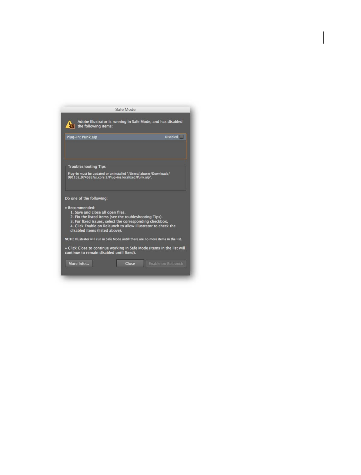
Safe Mode is a new feature that enables Illustrator to launch even if there are fatal, crash-inducing files (for example,
corrupt fonts, out-of-date plug-ins, or incorrect drivers) in the system. You can choose to diagnose the cause of the
error. When the application starts after isolating and disabling crash-causing files, Illustrator is in Safe Mode.
3
The Safe Mode dialog provides you with information to diagnose and troubleshoot the problem area, thus providing
you with a way to fix any issues. When done, mark all issues resolved and enable Illustrator to relaunch in normal mode
at the next restart.
For more information, see Safe Mode.
Recover data in your files
Forgetting to periodically save your open projects can cause you to lose time and work if an improper shutdown
happens before you could save your files. An improper shutdown could be Illustrator crashing, an operating system
error, or a power outage.
When such an error occurs, simply relaunch Illustrator and your work can be restored. If the cause of error is a damaged
font or incompatible driver or plug-in, Illustrator provides you with options to diagnose the issue and fix any errors.
For more information, see the article on Recover document data after a crash.
Last updated 6/5/2015
Page 10
What's new
Integration with Creative Cloud mobile apps
Illustrator no longer requires you to be at your studio or office to be creative and productive. Keep your ideas,
discoveries, and thoughts constantly evolving and rapidly developing into awesome artwork and projects – all while onthe-go – using Adobe’s mobile apps. A few examples:
Adobe Comp CC. Pull creative assets into Comp from your or your team’s shared Creative Cloud Libraries, then
instantly send your layouts to Illustrator. All your text, images, and graphics are live and fully editable.
Comp for iPad is available as a free download through the iTunes App Store.
Illustrator Draw. Create with your favorite vector drawing tools and features in a streamlined, modern interface.
You can draw lines, shapes, and free-form illustrations and with ten drawing layers and a photo layer. Creative
Cloud connectivity makes it easy to apply finishing touches in Illustrator CC or Photoshop CC.
Draw for iOS (iPhone, iPad, and iPad Mini) is available as a free download through the iTunes App Store
Adobe Shape CC. Photograph any object, design, or shape - and convert them into vector shapes in a few simple
steps. Store the resulting vectors in your Creative Cloud Libraries, and access them or refine them in Illustrator or
Photoshop.
Shape is available as a free download through the iTunes App Store and Google Play.
4
Adobe Brush CC. Use your iPad or iPhone to design beautiful, high-quality brushes from photos of anything that
inspires you. Save the brushes to your Creative Cloud Library and access them anywhere across Photoshop and
Illustrator!
Adobe Brush for iOS is available as a free download through the iTunes App Store and Google Play.
Adob
e Color. Capture inspiring color combinations wherever you see them, in a fun and intuitive way. Simply
point the camera at something colorful and Adobe Color CC will instantly extract a series of colors.
Color for iOS (iPad, iPad Mini, iPhone, and iPod Touch) and Android is available as a free download through the
iTunes App Store and Google Play.
Last updated 6/5/2015
Page 11

What's new
Creative Cloud Charts (Preview)
5
Create graphs and c
Illustrator vector graphics, and generate custom infographics, charts, and graphs. Use the browser-based interface to
quickly import data from your data files (.csv, .xls, .xlsx type files) and transform it into graphical representations. Use
Creative Cloud Libraries to share and use charts across projects and teams.
For more information, see Creative Cloud Charts (Preview).
Note: Th
users.
e Creative Cloud Charts (Preview) feature is enabled for all US (en_US) and UK (en_GB) Illustrator CC 2015
harts from your data, using a simple, intuitive interface. Replace the default chart elements with
GPU Performance
The 2015 release of Illustrator CC now better leverages the power of GPU to render content — which means faster
artw ork rend ering during zo oming, pann ing, and sc roll ing. Ea ch art type has be en rewritten, so that it is computed and
rendered on the graphic processor. GPU enhancements are now available for Macs as well.
For more information, see the knowledgebase article on GPU Performance feature .
Touch workspace enhancements
Image Place You can now place an image (raster format) in the Touch workspace.
Distribute Options in Align Panel Previously, the Align panel did not have distribute options. Now, users can use the
two most popular align options from the align panel in the Touch workspace.
Tools reset Some t ool s in the Touch wo rkspa ce h ave opti ons lik e Draw from C ent er i n Shap e Tools, Merge a nd Subtr act
Mode in Shap e Builde r. When sw itc hing bet ween tools , one often forgot that an opti on wa s enabled w hen the same tool
was used previously. This affected productivity. Now, whenever there is a change of tools in the Touch workspace, the
active tool becomes available with the default settings.
Flip buttons for Variable Width S
paths, to make them look organic. Variable-width profiles are based on an arbitrary direction (one end - thin, the other
- thick). With the introduction of Flip buttons for these profiles, you now have better control on variable-width profiles
they use on paths in the Touch workspace
troke options in the Touch workspace have a way to apply variable-width profiles to
Last updated 6/5/2015
Page 12

What's new
Tool enhancements
Curvature tool
Separate Rubber-banding Preference Rubber-banding preferences for the Pen and Curvature tools were tied to one
single value. The Illustrator team found that users preferred this value for the Curvature tool than for the Pen tool. Now,
both tools have separate values so that users have independent control over both tools.
Joining two paths The Curvature tool only worked with one path at a time - the active path. Now it is possible to join
a non-active path and continue working with it.
Start from either ends The Curvature tool had a fixed direction of working - even when a path was deselected and
reselected. Now for any open path, users can pick which end of the path to start working with. To be able to draw from
the other end-point, click and move the end-point slightly, and then continue drawing with the Curvature tool.
Shape Builder Tool: free-form Mode
The Shape Builder tool previously had linear feedback for Merge and Subtract options. Now, this tool can be used in
free-form mode. This mode is on by default. To get back to older, straight-line feedback, change the option in the tool's
options dialog. This is available in the Touch workspace as well.
6
Pencil Tool: Turn off auto-close
Although most users loved auto-close in Pencil Tool, there were some users who required path closure to occur at their
own discretion. The Pencil tool options dialog now has an option to control auto-closing.
Other important enhancements
Copy-paste hexadecimal values
When copying a hexadecimal value from other applications, users most likely pick the '#' symbol with the actual
hexadecimal value. The Hex field in Color panel only accepts pure hexadecimal values, and repeated, precise copypaste actions are required until only the right value is pasted. Now, this field automatically removes pasted characters
that are not part of the hexadecimal value. This makes it much easier to bring in hexadecimal values using a copy-paste
workflow.
Used Swatches on gradient stops
There are times when gradient stops are defined by a swatch color. Previously, it was not possible to identify this swatch
when the Color Stop was double-clicked. Now, if a color swatch is used on the Color Stop, it retains the information
and highlights the swatch used when the Color Stop is accessed.
Copy-paste patterns
Patterns are based on tile origins that are specific to the document. So, even with the 'Transform Patterns' option on,
copy-pasting objects filled with patterns used to show a different tiling pattern if the document size was different. Now,
with this option on, the appearance of a pattern will be same irrespective of the document size the pattern is pasted in.
Last updated 6/5/2015
Page 13

Chapter 2: Workspace
Workspace basics
Workspace overview
You create and manipulate your documents and files using various elements, such as panels, bars, and windows. Any
arrangement of these elements is called a workspace. The workspaces of the different applications in Creative Cloud
look similar so that you can move between the applications easily. You can also adapt each application to the way you
work by selecting from several preset workspaces or by creating one of your own.
Although the default workspace layout varies in different products, you manipulate the elements much the same way
in all of them.
7
• The Application bar across the top contains a workspace switcher, menus (Windows only), and other application
controls. On the Mac for certain products, you can show or hide it using the Window menu.
• The Tools panel contains tools for creating and editing images, artwork, page elements, and so on. Related tools are
grouped.
• The Control panel displays options for the currently selected tool. In Illustrator, the Control panel displays options
for the currently selected object. (In Adobe Photoshop® this is known as the Options bar. In Adobe Flash®, Adobe
Dreamweaver®, and Adobe Fireworks® this is known as the Property Inspector and includes properties of the
currently selected element.)
• The Document window displays the file you’re working on. Document windows can be tabbed and, in certain cases,
grouped and docked.
• Panels help you monitor and modify your work. Examples include the Timeline in Flash, the Brush panel in
Illustrator, the Layers panel in Adobe Photoshop®, and the CSS Styles panel in Dreamweaver. Panels can be grouped,
stacked, or docked.
• The Application frame groups all the workspace elements in a single, integrated window that lets you treat the
application as a single unit. When you move or resize the Application frame or any of its elements, all the elements
within it respond to each other so none overlap. Panels don’t disappear when you switch applications or when you
accidentally click out of the application. If you work with two or more applications, you can position each
application side by side on the screen or on multiple monitors.
If you are using a Mac and prefer the traditional, free-form user interface, you can turn off the Application frame.
In Adobe Illustrator®, for example, select Window > Application Frame to toggle it on or off. (In Flash, the
Application frame is on permanently for Mac, and Dreamweaver for Mac does not use an Application frame.)
Last updated 6/5/2015
Page 14
Workspace
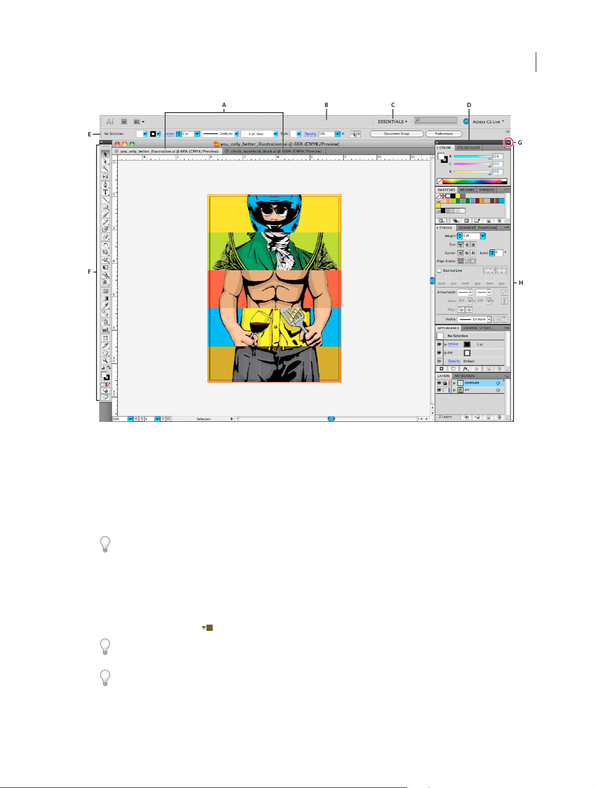
8
A Tabb ed D ocume nt w i ndows B Application bar C Workspace switcher D Panel title bar E Control panel F Too l s pan el G Collapse To Icons
button H
Four panel groups in vertical dock
Hide or show all panels
• (Illustrator, Adobe InCopy®, Adobe InDesign®, Photoshop, Fireworks)To hide or show all panels, including the Tools
panel and Control panel, press Tab.
• (Illustrator, InCopy, InDesign, Photoshop) To hide or show all panels except the Tools panel and Control panel,
press Shift+Tab.
Ti p: You can temporarily display hidden panels if Auto-Show Hidden Panels is selected in Interface preferences. It’s
always on in Illustrator. Move the pointer to the edge of the application window (Windows®) or to the edge of the
monitor (Mac OS®) and hover over the strip that appears.
• (Flash, Dreamweaver, Fireworks) To hide or show all panels, press F4.
Display panel options
❖ Click the panel menu icon in the upper-right corner of the panel.
Ti p: You can open a panel menu even when the panel is minimized.
Ti p: In Photoshop, you can change the font size of the text in panels and tool tips. In the Interface preferences, choose
a size from the UI Font Size menu.
Last updated 6/5/2015
Page 15

Workspace
(Illustrator) Adjust panel brightness
❖ In User Interface preferences, move the Brightness slider. This control affects all panels, including the Control panel.
Reconfigure the Tools panel
You can display the tools in the Tools panel in a single column, or side by side in two columns. (This feature is not
available in the Tools panel in Fireworks and Flash.)
In InDesign and InCopy, you also can switch from single-column to double-column (or single-row) display by setting
an option in Interface preferences.
❖ Click the double arrow at the top of the Tools panel.
Search For Help box
Use the Search For Help box on the right side of the Application bar to search for Help topics and online content. If you
have an active Internet connection, you can access all content on the Community Help website. If you search for Help
without an active Internet connection, search results are limited to Help content that is included with Illustrator.
1 In the search box, type the name of the item on which you want to search (such as a feature, application, or tool).
2 Press Enter.
9
All topics available from the Community Help center appear in a separate browser window.
About screen modes
You can change the visibility of the illustration window and menu bar using the mode options at the bottom of the Tools
panel. To access panels when in Full Screen Mode, position the cursor at the left or right edge of the screen and the
panels will pop up. If you’ve moved them from their default locations, you can access them from the Window menu.
You can choose one of the following modes:
• Normal Screen Mode displays artwork in a standard window, with a menu bar at the top and scroll bars on the
sides.
• Full Screen Mode With Menu Bar displays artwork in a full-screen window, with a menu bar at the top and scroll
bars.
• Full Screen Mode displays artwork in a full-screen window, with no title bar or menu bar.
Using the status bar
The status bar appears at the lower-left edge of the illustration window. It displays any of the following:
• current zoom level
• current tool in use
• current artboard in use
• navigation controls for multiple artboards
• date and time
• number of undos and redos available
• document color profile
• status of a managed file
Last updated 6/5/2015
Page 16
Workspace
Click the status bar to do any of the following:
• Change the type of information displayed in the status bar by selecting an option from the Show submenu.
• Show the current file in Adobe Bridge by choosing Reveal In Bridge.
Enter values in panels and dialog boxes
You enter values using the same methods in all panels and dialog boxes. You can also perform simple math in any box
that accepts numeric values. For example, if you want to move a selected object 3 units to the right using the current
measurement units, you don’t have to work out the new horizontal position—simply type +3 after the current value in
the Transform panel.
Enter a value in a panel or dialog box
❖ Do any of the following:
• Type a value in the box, and press Enter or Return.
• Drag the slider.
• Drag the dial.
• Click the arrow buttons in the panel to increase or decrease the value.
• Click in the box and then use the Up Arrow key and Down Arrow key on the keyboard to increase or decrease
the value. Hold down Shift and click an arrow key to magnify the increase rate or decrease rate.
10
• Select a value from the menu associated with the box.
Calculate values in a panel or dialog box
1 In a text box that accepts numerical values, do one of the following:
• To replace the entire current value with a mathematical expression, select the entire current value.
• To use the current value as part of a mathematical expression, click before or after the current value.
2 Type a simple mathematical expression using a single mathematical operator, such as + (plus), - (minus), x
(multiplication), / (division), or % (percent).
For example, 0p0 + 3 or 5mm + 4. Similarly, 3cm * 50% equals 3 centimeters multiplied by 50%, or 1.50 cm, and
50pt + 25% equals 50 points plus 25% of 50 points, or 62.5 points.
3 Press Enter or Return to apply the calculation.
Last updated 6/5/2015
Page 17

Workspace
Control panel overview
The Control panel offers quick access to options related to the objects you select. By default, the Control panel is docked
at the top of the workspace.
Options displayed in the Control panel vary depending on the type of object or tool you select. For example, when you
select a text object, the Control panel displays text-formatting options in addition to options for changing the color,
placement, and dimensions of the object. When a selection tool is active, you can access Document Setup and
Preferences from the Control panel.
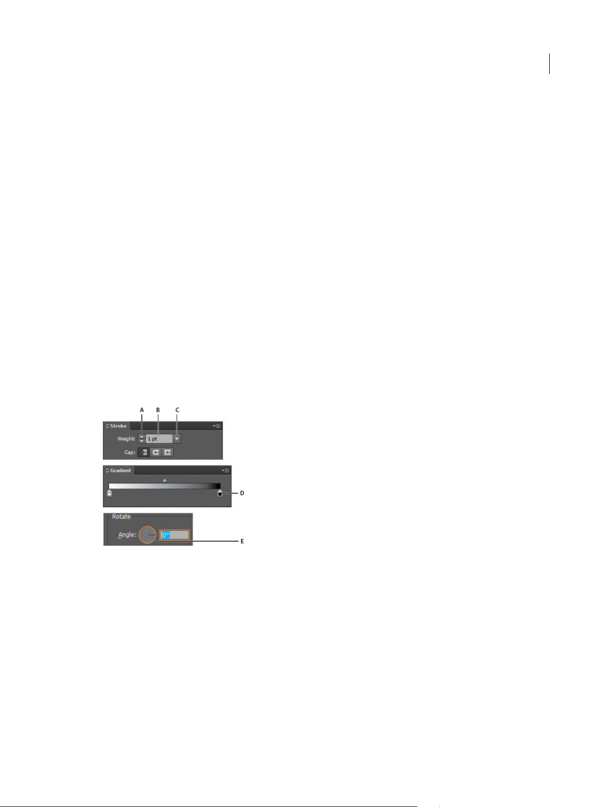
A Hidden options B Link to another panel C Panel menu
When text in the Control panel is blue and underlined, you can click the text to display a related panel or dialog box.
For example, click the word Stroke to display the Stroke panel.
Change the kinds of controls that appear in the Control panel
❖ Select or deselect options in the Control panel menu.
11
Open and close a panel or dialog box from the Control panel
1 Click a blue underlined word to open its associated panel or dialog box.
2 Click anywhere outside of the panel or dialog box to close it.
Dock the Control panel at the bottom of the workspace
❖ Choose Dock To Bottom from the Control panel menu.
Convert the Control panel to a floating panel
❖ Drag the gripper bar (located on the left edge of the panel) away from its current position.
To redock the Control panel, drag the gripper bar to the top or bottom of the application window (Windows) or
screen (Mac OS).
More Help topics
Work wit h A d o b e Br i d ge
Customizing the workspace
Customizing the workspace
Manage windows and panels
You can create a custom workspace by moving and manipulating Document windows and panels. You can also save
workspaces and switch among them. For Fireworks, renaming custom workspaces can lead to unexpected behavior.
Last updated 6/5/2015
Page 18
Workspace
Note: The following examples use Photoshop for demonstration purposes. The workspace behaves the same in all the
products.
Rearrange, dock, or float document windows
When you open more than one file, the Document windows are tabbed.
• To rearrange the order of tabbed Document windows, drag a window’s tab to a new location in the group.
• To undock (float or untab) a Document window from a group of windows, drag the window’s tab out of the group.
note: In Photoshop you can also choose Window > Arrange > Float in Window to float a single Document window, or
Window > Arrange > Float All In Windows to float all of the Document windows at once. See tech note
more information.
note: Dreamweaver does not support docking and undocking Document windows. Use the Document window’s
Minimize button to create floating windows (Windows), or choose Window > Tile Vertically to create side-by-side
Document windows. Search “Tile Vertically” in Dreamweaver Help for more information on this topic. The workflow
is slightly different for Macintosh users.
• To dock a Document window to a separate group of Document windows, drag the window into the group.
• To create groups of stacked or tiled documents, drag the window to one of the drop zones along the top, bottom, or
sides of another window. You can also select a layout for the group by using the Layout button on the Application bar.
note: Some products do not support this functionality. However, your product may have Cascade and Tile commands
in the Window menu to help you lay out your documents.
kb405298 for
12
• To switch to another document in a t abbed group when dragging a selection, drag the selection over the document’s
tab for a moment.
note: Some products do not support this functionality.
Dock and undock panels
A dock is a collection of panels or panel groups displayed together, generally in a vertical orientation. You dock and
undock panels by moving them into and out of a dock.
• To dock a panel, drag it by its tab into the dock, at the top, bottom, or in between other panels.
• To dock a panel group, drag it by its title bar (the solid empty bar above the tabs) into the dock.
• To remove a panel or panel group, drag it out of the dock by its tab or title bar. You can drag it into another dock or
make it free-floating.
Last updated 6/5/2015
Page 19
Workspace
You can prevent panels from filling all the space in a dock. Drag the bottom edge of the dock up so it no longer meets
the edge of the workspace.
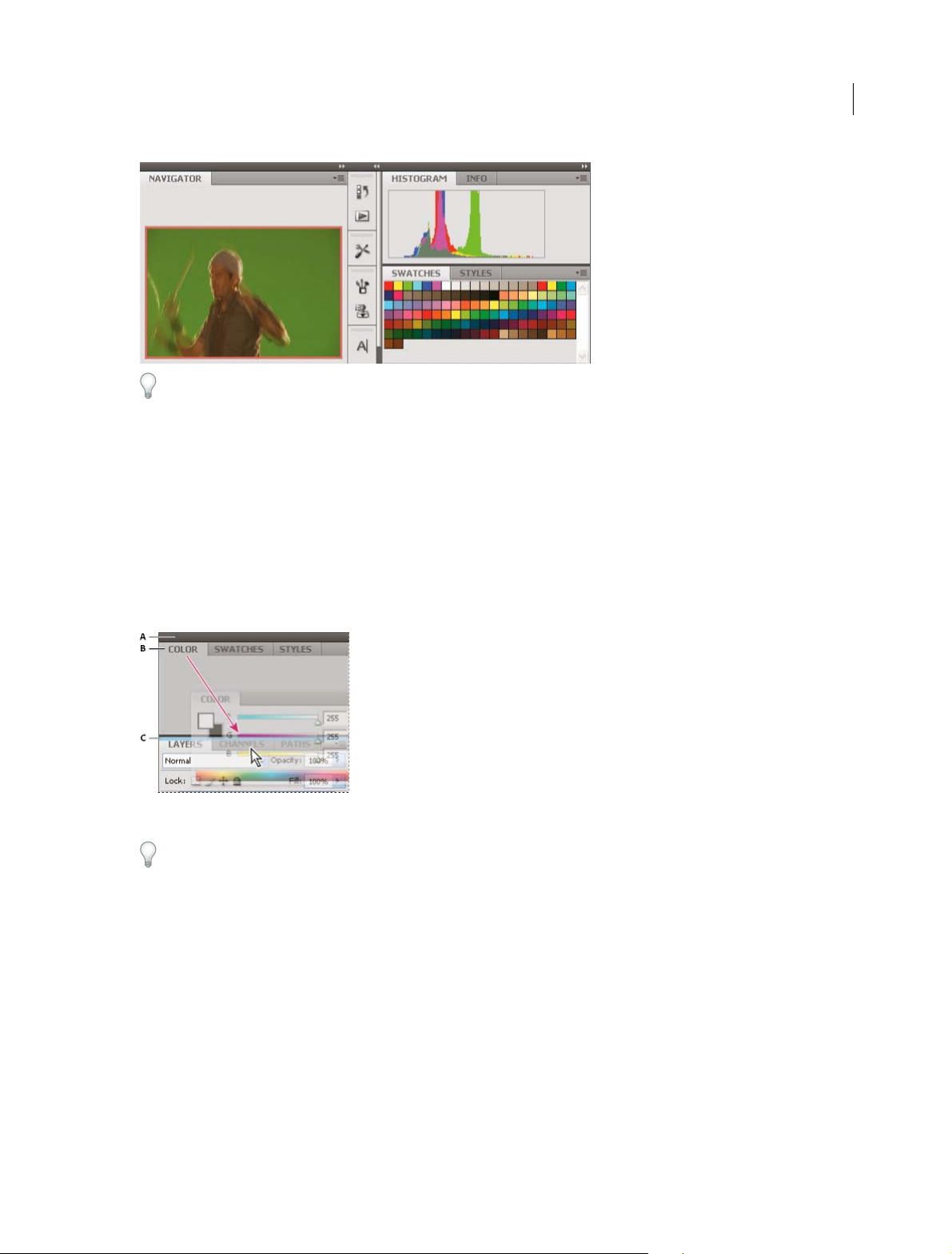
Move panels
As you move panels, you see blue highlighted drop zones, areas where you can move the panel. For example, you can
move a panel up or down in a dock by dragging it to the narrow blue drop zone above or below another panel. If you
drag to an area that is not a drop zone, the panel floats freely in the workspace.
Note: The position of the mouse (rather than the position of the panel), activates the drop zone, so if you can’t see the drop
zone, try dragging the mouse to the place where the drop zone should be.
13
• To move a panel, drag it by its tab.
• To move a panel group, drag the title bar.
A Title bar B Tab C Drop zone
Press Ctrl (Windows) or Command (Mac OS) while moving a panel to prevent it from docking. Press Esc while moving
the panel to cancel the operation.
Add and remove panels
If you remove all panels from a dock, the dock disappears. You can create a dock by moving panels to the right edge of
the workspace until a drop zone appears.
• To remove a panel, right-click (Windows) or Control-click (Mac) its tab and then select Close, or deselect it from
the Window menu.
• To add a panel, select it from the Window menu and dock it wherever you want.
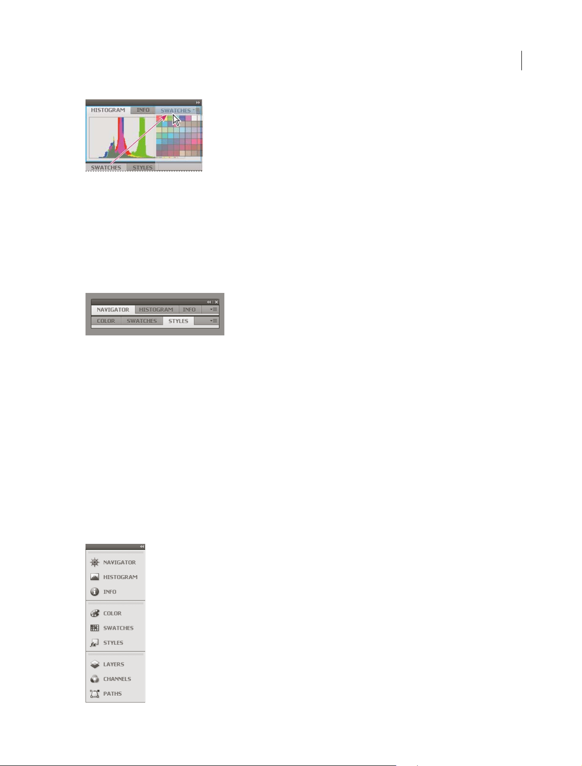
Manipulate panel groups
• To move a panel into a group, drag the panel’s tab to the highlighted drop zone in the group.
Last updated 6/5/2015
Page 20
Workspace
• To rearrange panels in a group, drag a panel’s tab to a new location in the group.
• To remove a panel from a group so that it floats freely, drag the panel by its tab outside the group.
• To move a group, drag the title bar (the area above the tabs).
Stack floating panels
When you drag a panel out of its dock but not into a drop zone, the panel floats freely. The floating panel allows you to
position it anywhere in the workspace. You can stack floating panels or panel groups so that they move as a unit when
you drag the topmost title bar.
14
• To stack floating panels, drag a panel by its tab to the drop zone at the bottom of another panel.
• To change the stacking order, drag a panel up or down by its tab.
note: Be sure to release the tab over the narrow drop zone between panels, rather than the broad drop zone in a title bar.
• To remove a panel or panel group from the stack, so that it floats by itself, drag it out by its tab or title bar.
Resize panels
• To minimize or maximize a panel, panel group, or stack of panels, double-click a tab. You can also double-click the
tab area (the empty space next to the tabs).
• To resize a panel, drag any side of the panel. Some panels, such as the Color panel in Photoshop, cannot be resized
by dragging.
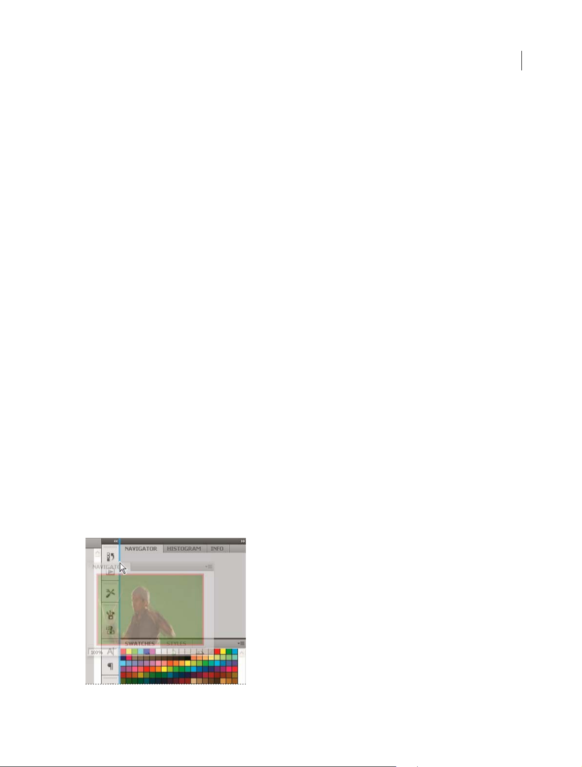
Collapse and expand panel icons
You can collapse panels to icons to reduce clutter on the workspace. In some cases, panels are collapsed to icons in the
default workspace.
Last updated 6/5/2015
Page 21
Workspace
• To collapse or expand all panel icons in a column, click the double arrow at the top of the dock.
• To expand a single panel icon, click it.
• To resize panel icons so that you see only the icons (and not the labels), adjust the width of the dock until the text
disappears. To display the icon text again, make the dock wider.
• To collapse an expanded panel back to its icon, click its tab, its icon, or the double arrow in the panel’s title bar.
Ti p: In some products, if you select Auto-Collapse Icon Panels from the Interface or User Interface Options
preferences, an expanded panel icon collapses automatically when you click away from it.
• To add a floating panel or panel group to an icon dock, drag it in by its tab or title bar. (Panels are automatically
collapsed to icons when added to an icon dock.)
• To move a panel icon (or panel icon group), drag the icon. You can drag panel icons up and down in the dock, into
other docks (where they appear in the panel style of that dock), or outside the dock (where they appear as floating
icons).
15
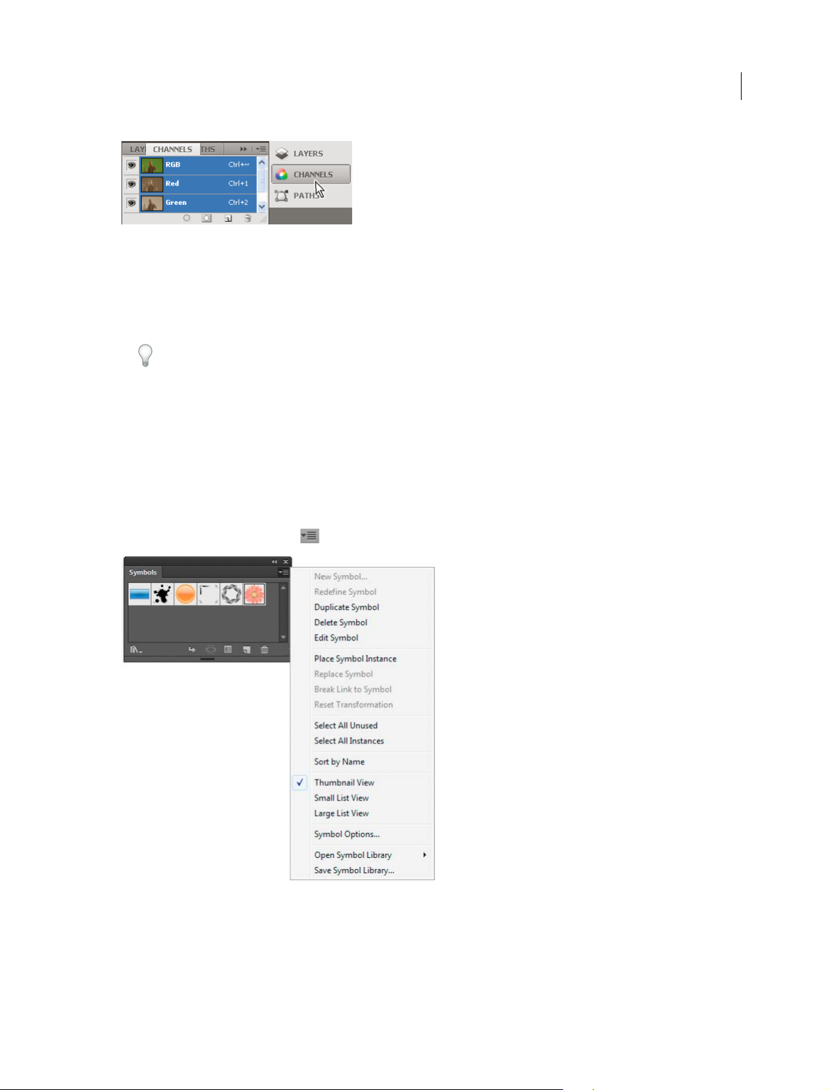
Use panel menus
Access the panel menus using the icon on the upper-right corner of the panel.
Rename or duplicate a workspace
1 Choose Window > Workspace > Manage Workspaces.
2 Do any of the following, and then click OK:
• To rename a workspace, select it, and edit the text.
Last updated 6/5/2015
Page 22

Workspace
• To duplicate a workspace, select it, and click the New button.
For a video on customizing the workspace based on different workflows, see www.adobe.com/go/vid0032_en.
Save and switch workspaces
By saving the current size and position of panels as a named workspace, you can restore that workspace even if you
move or close a panel. The names of saved workspaces appear in the workspace switcher in the Application bar.
Save a custom workspace
1 With the workspace in the configuration you want to save, do one of the following:
• (Illustrator) Choose Window > Workspace > Save Workspace.
• (Photoshop, InDesign, InCopy) Choose Window > Workspace > New Workspace.
• (Dreamweaver) Choose Window > Workspace Layout > New Workspace.
• (Flash) Choose New Workspace from the workspace switcher in the Application bar.
• (Fireworks) Choose Save Current from the workspace switcher in the Application bar.
2 Type a name for the workspace.
3 (Photoshop, InDesign) Under Capture, select one or more options:
Panel Locations Saves the current panel locations (InDesign only).
16
Keyboard shortcuts Saves the current set of keyboard shortcuts (Photoshop only).
Menus or Menu Customization Saves the current set of menus.
Display or switch workspaces
❖ Select a workspace from the workspace switcher in the Application bar.
In Photoshop, you can assign keyboard shortcuts to each workspace to navigate among them quickly.
Delete a custom workspace
• Select Manage Workspaces from the workspace switcher in the Application bar, select the workspace, and then click
Delete. (The option is not available in Fireworks.)
• (Photoshop, InDesign, InCopy) Select Delete Workspace from the workspace switcher.
• (Illustrator) Choose Window > Workspace > Manage Workspaces, select the workspace, and then click the Delete
icon.
• (Photoshop, InDesign) Choose Window > Workspace >Delete Workspace, select the workspace, and then click
Delete.
Restore the default workspace
1 Select the Default or Essentials workspace from the workspace switcher in the application bar. For Fireworks, see
the article
Note: In Dreamweaver, Designer is the default workspace.
http://www.adobe.com/devnet/fireworks/articles/workspace_manager_panel.html.
2 For Fireworks (Windows), delete these folders:Wi n do w s
Vista\\Users\<username>\AppData\Roaming\Adobe\Fireworks CS4\ Windows XP\\Documents and
Settings\<username>\Application Data\Adobe\Fireworks CS4
Last updated 6/5/2015
Page 23

Workspace
3 (Photoshop, InDesign, InCopy) Select Window > Workspace > Reset [Workspace Name].
(Photoshop) Restore a saved workspace arrangement
In Photoshop, workspaces automatically appear as you last arranged them, but you can restore the original, saved
arrangement of panels.
• To restore an individual workspace, choose Window > Workspace > Reset Wor k s p a c e Name.
• To restore all the workspaces installed with Photoshop, click Restore Default Workspaces in the Interface
preferences.
To rearrange the order of workspaces in the application bar, drag them.
To ols
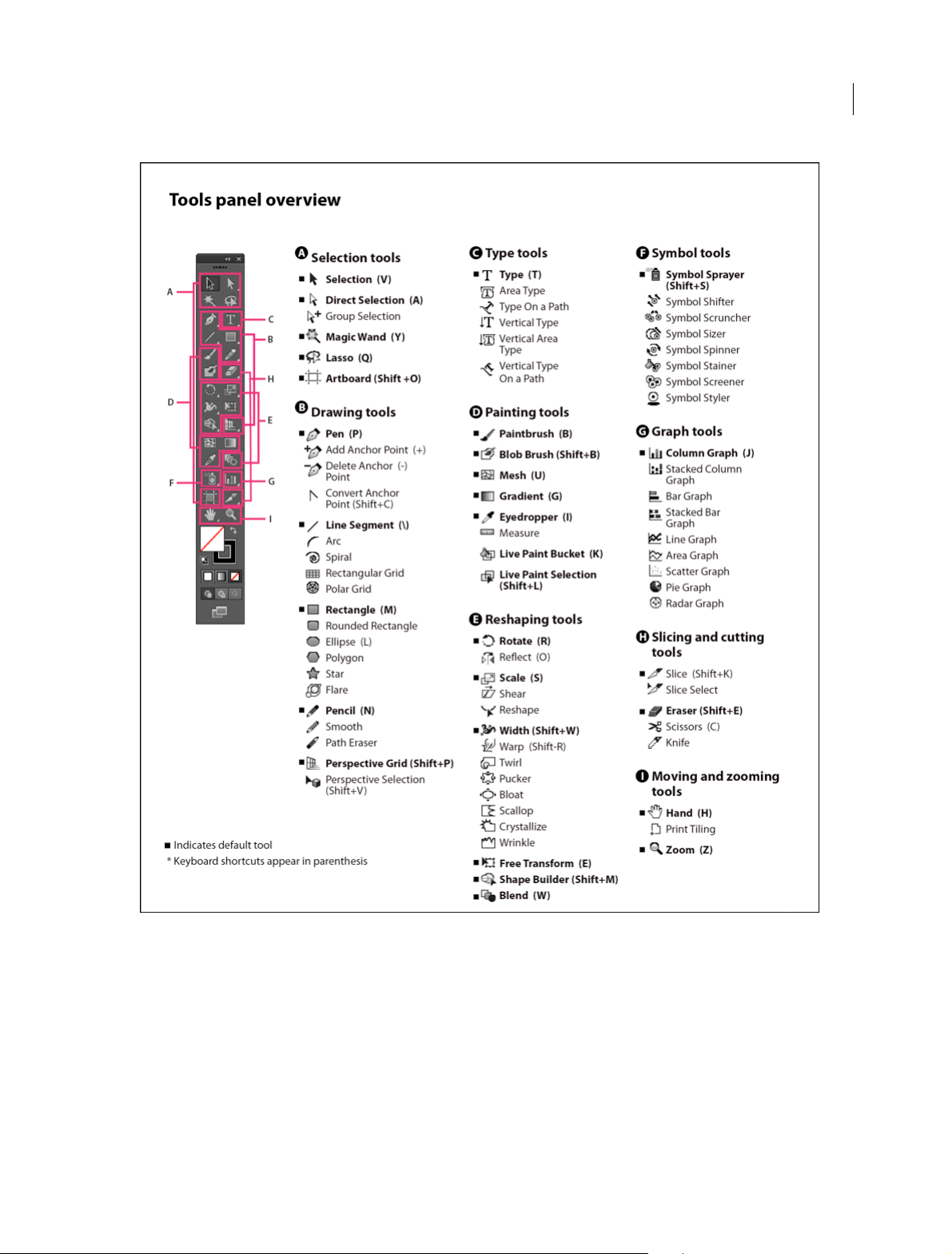
Tools pan el overview
The first time you start the application, the Tools panel appears at the left side of the screen. You can move the Tools
panel by dragging its title bar. You can also show or hide the Tools panel by choosing Window > Tools.
17
You use tools in the Tools panel to create, select, and manipulate objects in Illustrator. Some tools have options that
appear when you double-click a tool. These include tools that let you use type, and select, paint, draw, sample, edit, and
move images.
You can expand some tools to show hidden tools beneath them. A small triangle at the lower-right corner of the tool
icon signals the presence of hidden tools. To see the name of a tool, position the pointer over it.
You can also use the Tools panel to change the drawing mode from Draw Normal to Draw Behind or Draw Inside.
Last updated 6/5/2015
Page 24
Workspace
18
View hidden tools
❖ Hold down the mouse button on the visible tool.
View tool options
❖ Double-click a tool in the Tools panel.
Move the Tools panel
❖ Drag its title bar.
Last updated 6/5/2015
Page 25
Workspace
View the Tools panel in double-stack or single-column
❖ Click the double-arrow on the title bar to toggle between double-stack and single-column view of the Tools panel.
Hide the Tools panel
❖ Choose Window > Tools.
Tear off hidden tools into a separate panel
❖ Drag the pointer over the arrow at the end of the hidden tools panel and release the mouse button.
Close a separate tool panel
❖ Click the close button on the panel’s title bar. The tools return to the Tools panel.
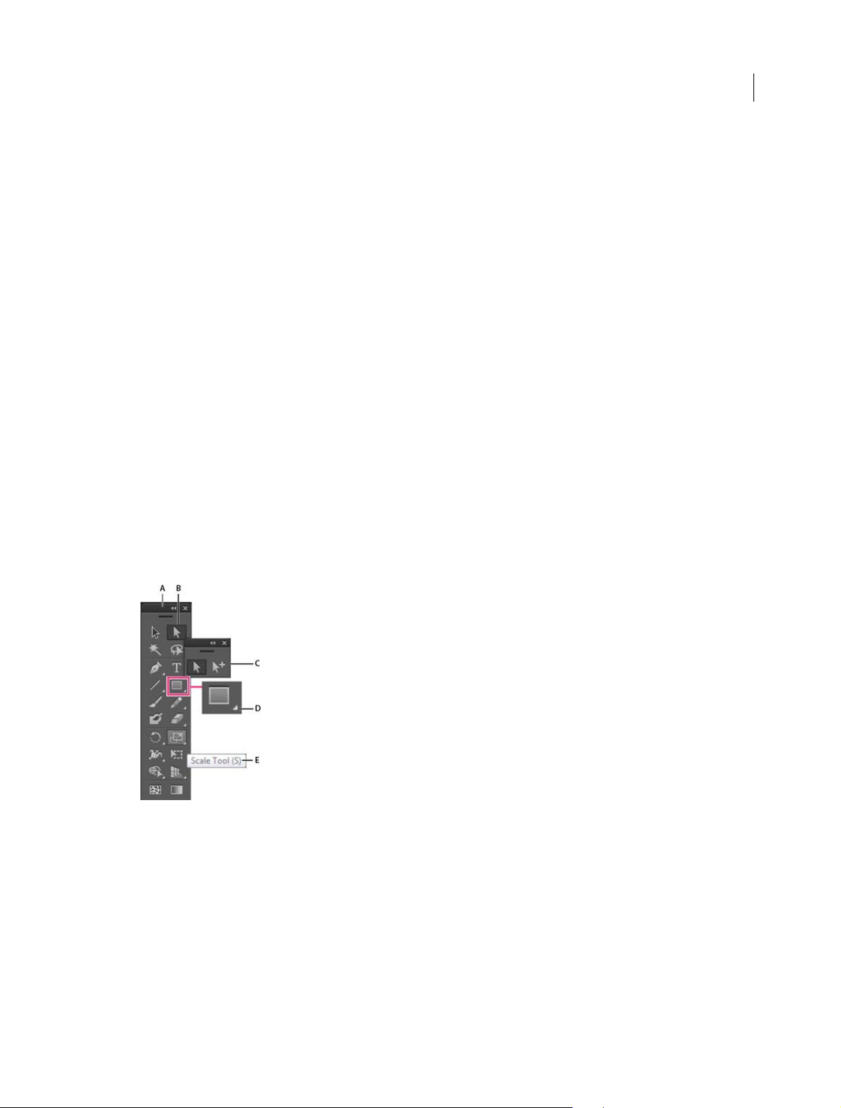
Select a tool
❖ Do one of the following:
• Click a tool in the Tools panel. If there is a small triangle at a tool’s lower-right corner, hold down the mouse
button to view the hidden tools, and then click the tool you want to select.
• Hold down Alt (Windows) or Option (Mac OS), and then click a tool to cycle through and select hidden tools.
• Press the tool’s keyboard shortcut. The keyboard shortcut is displayed in its tool tip. For example, you can select
the Move tool by pressing the V key.
Ti p: To hide tool tips, choose Edit > Preferences > General (Windows) or Illustrator > Preferences > General
(Mac OS), and deselect Show Tool Tips.
19
A Tools panel B Active tool C Tear off panel with hidden tools D Hidden tool triangle E Tool name and shortcut
Change tool pointers
The mouse pointer for most tools matches the tool’s icon. Each pointer has a different hotspot, where an effect or action
begins. With most tools, you can switch to precise cursors, which appear as cross hairs centered around the hotspot,
and provide for greater accuracy when working with detailed artwork.
❖ Choose Edit > Preferences > General (Windows) or Illustrator > Preferences > General (Mac OS), and select Use
Precise Cursors. Alternatively, press Caps Lock on the keyboard.
More Help topics
Tool g a l le r i es
Last updated 6/5/2015
Page 26
Workspace
Tool galleries
Illustrator provides many tools for creating and manipulating your artwork. These galleries provide a quick visual
overview for each tool.
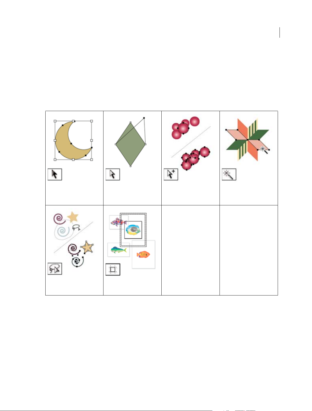
Selection tool gallery
Illustrator provides the following selection tools:
20
The Selection tool ( V) selects entire
objects. See Select objects with the
Selection tool.
The Lasso tool (Q) selects points or
path segments within objects. See
Select objects with the Lasso tool.
The Direct Selection tool (A) selects
points or path segments within
objects. See Select paths, segments,
and anchor points.
The Artboard tool creates separate
artboards for printing or export.
Create an artboard.
See
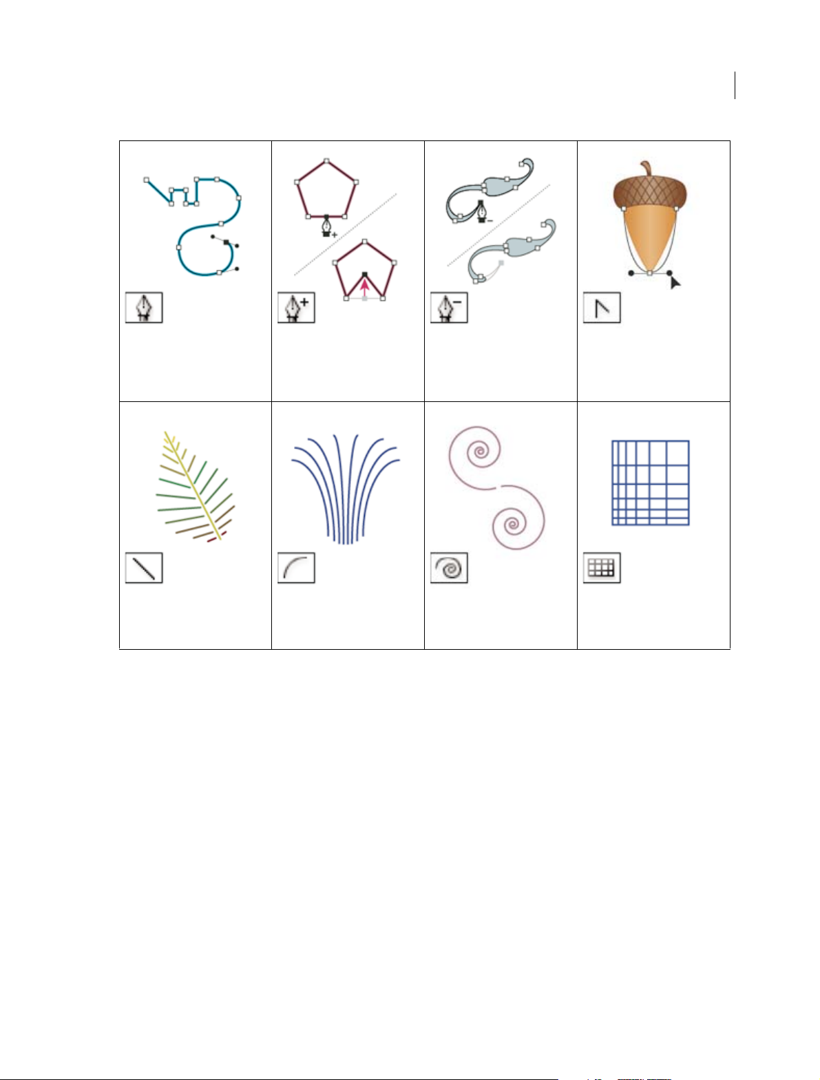
Drawing tool gallery
Illustrator provides the following drawing tools:
The Group Selection tool selec ts
objects and groups within groups.
See Select objects and groups with
the Group Selection tool.
The Magic Wand tool (Y) selects
objects with similar attributes. See
Select objects with the Magic Wand
tool.
Last updated 6/5/2015
Page 27
Workspace
21
The Pen tool (P) draws straight and
curved lines to create objects. See
Drawing with the Pen tool.
The Line Segment tool (\) draws
individual straight line segments.
See Draw straight lines with the
Line Segment tool.
The Add Anchor Point tool (+) adds
anchor points to paths. See
and deleting anchor points.
The Arc tool draws individual
concave or convex curve segments.
See Draw arcs.
Adding
The Delete Anchor Point tool (-)
deletes anchor points from paths.
See Adding and deleting anchor
points.
The Spiral tool draws clockwise and
counterclockwise spirals. See Draw
spirals.
The Convert Anchor Point tool
(Shift+C) changes smooth points to
corner points and vice versa. See
Convert between smooth points
and corner points.
The Rectangular Grid tool draws
rectangular grids. See Draw
rectangular grids.
Last updated 6/5/2015
Page 28
Workspace
22
The Polar Grid tool draws circular
chart grids. See Draw circular
(polar) grids.
The Polygon tool draws regular,
multi-sided shapes. See Draw
polygons.
The Rectangle tool (M) draws
squares and rectangles. See Draw
rectangles and squares.
The Star tool draws stars. See Draw
stars.
The Rounded Rectangle tool draws
squares and rectangles with
rounded corners. See Draw
rectangles and squares.
The Flare tool creates lens-flare or
solar-flare-like effects. See Drawing
flares.
The Ellipse tool (L) draws circles and
ovals. See Draw ellipses.
The Pencil tool (N) draws and edits
freehand lines. See Drawing with
the Pencil tool.
The Smooth tool smooths Bezier
paths. See
Smooth paths.
The Path Eraser tool erases paths
and anchor points from the object.
See
Erase artwork.
Type tool gallery
Illustrator provides the following type tools:
The Perspective Grid allows
creating and rendering artwork in
perspective. See
Grid.
Last updated 6/5/2015
About Perspective
The Perspective Selection to ol
allows you to bring objects, text,
and symbols in perspective, move
objects in perspective, move objects
in perpendicular to its current
direction. See
Grid..
About Perspective
Page 29
Workspace
23
The Type tool (T) creates individual
type and type containers and lets
you enter and edit type. See Enter
text in an area.
The Vertical Area Type tool changes
closed paths to vertical type
containers and lets you enter and
edit type within them. See Enter text
in an area.
The Area Type tool changes closed
paths to type containers and lets
you enter and edit type within
them. See Enter text in an area.
The Vertical Type On A Path tool
changes paths to vertical type
paths and lets you enter and edit
type on them. See Creating type on
a path .
Painting tool gallery
Illustrator provides the following painting tools:
The Type On A Path tool changes
paths to type paths, and lets you
enter and edit type on them. See
Creating type on a path .
The Vertical Type tool creates
vertical type and vertical type
containers and lets you enter and
edit vertical type. See Enter text in
an area.
Last updated 6/5/2015
Page 30
Workspace
24
The Paintbrush tool (B) draws
freehand and calligraphic lines, as
well as art, patterns, and bristle
brush strokes on paths. See Draw
paths and apply brush strokes
simultaneously.
The Live Paint Bucket tool (K) pa ints
faces and edges of Live Paint
groups with the current paint
attributes. See Paint with the Live
Paint Bucket tool.
The Mesh tool (U) creates and edits
meshes and mesh envelopes. See
Create mesh objects.
The Live Paint Selection (ShiftL)tool selects faces and edges
within Live Paint groups. See Select
items in Live Paint groups.
The Gradient tool (G) adjusts the
beginning and ending points and
angle of gradients within objects, or
applies a gradient to objects. See
Apply a gradient to an object.
The Measure tool measures the
distance between two points. See
Measure the distance between
objects.
The Eyedropper tool (I) samples and
applies color, type, and appearance
attributes, including effects, from
objects. See Copy appearance
attributes using the Eyedropper
tool.
The Blob Brush tool (Shift-B)draws
paths that automatically expand
and merge calligraphic brush paths
that share the same color and are
adjacent in stacking order. See
Draw and merge paths with the
Blob Brush tool.
Reshaping tool gallery
Illustrator provides the following tools for reshaping objects:
Last updated 6/5/2015
Page 31

Workspace
25
The Rotate tool (R) rotates objects
around a fixed point. See
objects.
Rotate
The Reflect tool (O) flips objects over
a fixed axis. See
objects.
Reflect or flip
The Scale tool (S) resizes objects
around a fixed point. See
objects.
Scale
The Shear tool skews objects
around a fixed point. See
objects with the Shear tool.
Shear
Last updated 6/5/2015
Page 32

Workspace
26
The Reshape tool adjusts selected
anchor points while keeping the
overall detail of the path intact. See
Stretch parts of a path without
distorting its overall shape.
The Warp tool (Shift+R) molds
objects with the movement of the
cursor (like molding clay, for
example). See
a liquify tool.
Distort objects using
The Free Transform tool (E) scales,
rotates, or skews a selection.
The Twirl tool creates swirling
distortions within an object. See
Distort objects using a liquify tool.
The Blend tool (W ) creates a series
of objects blended between the
color and shape of multiple objects.
See Create blends.
The Pucker tool deflates an object
by moving control points towards
the cursor. See Distort objects using
a liquify tool.
The Width tool (Shift+W) allows
you to create a stroke with variable
width. See
The Bloat tool inflates an object by
moving control points away from
the cursor. See Distort objects using
a liquify tool.
Using the Width tool.
The Scallop tool adds random
curved details to the outline of an
object. See Distort objects using a
liquify tool.
The Crystallize tool adds random
spiked details to the outline of an
object. See Distort objects using a
liquify tool.
Last updated 6/5/2015
The Wrinkle tool adds wrinkle-like
details to the outline of an object.
See Distort objects using a liquify
tool.
The Shape Builder tool merges
simple shapes to create custom,
complex shapes. See Building new
shapes using the Shape Builder tool
.
Page 33

Workspace
Symbolism tool gallery
The symbolism tools let you create and modify sets of symbol instances. You create a symbol set using the Symbol
Sprayer tool. You can then use the other symbolism tools to change the density, color, location, size, rotation,
transparency, and style of the instances in the set.
27
The Symbol Sprayer tool (Shift+S)
places multiple symbol instances as
a set on the artboard. See Create
symbol sets.
The Symbol Spinner tool rotates
symbol instances. See Rotate
symbol instances.
The Symbol Shifter tool moves
symbol instances and change
stacking order. See Change
stacking order of symbol instances
in a set.
The Symbol Stainer tool colorizes
symbol instances. See Stain symbol
instances.
The Symbol Scruncher tool moves
symbol instances closer together o r
farther apart. See Gather or scatter
symbol instances.
The Symbol Screener tool applies
opacity to symbol instances. See
Adjust transparency of symbol
instances.
The Symbol Sizer tool resizes
symbol instances. See Resize
symbol instances.
The Symbol Styler tool applies the
selected style to symbol instances.
Apply a graphic style to symbol
See
instances.
Graph tool gallery
Illustrator provides nine graph tools, each one for creating a different type of graph. The type of graph you choose
depends on the information you want to communicate. See
Create a graph.
Last updated 6/5/2015
Page 34

Workspace
29
The Column Graph tool (J) creates
graphs that compare values using
vertical columns.
The Line Graph tool creates graphs
that use points to represent one or
more sets of values, with a different
line joining the points in each set.
This type of graph is often used to
show the trend of one or more
subjects over a period of time.
The Stacked Column Graph tool
creates graphs that are similar to
column graphs, but stacks the
columns on top of one another,
instead of side by side. This graph
type is useful for showing the
relationship of parts to the total.
The Area Graph tool creates graphs
that are similar to line graphs, but
emphasizes totals as well as
changes in values.
The Bar Graph tool creates graphs
that are similar to column graphs,
but positions the bars horizontally
instead of vertically.
The Scatter Graph tool creates
graphs that plot data points as
paired sets of coordinates along the
x and y axes. Scatter graphs are
useful for identifying patterns or
trends in data. They also can
indicate whether variables affect
one another.
The Stacked Bar Graph tool creates
graphs that are similar to stacked
column graphs, but stacks the bars
horizontally instead of vertically.
The Pie Graph tool creates circular
graphs whose wedges represent the
relative percentages of the values
compared.
Last updated 6/5/2015
Page 35

Workspace
The Radar Graph tool creates
graphs that compare sets of values
at given points in time or in
particular categories, and is
displayed in a circular format. This
type of graph is also called a web
graph.
Moving and zooming tool gallery
Illustrator provides the following tools for moving around in and controlling the view of the artboard:
30
The Hand
tool (H) moves the Illustrator artboard within
the illustration window.
Tiling tool adjusts the page grid to control where
artwork appears on the printed page.
The Print
The Zoom
tool (Z) increases and decreases the view
magnification in the illustration window.
More Help topics
Keys for selecting
Improved User Interface
The new user interface framework leverages performance enhancements and advantages like native 64-bit support to
render a cleaner interface, enabling a better user experience. Also, important additions and modifications to the user
interface and workflows make working with Illustrator an efficient experience.
Last updated 6/5/2015
Page 36

Workspace
Improved and efficient user interface
Efficient and flexible interface. The newer usability enhancements enable you to use fewer clicks and fewer steps to
achieve routine or frequent actions. For example, in the Character panel (Ctrl+T), the font list displays names in the
font style itself. You can quickly pick the font of your choice from the list.
Inline editing. Easily work with Layers, Actions, Swatches, Symbols, and other panels, with the ability to edit object
names directly in the panel. You no longer need an additional modal dialog for such routine actions. For example,
double-click the name of a layer in the Layers panel to switch to inline editing mode. Type the new name and press
Enter.
31
Quick-edit object attributes. In the user interface, values of object attributes are set through drop-down lists or text
fields. You can now quickly edit these fields by hovering your mouse pointer over a control, and scrolling the mouse
wheel. For example, to increase or decrease the weight of a stroke, hover the mouse pointer over the stroke weight
control, and scroll.
Dialog boxes. Buttons to commit an action or event are placed uniformly at the lower-right corner. Dialog boxes also
have full keyboard access.
Wo rk s p ac e s . New workspaces are task-based. A workspace can now 'remember' the state it was last left in, and then be
reset to default settings when necessary.
New icons. Updated to enhance usability, newer icons contribute to a better, more intuitive interface.
Cursors. Modifications have been done to make cursors larger and more precise.
User interface color and brightness
Illustrator, by default, is now available with a dark theme, which is in line with recent changes in other products like
Adobe Photoshop. This theme enables a a more pleasant visual experience, especially while working with rich colors
and designs.
Last updated 6/5/2015
Page 37

Workspace
32
You can easily vary the brightness of the user interface to a tone you prefer from the User Interface tab in the Preferences
dialog (Ctrl + K). Enable the Match User Interface Brightness option to set the tone of the canvas area to match the
brightness of the interface. If you prefer the classic Illustrator canvas color, you can set it to default to white.
For more information, view the video on user interface enhancements, by Lynda.com.
Panels
Control panel. Object controls that are used frequently are grouped and displayed together in the Control panel.
Grouping controls in this manner helps you work with objects faster and more systematically.
Trans form pan e l. The Scale Strokes & Effects option has been included in the Transform panel and the Transform
Effect dialog.
Last updated 6/5/2015
Page 38

Workspace
Transparency panel. Masking features are now available in the Transparency panel. Use the Make Mask / Release
toggle switch to create opacity masks and work with them more easily.
33
Safe Mode
When you launch Adobe Illustrator, the necessary plug-ins, fonts, drivers, and other third-party elements that are
required to function properly are loaded. In the past, when Illustrator encountered an error, for example – a damaged
font, the application would crash and it was difficult to diagnose the cause of the problem.
Safe Mode is a new feature that:
• Enables Illustrator to start despite encountering fatal, crash-inducing fonts, plug-ins, or more.
• Determines the cause of a crash, prevents the particular file from loading with Illustrator, and provides a listing of
the problem-causing elements when Illustrator restarts
• Assists you in diagnosing and troubleshooting the problem-area, thus providing you with a way to fix any issues.
While running in Safe Mode, Illustrator functions normally, except that the disabled items will not be available for use
within Illustrator. For example, if a font has been found to be damaged, Illustrator will no longer display that font as an
available option to apply to text elements.
Safe Mode workflow
When you have crash-inducing elements in your Illustrator environment:
Last updated 6/5/2015
Page 39

Workspace
34
Using Safe Mode
Note: This procedure assumes, at Step 1, that Illustrator has been functioning normally until now.
1 Start Illustrator. If Illustrator detects a file that is corrupt or causes errors, the application exits.
2 Do one of the following:
• Windows: Re-launch Illustrator.
• Mac: Choose Reopen.
Last updated 6/5/2015
Page 40

Workspace
3 As Illustrator restarts, you can:
• Choose Run Diagnostics to switch Illustrator to Safe Mode, to help with troubleshooting the error.
• Choose Launch Illustrator to try to start Illustrator normally again.
4 (This step may repeat multiple times) Illustrator restarts. If an error is found, the cause of the error (font, driver,
plug-in) is identified and disabled from obstructing Illustrator launch.
35
Note: This step is repeated for each crash-inducing file that Illustrator finds. Do not interrupt diagnostic tests.
5 When all error-causing files have been isolated by the diagnostic steps and noted, Illustrator launches in Safe Mode.
6 When Illustrator starts, the Safe Mode dialog displays a list of all the plug-ins, fonts, or drivers that are causing
Illustrator to crash. Choose from Step 7 or Step 8.
Last updated 6/5/2015
Page 41

Workspace
36
7 (Option 1 of 2) To f i x e rr o r s :
a Click a row in the list.
b Check the Troubleshooting Tips area for information.
Last updated 6/5/2015
Page 42

Workspace
37
c Follow the tips provided and replace a font, or update a plug-in, or uninstall error-causing items, as preferred.
d If you believe the error has been fixed, select the checkbox available for each row.
e Click Enable on Re-launch, save your work, and restart Illustrator.
8 (Option 2 of 2). To continue in Safe Mode: In the Safe Mode dialog (Step 6), click Close to continue running in Safe
Mode. All error-causing files will continue to be disabled.
Note: At any point in time, click the Safe Mode link in the App Bar to see the Safe Mode dialog. Or, you can click Help >
Safe Mode, to use the Safe Mode dialog.
Recover document data after a crash
The Illustrator Data Recovery feature is useful in the event that Illustrator crashes and you have not saved your work
yet. The Data Recovery feature takes a snapshot of the file that you are working on at regular intervals, and ensures that
you never have to lose work due Illustrator crashes that may occur on account of operating system or application errors.
While restarting Illustrator after a crash, these three conditions may occur:
• If a Data Recovery snapshot is found, the file is opened with [Recovered] appended to the file name. You can choose
to save the file as the original, or under a new file name in the Save As dialog.
Last updated 6/5/2015
Page 43

Workspace
• If a Data Recovery snapshot is not found for a file that was open when Illustrator crashed (indicates no unsaved
information), the file is opened afresh and is available for editing.
• If no usable Data Recovery information is found for a file that was open when Illustrator crashed, the file is opened
in its last saved state, and is available for editing.
Configurable preferences
The preferences for the Data Recovery feature are available in the Preferences panel (Preferences > File Handling &
Clipboard > Data Recovery area).
• Automatically Save Recovery Data Every. Select the checkbox to turn the Data Recovery feature on.
• Interval. Select an appropriate duration from the Interval dropdown. Illustrator will s ave a backup at this frequency
in minutes.
• Folder / Choose: Displays and allows you to configure the location at which Illustrator stores backup files.
• Turn off Data Recovery for complex documents. Select the checkbox to prevent the Data Recovery feature from
slowing down while backing up complex files.
38
Important considerations
Turn off Data Recovery for complex documents (Preferences, Default: Off) When Data Recovery is turned on,
Illustrator may seem to pause while backing up larger files that contain byte-heavy raster images or need a considerable
time to backup. If this interrupts your workflow, you can choose to turn this setting on.
Last updated 6/5/2015
Page 44

Workspace
Data Recovery Interval (Preferences, Default: 2 minutes) Setting a time interval that is too short may tend interrupt
your flow as you work, especially if you are working on extremely large or complex files. However, setting too long a
time interval may increase the potential for data loss in the event of a crash. Use your discretion to set a value that works
best for you.
Illustrator crashes during a Data Recover y operation If Illustrator crashes while the Data Recovery operation is either
saving a snapshot or opening a recovered file, then the Data Recovery option is turned off automatically. To continue
using the Data Recovery feature, you must re-enable it from the Preferences panel (Ctrl/Cmd + K).
How Data Recovery works
1 You open an Illustrator file, and have enabled the Data Recovery feature to run through the Preferences Panel.
2 At regular time intervals, as specified in the Data Recovery preferences, Illustrator takes a snapshot of your open file
with your current edits.
3 Illustrator and/or the open file are closed under two conditions:
• You close the file or exit Illustrator. The recovery snapshot file is deleted.
• Illustrator encounters an unexpected condition and crashes. The snapshot is retained.
4 When you restart Illustrator, if there are recoverable files available, a prompt is displayed to indicate that files have
been recovered.
39
5 Data Recovery snapshot files are automatically opened. The file name for such files contains the text [Recovered].
For example, if the file being edited when Illustrator crashed was named logo_review.ai, the recovered file will be
named logo_review [Recovered].ai.
Note: The restored file contains data at the time the last automatic save was performed. Any actions performed between
an automatic save and application crash is not saved.
6 When you attempt to save the file, the Save As dialog is displayed. Choose to overwrite the file or save the file with
a different file name, and then continue working on it.
Touch Workspace
Workspace layout and basics
The Touch workspace is an all-new reimagined, intuitive, and simplified workspace, designed to work with your
Windows 8 -powered touch-enabled device. The workspace is optimized for easy, quick, and efficient touch-based
interactions.
Last updated 6/5/2015
Page 45

Workspace
A App bar B To ol bar C Control panel bar D Document bar
40
The layout has a cleaner interface that allows you to comfortably use a stylus or your finger tip to access the tools and
controls of the Touch workspace. Some important notes while working with the Touch workspace:
• Compared to the classic workspaces, panels are consolidated and reimagined to make using them easy
• Annotator sizes are larger to eliminate issues related to accuracy. This makes it easier to work with widgets, control
points, and handles
• Drawing tools use a precise cursor to help pinpoint the exact origins and endings of paths
• Panels like the Align panel have been redesigned and recreated for an intuitive approach to drawing and
repositioning of objects
• Illustrator-native gestures and Operating System gestures are supported
Switching between workspaces
Switching to the Touch workspace or back to a classic workspace is similar to switching between any of the previous
workspaces. However, the interface has additional options to switch quickly, and some special conditions under which
workspaces switch automatically.
Switch to the Touch workspace
Do one of the following while working in a classic workspace (for example, Essentials, Typography) in Illustrator CC
2014.1:
• Ta p in the App bar
• From the Workspaces menu, choose Touch
• Tap Window > Workspace > Touch
• If attached, detach the keyboard for the device
Exit the Touch workspace
Last updated 6/5/2015
Page 46

Workspace
When you exit the Touch workspace, the last used workspace is activated. Do one of the following in the Touch
workspace:
• Ta p in the app bar
• From the workspaces menu, choose a different workspace.
• If detached, attach a keyboard to the device
App bar
The App bar provides information and options related to the active Illustrator document:
• File dropdown: Tap to create, close, save, or share documents.
• Save As / Save button: Tap to save the open document.
• Filename: Tap to view a list of open documents or close the current document.
• Previous workspace: Tap to switch the previously used workspace
• Wo r k sp a c e drop d o wn : Tap to view a list of available workspaces. Choose a workspace to switch to that workspace.
• Help overlays icon: Tap to view the Help Overlays that describe various parts of the Touch workspace and the
gestures supported in this workspace.
41
Tool bar
The Tool bar lists the various tools and basic editing actions (undo, redo, delete) available. Tap any tool to use it. When
you tap a Tool group, a drawer opens to display all the tools belonging to the group. Tap a tool in the group to select it.
Tools and Tool groups
Tools available in the Touch workspace are consolidated to best suit touch-enabled workflows:
• Selection tool
Last updated 6/5/2015
Page 47

Workspace
• Selection tools group: Direction Selection tool, Group selection tool.
• Pen tools group: Curvature tool, Pen tool, Anchor Point tool.
• Type gr oup : Type tool, Touch Type tool.
• Shapes group: Rectangle tool, Rounded Rectangle tool, Ellipse tool.
• Drawing tools group: Brush tool, Pencil tool, Stencil tool, Join tool.
• Shape Builder tool
• Free Transform tool
• Undo, Redo, Delete buttons
Control panel
42
The Control panel consists of other panels that are available for the selected tool or object. Available panels are:
• Color panel: Modify fill and stroke proxies using the RBG, CMYK, or Color picker tabs.
• Stroke panel: Specify the weight or profile of a stroke.
• Transparency panel: Choose blending modes or specify the opacity of an object.
• Tr an s for m : Modify the shape of an object, or manipulate corners in Rounded Rectangles.
• Align panel: Select objects and specify how they must align using this intuitive panel.
• Context menu: Choose from various actions you can perform on a selected object.
• Te xt p an el : Specify font, font families, or the alignment of text in this panel.
Document bar
The Document bar provides information and options about the currently open Illustrator document:
• Artboard: Tap to view available artboards and tap an artboard name to switch to the artboard.
• Artboard controls: Navigate between artboards or create an artboard.
• View controls: View artboards, all at once, fitted to screen, or zoomed in at 100% magnification.
Last updated 6/5/2015
Page 48

Workspace
Gestures
The Touch workspace provides gesture support to enable you to quickly work with objects drawn on your artboard:
• Zoom in (increase magnification): Pinch outward to zoom in on the artboard.
• Zoom out (reduce magnification): Pinch inwards to zoom out of the artboard.
• Pan: Drag across to screen with two fingers to pan across the artboard.
• Context widget: Tap and hold an object to bring up the Context widget.
• Select objects (Selection tool): Tap an object, or Tap on the artboard and drag across objects to select.
• Switch Selection / Drawing modes: Tap with two fingers to toggle between selection and drawing modes.
Artboard overview
Artboards represent the regions that can contain printable artwork. You resize and set the orientation for your artwork
by choosing settings in the Artboard Options dialog box. (In Illustrator CS3 and earlier, you use the Document Setup
dialog box to change the document size and orientation.)
You can use artboards as crop areas for printing or placement purposes—they work the same way as crop areas work
in Illustrator CS3. Multiple artboards are useful for creating a variety of things such as multiple page PDFs, printed
pages with different sizes or different elements, independent elements for websites, video storyboards, or individual
items for animation in Adobe Flash or After Effects.note: If you created crop areas in an Illustrator CS3 document, the
crop areas will be converted to artboards in CS5. You may be prompted to specify how you want the crop areas to convert.
43
You can have 1 to 100 artboards per document depending on size. You can specify the number of artboards for a
document when you first create it, and you can add and remove artboards at any time while working in a document.
You can create artboards in different sizes, resize them by using the Artboard tool
on the screen—even overlapping one another. Illustrator CS5 also provides options to reorder and rearrange artboards
using the Artboards panel. You can also specify custom names for an artboard and set reference points for artboards.
Viewing artboards and the canvas
You can view the page boundaries in relation to an artboard by showing print tiling (View > Show Print Tiling). When
print tiling is on, the printable and nonprintable areas are represented by a series of solid and dotted lines between the
outermost edge of the window and the printable area of the page.
Each artboard is bound by solid lines and represents the maximum printable area. To hide the artboard boundaries,
choose View > Hide Artboards. The canvas is the area outside the artboard that extends to the edge of the 220 inch
square window. The canvas represents a space on which you can create, edit, and store elements of artwork before
moving them onto an artboard. Objects placed onto the canvas are visible on-screen, but they do not print.
To center an artboard and zoom it to fit the screen, click the artboard number in the status bar, located at the bottom
of the application window.
, and position them anywhere
Last updated 6/5/2015
Page 49

Workspace
44
A Printable area (determined by the specified printer) B Canvas C Artboard
Printing and saving artboards
All artboards in a document share the same media type format, such as Print. You can print each artboard individually,
tiled, or combined into one page. If you save a multiple-artboard Illustrator document to a previous version of
Illustrator, such as CS3, you can choose to save each artboard as a separate file, along with a master file that includes all
artboards merged.
Illustrator CS4 allowed you to save artboards as separate files only when downsaved, but in Illustrator CS5, you can save
individual artboards for current versions as well. The options to save each artboard as a separate .ai file is available in
the Illustrator Options dialog box.
You can preview artboards from the print dialog box before printing them. The print settings you choose are applied
to all of the artboards you selected to print.
By default all artwork is cropped to an artboard and all artboards print as individual pages. Use the Range option in the
Print dialog box to print specific pages, select Ignore Artboards and specify placement options to combine all art onto
a single page or tile the artwork as desired.
In Illustrator CS5, artboards in a document can automatically rotate to print to the chosen media size. Select the AutoRotate check box in the Print dialog box to set auto rotation for Illustrator documents. For a document created in CS5,
Auto-Rotate is enabled by default.
For example, consider a document with both landscape (width is more than height) and portrait (height is more than
wi dth ) me dia siz e. If y ou sel ect t he p aper s ize as p ort rai t in the Size o f th e Pr int di alo g box, t hen the lands cap e ar tboard s
automatically rotate to portrait media when printing.
Note: If Auto-Rotate is selected, you cannot change the direction of the page.
Last updated 6/5/2015
Page 50

Workspace
Rulers, grids, guides, and cropmarks
Use rulers
Rulers help you accurately place and measure objects in the illustration window or in an artboard. The point where 0
appears on each ruler is called the ruler origin.
In Illustrator CS5, rulers are similar to other Creative Suiteapplications like InDesign and Photoshop. Illustrator
provides separate rulers for documents and artboards. You can select only one of these rulers at one point.
Note: Window rulers would be called Global rulers in this document.
Global rulers appear at the top and left sides of the illustration window. The default ruler origin is located at the top-left
corner of the illustration window.
Artboard rulers appear at the top and left sides of the active artboard. The default artboard ruler origin is located at the
top-left corner of the artboard.
The difference between artboard rulers and global rulers is that if you select artboard rulers, the origin point changes
based on the active artboard. In addition, you can have different origin points for artboard rulers. Now, if you change
the artboard ruler origin, the pattern fills in objects on the artboards are not affected.
45
The default origin point for the global ruler is at the upper-left corner of the first artboard and the default origin for the
artboard rulers is at the top left corner of the respective artboard.
• To show or hide rulers, choose View > Rulers > Show Rulers or View> Rulers > Hide Rulers.
• To toggle between artboard rulers and global rulers, click the View > Rulers > Change to Global Rulers or View >
Rulers > Change to Artboard Rulers. By default, artboard rulers are displayed, so Change to Global Rulers option is
displayed under Rulers sub-menu.
• To show or hide video rulers, choose View > Show Vid e o Rulers or Vie w > Hid e Vi d e o Rulers.
• To change the ruler origin, move the pointer to the upper-left corner where the rulers intersect, and drag the pointer
to where you want the new ruler origin.
As you drag, a cross hair in the window and in the rulers indicates the changing Global ruler origin.
note: Changing the Global ruler origin affects the tiling of patterns.
• To restore the default ruler origin, double-click the upper-left corner where the rulers intersect.
The coordinate system has now been switched to fourth quadrant, which was previously the first quadrant. In
Illustrator CS5, when you move downwards, the value of y-axis increases and if you move toward right, the value of xaxis increases.
For saving to legacy versions of Illustrator, the Global rulers remain at the position set in legacy document. Although,
the origin point does not move to upper left, the coordinate system changes to fourth quadrant.
The change in coordinate system and the ruler origin does not apply to scripting, which allows you to retain old scripts.
However, when you transform objects using scripting, the Y coordinate values differ from the values that you set in the
Illustrator user interface. For example, if you apply a move operation of say Y= +10 points, then to emulate the same
movement with scripting, apply a transformation of Y = -10pts.
Last updated 6/5/2015
Page 51

Workspace
Change the unit of measurement
The default unit of measurement in Illustrator is points (a point equals .3528 millimeter). You can change the unit that
Illustrator uses for general measurements, strokes, and type. You can override the default unit while entering values in
boxes.
• To change the default unit of measurement, choose Edit > Preferences > Units (Windows) or Illustrator >
Preferences > Units (Mac OS), and then select units for the General, Stroke, and Type options. If Show Asian
Options is selected in the Type preferences, you can also select a unit specifically for Asian type.
note: The “General” measurement option affects rulers, measuring the distance between points, moving and
transforming objects, setting grid and guides spacing, and creating shapes.
• To set the general unit of measurement for the current document only, choose File > Document Setup, choose the
unit of measure you want to use from the Units menu, and click OK.
• To change the unit of measurement when entering a value in a box, follow the value by any of the following
abbreviations: inch, inches, in, millimeters, millimetres, mm, Qs (one Q equals 0.25 millimeter), centimeters,
centimetres, cm, points, p, pt, picas, pc, pixel, pixels, and px.
Ti p: When mixing picas and points, you can enter values as XpY, where X and Y are the number of picas and points
(for example, 12p6 for 12 picas, 6 points).
46
Use the grid
The grid appears behind your artwork in the illustration window, and it does not print.
• To use the grid, choose View > Show Grid.
• To hide the grid, choose View > Hide Grid.
• To snap objects to gridlines, choose View > Snap To Grid, select the object you want to move, and drag it to the
desired location.
When the object’s boundaries come within 2 pixels of a gridline, it snaps to the point.
note: When the View > Pixel Preview option is selected, Snap To Grid changes to Snap To Pixel.
• To specify the spacing between gridlines, grid style (lines or dots), grid color, or whether grids appear in the front
or back of artwork, choose Edit > Preferences > Guides & Grid (Windows) or Illustrator > Preferences > Guides &
Grid (Mac OS).
Use guides
Guides help you align text and graphic objects. You can create ruler guides (straight vertical or horizontal lines) and
guide objects (vector objects that you convert to guides). Like the grid, guides do not print.
You can choose between two guide styles—dots and lines—and you can change the color of guides by using either
predefined guide colors or colors you select using a color picker. By default, guides are unlocked so that you can move,
modify, delete, or revert them, but you can choose to lock them into place.
• To show or hide guides, choose View > Guides > Show Guides or View > Guides > Hide Guides.
• To change guide settings, choose Edit > Preferences > Guides & Grid (Windows) or Illustrator > Preferences >
Guides & Grid (Mac OS).
• To lock guides, select View > Guides > Lock Guides.
Last updated 6/5/2015
Page 52

Workspace
Create guides
1 If the rulers aren’t showing, choose View > Show Rulers.
2 Position the pointer on the left ruler for a vertical guide or on the top ruler for a horizontal guide.
3 Drag the guide into position.
You can also convert vector objects to guides by selecting them and choosing View > Guides > Make Guides.
47
To make working with multiple guides easier, move them into a separate layer.
4 If you want to restrict the guides to an artboard and not to the entire canvas, then select the Artboard tool and then
drag the guides on to the artboard.
Move, delete, or release guides
1 If guides are locked, select View > Guides > Lock Guides.
2 Do any of the following:
• Move the guide by dragging or copying.
• Del ete the gui de by pressing Backspace ( Window s) or Del ete (Ma c OS), or by choosing E dit > Cu t or Edit > Cle ar.
• Delete all guides at once by choosing View > Guides > Clear Guides.
• Release the guide, turning it back into a regular graphic object, by selecting the guide and choosing View >
Guides > Release Guides.
Snap objects to anchor points and guides
1 Choose View > Snap To Point.
2 Select the object you want to move, and position the pointer on the exact point you want to align with anchor points
and guides.
Note: When snapping to a point, the snapping alignment depends on the position of the pointer, not the edges of the
dragged object.
3 Drag the object to the desired location.
When the pointer comes within 2 pixels of an anchor point or guide, it snaps to the point. The pointer changes from
a filled arrowhead to a hollow arrowhead when a snap occurs.
Smart Guides
Smart Guides are temporary snap-to guides that appear when you create or manipulate objects or artboards. They help
you align, edit, and transform objects or artboards relative to other objects, artboards, or both by snap-aligning and
displaying X, Y location and delta values. You can specify the type of smart guides and feedback that appear (such as
measurement labels, object highlighting, or labels) by setting the Smart Guides preferences.
To see a video on using smart guides, see www.adobe.com/go/lrvid4020_ai.
Use Smart Guides
Smart Guides are on by default.
1 Choose View > Smart Guides to turn guides on or off.
Last updated 6/5/2015
Page 53

Workspace
2 Use Smart Guides in the following ways:
• When you create an object with the pen or shape tools, use the Smart Guides to position a new object's anchor
points relative to an existing object. Or, when you create a new artboard, use Smart Guides to position it relative
to another artboard or an object.
• When you create an object with the pen or shape tools, or when you transform an object, use the smart guides’
construction guides to position anchor points to specific preset angles, such as 45 or 90 degrees. You set these
angles in the Smart Guides preferences.
• When you move an object or artboard, use the Smart Guides to align the selected object or artboard to other
objects or artboards. The alignment is based on the geometry of objects and artboards. Guides appear as the
object approaches the edge or center point of other objects.
note: Press Ctrl (Windows) or Command (Mac OS) to use the alignment behavior from Illustrator CS3, which uses
the center point or edge of one object or artboard.
• When you transform an object, Smart Guides automatically appear to assist the transformation.
You can change when and how Smart Guides appear by setting Smart Guide preferences.
Note: When Snap To Grid or Pixel Preview is turned on, you cannot use Smart Guides (even if the menu command is
selected).
48
Smart Guide preferences
Choose Edit > Preferences > Smart Guides (Windows) or Illustrator > Preferences > Smart Guides (Mac OS) to set the
following preferences:
Color Specifies the color of the guides.
Alignment Guides Displays guide lines that are generated along the center and edges of geometric objects, artboard,
and bleeds. They are generated when you move objects and when you perform operations such as drawing basic shapes,
using Pen tool, and transforming objects.
Anchor/Path Labels Displays information when paths intersect and when they are centered on an anchor point.
Measurement Labels Displays information for many tools (such as Drawing tools and Text tools) about the current
position the cursor as you position the cursor over an anchor point. While creating, selecting, moving, or transforming
objects it displays the x and y delta from the object’s original location. When you press Shift with a drawing tool
selected, the starting location appears.
Object Highlighting Highlights the object below the pointer as you drag around it. The highlight color matches the
object’s layer color.
Transform Tools Displays information when you scale, rotate, and shear objects.
Construction Guides Displays guidelines as you draw new objects. You specify the angles at which you want guidelines
drawn from the anchor points of a nearby object. You can set up to six angles. Type an angle in the selected Angles box,
select a set of angles from the Angles pop-up menu, or select a set of angles from the pop-up menu and change one of
the values in the box to customize a set of angles. The preview reflects your settings.
Snapping Tolerance Specifies the number of points the pointer must be from another object for Smart Guides to take
effect.
Measure the distance between objects
The Measure tool calculates the distance between any two points and displays the results in the Info panel.
1 Select the Measure tool . (Press and hold the Eyedropper tool to see it in the Tools panel.)
Last updated 6/5/2015
Page 54

Workspace
2 Do one of the following:
• Click the two points to measure the distance between them.
• Click the first point and drag to the second point. Shift-drag to constrain the tool to multiples of 45°.
The Info panel shows the horizontal and vertical distances from the x and y axes, the absolute horizontal and
vertical distances, the total distances, and the angle measured.
Info panel overview
You use the Info panel (Window > Info) to get information on the area beneath the pointer and on selected objects.
• When an object is selected and a selection tool is active, the Info panel displays the object’s x and y coordinates,
width (W), and height (H). The values for width and height are affected by the Use Preview Bounds option in the
General preferences. When Use Preview Bounds is selected, Illustrator includes the stroke width (and other
attributes such as drop shadows) in the object’s dimensions. When Use Preview Bounds is deselected, Illustrator
measures only the dimensions defined by the object’s vector path.
• When you use the Pen tool or Gradient tool, or when you move a selection, the Info panel displays the change in x
(W), the change in y (H), the distance (D), and the angle
• When you use the Zoom tool, the Info panel displays the magnification factor and the x and y coordinates after you
release the mouse button.
as you drag.
49
• When you use the Scale tool, the Info panel displays the percentage change in width (W) and height (H) and the
new width (W) and height (H) after the scaling is complete. When you use the rotate or reflect tools, the Info panel
displays the coordinates of the object’s center and the angle of rotation
or reflection .
• When you use the Shear tool, the Info panel displays the coordinates of the object’s center, the angle of shear axis ,
and the amount of shear .
• When you use the Paintbrush tool, the Info panel displays the x and y coordinates and the name of the current brush.
• Select Show Options from the panel menu or click the double arrow on the panel tab to show values for the fill and
stroke colors of the selected object and the name of any pattern, gradient, or tint applied to the selected object.
note: If you select multiple objects, the Info panel displays only the information that is the same for all selected objects.
Custom Tools Panels
In this version of Illustrator CC, you can create custom tools panels. If you work with only a specific set of tools, you
can create a customized tools panel that contains only those tools.
Adding or removing tools to tools panels
1 In Illustrator, click Window > Tools > New Tools Panel, and then provide a name and click OK.
A new Tools panel is created and displayed.
Last updated 6/5/2015
Page 55

Workspace
A Provide a name for the new tools panel B New tools panel created with a default fill/stroke proxy
Note: A Fill/Stroke proxy is added by default. This cannot be removed from the custom tools panel.
2 Drag a tool from an existing tools panel into a new or existing custom tools panel. If the tool is part of a group of
tools, then the topmost tool is copied. Release the mouse when the cursor appears with a plus sign (
).
50
Dragging and dropping a tool when the mouse cursor appears with a cancel operation sign ( ) performs no
addition or deletion of tools.
3 To get a tool that does not appear as the top-most tool in a group, do one of the following:
a Press Alt/Opt and click the tool group. This action cycles through all the tools present in the tool group.
b When the tool that you want appears at the top of the group, drag it to the custom tools panel. Release the mouse
when the cursor appears with a plus sign(
).
OR
c Drag the tool group into an empty portion of the workspace, to view it as a toolstrip.
d From the toolstrip, drag a tool to the new tools panel. Release the mouse when the cursor appears with a plus
sign(
4 To remove a tool, drag the tool out of the custom tools panel, and drop it when the mouse cursor appears with a
minus sign (
).
).
Note: A tool can be removed from a tools panel only when a document is open.
5 To swap positions of tools within a custom-created tools panel, press the Alt/Opt key, drag a tool on top of the tool
you want to swap positions with, and then drop the tool when the cursor appears with a two-way arrow sign (
A custom tools panel is persistent in the workspace it is created in. If you change to another workspace and then return
to the original workspace, any tools panels created are retained and reopened.
).
Last updated 6/5/2015
Page 56

Workspace
Managing custom tools panels
1 In Illustrator, click Windows > Tools > Manage Tools Panel.
A List of cust om tools panels B Delete selected tools panel C Create a new tools panel, or a copy of the selected tools panel D Rename a selected
tools panel
51
2 In the Manage Tools Panel dialog, do one of the following:
• Rename: Select a tools panel from the list, type a new name for the panel in the textbox, and then then click OK.
• New/Copy: Select a tools panel fom the list, click the copy button, rename the tools panel if required, and then
click OK. If no tools panel is selected, a new tools panel is created.
• Delete: Select a tools panel from the list, and then click the Delete button.
Viewing artwork
Specify Document Setup options
At any point you can change your document’s default setup options for units of measure, transparency grid display,
background color, and type settings such as language, quote style, superscript and subscript size, bleeds, and
exportability. The Edit Artboards button closes this dialog box and activates the Artboard tool.
1 Choose File > Document Setup, or click theDocument Setup button in the Control panel. (This button is available
when nothing is selected.)
2 Specify options as desired.
3 If you want to edit artboards (for instance, to change from portrait to landscape orientation), click Edit Artboards
to enter artboard editing mode.
The Simulate Colored Paper option is useful if you plan to print the document on colored paper. For example, if you
draw a blue object on a yellow background, the object appears green. The simulation is only performed when the
transparency grid is not shown.
Last updated 6/5/2015
Page 57

Workspace
About print tiling
By default, Illustrator prints each artboard on a single sheet of paper. However, if the artwork is larger than the page
sizes available on your printer, you can print onto multiple sheets of paper.
Dividing an artboard to fit a printer’s available page sizes is called tiling. You can choose a tiling option in the General
section of the Print dialog box. To view the print tiling boundaries on the artboard, choose View > Show Print Tiling.
When you divide the artboard into multiple tiles, the pages are numbered from left to right and from top to bottom,
starting with page 1. These page numbers appear on-screen for your reference only; they do not print. The numbers
enable you to print all of the pages in the file or specify particular pages to print.
52
Zoom in or out
There are several ways to zoom in or out of artwork.
• Select the Zoom tool . The pointer becomes a magnifying glass with a plus sign in its center. Click in the center
of the area that you want to magnify, or hold down Alt (Windows) or Option (Mac OS) and click in the center of the
area that you want to reduce. Each click magnifies or reduces the view to the previous preset percentage.
• Select the Zoom tool and drag a dotted rectangle, called a marquee, around the area you want to magnify. To move
the marquee around the artwork, hold down the spacebar, and continue dragging to move the marquee to a new
location.
• Choose View > Zoom In or View >Zoom Out. Each click magnifies or reduces the view to the next preset
percentage.
• Set the zoom level at the lower-left corner of the main window or in the Navigator panel.
• To display a file at 100%, choose View > Actual Size, or double-click the Zoom tool.
• To fill the w indow with the sele cted artboard, cho ose View > Fit Art board In Wind ow, or double -click the Hand to ol.
• To view everything in the window, choose View > Fit All In Window.
Change the view area
You can bring a different area of the artboard into view by doing any of the following:
• Choose View > Actual Size to see all of your artboards in actual size.
• Choose View > Fit All In Window to zoom out so that all artboards are visible in on the screen.
• Choose View > Fit Artboard In Window to zoom in on the active artboard.
Last updated 6/5/2015
Page 58

Workspace
• In the Navigator panel, click the area of the thumbnail display that you want to view in the illustration window.
Alternatively, drag the proxy view area (the colored box) to a different area of the thumbnail display.
• Select the Hand tool , and drag in the direction you want the artwork to move.
Navigator panel overview
You use the Navigator panel (Window > Navigator) to quickly change the view of your artwork using a thumbnail
display. The colored box in the Navigator (called the proxy view area) corresponds to the currently viewable area in the
illustration window.
A Thumbnail display of artwork B Panel menu but ton C Zoom box D Zoom Outbutton E Proxy preview area F Zoom slider G Zoom Inbutton
53
You can customize the Navigator panel in the following ways:
• To display artwork outside the boundaries of the artboard in the Navigator panel, click View Artboard Contents
Only from the panel menu to deselect it.
• To change the color of the proxy view area, select panel Options from the panel menu. Select a preset color from the
Color menu, or double-click the color box to choose a custom color.
• To display dashed lines in the document as solid lines in the Navigator panel, select panel Options from the panel
menu and select Draw Dashed Lines As Solid Lines.
View artwork as outlines
By default, Adobe Illustrator sets the view so that all artwork is previewed in color. However, you can choose to display
artwork so that only its outlines (or paths) are visible. Viewing artwork without paint attributes speeds up the time it
takes to redraw the screen when working with complex artwork.
In Outline mode, linked files are displayed by default as outlined boxes with an X inside. To view the contents of linked
files, choose File >Document Setup, and select Show Images In Outline Mode.
• To view all artwork as outlines, choose View > Outline. Choose View > Preview to return to previewing artwork in
color.
• To view all artwork in a layer as outlines, Ctrl-click (Windows) or Command-click (Mac OS) the eye icon for the
layer in the Layers panel. Ctrl-click (Windows) or Command-click (Mac OS) again to return to previewing artwork
in color. The eye icon has a hollow center
is enabled.
• To view all items in unselected layers as outlines, Alt+Ctrl-click (Windows) or Option+Command-click (Mac OS)
the eye icon for the selected layer. Alternatively, select Outline Others from the Layers panel menu.
when Outline view is enabled and a filled center when Preview view
Ti p: You can return all items in the Layers panel to Preview mode by choosing Preview All Layers from the Layers
panel menu.
Last updated 6/5/2015
Page 59

Workspace
Use multiple windows and views
You can open multiple windows of a single document at the same time. Each window can have different view settings.
For example, you can set one window highly magnified for doing close-up work on some objects and create another
window less magnified for laying out those objects on the page.
(Windows) You can arrange multiple open windows to suit your needs, using options from the Window menu. Cascade
displays windows stacked and descending from the upper-left to the lower-right of the screen; Tile displays windows edge
to edge; Arrange Icons organizes minimized windows within the program window.
An alternative to creating multiple windows is creating multiple views. You can create and store up to 25 views for each
document.
Multiple windows and multiple views differ in the following ways:
• Multiple views are saved with the document, multiple windows are not.
• Multiple windows can be viewed at the same time.
• Mu lti ple vie ws c an app ear at the same time onl y if multipl e wi ndows are opene d to dis play t hem in. Cha ngi ng a vi ew
alters the current windows, it does not open a new one.
Create a new window
❖ Choose Window > New Window.
54
Create a new view
❖ Set up the view as you want, and then choose View > New View, enter a name for the new view, and click OK.
Rename or delete a view
❖ Choose View > E d i t Vie ws.
Switch between views
❖ Select a view name from the bottom of the View menu.
Previewing artwork in its final output medium
Illustrator provides the following ways to preview how aspects of artwork will look when printed or viewed on the web
or a mobile device:
Overprint Preview mode (View > Overprint Preview) Provides an “ink preview” that approximates how blending,
transparency, and overprinting will appear in color-separated output.
Separations Preview mode (Window > Separations Preview) Provides a preview of how the separations will look when
printed.
Pixel Preview mode (View > Pixel Preview) Approximates how your artwork will appear when it is rasterized and
viewed in a web browser.
Flattener Preview panel (Window > Flattener Preview) Highlights areas of the artwork that meet certain criteria for
flattening when saved or printed.
Soft-proofs Approximate how your document’s colors will appear on a particular type of monitor or output device.
Anti-aliasing Gives vector objects a smoother on-screen appearance and provides a better idea of how vector artwork
will look when printed on a PostScript® printer. Anti-aliasing is helpful because screen resolution is relatively limited,
Last updated 6/5/2015
Page 60

Workspace
but vector artwork is often printed at a high resolution. To turn on anti-aliasing, choose Edit > Preferences > General
(Windows) or Illustrator > Preferences > General (Mac OS), select Anti-aliased Artwork, and click OK.
Device Central (File > Device Central) Lets you preview how your document will appear on a particular mobile phone
or device.
Setting preferences
About preferences
Preferences are options regarding how you want Illustrator to work, including those for display, tools, ruler units, and
exporting information. Your preferences are saved in a file called AIPrefs (Windows) or Adobe Illustrator Prefs (Mac
OS), which is launched each time you start Illustrator.
Open a preferences dialog box
1 Do one of the following:
55
• (Windows) Choose Edit > Preferences > [preference set name].
• (Mac OS) Choose Illustrator > Preferences > [preference set name].
• With nothing selected, click the Preferences button on the Control panel.
2 To switch to a different preference set, do one of the following:
• Select an option from the menu at the upper-left of the Preferences dialog box.
• Click Next to display the next options, or click Prev to display the previous options.
Reset all preferences to default settings
Resetting preferences can be helpful if you are having problems with the application.
❖ Do one of the following:
• Press and hold Alt+Control+Shift (Windows) or Option+Command+Shift (Mac OS) as you start Illustrator.
Your current settings are deleted.
• Remove or rename the AIPrefs file (Windows) or Adobe Illustrator Prefs file (Mac OS). New preferences files are
created the next time you start Illustrator.
note: It is safe to remove the entire Adobe Illustrator CS5 Settings folder. This folder contains various preferences that
can be regenerated.
Setting Illustrator preferences
The Illustrator preferences file manages the commands and panel settings in Illustrator. When you open Illustrator, the
positioning of panels and commands are stored in the Illustrator preferences file. If you want to restore the default
settings for Illustrator or change the current settings, delete the Illustrator preferences. Illustrator automatically creates
a preference file, when you restart Illustrator and save a file.
Depending on the operating system that you are using, the Illustrator preferences file is available at the following
location:
Note: The folder name may vary depending on the language version you have installed.
Last updated 6/5/2015
Page 61

Workspace
Mac OS X
<startup drive>/Users/<username>/Library/Preferences/Adobe Illustrator CS5
Settings/en_US*/Adobe Illustrator Prefs
Window s X P
<startup drive>\ Documents and Settings\<username>\Application Data\Adobe\Adobe Illustrator
CS5 Settings\en_US*\AIPrefs
Window s Vi s t a or Windows 7
<startup drive>\Users\<username>\AppData\Roaming\Adobe\Adobe Illustrator CS5
Settings\en_US*\AIPrefs.
Note: In Windows XP, the Application Data folder is hidden by default. The same is true for the AppData folder in
Windows Vista and Windows 7. To make this folder visible, open Folder Options in Control Panel and click the View tab.
In the Advanced Settings pane, select theShow Hidden Files and Folders or Show hidden files, folders, or drives option.
If you cannot locate the preferences file, use your operating system’s Find command, and search for AIPrefs (Windows)
or Adobe Illustrator Prefs (Mac OS).
About plug-in modules
Plug-in modules are software programs that add features to Adobe Illustrator. A number of special effects plug-ins
come with your program and are automatically installed in the Plug-ins folder inside the Illustrator folder.
56
You can install any commercial plug-in designed for use with Photoshop or Illustrator. To install an Adobe Systems
plug-in module, use the installer if one is provided. Otherwise, drag a copy of the module to the Plug-ins folder inside
the Illustrator folder. Then restart Illustrator for the plug-in to take effect. To install a third-party plug-in module,
follow the installation instructions that came with the plug-in module.
Note: The open architecture of the Adobe Illustrator program allows developers outside of Adobe to create features that are
accessible from within Adobe Illustrator. If you are interested in creating plug-in modules compatible with Adobe Illustrator,
see the Adobe Systems U.S. website at www.adobe.com.
Slicing and cutting tool gallery
Illustrator provides the following tools for slicing and cutting objects:
Last updated 6/5/2015
Page 62

Workspace
57
The Slice tool divides artwork into
separate web images.Create slices
The Knife tool cuts objects and
paths. See Cut objects with the
Knife tool.
More Help topics
Draw grids
Cutting and dividing objects
The Slice Selection tool (Shift-K)
selects web slices. See Select slices
The Eraser tool (Shift-E) erases any
area of the object over which you
drag. See Erase objects using the
Eraser tool
The Scissors tool (C) cuts paths at
specified points. See Split a path
Using multiple artboards
Artboard options
You open the Artboard Options dialog box by double-clicking the Artboard tool , or clicking the Artboard tool and
then clicking Artboard Options button in the Control panel.
Preset Specifies artboard dimensions. These presets set the video ruler pixel aspect ratio appropriately for the specified
output.
Width and Height Specifies the size of the artboard.
Orientation Specifies portrait or landscape page orientation.
Constrain Proportions Keeps the aspect ratio of the artboard intact if you manually resize it.
Last updated 6/5/2015
Page 63

Workspace
X: and Y: Position Specifies the position of the artboard according to Illustrator’s workspace rulers. To view these rulers,
choose View > Show Rulers.
Show Center Mark Displays a point in the center of the artboard.
Show Cross Hairs Displays cross lines through the center of each side of the artboard.
Show Video Safe Areas Displays guides that represent the areas that fall inside the viewable area of video. You want to
keep all text and art that must be viewable to users inside the video safe areas.
Video Ruler Pixel Aspect Ratio Specifies the pixel aspect ratio used for the video rulers.
Fade Region Outside Artboard Displays the area outside of the artboard a darker shade than the area inside the
artboard when the Artboard tool is active.
Update While Dragging Keeps the area outside of the artboard darker as you drag to resize the artboard. If this is not
selected, the outside area displays in the same color as inside the artboard while resizing.
Artboards Indicates how many artboards exist.
Artboards panel
The Artboards panel allows you to perform various artboard operations such as:
• Add, reorder, rearrange, and delete artboards
• Reorder and renumber artboards
58
• Select and navigate through multiple artboards
• Specify artboard options such as presets, Artboard size, and relative artboard position
A Up Arrow B Down Arrow C Add new artboards D Delete artboards
• To access the Artboards panel, click Window > Artboards.
• To add artboards, do any one of the following:
• Click the New Artboard icon at the bottom of the Artboards panel.
• Select the New Artboard option from the Artboards panel menu (flyout menu) of the Artboards panel.
• To delete a single artboard or multiple artboards, do the following:
• Select the artboard to delete. To delete multiple artboards, press Shift key, and click the artboards listed in the
Artboards panel.
• Click the Delete Artboard icon at the bottom of the Artboards panel or select the Delete option from the
Artboards panel menu (flyout menu). To delete multiple non-contiguous artboards, press Ctrl (Windows) or
Command (Mac OS) key and click the artboards from the Artboards panel.
Last updated 6/5/2015
Page 64

Workspace
• To rearrange artboards in the Artboards panel, select the Rearrange Artboards option from the Artboards panel
menu (flyout menu). Notice, however, that rearranging the artboards does not change the order the artboards.
• To duplicate artboards, do the following:
• Select the artboard that you want to duplicate. You can also duplicate artboards by dragging one or more
artboards on to the new artboard button in Artboards panel.
• From the Artboards panel menu, select Duplicate.
• To reset the artboard options, such as presets, artboard position, and display, select Artboards Options from the
Artboards panel menu (flyout menu).
For a video on using the Artboards panel, see www.adobe.com/go/lrvid5202_ai_en.
Create an artboard
1 Do any of the following:
• To create a custom artboard, select the Artboard tool , and drag in the workspace to define the shape, size,
and location.
• To use a preset artboard, double-click the Artboard tool, select a preset in the Artboard Options dialog box, and
click OK. Drag the artboard to position it where you want.
• To create an artboard within an active artboard, hold down Shift and drag using the Artboard tool.
59
• To duplicate an existing artboard, select the Artboard tool, click to select the artboard you want to duplicate, and
click the New Artboard button in the Control panel
artboard. To create multiple duplicates, Alt-click as many times as you want. Or, using the Artboard tool, Altdrag (Windows) or Option-drag (Mac OS) the artboard you want to duplicate.
; then click where you want to place the duplicated
• To duplicate an artboard with the contents, select the Artboard tool, click to select the Move/Copy Artwork With
Artboard icon on the Control panel
If you want the artwork to contain a bleed, make sure that there’s enough artwork beyond the artboard rectangle to
accommodate the bleed.
2 To commit the artboard and exit the artboard-editing mode, click a different tool in the Tools panel or click Esc.
To see a video on using multiple artboards, see www.adobe.com/go/lrvid5202_ai_en.
, press Alt (Windows) or Option (Mac OS), and then drag.
Delete an artboard
❖ Click the artboard and press Delete, click Delete in the Control panel, or click the Delete icon in an artboard’s
upper-right corner. You can delete all but the last remaining artboard.
Select and view artboards
1 Select the Artboard tool .
2 Do any of the following:
• Click an artboard to make it active. (Clicking in or drawing over an artboard using a different tool will also make
the Artboard tool active.) If artboards overlap, the artboard with the left edge closest to the click location
becomes the active artboard.
• To navigate between artboards, press Alt (Windows) or Option (Mac OS) and click an arrow key.
• To view artboards and their contents as outlines, right-click and choose Outline. To see artwork again, right-click
and choose Preview.
Last updated 6/5/2015
Page 65

Workspace
Edit artboards
You can create multiple artboards for your document, but only one can be active at a time. When you have multiple
artboards defined, you can view them all by selecting the Artboard tool. Each artboard is numbered for easy reference.
You can edit or delete an artboard at any time, and you can specify different artboards each time you print or export.
1 Select the Artboard tool , click to select an artboard.
2 Do any of the following:
• To resize the artboard, position the pointer on an edge or corner until the cursor changes to a double-sided arrow,
and then drag to adjust. Or, specify new Width and Height values in the Control panel.
• To change the orientation of the artboard, click the Portrait or Landscape button in the Control panel.
• To rotate between artboards, press Alt (Windows) or Option (Mac OS) and click an arrow key.
• To view artboards and their contents as outlines, right-click and choose Outline. To see artwork again, right-click
and choose Preview.
Move an artboard
1 Select the Artboard tool and click to select an artboard.
2 Do one of the following:
• To move the artboard and its contents, click to select the Move/Copy Artwork With Artboard icon on the Control
panel
panel.
• To move the artboard without its contents, click to deselect the Move/Copy Artwork With Artboard icon on the
Control panel, and then position the pointer in the artboard and drag. Or, specify new X and Y values in the
Control panel.
, and then position the pointer in the artboard and drag. Or, specify new X and Y values in the Control
60
Reorder artboards
In the Artboards panel, you can use the Up and Down Arrows at the bottom of the panel to reorder the artboards.
However, reordering artboards in the Artboards panel, does not reorder the artboards in the work area.
Rearrange artboards
To fit all artboards in view, you can rearrange artboards using the Grid by Row, Grid by Column, Arrange by Row, and
Arrange by Column options.
To rearrange artboards, do the following:
1 Click the Artboards panel menu (flyout menu) and select the Rearrange Artboards option.
2 In the Rearrange Artboards dialog box, select the layout. The options are:
Grid by Row Arranges multiple artboards in the specified number of rows. Specify the number of rows in the Rows
box. The default value creates the most square appearance possible with the specified number of artboards.
Grid by Column Arranges multiple artboards in the specified number of columns. Choose the number of columns
from the Columns menu. The default value creates the most square appearance possible with the specified number
of artboards.
Arrange by Row Arranges all the artboards in a single row.
Arrange by Column Arranges all the artboards in a single column.
Last updated 6/5/2015
Page 66

Workspace
Change to Right-to-Left Layout/Change to Left-to-Right Layout Arranges the artboards from left to right or right to
left. By default, artboards are arranged from left to right.
note: If you select the Change to Right-to-Left Layout option, the Grid by Row and Grid Column options change to
Right-to-Left Grid by Row and Right-to-Left Grid by Column.
3 Specify the spacing between the artboards. This setting applies to both horizontal and vertical spacing.
4 Select the Move Artwork with Artboard option to move the artwork whenever the artboards location changes.
Additionally, an artboard within an artboard is treated like a crop area and is moved along with the containing artboard.
Customize artboard names
Each artboard can now be given a custom name, when in artboard edit mode.
To assign a custom name to an artboard, do the following:
1 Select the Artboard Tool to edit the artboard.
2 Select the artboard and specify the artboard name in the Name box of the Artboard Control Panel.
Alternatively, you can provide a custom name in the Name field of the Artboard Options dialog box. To open the
dialog box, click Artboard Options in the Artboards Panel menu (flyout menu). Click OK to commit the new name
for the chosen artboard.
61
Th e ne w ar tbo ard name app ear s on the up per-l eft sid e of the art boa rd. Th e cu stom n ame als o sh ows up in t he A rtb oar d
Navigation field and drop-down next to document’s status area.
If you assign a custom name to artboards, these names are added as suffix to the filename while saving artboard specific
files to all formats.
Note: To return to the default name, clear the name of the artboard from the Name field in the Control panel.
9-point referencing
To set reference points for artboards, use the Artboard Options dialog box or the Artboard options in the Control panel.
This option allows you to hinge a corner or center of an artboard while its size is being changed.
Display artboard rulers, center mark, crosshairs, or safe area
You can choose to display a center mark, cross hairs, video safe markers, and rulers around an artboard. Rulers are
useful when you’re working with art intended for export to video. The numbers on the rulers reflect device-specific
pixels, regardless of the measurement unit specified in preferences. The default Video Ruler Pixel Aspect Ratio (VPAR)
for Illustrator is 1.0 (for square pixels)—this value changes according to the preset you choose either in the Artboard
Options dialog box or the New Document dialog box.
If you’re using nonsquare pixels, the ruler provides for easier device-specific pixel calculations. For example, if you
specify an artboard of 100 x100 Illustrator points, and you want to know the exact size in device-dependent pixels
before exporting the file for use in an NTSC DV Widescreen, you can set the video ruler in Illustrator to use a video
ruler pixel aspect ratio of 1.2 (for wide pixels) and the ruler will reflect the change and display the artboard as 83 x100
device pixels (100/1.2 = 83.333).
Last updated 6/5/2015
Page 67

Workspace
Display center mark, cross hairs, or video safe areas
The center mark, cross hairs, and video safe area are video properties that assist you in creating videos while using
Creative Suite products. To display these properties:
1 Double-click the Artboard tool in the Tools panel, or, with the Artboard tool active, click the Artboard Options
icon in the Control panel.
62
2 In the Display section, select the options you’d like displayed in your artboards.
Note: You can also set or remove the center point by clicking the Show Center Mark icon in the Control panel.
Recovery, undo, and automation
Undo and redo changes
The Undo and Redo commands let you undo or redo operations, allowing you to correct mistakes as you work. You
can undo or redo an operation after you select the Save command (but not if you have closed and then reopened the
file).
❖ Choose Edit > Undo or Edit > Redo.
You can undo an unlimited number of operations (depending on memory) by repeatedly choosing the Undo
command. If an operation cannot be undone, the Undo command is dimmed.
Revert to the last saved version
You can revert a file to the last saved version (but not if you have closed and then reopened the file). You cannot undo
this action.
❖ Choose File > Revert.
Last updated 6/5/2015
Page 68

Workspace
Automating tasks
Graphic design is a field characterized by creativity, but there are some aspects of the actual work of illustration that
can be repetitious. In fact, you’ll probably notice that the time you spend placing and replacing images, correcting
errors, and preparing files for printing and web display often reduces the time you have available for doing creative
work.
Illustrator provides a variety of ways to automate many of the repetitive tasks you have to do, leaving more time to
concentrate on the creative aspects of your work.
An action is a series of tasks that are recorded while using the Illustrator application—menu commands, tool options,
object selection, and so on. When you play an action, Illustrator performs all of the recorded tasks for you.
Illustrator provides prerecorded actions to assist you in performing common tasks. These actions are installed as a
default set in the Actions panel when you install the Illustrator application.
A script is a series of commands that tells your computer to perform a sequence of operations. These operations may
involve only Illustrator, or they may involve other applications, such as word-processing, spreadsheet, and databasemanagement programs. Illustrator provides default scripts to assist you in performing common tasks. You can access
these scripts by choosing File > Scripts.
Data-driven graphics streamline how designers and developers work together in high-volume publishing
environments.
63
Working with ConnectNow
Working with ConnectNow
Adobe® ConnectNow provides you with a secure, personal online meeting room where you can meet and collaborate
with others via the web in real time. With ConnectNow, you can share and annotate your computer screen, send chat
messages, and communicate using integrated audio. You can also broadcast live video, share files, capture meeting
notes, and control an attendee's computer.
You can access ConnectNow directly from the application interface.
1 Choose File > Share My Screen.
2 In the Sign In to Adobe CS Live dialog box, enter your email address and password, and click Sign In. If you don’t
have an Adobe ID, click the Create Adobe ID button.
3 To share your screen, click the Share My Computer Screen button at the center of the ConnectNow application
window.
For complete instructions on using ConnectNow, see Adobe ConnectNow Help.
For a video tutorial about using ConnectNow, see Using ConnectNow to share your screen (7:12). (This demonstration
is in Dreamweaver.)
Files and templates
Last updated 6/5/2015
Page 69

Workspace
About new document profiles
A document is the space in which you create artwork. In Illustrator, you can create documents destined for many
different types of output. (For information on creating Illustrator documents for video production, see the Enhancing
Video Production PDF at
You start a new document by choosing a new document profile based on your intended output. Each profile includes
preset values for size, color mode, units, orientation, transparency, and resolution. All use one artboard, by default. For
example, the Video And Film Document profile uses pixels instead of points, and you can choose a device-specific crop
area, such as NTSC DV Widescreen, to create a document in the exact dimensions required, with video-safe guides in
place to help you lay out your design for optimal viewing.
If you plan to output your file to a high-end printer, for example if you’re sending it to a service bureau, specify the Print
profile to ensure your artwork and any effects applied to the artwork are set to the proper resolution.
You can choose from the following profiles:
Print Document Uses a default letter size artboard, and provides a variety of other preset print sizes to choose from. Use
this profile if you plan to send this file to a service bureau for output to a high-end printer.
Web Document Provides preset options optimized for output to the web.
Flash Catalyst Creates an FXG document in RGB mode with 800px x 600px artboard as the default size. Align to Pixel
Grid is enabled for new art in the document and the Raster Effects Resolution is set to 72ppi. It also has Swatches,
Symbols, Graphic Styles and Brushes designed keeping Flash Catalyst and Flash Professional workflows in mind.
www.adobe.com/go/learn_ai_video.
64
Mobile And Devices Document Creates a small file size that is preset for a specific mobile device. You can choose your
device from the Size menu. Click Device Central to open Adobe Device Central and view the document layout in a
specified device interface.
Video And Film Document Provides several preset video- and film-specific crop area sizes (note that the Artboard
option changes to Crop Size for this profile). Illustrator creates only square pixel files, so to ensure that the sizes are
interpreted correctly in video applications, Illustrator adjusts the Width and Height values. For example, if you choose
NTSC DV Standard, Illustrator uses a pixel size of 654 x 480, which translates to 740 x 480 pixels in video-based
applications.
Basic CMYK Document Uses a default letter size artboard, and provides a variety of other sizes to choose from. Use this
profile if you plan to send a document to multiple types of media. If one of the media types is a service bureau, you’ll
want to manually increase the Raster Effects setting to High.
Basic RGB Document Uses a default 800 x 600 size artboard, and provides a variety of other print-, video-, and web-
specific sizes to choose from. Do not use this option if you plan to send a document to a service bureau or output to a
high-end printer. Use this profile for documents that will be output to mid-level printers, to the web, or multiple types
of media.
For a video on setting up new documents, see www.adobe.com/go/vid0031.
For more information about creating custom new document profiles, see
www.adobe.com/go/learn_custom_document_profiles_en.
More Help topics
New document video
Video pr o duction
Last updated 6/5/2015
Page 70

Workspace
Create new documents
You can create new Illustrator documents from a new document profile or from a template. Creating a document from
a new document profile gives you a blank document with the selected profile’s default fill and stroke colors, graphic
styles, brushes, symbols, actions, viewing preferences, and other settings. Creating a document from a template gives
you a document with preset design elements and settings, as well as content, such as cropmarks and guides, for specific
document types, such as brochures or CD covers.
You create a new document from the Welcome screen, or by using File > New or File > Device Central (for mobile
device output). To view the Welcome screen, select Help > Welcome.
For a video on setting up new documents, see www.adobe.com/go/vid0031.
More Help topics
About transparency
Using Adobe Device Central with Illustrator
Create a new document
You can start a new document from the Welcome screen or from the File menu.
1 Do one of the following:
• If Illustrator is already open, choose File > New and from New Document Profile select the required document
profile.
• If the Welcome screen is open, click a document profile from the Create New list.
• If Illustrator is not open, open it and click a document profile from the Create New list in the Welcome screen.
65
note: In the Welcome screen, you can Alt-click (Windows) or Option-click (Mac OS) to open the new document
directly and skip the New Document dialog box.
2 Type a name for your document.
3 Specify the number of artboards for your document, and the order you’d like them laid out on screen:
Grid By Row Arranges multiple artboards in the specified number of rows. Choose the number of rows from the
Rows menu. The default value creates the most square appearance possible with the specified number of artboards.
Grid By Column Arranges multiple artboards in the specified number of columns. Choose the number of columns
from the Columns menu. The default value creates the most square appearance possible with the specified number
of artboards.
Arrange By Row Arranges artboards in one straight row.
Arrange By Column Arranges artboards in one straight column.
Change To Right-To-Left Layout Arranges multiple artboards in the specified row or column format, but displays
them from right to left.
4 Specify the default spacing between artboards. This setting applies to both horizontal and vertical spacing.
5 Specify the default size, units of measure, and layout for all artboards.
Note: Once your document opens, you can customize your artboards by moving and resizing them as desired.
6 Specify the position of the bleed along each side of the artboard. To use different values for different sides, click the
Lock icon
7 Click Advanced to specify the following additional options:
.
Last updated 6/5/2015
Page 71

Workspace
Note: You can change these settings after you create the document by choosing File > Document Setup and specifying
new settings.
Color Mode Specifies the color mode for the new document. Changing the color mode converts the default contents
(swatches, brushes, symbols, graphic styles) of the selected new document profile to a new color mode, resulting in
a color change. Watch for a warning icon when making changes.
Raster Effects Specifies the resolution for raster effects in the document. It is especially important to set this at High
when you plan to output to a high-end printer at high resolution. The Print profile sets this at High by default.
Transparency Grid Specifies the options for the transparency grid for documents that use the Video And Film
profile.
Preview Mode Sets the default preview mode for the document (you can change this at any time by using the View
menu):
• Default displays artwork created in the document in vector view with full color. Zoom in/out retains smoothness
in the curves.
• Pixel displays artwork with a rasterized (pixelated) appearance. It does not actually rasterize the content, but
displays a simulated preview, as if the contents were rasters.
• Overprint provides an “ink preview” that approximates how blending, transparency, and overprinting will appear
in color-separated output. (See
Device Central If you’ve created a document using the Mobile and Devices profile, you can click Device Central to
preview your new document in the mobile device interface.
About overprinting.)
66
Align New Objects to Pixel Grid This option, if selected, aligns any new objects to the pixel grid. Because this option
is important for designs intended for display devices such as web, it is enabled by default for such documents. For
more information, see
Drawing pixel-aligned paths for web workflows .
Create a new document from a template
1 Do one of the following:
• Choose File > New From Template.
• Choose File > New. In the New Document dialog box, click Templates.
• In the Welcome screen, click From Template in the Create New list.
2 In the New From Template dialog box, locate and select a template, and click New.
About templates
Te mp l at e s let you create new documents that share common settings and design elements. For example, if you need to
design a series of business cards with a similar look and feel, you can create a template with the desired artboard size,
view settings (such as guides), and print options. The template can also contain symbols for common design elements
(such as logos) and specific sets of color swatches, brushes, and graphic styles.
Illustrator comes with a variety of templates, including templates for letterhead, business cards, envelopes, brochures,
labels, certificates, postcards, greeting cards, and websites.
When a template is selected via the New From Template command, Illustrator creates a new document with identical
content and document settings as the template, but leaves the original template file untouched.
Create a new template
1 Open a new or existing document.
Last updated 6/5/2015
Page 72

Workspace
2 Customize the document in any of the following ways:
• Set up the document window as you want it to appear in new documents you create from the template. This
includes the magnification level, scroll position, ruler origin, guides, grids, crop areas, and options in the View
menu.
• Draw or import any artwork you want to appear in new documents you create from the template.
• Delete any existing swatches, styles, brushes, or symbols, you don’t want to retain.
• Create any new swatches, styles, brushes, and symbols, you want in the corresponding panels. You can also
import preset swatches, styles, brushes, symbols, and actions from a variety of libraries that come with Illustrator.
• Create any graph designs you want and add them to the Graph Design dialog box. You can also import preset
graph designs.
• Set the desired options in the Document Setup dialog box and Print Options dialog box.
3 Choose File > Save As Template.
4 In the Save As dialog box, select a location for the file, enter a filename, and click Save.
Illustrator saves the file in AIT (Adobe Illustrator Template) format.
Specify document setup options
At any point you can change your document’s default setup options for units of measure, transparency grid display,
background color, and type settings such as language, quote style, superscript and subscript size, and exportability. The
Edit Artboards button closes this dialog box and activates the Artb oard tool. Use thi s button i f you want to mod ify your
artboards.
67
1 Choose File > Document Setup or click the Document Setup button in the Control panel (this button is visible when
nothing is selected).
2 Specify options as desired.
Note: The Simulate Colored Paper option is useful if you plan to print the document on colored paper. For example, if you
draw a blue object on a yellow background, the object appears green. The simulation is performed only when the
transparency grid is not shown.
For specific information on these options, see related topics.
Open a file
You can open files that were created in Illustrator as well as compatible files that were created in other applications.
• To open an existing file, choose File > Open. Locate the file, and click Open.
• To open a recently saved file, choose the file from the Open A Recent Item list in the Welcome screen, or choose File
> Open Recent Files, and choose a file from the list.
• To open and preview a file using Adobe Bridge, choose File > Browse In Bridge to open Adobe Bridge. Locate the
file and choose File > Open With > Adobe Illustrator CS5.
Last updated 6/5/2015
Page 73

Workspace
Browse for files using Adobe Bridge
Adob e® B rid ge is a cro ss-pl atfor m appl icati on inc luded wit h Adob e® C reati ve Sui te® 5 c ompon ents t hat he lps you l ocate,
organize, and browse the assets you need to create print, web, video, and audio content. You can start Bridge from any
Creative Suite component, and use it to access both Adobe and non-Adobe asset types.
❖ To open Adobe Bridge, do one of the following from within Illustrator:
• Choose File > Browse In Bridge.
• Click the Adobe Bridge icon in the Control panel.
• Choose Reveal In Bridge from the status bar.
From Adobe Bridge, you can do any of the following:
• Manage image, footage, and audio files: Preview, search, sort, and process files in Bridge without opening individual
applications. You can also edit metadata for files, and use Bridge to place files into your documents, projects, or
compositions.
• Manage your photos: Import and edit photos from your digital camera card, group related photos in stacks, and
open or import Photoshop® Camera Raw files and edit their settings without starting Photoshop.
• Perform automated tasks, such as batch commands.
• Synchronize color settings across color-managed Creative Suite components.
68
• Start a real-time web conference to share your desktop and review documents.
More Help topics
Adobe Bridge
Connect to CS Live
Import and export Illustrator CC settings
Import and Export Settings
You can export or import Illustrator settings using settings packages. Select a location, and then easily export Illustrator
settings available on the computer. Copy the package to a different computer and then use Illustrator CC on that
computer to import settings from the package.
Export settings
1 In Illustrator, click Edit > My Settings > Export Settings.
2 In the dialog that is displayed, select a location where you would like the settings package to be saved.
The settings package created is named in the format AI17Settings_date_time.
3 Click OK, to create a settings package at the selected location.
You can copy the newly created file to another computer, and use it to import Illustrator settings on that computer.
Last updated 6/5/2015
Page 74

Workspace
Import settings
Note: When you import settings, Illustrator is restarted to apply the settings. Save your artwork before importing settings.
1 In Illustrator, click Edit > My Settings > Import Settings.
2 In the Import Settings dialog displayed, select a settings package file.
69
The settings package is named in the format AI17Settings_date_time.
3 Click OK to import settings.
4 When prompted, click the buttons to complete the import action and restart Illustrator.
Important Considerations:
• Settings cannot be exported or imported between instances of Illustrator with different locale settings.
• Keyboard shortcuts are not imported when you copy settings across operating system platforms (Windows and
Macintosh).
File Info dialog
The file information dialog (File > File Info) is being recreated with a newer framework. The screenshot below displays
the new layout of the File Info dialog.
Last updated 6/5/2015
Page 75

Workspace
70
Last updated 6/5/2015
Page 76

Chapter 3: Drawing
Drawing basics
71
Is ideating, tracing, or prototyping on your iPad or iPhone the beginning of your Design workflow?
Check out Adobe Illustrator Draw - an app for your iPad or iPhone. Draw incorporates your favorite vector drawing
tools and features into a streamlined, modern interface. You can draw lines, shapes, and freeform illustrations and with
ten drawing layers and a photo layer. And when you’re back at your desk, Creative Cloud connectivity makes it easy to
apply finishing touches in Illustrator CC or Photoshop CC.
Learn more about the Adobe Illustrator Draw app here.
Download the amazing Adobe Illustrator Draw app from the iTunes app store (Available for your iPhone and iPad).
About vector graphics
Vector graphics (sometimes called vector shapes or vector objects) are made up of lines and curves defined by
mathematical objects called vectors, which describe an image according to its geometric characteristics.
You can freely move or modify vector graphics without losing detail or clarity, because they are resolutionindependent—they maintain crisp edges when resized, printed to a PostScript printer, saved in a PDF file, or imported
into a vector-based graphics application. As a result, vector graphics are the best choice for artwork, such as logos, that
will be used at various sizes and in various output media.
The vector objects you create using the drawing and shape tools in Adobe Creative Suite are examples of vector
graphics. You can use the Copy and Paste commands to duplicate vector graphics betweenCreative Suite components.
Last updated 6/5/2015
Page 77

Drawing
About paths
As you draw, you create a line called a path. A path is made up of one or more straight or curved segments. The
beginning and end of each segment are marked by anchor points, which work like pins holding a wire in place. A path
can be closed (for example, a circle), or open, with distinct endpoints (for example, a wavy line).
You change the shape of a path by dragging its anchor points, the direction points at the end of direction lines that appear
at anchor points, or the path segment itself.
A Selected (solid) endpoint B Selected anchor point C Unselected anchor point D Curved path segment E Direction line F Direction point
Paths can have two kinds of anchor points: corner points and smooth points. At a corner point, a path abruptly changes
direction. At a smooth point, path segments are connected as a continuous curve. You can draw a path using any
combination of corner and smooth points. If you draw the wrong kind of point, you can always change it.
72
A Four corner points B Four smooth points C Combination of corner and smooth points
A corner point can connect any two straight or curved segments, while a smooth point always connects two curved
segments.
Note: Don’t confuse corner and smooth points with straight and curved segments.
A path’s outline is called a stroke. A color or gradient applied to an open or closed path’s interior area is called a fill. A
stroke can have weight (thickness), color, and a dash pattern (Illustrator and InDesign) or a stylized line pattern
(InDesign). After you create a path or shape, you can change the characteristics of its stroke and fill.
In InDesign, each path also displays a center point, which marks the center of the shape but is not part of the actual path.
You can use this point to drag the path, to align the path with other elements, or to select all anchor points on the path.
The center point is always visible; it can’t be hidden or deleted.
Last updated 6/5/2015
Page 78

Drawing
About direction lines and direction points
When you select an anchor point that connects curved segments (or select the segment itself), the anchor points of the
connecting segments display direction handles, which consist of direction lines that end in direction points. The angle
and length of the direction lines determine the shape and size of the curved segments. Moving the direction points
reshapes the curves. Direction lines don’t appear in the final output.
A smooth point always has two direction lines, which move together as a single, straight unit. When you move a
direction line on a smooth point, the curved segments on both sides of the point are adjusted simultaneously,
maintaining a continuous curve at that anchor point.
In comparison, a corner point can have two, one, or no direction lines, depending on whether it joins two, one, or no
curved segments, respectively. Corner point direction lines maintain the corner by using different angles. When you
move a direction line on a corner point, only the curve on the same side of the point as that direction line is adjusted.
73
Direction lines are always tangent to (perpendicular to the radius of) the curve at the anchor points. The angle of each
direction line determines the slope of the curve, and the length of each direction line determines the height, or depth,
of the curve.
Note: In Illustrator, you can show or hide anchor points, direction lines, and direction points by choosing View > Show
Edges or View > Hide Edges.
Last updated 6/5/2015
Page 79

Drawing
Specify direction line and direction point appearance
When working with anchor points and paths, you may sometimes need to see direction lines (handles), while at other
times they may get in the way. You can show or hide direction lines for multiple selected anchor points. For a single
anchor point, the lines always appear.
You can choose to show or hide direction lines on a per-selection basis, or you can set a preference for direction line
display.
For a video on setting direction lines and points, see www.adobe.com/go/vid0037.
More Help topics
Specify selection preferences
Show or hide direction lines for selected anchor points
1 Use the Direct Selection tool to select the desired anchor points.
2 In the Control panel, click Show Handles For Multiple Selected Anchor Points > or Hide Handles For Multiple
Selected Anchor Points .
Note: You can also set a preference to always show or always hide handles when multiple anchor points are selected.
74
Set direction point and direction line display preferences
1 Choose Edit > Preferences > Selection & Anchor Display (Windows) or Illustrator > Preferences > Selection &
Anchor Display (Mac OS).
2 In the Anchor Point And Handle Display area, specify any of the following:
Handles Specifies the display of handle end points (direction points):
• Displays direction points as small solid circles.
• Displays direction points as large solid circles.
• Displays direction points as open crosses.
Show Handles When Multiple Anchors Are Selected Displays direction lines on all selected anchor points when you
use the Direct Selection tool or Group Selection tool to select an object. If you don’t select this option, direction lines
are displayed for an anchor point if it is the only anchor point selected on that path, or if the Bezier segment for the
direction line is selected and the anchor point from which the direction line extends is not selected.
Specify anchor point size preferences
1 Choose Edit > Preferences > Selection & Anchor Display (Windows) or Illustrator > Preferences > Selection &
Anchor Display (Mac OS).
2 In the Anchor Point And Handle Display area, specify any of the following:
Anchors Specifies the display of anchor points:
• Displays both selected and unselected anchor points as small points.
• Displays selected anchor points as large points and unselected anchor points as small points.
• Displays both selected and unselected anchor points as large points.
Highlight Anchors On Mouse Over Highlights the anchor point located directly below the mouse cursor.
Last updated 6/5/2015
Page 80

Drawing
Drawing modes
Illustrator CS5 provides the following drawing modes:
• Draw Normal ( )
• Draw Behind ( )
• Draw Inside ( )
The Draw Normal mode is the default drawing mode. You can select drawing modes from the Tools panel, below the
Color Selector tool.
75
To switch through drawing modes, click the Drawing Modes panel in the Tools panel and select the drawing mode. You
can also use the Shift+D keyboard shortcut to cycle through the drawing modes.
Note: The options, Paste, Paste in Place, and Paste on All Artboardshonor the drawing modes. However, Paste in Front and
Paste in Back commands are not affected by the drawing modes.
For a video on using the different drawing modes, see www.adobe.com/go/lrvid5209_ai_en.
Draw Behind mode
The Draw Behind mode allows you to draw behind all artwork on a selected layer if no artwork is selected. If an artwork
is selected, the new object is drawn directly beneath the selected object.
The draw behind mode is honored in the following cases:
• Creating new layers
• Placing symbols
• Placing files from the File menu
• Using Alt+Drag to duplicate objects
• Using Paste in Place and Paste on All Artboards options
Draw Inside mode
The Draw Inside mode allows you to draw inside the selected object. The Draw Inside mode eliminates the need to
perform multiple tasks such as drawing and altering stacking order or drawing, selecting, and creating a clipping mask.
The draw inside mode is enabled only when there is a single selected object (path, compound path, or text).
Last updated 6/5/2015
Page 81

Drawing
To create clipping masks using the Draw Inside mode, select the path within which you want to draw and switch to the
Draw Inside mode. Subsequent paths are clipped by the path that was selected when you switch to the Draw Inside
mode, until you switch to the Draw Normal mode (Shift+D or double-click).
Note: The clipping masks created using Draw Inside retain the appearance on the clipping path unlike the menu command
Object > Clipping Mask > Make.
More Help topics
About bitmap images
Drawing simple lines and shapes
Drawing with the Pen or Pencil tool
Editing paths
Tracing artwork with Live Trace or template layers
Symbols
Drawing with the Pen, Pencil, or Flare tool
76
Drawing with the Pen tool
Draw straight line segments with the Pen tool
The simplest path you can draw with the Pen tool is a straight line, made by clicking the Pen tool to create two anchor
points. By continuing to click, you create a path made of straight line segments connected by corner points.
1 Select the Pen tool.
2 Position the Pen tool where you want the straight segment to begin, and click to define the first anchor point (do
not drag).
Note: The first segment you draw will not be visible until you click a second anchor point. (Select the Rubber Band
option in Photoshop to preview path segments.) Also, if direction lines appear, you’ve accidentally dragged the Pen tool;
choose Edit > Undo, and click again.
3 Click again where you want the segment to end (Shift-click to constrain the angle of the segment to a multiple of
45°).
4 Continue clicking to set anchor points for additional straight segments.
Last updated 6/5/2015
Page 82

Drawing
The last anchor point you add always appears as a solid square, indicating that it is selected. Previously defined
anchor points become hollow, and deselected, as you add more anchor points.
5 Complete the path by doing one of the following:
• To close the path, position the Pen tool over the first (hollow) anchor point. A small circle appears next to the
Pen tool pointer
when it is positioned correctly. Click or drag to close the path.
note: To close a path in InDesign, you can also select the object and choose Object > Paths > Close Path.
• To leave the path open, Ctrl-click (Windows) or Command-click (Mac OS) anywhere away from all objects.
To leave the path open, you can also select a different tool, or choose Select > Deselect in Illustrator or Edit
>Deselect All in InDesign. In InDesign or Illustrator, you can also simply press Enter or Return to leave the path
open.
Draw curves with the Pen tool
You create a curve by adding an anchor point where a curve changes direction, and dragging the direction lines that
shape the curve. The length and slope of the direction lines determine the shape of the curve.
Curves are easier to edit and your system can display and print them faster if you draw them using as few anchor points
as possible. Using too many points can also introduce unwanted bumps in a curve. Instead, draw widely spaced anchor
points, and practice shaping curves by adjusting the length and angles of the direction lines.
77
1 Select the Pen tool.
2 Position the Pen tool where you want the curve to begin, and hold down the mouse button.
The first anchor point appears, and the Pen tool pointer changes to an arrowhead. (In Photoshop, the pointer
changes only after you’ve started dragging.)
3 Drag to set the slope of the curve segment you’re creating, and then release the mouse button.
In general, extend the direction line about one third of the distance to the next anchor point you plan to draw. (You
can adjust one or both sides of the direction line later.)
Hold down the Shift key to constrain the tool to multiples of 45°.
A Positioning Pen tool B Starting to drag (mouse button pressed) C Dragging to extend direction lines
4 Position the Pen tool where you want the curve segment to end, and do one of the following:
• To create a C-shaped curve, drag in a direction opposite to the previous direction line. Then release the mouse
button.
Last updated 6/5/2015
Page 83

Drawing
• To create an S-shaped curve, drag in the same direction as the previous direction line. Then release the mouse
button.
(Photoshop only) To change the direction of the curve sharply, release the mouse button, and then Alt-drag
(Windows) or Option-drag (Mac OS) the direction point in the direction of the curve. Release the Alt
(Windows) or Option (Mac OS) key and the mouse button, reposition the pointer where you want the segment
to end, and drag in the opposite direction to complete the curve segment.
78
5 Continue dragging the Pen tool from different locations to create a series of smooth curves. Note that you are
placing anchor points at the beginning and end of each curve, not at the tip of the curve.
Alt-drag (Windows) or Option-drag (Mac OS) direction lines to break out the direction lines of an anchor point.
6 Complete the path by doing one of the following:
• To close the path, position the Pen tool over the first (hollow) anchor point. A small circle appears next to the
Pen tool pointer
when it is positioned correctly. Click or drag to close the path.
note: To close a path in InDesign, you can also select the object and choose Object > Paths > Close Path.
• To leave the path open, Ctrl-click (Windows) or Command-click (Mac OS) anywhere away from all objects.
To leave the path open, you can also select a different tool, or choose Select > Deselect in Illustrator or Edit
>Deselect All in InDesign.
For a video on using the Pen tool in Illustrator, see www.adobe.com/go/vid0037.
Reposition anchor points as you draw
❖ After you click to create an anchor point, keep the mouse button pressed down, hold down the spacebar, and drag
to reposition the anchor point.
Finish drawing a path
❖ Complete a path in one of the following ways:
• To close a path, position the Pen tool over the first (hollow) anchor point. A small circle appears next to the Pen
tool pointer
when it is positioned correctly. Click or drag to close the path.
note: To close a path in InDesign, you can also select the object and choose Object > Paths > Close Path.
• To leave a path open, Ctrl-click (Windows) or Command-click (Mac OS) anywhere away from all objects.
Last updated 6/5/2015
Page 84

Drawing
To leave the path open, you can also select a different tool, or choose Select > Deselect in Illustrator or Edit > Deselect
All in InDesign. In InDesign, you can also simply press Enter or Return to leave the path open.
Draw straight lines followed by curves
1 Using the Pen tool, click corner points in two locations to create a straight segment.
2 Position the Pen tool over the selected endpoint. In Illustrator and InDesign, a convert-point icon appears next to
the Pen tool when it is positioned correctly (In Photoshop, a small diagonal line, or slash, appears next to the Pen
tool). To set the slope of the curved segment you’ll create next, click the anchor point, and drag the direction line
that appears.
A Straight segment completed B Positioning Pen tool over endpoint (the Convert Point icon appears only in Illustrator and InDesign)
C
Dragging direction point
79
3 Position the pen where you want the next anchor point; then click (and drag, if desired) the new anchor point to
complete the curve.
A Positioning Pen tool B Dragging direction line C New curve segment completed
Draw curves followed by straight lines
1 Using the Pen tool, drag to create the first smooth point of the curved segment, and release the mouse button.
2 Reposition the Pen tool where you want the curved segment to end, drag to complete the curve, and release the
mouse button.
A First smooth point of curved segment completed and Pen tool positioned over endpoint B Dragging to complete the curve
3 Position the Pen tool over the selected endpoint. A convert-point icon appears next to the Pen tool when it is
positioned correctly. Click the anchor point to convert the smooth point to a corner point.
4 Reposition the Pen tool where you want the straight segment to end, and click to complete the straight segment.
Last updated 6/5/2015
Page 85

Drawing
A Positioning Pen tool over existing endpoint B Clicking endpoint C Clicking next corner point
Draw two curved segments connected by a corner
1 Using the Pen tool, drag to create the first smooth point of a curved segment.
2 Reposition the Pen tool and drag to create a curve with a second smooth point; then press and hold Alt (Windows)
or Option (Mac OS) and drag the direction line toward its opposing end to set the slope of the next curve. Release
the key and the mouse button.
This process converts the smooth point to a corner point by splitting the direction lines.
3 Reposition the Pen tool where you want the second curved segment to end, and drag a new smooth point to
complete the second curved segment.
80
A Dragging a new smooth point B Pressing Alt/Option to split direction lines while dragging, and swinging direction line up C Result after
repositioning and dragging a third time
Drawing with the Pencil tool
Draw with the Pencil tool
The Pencil tool works primarily the same way in Adobe Illustrator and InDesign. It lets you draw open and closed paths
as if you were drawing with a pencil on paper. It is most useful for fast sketching or creating a hand-drawn look. Once
you draw a path, you can immediately change it if needed.
Anchor points are set down as you draw with the Pencil tool; you do not determine where they are positioned. However,
you can adjust them once the path is complete. The number of anchor points set down is determined by the length and
complexity of the path and by tolerance settings in the Pencil Tool Preferences dialog box. These settings control how
sensitive the Pencil tool is to the movement of your mouse or graphics-tablet stylus.
For a video on drawing with the Pencil tool in Illustrator, see www.adobe.com/go/vid0039.
Draw freeform paths with the Pencil tool
1 Select the Pencil tool .
2 Position the tool where you want the path to begin, and drag to draw a path. The Pencil tool displays a small x
to indicate drawing a freeform path.
Last updated 6/5/2015
Page 86

Drawing
As you drag, a dotted line follows the pointer. Anchor points appear at both ends of the path and at various points
along it. The path takes on the current stroke and fill attributes, and remains selected by default.
Draw closed paths with the Pencil tool
1 Select the Pencil tool.
2 Position the tool where you want the path to begin, and start dragging to draw a path.
3 After you’ve begun dragging, hold down Alt (Windows) or Option (Mac OS). The Pencil tool displays a small circle
(and, in InDesign, a solid eraser) to indicate that you’re creating a closed path.
4 When the path is the size and shape you want, release the mouse button (but not the Alt or Option key). After the
path closes, release the Alt or Option key.
You don’t have to position the cursor over the starting point of the path in order to create a closed path; if you release
the mouse button in some other location, the Pencil tool will close the shape by creating the shortest possible line
back to the original point.
Edit paths with the Pencil tool
You can edit any path using the Pencil tool and add freeform lines and shapes to any shape.
Add to a path with the Pencil tool
1 Select an existing path.
2 Select the Pencil tool.
3 Position the pencil tip on an endpoint of the path.
81
You can tell you’re close enough to the endpoint when the small x next to the pencil tip disappears.
4 Drag to continue the path.
Connect two paths with the Pencil tool
1 Select both paths (Shift-click or drag around the two with the Selection tool).
2 Select the Pencil tool.
3 Position the pointer where you want to begin from one path, and start dragging toward the other path.
4 After you begin dragging, hold down Ctrl (Windows) or Command (Mac OS). The Pencil tool displays a small
merge symbol to indicate you’re adding to the existing path.
5 Drag onto the endpoint of the other path, release the mouse button, and then release the Ctrl or Command key.
Note: For best results, drag from one path to the other as if you were simply continuing the paths in the direction they
were created.
Reshape paths with the Pencil tool
1 Select the path you want to change.
2 Position the Pencil tool on or near the path to redraw.
You can tell you’re close enough to the path when the small x disappears from the tool.
3 Drag the tool until the path is the desired shape.
Last updated 6/5/2015
Page 87

Drawing
Note: Depending on where you begin to redraw the path and in which direction you drag, you may get unexpected
results. For example, you may unintentionally change a closed path to an open path, change an open path to a closed
path, or lose a portion of a shape.
Pencil tool options
Double-click the Pencil tool to set any of the following options:
Fidelity Controls how far you have to move your mouse or stylus before a new anchor point is added to the path. The
higher the value, the smoother and less complex the path. The lower the value, the more the curves will match the
pointer’s movement, resulting in sharper angles. Fidelity can range from 0.5 to 20 pixels.
Smoothness Controls the amount of smoothing applied when you use the tool. Smoothness can range from 0% to
100%. The higher the value, the smoother the path. The lower the value, the more anchor points are created, and the
more the line’s irregularities are preserved.
82
Fill New Pencil Strokes (Illustrator only) Applies a fill to pencil strokes you draw after selecting this option, but not to
existing pencil strokes. Remember to select a fill before you draw the pencil strokes.
Keep Selected Determines whether to keep the path selected after you draw it. This option is selected by default.
Edit Selected Paths Determines whether or not you can change or merge a selected path when you are within a certain
distance of it (specified with the next option).
Within: _ pixels Determines how close your mouse or stylus must be to an existing path in order to edit the path with
the Pencil tool. This option is only available when the Edit Selected Paths option is selected.
Drawing flares
The Flare tool creates flare objects with a bright center, a halo, and rays and rings. Use this tool to create an effect similar
to a lens flare in a photograph.
Flares include a center handle and an end handle. Use the handles to position the flare and its rings. The center handle
is in the bright center of the flare—the flare path begins from this point.
A Center handle B End handle C Rays (shown black for clarity) D Halo E Rings
To learn more about creating and editing flares, see this topic in web Help.
Last updated 6/5/2015
Page 88

Drawing
Note: Complete, updated Help is on the web. The application did not detect an Internet connection. For a complete version
of this topic, click the link below or search complete Help at community.adobe.com/help.
Create a flare
The Flare tool creates flare objects with a bright center, a halo, and rays and rings. Use this tool to create an effect similar
to a lens flare in a photograph.
Flares include a center handle and an end handle. Use the handles to position the flare and its rings. The center handle
is in the bright center of the flare—the flare path begins from this point.
A Center handle B End handle C Rays (shown black for clarity) D Halo E Rings
83
Create a default flare
1 Select the Flare tool .
2 Press Alt (Windows) or Option (Mac OS), and click where you want the center handle of the flare to appear.
Flares often look best when drawn over existing objects.
Draw a flare
1 Select the Flare tool.
2 Press the mouse button down to place the center handle of the flare, then drag to set the size of the center, the size
of the halo, and to rotate the angle of the rays.
Before releasing the mouse, press Shift to constrain the rays to a set angle. Press Up Arrow or Down Arrow to add
or subtract rays. Press Ctrl (Windows) or Command (Mac OS) to hold the center of the flare constant.
3 Release the mouse when the center, halo, and rays are as desired.
4 Press and drag again to add rings to the flare and place the end handle.
Before releasing the mouse, Press Up Arrow or Down Arrow to add or subtract rings. Press the tilde (~) key to
randomly place the rings.
5 Release the mouse when the end handle is in the desired location.
Each element (center, halo, rings, and rays) in the flare is filled with color at different opacity settings.
Create a flare using the Flare Tool Options dialog box
1 Select the Flare tool, and click where you want to place the center handle of the flare.
2 In the Flare Tool Options dialog box, do any of the following options, and click OK:
• Specify the overall diameter, opacity, and brightness of the flare’s center.
Last updated 6/5/2015
Page 89

Drawing
• Specify the Growth of the halo as a percentage of the overall size, and specify the fuzziness of the halo (0 is crisp
and 100 is fuzzy).
• If you want the flare to contain rays, select Rays and specify the number of rays, the longest ray (as a percentage
of the average ray), and the fuzziness of the rays (0 is crisp and 100 is fuzzy).
• If you want the flare to contain rings, select Rings and specify the distance of the path between the halo’s center
point (center handle) and the center point of the furthest ring (end handle), the number of rings, the largest ring
(as a percentage of the average ring), and the direction or angle of the rings.
Edit a flare
Do any of the following:
• Select the flare, and double-click the Flare tool icon to open the Flare Tool Options dialog box. Change settings in
the dialog box.
Ti p: To reset a flare to the default values, hold down Alt (Windows) or Option (Mac OS), and click Reset.
• Select the flare and the Flare tool. Drag an endpoint—from either the center handle or the end handle—to change
the length or direction of the flare.
• Select the flare, and choose Object > Expand. This makes the elements of the flare editable, like elements of blends.
84
More Help topics
Pen tool in Illustrator video
Pencil tool in Illustrator video
Drawing tool gallery
Expand objects
Drawing simple lines and shapes
Draw straight lines with the Line Segment tool
Use the Line Segment tool when you want to draw one straight line segment at a time. For a video on using the Line
Segment tool, see
1 Select the Line Segment tool .
2 Do one of the following:
• Position the pointer where you want the line to begin, and drag to where you want the line to end.
• Click where you want the line to begin, and specify the length and angle of the line. If you want to fill the line
with the current fill color, select Fill Line. Then click OK.
www.adobe.com/go/vid0036.
Draw rectangles and squares
1 Select the Rectangle tool or the Rounded Rectangle tool .
Last updated 6/5/2015
Page 90

Drawing
2 Do one of the following:
• To draw a rectangle, drag diagonally until the rectangle is the desired size.
• To draw a square, hold down the Shift key while you drag diagonally until the square is the desired size.
• To create a square or rectangle using values, click where you want the top-left corner to be. Specify a width and
height (and a corner radius for a rounded rectangle), and click OK.
For a video on using shape tools, see www.adobe.com/go/vid0036. For an example of using shape tools to draw
buildings, see www.adobe.com/go/learn_ai_tutorials_shapes_en.
Specify the corner radius of a rounded rectangle
The corner radius determines the roundness of the rectangle’s corners. You can change the default radius for all new
rectangles, and you can change the radius for individual rectangles as you draw them.
• To change the default corner radius, choose Edit> Preferences > General (Windows) or Illustrator > Preferences >
General (Mac OS), and enter a new value for Corner Radius. Alternatively, select the Rounded Rectangle tool, click
in the document window, and enter a new value for Corner Radius. The default radius applies only to new rounded
rectangles you draw, not to existing rounded rectangles.
• To change the corner radius while dragging with the Rounded Rectangle tool, press the Up Arrow key or Down
Arrow key. When the corners are the desired roundness, release the key.
85
• To create square corners while dragging with the Rounded Rectangle tool, press the Left Arrow key.
• To create the most rounded corners while dragging with the Rounded Rectangle tool, press the Right Arrow key.
Note: You cannot change the corner radius after you’ve drawn a rounded rectangle. If you feel that you might need to
change the corner radius, draw a normal rectangle and choose Effect > Convert to Shape > Rounded Rectangle and specify
the rounded rectangle parameters. To modify the corner radius or other parameters modify the effect parameters from the
Appearance panel.
Draw ellipses
1 Select the Ellipse tool . Click and hold the rectangle tool to see and choose the ellipse tool. For more information
on selecting tools see Select a tool.
2 Do one of the following:
• Drag diagonally until the ellipse is the desired size.
• Click where you want the top-left corner of the ellipse’s bounding box to be. Specify a width and height for the
ellipse, and click OK.
note: To create a circle, hold down the Shift key while dragging, or if you are specifying dimensions, once you’ve
entered a Width value you can click on the word Height to copy that value into the Height box.
For a video on using shape tools, see www.adobe.com/go/vid0036.
More Help topics
Drawing tool gallery
Keys for drawing
Tools p anel o v e r vi ew
Last updated 6/5/2015
Page 91

Drawing
Draw polygons
1 Select the Polygon tool .
2 Do one of the following:
• Drag until the polygon is the desired size. Drag the pointer in an arc to rotate the polygon. Press the Up Arrow
and Down Arrow keys to add and remove sides from the polygon.
• Click where you want the center of the polygon to be. Specify a radius and number of sides for the polygon, and
click OK.
86
Triangles are polygons too! You can draw one just as you would any other polygon.
For a video on using shape tools, see www.adobe.com/go/vid0036.
Draw stars
1 Select the Star tool .
2 Do one of the following:
• Drag until the star is the desired size. Drag the pointer in an arc to rotate the star. Press the Up Arrow and Down
Arrow to add and remove points from the star.
• Click where you want the center of the star to be. For Radius 1, specify the distance from the center of the star to
the star’s innermost points. For Radius 2, specify the distance from the center of the star to the star’s outermost
points. For Points, specify how many points you want the star to have. Then click OK. To increase or decrease
the number of points in the star, you can also use the up and down arrow keys while drawing the star.
For a video on using shape tools, see www.adobe.com/go/vid0036.
Draw arcs
1 Select the Arc tool .
2 Do one of the following:
• Position the pointer where you want the arc to begin, and drag to where you want the arc to end.
• Click where you want the arc to begin. In the dialog box, click a square on the reference point locator to
determine the point from which the arc is drawn. Then set any of the following options, and click OK. Length
X-Axis Specifies the width of the arc.Length Y-AxisSpecifies the height of the arc.Typ e Specifies whether you
want the object to be an open path or a closed path.Base Along Specifies the direction of the arc. Choose X Axis
or Y Axis depending on whether you want to draw the base of the arc along the horizontal (x) axis or vertical (y)
axis. Slope Specifies the direction of the arc’s slope. Enter a negative value for a concave (inward) slope. Enter a
positive value for a convex (outward) slope. A slope of 0 creates a straight line.Fill Arc Fills the arc with the
current fill color.note: To see a dynamic preview of the arc as you set options, double-click the arc tool in the Tools
panel.
For a video on using shape tools, see www.adobe.com/go/vid0036.
Draw spirals
1 Select the Spiral tool .
2 Do one of the following:
• Drag until the spiral is the desired size. Drag the pointer in an arc to rotate the spiral.
Last updated 6/5/2015
Page 92

Drawing
• Click where you want the spiral to begin. In the dialog box, set any of the following options, and click OK.
RadiusSpecifies the distance from the center to the outermost point in the spiral.DecaySpecifies the amount by
which each wind of the spiral should decrease relative to the previous wind.SegmentsSpecifies how many
segments the spiral has. Each full wind of the spiral consists of four segments.Style Specifies the direction of the
spiral.
For a video on using shape tools, see www.adobe.com/go/vid0036.
Draw grids
Use the grid tools to quickly draw rectangular and polar grids. The Rectangular Grid tool creates rectangular grids of
a specified size with a specified number of dividers. The Polar Grid tool creates concentric circles of a specified size and
a specified number of dividers.
Draw rectangular grids
1 Select the Rectangular Grid tool .
2 Do one of the following:
• Drag until the grid is the desired size.
• Click to set the grid’s reference point. In the dialog box, click a square on the reference point locator to
determine the point from which the grid is drawn. Then set any of the following options, and click OK. Default
SizeSpecifies the width and height of the entire grid.Horizontal DividersSpecifies the number of horizontal
dividers you want to appear between the top and bottom of the grid. The Skew value determines how the
horizontal dividers are weighted toward the top or bottom of the grid.Vertic a l Di v id e r s Specifies the number of
dividers you want to appear between the left and right sides of the grid. The Skew value determines how the
vertical dividers are weighted to the left or right side.Use Outside Rectangle As FrameReplaces the top, bottom,
left, and right segments with a separate rectangular object.Fill GridFills the grid with the current fill color
(otherwise, the fill is set to none).
87
Draw circular (polar) grids
1 Select the Polar Grid tool .
2 Do one of the following:
• Drag until the grid is the desired size.
• Click to set the grid’s reference point. In the dialog box, click a square on the reference point locator to
determine the point from which the grid is drawn. Then set any of the following options, and click OK. Default
SizeSpecifies the width and height of the entire grid.Concentric DividersSpecifies the number of circular
concentric dividers you want to appear in the grid. The Skew value determines how the concentric dividers are
weighted toward the inside or outside of the grid.Radial DividersSpecifies the number of radial dividers you
want to appear between the center and the circumference of the grid. The Skew value determines how the radial
dividers are weighted counterclockwise or clockwise on the grid.Create Compound Path From
EllipsesConverts the concentric circles into separate compound paths and fill every other circle.Fill GridFills the
grid with the current fill color (otherwise, the fill is set to none).
More Help topics
Drawing tool gallery
Keys for drawing
Last updated 6/5/2015
Page 93

Drawing
Drawing basics
Drawing with the Pen or Pencil tool
Editing paths
Select paths, segments, and anchor points
Before you can reshape or edit a path, you need to select the path’s anchor points, segments, or a combination of both.
Select anchor points
• If you can see the points, you can click them with the Direct Selection tool to select them. Shift-click to select
multiple points.
• Select the Direct Selection tool and drag a boundary around the anchor points. Shift-drag around additional anchor
points to select them.
• You can select anchor points from selected or unselected paths. Move the Direct Selection tool over the anchor point
until the pointer displays a hollow square for unselected and filled square for selected paths in a magnified state, and
then click the anchor point. Shift-click additional anchor points to select them.
• (Illustrator only) Select the Lasso tool, and drag around the anchor points. Shift-drag around additional anchor
points to select them.
88
Select path segments
Do any of the following:
• Select the Direct Selection tool , and click within 2 pixels of the segment, or drag a marquee over part of the
segment. Shift-click or Shift-drag around additional path segments to select them.
• (Illustrator only) Select the Lasso tool , and drag around part of the path segment. Shift-drag around additional
path segments to select them.
Select all anchor points and segments in a path
1 Select the Direct Selection tool or, in Illustrator, the Lasso tool.
2 Drag around the entire path.
If the path is filled, you can also click inside the path with the Direct Selection tool to select all anchor points.
Copy a path
❖ Select a path or segment with the Selection tool or Direct Selection tool and do one of the following:
• Use the standard menu functions to copy and paste paths within or between applications.
• Press and hold Alt (Windows) or Option (Mac OS) and drag the path to the desired position, and then release
the mouse button and Alt/Option key.
Last updated 6/5/2015
Page 94

Drawing
Adding and deleting anchor points
Adding anchor points can give you more control over a path, or it can extend an open path. However, it’s a good idea
not to add more points than necessary. A path with fewer points is easier to edit, display, and print. You can reduce the
complexity of a path by deleting unnecessary points. Adding and deleting anchor points works similarly in Adobe
applications.
The Tools panel contains three tools for adding or deleting points: the Pen tool , the Add Anchor Point tool , and
the Delete Anchor Point tool . In addition, the Control panel has a Remove Selected Anchor Points button
By default, the Pen tool changes to the Add Anchor Point tool as you position it over a selected path, or to the Delete
Anchor Point tool as you position it over an anchor point.
Note: Don’t use the Delete and Backspace keys or the Edit > Cut and Edit > Clear commands to delete anchor points: these
keys and commands delete the point and the line segments that connect to that point.
Add or delete anchor points
1 Select the path you want to modify.
2 To add an anchor point, select the Pen tool or the Add Anchor Point tool, position the pointer over the path segment,
and click.
3 To delete an anchor point, do either of the following:
89
• Select the point with the Direct Selection tool and click Remove Selected Anchor Points in the Control panel.
• Select the Pen tool or the Delete Anchor Point tool, position the pointer over the anchor point, and click.
Find and delete stray anchor points
Stray anchor points are individual points that are not connected to other anchor points. It is a good practice to find and
delete stray anchor points.
1 Deselect all objects.
2 Choose Select > Object > Stray Points.
3 Choose Edit > Cut or Edit > Clear commands, or press Delete or Backspace on the keyboard.
Disable or temporarily override automatic Pen tool switching
You can temporarily override or disable automatic switching to the Add Anchor Point tool or Delete Anchor Point tool.
• To temporarily override switching, hold down Shift as you position the Pen tool over the selected path or an anchor
point. Th is is useful wh en you want t o start a ne w path on top of an exi sting path. To pre vent Shift from constraining
the Pen tool, release Shift before you release the mouse button.
• To disable switching, choose Edit > Preferences > General (Windows) or Illustrator > Preferences > General (Mac
OS), and select Disable Auto Add/Delete.
Smooth and simplify paths
You can smooth the appearance of paths as well as simplify paths by removing excess anchor points.
Smooth paths
1 Select the object.
2 Select the Smooth tool .
Last updated 6/5/2015
Page 95

Drawing
3 Drag the tool along the length of the path segment you want to smooth out.
4 Continue smoothing until the stroke or path is the desired smoothness.
A Original path B Dragging across path with the Smooth tool C Result
5 To change the amount of smoothing, double-click the Smooth tool and set the following options:
Fidelity Controls how far you have to move your mouse or stylus before Illustrator adds a new anchor point to the
path. For example, a Fidelity value of 2.5 means that tool movements of less than 2.5 pixels aren’t registered. Fidelity
can range from 0.5 to 20 pixels; the higher the value, the smoother and less complex the path.
Smoothness Controls the amount of smoothing that Illustrator applies when you use the tool. Smoothness can
range from 0% to 100%; the higher the value, the smoother the path.
90
Simplify paths
Simplifying a path removes extra anchor points without changing the shape of the path. Removing unnecessary anchor
points simplifies your artwork, reducing the file size, and making it display and print faster.
1 Select the object.
2 Choose Object > Path > Simplify.
3 Set the Curve Precision to control how closely the simplified path follows the original path.
Select Preview to show a preview of the simplified path and list the number of points in the original and simplified
paths.
4 Select additional options, and click OK:
Curve Precision Enter a value between 0% and 100% to set how closely the simplified path should follow the original
path. A higher percentage creates more points and a closer fit. Any existing anchor points are ignored except for
endpoints of a curve and corner points (unless you enter a value for Angle Threshold).
Angle Threshold Enter a value between 0 and 180° to control the smoothness of corners. If the angle of a corner
point is less than the angle threshold, the corner point is not changed. This option helps keep corners sharp, even if
the value for Curve Precision is low.
Straight Lines Creates straight lines between the object’s original anchor points. Corner points are removed if they
have an angle greater than the value set in Angle Threshold.
Show Original Shows the original path behind the simplified path.
Average the position of anchor points
1 Select two or more anchor points (on the same path or on different paths).
2 Choose Object > Path > Average.
3 Choose to average along the horizontal (x) axis only, the vertical (y) axis only, or both axes, and click OK.
Last updated 6/5/2015
Page 96

Drawing
Convert between smooth points and corner points
You can convert the points on a path between corner to smooth points. Using options in the Control panel, you can
quickly convert multiple anchor points. Using the Convert Anchor Point tool, you can choose to convert only one side
of the point, and you can precisely alter the curve as you convert the point.
Convert one or more anchor points using the Control panel
To use the anchor point conversion options in the Control panel, only relevant anchor points, not the entire object,
should be selected. If you select multiple objects, one of the objects must be only partially selected. When entire objects
are selected, the Control panel options change to those that affect the entire object.
1 To convert one or more corner points to smooth points, select the points and then click the Convert Selected Anchor
Points To Smooth
2 To convert one or more smooth points to corner points, select the points and then click the Convert Selected Anchor
Points To Corner
Convert an anchor point precisely using the Convert Anchor Point tool
1 Select the entire path you want to modify so that you can see its anchor points.
2 Select the Convert Anchor Point tool .
3 Position the Convert Anchor Point tool over the anchor point you want to convert, and do one of the following:
button in the Control panel.
button in the Control panel.
91
• To convert a corner point to a smooth point, drag a direction point out of the corner point.
• To convert a smooth point to a corner point without direction lines, click the smooth point.
• To convert a smooth point to a corner point with independent direction lines, drag either direction point.
Last updated 6/5/2015
Page 97

Drawing
• To convert a corner point without direction lines to a corner point with independent direction lines, first drag a
direction point out of a corner point (making it a smooth point with direction lines). Release the mouse button
only (don’t release any keys you may have pressed to activate the Convert Anchor Point tool), and then drag
either direction point.
Erase artwork
You can erase portions of your artwork using the Path Eraser tool, the Eraser tool, or the eraser on a Wacom stylus pen.
The Path Eraser tool
limit what you erase to a path segment, such as one edge of a triangle. The Eraser tool and the eraser on a Wacom
stylus pen let you erase any area of your artwork, regardless of structure. You can use the Eraser tool on paths,
compound paths, paths inside Live Paint groups, and clipping paths.
lets you erase parts of a path by drawing along the path. This tool is useful when you want to
92
For a video on using the Eraser tool, see www.adobe.com/go/vid0036.
Erase part of a path using the Path Eraser tool
1 Select the object.
2 Select the Path Eraser tool .
3 Drag the tool along the length of the path segment you want to erase. For b est results, use a single, smooth, dragging
motion.
Erase objects using the Eraser tool
1 Do one the following:
• To erase specific objects, select the objects or open the objects in isolation mode.
• To erase any object on the artboard, leave all objects unselected.
When you have nothing selected, the Eraser tool erases through and across all layers.
Last updated 6/5/2015
Page 98

Drawing
2 Select the Eraser tool .
3 (Optional) Double-click the Eraser tool and specify options.
4 Drag over the area you want to erase. You can control the tool by doing any of the following:
• To constrain the Eraser tool to a vertical, horizontal, or diagonal line, Shift-drag.
• To create a marquee around an area and erase everything inside the area, Alt-drag (Windows) or Option-drag
(Mac OS). To constrain the marquee to a square, Alt-Shift-drag (Windows) or Option-Shift-drag (Mac OS).
Erase objects using a Wacom stylus pen eraser
When you flip a stylus pen, the Eraser Tool automatically becomes active. When you flip the stylus pen back over, the
last active tool becomes active again.
❖ Turn over the stylus pen and drag across the area you want to erase.
Press harder to increase the width of the erased path. (You may need to select the Pressure option in the Eraser Tool
Options dialog box first.)
Eraser tool options
You can change the Eraser tool options by double-clicking the tool in the Tools panel.
93
Note: You can change the diameter at any time by pressing ] to enlarge or [ to reduce.
Angle Determines the angle of rotation for the tool. Drag the arrowhead in the preview, or enter a value in the Angle
text box.
Roundness Determines roundness of the tool. Drag a black dot in the preview away from or toward the center, or enter
a value in the Roundness text box. The higher the value, the greater the roundness.
Diameter Determines the diameter of the tool. Use the Diameter slider, or enter a value in the Diameter text box.
The pop-up list to the right of each option lets you control variations in the shape of the tool. Select one of the following
options:
Fixed Uses a fixed angle, roundness, or diameter.
Random Uses random variations in angle, roundness, or diameter. Enter a value in the Variation text box to specify the
range within which the brush characteristic can vary. For example, when the Diameter value is 15 and the Variation
value is 5, the diameter can be 10, or 20, or any value in between.
Pressure Varies in angle, roundness, or diameter based on the pressure of a drawing stylus. This option is most useful
when used with Diameter. It is available only if you have a graphics tablet. Enter a value in the Variation text box to
specify how much more or less the original value the brush characteristic will vary. For example, when the Roundness
value is 75% and the Variation value is 25%, the lightest stroke is 50% and the heaviest stroke is 100%. The lighter the
pressure, the more angular the brush stroke.
Stylus Wheel Varies in diameter based on manipulation of the stylus wheel.
Tilt Varies in angle, roundness, or diameter based on the tilt of a drawing stylus. This option is most useful when used
with Roundness. It is available only if you have a graphics tablet that can detect the direction in which the pen is tilted.
Bearing Varies in angle, roundness, or diameter based on the pressure of a drawing stylus. This option is most useful
when used to control the angle of calligraphic brushes, especially when you’re using the brush like a paintbrush. It is
available only if you have a graphics tablet that can detect how close to vertical the pen is.
Rotation Varies in angle, roundness, or diameter based on how the drawing stylus pen tip is rotated. This option is most
useful when used to control the angle of calligraphic brushes, especially when you’re using the brush like a flat pen. It
is available only if you have a graphics tablet that can detect this type of rotation.
Last updated 6/5/2015
Page 99

Drawing
Split a path
You can split a path at any anchor point or along any segment. When you split a path, keep the following in mind:
• If you want to split a clos ed path into two open paths, you must slice i n two places a long the path. If you sl ice a close d
path only once, you get a single path with a gap in it.
• Any paths resulting from a split inherit the path settings of the original path, such as stroke weight and fill color.
Stroke alignment is automatically reset to center.
1 (Optional) Select the path to see its current anchor points.
2 Do one of the following:
• Select the Scissors tool and click the path where you want to split it. When you split the path in the middle of a
segment, the two new endpoints appear on top of the other, and one endpoint is selected.
• Select the anchor point where you want to split the path, and then click the Cut Path At Selected Anchor Points
button
of the original anchor point, and one anchor point is selected.
3 Use the Direct Selection tool to adjust the new anchor point or path segment.
Note: You can divide an object into separate component faces by using the Knife tool (a face is an area undivided by a line
segment).
in the Control panel. When you split the path at an anchor point, a new anchor point appears on top
94
More Help topics
About paths
Curvature tool
Video Tutorial - Pa t h S e g ment res h aping
Keys for editing shapes
Cut objects with the Knife tool
Drawing pixel-aligned paths forweb workflows
Pixel-aligned is an object level property, which enables an object to have its vertical and horizontal paths aligned to the
pixel grid. This property remains with the object when the object is modified. Any vertical or horizontal path in the
object gets aligned to pixel grid as long as the property is set for it.
Last updated 6/5/2015
Page 100

Drawing
A Object is not pixel-aligned B Object is pixel-aligned
For a video on drawing pixel-aligned paths for web workflows, see www.adobe.com/go/lrvid5201_ai_en.
Aligning new objects to pixel grid
The Align New Objects to Pixel Grid option is available in the Advanced section of the New Document dialog box.
95
This option is also available in the Transform panel menu (flyout menu) of the Transform panel.
If you enable this option, any new objects that you draw have the pixel-aligned property set by default. For new
documents created using the web document profile, this option is enabled by default.
The crisp appearance of pixel-aligned strokes is maintained in the raster output at a resolution of 72-ppi only. For other
resolutions, there is a high possibility of such strokes producing anti-aliased results.
Last updated 6/5/2015
 Loading...