

Page 1
List of topics
Menu commands
Toolbar
Index
How to use this guide
Page 2

List of topics
Viewing and setting up documents
Moving and aligning objects
Page 3
Viewing and Setting Up
Documents
Viewing modes
Previewing and printing patterns
and placed EPS images
Moving the view of a document
Magnifying and reducing the view
Creating custom views
Displaying multiple views of a
document
Using rulers
About the work area
Changing the artboard size
Aligning the artboard with the
printed page
Choosing tiling options
Moving the page boundaries
Setting up standard and custom
pages
Page 4
Viewing modes
You have three views in which to display
your artwork on-screen: Preview view
(the default), Artwork view, and Preview
Selection view.
Preview view Preview Selection view
Artwork view
Page 5
To change the view:
Choose one of the following options:
• Choose View > Preview to view the
artwork as it will be printed, filled with
as many colors and as much shading
and detail as your monitor is capable of
displaying. Preview view is the default
view when you open a new document,
and the most used view because it best
indicates what the finished artwork will
look like.
• Choose View > Artwork to view
objects in the artwork as wireframe
outlines, hiding the paint attributes
of the objects. Working in this view
can speed up the display when you
are editing complex artwork (such as
objects containing gradients or patterns)
that requires a long time to redraw
on-screen. Artwork view can also make
editing easier, because in this view
objects are not easily hidden by other
filled objects overlapping them.
Page 6

Note: You can use the Artwork View
Speedup filter to speed up redrawing
and editing in Artwork view. All artwork
handles are displayed in black while
editing in Artwork View with the Artwork
View Speedup filter in effect. To use the
Artwork View Speedup filter, place it into
Illustrator’s Plug-ins folder and restart
Illustrator. This filter does not appear on
the menu, it is in effect whenever you
are in Artwork view.
• Choose View > Preview Selection to
view selected objects in Preview view
and display unselected objects in
Artwork view. Selecting other objects in
Preview Selection view displays the
newly selected objects with their paint
attributes visible. This view is useful for
speeding the artwork display when you
want to view the objects you are editing
as they will look when printed.
Page 7
Previewing and printing patterns and
placed EPS images
Placed EPS images from other applications and objects that are filled with
patterns can slow performance when
previewing and printing artwork.
The Show Placed Images option in the
Document Setup dialog box lets you
choose whether placed EPS images
display a 1-bit preview when seen
in Artwork view. (For information on
placed images, see Opening and placing
artwork.)
The Preview and Print Patterns option in
the Document Setup dialog box lets you
specify whether patterns appear in your
artwork when you preview or print your
illustration. For information on patterns,
see About custom colors, gradients, and
patterns.
These options are on by default. Turn off
these options when you need to work
quickly—for example, when you are
editing nonpatterned parts of the artwork. You can then turn these options
back on when you want to view the
finished art.
Page 8

To determine how placed EPS images
and patterns appear:
Choose File > Document Setup.
1
2 Choose any of the following options:
• Select or deselect the Show Placed
Images option.
• Select or deselect the Preview and
Print Patterns option.
3 Click OK.
Page 9

Moving the view of a document
You can view different areas of a document using the scroll bars or the hand
tool.
Moving the hand tool around on an Illustrator document is analogous to moving
a piece of paper on a desk with your
hand.
To scroll with the hand tool:
Select the hand tool.
1
2 Move the pointer onto the document
and drag in the direction in which you
want the document to move.
Tip: To scroll quickly with the hand tool
while using another tool, hold down the
spacebar and drag with the mouse.
Page 10
Magnifying and reducing the view
The zoom-in and zoom-out tools and
commands magnify or reduce the display of any area in the document up to
16 times. Zooming in and out changes
only the magnification at which you see
the document, not its actual size. (For
more on resizing objects, see Scaling.)
Two other commands provide shortcuts
to often-used magnification levels. The
Actual Size command lets you display a
document at 100% magnification, and
centers the document in the active window. The Fit In Window command centers and scales the artboard so that it
fits within the active window.
The current magnification level is
displayed at the top of the document
window.
To zoom in:
Choose one of the following options:
• Select the zoom tool (the pointer
becomes a magnifying glass with a plus
sign in its center) and click at the center
of the area you want to magnify.
Page 11
Continue clicking until the document is
magnified as desired. When the document has reached its maximum magnification level of 1600%, the magnifying
glass appears blank.
• Choose View > Zoom In. Continue
choosing this option until the document
is magnified as desired. When the document has reached its maximum magnification level of 1600%, the command is
dimmed.
Tip: To choose the zoom-in tool while
using another tool, press Command+
spacebar. To chose the zoom-out tool
while using another tool, press
Command+ Option+spacebar.
To zoom out:
Choose one of the following options:
• Select the zoom tool while holding
down the Option key (the pointer
becomes a magnifying glass with a
minus sign in its center), and click at the
center of the area you want to reduce.
Continue clicking until the document is
magnified as desired. At the document’s
maximum reduction level of 6.25%, the
magnifying glass appears blank.
Page 12

• Choose View > Zoom Out. Continue
choosing this option until the document
is magnified as desired. When the document reaches its maximum reduction
level of 6.25%, the command is dimmed.
To magnify by dragging:
Select the zoom-in tool.
1
2 Drag to draw a dotted rectangle,
called a marquee, around the area you
want to magnify. To draw the marquee
from the center, hold down the Control
key as you drag. To move the marquee
around the artwork, begin dragging a
marquee, and then hold down the spacebar while dragging the marquee to a
new location.
3 Release the mouse button.
To display a document at 100%:
Choose View > Actual Size, or doubleclick the zoom tool.
To scale the artboard to fit the window:
Choose View > Fit In Window, or doubleclick the hand tool.
Page 13
Creating custom views
You may want to switch between several views while working on an Illustrator document. For example, you may
want to set one view highly magnified
for doing close-up work on some
objects and create another view not as
magnified for laying out those objects
on the page. You can create and store up
to 25 views of a document. When you
save a view, the current zoom level,
scroll position, layer options, and view
(that is, Artwork, Preview, or Preview
Selection) settings are retained and
named so that you can call up the same
view at any time.
200%, Preview view 400%, Preview view
Page 14

To create a new view:
Set up the view that you want.
1
2 Choose View > New View.
3 Enter a name for the new view, and
click OK.
The view names, along with keyboard
shortcuts for accessing them, appear
at the bottom of the View menu. To
retrieve a view, select the name of the
view you want to use.
To rename or delete a view:
Choose View > Edit Views.
1
2 Select the view you want to edit and
rename it or click Delete.
Page 15

Displaying multiple views of a
document
You can display several views of the
same document in separate windows.
For example, you can simultaneously
view several magnification levels of one
drawing. Because the windows are simply different views of the same document, editing artwork in any of the windows affects the artwork in all windows
at the same time.
To open a new window:
Choose Window > New Window.
A new window of the same size appears
on top of the previously active window.
The two windows are identical except
for their window numbers. The title bar
in the new window is highlighted, indicating that it is the active window.
Tip: Use the New Window command to
preview in one window while editing in
Artwork view in another.
Page 16

Using rulers
Illustrator can display rulers, one along
the bottom and one along the right side
of the document window.
When you open a new document, the
rulers are not visible, but you can display them at any time. These rulers are
a tool for placing and measuring objects
in artwork accurately. As you scroll and
zoom around the document, the rulers
adjust accordingly.
To show or hide rulers:
Choose View > Show Rulers or View >
Hide Rulers.
See also
• Defining ruler units
• Automatically converting unit
values in text boxes
• Changing the ruler origin
Page 17
Defining ruler units
The large tick marks on the rulers indicate the unit of measure (such as
inches), and the small tick marks indicate increments of the unit of measure
(such as 1/8 inch). When you magnify or
reduce the document view, the increments of the unit of measure reflect the
change in magnification.
The default units of measure for the rulers are points and picas. A point equals
1/72 of an inch; a pica equals 12 points,
or 1/6 of an inch. You can change the
unit of measure to inches or millimeters
using the General Preferences dialog
box or the Document Setup dialog box.
The unit of measure that you set for
the rulers applies when you measure
objects, move and transform objects,
and create ovals and rectangles. It does
not affect the units in the Character,
Paragraph, and Paint Style palettes,
which always display size, leading, vertical shift, line width, and line dash in
points. (See Setting type attributes for
more information on units of measure
for type.)
Page 18

To set the unit of measure:
Choose one of two options:
1
• To change the unit of measure for
all documents, choose File > General
Preferences.
• To change the unit of measure for the
active document only, choose File >
Document Setup.
2 From the Ruler Units pop-up menu,
drag to specify the unit of measure you
want to use.
3 Click OK.
Page 19

Automatically converting unit values
in text boxes
If you use other than the preset unit to
enter values, Illustrator converts it to
the set unit. For example, entering “3
cm” in a text box set to inches converts
the value to 1.181 inches.
You can also add, subtract, multiply,
divide, and perform other mathematical
operations in any Illustrator text box
that accepts numeric values. Illustrator
performs the calculation and uses the
result.
For example, when specifying the size
of a rectangle, you can type “72 pt +
2 pt” for the height. When you enter a
value in a text box, you must indicate
the units after each value (for example,
mm for millimeters, pt for points, and in
for inches).
Parentheses are also allowed in expressions, and units can be added onto the
resulting expression, as in “(4 + 5) in”.
Also, expressions can be arbitrarily
complex, such as “((4 + 5) / 2) in +
16 in”.
Page 20
Changing the ruler origin
The point where 0 appears on each ruler
is called the ruler origin. When you open
a document, the position of the ruler origin depends on the View option selected
in the Document Setup dialog box. Generally, if you have selected either the
Single Full Page or the Tile Full Pages
option, the default ruler origin is located
at the lower left corner of page 1.
When you change the ruler setting, the
new setting becomes the default for the
document whenever that document is
opened. You can change the origin for
the rulers at any time. For example, you
may be working on a 3-inch-by-5-inch
card that is centered on an 8.5-inch-by11-inch page. Setting the ruler origin to
line up with the 3-by-5-inch artwork
rather than the 8.5-by-11-inch page can
make precision editing easier for you.
Note: The position of the ruler origin
affects the tiling of patterns, as well as
the bounding box information for the
Separation Setup command. For more
information about the bounding box,
see Specifying the bounding box in the
separation.
Page 21
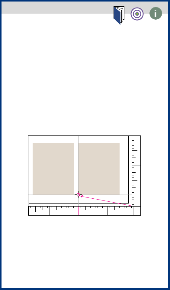
To change the ruler origin:
Move the pointer to the lower right
1
corner of the rulers where the rulers
intersect.
2
Drag the pointer to where you want
the new ruler origin. As you drag, a
cross hair in the window and in the rulers indicates the changing ruler origin.
3
Release the mouse button to set the
new 0,0 point in the rulers.
16
8
0
160 88
Page 22
About the work area
In Adobe Illustrator, the work area
occupies the entire space within the
Illustrator document window, and
includes more than just the printable
page containing your artwork. The work
area is made up of four sections:
• Imageable area
• Nonimageable area
• Artboard
• Scratch area
jump to art
Page 23
Imageable area
The imageable area is the area within
the dotted lines representing the
portion of the page on which the
selected printer can print an image.
Many printers cannot print to the
edge of the paper.
jump to art
Page 24

Nonimageable area
The nonimageable area is the area
between the dotted and solid lines
representing any nonprintable margin
of the page. This example shows the
nonimageable area of an 8.5" x 11" page
for a standard laser printer.
jump to art
Page 25
Artboard
The artboard is the area within the solid
lines representing the region that can
contain printable artwork. The artboard
equals the imageable area plus any nonimageable area. By default, the artboard
is the same size as the page, but it can
be enlarged, as in the example shown.
The U.S. default artboard is 8.5" x 11",
but can be set as large as 120" x 120".
jump to art
Page 26
Scratch area
The scratch area is the area between
the solid lines, and the border of the
document window represents a space
on which you can create, edit, and store
elements of artwork before moving
them onto the artboard. Objects placed
on the scratch area are visible on-screen,
but they do not print.
jump to art
Page 27
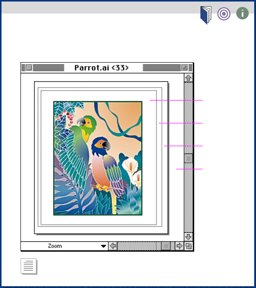
The work area
Click on any option for information on that option.
Imageable
area
Nonimageable
area
Artboard
Scratch area
return to text
Page 28
Changing the artboard size
The boundaries of the artboard define
the maximum printable area of your
document. By default, the artboard is
U.S. letter size (8.5 inches by 11 inches).
You can change the artboard’s dimensions using the Document Setup dialog
box.
To change the size of the artboard:
Choose File > Document Setup.
1
2 Choose any of the following options:
• Choose a preset size from the Size
pop-up menu.
• Choose Custom from the Size pop-up
menu, and enter the dimensions you
want in the Dimensions text boxes, up
to 120 inches by 120 inches. You can
change the units of the artboard size by
choosing a different ruler unit size from
the Ruler Units pop-up menu.
Page 29
• Select the Use Page Setup option to
set the size of the artboard to match the
page size set in the Page Setup dialog
box. The size of the artboard then
changes any time you choose a new
page size in the Page Setup dialog box.
3 Click OK.
jump to art
See also
• About the work area
• Setting up standard and custom
pages
• Document Setup dialog box
Page 30
Aligning the artboard with the
printed page
The artboard’s dimensions do not necessarily match the paper sizes used by
printers. As a result, when you print a
document, the program divides the artboard into one or more rectangles that
correspond to the page size available on
your printer. Dividing the artboard to fit
a printer’s available page size is called
tiling.
You define the page size by selecting a
page type in the Page Setup dialog box.
On most printers, the imageable area
is slightly smaller than the page. The
imageable area is surrounded by either
dotted lines or a gray rectangle. (This
area is usually centered on the artboard
by default; however, if an inkjet printer
is selected, the imageable area may
be displayed to the left and top of the
artboard.)
Note: The imageable area and page size
is not a limitation when printing to
imagesetters that handle large media.
Imagesetters can typically print to the
edge of the page. The page size used by
an imagesetter may be larger than
Page 31

the page size specified in Illustrator,
enabling you to print bleeds, for
example, that run past the edge of
the page.
As you work with tiled artwork, be sure
to consider how the artwork relates to
the boundaries of the page grid and to
the total dimensions of the artboard. For
example, if the artwork is tiled onto six
pages, part of the artwork will print on
a separate sheet of paper that corresponds to page 6. If you specify printing
only from pages 1 to 5, the part of the
artwork that is on page 6 won’t print.
The program may print blank pages if
the document is tiled so that the bounding box of the artwork intersects pages
that do not contain any artwork. The
bounding box is a transparent border
that defines the boundaries of your artwork. In the following illustration, the
bounding box surrounds the artwork,
not its direction lines.
See also
• About the work area
• Setting up standard and custom
pages
Page 32

Choosing tiling options
You set how pages tile using the options
in the Document Setup dialog box—
Single Full Page, Tile Full Pages, and Tile
Imageable Areas. These options let you
print the artwork on one or more pages,
printing each page according to the
page size defined in the Page Setup
dialog box.
To set whether the tiling format is
visible on-screen:
Choose View > Show Page Tiling or
View > Hide Tiling.
To change the page tiling options:
Choose File > Document Setup.
1
2 Choose one of the following options:
jump to art
• Select the Single Full Page option (the
default) to view and print one page.
Page 33

• Select the Tile Full Pages option to
view and print multiple pages containing
separate pieces of artwork. For example,
you can use this option to print a twopage brochure.
To view and print multiple pages, the
artboard size set in the must be large
enough to fit more than one full page at
a time.
Note: With the Tile Full Pages option,
any artwork that extends past the
imageable area of a given page is not
printed.
• Select the Tile Imageable Areas option
to view and print a single piece of
artwork that is too large to fit on one
page. For example, you could use this
option to print artwork for a large poster
onto several sheets of standard-size
paper for proofing.
When you print a document using this
option, the artwork is divided among
the imageable areas of the pages.
3 Click OK.
Page 34

If you have set up the document to view
and print multiple pages, the document
is tiled onto pages numbered from left
to right and from top to bottom, starting
with page 1. These page numbers
appear on-screen for your reference
only; they do not print. The numbers
enable you to print all of the pages in
the document or specify particular
pages to print.
The page or set of pages is aligned with
the center of the artboard by default.
However, you can reposition pages on
the artboard using the page tool, as
described next in moving the page
boundaries.
See also
• About the work area
• Setting up standard and custom
pages
• Document Setup dialog box
Page 35

Tiling options
Single Page option:
Letter size page
11” x 14” artboard
Tile Full Pages option: Letter size page
20”x 14” artboard
Page 36

Tile Imageable Areas
option: Letter size page
40”x 60” artboard
Page 37

Moving the page boundaries
You can adjust the placement of a page
on the artboard to control how artwork
is printed on the page. This is a good
way to avoid having the artwork extend
past the boundaries of the current page.
You can adjust the page on any of the
three View displays. You may find it easier to choose View > Fit In Window first
so that you can see more of the document while you adjust the pages.
Note: When you set up your page, you
can set the page size so that all of the
artwork fits on one page, as described in
Changing the artboard size.
Drag the page . . . to the new location.
Page 38

See also About the work area
To adjust a page using the page tool:
Select the page tool. The pointer is a
1
dotted cross in the active window.
2 Drag the page to the new location. As
you drag, two gray rectangles appear:
the outer rectangle indicates the page
size, and the inner rectangle indicates
the page’s printable area.
Note: To move a page past the artboard
boundary, change the artboard’s size in
the Document Setup dialog box. Any
part of a page that extends past the
artboard boundary is not displayed or
printed.
To adjust the artwork placement by
moving it:
Unlock any locked objects and
1
display any hidden objects. (See Locking
and hiding objects, Locking layers, and
Hiding and showing layers.)
2 Choose the selection tool.
3 Choose Edit > Select All.
4 Drag the artwork to the new position
within the page boundaries.
Page 39

Setting up standard and custom pages
Using the Document Setup dialog box (to set the artboard size and
page tiling) with the Page Setup dialog box (to set different page sizes
and orientations) lets you create standard- and custom-size pages.
Select the Use Page Setup option in the Document Setup dialog box to
override the dimensions set in the Document Setup dialog box. If you
have artwork with bleeds, making the artboard larger than the page
leaves room for crop marks, trim marks, and registration marks.
Vertical letter page
Document Setup:
•
Use Page Setup
Page Setup:
•
US letter paper
•
Portrait orientation
Page 40

Setting up standard and custom pages
Horizontal letter page
Document Setup:
• Use Page Setup
Page Setup:
• US letter paper
• Landscape orientation
return to text
Page 41

Setting up standard and custom pages, continued
Vertical tabloid page
Document Setup:
• Use Page Setup
Page Setup:
• Tabloid paper
• Portrait orientation
return to text
Page 42

Setting up standard and custom pages, continued
Horizontal tabloid page
Document Setup:
• Use Page Setup
Page Setup:
• Tabloid paper
• Landscape orientation
return to text
Page 43

Setting up standard and custom pages, continued
Two-page spread
return to text
Document Setup:
• Custom artboard
(19.5" by 13.5")
• Landscape orientation
• Tile Full Pages view
Page Setup:
• US letter paper
• Portrait orientation
Page 44

Setting up standard and custom pages, continued
Standard envelope – center fed
Document Setup:
• Use Page Setup
Page Setup:
• Envelope paper
• Landscape orientation
return to text
Page 45

Setting up standard and custom pages, continued
US letter page with bleed
Document Setup:
• Tabloid paper
• Portrait orientation
• Single Full Page view
Page Setup:
return to text
• US letter paper
• Portrait orientation
Page 46

Setting up standard and custom pages, continued
Custom page
Document setup:
• Custom artboard
(22.75" by 25.3375")
• Portrait orientation
• Tile Imageable Areas
Page Setup:
• US letter paper
• Landscape orientation
return to text
Page 47

Document Setup dialog box
Click on any option for information on that option.
return to text
Page 48

Moving and Aligning
Objects
Moving and copying objects
Cutting and pasting
Deleting objects
Rotating the x and y axes
Stacking objects
Moving objects to the front and back
of the artwork
Pasting objects in front of and in
back of other objects
Pasting objects in their current layer
Using the Control palette
Using the measure tool
Using guides
Grouping and ungrouping objects
Locking and hiding objects
Page 49

Moving and copying objects
You can move or copy objects in your
artwork by
•
Cutting and pasting
•
Dragging to move or copy
•
Dragging between applications
including open Illustrator and Photoshop documents
•
Using the arrow keys
•
Using the Move command
•
Using the Transform Each command
when Moving groups of objects
•
Using the Control palette.
In addition, you can use guides to align
objects with precision.
You can also use the Option key or the
Move dialog box to move copies of
objects rather than the objects themselves. In this case, if the object you are
copying is part of a group, the copy
becomes part of the same group.
Page 50

If the copy is made when you are moving groups of objects or objects on a
number of layers, the copied objects are
all included in the topmost group or
layer. To make a copy outside of the
object’s group, use the Copy and Paste
commands in the Edit menu.
See also
• Choosing preferences that affect
how objects move
• Aligning and distributing objects
vertically and horizontally
• Moving groups of objects
• Offsetting objects
• Moving objects to the front and
back of the artwork
• Pasting objects in front of and in
back of other objects
• Pasting objects in their current
layer
Page 51

Choosing preferences that affect how
objects move
The General Preferences dialog box lets
you specify how an object is moved.
To set preferences that affect how
objects move:
Choose File > Preferences > General.
1
2 Choose one or more of the following
options:
• Select the Snap to Point option to
specify whether, when you drag an
object, it “snaps” to an anchor point
or a guide when the pointer is within
2 pixels of the anchor point or guide.
This option is on by default. You can
turn this option off if you want to drag
objects without restricting their movement in this way.
• Enter an angle between 0 and 360
degrees in the Constrain Angle text box
to rotate the x and y axes. The rotation of
the axes determines how drawing and
movement are constrained when you
hold down the Shift key. See Rotating the
x and y axes for more information.
Page 52

• In the Cursor Key text box, enter the
distance you want each press of an
arrow key to move a selection.
• Select the Transform Pattern Tiles
option to transform a pattern when you
move or transform an object painted
with a pattern. For more information on
patterns, see Creating and working with
patterns.
3 Click OK.
Page 53

Cutting and pasting
Cutting and pasting lets you move or
copy objects in your artwork.
To move or copy an object by pasting:
Select the object you want to cut.
1
2 Choose Edit > Cut or Edit > Copy.
3 If you want to paste into another
document, open the document.
Note: To paste a bitmap PICT version of
the selected object onto the Clipboard
for pasting into other applications, hold
down the Option key while choosing the
Copy command.
4 Choose one of the following options:
• Choose Edit > Paste to paste the
objects into the center of the active
window.
• Choose Edit > Paste in Front to paste
the object directly in front of the
selected object.
Page 54

• Choose Edit > Paste in Back to paste
the object directly in back of the
selected object.
See also Pasting objects in front of and
in back of other objects.
Page 55

Dragging to move or copy
Dragging lets you move or copy objects
in your artwork.
To move an object or a copy of an
object by dragging:
Select the object. Then position the
1
pointer on an anchor point or path
segment of the selected object.
2 Drag the object to its new location.
Hold down the Shift key to constrain the
object to multiples of 45 degrees.
To drag a copy of the object, hold down
the Option key as you drag.
Press the Option key to copy the selection.
as you drag . . .
Page 56

Dragging between applications
You can use the drag and drop capability
to move or copy objects between
applications.
To move a copy of an object between
Illustrator documents or between
Illustrator and Photoshop documents
by dragging:
Open the document to which you
1
want to drag the object.
2 Select the object. Then position the
pointer on an anchor point or path
segment of the selected object.
3 Drag the object to its new location.
See also Using the drag and drop feature
to import and export artwork.
Page 57

Using the arrow keys
You can precisely move or copy objects
in your artwork using the arrow keys.
To move an object using the arrow
keys:
Select the object.
1
2 Press the arrow key that indicates the
direction in which you want the object
to move.
The distance the object moves each
time you press an arrow key is determined by the value specified in the
Cursor Key text box of the General
Preferences dialog box; the default
distance is 1 point (.0139 inch).
Page 58

Using the Move command
You can move or copy objects a specified amount using the Move command.
To move or copy an object a specific
distance and direction:
Select the object.
1
2 Choose Arrange > Move, or hold
down the Option key and click the
selection tool.
The Move dialog box displays the
results of the last move or measure
operation using the unit of measure
set in the General Preferences dialog
box. See defining ruler units for more
information.
3 Choose one of two options:
• Enter the horizontal and vertical
distances that you want the object to
move. Positive values move the object
up and to the right of the x axis; negative values move an object down and
to the left.
Page 59

• Enter the distance and angle for the
move. The angle you enter is calculated
in degrees from the x axis. Positive
angles specify a counterclockwise
move; negative angles specify a clockwise move. You can also enter values
between 180 and 360 degrees; these
values are converted to their corresponding negative values (for example,
a value of 270 degrees is converted to
–90 degrees).
90˚
135˚
45˚
180˚
-135˚ -45˚
-90˚
Directions relative to the x axis
0˚
Page 60

Aligning and distributing objects
vertically and horizontally
The Align palette enables you to align
selected objects along the axis you
specify. You can align objects along the
vertical axis, using the rightmost, center, or leftmost anchor point of the
selected objects. You can also align
objects along the horizontal axis using
the topmost, center, and bottommost
anchor points of the selected objects.
Note: Paragraph alignment of point
type over-rides the Align Objects
commands. For more information,
see Specifying alignment options.
Page 61

In addition, you can distribute objects
evenly along the horizontal axis or
vertical axis.
Alignment option: Alignment option:
Horizontal center Vertical center
To align or distribute objects:
Select the objects you want to align
1
or distribute.
2 Choose Window > Show Align.
3 Click the icon representing the type
of alignment or distribution you want.
Page 62

Moving groups of objects
The Move option in the Transform Each
dialog box moves objects in a selection
in a specified or random direction. You
can use the Random option to give a
slightly less rigid, more natural look to
a group of items. For example, if you
draw a brick wall, and want the bricks to
appear slightly offset from each other
instead of perfectly aligned, you could
select the Random option.
To use the Move Each option:
Select the objects you want to move.
1
2 Choose Arrange > Transform Each.
3 In the Move Horizontal and Vertical
text boxes, enter the distance you want
to move the selected objects, or use the
associated sliders. These numbers must
be between –4000 and 4000 points, and
must not cause the objects to move
beyond the edge of the artboard.
Page 63

4 Choose one of two options:
• To move the objects by the specified
amounts, click OK.
• To move the objects randomly, but no
more than the specified amounts, select
the Random option. Then click OK.
Page 64

Offsetting objects
You can create a replica of a path, set off
from the selected path by a specified
distance, using the Offset Path filter.
This is useful when you want to create
concentric shapes or make many replications of a path at a regular distance
from the original path. You can create an
offset path from a closed path or an
open path; if created from a closed path,
the new offset path appears the specified distance outside or inside the
original path.
Original Offset paths: –2 pts.
Page 65

To create an offset path:
Select the paths you want to offset.
1
2
Select Filter > Objects > Offset Path.
3
Specify the Offset distance, Line
join type, and Miter limit. For more
information about these options,
see Setting stroke attributes with
the Paint Style palette.
4
Click OK.
Page 66

Deleting objects
Deleting an object removes it
permanently.
To delete an object:
Select the object.
1
2 Press the Delete key or choose
Edit > Clear.
Page 67

Rotating the x and y axes
When you open a new document, the x
and y axes are parallel to the horizontal
and vertical sides of the window. You
can rotate the axes by specifying an
angle of constraint in the General Preferences dialog box.
Rotating the axes is useful if your artwork contains elements that are rotated
to the same angle, such as a logo and
text displayed on a 20-degree angle.
Instead of rotating each element you
add to the logo, you can simply rotate
the axes by 20 degrees. Everything
you draw will be created along the
new axes.
y
Normal
x
Page 68

y
y
y
x
20°
x
Constrain angle: 20°Constrain angle: 20°;
object rotated 20
20°
x
°
You can then use the Shift key to constrain the movement of one or more
objects so that they move in a precise
horizontal, vertical, or diagonal
direction (in 45-degree increments)
relative to the current orientation of
the x and y axes.
Pressing the Shift key while dragging or
drawing limits movement to 45
°
increments.
Page 69

The following objects and actions are
aligned along the new axes:
• Text objects, gradient angles you
draw with the gradient tool, and objects
you draw with the rectangle, oval, or
graph tool
• Scaling, reflecting, and shearing
• Moving objects with the arrow keys
• Any objects or operations to which
you apply constraint (by holding down
the Shift key while performing the
action) limiting them to 45-degree
multiples relative to the axes
• The angle reported in the Info palette
The following objects and actions are
not affected by the new axis:
• Objects that already exist
• Rotating and blending
• Drawing with the pencil or auto-
trace tool
Page 70

To rotate the axes:
Choose File > Preferences > General.
1
2 Enter the angle at which you want the
axes rotated in the Constrain Angle text
box. If you enter a positive number, the
axes are rotated counterclockwise. If
you enter a negative number, the axes
are rotated clockwise.
3 Click OK.
The rotation of the axes is saved in
Adobe Illustrator’s Preferences file; it
therefore affects new artwork in all
documents until you change its value.
Page 71

Stacking objects
The Adobe Illustrator program stacks
successively drawn objects, beginning
with the first object drawn. How objects
are stacked determines how they are
displayed when they overlap. In addition, stacking is important when work-
ing with masks.
You can change the stacking order, also
called the painting order, of objects in
your artwork at any time. You can also
control how overlapping objects are
displayed by using layers.
Note: Grouping objects may affect the
way the objects are stacked in relation
to other, nongrouped objects in the
artwork. See Grouping and ungrouping
objects for more information.
Page 72

Moving objects to the front and back
of the artwork
The Bring to Front and Send to Back
commands let you move an object to
the front or back of the stack of objects
on its layer. (For more information, see
about layers.)
If the object is part of any type of
group—including masked artwork,
compound paths, text, and word
wraps—the object is moved to the front
or back of the group, rather than the
front or back of the entire layer.
Selected object Object in middle
of stack
Page 73

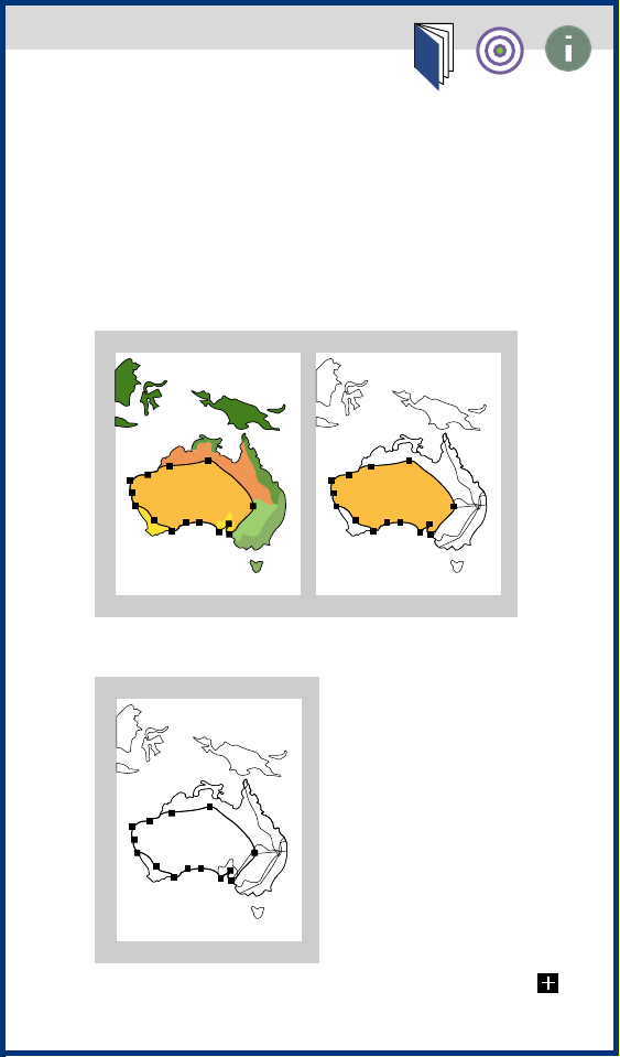
Object brought Object repositioned
to front in stack
To make an object the frontmost or
backmost object on its group or layer:
Select the object you want to move.
1
2 Choose Arrange > Bring to Front or
Arrange > Send to Back.
Page 74

Pasting objects in front of and in back
of other objects
The Paste in Front and Paste in Back
commands let you paste copies of
objects directly on top of and behind the
objects you select. This is useful if you
want to then move the copy a specified
distance from the original’s location.
These commands also enable you to
paste the artwork into the same position
in a new document as it was in the old,
relative to the page origin.
To move an object in front of or in back
of other objects in the stacking order:
Select the object you want to move.
1
2 Choose Edit > Cut. The selected
object is temporarily deleted and is
placed onto the Clipboard.
3 Select the object or objects in front of
or in back of which you want the cut
object to appear.
4 Choose Edit > Paste In Front or Edit >
Paste In Back.
Page 75

The cut object is pasted into position.
If no object was selected in step 3, the
object is pasted on top of or in back of
the stack.
Red object selected Red object cut
Yellow object Red object pasted
selected in back
Page 76

If you paste more than one object, all
pasted objects appear in front of or in
back of the selected artwork. However,
the relative painting order among the
individual pasted objects remains the
same. If you are working with multiple
layers in your document that you have
defined with the Layers palette, the layers may affect how objects are pasted.
See Moving objects between layers for
more information.
Page 77

Pasting objects in their current layer
Pasted objects (even if copied from different layers) are placed directly in front
of or in back of all selected objects on
the current layer if the Paste Remembers
Layers option is turned off in the General Preferences dialog box. However,
the relative painting order among the
individual pasted objects remains the
same.
The Paste Remembers Layers option
makes objects you paste retain their
layering order. (See Moving objects
between layers for more information.)
To paste objects into their current
layer:
Choose File > Preferences > General.
1
2 Select the Paste Remembers Layers
option, and click OK.
Page 78

Using the Control palette
The Control palette displays information about selected objects. In addition,
you can use the palette to move, scale,
rotate, and resize objects.
To use the Control palette:
Choose Window > Show Control
1
Palette.
2 Select the object.
3 Choose any of the following options:
• To select the reference point from
which you are modifying the object,
click a handle on the square representing the object’s bounding box on
the palette.
• To move an object horizontally, enter
a value in the X text box.
• To move an object vertically, enter a
value in the Y text box.
• To change the width of an object,
enter a value in the W text box.
• To change the height of an object,
enter a value in the H text box.
Page 79

• To rotate an object, enter a new angle
between 0 and 360 degrees in the Angle
text box.
• To scale an object, enter a value in the
Scale text box.
4 Press the Tab key or Return key to
apply the change.
jump to art
Page 80

The Control palette
Click on any option for information on that option.
Point of origin for
transformation
Horizontal
position
Vertical position
return to text
Width Scale
Height Angle
Page 81

Using the measure tool
The measure tool calculates the distance between any two points in the
work area. When you measure from one
point to another, the distance measured
is displayed in the Info palette. The Info
palette shows the horizontal and vertical distance traveled from the x and y
axes, the absolute horizontal and vertical distance, the total distance, and the
angle measured.
All measurements except the angle are
calculated by defining ruler units in the
General Preferences dialog box or in the
Document Setup dialog box.
jump to art
Page 82

To measure the distance between two
points:
1 Select the measure tool.
2 Choose one of two options:
• Click the two points between which
you want to measure.
• Click the first point and drag to the
second point. Hold down the Shift key
to constrain the tool to multiples of
45 degrees.
If it was not previously displayed, the
Info palette appears.
Page 83

The Info palette
Horizontal
position
Absolute
horizontal
distance
measured
Angle
measured
Vertical
distance
from y axis
return to text
Absolute
vertical
distance
measured
Angle diagonal
distance measured
Page 84

Using guides
To help align text and graphic objects
on the page, you can create and display
dotted outlines, called guides, in the
background of the work area.
You can create two kinds of guides:
• Ruler guides are straight horizontal or
vertical lines created with the ruler.
These guides are the simplest to make
and are useful for setting alignment
lines across the length or width of the
work area.
• Guide objects are objects (such as
lines, rectangles, or any other artwork
consisting of paths, except type) that
have been converted to guides. Using
guide objects can help you plan and
create your artwork around one or more
objects. You can convert guide objects
back into graphic objects at any point.
New guides are locked in place to orient
your artwork. However, you can unlock
a guide to select, move, delete, modify,
or revert it to a graphic object.
Page 85

By default, objects are aligned with
guides whenever they are dragged
within 2 pixels of the guide. For information on how to turn this feature on
and off, see Choosing preferences that
affect how objects move.
Tip: To make working with multiple
guides easier, place all guides on a
single layer. You can then choose the
layer to select all guides for moving
or adjusting. See Creating layers
and setting layer options for more
information.
To create a ruler guide:
If the rulers are not already displayed,
1
choose View > Show Rulers.
2 Position the pointer on the right ruler
for a vertical guide, or on the bottom
ruler for a horizontal guide. Hold down
the Option key to switch the ruler guide
from horizontal to vertical and vice
versa.
Page 86

3 Hold down the mouse button and
drag the dotted ruler guide into position.
To convert an object into a guide
object:
Select an object, a group of objects,
1
or any combination of objects and
groups.
Page 87

2 Choose Object > Guides > Make.
Objects selected and converted to guides
with aligned artwork.
To move, delete, or release a guide:
Choose Object > Guides > Lock to
1
unlock the guide. When a guide is
locked, a check mark appears in front
of the Lock Guide command.
2 Select the guide you want to move,
delete, or release, and choose one of
three options:
• Move the guide by dragging or
copying.
• Delete the guide by pressing the
Delete key or choosing Edit > Cut.
Page 88

• Release the guide object, turning it
back into a regular graphic object, by
choosing Object > Guides > Release.
Note: The Lock Guides option locks all
guides in the document. To lock an individual guide, select the guide when the
Lock Guides option is turned off, and
>
choose Arrange
To delete all guides in the artwork:
Lock.
Choose Object > Guides > Delete All.
Page 89

Grouping and ungrouping objects
You can combine several objects into a
group so that the objects are treated as
a single unit. You can then move or
transform a number of objects without
affecting their individual positions or
attributes. For example, you might
group the objects in a logo design, so
that you can move and scale the logo as
one unit.
Groups can also be nested—that is, they
can be grouped within other objects or
groups to form larger groups.
To group or ungroup objects:
Select the objects to be grouped or
1
ungrouped. Selecting part of an object
and grouping it will group the entire
object.
2 Choose Arrange > Group or Arrange >
Ungroup.
See also
• Selecting grouped objects
• Grouping stacked objects
Page 90

Selecting grouped objects
Once objects have been grouped, selecting any part of the group with the selection tool selects the entire group. If you
are unsure whether an object is part of
a group, select it with this tool.
The direct-selection tool lets you select
a single path or object that is part of one
or several groups. If you have groups of
objects within other groups, you can
select the next group in the grouping
hierarchy using the group-selection
tool. Each successive click adds another
subset of grouped objects to the
selection.
AB C
Three groups: group A is part of group B,
which in turn is part of group C.
Page 91
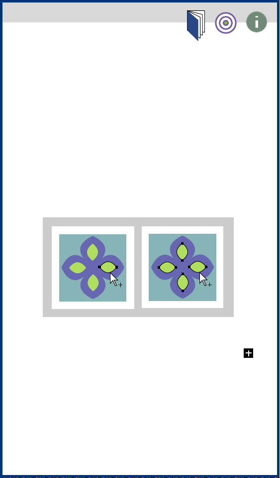
To select grouped objects with the
group-selection tool:
Select the group-selection tool.
1
2 Position the pointer on the path you
want to select, and click the mouse
button.
3 Click the same place again to select
successive groups until you have
selected everything you want to include
in your selection.
First click selects Second click selects
an object. group A.
Page 92

Third click selects Fourth click selects
next group next group
(group B). (group C).
Page 93

Grouping stacked objects
Grouped objects must be stacked in succession on the same layer of the artwork; therefore, grouping may change
both the layering of objects and their
stacking order on a given layer. See
Stacking objects and About layers for
more information.
Grouped objects are stacked together
behind the frontmost object in the
group. If you group two objects that are
separated by a nongrouped object in the
stacking order, the non- grouped object
will be moved behind the grouped
objects.
Three objects: Front and back
front and back objects grouped
objects selected
Page 94

Locking and hiding objects
You can use the Lock and Hide commands to isolate parts of your artwork
on which you do not want to work. Once
an object has been locked or hidden, it
cannot be selected or modified in any
way. These features are useful when you
are working on objects that overlap. In
addition, the Hide command makes
objects temporarily invisible, and so
may speed performance when you work
on large or complex artwork.
Locked objects remain locked when files
are closed and reopened. However, hidden objects reappear when files are
reopened.
You can lock or hide entire objects only.
Hiding the anchor points and edges of a
selected object and locking or hiding
them affects the entire object. However,
you can lock or hide individual objects
within groups as well as lock or hide
entire groups.
Page 95

To lock or hide artwork:
Choose one of the following options:
• To lock objects, first select the objects,
and then choose Arrange > Lock.
• To lock all unselected objects, hold
down the Option key and choose
Arrange > Lock.
• To hide a selected object, select the
objects, and choose Arrange > Hide.
• To hide all unselected objects, hold
down the Option key and choose
Arrange > Hide.
To unlock or show all objects:
Choose Arrange > Unlock All or Arrange
> Show All. All previously locked objects
are unlocked and selected. Any previously selected objects are deselected.
To unlock or show all objects within a
selected group:
Select an unlocked and visible
1
element within a group.
2 Hold down the Option key and
choose Arrange > Unlock All or
Arrange > Show All.
Page 96

A
B
C
D
E
F
G
H
K
L
M
N
O
P
Q
R
S
T
U
A
Actual Size command 10
adding values in fields 19
Align Objects command 60
aligning objects 60
angle of constraint 67
arrow keys, moving objects with 57
I
J
artboard 25
Artwork command 5
Artwork view 4
Artwork View Speedup filter 5
B
bounding box
defined 31
Bring to Front command 72
C
Clear command 66
Constrain Angle option 51, 70
Control palette 78–79
copying
objects 49–59
Cursor Key option 57
custom views 13–14
Cut command 74
V
W
X
Y
Z
D
Delete key, for removing objects 66
deleting objects 66
displaying documents 4–6
Page 97

A
D
G
B
C
distributing objects 60
Document Setup command 28, 32–33, 39
E
F
F
fields, adding and subtracing values in 19
Fit In Window command 12
H
K
L
M
N
O
P
Q
R
S
T
U
V
W
X
G
I
J
General Preferences dialog box
Constrain Angle option 51, 70
Cursor Key 52
Paste Remembers Layers 77
Ruler Units 18
Snap to Point option 51
Transform Pattern Tiles 52
grouped objects
moving 72
selecting 90
grouping
objects 89
stacked objects 93
guide objects 84–88
H
hand tool 9
hiding and locking objects 94–95
I
imageable area 23
imagesetters 30
Info palette 81
Y
Z
Page 98

A
B
C
D
E
F
G
H
K
L
M
N
O
P
Q
R
S
T
U
V
W
X
L
Lock command 95
locking objects 94
M
magnifying and reducing views 10–12
Make Guide option 87
I
J
measure tool 81
Move command 58
Move option (Transform Each dialog box) 62
moving groups of objects 62
moving objects 37, 49, 49–59
by dragging 55
using arrow keys 57
moving the view of a document 9
N
New Window command 15
nonimageable area 24
O
Offset Path filter 64
P
page boundaries 37
Page Setup dialog box 39
page tool 38
painting order. See stacking order
Paste command 53
Paste in Back command 54, 74
Paste in Front command 53, 74
Y
Z
Page 99

A
B
C
D
E
F
G
H
K
L
M
N
O
P
Q
R
S
T
U
V
W
X
Paste Remembers Layers option 77
picas 17
PICT 53
placing
images 7
points 17
Preview and Print Patterns option 7
I
J
Preview command 5
Preview Selection command 6
Preview Selection view 4
Preview view 4
printing
tiling 32
R
Random option 62
rotating the x and y axes 67
ruler guides 84
ruler origin 20
rulers 16–21
changing units 17, 28
S
scratch area 26
selecting
grouped objects 90
Send to Back command 72
Show Control Palette option 78
Single Full Page option 20, 32
Snap to Point option 51
Y
Z
Page 100

A
B
C
D
E
F
G
H
K
L
M
N
O
P
Q
R
S
T
U
V
W
X
stacking order 71
subtracting values in fields 19
T
Tile Full Pages option 20, 33
Tile Imageable Areas option 33
tiling 30, 32
I
J
Transform Each command 62
Transform Pattern Tiles option 52
U
ungrouping objects 89
unit of measure 17
unit values, converting 19
units arithmetic, using 19
Unlock All command 95
Use Page Setup option 29
V
viewing
actual size 12
Artwork 5
custom 13
entire document 12
magnified 10
multiple windows 15
patterns 7
placed images 7
Preview 5
Preview Selection 6
reduced 10
Y
Z
 Loading...