

Page 1

Using Fireworks
Page 2

Trademarks
Afterburner, AppletAce, Attain, Attain Enterprise Learning System, Attain Essentials, Attain Objects for Dreamweaver,
Authorware, Authorware Attain, Authorware Interactive Studio, Authorware Star, Authorware Synergy, Backstage, Backstage
Designer, Backstage Desktop Studio, Backstage Enterprise Studio, Backstage Internet Studio, Contribute, Design in Motion,
Director, Director Multimedia Studio, Doc Around the Clock, Dreamweaver, Dreamweaver Attain, Drumbeat, Drumbeat 2000,
Extreme 3D, Fireworks, Flash, Fontographer, FreeHand, FreeHand Graphics Studio, Generator, Generator Developer's Studio,
Generator Dynamic Graphics Server, Knowledge Objects, Knowledge Stream, Knowledge Track, LikeMinds, Lingo, Live Effects,
MacRecorder Logo and Design, Macromedia, Macromedia Contribute, Macromedia Coursebuilder for Dreamweaver,
Macromedia M Logo & Design, Macromedia Flash, Macromedia Xres, Macromind, Macromind Action, MAGIC, Mediamaker,
Multimedia is the Message, Object Authoring, Power Applets, Priority Access, Roundtrip HTML, Scriptlets, SoundEdit,
ShockRave, Shockmachine, Shockwave, shockwave.com, Shockwave Remote, Shockwave Internet Studio, Showcase, Tools to
Power Your Ideas, Universal Media, Virtuoso, Web Design 101, Whirlwind and Xtra are trademarks of Macromedia, Inc. and
may be registered in the United States or in other jurisdictions including internationally. Other product names, logos, designs,
titles, words or phrases mentioned within this publication may be trademarks, servicemarks, or tradenames of Macromedia, Inc.
or other entities and may be registered in certain jurisdictions including internationally.
This guide contains links to third-party Web sites that are not under the control of Macromedia, and Macromedia is not
responsible for the content on any linked site. If you access a third-party Web site mentioned in this guide, then you do so at your
own risk. Macromedia provides these links only as a convenience, and the inclusion of the link does not imply that Macromedia
endorses or accepts any responsibility for the content on those third-party sites.
Apple Disclaimer
APPLE COMPUTER, INC. MAKES NO WARRANTIES, EITHER EXPRESS OR IMPLIED, REGARDING THE
ENCLOSED COMPUTER SOFTWARE PACKAGE, ITS MERCHANTABILITY OR ITS FITNESS FOR ANY
PARTICULAR PURPOSE. THE EXCLUSION OF IMPLIED WARRANTIES IS NOT PERMITTED BY SOME STATES.
THE ABOVE EXCLUSION MAY NOT APPLY TO YOU. THIS WARRANTY PROVIDES YOU WITH SPECIFIC
LEGAL RIGHTS. THERE MAY BE OTHER RIGHTS THAT YOU MAY HAVE WHICH VARY FROM STATE TO
STATE.
Copyright © 2003 Macromedia, Inc. All rights reserved. This manual may not be copied, photocopied, reproduced,
translated, or converted to any electronic or machine-readable form in whole or in part without prior written approval of
Macromedia, Inc. Part Number ZFW70M200
Acknowledgments
Project Management: Gary White
Writing: Dale Crawford, Tonya Estes, Naheeda Ravjani
Editing Management: Rosana Francescato
Editors: Linda Adler, Mary Kraemer, Noreen Maher
Production Management: Patrice O’Neill
Multimedia Development: Aaron Begley
Photography: Chris Basmajian
Production: Adam Barnett, John Francis, Jeff Harmon
Special thanks to Jeff Ahlquist, Doug Benson, Rob McCullough, Joe Merritt, Melana Orton
First Edition: September 2003
Macromedia, Inc.
600 Townsend St.
San Francisco, CA 94103
Page 3

CONTENTS
CHAPTER 1: Selecting and Transforming Objects . . . . . . . . . . . . . . . . . . . . . . . . . 7
Selecting objects . . . . . . . . . . . . . . . . . . . . . . . . . . . . . . . . . . . . . . . . . . . . . . . . . . . 7
Selecting pixels . . . . . . . . . . . . . . . . . . . . . . . . . . . . . . . . . . . . . . . . . . . . . . . . . . . 10
Editing selected objects . . . . . . . . . . . . . . . . . . . . . . . . . . . . . . . . . . . . . . . . . . . . . 19
Transforming and distorting selected objects and selections . . . . . . . . . . . . . . . . . 21
Organizing objects. . . . . . . . . . . . . . . . . . . . . . . . . . . . . . . . . . . . . . . . . . . . . . . . . 24
CHAPTER 2: Working with Bitmaps . . . . . . . . . . . . . . . . . . . . . . . . . . . . . . . . . . . 29
Working with bitmaps. . . . . . . . . . . . . . . . . . . . . . . . . . . . . . . . . . . . . . . . . . . . . . 29
Creating bitmap objects. . . . . . . . . . . . . . . . . . . . . . . . . . . . . . . . . . . . . . . . . . . . . 30
Drawing, painting, and editing bitmap objects . . . . . . . . . . . . . . . . . . . . . . . . . . . 31
Retouching bitmaps . . . . . . . . . . . . . . . . . . . . . . . . . . . . . . . . . . . . . . . . . . . . . . . 34
Adjusting bitmap color and tone . . . . . . . . . . . . . . . . . . . . . . . . . . . . . . . . . . . . . . 39
Blurring and sharpening bitmaps. . . . . . . . . . . . . . . . . . . . . . . . . . . . . . . . . . . . . . 49
Adding noise to an image . . . . . . . . . . . . . . . . . . . . . . . . . . . . . . . . . . . . . . . . . . . 53
CHAPTER 3: Working with Vector Objects . . . . . . . . . . . . . . . . . . . . . . . . . . . . . 55
Drawing vector objects . . . . . . . . . . . . . . . . . . . . . . . . . . . . . . . . . . . . . . . . . . . . . 55
Editing paths. . . . . . . . . . . . . . . . . . . . . . . . . . . . . . . . . . . . . . . . . . . . . . . . . . . . . 71
CHAPTER 4: Using Text . . . . . . . . . . . . . . . . . . . . . . . . . . . . . . . . . . . . . . . . . . . . 79
Entering text . . . . . . . . . . . . . . . . . . . . . . . . . . . . . . . . . . . . . . . . . . . . . . . . . . . . 79
Editing text . . . . . . . . . . . . . . . . . . . . . . . . . . . . . . . . . . . . . . . . . . . . . . . . . . . . . . 81
Applying strokes, fills, and effects to text . . . . . . . . . . . . . . . . . . . . . . . . . . . . . . . . 89
Attaching text to a path . . . . . . . . . . . . . . . . . . . . . . . . . . . . . . . . . . . . . . . . . . . . . 90
Transforming text . . . . . . . . . . . . . . . . . . . . . . . . . . . . . . . . . . . . . . . . . . . . . . . . . 92
Converting text to paths . . . . . . . . . . . . . . . . . . . . . . . . . . . . . . . . . . . . . . . . . . . . 92
Importing text. . . . . . . . . . . . . . . . . . . . . . . . . . . . . . . . . . . . . . . . . . . . . . . . . . . . 93
Checking spelling . . . . . . . . . . . . . . . . . . . . . . . . . . . . . . . . . . . . . . . . . . . . . . . . . 94
Using the Text Editor . . . . . . . . . . . . . . . . . . . . . . . . . . . . . . . . . . . . . . . . . . . . . . 95
3
Page 4

CHAPTER 5: Applying Color, Strokes, and Fills . . . . . . . . . . . . . . . . . . . . . . . . . . 97
Using the Colors section of the Tools panel . . . . . . . . . . . . . . . . . . . . . . . . . . . . . . 98
Organizing swatch groups and color models . . . . . . . . . . . . . . . . . . . . . . . . . . . . . 98
Using color boxes and color pop-up windows . . . . . . . . . . . . . . . . . . . . . . . . . . . 105
Working with strokes. . . . . . . . . . . . . . . . . . . . . . . . . . . . . . . . . . . . . . . . . . . . . . 106
Working with fills . . . . . . . . . . . . . . . . . . . . . . . . . . . . . . . . . . . . . . . . . . . . . . . . 110
Applying gradient and pattern fills . . . . . . . . . . . . . . . . . . . . . . . . . . . . . . . . . . . 111
Adding texture to strokes and fills . . . . . . . . . . . . . . . . . . . . . . . . . . . . . . . . . . . . 116
CHAPTER 6: Using Live Effects . . . . . . . . . . . . . . . . . . . . . . . . . . . . . . . . . . . . . 119
Applying Live Effects. . . . . . . . . . . . . . . . . . . . . . . . . . . . . . . . . . . . . . . . . . . . . . 120
Editing Live Effects . . . . . . . . . . . . . . . . . . . . . . . . . . . . . . . . . . . . . . . . . . . . . . . 124
CHAPTER 7: Layers, Masking, and Blending . . . . . . . . . . . . . . . . . . . . . . . . . . . 129
Working with layers. . . . . . . . . . . . . . . . . . . . . . . . . . . . . . . . . . . . . . . . . . . . . . . 129
Masking images. . . . . . . . . . . . . . . . . . . . . . . . . . . . . . . . . . . . . . . . . . . . . . . . . . 134
Blending and transparency . . . . . . . . . . . . . . . . . . . . . . . . . . . . . . . . . . . . . . . . . 152
CHAPTER 8: Using Styles, Symbols, and URLs. . . . . . . . . . . . . . . . . . . . . . . . . 155
Using styles . . . . . . . . . . . . . . . . . . . . . . . . . . . . . . . . . . . . . . . . . . . . . . . . . . . . 155
Using symbols . . . . . . . . . . . . . . . . . . . . . . . . . . . . . . . . . . . . . . . . . . . . . . . . . . . 158
Working with URLs . . . . . . . . . . . . . . . . . . . . . . . . . . . . . . . . . . . . . . . . . . . . . . 164
CHAPTER 9: Slices, Rollovers, and Hotspots. . . . . . . . . . . . . . . . . . . . . . . . . . . 167
Creating and editing slices . . . . . . . . . . . . . . . . . . . . . . . . . . . . . . . . . . . . . . . . . . 167
Making slices interactive . . . . . . . . . . . . . . . . . . . . . . . . . . . . . . . . . . . . . . . . . . . 173
Preparing slices for export . . . . . . . . . . . . . . . . . . . . . . . . . . . . . . . . . . . . . . . . . . 180
Working with hotspots and image maps . . . . . . . . . . . . . . . . . . . . . . . . . . . . . . 185
CHAPTER 10: Creating Buttons and Pop-up Menus . . . . . . . . . . . . . . . . . . . . . 191
Creating button symbols . . . . . . . . . . . . . . . . . . . . . . . . . . . . . . . . . . . . . . . . . . . 191
Creating navigation bars . . . . . . . . . . . . . . . . . . . . . . . . . . . . . . . . . . . . . . . . . . . 200
Creating pop-up menus . . . . . . . . . . . . . . . . . . . . . . . . . . . . . . . . . . . . . . . . . . . 200
CHAPTER 11: Creating Animation . . . . . . . . . . . . . . . . . . . . . . . . . . . . . . . . . . . . 211
Building animation . . . . . . . . . . . . . . . . . . . . . . . . . . . . . . . . . . . . . . . . . . . . . . . 211
Working with animation symbols . . . . . . . . . . . . . . . . . . . . . . . . . . . . . . . . . . . . 212
Working with frames . . . . . . . . . . . . . . . . . . . . . . . . . . . . . . . . . . . . . . . . . . . . . 216
Tweening. . . . . . . . . . . . . . . . . . . . . . . . . . . . . . . . . . . . . . . . . . . . . . . . . . . . . . . 220
Previewing an animation . . . . . . . . . . . . . . . . . . . . . . . . . . . . . . . . . . . . . . . . . . . 221
Exporting your animation . . . . . . . . . . . . . . . . . . . . . . . . . . . . . . . . . . . . . . . . . . 221
Working with existing animations . . . . . . . . . . . . . . . . . . . . . . . . . . . . . . . . . . . . 223
Using multiple files as one animation . . . . . . . . . . . . . . . . . . . . . . . . . . . . . . . . . 224
4 Contents
Page 5

CHAPTER 12: Optimizing and Exporting . . . . . . . . . . . . . . . . . . . . . . . . . . . . . . 225
About optimizing . . . . . . . . . . . . . . . . . . . . . . . . . . . . . . . . . . . . . . . . . . . . . . . . 226
Using the Export Wizard. . . . . . . . . . . . . . . . . . . . . . . . . . . . . . . . . . . . . . . . . . . 226
Optimizing in the workspace. . . . . . . . . . . . . . . . . . . . . . . . . . . . . . . . . . . . . . . . 231
Exporting from Fireworks . . . . . . . . . . . . . . . . . . . . . . . . . . . . . . . . . . . . . . . . . . 247
Sending a Fireworks document as an e-mail attachment . . . . . . . . . . . . . . . . . . . 262
Using the File Management button. . . . . . . . . . . . . . . . . . . . . . . . . . . . . . . . . . . 262
CHAPTER 13: Automating Repetitive Tasks . . . . . . . . . . . . . . . . . . . . . . . . . . . . 263
Finding and replacing . . . . . . . . . . . . . . . . . . . . . . . . . . . . . . . . . . . . . . . . . . . . . 264
Batch processing . . . . . . . . . . . . . . . . . . . . . . . . . . . . . . . . . . . . . . . . . . . . . . . . . 267
Extending Fireworks . . . . . . . . . . . . . . . . . . . . . . . . . . . . . . . . . . . . . . . . . . . . . . 275
CHAPTER 14: Preferences and Keyboard Shortcuts . . . . . . . . . . . . . . . . . . . . . 281
Setting preferences. . . . . . . . . . . . . . . . . . . . . . . . . . . . . . . . . . . . . . . . . . . . . . . . 281
Changing keyboard shortcut sets . . . . . . . . . . . . . . . . . . . . . . . . . . . . . . . . . . . . 284
Working with configuration files . . . . . . . . . . . . . . . . . . . . . . . . . . . . . . . . . . . . . 286
About reinstalling Fireworks . . . . . . . . . . . . . . . . . . . . . . . . . . . . . . . . . . . . . . . . 287
Viewing package contents (Macintosh only) . . . . . . . . . . . . . . . . . . . . . . . . . . . . 287
INDEX . . . . . . . . . . . . . . . . . . . . . . . . . . . . . . . . . . . . . . . . . . . . . . . . . . . . . . . . . . 289
Contents 5
Page 6

6 Contents
Page 7

CHAPTER 1
Selecting and Transforming Objects
As you work in Macromedia Fireworks MX 2004, you manipulate vector and bitmap objects, text
blocks, slices and hotspots, and areas of pixels. Using the selection and transformation tools, you
can move, copy, delete, rotate, scale, or skew objects. In documents that have multiple objects,
you can organize the objects by stacking, grouping, and aligning them.
Selecting objects
Before you can do anything with any object on the canvas, you must select it. This applies to a
vector object, path, or points; a text block, word, or letter; a slice or hotspot; an instance; or a
bitmap object.
You can use any of the following to select objects:
The Layers panel displays each object. You can click an object in the Layers panel to it select
when the panel is open and layers are expanded. For more information, see Chapter 7, “Layers,
Masking, and Blending,” on page 129.
The Pointer tool selects objects when you click the objects or drag a selection area around
them.
The Subselection tool selects an individual object in a group or the points of a vector object.
The Select Behind tool selects an object that is behind another object.
The Export Area tool selects an area to be exported as a separate file.
For information about selecting specific areas of pixels in a bitmap image, see “Selecting pixels”
on page 10.
7
Page 8
Using the Pointer tool
The Pointer tool selects objects when you click them or when you drag a selection area around all
or part of the objects.
To select an object by clicking, do one of the following:
• Move the Pointer tool over the object’s path or bounding box and click.
• Click the object’s stroke or fill.
• Select the object in the Layers panel.
Tip: To preview what you would select if you were to click on an object beneath the pointer on the
canvas, choose the Mouse Highlight option in the Editing tab of the Preferences dialog box. For
more about preferences, see “Setting preferences” on page 281.
To select objects by dragging:
• Drag the Pointer tool to include one or more objects in the selection area.
Using the Subselection tool
You use the Subselection tool to select, move, or modify points on a vector path or an object that
is part of a group.
To move or modify objects with the Subselection tool:
1 Choose the Subselection tool.
2 Make a selection.
Selection handles appear.
3 Do one of the following:
■ To modify an object, drag one of its points or selection handles.
■ To move the entire object, drag anywhere in the object except a point or selection handle.
8 Chapter 1: Selecting and Transforming Objects
Page 9
Using the Select Behind tool
When working with graphics that contain multiple objects, you can use the Select Behind tool to
select an object that is hidden or obscured by other objects.
To select an object that is behind other objects:
• Click the Select Behind tool repeatedly over the stacked objects, progressing through the
objects top to bottom in stacking order until you select the object you want.
Note: You also can select a hard-to-reach object by clicking it in the Layers panel when the layers
are expanded.
Selection information in the Property inspector
Whenever you select an object, the Property inspector identifies the selection. The upper left area
of the Property inspector contains the following information about the selection:
• A description of the item being inspected
• A text box to enter a name for that item
Note: The name appears in the title bar of the document whenever you select this item. For slices
and buttons, the name is the filename when exported.
• The number of objects when more than one object is selected
Note: If the status bar is turned on (Windows only), selected objects are also identified in the status
bar at the bottom of the document window.
The Property inspector also displays information and settings for the object type selected. For
example, when you select a vector path, the Property inspector displays vector path properties,
such as stroke width and color.
Modifying a selection
After you select a single object, you can add objects to the selection and deselect objects that are
selected. Using a single command, you can select or deselect everything on every layer in a
document. You can also hide the selection path so that you can edit a selected object while
viewing it as it will appear on the web or in print.
To add to a selection:
• Hold down Shift while clicking additional objects with the Pointer, Subselection, or Select
Behind tool.
To deselect an object while leaving other objects selected:
• Hold down Shift while clicking the selected object.
Selecting objects 9
Page 10

To select everything on every layer in the document:
• Choose Select > Select All.
Note: Select All does not select hidden objects.
To deselect all selected objects:
• Choose Select > Deselect.
Note: You must deselect the Single Layer Editing preference to select all visible objects on all
layers in a document. When you choose the Single Layer Editing preference, only objects on the
current layer are selected. For more information, see “Organizing layers” on page 131.
To hide the path selection feedback of a selected object:
• Choose View > Hide Edges.
Note: You can use the Layers panel or the Property inspector to identify the selected object when
the outline and points are hidden.
To hide selected objects:
• Choose View > Hide Selection.
Note: Hidden objects are not exported. (This does not apply to slice and hotspot web objects on
the Web Layer.)
To show all objects:
• Choose View > Show All.
Note: To hide objects whether they are selected or not, you can click or drag along the Eye column
in the Layers panel.
Selecting pixels
You can edit pixels over an entire canvas or choose one of the selection tools to constrain your
editing to a particular area of an image:
The Marquee tool selects a rectangular area of pixels in an image.
The Oval Marquee tool selects an elliptical area of pixels in an image.
The Lasso tool selects a freeform area of pixels in an image.
The Polygon Lasso tool selects a straight-edged freeform area of pixels in an image.
The Magic Wand tool selects an area of similarly colored pixels in an image.
The pixel selection tools draw selection marquees that define the area of selected pixels. After you
draw the selection marquee, you can manipulate it by moving it, adding to it, or basing another
selection on it. You can edit the pixels inside the selection, apply filters to the pixels, or erase pixels
without affecting the pixels beyond the selection. You can also create a floating selection of pixels
that you can edit, move, cut, or copy.
10 Chapter 1: Selecting and Transforming Objects
Page 11

Bitmap selection tool options
When you choose the Marquee, Oval Marquee, Lasso, Polygon Lasso, or Magic Wand tool, the
Property inspector displays three Edge options for the tool:
Hard creates a marquee selection with a defined edge.
Anti-alias prevents jagged edges in the marquee selection.
Feather lets you soften the edge of the pixel selection.
You must set the Feather option before creating a feathered selection using a selection tool. You
can feather existing selections using the Feather command in the Select menu. For more
information, see “Feathering a pixel selection” on page 16.
When you choose the Marquee or Oval Marquee, the Property inspector also displays three
style options:
Normal lets you create a marquee in which the height and width are independent of each other.
Fixed Ratio constrains the height and width to defined ratios.
Fixed Size sets the height and width to a defined dimension.
Note: The Magic Wand tool also has a Tolerance setting. For more information, see “Selecting areas
of similar color” on page 12.
Creating pixel selection marquees
The Marquee, Oval Marquee, and Lasso tools in the Bitmap section of the Tools panel allow you
to select specific pixel areas of a bitmap image by drawing a marquee around them.
To select a rectangular or elliptical area of pixels:
1 Choose the Marquee or Oval Marquee tool.
2 Set the Style and Edge options in the Property inspector. For more information, see “Bitmap
selection tool options” on page 11.
3 Drag to draw a selection marquee, which defines the pixel selection.
Hold down Shift as you drag the Marquee or Oval Marquee tool to draw square or circular
marquees. To draw a marquee from a center point, deselect any other active marquees, and
then hold down Alt (Windows) or Option (Macintosh) while you draw.
To select a freeform area of pixels:
1 Choose the Lasso tool.
2 Choose an Edge option in the Property inspector. For more information, see “Bitmap selection
tool options” on page 11.
3 Drag the pointer around the pixels you want to select.
Selecting pixels 11
Page 12

Plotting points to create a marquee selection
The Polygon Lasso tool allows you to select specific pixels in a bitmap image by clicking
repeatedly around the perimeter of the pixel area you want to select.
To select a polygonal area of pixels:
1 Choose the Polygon Lasso tool.
2 Choose an Edge option in the Property inspector. For more information, see “Bitmap selection
tool options” on page 11.
3 Click to plot points around the perimeter of the object or area to outline the selection.
Hold down Shift to constrain Polygon Lasso marquee segments to 45° increments.
4 Do one of the following to close the polygon:
■ Click the starting point.
■ Double-click in the workspace.
Selecting areas of similar color
The Magic Wand tool allows you to select areas of pixels that are similar in color. By adjusting the
Magic Wand’s Tolerance and Edge options in the Property inspector, you can control how the
Magic Wand selects pixels.
To select an area of pixels of similar color range:
1 Choose the Magic Wand tool.
2 Choose an Edge option in the Property inspector. For more information, see “Bitmap selection
tool options” on page 11.
3 Set the tolerance level by dragging the tolerance slider in the Property inspector.
Tolerance represents the tonal range of colors that are selected when you click a pixel with the
Magic Wand. If you enter 0 and click a pixel, only adjacent pixels of exactly the same tone are
selected. If you enter 65, a wider range of tones is selected.
4 Click the area of color you want to select.
12 Chapter 1: Selecting and Transforming Objects
Page 13
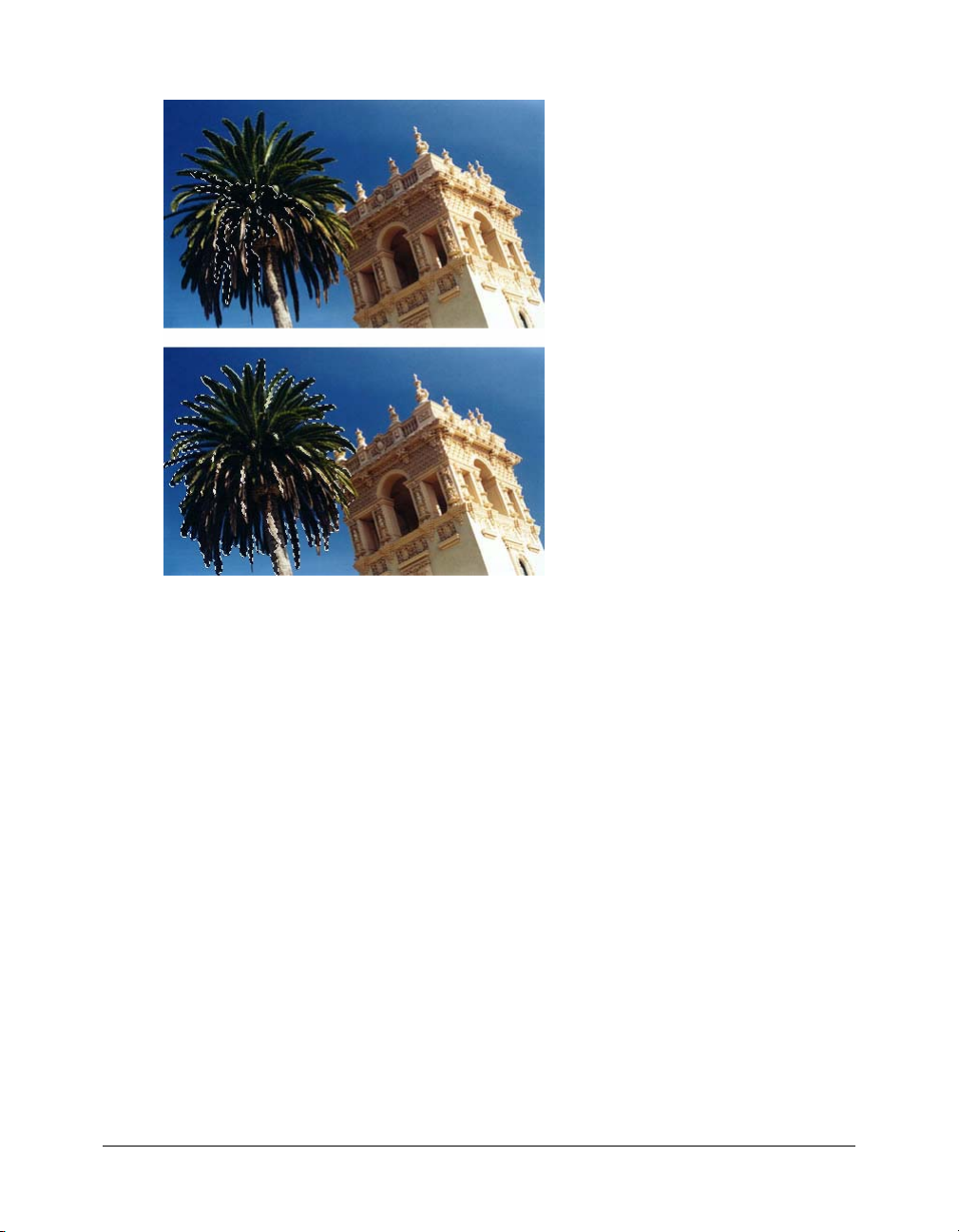
A marquee appears around the selected range of pixels.
Pixels selected with a lower tolerance (above), then a higher tolerance (below)
To select similar colors throughout the document:
1 Select an area of color with a marquee or lasso tool, or with the Magic Wand tool.
2 Choose Select > Select Similar.
One or more marquees show all areas containing the selected range of pixels, according to the
current Tolerance setting in the Property inspector for the Magic Wand tool.
Note: To adjust the tolerance for the Select Similar command, choose the Magic Wand tool and
then change the Tolerance setting in the Property inspector before using the command.
Removing a selection marquee
You can remove a selection marquee without affecting the document.
To remove a marquee, do one of the following:
• Draw another marquee.
• Click outside the current selection with a marquee or lasso tool.
• Press Escape.
• Choose Select > Deselect.
Selecting pixels 13
Page 14

Adjusting selection marquees
After selecting pixels with a marquee or lasso tool, you can edit or move the marquee border
without affecting the pixels beneath it. You can manually add pixels to or delete pixels from a
marquee border using modifier keys.
In addition, you can expand or contract the marquee border by a specified amount, select an
additional area of pixels around the existing marquee, or smooth the border of the marquee.
Moving a marquee
You can move a marquee to place it over a different area of pixels.
To move the marquee, do one of the following:
• Drag the marquee with a marquee or lasso tool or the Magic Wand tool.
• Use the arrow keys to nudge the marquee in 1-pixel increments.
• Press Shift and use the arrow keys to move the marquee in 10-pixel increments.
Adjusting a marquee selection with the Spacebar
You can easily reposition a marquee as you draw it by pressing the Spacebar while drawing.
To reposition a selection with the Spacebar:
1 Begin dragging to draw the selection.
2 Without releasing the mouse button, hold down the Spacebar.
3 Drag the marquee to another location on the canvas.
4 While still holding down the mouse button, release the Spacebar.
5 Continue dragging to draw the selection.
Adding to a pixel selection
After drawing a selection marquee with any bitmap selection tool, you can add to the selection
with the same tool or another bitmap selection tool.
To add to an existing pixel selection:
1 Choose any bitmap selection tool.
2 Hold down Shift and draw additional selection marquees.
3 Repeat steps 1 and 2 with any bitmap selection tool to continue adding to the selection.
Overlapping marquees join to form a contiguous marquee.
Subtracting pixels from a selection
You can subtract pixels from a selection, or punch out parts of a selection, defining pixel areas
inside the original marquee that will no longer be part of the selection.
To subtract pixels from a selection:
• Hold down Alt (Windows) or Option (Macintosh) and use a bitmap selection tool to select the
pixel area to be punched out.
14 Chapter 1: Selecting and Transforming Objects
Page 15

Creating a marquee from intersecting marquees
You can select pixels in an existing marquee by drawing a marquee that overlaps the original.
To select a pixel area defined by the intersection of two marquees:
1 Hold down Alt+Shift (Windows) or Option+Shift (Macintosh) while creating a new marquee
selection that overlaps the original marquee.
2 Release the mouse button.
Only the pixels in the intersection area of the two marquees are selected.
Using thumbnails and modifier keys to modify pixel selections
With a bitmap selected, you can create a pixel selection on that bitmap using the opacity of any
object or mask in the Layers panel. For more information about the Layers panel, see “Working
with layers” on page 129.
To create or replace a pixel selection on a selected bitmap using the opacity of an object:
1 In the Layers panel, position the pointer over the thumbnail of the object you want to use to
create the pixel selection.
2 Hold down Control (Windows) or Command (Macintosh).
The pointer changes to indicate you are about to select the alpha channel, or the opaque area,
of the object.
3 Click the thumbnail.
A new pixel selection is created on the selected bitmap.
To add to the current pixel selection:
• Control-Shift-click (Windows) or Command-Shift-click (Macintosh) the thumbnail of an
object in the Layers panel to add the shape of its opaque area to the current pixel selection.
Tip: When you position the pointer over the thumbnail and hold down the specified modifier keys,
the pointer indicates that you are about to add to the pixel selection.
To subtract from the current pixel selection:
• Control-Alt-click (Windows) or Command-Option-click (Macintosh) the thumbnail of
an object in the Layers panel to subtract the shape of its opaque area from the current
pixel selection.
Tip: When you position the pointer over the thumbnail and hold down the specified modifier keys,
the pointer indicates that you are about to subtract from the pixel selection.
To create a pixel selection on a selected bitmap from the intersection of overlapping objects:
1 Control-click (Windows) or Command-click (Macintosh) an object’s thumbnail to select its
alpha channel, or opaque area.
2 Control-Shift-Alt-click (Windows) or Command-Shift-Option-click (Macintosh)
another object.
A pixel selection is created on the selected bitmap from the intersection of the opaque areas of
the two overlapping objects.
Tip: When you position the pointer over the thumbnail and hold down the specified modifier keys,
the pointer indicates that you are about to create a pixel selection from the intersection of the
opaque areas of two overlapping objects.
Selecting pixels 15
Page 16

Creating an inverse pixel selection
Starting with a current pixel selection, you can create another pixel selection that selects all the
pixels that are not currently selected. You can use this method to select and then erase all pixels
surrounding the original selection, for example.
To create an inverse pixel selection:
1 Make a pixel selection using any bitmap selection tool.
2 Choose Select > Inverse Selection.
All pixels that were not in the original selection are now selected.
Feathering a pixel selection
Feathering creates a see-through effect for the selected pixels. When using the Feather command,
you can try out various feather amounts and view the results before deselecting the pixels. You can
also feather a selection by setting a feather amount in the Property inspector before using a
bitmap selection tool. For more information, see “Bitmap selection tool options” on page 11.
To feather a pixel selection:
1 Choose Select > Feather.
2 Enter a Feather amount in the Feather dialog box.
The selection marquee changes size to reflect the feather amount.
3 If necessary, change the number in the Feather dialog box to adjust the feather amount.
4 Click OK.
Tip: To view the appearance of the feathered selection without the surrounding pixels, choose
Select > Select Inverse, and then press Delete. You can then use the History panel or Edit > Undo
to try again.
Expanding or contracting a marquee
After you draw a marquee to select pixels, you can expand or contract its border.
To expand the border of a marquee:
1 After drawing the marquee, choose Select > Expand Marquee.
2 Enter the number of pixels by which you want to expand the border of the marquee, and
click OK.
To contract the border of a marquee:
1 After drawing the marquee, choose Select > Contract Marquee.
2 Enter the number of pixels by which you want to contract the border of the marquee, and
click OK.
16 Chapter 1: Selecting and Transforming Objects
Page 17
Selecting an area around an existing marquee
You can create an additional marquee to frame an existing marquee at a specified width. This lets
you create special graphics effects, such as feathering the edges of a pixel selection.
To select an area around an existing marquee:
1 After drawing a marquee, choose Select > Border Marquee.
2 Enter the width of the marquee that you want to place around the existing marquee, and
click OK.
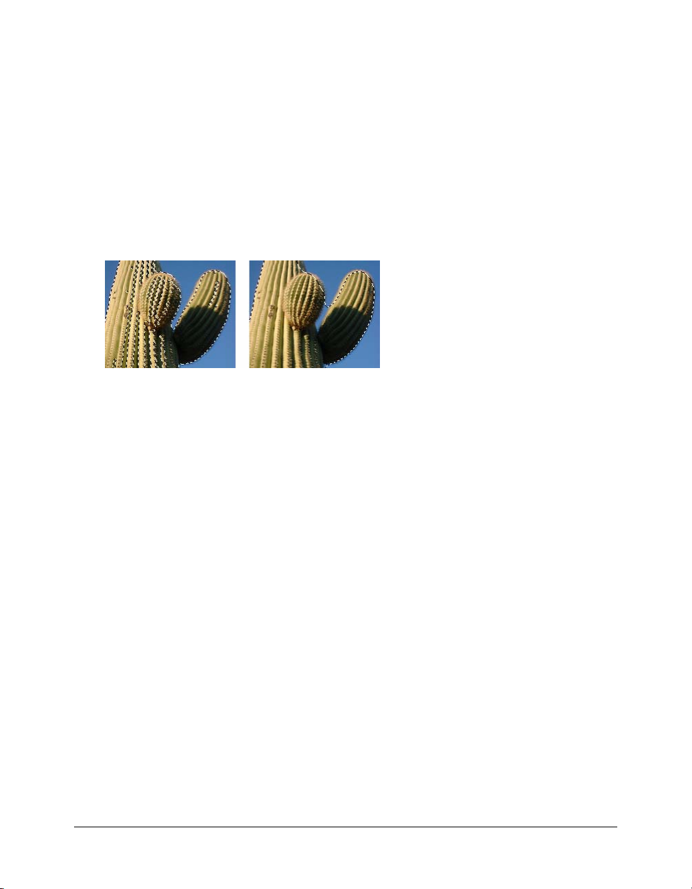
Smoothing the border of a marquee
You can eliminate excess pixels along the edges of a pixel selection. This is useful if excess pixels
appear along the border of a pixel selection or marquee after you use the Magic Wand tool.
A pixel selection before and after smoothing
To smooth the border of a marquee:
1 Choose Select > Smooth Marquee.
2 Enter a sample radius to specify the desired degree of smoothing, and click OK.
Transferring a marquee selection
You can transfer a marquee selection from one bitmap to another bitmap object on the same layer
or one on a different layer. You can also transfer the marquee selection to a mask.
To transfer a marquee selection to another bitmap object:
1 Make a selection by drawing the marquee.
2 In the Layers panel, select a different bitmap object on the same layer or an object on a
different layer.
The marquee is transferred to that object.
Note: Fireworks treats masks and masked objects as separate objects. For more information on
masks, see “Masking images” on page 134.
Selecting pixels 17
Page 18

Saving and restoring marquee selections
You can save the size, shape, and location of a selection to reapply later.
To save a marquee selection:
• Choose Select > Save Bitmap Selection.
To restore a marquee selection:
• Choose Select > Restore Bitmap Selection.
Note: You can save only one selection at a time.
Creating and moving a floating pixel selection
When you drag a marquee to a new location, the marquee itself moves. If you want to move, edit,
cut, or copy a selection of pixels, you must first make the pixels a floating selection.
To create a floating pixel selection:
1 Make a pixel selection with a bitmap selection tool.
2 Do one of the following:
■ Hold down Control (Windows) or Command (Macintosh) and drag the selection using any
tool from the Bitmap section of the Tools panel.
■ Choose the Pointer tool and drag the selection.
To move a floating selection, do one of the following:
• Drag the floating selection with the Pointer tool or any bitmap selection tool.
• If a nonselection bitmap tool is active, hold down Control (Windows) or Command
(Macintosh) and drag the floating selection.
• Use the arrow keys or Shift+arrow keys.
When you deselect the floating pixel selection or choose any vector or web tool, the floating
selection becomes part of the current bitmap object.
Inserting a new bitmap by cutting or copying
You can insert a new bitmap based on a pixel selection into the current layer of a document by
cutting or copying the selected pixels.
To insert a new bitmap by cutting and pasting a pixel selection:
1 Select an area of pixels using a pixel selection tool.
2 Choose Edit > Insert > Bitmap via Cut.
A new bitmap object based on the pixel selection is created in the current layer, and the
selected pixels are removed from the original bitmap object. In the Layers panel, a thumbnail
of the new bitmap appears in the current layer, above the object from which it was cut.
18 Chapter 1: Selecting and Transforming Objects
Page 19

To insert a new bitmap by copying and pasting a pixel selection:
1 Select an area of pixels using a pixel selection tool.
2 Choose Edit > Insert > Bitmap via Copy.
A new bitmap object based on the pixel selection is created in the current layer, and the
selected pixels remain in the original bitmap object. In the Layers panel, a thumbnail of the
new bitmap appears in the current layer, above the object from which it was copied.
Editing selected objects
Fireworks gives you a number of ways to edit selected objects: you can move objects on the canvas
or from application to application, you can replicate objects with the Clone and Duplicate
commands, or you can remove objects from the workspace altogether.
To move a selection, do one of the following:
• Drag it with the Pointer, Subselection, or Select Behind tool.
• Press any arrow key to move the selection in 1-pixel increments.
• Hold down Shift while pressing any arrow key to move the selection in 10-pixel increments.
• In the Property inspector, enter the X and Y coordinates for the location of the top left corner
of the selection.
• Enter the object’s x and y coordinates in the Info panel. If the X and Y boxes aren’t visible, drag
the bottom edge of the panel.
To move or copy selected objects by pasting:
1 Select an object or multiple objects.
2 Choose Edit > Cut or Edit > Copy.
3 Choose Edit > Paste.
To duplicate one or more selected objects:
• Choose Edit > Duplicate.
As you repeat the command, duplicates of the selected object appear in a cascading arrangement
from the original, 10 pixels lower and 10 pixels to the right of the previous duplicate. The most
recently duplicated object becomes the selected object.
Note: You cannot use the Duplicate or Clone commands with bitmap selections. Use the
Subselection tool or Rubber Stamp tool to duplicate parts of a bitmap image. For more information
about using the Subselection tool, see the following procedures. For more information about using
the Rubber Stamp tool, see “Retouching bitmaps” on page 34.
Editing selected objects 19
Page 20

To duplicate a selected object by dragging:
• Alt-drag (Windows) or Option-drag (Macintosh) the object using the Pointer tool.
To duplicate a pixel selection, do one of the following:
• Drag the pixel selection using the Subselection tool.
• Alt-drag (Windows) or Option-drag (Macintosh) the object using the Pointer tool.
To clone a selection:
• Choose Edit > Clone.
The clone of the selection is stacked precisely in front of the original and becomes the selected
object.
Note: To move a selected clone away from the original with pixel-by-pixel precision, use the arrow
keys or Shift+arrow keys. This is a convenient way to maintain a specific distance between clones
or maintain the vertical or horizontal alignment of the clones.
To delete selected objects, do one of the following:
• Press Delete or Backspace.
• Choose Edit > Clear.
• Choose Edit > Cut.
• Right-click (Windows) or Control-click (Macintosh) the object and choose Edit > Cut from
the context menu.
To cancel or deselect a selection, do one of the following:
• Choose Select > Deselect.
• Click anywhere in the image outside of the selected area if you are using the Marquee, Oval
Marquee, or Lasso tool.
• Press Escape.
20 Chapter 1: Selecting and Transforming Objects
Page 21
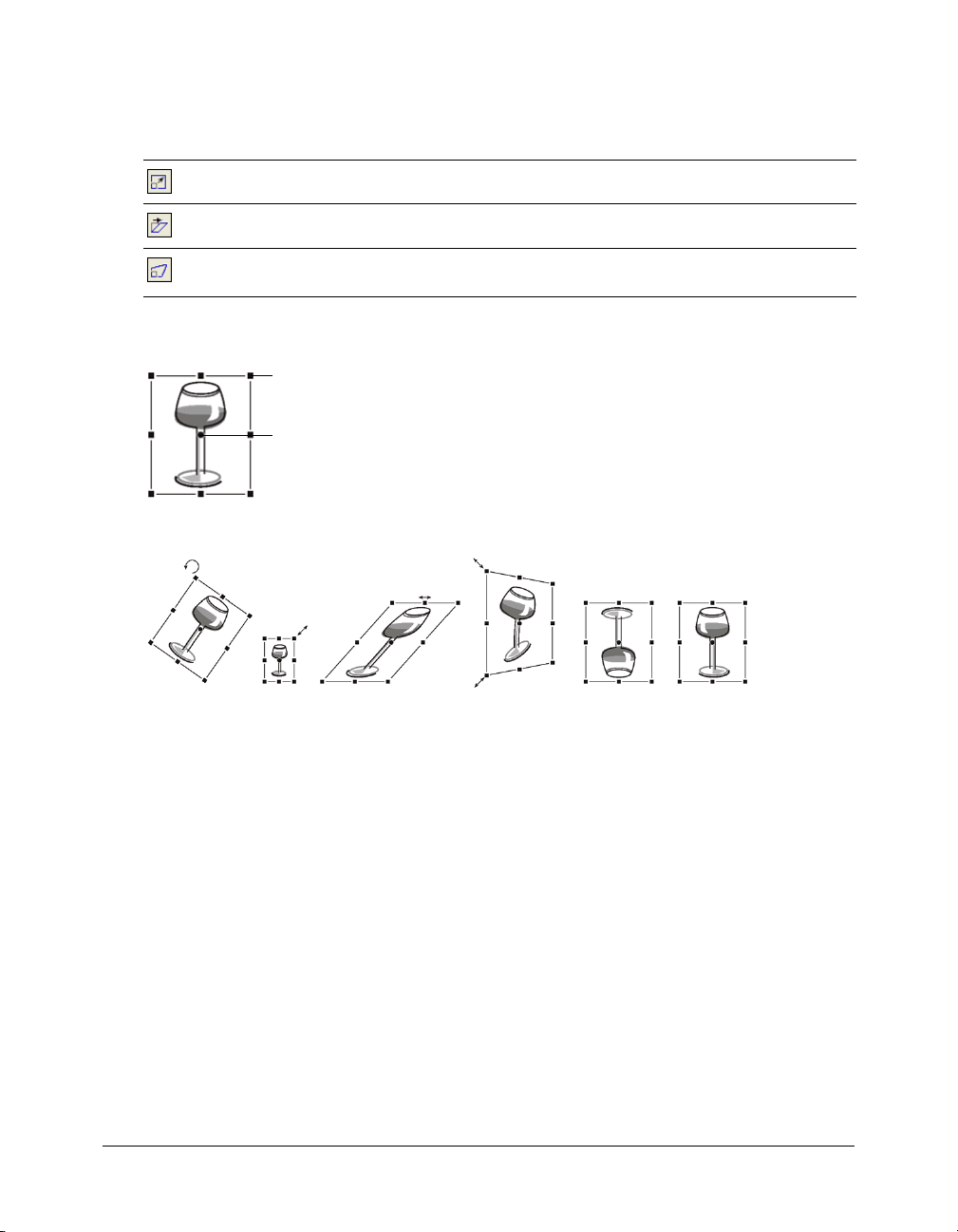
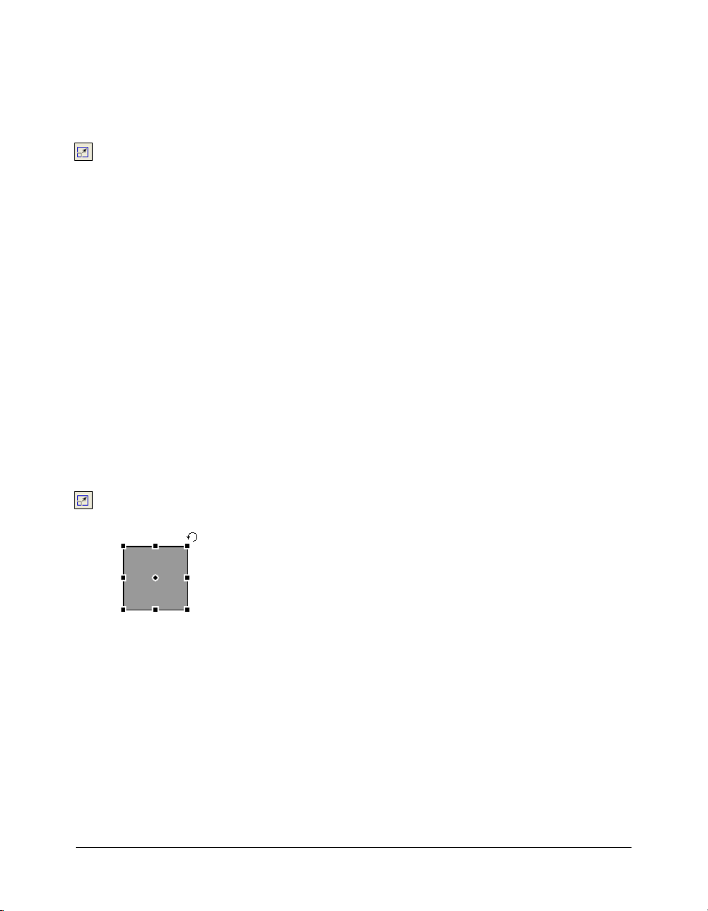
Transforming and distorting selected objects and selections
You can transform a selected object or group, or a pixel selection, using the Scale, Skew, and
Distort tools and menu commands:
Scale enlarges or reduces an object.
Skew slants an object along a specified axis.
Distort moves the sides or corners of an object in the direction you drag a selection handle
while the tool is active. This is helpful in creating a 3D look.
When you choose any transformation tool or Transform menu command, Fireworks displays
transform handles around selected objects.
Transform handles
Center point
Original object
Object rotated, scaled, skewed, distorted, and flipped vertically and horizontally
To transform selected objects using the transform handles:
1 Choose a transformation tool.
As you move the pointer on or near the selection handles, the pointer changes to indicate the
current transformation.
2 Do one of the following to transform the objects:
■ Place the pointer near a corner point and then drag to rotate.
■ Drag a transform handle to transform according to the active transformation tool.
3 Double-click inside the window or press Enter to apply your changes.
Transforming and distorting selected objects and selections 21
Page 22
Resizing (scaling) objects
Scaling an object enlarges or reduces it horizontally, vertically, or in both directions.
To scale a selected object:
1 Do one of the following to display the transform handles:
■ Choose the Scale tool.
■ Choose Modify > Transform > Scale.
2 Drag the transform handles:
■ To scale the object both horizontally and vertically, drag a corner handle. Proportions are
constrained if you press the Shift key as you scale.
■ To scale the object horizontally or vertically, drag a side handle.
■ To scale the object from the center, press Alt while dragging any handle.
Note: You can also resize selected objects by entering dimensions in the Property inspector.
For more information, see “Transforming objects numerically” on page 24.
Rotating objects
When rotated, an object pivots on its center point. You rotate an object by choosing a preset angle
or by placing the pointer outside an object’s transform handles to display the rotation pointer
before you drag.
Note: You can also rotate the document canvas. For more information, see Fireworks Help.
To rotate a selected object 90° or 180°:
• Choose Modify > Transform and choose a Rotate command from the submenu.
To rotate a selected object by dragging:
1 Choose any transformation tool.
2 Move the pointer outside the object until the rotation pointer appears.
3 Drag to rotate the object.
Tip: To constrain rotation to 15° increments relative to the horizon, Shift-drag the pointer.
4 Double-click inside the window or press Enter to apply your changes.
To relocate the axis of rotation:
• Drag the center point away from the center.
To reset the axis of rotation to the center of the selection, do one of the following:
• Double-click the center point
• Press Escape to deselect the object, then select it again.
22 Chapter 1: Selecting and Transforming Objects
Page 23

Flipping objects
You can flip an object across its vertical or horizontal axis without moving its relative position on
the canvas.
To flip a selected object:
• Choose Modify > Transform > Flip Horizontal or Flip Vertical.
Skewing objects
Skewing an object transforms it by slanting it along the horizontal or vertical axis, or both axes.
To skew a selected object:
1 Do one of the following to display the transform handles:
■ Choose the Skew tool.
■ Choose Modify > Transform > Skew.
2 Drag a handle to skew the object.
3 Double-click inside the window or press Enter to remove the transform handles.
To achieve the illusion of perspective:
• Drag a corner point.
Distorting objects
You change the size and proportions of an object by dragging a selection handle with the
Distort tool.
To distort a selected object:
1 Do one of the following to display the transform handles:
■ Choose the Distort tool.
■ Choose Modify > Transform > Distort.
2 Drag a handle to distort the object.
3 Double-click inside the window or press Enter to apply your changes.
Transforming and distorting selected objects and selections 23
Page 24

Transforming objects numerically
Instead of dragging to scale, resize, or rotate an object, you can transform it by entering
specific values.
To resize selected objects using the Property inspector or Info panel:
• Enter new width (W) or height (H) measurements.
Note: If the W and H boxes aren’t visible in the Property inspector, click the expander arrow to see
all properties.
To scale or rotate selected objects using Numeric Transform:
1 Choose Modify > Transform > Numeric Transform.
The Numeric Transform dialog box opens.
2 From the pop-up menu, choose the type of transformation to perform on the current selection:
Scale, Resize, or Rotate.
3 Choose Constrain Proportions to maintain horizontal and vertical proportions when scaling or
resizing a selection.
4 Choose Scale Attributes to transform the fill, stroke, and effects of the object along with the
object itself.
5 Deselect Scale Attributes to transform the path only.
6 Type numeric values to transform the selection, then click OK.
Viewing transformation information in the Info panel
The Info panel lets you view numerical transformation information for the currently selected
object. The information updates as you edit the object.
• For scaling and free transformations, the Info panel shows the width (W) and height (H) of the
original object before transformation and the percentage of increase or decrease in width and
height during the transformation.
• For skewing and distorting, the Info panel shows the skew angle in one-degree increments and
the X and Y pointer coordinates during the transformation.
To view transformation information as you transform a selection:
• Choose Window > Info.
Organizing objects
When working with multiple objects in a single document, you can use several techniques to
organize the document:
• You can group individual objects to treat them as one or protect each object’s relationship to
the others in the group.
• You can arrange objects behind or in front of other objects. The way objects are arranged is
called the stacking order.
• You can align selected objects to an area of the canvas or to a vertical or horizontal axis.
24 Chapter 1: Selecting and Transforming Objects
Page 25
Grouping objects
You can group individual selected objects and then manipulate them as if they were a single
object. For example, after drawing the petals of a flower as individual objects, you can group them
to select and move the entire flower as a single object.
You can edit groups without ungrouping them. You can select an individual object in a group for
editing without ungrouping the objects. You can also ungroup the objects at any time.
To group two or more selected objects:
• Choose Modify > Group.
To ungroup selected objects:
• Choose Modify > Ungroup.
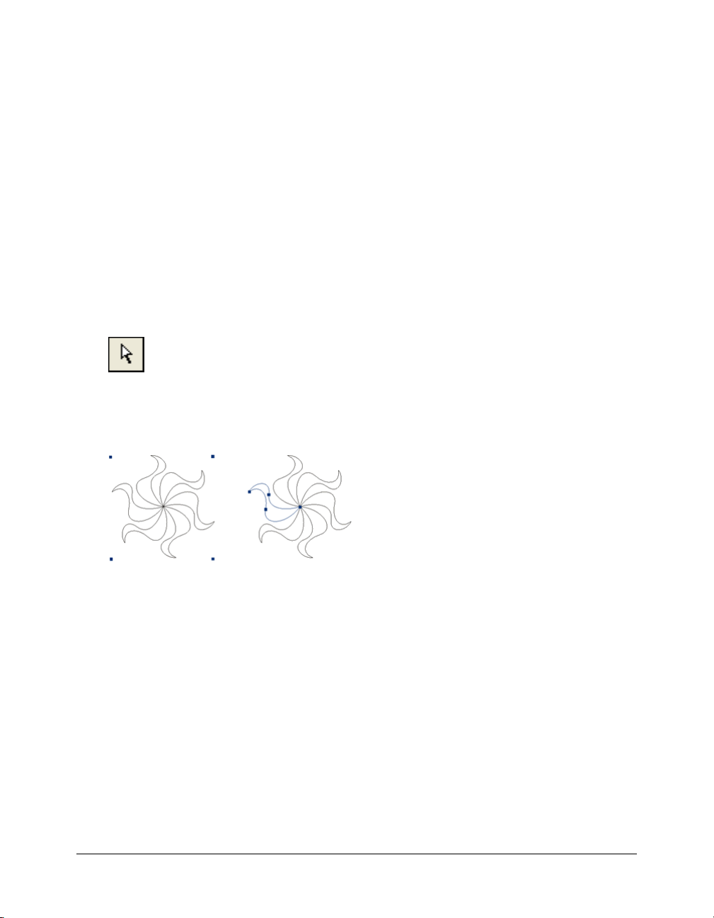
Selecting objects within groups
To work with individual objects within a group, you can either ungroup the objects or use the
Subselection tool to select individual objects while leaving the group intact.
Subselection tool
Modifying the attributes of a subselected object changes only the subselected object, not the
entire group. Moving a subselected object to another layer removes the object from the group.
Subselecting an object within a group
To select an object that is part of a group:
• Choose the Subselection tool and click the object or drag a selection area around it. To add
objects to or remove them from the selection, hold down Shift as you click or drag.
To select the group that contains a subselected object, do one of the following:
• Right-click (Windows) or Control-click (Macintosh) anywhere in the group and choose
Select > Superselect from the context menu.
• Choose Select > Superselect.
To select all objects within a selected group, do one of the following:
• Right-click (Windows) or Control-click (Macintosh) anywhere on the group and choose
Select > Subselect from the context menu.
• Choose Select > Subselect.
Organizing objects 25
Page 26

Stacking objects
Within a layer, Fireworks stacks objects based on the order in which they were created, placing the
most recently created object on the top of the stack. The stacking order of objects determines how
they appear when they overlap.
Layers also affect the stacking order. For example, suppose a document has two layers named
Layer 1 and Layer 2. If Layer 1 is listed below Layer 2 on the Layers panel, then everything on
Layer 2 appears in front of everything on Layer 1. You can change the order of layers by dragging
the layer in the Layers panel to a new position. For more information, see “Organizing layers”
on page 131.
To change the stacking order of a selected object or group within a layer:
• Choose Modify > Arrange > Bring to Front or Send to Back to move the object or group to the
top or bottom of the stacking order.
• Choose Modify > Arrange > Bring Forward or Send Backward to move the object or group up
or down one position in the stacking order.
If more than one object or group is selected, the objects move in front of or behind all unselected
objects while maintaining their order relative to one another.
Aligning objects
The Align commands in the Modify menu give you a wide range of arrangement options,
allowing you to do any of the following:
Align objects along a horizontal or vertical axis.
Align selected objects vertically along their right edge, center, or left edge, or horizontally along
their top edge, center, or bottom edge.
Note: Edges are determined by the bounding boxes enclosing each selected object.
Distribute selected objects
You can apply one or more Align commands to selected objects.
To align selected objects, do one of the following:
so that their centers or edges are evenly spaced.
• Choose Modify > Align > Left to align the objects to the leftmost selected object.
• Choose Modify > Align > Center Vertical to align the center points of the objects along a
vertical axis.
• Choose Modify > Align > Right to align the objects to the rightmost selected object.
• Choose Modify > Align > Top to align the objects to the topmost selected object.
• Choose Modify > Align > Center Horizontal to align the center points of the objects along a
horizontal axis.
• Choose Modify > Align > Bottom to align the objects to the bottommost selected object.
To evenly distribute the widths or heights of three or more selected objects:
• Choose Modify > Align > Distribute Widths or Modify > Align > Distribute Heights.
26 Chapter 1: Selecting and Transforming Objects
Page 27

About arranging objects among layers
The Layers panel offers another dimension of organizational control. You can move selected
objects from one layer to another by dragging the object thumbnail or the blue selection indicator
in the Layers panel to another layer. For more information, see “Organizing layers” on page 131.
Organizing objects 27
Page 28

28 Chapter 1: Selecting and Transforming Objects
Page 29

CHAPTER 2
Working with Bitmaps
Bitmaps are graphics composed of small colored squares called pixels, which combine like the
tiles of a mosaic to create an image. Examples of bitmap graphics include photographs,
scanned images, and graphics created from paint programs. They are sometimes referred to
as raster images.
Macromedia Fireworks MX 2004 combines the functionality of photo-editing, vector-drawing,
and painting applications. You can create bitmap images by drawing and painting with bitmap
tools, by converting vector objects to bitmap images, or by opening or importing images.
Fireworks has a powerful set of Live Effects for tone and color adjustment, as well as a number of
ways to retouch your bitmap images, including cropping, feathering, and duplicating or cloning
images. In addition, Fireworks has a set of image-retouching tools—Blur, Sharpen, Dodge, Burn,
and Smudge.
For information on methods for selecting and transforming images and pixel areas, see
Fireworks Help.
Working with bitmaps
The Bitmap section of the Tools panel contains bitmap selection and editing tools. To edit the
pixels of a bitmap in your document, you can choose a tool from the Bitmap section. Unlike in
previous versions of Fireworks, you do not need to deliberately switch between bitmap mode and
vector mode, but you can still work with bitmaps, vector objects, and text. Switching to the
appropriate mode is as simple as choosing a vector or bitmap tool from the Tools panel.
Note: Previous versions of Fireworks display a striped border around the canvas to indicate that
Fireworks is in bitmap mode. If you prefer to see the familiar striped border when working with
bitmaps, you can choose Bitmap Options > Display Striped Border from the Edit category of the
Preferences dialog box.
29
Page 30

Creating bitmap objects
You can create bitmap graphics by using the Fireworks bitmap drawing and painting tools, by
cutting or copying and pasting pixel selections, or by converting a vector image into a bitmap
object. Another way to create a bitmap object is to insert an empty bitmap image in your
document and then draw, paint, or fill it.
When you create a new bitmap object, it is added to the current layer. In the Layers panel with
layers expanded, you can see a thumbnail and name for each bitmap object under the layer on
which it resides. Although some bitmap applications consider each bitmap object a layer,
Fireworks organizes bitmap objects, vector objects, and text as separate objects that reside on
layers. For more information, see “Working with layers” on page 129.
To create a new bitmap object:
1 Choose the Brush or Pencil tool from the Bitmap section of the Tools panel.
2 Paint or draw with the Brush or Pencil tool to create bitmap objects on the canvas.
A new bitmap object is added to the current layer in the Layers panel. For more information
on using the Pencil or Brush tools, see “Drawing, painting, and editing bitmap objects”
on page 31.
You can create a new empty bitmap, and then draw or paint pixels in the empty bitmap.
To create an empty bitmap object, do one of the following:
• Click the New Bitmap Image button in the Layers panel.
• Choose Edit > Insert > Empty Bitmap.
• Draw a selection marquee, starting in a blank area of the canvas, and fill it. For more
information, see “Creating pixel selection marquees” on page 11.
An empty bitmap is added to the current layer in the Layers panel. If the empty bitmap is
deselected before any pixels have been drawn, imported, or otherwise placed on it, the empty
bitmap object automatically disappears from the Layers panel and the document.
To cut or copy pixels and paste them as a new bitmap object:
1 Make a pixel selection using the Marquee tool, Lasso tool, or Magic Wand tool.
For more information, see “Selecting pixels” on page 10.
2 Do one of the following:
■ Choose Edit > Cut, then Edit > Paste.
■ Choose Edit > Copy, then Edit > Paste.
■ Choose Edit > Insert > Bitmap via Copy to copy the current selection into a new bitmap.
■ Choose Edit > Insert > Bitmap via Cut to cut the current selection for placement into a
new bitmap.
The selection appears in the Layers panel as an object on the current layer.
Note: You can also Right-click (Windows) or Control-click (Macintosh) a pixel marquee selection
and choose a cut or copy option from the context menu. For more information about the Bitmap
via Cut and Bitmap via Copy options, see “Inserting a new bitmap by cutting or copying”
on page 18.
30 Chapter 2: Working with Bitmaps
Page 31

To convert selected vector objects to a bitmap image, do one of the following:
• Choose Modify > Flatten Selection.
• Choose Flatten Selection from the Layers panel Options menu.
A vector-to-bitmap conversion is irreversible, except when Edit > Undo or undoing actions in
the History panel is still an option. Bitmap images cannot be converted to vector objects.
Drawing, painting, and editing bitmap objects
The Bitmap section of the Tools panel contains tools for selecting, drawing, painting, and editing
pixels in a bitmap image.
Drawing bitmap objects
You can use the Pencil tool to draw 1-pixel lines, either freehand lines or constrained, straight
lines, much as you use a real pencil, with or without a ruler, to draw hard-edged lines. You can
also zoom in on a bitmap and use the Pencil tool to edit individual pixels.
To draw an object with the Pencil tool:
1 Choose the Pencil tool.
2 Set tool options in the Property inspector:
Anti-aliased smooths the edges of the lines you draw.
Auto Erase uses the fill color when the Pencil tool is clicked over the stroke color.
Preserve Transparency restricts the Pencil tool to drawing only in existing pixels, not in
transparent areas of a graphic.
3 Drag to draw. Shift-drag to constrain the path to a horizontal, vertical, or diagonal line.
Painting bitmap objects
You can use the Brush tool to paint a brush stroke using the color in the Stroke Color box, or you
can use the Paint Bucket tool to change the color of selected pixels to the color in the Fill Color
box. With the Gradient tool, you can fill bitmap or vector objects with a combination of colors in
adjustable patterns.
To paint an object with the Brush tool:
1 Choose the Brush tool.
2 Set the stroke attributes in the Property inspector.
3 Drag to paint.
For more information about setting Brush tool options, see “Working with strokes”
on page 106.
Drawing, painting, and editing bitmap objects 31
Page 32

To change the color of pixels to the color in the Fill Color box:
1 Choose the Paint Bucket tool.
2 Choose a color in the Fill Color box.
3 Set the tolerance value in the Property inspector.
Note: The tolerance determines how similar in color pixels must be to be filled. A low tolerance
value fills pixels with color values similar to the pixel you click. A high tolerance fills pixels with a
broader range of color values.
4 Click the image.
All pixels within the tolerance range change to the fill color.
To apply a gradient fill to a pixel selection:
1 Make the selection.
2 Choose the Gradient tool.
3 Set the fill attributes in the Property inspector.
4 Click the pixel selection to apply the fill.
The Paint Bucket and Gradient tools can also fill selected vector objects. For more information
about creating, applying, and editing gradient fills, see “Working with fills” on page 110.
Sampling a color to use as a stroke or fill color
With the Eyedropper tool, you can sample color from an image to designate a new stroke or fill
color. You can sample the color of a single pixel, an average of color values within a 3-by-3-pixel
area, or an average of color values within a 5-by-5-pixel area.
To sample a stroke or fill color:
1 If the correct attribute is not already active, do one of the following:
■ Click the stroke icon next to the Stroke Color box in the Tools panel to make it the active
attribute.
■ Click the fill icon next to the Fill Color box in the Tools panel to make it the active
attribute.
Note: Do not click the color box itself. If you do, the eyedropper pointer that appears is not the
Eyedropper tool. For information on the color box eyedropper pointer, see “Sampling colors from
a color pop-up window” on page 105.
2 Open a Fireworks document or any file that Fireworks can open. For more information, see
Chapter 9, “Slices, Rollovers, and Hotspots,” on page 167.
3 Choose the Eyedropper tool from the Bitmap section of the Tools panel. Set the Color
Averaging Sample setting in the Property inspector:
1-pixel creates a stroke or fill color from a single pixel.
3x3 pixels creates a stroke or fill color from the average of color values in a 3-by-3-pixel area.
5x5 pixels creates a stroke or fill color from the average of color values in a 5-by-5-pixel area.
4 Click the Eyedropper tool anywhere in the document.
The sampled color appears in all Stroke Color or Fill Color boxes throughout Fireworks.
32 Chapter 2: Working with Bitmaps
Page 33
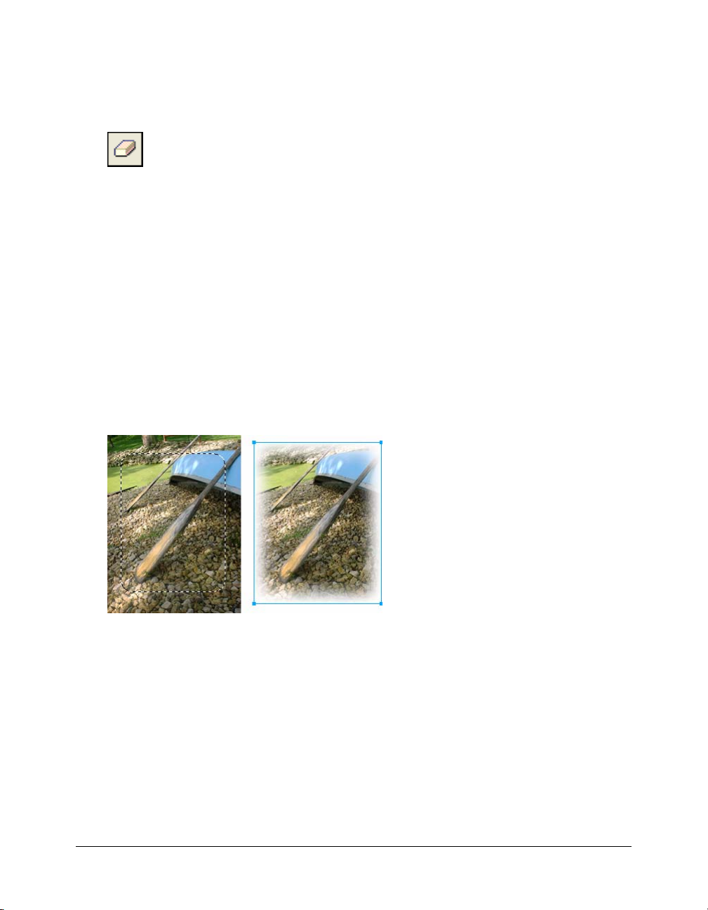
Erasing bitmap objects
You can use the Eraser tool to remove pixels. By default, the Eraser tool pointer represents the size
of the current eraser, but you can change the size and appearance of the pointer in the Preferences
dialog box. For more information, see “Editing preferences” on page 282.
Eraser tool
To erase pixels in a selected bitmap object or pixel selection:
1 Choose the Eraser tool.
2 In the Property inspector, choose the round or square eraser shape.
3 Drag the Edge slider to set the softness of the eraser’s edge.
4 Drag the Size slider to set the size of the eraser.
5 Drag the Eraser Opacity slider to set the degree of opacity.
6 Drag the Eraser tool over the pixels you want to erase.
Feathering pixel selections
Feathering blurs the edges of a pixel selection and helps the selected area blend with
the surrounding pixels. Feathering is useful when you copy a selection and paste it onto
another background.
To feather the edges of a pixel selection as you make a pixel selection:
1 Choose a bitmap selection tool from the Tools panel.
2 Choose Feather from the Edge pop-up menu in the Property inspector.
3 Drag the slider to set the number of pixels you want to blur along the edge of the selection.
4 Make a selection.
To feather the edges of a pixel selection from the menu bar:
1 Choose Select > Feather.
2 Type a value in the Feather Selection dialog box to set the feather radius, and click OK.
The radius value determines the number of pixels that are feathered on each side of the
selection border.
Drawing, painting, and editing bitmap objects 33
Page 34

Retouching bitmaps
Fireworks provides a wide range of tools to help you retouch your images. You can alter an image’s
size, reduce or sharpen its focus, or copy and “stamp” a part of it to another area.
The Rubber Stamp tool lets you copy or clone one area of an image to another.
The Blur tool decreases the focus of selected areas in an image.
The Smudge tool picks up color and pushes it in the direction that you drag in an image.
The Sharpen tool sharpens areas in an image.
The Dodge tool lightens parts of an image.
The Burn tool darkens parts of an image.
The Red-eye Removal tool reduces the appearance of red eye in photos
The Replace Color tool paints over one color with another color
Cloning pixels
The Rubber Stamp tool clones an area of a bitmap image so that you can stamp it elsewhere in
the image. Cloning pixels is useful when you want to fix a scratched photograph or remove dust
from an image; you can copy a pixel area of a photo and replace the scratch or dust spot with the
cloned area.
To clone portions of a bitmap image:
1 Choose the Rubber Stamp tool.
2 Click an area to designate it as the source, or the area you want to clone.
The sampling pointer becomes a cross-hair pointer.
Note: To designate a different area of pixels to clone, you can Alt-click (Windows) or Option-click
(Macintosh) another area of pixels to designate it as the source.
3 Move to a different part of the image and drag the pointer.
You will see two pointers. The first one, the source of the cloning, is in the shape of a cross hair.
For more information, see “Editing preferences” on page 282.
Depending upon the brush preferences you’ve selected, the second pointer is a rubber stamp, a
cross hair, or a blue circle. As you drag the second pointer, pixels beneath the first pointer are
copied and applied to the area beneath the second.
34 Chapter 2: Working with Bitmaps
Page 35

To set Rubber Stamp tool options:
1 Choose the Rubber Stamp tool.
2 Choose from among the following options in the Property inspector:
Size determines the size of the stamp.
Edge determines the softness of the stroke (100% is hard; 0% is soft).
Source Aligned affects the sampling operation. When Source Aligned is selected, the
sampling pointer moves vertically and horizontally in alignment with the second. When
Source Aligned is deselected, the sample area is fixed, regardless of where you move and click
the second pointer.
Use Entire Document samples from all objects on all layers. When this option is deselected,
the Rubber Stamp tool samples from the active object only.
Opacity determines how much of the background can be seen through the stroke.
Blend Mode affects how the cloned image affects the background.
To duplicate a pixel selection, do one of the following:
• Drag the pixel selection with the Subselection tool.
• Alt-drag (Windows) or Option-drag (Macintosh) the pixel selection using the Pointer tool.
Blurring, sharpening, and smudging pixels
The Blur and Sharpen tools affect the focus of pixels. The Blur tool lets you emphasize or
deemphasize parts of an image by selectively blurring the focus of elements, much as a
photographer controls depth of field. The Sharpen tool can be useful for repairing scanning
problems or out-of-focus photographs. The Smudge tool lets you gently blend colors, as when
creating a reflection of an image.
To blur or sharpen an image:
1 Choose the Blur or Sharpen tool.
2 Set brush options in the Property inspector:
Size sets the size of the brush tip.
Edge specifies the softness of the brush tip.
Shape sets a round or square brush tip shape.
Intensity sets the amount of blurring or sharpening.
3 Drag the tool over the pixels to be sharpened or blurred.
Tip: Hold down Alt (Windows) or Option (Macintosh) to change from one tool behavior to
the other.
Retouching bitmaps 35
Page 36

To smudge colors in an image:
1 Choose the Smudge tool.
2 Set the tool options in the Property inspector:
Size specifies the size of the brush tip.
Shape sets a round or square brush tip shape.
Edge specifies the softness of the brush tip.
Pressure sets the intensity of the stroke.
Smudge Color allows you to smudge using a specified color at the beginning of each stroke.
If this option is deselected, the tool uses the color under the tool pointer.
Use Entire Document smudges using color data from all objects on all layers. If this option is
deselected, the Smudge tool uses colors from the active object only.
3 Drag the tool over the pixels to be smudged.
Lightening and darkening pixels
You use the Dodge or Burn tool to lighten or darken parts of an image, respectively. This is
similar to the darkroom technique of increasing or decreasing light exposure as the photograph
is developed.
To lighten or darken parts of an image:
1 Choose the Dodge tool to lighten parts of an image or the Burn tool to darken parts of an image.
2 Set the brush options in the Property inspector:
Size sets the size of the brush tip.
Shape sets a round or square brush tip shape.
Edge sets the softness of the brush tip.
3 Set the exposure in the Property inspector.
The exposure ranges from 0% to 100%. For a lessened effect, specify a lower percentage value;
for a stronger effect, specify a higher value.
4 Set the range in the Property inspector:
Shadows changes mainly the dark portions of the image.
Highlights changes mainly the light portions of the image.
Midtones changes mainly the middle range per channel in the image.
5 Drag over the part of the image you want to lighten or darken.
Hold down Alt (Windows) or Option (Macintosh) as you drag the tool to temporarily switch
from the Dodge tool to the Burn tool or from the Burn tool to the Dodge tool.
36 Chapter 2: Working with Bitmaps
Page 37
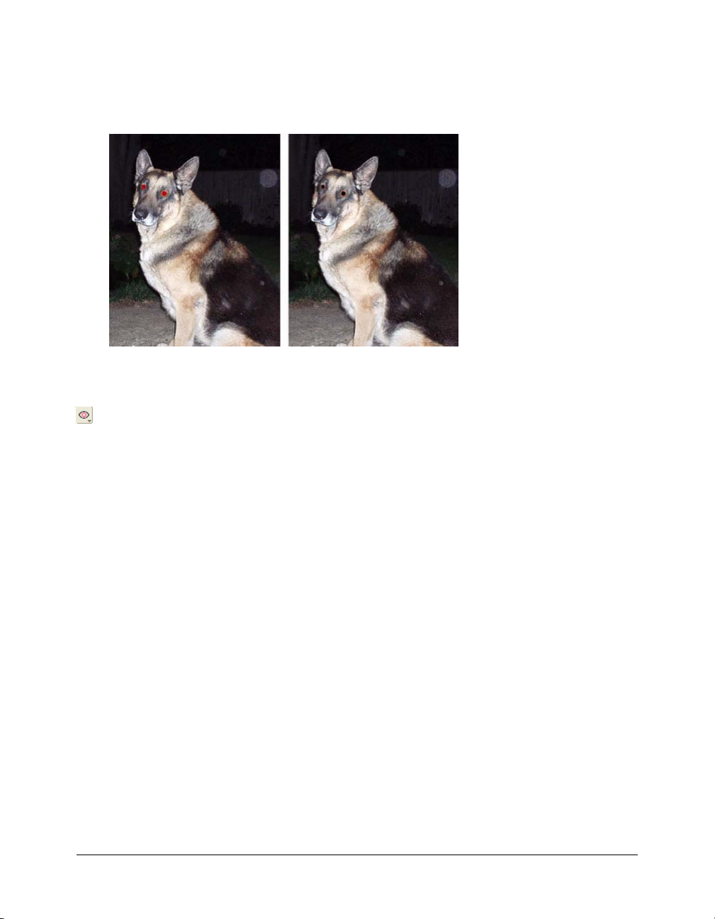
Removing red-eye from photos
In some photographs, the subjects’ pupils are an unnatural shade of red. You can use the Red-eye
Removal tool to correct this red-eye effect. The Red-eye Removal tool paints red areas of a
photograph only, replacing reddish colors with grays and blacks.
Original photograph; after using the Red-eye Removal tool
To correct the red-eye effect in a photograph:
1 Choose the Red-eye Removal tool from its pop-up menu.
2 Set the stroke attributes in the Property inspector:
Size sets the size of the brush tip.
Shape sets a round or square brush tip shape.
Tolerance determines the range of hues to replace (0 replaces only red; 255 replaces all hues
that contain red).
Strength sets the darkness of the grays used to replace reddish colors.
3 Drag or click the red pupils in the photograph.
Retouching bitmaps 37
Page 38
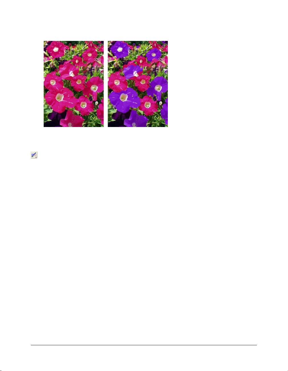
Replacing colors
The Replace Color tool lets you select a color and paint over that color with a different color.
Original photograph; after using the Replace Color tool
To replace one color with another:
1 Choose the Replace Color tool from its pop-up menu.
2 Click the Change color well in the Property inspector to select the color probe, and choose a
color from the pop-up menu, or click in the image to choose the color you want to replace.
3 Click the To color well in the Property inspector to select the color probe, then choose a color
from the pop-up menu, or click in the image to choose the color you want to use as a
replacement.
4 Set the other stroke attributes in the Property inspector:
Size sets the size of the brush tip.
Shape sets a round or square brush tip shape.
Tolerance determines the range of colors to replace (0 replaces only the To color; 255 replaces
all colors similar to the To color).
Strength determines how much of the Change color is replaced.
Colorize replaces the Change color with the To color. Deselect Colorize to tint the Change
color with the To color, leaving some of the Change color intact.
5 Drag the tool over the color you want to replace.
38 Chapter 2: Working with Bitmaps
Page 39
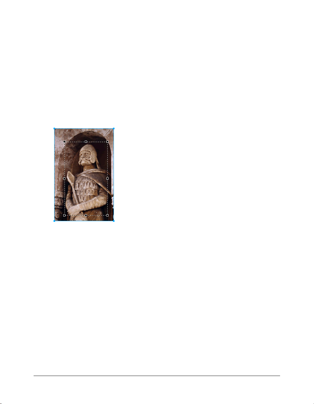
Cropping a selected bitmap
You can isolate a single bitmap object in a Fireworks document and crop only that bitmap object,
leaving other objects on the canvas intact.
To crop a bitmap image without affecting other objects in the document:
1 Select a bitmap object by clicking the object on the canvas or by clicking its thumbnail in the
Layers panel, or draw a selection marquee using a bitmap selection tool.
2 Choose Edit > Crop Selected Bitmap.
The crop handles appear around the entire selected bitmap or around the selection marquee, if
you drew one in step 1.
3 Adjust the crop handles until the bounding box surrounds the area of the bitmap image that
you want to keep.
Note: To cancel a crop selection, press Escape.
Bounding box
4 Double-click inside the bounding box or press Enter to crop the selection.
Every pixel in the selected bitmap outside the bounding box is removed, but other objects in
the document remain.
Adjusting bitmap color and tone
Fireworks has color- and tone-adjustment filters to help you improve and enhance the colors in
your bitmap images. You can adjust the contrast and brightness, the tonal range, and the hue and
color saturation of your images.
Applying filters as Live Effects from the Property inspector is nondestructive. Live Effects do not
permanently alter the pixels; you can remove or edit them anytime.
If you prefer to apply filters in an irreversible, permanent way, you can choose them from the
Filters menu. However, Macromedia recommends that you use filters as Live Effects whenever
possible.
Adjusting bitmap color and tone 39
Page 40

You can apply filters from the Filters menu to pixel selections, but not Live Effects. You can,
however, define an area of a bitmap and create a separate bitmap from it, and then apply a Live
Effect to it.
If you apply a filter to a selected vector object using the Filters menu, Fireworks converts the
selection to a bitmap.
To apply a Live Effect to an area defined by a bitmap selection marquee:
1 Choose a bitmap selection tool and draw a selection marquee.
2 Choose Edit > Cut.
3 Choose Edit > Paste.
Fireworks pastes the selection exactly where the pixels were originally located, but the selection
is now a separate bitmap object.
4 Click the thumbnail of the new bitmap object in the Layers panel to select the bitmap object.
5 Apply a Live Effect from the Property inspector.
Fireworks applies the Live Effect only to the new bitmap object, simulating the application of a
filter to a pixel selection.
Note: Although Live Effects are more flexible, large numbers of Live Effects in a document can
slow down Fireworks performance. For more information, see Fireworks Help.
Adjusting tonal range
You can use the Levels and Curves features to adjust a bitmap’s tonal range. With Levels, you can
correct bitmaps that contain a high concentration of pixels in the highlights, midtones, or
shadows. Or you can use Auto Levels and let Fireworks adjust the tonal range for you. If you want
more precise control over a bitmap’s tonal range, you can use the Curves feature, which lets you
adjust any color along the tonal range without affecting other colors.
Using the Levels feature
A bitmap with a full tonal range should have an even number of pixels in all areas. The
Levels feature corrects bitmaps with a high concentration of pixels in the highlights, midtones,
or shadows.
Highlights corrects an excess of light pixels, which makes the image look washed out.
Midtones corrects an excess of pixels in the midtones, which makes the image bland.
Shadows corrects an excess of dark pixels, which hides much of the detail.
40 Chapter 2: Working with Bitmaps
Page 41

The Levels feature sets the darkest pixels as black and the lightest pixels as white, then
redistributes the midtones proportionally. This produces an image with the sharpest detail in all
of its pixels.
Original with pixels concentrated in the highlights; after adjusting with Levels
You can use the Histogram in the Levels dialog box to view the pixel distribution of a bitmap. The
Histogram is a graphical representation of the distribution of pixels in the highlights, midtones,
and shadows.
The Histogram helps you determine the best method of correcting an image’s tonal range. A high
concentration of pixels in the shadows or highlights indicates that you could improve the image
by applying the Levels or Curves feature.
The horizontal axis represents color values from darkest (0) to brightest (255). Read the
horizontal axis from left to right: the darker pixels are on the left, the midtone pixels are in the
center, and the brighter pixels are on the right.
The vertical axis represents the number of pixels at each brightness level. Typically, you should
adjust the highlights and shadows first. Adjusting the midtones second lets you improve their
brightness value without affecting the highlights and shadows.
Adjusting bitmap color and tone 41
Page 42

To adjust highlights, midtones, and shadows:
1 Select the bitmap image.
2 Do one of the following to open the Levels dialog box:
■ In the Property inspector, click the Add Effects button, and then choose Adjust Color >
Levels from the Add Effects pop-up menu.
■ Choose Filters > Adjust Color > Levels.
Note: Applying a filter from the Filters menu is destructive; that is, it cannot be undone except
when Edit > Undo is an option. To maintain the ability to adjust, turn off, or remove this filter, apply it
as a Live Effect, as described in the first bulleted option in this step. For more information, see
“Using Live Effects” on page 119.
Levels dialog box
Tip: To view your changes in the workspace, choose Preview in the dialog box. As you make
changes, the image updates automatically.
3 In the Channel pop-up menu, choose whether you want to apply changes to individual color
channels (Red, Blue, or Green) or to all color channels (RGB).
4 Drag the Input Levels sliders under the Histogram to adjust the highlights, midtones, and
shadows:
■ The right slider adjusts the highlights using values from 255 to 0.
■ The center slider adjusts the midtones using values from 10 to 0.
■ The left slider adjusts the shadows using values from 0 to 255.
As you move the sliders, the values are automatically entered in the Input Levels boxes.
Note: The shadow value cannot be higher than the highlight value; the highlight value cannot be
lower than the shadow value; and the midtones must fall between the shadow and highlight
settings.
5 Drag the Output Levels sliders to adjust the contrast values in the image:
■ The right slider adjusts the highlights using values from 255 to 0.
■ The left slider adjusts the shadows using values from 0 to 255.
As you move the sliders, the values are automatically entered in the Output Levels boxes.
42 Chapter 2: Working with Bitmaps
Page 43

Using Auto Levels
You can use Auto Levels to have Fireworks make tonal range adjustments for you.
To adjust highlights, midtones, and shadows automatically:
1 Select the image.
2 Do one of the following to choose Auto Levels:
■ In the Property inspector, click the Add Effects button, and then choose Adjust Color >
Auto Levels from the Add Effects pop-up menu.
■ Choose Filters > Adjust Color > Auto Levels.
Note: Applying a filter from the Filters menu is destructive; that is, it cannot be undone except
when Edit > Undo is an option. To maintain the ability to adjust, turn off, or remove this filter, apply it
as a Live Effect, as described in the first bulleted option in this step. For more information, see
“Using Live Effects” on page 119.
Tip: You can also adjust highlights, midtones, and shadows automatically by clicking the Auto
button in the Levels or Curves dialog box.
Using Curves
The Curves feature is similar to the Levels feature but it provides more precise control over the
tonal range. Whereas Levels uses highlights, shadows, and midtones to correct the tonal range,
Curves lets you adjust any color along the tonal range, instead of only three variables, without
affecting other colors. For example, you can use Curves to correct for a color cast caused by
lighting conditions.
The grid in the Curves dialog box illustrates two brightness values:
The horizontal axis represents the original brightness of the pixels, shown in the Input box.
The vertical axis represents the new brightness values, shown in the Output box.
When you first open the Curves dialog box, the diagonal line indicates that no changes have been
made, so the input and output values are the same for all pixels.
Adjusting bitmap color and tone 43
Page 44

To adjust a specific point in the tonal range:
1 Select the image.
2 Do one of the following to open the Curves dialog box:
■ In the Property inspector, click the Add Effects button, and then choose Adjust Color >
Curves from the Add Effects pop-up menu.
■ Choose Filters > Adjust Color > Curves.
Note: Applying a filter from the Filters menu is destructive; that is, it cannot be undone except
when Edit > Undo is an option. To maintain the ability to adjust, turn off, or remove this filter, apply it
as a Live Effect, as described in the first bulleted option in this step. For more information, see
“Using Live Effects” on page 119.
Curves dialog box
3 In the Channel pop-up menu, choose whether you want to apply changes to individual color
channels or to all colors.
4 Click a point on the grid’s diagonal line and drag it to a new position to adjust the curve.
■ Each point on the curve has its own Input and Output values. When you drag a point, the
Input and Output values update automatically.
■ The curve displays brightness values of 0 to 255, with 0 representing the shadows.
Curve after dragging a point to adjust
44 Chapter 2: Working with Bitmaps
Page 45

Tip: You can also adjust highlights, midtones, and shadows automatically by clicking the Auto
button in the Curves dialog box.
To delete a point along the curve:
• Drag the point off the grid.
Note: You cannot delete the end points of the curve.
Using tonal eyedroppers
You can adjust the highlights, shadows, and midtones using the Shadow, Highlight, or Midtone
eyedropper in the Levels or Curves dialog box.
To adjust the tonal balance manually using the tonal eyedroppers:
1 Open the Levels or Curves dialog box, and choose a color channel from the Channel pop-up
menu.
2 Choose the appropriate eyedropper to reset the tonal values in the image:
■ Click the lightest pixel in the image with the Highlight eyedropper to reset the
highlight value.
■ Click a pixel of neutral color in the image with the Midtone eyedropper to reset the
midtone value.
■ Click the darkest pixel in the image with the Shadow eyedropper to reset the shadow value.
3 Click OK.
Adjusting brightness and contrast
The Brightness/Contrast feature modifies the contrast or brightness of pixels in an image. This
affects the highlights, shadows, and midtones of an image. You typically use Brightness/Contrast
when correcting images that are too dark or too light.
Original; after adjusting brightness
Adjusting bitmap color and tone 45
Page 46

To adjust the brightness or contrast:
1 Select the image.
2 Do one of the following to open the Brightness/Contrast dialog box:
■ In the Property inspector, click the Add Effects button, and then choose Adjust Color >
Brightness/Contrast from the Add Effects pop-up menu.
■ Choose Filters > Adjust Color > Brightness/Contrast.
Note: Applying a filter from the Filters menu is destructive; that is, it cannot be undone except
when Edit > Undo is an option. To maintain the ability to adjust, turn off, or remove this filter, apply it
as a Live Effect, as described in the first bulleted option in this step. For more information, see
“Using Live Effects” on page 119.
3 Drag the Brightness and Contrast sliders to adjust the settings.
Values range from –100 to 100.
4 Click OK.
Applying the Color Fill Live Effect
You can use the Color Fill Live Effect to change the color of objects quickly, either by replacing
the pixels entirely with a given color or by blending a color into an existing object. When you
blend colors, the color is added on top of the object. Blending a color into an existing object is
much like using Hue/Saturation; however, blending lets you apply a specific color from a color
swatch panel quickly.
To add a Color Fill effect to a selected object:
1 In the Property inspector, click the Add Effects button, and then choose Adjust Color >
Color Fill from the Add Effects pop-up menu.
2 Choose a blending mode.
The default mode is Normal. For information about each blending mode, see “About blending
modes” on page 152.
3 Choose a fill color from the color box pop-up menu.
4 Choose a percentage of opacity for the fill color and press Enter.
46 Chapter 2: Working with Bitmaps
Page 47

Adjusting hue and saturation
You can use the Hue/Saturation feature to adjust the shade of a color, its hue; the intensity of a
color, its saturation; or the lightness of a color in an image.
Original; after adjusting the saturation
To adjust the hue or saturation:
1 Select the image.
2 Do one of the following to open the Hue/Saturation dialog box:
■ In the Property inspector, click the Add Effects button, and then choose Adjust Color >
Hue/Saturation from the Add Effects pop-up menu.
■ Choose Filters > Adjust Color > Hue/Saturation.
Note: Applying a filter from the Filters menu is destructive; that is, it cannot be undone except
when Edit > Undo is an option. To maintain the ability to adjust, turn off, or remove this filter, apply it
as a Live Effect, as described in the first bulleted option in this step. For more information, see
“Using Live Effects” on page 119.
3 Drag the Hue slider to adjust the color of the image.
Values range from –180 to 180.
4 Drag the Saturation slider to adjust the purity of the colors.
Values range from –100 to 100.
5 Drag the Lightness slider to adjust the lightness of the colors.
Values range from –100 to 100.
6 Click OK.
To change an RGB image to a two-tone image or to add color to a grayscale image:
• Choose Colorize in the Hue/Saturation dialog box.
Note: When you choose Colorize, the value range of the Hue and Saturation sliders changes. Hue
changes to 0 to 360. Saturation changes to 0 to 100.
Adjusting bitmap color and tone 47
Page 48

Inverting an image’s color values
You can use Invert to change each color in an image to its inverse on the color wheel. For
example, applying the filter to a red object (R=255, G=0, B=0) changes the color to light blue
(R=0, G=255, B=255).
A monochrome image; after inverting
A color image; after inverting
To invert colors:
1 Select the image.
2 Do one of the following:
■ In the Property inspector, click the Add Effects button, and then choose Adjust Color >
Invert from the Add Effects pop-up menu.
■ Choose Filters > Adjust Color > Invert.
Note: Applying a filter from the Filters menu is destructive; that is, it cannot be undone except
when Edit > Undo is an option. To maintain the ability to adjust, turn off, or remove this filter, apply it
as a Live Effect, as described in the first bulleted option in this step. For more information, see
“Using Live Effects” on page 119.
48 Chapter 2: Working with Bitmaps
Page 49

Blurring and sharpening bitmaps
Fireworks has a set of blurring and sharpening options that you can apply as Live Effects or as
irreversible, permanent filters.
Blurring an image
Blurring softens the look of a bitmap image. Fireworks has six blurring options:
Blur softens the focus of selected pixels.
Blur More blurs about three times as much as Blur.
Gaussian Blur applies a weighted average of blur to each pixel to produce a hazy effect.
Motion Blur creates the appearance that the image is moving.
Radial Blur creates the appearance that the image is spinning.
Zoom Blur creates the appearance that the image is moving toward or away from the viewer.
Note: Applying filters from the Filters menu is destructive; that is, it cannot be undone except when
Edit > Undo is an option. To maintain the ability to adjust, turn off, or remove a filter, apply it as a Live
Effect, as described in the first bulleted option in each of the following procedures. For more
information, see “Using Live Effects” on page 119.
To blur an image:
1 Select the image.
2 Do one of the following:
■ In the Property inspector, click the Add Effects button, and then choose Blur > Blur or Blur
More from the Add Effects pop-up menu.
■ Choose Filters > Blur > Blur or Blur More.
To blur an image using Gaussian Blur:
1 Select the image.
2 Do one of the following to open the Gaussian Blur dialog box:
■ In the Property inspector, click the Add Effects button, and then choose Blur > Gaussian
Blur from the Add Effects pop-up menu.
■ Choose Filters > Blur > Gaussian Blur.
3 Drag the Blur Radius slider to set the strength of the blur effect.
Values range from 0.1 to 250. An increase in radius results in a stronger blur effect.
4 Click OK.
Blurring and sharpening bitmaps 49
Page 50

To blur an image using Motion Blur:
1 Select the image.
2 Do one of the following to open the Motion Blur dialog box:
■ In the Property inspector, click the Add Effects button, and choose Blur > Motion Blur
from the Add Effects pop-up menu.
■ Choose Filters > Blur > Motion Blur.
3 Drag the Angle dial to set the direction of the blur effect.
4 Drag the Distance slider to set the strength of the blur effect.
Values range from 1 to 100. An increase in distance results in a stronger blur effect.
5 Click OK.
To blur an image using Radial Blur:
1 Select the image.
2 Do one of the following to open the Radial Blur dialog box:
■ In the Property inspector, click the Add Effects button, and choose Blur > Radial Blur from
the Add Effects pop-up menu.
■ Choose Filters > Blur > Radial Blur.
3 Drag the Amount slider to set the strength of the blur effect.
Values range from 1 to 100. An increase in amount results in a stronger blur effect.
4 Drag the Quality slider to set the smoothness of the blur effect.
Values range from 1 to 100. An increase in quality results in a blur effect with fewer repetitions
of the original image.
5 Click OK.
To blur an image using Zoom Blur:
1 Select the image.
2 Do one of the following to open the Zoom Blur dialog box:
■ In the Property inspector, click the Add Effects button, and choose Blur > Zoom Blur from
the Add Effects pop-up menu.
■ Choose Filters > Blur > Zoom Blur.
3 Drag the Amount slider to set the strength of the blur effect.
Values range from 1 to 100. An increase in amount results in a stronger blur effect.
4 Drag the Quality slider to set the smoothness of the blur effect.
Values range from 1 to 100. An increase in quality results in a blur effect with fewer repetitions
of the original image.
5 Click OK.
50 Chapter 2: Working with Bitmaps
Page 51
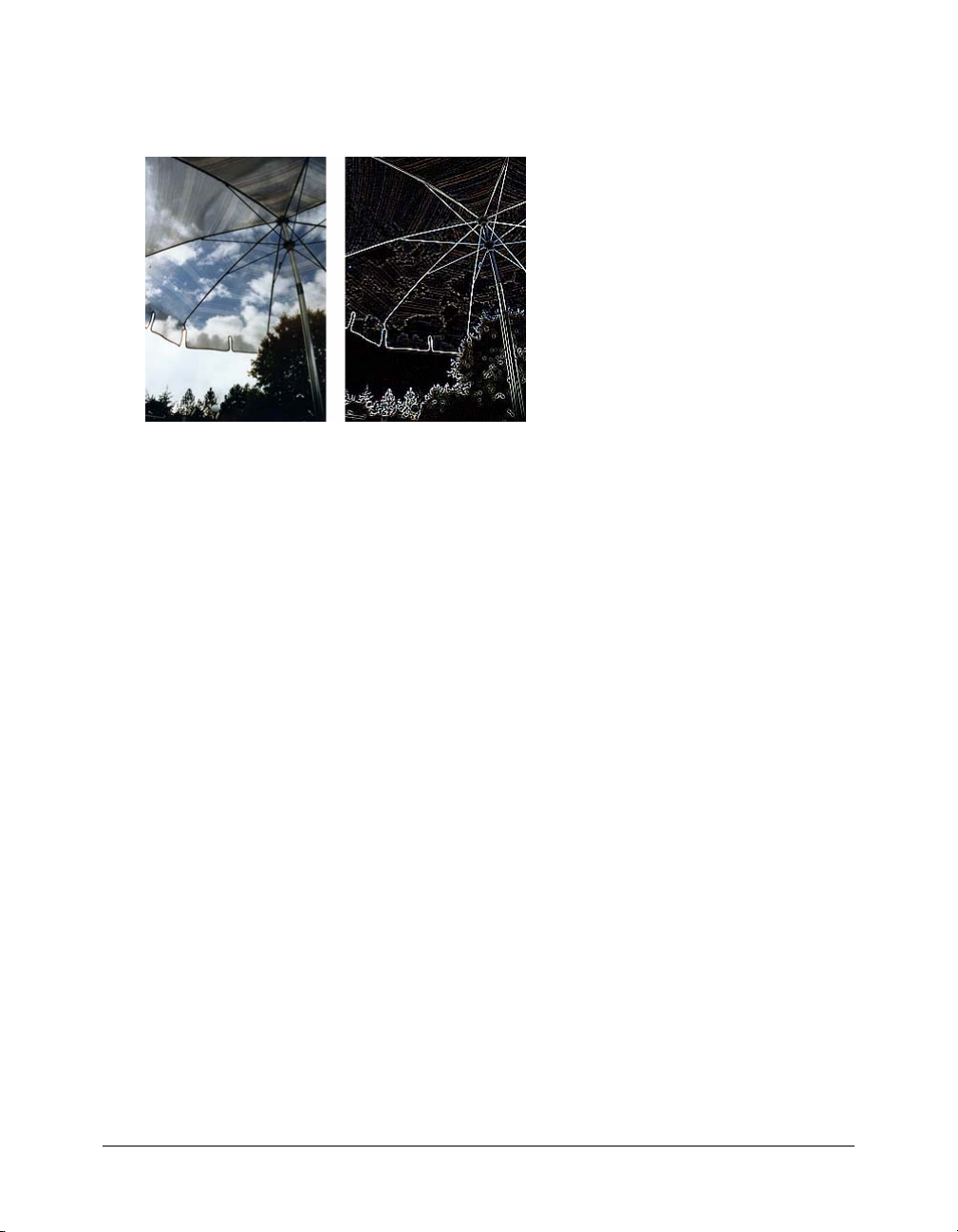
Using the Find Edges effect to create a sketch look
The Find Edges effect changes your bitmaps to look like line drawings by identifying the color
transitions in the images and changing them to lines.
Original; after applying Find Edges
To apply the Find Edges effect to a selected area, do one of the following:
• In the Property inspector, click the Add Effects button, and then choose Other > Find Edges
from the Add Effects pop-up menu.
• Choose Filters > Other > Find Edges.
Note: Applying a filter from the Filters menu is destructive; that is, it cannot be undone except
when Edit > Undo is an option. To maintain the ability to adjust, turn off, or remove this filter, apply it
as a Live Effect, as described in the first bulleted option in this step. For more information, see
“Using Live Effects” on page 119.
Converting an image to a transparency
You can use the Convert to Alpha effect to convert an object or text into a transparency based
upon the transparency of the image.
To apply the Convert to Alpha effect to a selected area, do one of the following:
• In the Property inspector, click the Add Effects button, and then choose Other >
Convert to Alpha from the Add Effects pop-up menu.
• Choose Filters > Other > Convert to Alpha.
Note: Applying a filter from the Filters menu is destructive; that is, it cannot be undone except
when Edit > Undo is an option. To maintain the ability to adjust, turn off, or remove this filter, apply it
as a Live Effect, as described in the first bulleted option in this step. For more information, see
“Using Live Effects” on page 119.
Blurring and sharpening bitmaps 51
Page 52

Using the Sharpen feature to sharpen an image
You can use the Sharpen feature to correct images that are blurry. Fireworks has three Sharpen
options:
Sharpen adjusts the focus of a blurred image by increasing the contrast of adjacent pixels.
Sharpen More increases the contrast of adjacent pixels about three times as much as Sharpen.
Unsharp Mask sharpens an image by adjusting the contrast of the pixel edges. This option offers
the most control, so it is usually the best option for sharpening an image.
Original; after sharpening
To sharpen an image using a sharpen option:
1 Select the image.
2 Do one of the following to choose a sharpen option:
■ In the Property inspector, click the Add Effects button, and then choose Sharpen >
Sharpen or Sharpen More from the Add Effects pop-up menu.
■ Choose Filters > Sharpen > Sharpen or Sharpen More.
Note: Applying a filter from the Filters menu is destructive; that is, it cannot be undone except
when Edit > Undo is an option. To maintain the ability to adjust, turn off, or remove this filter, apply it
as a Live Effect, as described in the first bulleted option in this step. For more information, see
“Using Live Effects” on page 119.
To sharpen an image using Unsharp Mask:
1 Select the image.
2 Do one of the following to open the Unsharp Mask dialog box:
■ In the Property inspector, click the Add Effects button, and then choose Sharpen >
Unsharp Mask from the Add Effects pop-up menu.
■ Choose Filters > Sharpen > Unsharp Mask.
Note: Applying a filter from the Filters menu is destructive; that is, it cannot be undone except
when Edit > Undo is an option. To maintain the ability to adjust, turn off, or remove this filter, apply it
as a Live Effect, as described in the first bulleted option in this step. For more information, see
“Using Live Effects” on page 119.
3 Drag the Sharpen Amount slider to select the amount of sharpening effect from 1% to 500%.
4 Drag the Pixel Radius slider to select a radius from 0.1 to 250.
An increase in radius results in a greater area of sharp contrast surrounding each pixel edge.
52 Chapter 2: Working with Bitmaps
Page 53

5 Drag the Threshold slider to select a threshold of 0 to 255.
Values between 2 and 25 are most commonly used. An increase in threshold sharpens only
those pixels of a higher contrast in the image. A decrease in threshold includes pixels of lower
contrast. A threshold of 0 sharpens all pixels in the image.
6 Click OK.
Adding noise to an image
When viewed at high magnification levels, most images obtained from digital cameras and
scanners do not have perfectly uniform colors. Instead, the colors you see consist of pixels of
many different colors. In image editing, “noise” refers to these random color variations in the
pixels that make up an image.
Sometimes, such as when you are pasting part of one image into another, the difference in the
amount of random color variation in the two images can stand out, preventing the images from
blending together smoothly. In such a case, you can add noise to one or both images to create the
illusion that both images come from the same source. You can also add noise to an image for
artistic reasons, for instance, to simulate an old photograph or static on a television screen.
Original photograph; after adding noise
Adding noise to an image 53
Page 54

To add noise to an image:
1 Select the image.
2 Do one of the following to open the Add Noise dialog box:
■ In the Property inspector, click the Add Effects button, and choose Noise > Add Noise from
the Add Effects pop-up menu.
■ Choose Filters > Noise > Add Noise.
Note: Applying a filter from the Filters menu is destructive; that is, it cannot be undone except
when Edit > Undo is an option. To maintain the ability to adjust, turn off, or remove this filter, apply it
as a Live Effect, as described in the first bulleted option in this step. For more information, see
“Using Live Effects” on page 119.
3 Drag the Amount slider to set the amount of noise.
Values range from 1 to 400. An increase in amount results in an image with more randomly
placed pixels.
4 Select the Color check box to apply color noise. Leave the check box unchecked to apply
monochrome noise only.
5 Click OK.
54 Chapter 2: Working with Bitmaps
Page 55

CHAPTER 3
Working with Vector Objects
A vector object is a computer graphic whose shape is defined by a path. The shape of a vector path
is determined by points that are plotted along the path. A vector object’s stroke color follows the
path. Its fill occupies the area inside the path. The stroke and fill typically determine how the
graphic looks when published in print or on the web.
Macromedia Fireworks MX 2004 has many tools for drawing and editing vector objects using a
variety of techniques. With the basic shape tools, you can quickly draw straight lines, circles and
ellipses, squares and rectangles, stars, and any equilateral polygon with 3 to 360 sides.
You can draw freeform vector paths with the Vector Path and Pen tools. Using the Pen tool, you
can draw complex shapes with smooth curves and straight lines by plotting points one by one.
Fireworks offers several methods for editing the vector objects you have drawn. You can change an
object’s shape by moving, adding, or deleting points. You can use point handles to change the
shape of adjacent path segments. Freeform tools let you alter the shape of objects by editing paths
directly. You can also edit Auto Shapes using their predefined editing methods.
Commands on the Modify menu give you more options for editing objects, including combining
objects to create a single object, creating an object from the intersection of several objects, and
expanding the stroke of an object. You can also import graphics and manipulate them using
these commands.
Drawing vector objects
Fireworks has many tools for drawing vector objects. With these you can draw basic shapes,
freeform paths, and complex shapes by plotting points one by one. You can also draw Auto
Shapes, which are vector object groups that have special controls for adjusting their attributes.
Drawing basic lines, rectangles, and ellipses
You can use the Line, Rectangle, or Ellipse tool to draw basic shapes quickly. The Rectangle tool
draws rectangles as grouped objects. To move a rectangle corner point independently, you must
ungroup the rectangle or use the Subselection tool. To draw a basic rectangle with beveled,
chamfered, or rounded corners, see the following procedure. To draw a Auto Shape rectangle with
rounded corners, see “Adjusting beveled, chamfered, and rounded rectangle Auto Shapes”
on page 59.
55
Page 56

To draw a line, rectangle, or ellipse:
1 Choose the Line, Rectangle, or Ellipse tool.
2 If desired, set the stroke and fill attributes in the Property inspector. See Chapter 5, “Applying
Color, Strokes, and Fills,” on page 97.
3 Drag on the canvas to draw the shape.
For the Line tool, Shift-drag to constrain lines to 45° increments.
For the Rectangle or Ellipse tool, Shift-drag to constrain shapes to squares or circles.
To draw a line, rectangle, or ellipse from a specific center point:
• Position the pointer at the intended center point and Alt-drag (Windows) or Option-drag
(Macintosh) the drawing tool.
To constrain a shape and draw from the center point:
• Position the pointer at the intended center point and Shift-Alt-drag (Windows) or
Shift-Option-drag (Macintosh) the drawing tool.
To adjust the position of a basic shape as you draw it:
• While holding down the mouse button, press and hold the Spacebar, then drag the object to
another location on the canvas. Release the Spacebar to continue drawing the object.
Note: An exception is the Line tool. Pressing the Spacebar while using the Line tool does not
change a line’s position on the canvas.
To resize a selected line, rectangle, or ellipse, do one of the following:
• Enter new width (W) or height (H) values in the Property inspector or the Info panel.
• Choose the Scale tool in the Select section of the Tools panel and drag a corner transform
handle. This resizes the object proportionally.
Note: You can also resize an object proportionally by choosing Modify > Transform > Scale and
dragging a corner transform handle, or by choosing Modify > Transform > Numeric Transform and
entering new dimensions. For more information on resizing and scaling objects, see “Transforming
and distorting selected objects and selections” on page 21.
• Drag a corner point on a rectangle.
Note: Note: Scaling a vector object does not change its stroke width.
Drawing basic rounded rectangles
You can draw rectangles with rounded corners by using the Rounded Rectangle tool, or by using
the Roundness option in the Property inspector to adjust the roundness of the corners of a
selected rectangle. The Rounded Rectangle tool draws rectangles as grouped objects. To
move rounded rectangle points independently, you must ungroup the rectangle or use the
Subselection tool.
To draw a rectangle with rounded corners:
1 Choose the Rounded Rectangle tool, located in the Rectangle tool pop-up menu.
2 Drag the canvas to draw the rectangle.
Tip: You can adjust the roundness of the corners as you draw by pressing any of the arrow keys or
the 1 or 2 number keys repeatedly.
56 Chapter 3: Working with Vector Objects
Page 57

To round the corners of a selected rectangle:
• Enter a value from 0 to 100 in the Roundness box in the Property inspector and press Enter,
or drag the pop-up slider.
Note: If the Property inspector is at half height, click the expander arrow in the lower right corner to
expand it to full height.
Drawing basic polygons and stars
With the Polygon tool, you can draw any equilateral polygon or star, from a triangle to a polygon
or star with 360 sides.
To draw a polygon:
1 Choose the Polygon tool, which is one of the basic shape drawing tools in the Vector section
of the Tools panel.
2 In the Property inspector, do one of the following to specify the number of sides for
the polygon:
■ Use the Sides pop-up slider to choose 3 to 25 sides.
■ Enter a number from 3 to 360 in the Sides text box.
3 Drag to draw the polygon.
To constrain a polygon’s orientation to increments of 45°, hold down Shift as you draw. The
Polygon tool always draws from a center point.
To draw a star:
1 Choose the Polygon tool.
2 In the Property inspector, choose Star from the Shape pop-up menu.
3 In the Sides text box, enter the number of points for the star.
4 Choose Automatic or enter a value in the Angle text box. Values closer to 0 result in long, thin
points; values closer to 100 result in short, stubby points.
5 Drag the canvas to draw the star.
To constrain a star’s orientation to increments of 45°, hold down Shift as you drag. The
Polygon tool always draws from a center point.
Drawing Auto Shapes
Auto Shapes are intelligent vector object groups that adhere to specialized rules to simplify the
creation and editing of common visual elements. Auto Shape tools draw object groups. Unlike
other object groups, selected Auto Shapes have diamond-shaped control points in addition to the
object group handles. Each control point is associated with a particular visual property of the
shape. Dragging a control point alters only the associated visual property. Most Auto Shape
control points have tooltips that describe how they affect the Auto Shape. Move the pointer over
a control point to see a tooltip that describes the property governed by that control point.
Drawing vector objects 57
Page 58

Auto Shape tools create shapes in preset orientations. For example, the Arrow tool draws arrows
horizontally. You can transform Auto Shapes to change their orientation. For more information,
see “Transforming and distorting selected objects and selections” on page 21.
Although each Auto Shape tool in the Tools panel uses the same easy drawing method, the
editable attributes for each Auto Shape are different.
Arrow draws object groups that appear as simple arrows of any proportions. Using control points,
you can adjust the arrowhead flare, the tail length and width, and the tip length.
Bent Arrow draws object groups that appear as right-angled arrows of any proportions. Using
control points, you can adjust the arrowhead flare, the tail length and width, and the tip length.
Beveled Rectangle draws object groups that appear as rectangles with beveled corners. Using
control points, you can edit the amount of bevel for all corners together, or change the bevel of
individual corners.
Chamfer Rectangle draws object groups that appear as rectangles with chamfers, corners that are
rounded to the inside of the rectangle. You can edit the chamfer radius of all corners together, or
change the chamfer radius of individual corners.
Connector Line draws object groups that appear as three-segment connector lines, such as those
used to connect the elements of a flowchart or organizational chart. Using control points, you can
edit the end points for the first and third sections of the connector line, as well as the location of
the second section, which connects the first and last sections.
Doughnut draws object groups that appear as filled rings. Using control points, you can adjust
the inner perimeter or split the shape into pieces.
L-Shape draws object groups that appear as right-angled corner shapes. Using control points,
you can edit the length and width of the horizontal and vertical sections, as well as the curvature
of the corner.
Pie draws object groups that appear as pie charts. Using control points, you can split the shape
into pieces.
Smart Polygon draws object groups that appear as equilateral polygons with 3 to 25 sides.
Using control points, you can resize and rotate, add or remove segments, increase or decrease
the number of sides, or add an inner polygon to the shape.
Rounded Rectangle draws object groups that appear as rectangles with rounded corners. Using
control points, you can edit the roundness of all corners together, or change the roundness of
individual corners.
Spiral draws object groups that appear as open spirals. Using control points, you can edit the
number of spiral rotations, and you can determine whether the spiral is open or closed.
Star draws object groups that appear as stars with any number of points from 3 to 25. Using
control points, you can add or remove points, and adjust the inner and outer angles of the points.
To draw a Auto Shape using the Tools panel:
1 Choose a Auto Shape tool from its pop-up menu in the Vector section of the Tools panel.
2 Do one of the following:
■ Drag the canvas to draw the shape.
■ Click on the canvas to place the shape at its default size.
58 Chapter 3: Working with Vector Objects
Page 59

Adjusting arrow Auto Shapes
Arrows have five control points. There are control points for adjusting the flare of the arrowhead,
the length of the arrow tail, the length of the arrowhead tip, and the width of the arrow tail.
To adjust the flare of an arrowhead:
• Drag the flare control point of a selected arrow.
To increase or decrease the sharpness of an arrowhead:
• Drag the tip control point of a selected arrow.
To lengthen or shorten an arrow tail:
• Drag the body length control point of a selected arrow.
To adjust the width of an arrow tail:
• Drag the body width control point of a selected arrow.
Adjusting bent arrow Auto Shapes
Bent arrows have five control points. There are control points for adjusting the flare of the
arrowhead, the length of the arrowhead tip, the length of the arrow tail, the width of the arrow
tail, and the roundness of the arrow’s bend.
To adjust the flare of the arrowhead of a bent arrow:
• Drag the arrowhead control point of a selected bent arrow.
To increase or decrease the sharpness of the arrowhead of a bent arrow:
• Drag the tip control point of a selected bent arrow.
To lengthen or shorten a bent arrow tail:
• Drag the handle length control point of a selected bent arrow.
To adjust the width of a bent arrow tail:
• Drag the handle width control point of a selected bent arrow.
To adjust the corner roundness of a bent arrow tail:
• Drag the corner radius control point of a selected arrow.
Adjusting beveled, chamfered, and rounded rectangle Auto Shapes
Beveled, chamfered, and rounded rectangles have five control points. The control point on each
corner adjusts all corners together. You can also Alt-drag (Windows) or Option-drag (Macintosh)
to edit a single corner. The remaining control point resizes the rectangle without changing the
roundness of the corner.
Note: To edit the corner radius of rectangles drawn with the Rectangle tool, use the Rectangle
Roundness setting in the Property inspector.
To adjust the corners of a beveled, chamfered, or rounded rectangle Auto Shape:
• Drag a corner control point of a selected shape.
Drawing vector objects 59
Page 60

To adjust a single corner of a beveled, chamfered, or rounded rectangle Auto Shape:
• Alt-drag (Windows) or Option-drag (Macintosh) a corner control point of a selected shape.
To resize a beveled, chamfered, or rounded rectangle Auto Shape without affecting
the corners:
• Drag the drag-to-resize control point.
To convert the corners of a rectangle to a different type:
• Alt-click (Windows) or Option-click (Macintosh) any corner control point.
To convert a single corner to a different type:
• Shift-Alt-click (Windows) or Shift-Option-click (Macintosh) any corner control point.
Adjusting connector line Auto Shapes
Connector lines have five control points. There are control points for placing the start and end
points, for adjusting the position of the cross bar (the line that connects the start and end line
segments), and for adjusting the roundness of the corners.
To move the start or end point of a connector line:
• Drag the control point at the start or end of the connector line.
To reposition the cross bar of a connector line:
• Drag the horizontal position control point.
To adjust all corners of a selected connector line:
• Drag a corner control point.
To adjust a single corner of a selected connector line:
• Alt-drag (Windows) or Option-drag (Macintosh) a corner control point.
Adjusting doughnut Auto Shapes
Doughnut Auto Shapes initially have three control points. There are control points for adjusting
the inner perimeter, for setting the inner perimeter to zero, and for dividing the shape into slices
to resemble a pie chart. You can add as many sections as you want using control points. For each
new section, Fireworks adds a control point for resizing or splitting the new section.
To add sections to a selected doughnut:
• Alt-drag (Windows) or Option-drag (Macintosh) an add/divide sector control point on the
outer perimeter of the shape.
To remove a section from a selected doughnut:
• Drag the add/divide sector control point on the outer perimeter of the shape to define the
portion of the shape that you want to remain on the canvas.
To resize the inner radius of a selected doughnut:
• Drag the inner radius control point.
60 Chapter 3: Working with Vector Objects
Page 61

To set the inner radius of a selected doughnut to zero:
• Click the reset radius control point.
Adjusting pie Auto Shapes
Pie Auto Shapes initially have three control points. There are control points for dividing the shape
into slices, adjusting slice size, and for resetting the pie to one slice. You can add as many sections
as you want using control points. For each new section, Fireworks adds a control point for
resizing or splitting the new section.
To add sections to a selected pie:
• Alt-drag (Windows) or Option-drag (Macintosh) a drag-to-segment control point on the outer
perimeter of the shape.
To resize a slice of a selected pie:
• Drag a drag-to-segment control point on the outer perimeter of the shape.
To reset the a selected pie to one slice:
• Click the Reset control point.
Adjusting L-shaped Auto Shapes
L-shapes have four control points. There are control points for adjusting the length and width of
each section of the L-shape, and for adjusting the roundness of the L-shape’s bend.
To change the length or width of a selected L-shape’s section:
• Drag one of the two length/width control points.
To adjust the roundness of the corners of a selected L-shape:
• Drag the corner radius control point.
Adjusting smart polygon Auto Shapes
Smart Polygons initially appear as pentagons with four control points. There are control points
for resizing and rotating, adding or removing polygon segments, increasing or decreasing the
number of polygon sides, and adding an inner polygon to the shape to create a ring.
To resize or rotate a selected smart polygon, do one of the following:
• Drag the scale/rotate control point.
• Alt-drag (Windows) or Option-drag (Macintosh) the scale/rotate control point to rotate only.
To add or remove sections from a selected smart polygon:
• Drag the sections control point.
To change the number of sides on a selected smart polygon:
• Drag the sides control point.
To split a selected smart polygon into segments.
• Alt-drag (Windows) or Option-drag (Macintosh) the sides control point.
Drawing vector objects 61
Page 62

To resize the inner polygon of a smart polygon, do one of the following:
• If the polygon has an inner polygon, drag the inner polygon control point.
• If the polygon has no inner polygon, drag the reset inner polygon control point.
To reset the inner polygon of a selected smart polygon:
• Click the reset inner polygon control point.
Adjusting spiral Auto Shapes
Spirals have two control points. There are control points for adjusting the number of turns in the
spiral, and for making the spiral open or closed.
To adjust the number of turns in a selected spiral:
• Drag the spirals control point.
To open or close a selected spiral:
• Click the open/close spiral control point.
Adjusting star Auto Shapes
Stars initially have five control points. There are control points for adding or removing points, for
adjusting the inner and outer angles of the points, and for adjusting the roundness of the peaks
and valleys.
To change the number of sides on a selected star:
• Drag the Points control point.
To adjust the valleys of a selected star:
• Drag the valley control point.
To adjust the points of a selected star:
• Drag the peak control point.
To adjust the roundness of a selected star’s peaks or valleys:
• Drag a Roundness control point.
Using the Assets panel to add Auto Shapes to a drawing
The Assets panel contains a Shapes tab where you can find additional Auto Shapes. These Auto
Shapes are generally more complex than those that appear in the Tools panel. Instead of drawing
these Auto Shapes directly on the canvas, you place these Auto Shapes into your drawing by
dragging them from the Assets panel to the canvas.
To create a Auto Shape using the Assets panel:
1 Choose Window > Auto Shapes to display the Shapes tab, if it is not already visible.
2 Drag a Auto Shape preview from the Assets panel to the canvas.
3 If desired, edit the Auto Shape by dragging any of its control points.
62 Chapter 3: Working with Vector Objects
Page 63

Adding new Auto Shapes to Fireworks
You can add new Auto Shapes to Fireworks using the Fireworks Exchange website. Some new
Auto Shapes will appear in the Shapes tab in the Assets panel, and others will appear in the Tools
menu, grouped with the other Auto Shapes.
You can also add new Auto Shapes to Fireworks by writing the JavaScript code for the Auto
Shapes yourself. For more information, see Extending Fireworks.
To add new Auto Shapes to Fireworks:
1 Choose Window > Auto Shapes to display the Shapes tab, if it is not already visible.
2 Choose Get More Auto Shapes from the Auto Shapes panel Options menu.
Fireworks connects to the web and navigates to the Fireworks Exchange website.
3 Follow the onscreen instructions to select new Auto Shapes and add them to Fireworks.
Drawing freeform paths
You can draw freeform vector paths with the Vector Path tool, much as you draw using a felt-tip
marker or crayon. The Vector Path tool is located in the Pen tool pop-up menu.
You can change the stroke and fill attributes of paths drawn with the Vector Path tool.
See Chapter 5, “Applying Color, Strokes, and Fills,” on page 97.
Using the Vector Path tool
The Vector Path tool has a wide variety of brush stroke categories, including Air Brush,
Calligraphy, Charcoal, Crayon, and Unnatural. Each category typically has a choice of strokes,
such as Light Marker and Dark Marker, Splattered Oil, Bamboo, Ribbon, Confetti, 3D,
Toothpaste, and Viscous Alien Paint.
Although the strokes may look like paint or ink, each has the points and paths of a vector object.
That means that you can change the shape of the stroke using any of several vector-editing
techniques. After you reshape the path, the stroke is redrawn.
A painting edited by moving vector points
Drawing vector objects 63
Page 64

You can also modify existing brush strokes and add fills to selected objects you have drawn with
the Vector Path tool. The new stroke and fill settings are retained for subsequent use of the Vector
Path tool in the current document.
To draw a freeform vector path:
1 Choose the Vector Path tool, located in the Pen tool pop-up menu.
2 If desired, set stroke and fill attributes in the Property inspector. See Chapter 5, “Applying
Color, Strokes, and Fills,” on page 97.
3 Drag to draw. To constrain the path to a horizontal or vertical line, hold down Shift while
dragging.
4 Release the mouse button to end the path. To close the path, release the mouse button when
you return the pointer to the point at the beginning of the path.
Drawing paths by plotting points
One way to draw and edit vector objects in Fireworks is to plot points as if drawing a
connect-the-dots picture. When you click each point with the Pen tool, Fireworks automatically
draws the path of the vector object from the last point you clicked.
In addition to connecting the points with only straight segments, the Pen tool can draw smooth,
mathematically derived curve segments known as Bézier curves. Each point’s type—corner point
or curve point—determines whether the adjacent curves are straight lines or curves.
You can modify straight and curved path segments by dragging their points. You can further
modify curved path segments by dragging their point handles. You can also convert straight path
segments to curved (and vice versa) by converting their points.
Drawing straight path segments
Drawing straight line segments with the Pen tool is a simple matter of clicking to place the points.
Each click with the Pen tool plots a corner point.
64 Chapter 3: Working with Vector Objects
Page 65

To draw a path with straight line segments:
1 Choose the Pen tool.
2 If desired, choose Edit > Preferences and enable any of the following options on the Editing tab
of the Preferences dialog box, then click OK:
Show Pen Preview previews the line segment that would result from the next click.
Show Solid Points shows solid points while you draw.
Note: On Mac OS X, choose Fireworks > Preferences to open the Preferences dialog box.
3 Click on the canvas to place the first corner point.
4 Move the pointer and click to place the next point. A straight line segment joins the two points.
5 Continue plotting points. Straight segments bridge each gap between points.
6 Do one of the following to end the path, either open or closed:
■ Double-click the last point to end the path as an open path.
■ Choose another tool to end the path as an open path.
Note: When you choose any selection tool or vector tool other than the Text tool and then return
to the Pen tool, Fireworks resumes drawing the object at your next click.
■ To close the path, click the first point you plotted. The beginning and end points of a closed
path are the same.
Note: Loops formed by a path overlapping itself are not closed paths. Only paths that begin and
end on the same point are closed paths.
Drawing curved path segments
To draw curved path segments, you click and drag as you plot points. As you draw, the current
point shows point handles. Whether drawn with the Pen tool or with another Fireworks drawing
tool, all points on all vector objects have point handles. These handles are visible only on curve
points, however.
Drawing vector objects 65
Page 66

To draw an object with curved segments:
1 Choose the Pen tool.
2 Click to place the first corner point.
3 Move to the location of the next point, then click and drag to produce a curve point. Each time
you click and drag, Fireworks extends the line segment to the new point.
4 Continue plotting points. If you click and drag a new point, you produce a curve point; if you
just click, you produce a corner point.
Tip: You can temporarily switch to the Subselection tool to change the location of points and the
shape of curves as you draw. Press Control (Windows) or Command (Macintosh) while dragging a
point or point handle with the Pen tool.
5 Do one of the following to end the path, either open or closed:
■ Double-click the last point to end the path as an open path.
■ Choose another tool to end the path as an open path. When you choose certain tools and
then return to the Pen tool, Fireworks resumes drawing the object at your next click.
■ To close a path, click the first point you plotted. The beginning and end points of a closed
path are the same.
Adjusting the shape of a straight path segment
You can lengthen, shorten, or change the position of a straight path segment by moving its points.
To change a straight path segment:
1 Select the path with the Pointer or Subselection tool.
2 Click a point with the Subselection tool to select it.
Selected corner points appear as solid blue squares.
3 Drag the point or use the arrow keys to move the point to a new location.
66 Chapter 3: Working with Vector Objects
Page 67
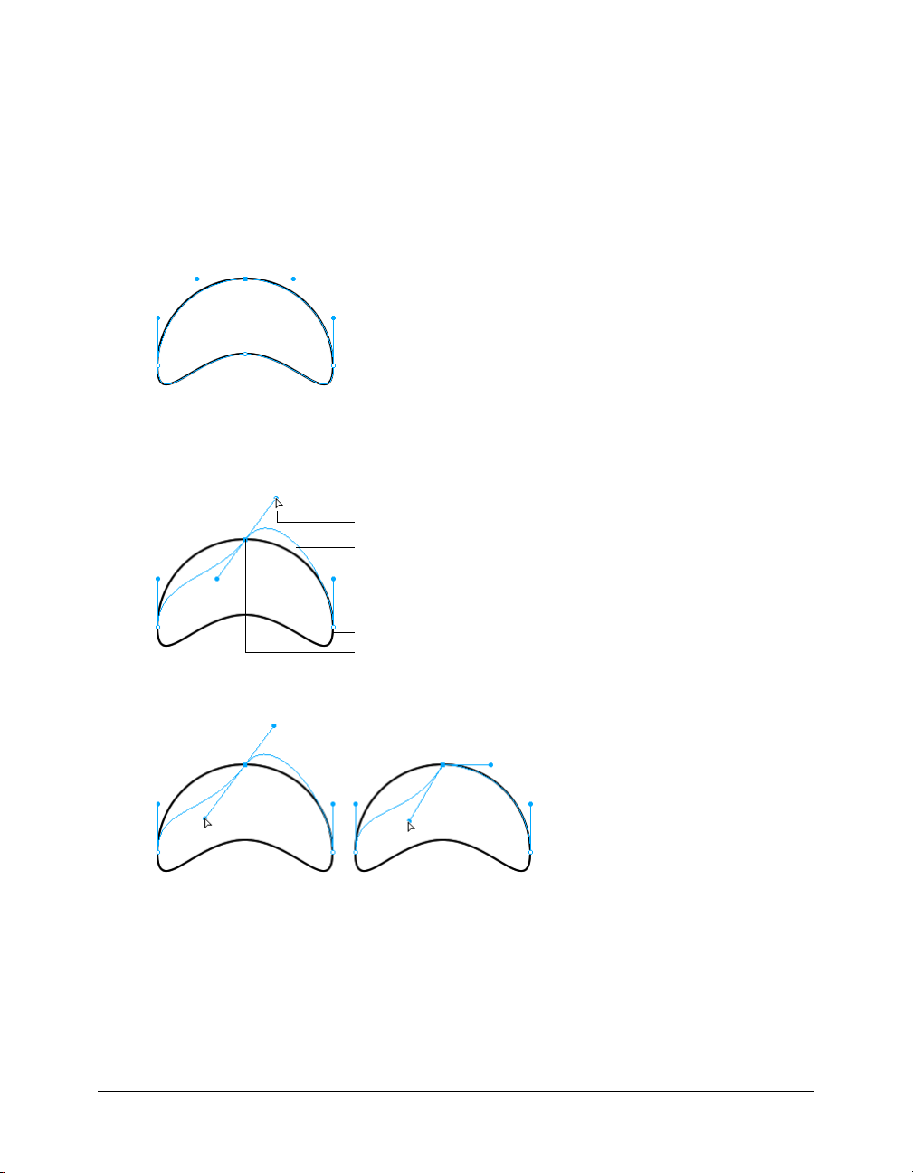
Adjusting the shape of a curved path segment
You can change the shape of a vector object by dragging its point handles with the Subselection
tool. The point handles determine the degree of curvature between fixed points. These curves are
known as Bézier curves.
To edit the Bézier curve of a path segment:
1 Select the path with the Pointer or Subselection tool.
2 Click a curve point with the Subselection tool to select it.
A selected curve point appears as a solid blue square. The point handles extend from the point.
3 Drag the handles to a new location. To constrain handle movement to 45° angles, press Shift
while dragging.
The blue path preview shows where the new path will be drawn if you release the
mouse button.
Point handles
Subselection pointer
Path preview
Path
Selected point
For example, if you drag the left point handle downward, the right point handle goes up.
Alt-drag a handle to move it independently
Drawing vector objects 67
Page 68
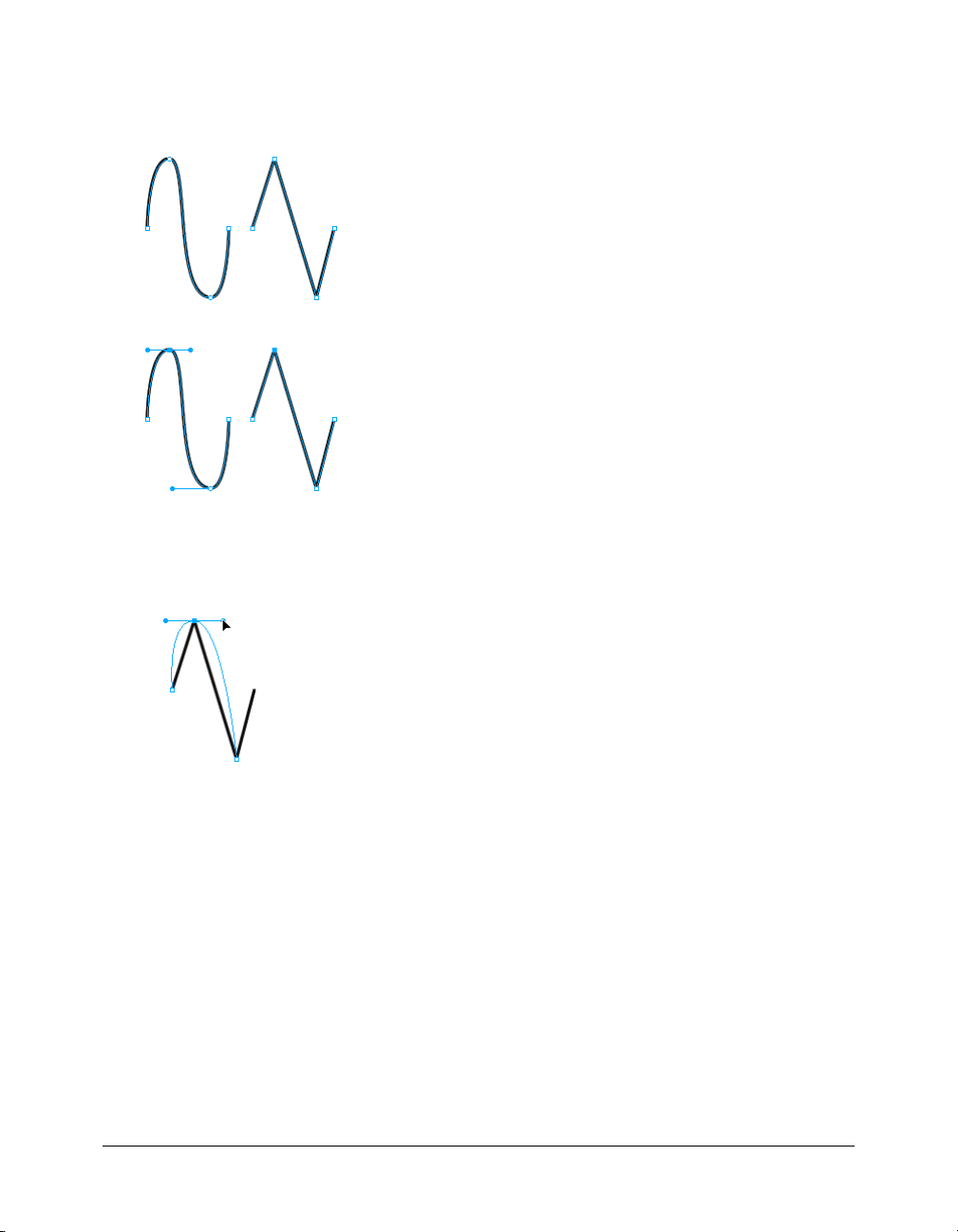
Converting path segments to straight or curved
Straight path segments are intersected by corner points. Curved path segments contain
curve points.
You can convert a straight segment to a curved segment and vice versa by converting its point.
To convert a corner point to a curve point:
1 Choose the Pen tool.
2 Click a corner point on a selected path and drag away from it.
The handles extend, curving the adjacent segments.
Note: To edit the point’s handles, choose the Subselection tool or press Control (Windows) or
Command (Mac) while the Pen tool is active.
68 Chapter 3: Working with Vector Objects
Page 69
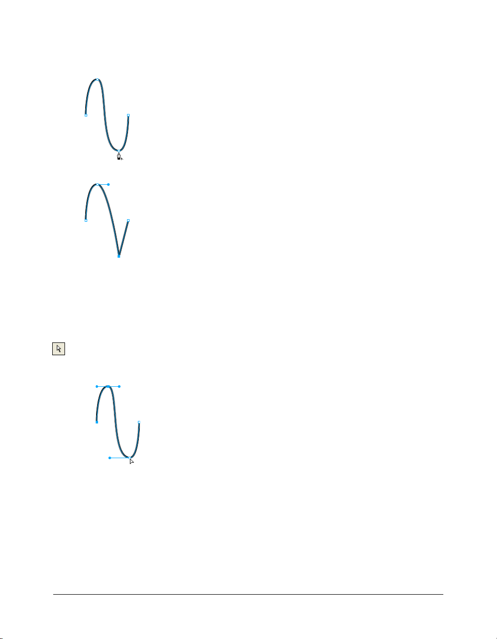
To convert a curve point to a corner point:
1 Choose the Pen tool.
2 Click a curve point on a selected path.
The handles retract, and the adjacent segments straighten.
Selecting points
The Subselection tool allows you to select multiple points. Before selecting a point with the
Subselection tool, you must select the path using the Pointer or Subselection tool or by clicking its
thumbnail in the Layers panel.
To select specific points on a selected path:
1 Choose the Subselection tool.
2 Do one of the following:
■ Click a point, or hold down Shift and click multiple points one by one.
■ Drag around the points to be selected.
To display a curve point’s handles:
• Click the point with the Subselection tool. If either point nearest the clicked point is a curve
point, the near handle is also displayed.
Drawing vector objects 69
Page 70
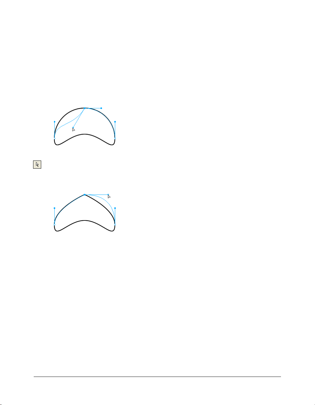
Moving points and point handles
You can change an object’s shape by dragging its points and point handles with the
Subselection tool.
To move a point:
• Drag it with the Subselection tool.
Fireworks redraws the path to reflect the point’s new position.
To change the shape of a path segment:
• Drag a point handle with the Subselection tool. Alt-drag (Windows) or Option-drag
(Macintosh) to drag one handle at a time.
To adjust the handle of a corner point:
1 Choose the Subselection tool.
2 Select a corner point.
3 Alt-drag (Windows) or Option-drag (Macintosh) the point to display its handle and bend the
adjacent segment.
Dragging a corner point handle with the Subselection tool to edit the adjacent path segment
Inserting and deleting points on a path
You can add points to a path and delete points from a path. Adding points to a path gives you
control over a specific segment within the path. Deleting points from the path reshapes it or
simplifies editing.
To insert a point on a selected path:
• Using the Pen tool, click anywhere on the path where there is not a point.
To delete a point from a selected path segment, do one of the following:
• Click a corner point on a selected object with the Pen tool.
• Double-click a curve point on a selected object with the Pen tool.
• Select a point with the Subselection tool and press Delete or Backspace.
70 Chapter 3: Working with Vector Objects
Page 71

Continuing an existing path
You can use the Pen tool to continue drawing an existing open path.
To resume drawing an existing open path:
1 Choose the Pen tool.
2 Click the end point and continue the path.
The Pen tool pointer changes to indicate that you are adding to a path.
Merging two open paths
You can connect two open paths to form one continuous path. When you connect two paths, the
topmost path’s stroke, fill, and effect attributes become the attributes of the newly merged path.
To merge two open paths:
1 Choose the Pen tool.
2 Click the end point of one of the paths.
3 Move the pointer to the end point of the other path and click.
Auto-joining similar open paths
You can easily join one open path with another that has similar stroke and fill characteristics.
To auto-join two open paths:
1 Select an open path.
2 Choose the Subselection tool and drag an end point of the path within a few pixels of the end
point of the similar path.
The end point snaps to the other path, and the two become a single path.
Editing paths
Fireworks offers several methods for editing vector objects. You can change an object’s shape by
moving, adding, or deleting points, or you can move point handles to change the shape of
adjacent path segments. Freeform tools let you alter the shape of objects by editing paths directly.
You can also use path operations to create new shapes by combining or altering existing paths.
Editing with vector tools
In addition to dragging points and point handles, you can use several Fireworks tools to edit
vector objects directly.
Editing paths 71
Page 72
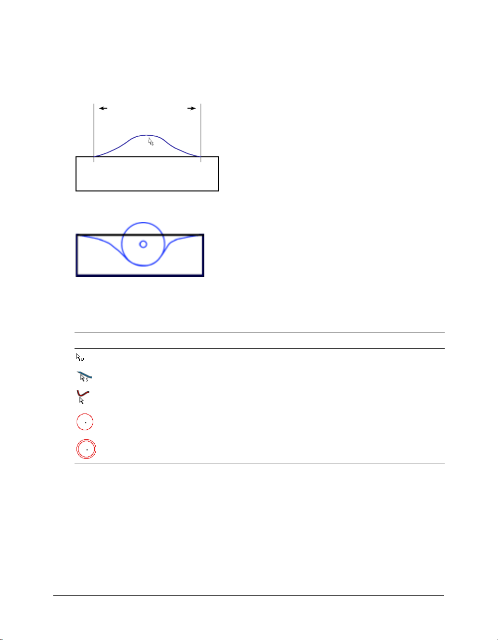
Bending and reshaping vector objects
The Freeform tool allows you to bend and reshape vector objects directly instead of manipulating
points. You can push or pull any part of a path, regardless of where the points are located.
Fireworks automatically adds, moves, or deletes points along the path as you change the vector
object’s shape.
Specified length
Freeform tool pulling a path segment
Freeform tool pushing a path segment
As you move the pointer over a selected path, it changes to the push or pull pointer, depending on
its location relative to the selected path.
Pointer Meaning
The Freeform tool is in use.
The Freeform tool is in use, and the pull pointer is in position to pull the selected path.
The Freeform tool is in use, and the pull pointer is pulling the selected path.
The Freeform tool is in use, and the push pointer is active.
The Reshape Area tool is in use, and the reshape area pointer is active. The area from
the inner circle to the outer circle represents reduced strength.
When the pointer is directly over the path, you can pull the path. When the pointer is not directly
over the path, you can push the path. You can change the size of the push or pull pointer.
Note: The Freeform tool also responds to pressure from a Wacom or other compatible tablet.
72 Chapter 3: Working with Vector Objects
Page 73
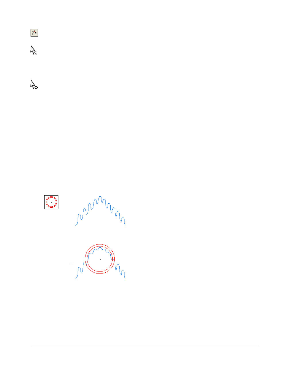
To pull a selected path:
1 Choose the Freeform tool.
2 Move the pointer directly over the selected path.
The pointer changes to the pull pointer.
3 Drag the path.
To push a selected path:
1 Choose the Freeform tool.
The pointer changes to the push or pull pointer.
2 Point slightly away from the path.
3 Drag toward the path to push it. Nudge the selected path to reshape it.
To change the size of the push pointer, do one of the following:
• While holding down the mouse button, press the Right Arrow key or 2 to increase the width of
the pointer.
• While holding down the mouse button, press the Left Arrow key or 1 to decrease the width of
the pointer.
• To set the size of the pointer and set the length of the path segment that it affects, deselect all
objects in the document, and then enter a value from 1 to 500 in the Size text box of the
Property inspector. The value indicates the size of the pointer in pixels.
Distorting paths
You can use the Reshape Area tool to pull the area of all selected paths within the outer circle of
the reshape area pointer.
The pointer’s inner circle is the boundary of the tool at full strength. The area between the inner
and outer circle reshapes paths at less than full strength. The pointer’s outer circle determines the
gravitational pull of the pointer. You can set its strength.
Note: The Reshape Area tool also responds to pressure from a Wacom or other compatible tablet.
Editing paths 73
Page 74

To distort selected paths:
1 Choose the Reshape Area tool, located in the Freeform tool pop-up menu.
2 Drag across the paths to redraw them.
To change the size of the reshape area pointer, do one of the following:
• While holding down the mouse button, press the Right Arrow key or 2 to increase the width of
the pointer.
• While holding down the mouse button, press the Left Arrow key or 1 to decrease the width of
the pointer.
• To set the size of the pointer and set the length of the path segment that it affects, deselect all
objects in the document, and then enter a value from 1 to 500 in the Size text box of the
Property inspector. The value indicates the size of the pointer in pixels.
To set the strength of the inner circle of the reshape area pointer:
• Enter a value from 1 to 100 in the Strength text box of the Property inspector. The value
indicates the percentage of the pointer’s potential strength. The higher the percentage, the
greater the strength.
Redrawing paths
You can use the Redraw Path tool to redraw or extend a segment of a selected path while retaining
the path’s stroke, fill, and effect characteristics.
To redraw or extend a segment of a selected path:
1 Choose the Redraw Path tool, located in the Pen tool pop-up menu.
2 Move the pointer directly over the path.
The pointer changes to the redraw path pointer.
3 Drag to redraw or extend a path segment. The portion of the path to be redrawn is
highlighted in red.
4 Release the mouse button.
Changing a path’s appearance by varying pressure and speed
You can change the appearance of a path using the Path Scrubber tools. Using varying pressure or
speed, you can change a path’s stroke properties. These properties include stroke size, angle, ink
amount, scatter, hue, lightness, and saturation. You can specify which of these properties is
affected by the Path Scrubber tools using the Sensitivity tab of the Edit Stroke dialog box. You can
also specify how much pressure and speed affects these properties. For details on setting options in
the Edit Stroke dialog box, see “Working with strokes” on page 106.
74 Chapter 3: Working with Vector Objects
Page 75

Cutting paths into multiple objects
The Knife tool allows you to slice a path into two or more paths.
To cut a selected path:
1 Choose the Knife tool.
Note: Using the eraser on Wacom pens automatically selects the Knife tool.
2 Do one of the following:
■ Drag the pointer across the path.
■ Click on the path.
3 Deselect the path.
Editing with path operations
You can use path operations in the Modify menu to create new shapes by combining or altering
existing paths. For some path operations, the stacking order of selected path objects defines how
the operation works. For information on arranging the stacking order of selected objects, see
“Stacking objects” on page 26.
Note: Using a path operation removes all pressure and speed information from the affected paths.
Combining path objects
You can combine path objects into a single path object. You can connect the end points of
two open paths to create a single closed path, or you can join multiple paths to create a
composite path.
To create one continuous path from two open paths:
1 Choose the Subselection tool.
2 Select two end points on two open paths.
3 Choose Modify > Combine Paths > Join.
To create a composite path:
1 Select two or more open or closed paths.
2 Choose Modify > Combine Paths > Join.
To break apart a composite path:
1 Select the composite path.
2 Choose Modify > Combine Paths > Split.
Editing paths 75
Page 76

To combine selected closed paths as one path enclosing the entire area of the
original paths:
• Choose Modify > Combine Paths > Union. The resulting path assumes the stroke and fill
attributes of the object that is placed farthest back.
Creating an object from the intersection of other objects
Using the Intersect command, you can create an object from the intersection of two or more
objects.
To create a closed path that encloses the area common to all selected closed paths:
• Choose Modify > Combine Paths > Intersect. The resulting path assumes the stroke and fill
attributes of the object that is placed farthest back.
Removing portions of a path object
You can remove portions of a selected path object as defined by the overlapping portions of
another selected path object arranged in front of it.
To remove portions of a path object:
1 Select the path object that defines the area to be removed.
2 Choose Modify > Arrange > Bring to Front.
3 Hold down Shift and add to the selection the path object from which the portions are to
be removed.
4 Choose Modify > Combine Paths > Punch.
Stroke and fill attributes remain unchanged.
76 Chapter 3: Working with Vector Objects
Page 77

Cropping a path
You can crop a path using the shape of another path. The front or topmost path defines the shape
of the cropped area.
To crop a selected path:
1 Select the path object that defines the area to be cropped.
2 Choose Modify > Arrange > Bring to Front.
3 Hold down Shift and add to the selection the path object to be cropped.
4 Choose Modify > Combine Paths > Crop.
The resulting path object retains the stroke and fill attributes of the object that is placed
farthest back.
Simplifying a path
You can remove points from a path while maintaining its overall shape. The Simplify command
removes redundant points on your path by an amount you specify.
You might want to use Simplify if you have a straight line that contains more than two points,
for example. (Only two points are necessary to produce a straight line.) Or perhaps your path
contains points that lie exactly on top of one another. Simplify removes points that are
unnecessary to reproduce the path you’ve drawn.
To simplify a selected path:
1 Choose Modify > Alter Path > Simplify.
The Simplify dialog box appears.
2 Enter a simplification amount and click OK.
As you increase the amount of simplification, you increase the degree to which Fireworks can
alter the path to reduce the number of points on that path.
Editing paths 77
Page 78

Expanding a stroke
You can convert the stroke of a selected path into a closed path. The resulting path creates the
illusion of a path with no fill and a stroke that takes on the same attributes as the original
object’s fill.
Note: Expanding the stroke of a path that intersects itself can produce interesting results. If the
original path contains a fill, the intersecting portions of the path will not contain a fill after the stroke
is expanded.
To expand a selected object’s stroke:
1 Choose Modify > Alter Path > Expand Stroke to open the Expand Stroke dialog box.
2 Set the width of the resulting closed path.
3 Specify a corner type: miter, round, or beveled.
4 If you chose miter, set the miter limit, the point at which a miter corner automatically becomes
a beveled corner. The miter limit is the ratio of miter corner length to stroke width.
5 Choose an end cap option: butt, square, or round. Then click OK.
A closed path in the shape of the original and with the same stroke and fill attributes replaces
the original path.
Contracting or expanding a path
You can contract or expand the path of a selected object by a specific number of pixels.
To expand or contract a selected path:
1 Choose Modify > Alter Path > Inset Path to open the Inset Path dialog box.
2 Choose a direction to contract or expand the path:
Inside contracts the path.
Outside expands the path.
3 Set the width between the original path and the contracting or expanding path.
4 Specify a corner type: miter, round, or beveled.
5 If you chose miter, set the miter limit, the point at which a miter corner automatically becomes
a beveled corner. The miter limit is the ratio of miter corner length to stroke width.
6 Click OK.
A smaller or larger path object with the same stroke and fill attributes replaces the original
path object.
78 Chapter 3: Working with Vector Objects
Page 79

CHAPTER 4
Using Text
Macromedia Fireworks MX 2004 has many text features typically reserved for sophisticated
desktop publishing applications. You can create text in a variety of fonts and sizes and adjust
kerning, spacing, color, leading, baseline shift, and more. Combining Fireworks text-editing
features with the wide range of strokes, fills, effects, and styles makes text a lively element of your
graphic designs. You can also use the Fireworks spell-checker to correct misspellings.
The capability to edit text anytime—even after you apply Live Effects such as drop shadows and
bevels—means you can easily make changes to text. You can also copy objects that include text
and change the text for each copy. Vertical text, transformed text, text attached to paths, and text
converted to paths and images extend the design possibilities.
You can import text while retaining rich text format attributes. Also, when you import a
Photoshop document containing text, the text remains editable. Fireworks handles missing
fonts upon import by asking you to choose a substitute font or allowing you to import text as
a static image.
Entering text
You can enter, format, and edit text in your graphics using the Text tool and the options in the
Property inspector.
Te x t t o ol
Note: If the Property inspector is minimized, click the expander arrow in the lower right corner to see
all text properties.
The Property inspector when the Text tool is selected
79
Page 80

Creating text blocks
All text in a Fireworks document appears inside a rectangle with handles called a text block.
To enter text:
1 Choose the Text tool.
The Property inspector displays options for the Text tool.
2 Choose color, font, size, spacing, and other text characteristics.
3 Do one of the following:
■ Click in your document where you want the text block to begin. This creates an auto-sizing
text block.
■ Drag to draw a text block. This creates a fixed-width text block.
For information on the different types of text blocks, see “Using auto-sizing and fixed-width
text blocks” on page 81.
4 Type your text. To enter a paragraph break, press Enter.
5 If desired, highlight text within the text block after you type it and reformat it.
6 When you have finished entering text, do one of the following:
■ Click outside the text block.
■ Choose another tool in the Tools panel.
■ Press Escape.
Moving text blocks
You can select a text block and move it anywhere in your document, as you would any other
object. You can also move text blocks as you drag to create them.
To move a text block:
• Drag it to the new location.
To move a text block while you drag to create it:
1 While holding down the mouse button, press and hold down the Spacebar, then drag the text
block to another location on the canvas.
2 Release the Spacebar to continue drawing the text block.
80 Chapter 4: Using Text
Page 81

Using auto-sizing and fixed-width text blocks
Fireworks has both auto-sizing text blocks and fixed-width text blocks. An auto-sizing text block
expands horizontally as you type. If you remove text, the auto-sizing text block shrinks to
accommodate only the remaining text. Auto-sizing text blocks are created by default when you
click on the canvas with the Text tool and start typing.
Fixed-width text blocks allow you to control the width of wrapped text. Fixed-width text blocks
are created by default when you drag to draw a text block using the Text tool.
When the text pointer is active within a text block, a hollow circle or hollow square appears in the
upper right corner of the text block. The circle indicates an auto-sizing text block; the square
indicates a fixed-width text block. Double-click the corner to change from one kind of text block
to the other.
Fixed-width indicator
Auto-sizing indicator
A fixed-width text block and an auto-sizing text block
To change a text block to fixed-width or auto-sizing:
1 Double-click inside the text block.
2 Double-click the circle or square in the upper right corner of the text block.
The text block changes to the other type.
To change a selected text block to fixed-width by resizing it:
• Drag a resize handle.
This automatically changes the text block from auto-sizing to fixed-width.
Editing text
Within a text block, you can vary all aspects of text, including size, font, spacing, leading,
and baseline shift. When you edit text, Fireworks redraws its stroke, fill, and effect
attributes accordingly.
You can change a text block’s attributes using the Property inspector. If the Property inspector is
minimized, click the expander arrow in the lower right corner to see all text properties.
Property inspector when a text block is selected
Editing text 81
Page 82
You can also use the Text Editor and the commands in the Text menu to edit text, but the
Property inspector offers the quickest way to change text attributes and provides more detailed
editing control than the other two options. For more information about the Text Editor, see
“Using the Text Editor” on page 95.
Note: Changes you make during a text-editing session constitute only one Undo. Choosing Edit >
Undo while editing text will undo every text edit you’ve made from the time you double-clicked the
text block to edit its contents.
To edit text:
1 Select the text you want to change:
■ Click a text block with the Pointer or Subselection tool to select the entire block. To select
multiple blocks simultaneously, hold down Shift as you select each block.
■ Double-click a text block with the Pointer or Subselection tool, and highlight a range
of text.
■ Click inside a text block with the Text tool, and highlight a range of text.
2 Make your changes.
For information about changing text attributes, see “Choosing a font, size, and text style”
on page 82, “Applying text color” on page 82, “Setting kerning” on page 84, “Setting leading”
on page 85, “Setting text orientation” on page 85, “Setting text alignment” on page 86, and
“Indenting text” on page 87.
3 Do one of the following to apply your changes:
■ Click outside the text block.
■ Choose another tool in the Tools panel.
■ Press Escape.
Choosing a font, size, and text style
You use the Property inspector to change the font, size, and style attributes of the text in a
text block.
To change the font, size, and style of selected text using the Property inspector:
1 To change the font, choose a font from the Font pop-up menu.
2 To change the font size, drag the Font Size pop-up slider or enter a value in the text box. Font
size is measured in points.
3 To apply a bold, italic, or underline style, click the corresponding style button.
Applying text color
Text color is controlled by the Fill Color box. By default, text is black and has no stroke. You can
change the color of all text in a selected text block or of highlighted text in a text block. The Text
tool retains the current text color from text block to text block.
82 Chapter 4: Using Text
Page 83
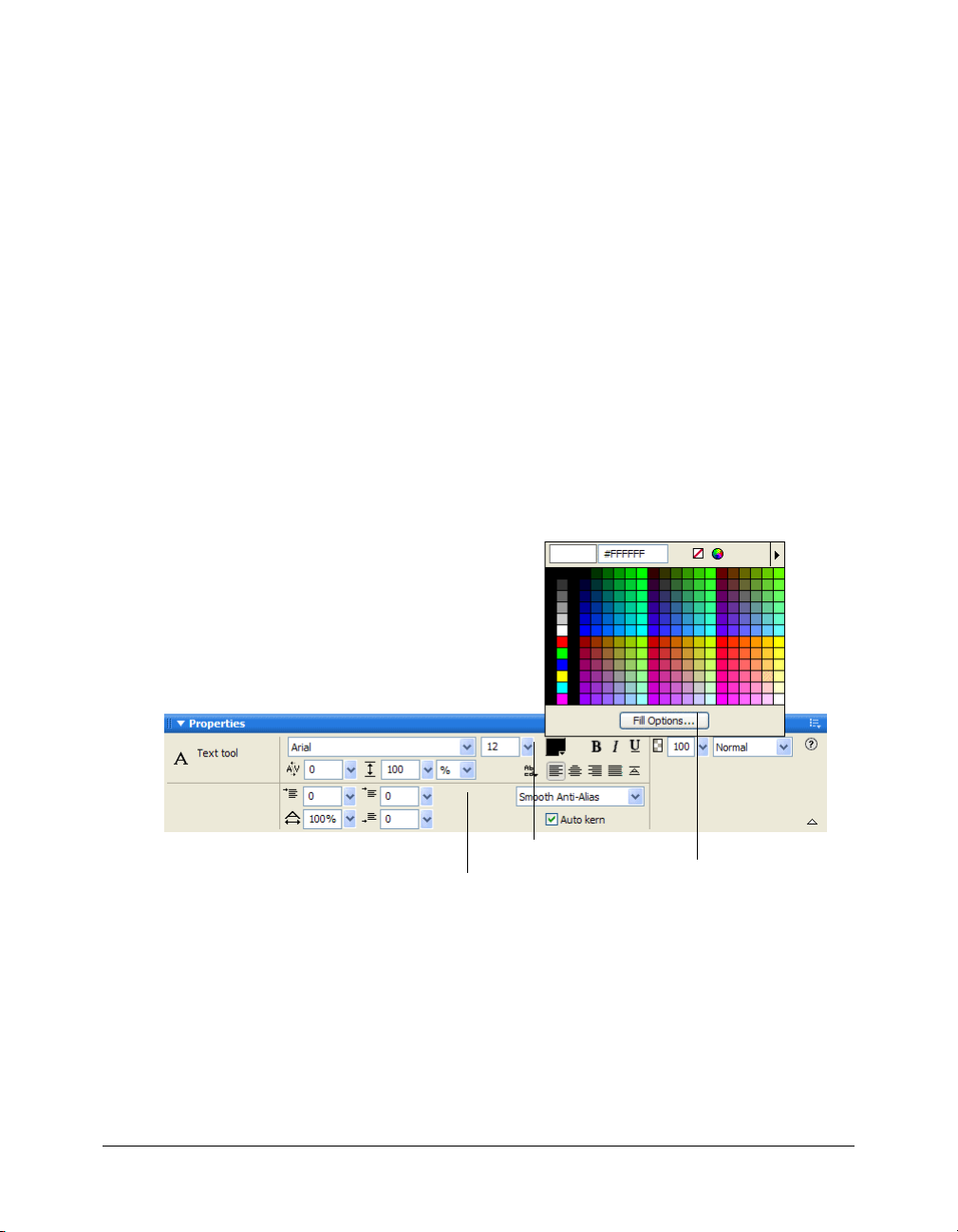
The Text tool retains the current text color independently of the fill color of other tools. When
you use another tool after using the Text tool, the fill and stroke settings revert to the most recent
settings from before the Text tool was used. Likewise, when you return to the Text tool, the fill
color reverts to the most recent Text tool setting, and the stroke is reset to None. Fireworks
retains the current Text tool color as you switch from document to document or close and
reopen Fireworks.
You can add a stroke and Live Effects to all text in a selected text block, but not to highlighted
text in a text block. Fireworks updates stroke characteristics and Live Effects applied to a text
block as you edit text in the text block, but the Text tool does not retain stroke characteristics or
Live Effects if you create a new text block. For more information, see “Applying strokes, fills, and
effects to text” on page 89.
Applying color to all text in selected text blocks
You can apply text color to all text in selected text blocks using the Property inspector, any Fill
Color box, or the Eyedropper tool. You can also use any of these methods to set the text color for
the Text tool.
To set the color of all text in a selected text block, do one of the following:
• Click the Fill Color box in the Property inspector and choose a color from the color pop-up
window, or sample a color from anywhere on the screen using the eyedropper pointer while
either color pop-up window is open.
Fill Color box
Stroke Color box
Fill Color pop-up
window
Fill Color box in the Property inspector
• Click the Fill Color box in the Tools panel and choose a color from the color pop-up window,
or sample a color from anywhere on the screen using the eyedropper pointer while the Fill
Color box pop-up window is open.
• Click the icon next to the Fill Color box in the Tools panel, choose the Eyedropper tool, and
then click to sample a color anywhere in any open document.
Editing text 83
Page 84

The color of the Fill Color box in the Tools panel changes to reflect the color you sample
with either the eyedropper pointer or the Eyedropper tool, and the color of the selected text
also changes.
Applying color to highlighted text in a text block
You can change the text color of highlighted text in a text block using the Property inspector or
any Fill Color box. You cannot use the Eyedropper tool to edit the color of highlighted text.
Note: If you attempt to apply a stroke or Live Effect to highlighted text in a text block, the entire text
block is automatically selected.
To apply text color only to highlighted text in a text block, do one of the following:
• Click the Fill Color box in the Property inspector and choose a color from the color pop-up
window, or sample a color from anywhere on the screen using the eyedropper pointer while the
Fill Color box pop-up window is open.
• Click the Fill Color box in the Tools panel and choose a color from the color pop-up window,
or sample a color from anywhere on the screen using the eyedropper pointer while the Fill
Color box pop-up window is open.
Setting kerning
Kerning increases or decreases the spacing between certain pairs of letters to improve their
appearance. Most fonts include information that automatically reduces the amount of space
between certain letter pairs, such as “TA” or “Va.” Fireworks auto-kerning uses a font’s kerning
information when displaying text, but you may want to turn it off at smaller point sizes, or when
the text has no anti-aliasing. Kerning is measured as a percentage.
You can use the Property inspector or the keyboard to set kerning.
To disable automatic kerning:
• In the Property inspector, deselect Auto Kern. If the Property inspector is minimized, click the
expander arrow in the lower right corner to see all properties.
To set kerning:
1 Do one of the following to select the text you want to kern:
■ Click between two characters with the Text tool.
■ Use the Text tool to highlight the characters you want to change.
■ Use the Pointer tool to select an entire text block. Shift-click to select multiple text blocks.
2 Do one of the following:
■ In the Property inspector, drag the Kerning pop-up slider or enter a percentage in the
text box.
Kerning percentage
Kerning pop-up slider
84 Chapter 4: Using Text
Page 85
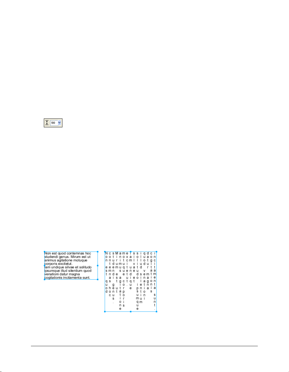
Zero represents normal kerning. Positive values move letters farther apart. Negative values
move letters closer together.
■ Hold down Control (Windows) or Command (Macintosh) while pressing the Left Arrow or
Right Arrow keys on the keyboard.
The Left Arrow key increases the space between letters by 1%, and the Right Arrow key
moves letters closer together by 1%.
Tip: Hold down Shift and Control (Windows) or Shift and Command (Macintosh) while pressing
the Left Arrow or Right Arrow keys to adjust kerning by 10% increments.
Setting leading
Leading determines the distance between adjacent lines in a paragraph. Leading can be measured
in pixels or as a percentage of the distance, in points, separating the lines baseline to baseline.
You can use the Property inspector or the keyboard to set leading.
Leading options in the Property inspector
To set the leading of selected text in the Property inspector:
1 In the Property inspector, drag the Leading pop-up slider or enter a value in the text box. The
default is 100%.
2 To change the leading unit type, choose % or px (pixels) from the Leading Units pop-up menu.
To set the leading of selected text using the keyboard:
• Hold down Control (Windows) or Command (Macintosh) while pressing the Up Arrow or
Down Arrow keys.
The Up Arrow key increases the space between lines, and the Down Arrow key moves lines
closer together.
Tip: Hold down Shift and Control (Windows) or Shift and Command (Macintosh) while pressing
the Up Arrow or Down Arrow keys to adjust leading by increments of 10.
Setting text orientation
A text block can be oriented horizontally or vertically. By default, text is oriented horizontally.
Horizontal and vertical orientation
Editing text 85
Page 86
Text can also flow right to left or left to right.
Text flowing right to left and left to right
In Fireworks, you set horizontal and vertical orientation as well as the direction of text flow in the
Property inspector. These settings apply to entire text blocks only.
To set the orientation of a selected text block:
1 Click the Text Orientation button in the Property inspector.
2 Select an orientation option from the pop-up menu:
Horizontal Left to Right is the default setting for text in Fireworks for most languages. It
orients text horizontally and displays characters from left to right.
Horizontal Right to Left orients text horizontally and displays characters from right to left.
It is useful for displaying text in languages where text flows from right to left, such as Hebrew
or Arabic.
Vertical Left to Right orients text vertically. If you apply this to lines of text separated by hard
or soft returns, each line of text is displayed as a column. The columns flow from left to right.
Vertical Right to Left orients text vertically. Multiple lines of text separated by returns are
displayed as columns that flow from right to left. This option is useful for displaying text in
languages such as Japanese in which text flows from right to left in columns.
Note: Vertical text characters always flow from top to bottom. Choosing one of the Vertical
orientation options affects only the order of text columns, not the order of text characters.
Setting text alignment
Alignment determines the position of a paragraph of text relative to the edges of its text block. In
horizontal alignment, text is aligned relative to the left and right edges of a text block. In vertical
alignment, text is aligned relative to the top and bottom edges of a text block. For more
information on setting horizontal or vertical text orientation, see “Setting text orientation”
on page 85.
You can align horizontal text to the left or right edges of the text block, center it, or fully justify it,
so that text aligns to both the left and right edges. By default, horizontal text is left-aligned.
Vertical text can be aligned to the top or bottom of a text block, centered within the text block, or
fully justified between both the top and bottom edges.
To achieve a stretched effect, or to fit text into a specific space, you can set the alignment
to stretch the text horizontally (for horizontally oriented text) or vertically (for vertically
oriented text).
Horizontal text stretched to fill a text block
86 Chapter 4: Using Text
Page 87

The alignment controls appear in the Property inspector when text is highlighted or a text block
is selected.
Text alignment options in the Property inspector
To set text alignment:
1 Select the text.
2 Click an alignment button in the Property inspector.
Indenting text
You can indent the first line of a paragraph using the Property inspector. Indention is measured
in pixels.
Paragraph indent option in the Property inspector
If the Property inspector is minimized, click the expander arrow in the lower right corner to see
all properties.
To indent the first line of selected paragraphs:
• In the Property inspector, drag the Paragraph Indent pop-up slider or enter a value in the
text box.
Setting paragraph spacing
You can specify the amount of spacing you want before and after paragraphs using the Property
inspector. Paragraph spacing is measured in pixels.
Paragraph spacing options in the Property inspector
If the Property inspector is minimized, click the expander arrow in the lower right corner to see
all properties.
To set the space that precedes selected paragraphs:
• In the Property inspector, drag the Space Preceding Paragraph pop-up slider or enter a value in
the text box.
To set the space after selected paragraphs:
• In the Property inspector, drag the Space After Paragraph pop-up slider or enter a value in the
text box.
Editing text 87
Page 88

Smoothing text edges
To smooth out a text edge, you anti-alias it. This makes the edges of the text blend into the
background so that the text is cleaner and more readable when it is large.
Original text; after smoothing
You use the Property inspector to set anti-aliasing. If the Property inspector is minimized, click
the expander arrow in the lower right corner to see all properties. Anti-aliasing applies to all
characters in a given text block.
No Anti-Alias disables text smoothing.
Crisp Anti-Alias creates a sharp transition between the edges of the text and the background.
Strong Anti-Alias creates a very abrupt transition between the edges of the text and the
background, preserving the shapes of the text characters and enhancing detailed areas of
the characters.
Smooth Anti-Alias creates a soft transition between the edges of the text and the background.
System Anti-Alias uses the text smoothing method provided by Windows XP or Mac OS X.
Custom Anti-Alias provides the following expert-level controls over anti-aliasing:
Oversampling determines the amount of detail used for creating the transition between the
text edges and the background.
Sharpness determines the smoothness of the transition between the text edges and
the background.
Strength determines how much the text edges blend into the background.
To apply an anti-aliased edge to selected text:
• In the Property inspector, choose one of options from the Anti-Aliasing pop-up menu:
Note: When you open vector files, such as FreeHand files, in Fireworks, text is anti-aliased. You can
edit this attribute using the Property inspector.
Expanding and contracting character width
You can expand or contract the character width of horizontal text using the Horizontal Scale
option in the Property inspector.
Horizontal scale is measured in percentage values. 100% is the default.
Horizontal Scale option in the Property inspector
If the Property inspector is minimized, click the expander arrow in the lower right corner to see
all properties.
88 Chapter 4: Using Text
For more information, see Fireworks Help.
Page 89
To expand or contract selected characters:
• In the Property inspector, drag the Horizontal Scale pop-up slider or enter a value in the text
box. Drag the slider higher than 100% to expand the width or height of the characters, and
drag it lower to reduce their width or height.
Setting baseline shift
Baseline shift determines how closely text sits above or below its natural baseline. If there is no
baseline shift, the text sits on the baseline. You can use baseline shift to create subscript and
superscript characters.
The baseline shift controls are in the Property inspector. Baseline shift is measured in pixels.
Baseline Shift option in the Property inspector
To set baseline shift for selected text:
• In the Property inspector, drag the Baseline Shift pop-up slider or enter a value in the text box
to specify how low or high, respectively, Fireworks should place the subscript or superscript
text. Enter positive values to create superscript characters. Enter negative values to create
subscript characters.
Applying strokes, fills, and effects to text
You can apply strokes, fills, and effects to text in a selected text block as you would to any other
object. You can apply any style in the Styles panel to text, even if it is not a text style. You can also
create a new style by saving text attributes.
After you create text, it remains editable in Fireworks. Strokes, fills, effects, and styles are updated
automatically as you edit the text.
Text with stroke, fill, effect, and style applied
You can apply solid text color to highlighted text in a text block. However, stroke attributes, Live
Effects, and nonsolid fill attributes such as gradient fills are applied to all text in a selected text
block, not just to the highlighted text.
For more information about strokes and fills, see Chapter 5, “Applying Color, Strokes, and Fills,”
on page 97. For more information about using styles, see “Using styles” on page 155. For
information about Live Effects, see “Applying Live Effects” on page 120.
The Text tool does not retain stroke or Live Effect settings when you create a new text block.
However, you can save stroke, fill, and Live Effects attributes that you apply to text for reuse as a
style in the Styles panel. Saving text attributes as a style saves only the attributes, not the text itself.
Applying strokes, fills, and effects to text 89
Page 90

To save text attributes as a style:
1 Create a text object and apply the attributes you want.
2 Select the text object.
3 Choose New Style from the Styles panel Options menu.
4 Choose the properties for the new style and name it.
5 Click OK.
Attaching text to a path
To free text from the restrictions of rectangular text blocks, you can draw a path and attach text to
it. The text flows along the shape of the path and remains editable.
A path to which you attach text temporarily loses its stroke, fill, and effect attributes. Any stroke,
fill, and effect attributes you apply subsequently are applied to the text, not the path. If you then
detach the text from the path, the path regains its stroke, fill, and effect attributes.
Note: Attaching text that contains hard or soft returns to a path can produce unexpected results.
If text attached to an open path exceeds the length of the path, the remaining text returns and
repeats the shape of the path.
Text on a path that returns and repeats the path shape
To place text on a path:
1 Shift-select a text block and a path.
2 Choose Text > Attach to Path.
To detach text from a selected path:
• Choose Text > Detach from Path.
Editing paths and text attached to paths
Text that you have attached to a path remains editable. In addition, you can edit the shape of
the path.
To edit text attached to a path, do one of the following:
• Double-click the text-on-a-path object with the Pointer or the Subselection tool.
• Choose the Text tool and select the text to edit.
90 Chapter 4: Using Text
Page 91
To edit the shape of the path:
1 Choose Text > Detach from Path.
2 Edit the path.
3 Place the text back on the path.
Changing text orientation and direction on a path
The order in which you draw a path establishes the direction of the text attached to it.
For example, if you draw a path from right to left, the attached text appears backward and
upside down.
Text attached to a path drawn right to left
You can change the orientation or reverse the direction of the text attached to a path. You can also
change the starting point of text on a path.
To change the orientation of text on a selected path:
• Choose Text > Orientation and select an orientation.
Text rotated around a path
Text oriented vertically on a path
Text skewed vertically around a path
Text skewed horizontally around a path
To reverse the direction of text on a selected path:
• Choose Text > Reverse Direction.
Attaching text to a path 91
Page 92

To move the starting point of text attached to a path:
1 Select the text-on-a-path object.
2 In the Property inspector, enter a value in the Text Offset text box. Then press Enter.
Note: If the Property inspector is minimized, click the expander arrow in the lower right corner to
see all properties.
Transforming text
You can transform text blocks in the same ways you can transform other objects. You can scale,
rotate, skew, and flip text to create unique text effects.
You can still edit the transformed text, although severe transformations may make the text
difficult to read. When a text block transformation causes text to be resized or scaled, the resulting
font size appears in the Property inspector when the text is selected.
Converting text to paths
You can convert text to paths and then edit the shapes of the letters as you would any vector
object. All vector-editing tools are available after you convert text to paths. However, you can no
longer edit it as text.
To convert selected text to paths:
• Choose Text > Convert to Paths.
Text converted to paths retains all of its visual attributes, but you can edit it only as paths. You
can edit the converted text as a group or edit the converted characters individually.
To edit converted text character paths individually, do one of the following:
• Select the converted text with the Subselection tool.
• Select the converted text and choose Modify > Ungroup.
You can edit the individual converted character paths using the vector-editing tools. For more
information on editing paths, see “Editing paths” on page 71.
You can create a composite path from a text object that was created by converting text to paths.
To create a composite path from a path group that was created by converting text to paths:
1 Select the path group.
2 Choose Modify > Ungroup.
3 Choose Modify > Combine Paths > Join.
92 Chapter 4: Using Text
Page 93

Importing text
You can copy text from a source document and paste into the current Fireworks document, or
you can drag it from the source to the current document. You can also open or import an entire
text file in Fireworks.
Fireworks can import RTF (rich text format) and ASCII (plain text) formats.
To open or import a text file:
1 Choose File > Open or File > Import.
2 Navigate to the folder containing the file.
3 Choose the file and click OK.
Photoshop text
You can open or import a Photoshop file containing text. You can also copy text from a
Photoshop file and paste into the current Fireworks document or drag it from the Photoshop file
to the current document.For more information, see Fireworks Help.
RTF files
When importing RTF text, Fireworks maintains these attributes:
• Font, size, and style (bold, italic, underline)
• Alignment (left, right, center, justified)
• Leading
• Baseline shift
• Range kerning
• Horizontal scale
• Color of the first character
All other RTF information is ignored.
In Fireworks, you cannot import RTF text by copying and pasting or dragging and dropping.
ASCII text
You can import ASCII text using any of the import methods. Imported ASCII text is set to the
current default font, 12 pixels high, and to the current fill color.
Handling missing fonts
If you open a document in Fireworks that contains fonts not installed on your computer,
Fireworks asks if you want to replace the fonts or maintain their appearance. This is useful if you
share files with users on other computers that may not have the same fonts installed.
Choosing Maintain Appearance replaces the text with a bitmap image that represents the
appearance of the text in its original font. You can still edit the text, but when you do so,
Fireworks replaces the bitmap image with a font that’s installed on your system. This can cause
the appearance of the text to change.
Importing text 93
Page 94

You can choose fonts to replace the missing fonts. After you replace fonts, the document opens
and you can edit and save the text. When the document is reopened on a computer that contains
the original fonts, Fireworks remembers and uses the original fonts.
To select a replacement font:
1 Open a document with missing fonts.
The Missing Fonts dialog box opens.
2 Choose a missing font from the Change Missing Font list.
3 Do one of the following:
■ Choose a replacement font from the To list.
■ Choose to display the text in the default system font.
■ To leave the missing font as is, click No Change.
4 Click OK.
The next time you open a document with the same missing fonts, the Missing Fonts dialog box
includes the font you chose.
Checking spelling
You can use the Check Spelling command in the Text menu to check spelling for specific text
blocks or all text in a document.
To spell-check text:
1 Select one or more text blocks. If no text blocks are selected, Fireworks checks spelling in the
entire document.
2 Choose Text > Check Spelling.
3 If you have not checked spelling before in Fireworks, you see a dialog box asking you to choose
a dictionary. Click OK to close the dialog box. Choose a language from the Dictionary list, and
click OK.
If you don’t choose a language, Fireworks prompts you to choose a language dictionary every
time you spell-check a document.
Note: The Macromedia.tlx option is always selected at the top of the Dictionary list. For more
information about this option, see “Customizing spell checking” on page 95.
4 The Check Spelling dialog box opens. For each word found, choose the appropriate option:
Add to Personal adds the unrecognized word to your personal dictionary.
Ignore skips the current instance of the unrecognized word.
Ignore All skips all instances of the unrecognized word during the current spell-check session.
The next time you spell-check, Fireworks once again identifies the word as unrecognized.
Change replaces the current instance of the unrecognized word with text that you type in the
Change To box or with the selection in the Suggestions list.
Change All replaces all instances of the unrecognized word in the same manner.
Delete removes a duplicate word when one is found.
When it finishes checking the spelling in a document, Fireworks closes the Check Spelling
dialog box and displays a message indicating that the spell-check is complete.
94 Chapter 4: Using Text
Page 95

Customizing spell checking
You can customize the way Fireworks spell-checks documents using the Spelling Setup dialog box.
From here you can specify one or more language dictionaries for Fireworks to use during spell
checking, as well as edit the words in your personal dictionary. You can also specify which items
you want Fireworks to spell-check, including Internet and file addresses.
To customize spell checking in Fireworks:
1 Do one of the following:
■ Choose Text > Spelling Setup.
■ Click the Setup button in the Check Spelling dialog box.
2 Choose the desired options in the Spelling Setup dialog box:
■ Choose one or more language dictionaries.
Note: The Macromedia.tlx option is always selected at the top of the dictionary list. This is the file
that contains your custom spelling dictionary.
■ Browse for a custom dictionary by clicking the folder icon beside the Personal Dictionary
Path text box.
■ Edit the custom dictionary by clicking the Edit Personal Dictionary button and adding,
deleting, or modifying words in the list.
■ Choose the types of words you want to include in the spell-check.
3 Click OK.
Using the Text Editor
In Fireworks 4 and previous versions, the Text Editor was used to create and edit text. All textediting and formatting options found in the Text Editor are now located in the Property
inspector. However, you still have access to the Text Editor through the Text menu.
The Text Editor is useful for working with text that might be difficult to edit onscreen, such as
large text blocks, text attached to a path, or text with hard-to-read fonts and sizes. You can choose
to display such text in the system font and default size if necessary to make editing easier.
To display the Text Editor:
1 Select a text block and choose Text > Editor.
2 Modify and format the text using the options available.
3 Click OK to apply changes and close the Text Editor.
To view text in the system font:
• Deselect Show Font in the Text Editor.
To view text in the default size:
• Deselect Show Size & Color in the Text Editor.
Using the Text Editor 95
Page 96

96 Chapter 4: Using Text
Page 97

CHAPTER 5
Applying Color, Strokes, and Fills
Macromedia Fireworks MX 2004 has a wide range of panels, tools, and options for organizing
and choosing colors, and applying colors to bitmap images and vector objects.
In the Swatches panel, you can choose a preset swatch group such as Color Cubes, Continuous
Tone, or Grayscale, or you can create custom swatch groups that include your favorite colors or
colors approved by your client. In the Color Mixer, you can choose a color model such as
Hexadecimal, RGB, or Grayscale, and then choose stroke and fill colors directly from the color
bar or by entering specific color values.
Throughout the Fireworks workspace you will find color boxes that show the current color
choices for options and object characteristics. When you click a color box, you see a color pop-up
window from which you can choose a color for the color box. Move the pointer away from an
open color pop-up window, and you can click any color on your screen to apply it to the
color box.
The Colors section of the Tools panel contains stroke and fill color controls and other color
options. The Bitmap section contains the Paint Bucket, Gradient Fill, and Eyedropper tools,
which you can use to apply color to bitmap selections, areas of similar color, and vector objects.
For information on these bitmap tools, see Chapter 2, “Working with Bitmaps,” on page 29.
Note: For information about color correction using Live Effects and filters, see “Adjusting bitmap
color and tone” on page 39.
97
Page 98
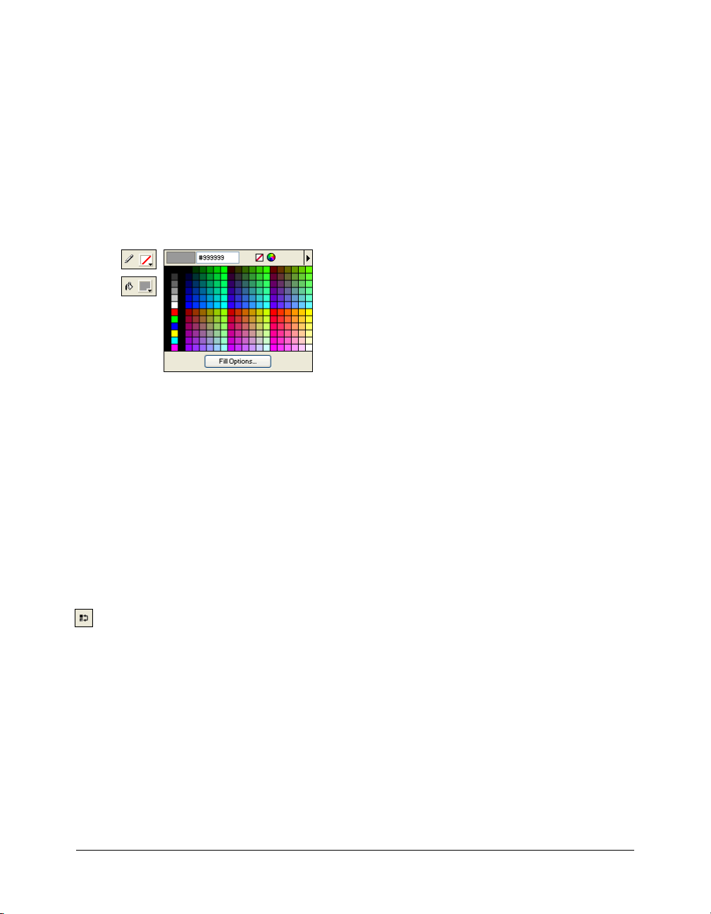
Using the Colors section of the Tools panel
The Colors section of the Tools panel contains controls for activating the Stroke Color and Fill
Color boxes, which in turn determine whether the strokes or fills of selected objects are affected
by color choices. Also, the Colors section has controls for quickly resetting colors to the default,
setting the stroke and fill color settings to None, and swapping fill and stroke colors.
To make the Stroke Color or Fill Color box active:
• Click the icon next to the Stroke Color or Fill Color box in the Tools panel. The active color
box area appears as a depressed button in the Tools panel.
Note: The Paint Bucket tool fills pixel selections and vector objects with the color shown in the Fill
Color box in the Tools panel.
Color boxes in the Tools panel and the color pop-up window
To reset colors to the default:
• Click the Default Colors button in the Tools panel or in the Color Mixer.
To remove the stroke and fill from selected objects using the No Stroke or Fill button:
1 Click the No Stroke or Fill button in the Colors section of the Tools panel.
The active characteristic changes to a stroke or fill of None.
2 To set the inactive characteristic to None as well, click the No Stroke or Fill button again.
Note: You can also set the fill or stroke of selected objects to None by clicking the Transparent
button in any Fill Color or Stroke Color box pop-up window, or by choosing None from the Fill
Options or Stroke Options pop-up menu in the Property inspector.
To swap fill and stroke colors:
• Click the Swap Colors button in the Tools panel or in the Color Mixer.
Organizing swatch groups and color models
The Swatches panel and Color Mixer combine to form the Colors panel group. In the Swatches
panel you can view, change, create, and edit swatch groups, as well as choose stroke and fill colors.
You can use the Color Mixer to choose a color model, mix stroke and fill colors by dragging color
value sliders or entering color values, and choose stroke and fill colors directly from the color bar.
98 Chapter 5: Applying Color, Strokes, and Fills
Page 99

Applying colors using the Swatches panel
The Swatches panel displays all the colors in the current swatch group. You can use the Swatches
panel to apply stroke and fill colors to selected vector objects or text.
To apply a color to the stroke or fill of a selected object using the Swatches panel:
1 Click the icon next to the Stroke Color or Fill Color box in the Tools panel or Property
inspector to make it active.
2 If the Swatches panel is not already open, choose Window > Swatches.
3 Click a swatch to apply the color to the stroke or fill of the selected object. The color appears in
the active Stroke Color or Fill Color box.
Changing swatch groups
You can easily switch to another swatch group or create your own. The Swatches panel Options
menu contains the following swatch groups: Color Cubes, Continuous Tone, Macintosh System,
Windows System, and Grayscale. You can import custom swatches from color palette files saved
as ACT or GIF files.
To choose a swatch group:
• Choose a swatch group from the Swatches panel Options menu.
Note: Choosing Color Cubes returns you to the default swatch group.
To choose a custom swatch group:
1 Choose Replace Swatches from the Swatches panel Options menu.
2 Navigate to the folder and choose a swatch file.
3 Click Open.
The color swatches in the swatch file replace the previous swatches.
Note: For information on creating a custom swatch group, see “Customizing the Swatches panel”
on page 100 and “Saving palettes” on page 240.
To add swatches from an external color palette to the current swatches:
1 Choose Add Swatches from the Swatches panel Options menu.
2 Navigate to the desired folder and choose a color palette file.
Note: Fireworks can add new swatches from palettes exported as ACT or GIF files.
3 Click OK.
Fireworks adds the new swatches at the end of the current swatches.
Organizing swatch groups and color models 99
Page 100
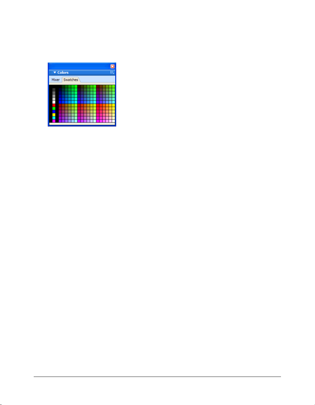
Customizing the Swatches panel
You can add, delete, replace, and sort color swatches or entire swatch groups using the Swatches
panel.
Note: Choosing Edit > Undo does not undo swatch additions or deletions.
Swatches panel
To add a color to the Swatches panel:
1 Choose the Eyedropper tool from the Tools panel.
2 Choose the number of pixels to sample from the Sample pop-up menu in the Property
inspector: 1 pixel, 3x3 Average, or 5x5 Average.
3 Click anywhere inside any open Fireworks Document window to sample a color.
4 Move the tip of the eyedropper pointer to the open space after the last swatch in the
Swatches panel.
The eyedropper pointer becomes the paint bucket pointer.
5 Click to add the swatch.
Tip: When you choose Snap to Web Safe in the Options menu of the color pop-up window, any
non-websafe color you pick up with the eyedropper pointer is changed to the nearest websafe
color.
To replace a swatch with another color:
1 Choose the Eyedropper tool from the Tools panel.
2 Choose the number of pixels to sample from the Sample pop-up menu in the Property
inspector: 1 pixel, 3x3 Average, or 5x5 Average.
3 Click anywhere inside any Fireworks Document window to sample a color.
4 Hold down Shift and place the pointer over a swatch in the Swatches panel.
The pointer becomes the paint bucket pointer.
5 Click the swatch to replace it with the new color.
To delete a swatch from the Swatches panel:
1 Hold down Control (Windows) or Command (Macintosh) and place the pointer over a swatch.
The pointer becomes the scissors pointer.
2 Click the swatch to delete it from the Swatches panel.
100 Chapter 5: Applying Color, Strokes, and Fills
 Loading...